

Dometic SeaLand VHT12 Owner's Manual
®
SeaLand
VACUUM HOLDING TOILET
OWNER’S MANUAL
VHT12
WARNING
!
This manual must be read and understood before installation, adjustment,
service, or maintenance is performed.
Modication of this product can
result in property damage.
Dometic Sanitation Corporation
13128 State Rt 226, PO Box 38
Big Prairie, OH 44611
SeaLand Product Customer Service: 1-800-321-9886
www.DometicUSA.com
1

TABLE OF CONTENTS
Product Features . . . . . . . . . . . . . . . . . . . . . . . . . . . . 2
Major Components . . . . . . . . . . . . . . . . . . . . . . . . . . . 2
Principles of Operation . . . . . . . . . . . . . . . . . . . . . . . . 3
System Layout . . . . . . . . . . . . . . . . . . . . . . . . . . . . . . 3
Component Locating Procedure. . . . . . . . . . . . . . . . . 4
Key Installation Points . . . . . . . . . . . . . . . . . . . . . . . . 4
Installation of Components. . . . . . . . . . . . . . . . . . . . . 5
Winterizing . . . . . . . . . . . . . . . . . . . . . . . . . . . . . . . . . 6
Troubleshooting Guide . . . . . . . . . . . . . . . . . . . . . .6 - 7
Dimensional Specications. . . . . . . . . . . . . . . . . . . . . 7
Manufacturer’s One-Year Limited Warranty . . . . . . . . 8
PRODUCT FEATURES
The Vac u um H ol d in g Tan k ( V HT ) br i ng s th e
technology, comfort and efficie ncy of Dometic’s
renowned VacuFlush® vacuum sanitation systems to
smaller boats in an easy-to-use, and easy-to-maintain
package.
Simple Installation
• All system components are “installation ready.”
• No solvent bonding is required.
• Removable hose insert ttings make hose installation
simple.
• Vacuum pump and switch are pre-wired at factory.
• Easy to mount.
Reliability is Built-In
• No impellers or macerators. Motor can run without
burning up.
MAJOR COMPONENTS
The Vacuum Holding Tank (VHT) system consists of a
VacuFlush toilet or EcoVac™ toilet and the Model VHT
Vacuum Holding Tank. The VHT is a unique combination of the vacuum tank, vacuum pump and holding tank
components used in a standard VacuFlush toilet
system.
Each toilet series consists of several models, allowing
for a multitude of installation variations: a rear discharge
standard height unit, a bottom discharge standard height
unit, and a bottom discharge low-prole unit designed
to t on a platform.
The vacuum toilet must be purchased separately;
it is not included with the VHT.
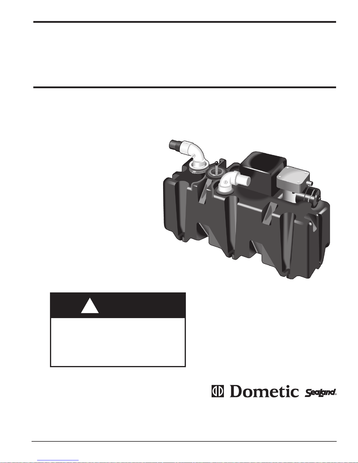
VACUUM HOLDING TANK (VHT)
The VHT produces and stores vacuum between ushes.
The vacuum holding tank is made of highly durable
polyethylene. The pump is integrally connected with
the vacuum tank. The vacuum pump is electric and draws
only 2 to 4 amps of current at 12 VDC.
One vacuum holding tank is required for each toilet.
Two or more toilets cannot be connected to one VHT.
The VHT contains the pre-set pressure differential switch
control that turns the pump on and off when the proper
level of vacuum is created.
A unique component on the VHT is the Vacuum Relief
Valve (VRV). The VRV prevents excessive vacuum from
accumulating in the tank. The VRV is calibrated to open
at 13” of vacuum and close at 11” of vacuum. This feature
is benecial during pump-outs.
The VHT system comes equipped with a full level oat
switch. This oat switch is wired directly to an automatic
shutdown relay. The relay prohibits the vacuum pump
from generating vacuum once the tank is full. A full level
indicator light should be wired to the full oat, by the
installer. If a full level indicator light was not installed,
order part number 318714 from Dometic. The indicator
light is not part of the basic system.
VACUUM HOSE
To complete a VacuFlush installation, OdorSafe® Plus
Sanitation Hose or rigid PVC pipe (Schedule 40 or
heavier) must be used. OdorSafe Plus hose is specially
formulated to provide up to 16 times greater resistance
to malodors than other “no-odor” marine hoses.
VACUUM TOILETS
The VacuFlush 500 Plus series features a large household-size bowl and seat. The VacuFlush 1000 series also
fea t ures a deep b o wl with an a d u lt-sized s eat.
The VacuFlush 140 series (EcoVac) offers spacesaving models with adult-sized seats. All come with an
attractive, easy-to-use ush pedal.
2
PRINCIPLES OF OPERATION
VacuFlush systems use a small amount of water (one
pint to one quart) and the vacuum that is generated by
the vacuum pump to ush. Each toilet must be connected to a pressurized water system. Fresh water is
recommended and will result in an odor-free bathroom.
If seawater is used, the water should be ltered.
No complicated user instructions are required. Lifting the
ush lever adds water to the bowl. Pressing the ush
lever (or pulling the ush lever on a 106 toilet) opens a
mechanical seal that allows the vacuum force to pull the
waste from the bowl as clean water rinses the bowl. The
vacuum moves the waste (at approximately 7 feet [2.1 m]
per second) through a one-inch opening in the toilet base.
Incoming air fragments the waste as it passes through
the base opening. This process eliminates the need for
macerators or mechanical motors in the toilet base.
Next, the waste is transferred into the Vacuum Holding
Tank (VHT). System vacuum is monitored by a vacuum
switch that is located on the outside of the VHT. When
the switch senses a drop in vacuum in the system, it
automatically signals the pump to energize and bring the
vacuum back to operating level. This process is normally
completed in about one minute.
In a properly operating system, the stored vacuum will
“leak” down between ushes, causing the vacuum pump
to run for a short period. The pump should not run more
than once every three (3) hours after the last ush.
An “On-Off” night switch can be installed to silence the
vacuum pump during sleeping hours. The VacuFlush
Status Panel, an optional accessory, features an integral
circuit breaker that provides a convenient night switch.
IMPORTANT: Before pumping out the VHT,
it is recommended that the power to the system
be turned off. Then, ush the toilet. This releases
the stored vacuum in the tank, thus, allowing the
dockside pump to empty the waste out more easily.
If the dockside pump has low suction capability,
you may need to flush the toilet a second time
during the pump out.
The Vacuum Relief Valve (VRV) will automatically open
at 13” of vacuum and is spring loaded to close at 11” of
vacuum to prevent leaking during normal operation.
SYSTEM LAYOUT
The Vacuum Holding Tank (VHT) system can be installed
on most boats that presently use a portable, manual or
electric toilet. The following procedure will be helpful:
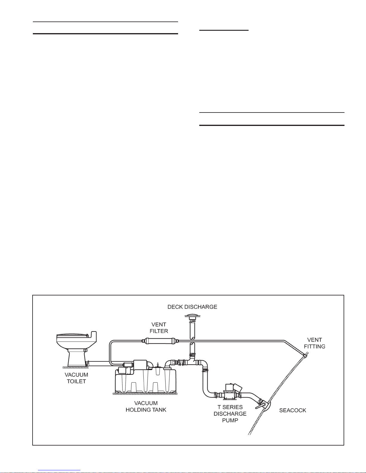
1. Review the typical system layout to get a general
idea of how the system will operate and what discharge
options will be considered (see Figure 1).
2. Draw or obtain a layout of the boat which allows
the location of head compartments, bulkheads, engine
space, tanks, through-hull ttings, etc. This layout should
include top views and side views and show relative distances and heights with reasonable accuracy.
3. Use the information in the Component Locating
Procedure section to help select the best locations for
your boat layout.
4. Routing of vacuum hose should be considered
when selecting a location for the toilet and the (VHT). A
maximum of 20 feet (6.1 m) of hose can be used between
the toilet and the VHT.
5. Before starting the actual installation, carefully review
the Key Installation Points.
Figure 1
3
 Loading...