

Page 1
EN
DE
FR
IT
NL
SANITATION
SANEO
Saneo® B, Saneo® C, Saneo® BLP, Saneo® CLP, Saneo® BS, Saneo® CS,
Cassette toilet
Installation Manual. . . . . . . . . . . . . . . . . . . . 19
Kassettentoilette
Montageanleitung. . . . . . . . . . . . . . . . . . . . 31
Toilettes à cassette
Instructions de montage . . . . . . . . . . . . . . .44
Toilette a cassetta
Indicazioni di montaggio . . . . . . . . . . . . . .57
Cassettetoilet
Montagehandleiding . . . . . . . . . . . . . . . . .70
Saneo
®
BW, Saneo® CW
Page 2

Page 3
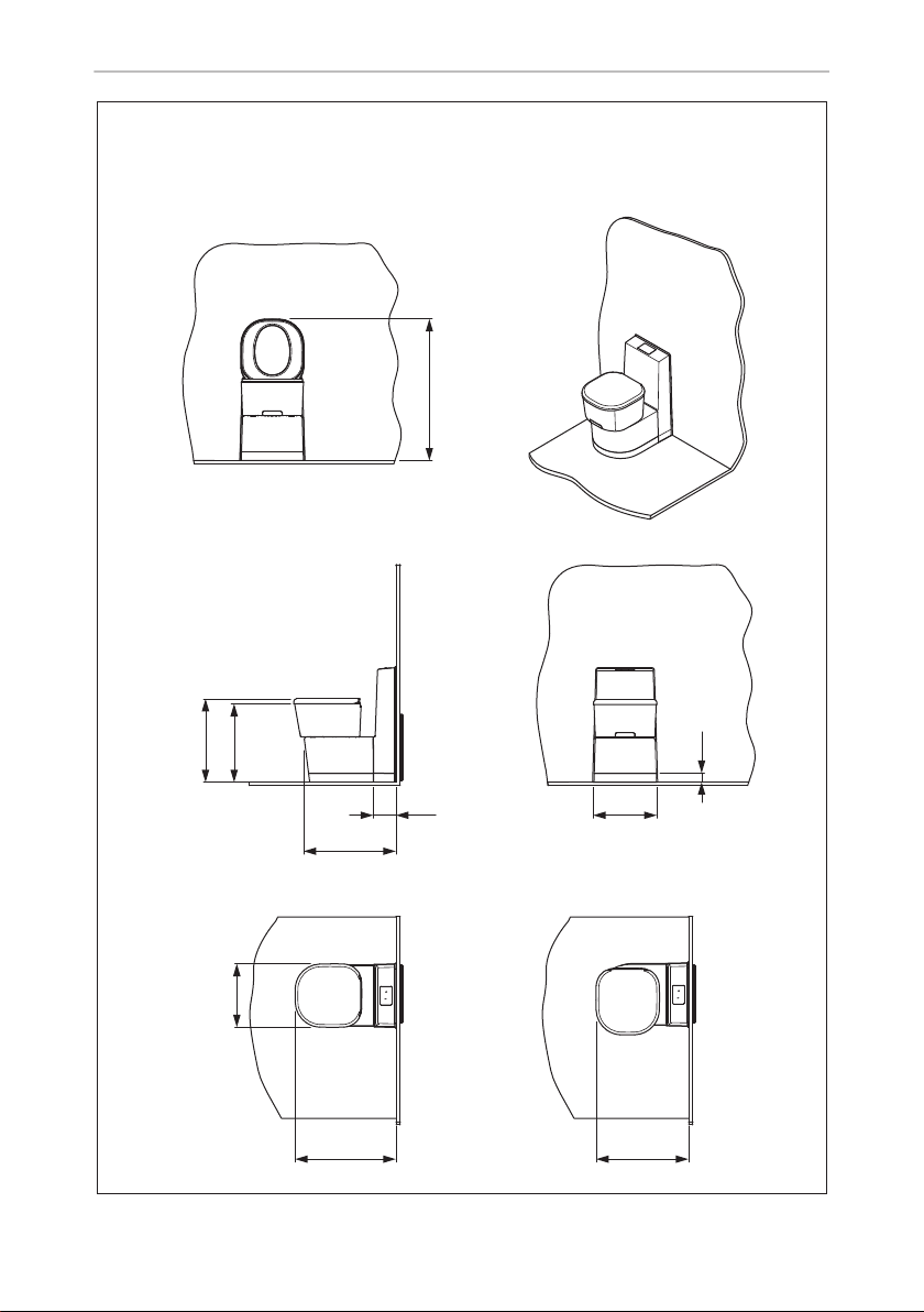
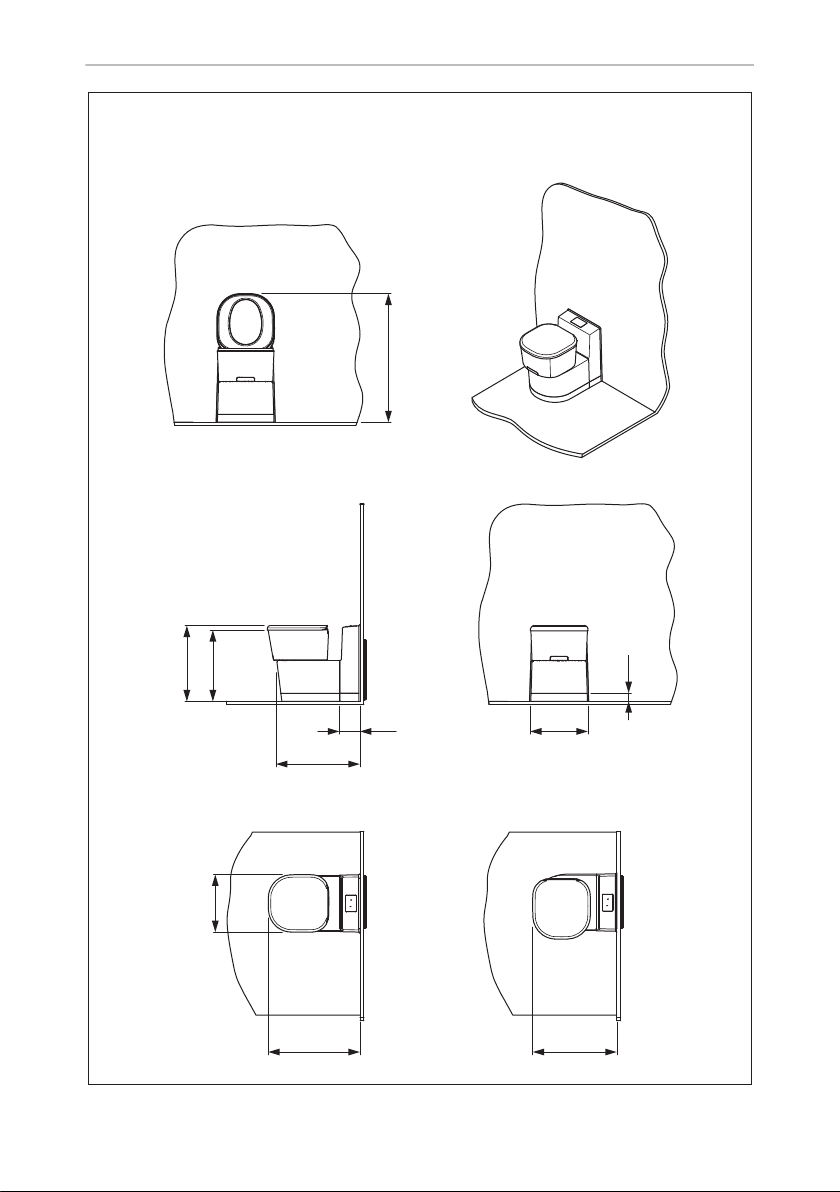
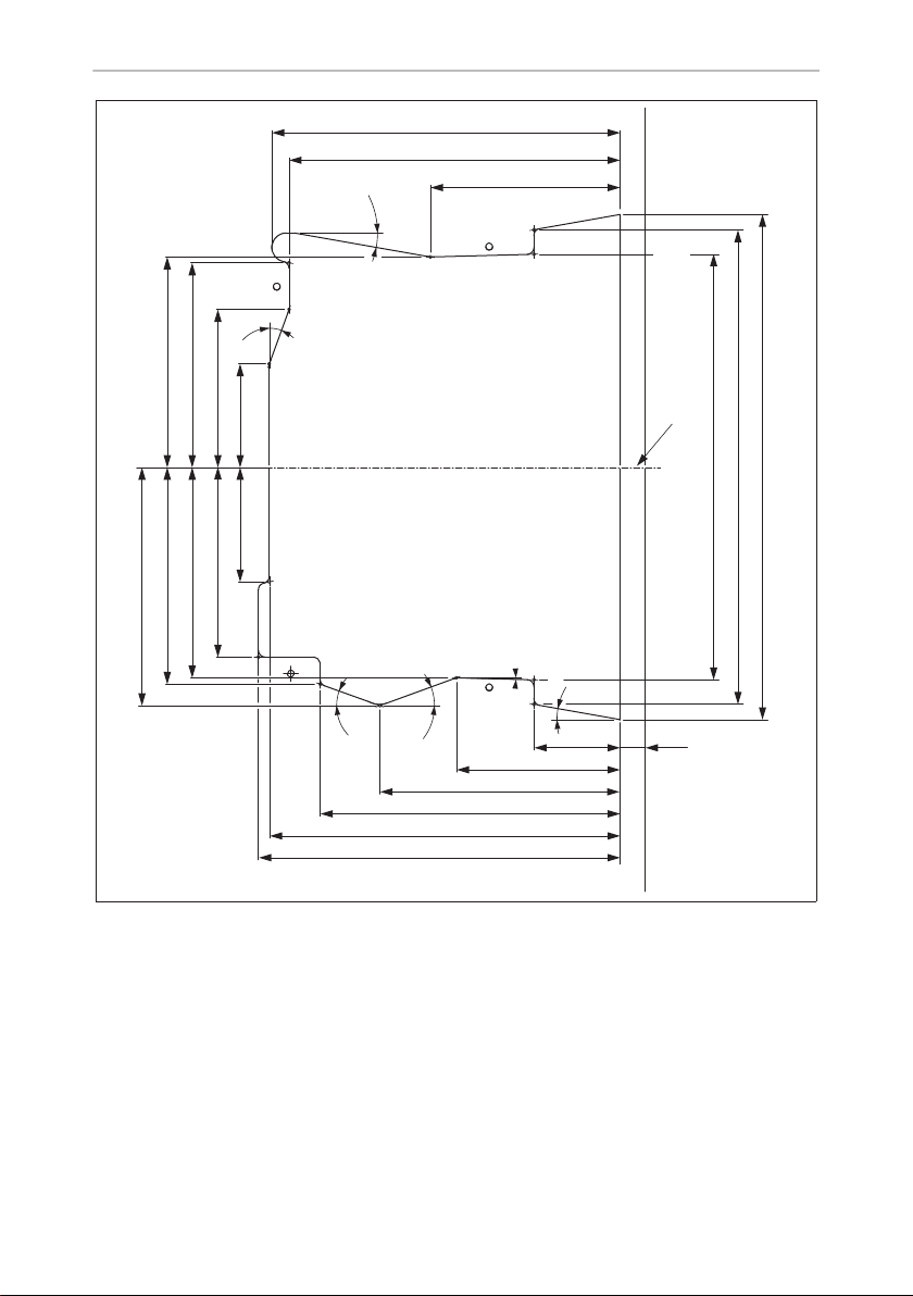
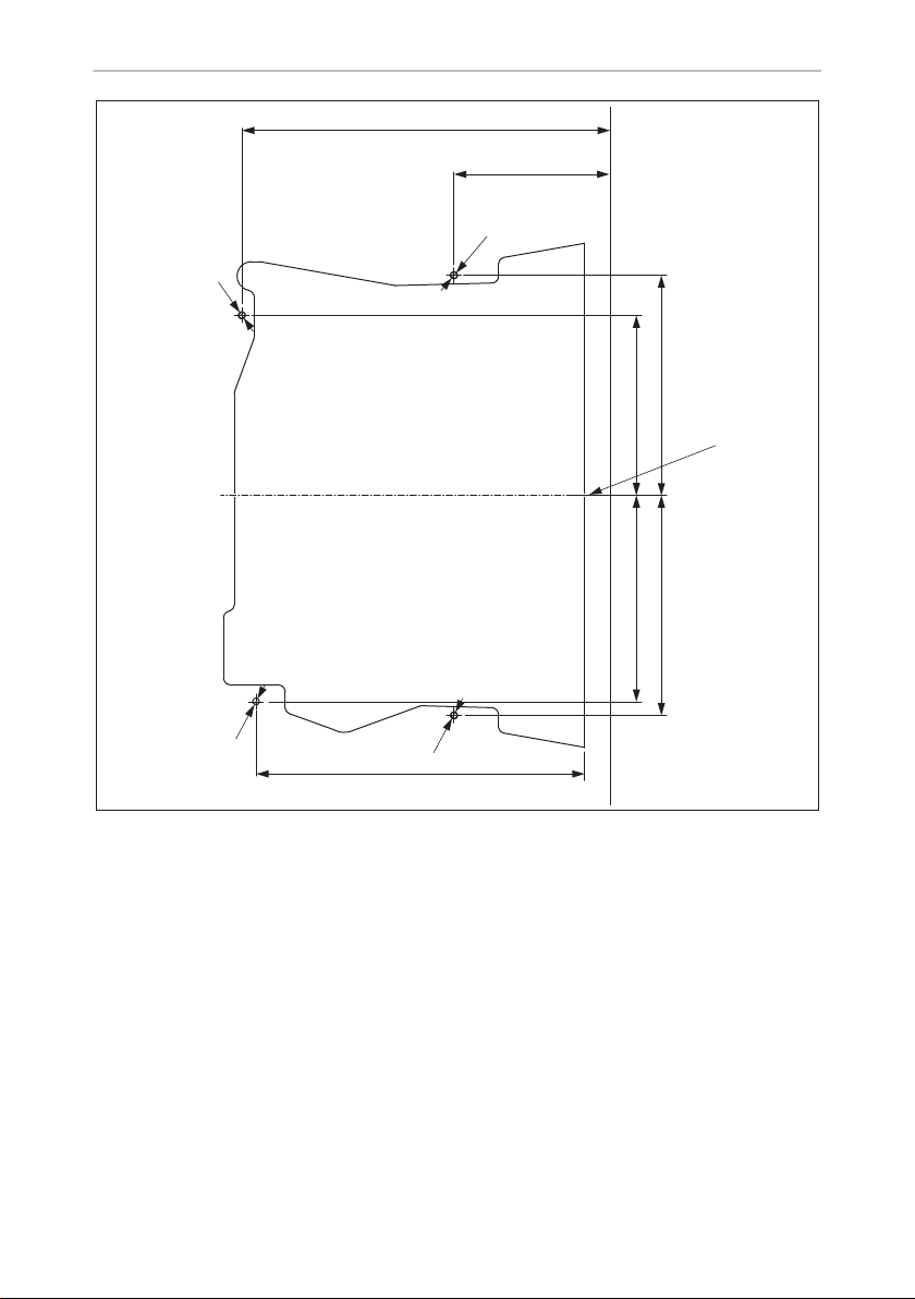
Saneo B, Saneo C
1
2
6 7 8
9
4
5
3
2
1
A
x
b
10
h
y
B
x
b
h
y
3
Page 4
1.
2. 3.
1.
2. 3.
3
Saneo B, Saneo C
4
Page 5
Saneo B, Saneo C
4
490
469
Saneo B, C
841
53
131 370
537
377
600 549
5
Page 6
Saneo B, Saneo C
5
490
469
Saneo BS, BW
Saneo CS, CW
841
53
131 372
538
377
600 549
6
Page 7
Saneo B, Saneo C
6
490
469
Saneo BLP, CLP
841
53
131 372
538
377
600 549
7
Page 8
Saneo B, Saneo C
7
253,6
241
138,1
10°
20°
152,9158
148,7
114,7
75,183,6
138,3
153,4
173,7
1,5°
10°
20°
20°
62,818,6
119,3
175
218,4
255,4
263,4
A
367,5
309,8
345,4
8
Page 9
Saneo B, Saneo C
8
Ø 5
Ø 5
268,6
113,9
Ø 5
131,3150,4
A
160,4 160,4
Ø 5
239,8
9
Page 10
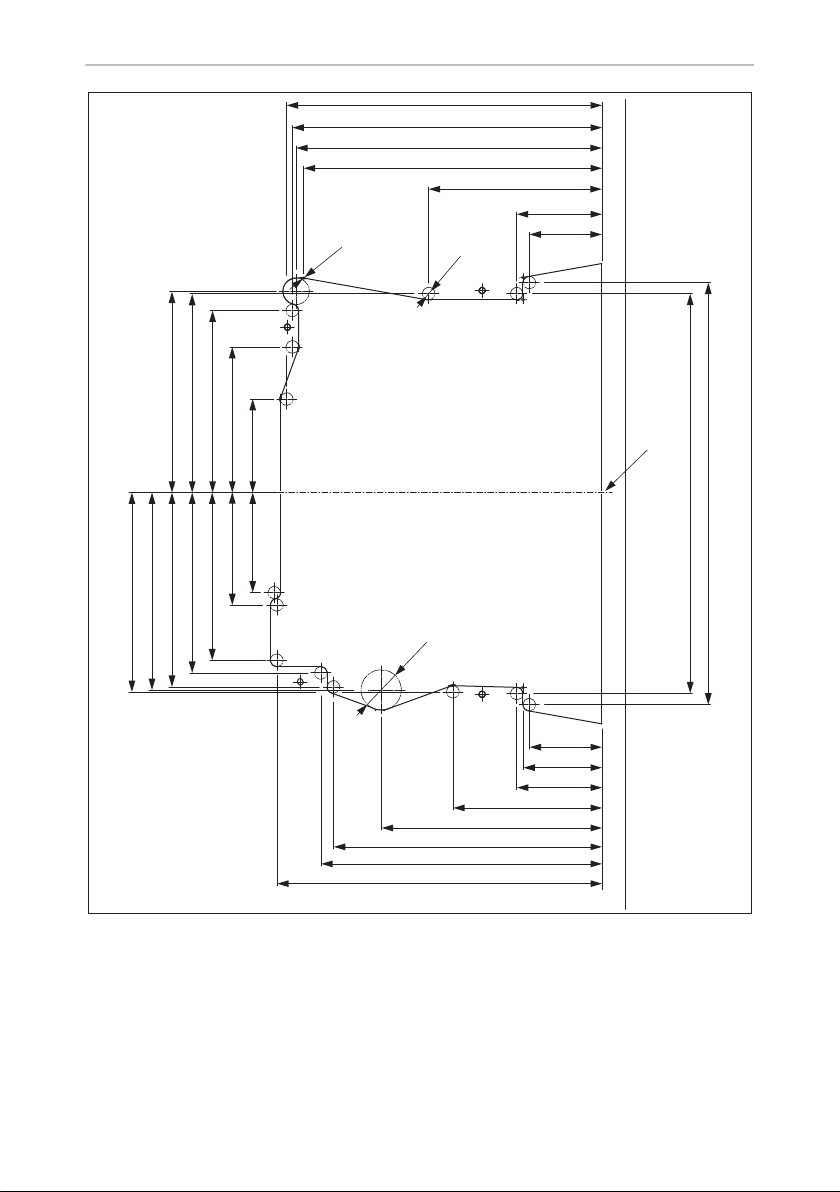
250,4
246
243,1
237
137,8
67,8
57,8
258,4
223,4
213,4
175,4
118,5
67,8
62,8
57,8
337
319,5
Ø 10
Ø 32
Ø 2
74,279,6
115,6
89,4
144,6
133,3
157,9
159,8
143,3
154,5
156,8
158,4
A
9
Saneo B, Saneo C
10
Page 11
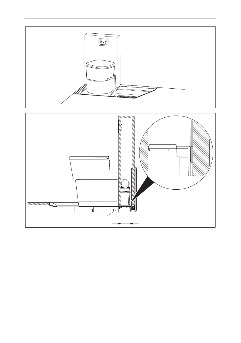
Saneo B, Saneo C
0
a
1
1
a
11
Page 12
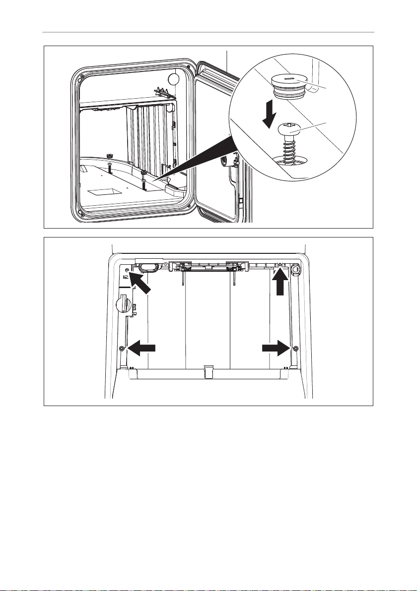
b
c
Saneo B, Saneo C
1
4x
2
12
Page 13

Saneo B, Saneo C
d
135
4
1:1
88
R = 10 mm
13
Page 14
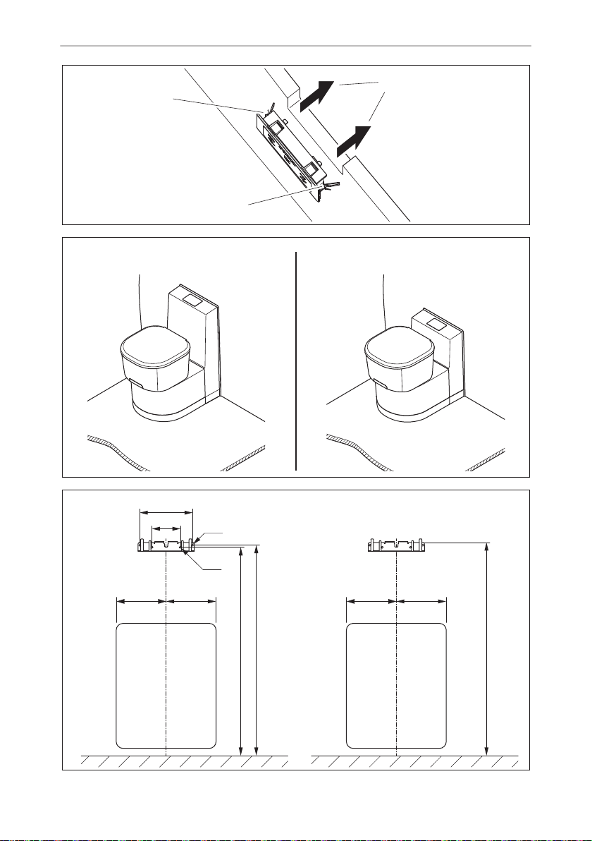
Saneo B, Saneo C
e
f
1
1
Saneo BW, Saneo CW
Saneo BS, Saneo CS
2
Saneo BLP, Saneo CLP
14
g
A
A
B
=
Ø5
Ø5
=
D
C
B
==
661
Page 15
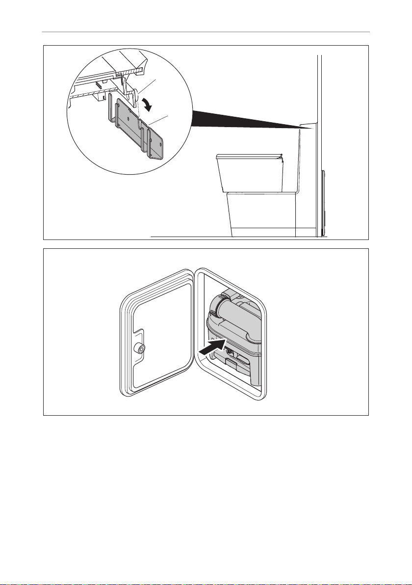
Saneo B, Saneo C
h
i
1
2
15
Page 16
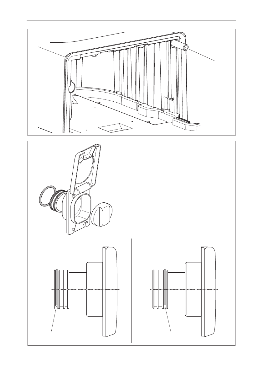
j
k
Saneo B, Saneo C
1
16
BA
1 1
Page 17
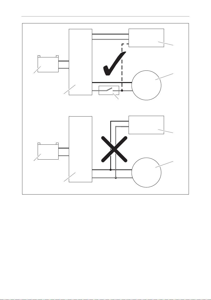
Saneo B, Saneo C
12 Vg
+
–
+
–
+
–
+
–
+
–
5
4
2
1
5
4
3
2
1
l
17
Page 18
1
456
1 32 2
4
6
5
A
B
m
n
A B C D
Saneo B, Saneo C
rt +
ws –
rt +
ws –
bl +
rt +
ws –
+ rt
– ws
+ bl
rt +
ws –
18
Page 19

EN
Saneo B, Saneo C
Please read this instruction manual carefully before installation and first
use, and store it in a safe place. If you pass on the product to another
person, hand over this instruction manual along with it.
Table of contents
1 Explanation of symbols . . . . . . . . . . . . . . . . . . . . . . . . . . . . . . . . . . . . . . 20
2 Safety instructions . . . . . . . . . . . . . . . . . . . . . . . . . . . . . . . . . . . . . . . . . . 20
2.1 General safety . . . . . . . . . . . . . . . . . . . . . . . . . . . . . . . . . . . . . . . . . . .21
2.2 Installation instructions . . . . . . . . . . . . . . . . . . . . . . . . . . . . . . . . . . . .21
3 Intended use. . . . . . . . . . . . . . . . . . . . . . . . . . . . . . . . . . . . . . . . . . . . . . . . .21
4 Technical description . . . . . . . . . . . . . . . . . . . . . . . . . . . . . . . . . . . . . . . . 22
4.1 Description of the components . . . . . . . . . . . . . . . . . . . . . . . . . . . . 22
5 Installing the toilet . . . . . . . . . . . . . . . . . . . . . . . . . . . . . . . . . . . . . . . . . . 23
5.1 Installing the service door . . . . . . . . . . . . . . . . . . . . . . . . . . . . . . . . . 23
5.2 Making wall cutouts . . . . . . . . . . . . . . . . . . . . . . . . . . . . . . . . . . . . . 23
5.3 Setting up the toilet . . . . . . . . . . . . . . . . . . . . . . . . . . . . . . . . . . . . . . 24
5.4 Setting up the Saneo B, Saneo C toilet . . . . . . . . . . . . . . . . . . . . . . 24
5.5 Setting up the Saneo BW, Saneo CW, Saneo BS, Saneo CS,
Saneo BLP, Saneo CLP toilets . . . . . . . . . . . . . . . . . . . . . . . . . . . . . . 26
5.6 Water connection . . . . . . . . . . . . . . . . . . . . . . . . . . . . . . . . . . . . . . . 26
5.7 Installation of the tank flap. . . . . . . . . . . . . . . . . . . . . . . . . . . . . . . . . 27
6 Electrical connection . . . . . . . . . . . . . . . . . . . . . . . . . . . . . . . . . . . . . . . . 28
7Technical data . . . . . . . . . . . . . . . . . . . . . . . . . . . . . . . . . . . . . . . . . . . . . . 30
19
Page 20

EN
Explanation of symbols Saneo B, Saneo C
1 Explanation of symbols
WARNING!
!
!
A
I
Safety instruction: Failure to observe this instruction can cause fatal or
serious injury.
CAUTION!
Safety instruction: Failure to observe this instruction can lead to injury.
NOTICE!
Failure to observe this instruction can cause material damage and impair
the function of the product.
NOTE
Supplementary information for operating the product.
2 Safety instructions
The manufacturer accepts no liability for damage in the following cases:
• Faulty assembly or connection
• Damage to the product resulting from mechanical influences and excess voltage
• Alterations to the product without express permission from the manufacturer
• Use for purposes other than those described in the operating manual
The declaration of conformity can be requested from the manufacturer (contact
information on the back).
20
Page 21

EN
Saneo B, Saneo C Intended use
2.1 General safety
WARNING!
!
A
• This device can be used by children aged 8 years or over, as well as by
persons with diminished physical, sensory or mental capacities or a
lack of experience and knowledge, providing they are supervised, or
have been taught how to use the device safely and are aware of the
resulting risks.
• Cleaning and user maintenance must not carried out by unsupervised
children.
• Children must be supervised to ensure that they do not play with the
device.
• The toilet may be installed only by trained personnel.
• All components of the system must be installed in frost-free areas. In
freezing temperatures, there is a risk of damage caused by frost.
• Do not use antifreeze. These agents may damage the cassette toilet.
• The operating pressure (water pressure) of the solenoid valve should
not exceed 6 bar. The solenoid valve is damaged by excessive pressure.
• The electrical installation must comply with national and local
regulations.
In Europe: EN 1645-1, EN 1646-1, EN 1648-1, EN 1648-2.
2.2 Installation instructions
The toilet must be installed so that it is easily accessible for service work, easy to
de-install and install, and easily removed from the vehicle.
3 Intended use
The toilet is designed for installation and use in recreational vehicles such as campervans or motor caravans.
21
Page 22

EN
Technical description Saneo B, Saneo C
4 Technical description
The cassette toilet Saneo consists of a toilet permanently installed in the vehicle and
a removable, mobile cassette as a holding tank. The cassette is externally accessible
through a door. Depending on the model, the toilet gets the rinse water from a tank
integrated in the housing or from a freshwater tank in the vehicle.
The following model versions of the toilet are available:
• Saneo B, Saneo C: freestanding, without water tank, without console
• Saneo BS, Saneo CS: freestanding, without water tank, with console
• Saneo BW, Saneo CW: freestanding, with a water tank in the console
• Saneo BLP, Saneo CLP: freestanding, without water tank, low console
Saneo C models can be equipped with an interval flush (optional). The water is
pumped into the toilet bowl in short spurts in order to achieve improved flush
wetting and cleaning. The wetting and cleaning depend on the amount of water
available in the vehicle.
4.1 Description of the components
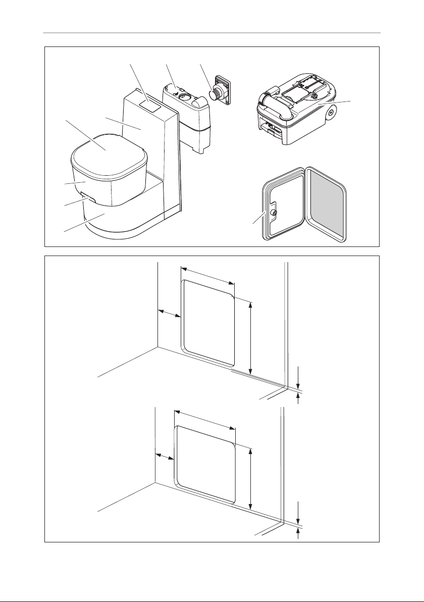
No. in
fig. 1, page 3
1 Housing for cassette tank
2 Draining slider for toilet bowl
3 Rotatable toilet bowl, plastic or ceramic
4 Lid and seat, removable
5Console
6 Control panel with level indicator and flushing
7
8
9 Cassette tank
10 Service door
22
Label
Only Saneo BW, CW
Only Saneo BW, CW: Tank flap (closable tank flap optional)
: Integrated freshwater tank
Page 23

EN
Saneo B, Saneo C Installing the toilet
5 Installing the toilet
5.1 Installing the service door
You can find the description for installing the service door in the enclosed document
(
Dometic Seitz SK 5, optional and model-dependent).
5.2 Making wall cutouts
Service door wall cutout
➤ Make a rectangular opening in the outer wall with the following dimensions
(fig. 2, page 3):
• A: For service door SK5 vertical:
–y
– w = 310 mm ± 1 mm
– h = 360 mm ± 1 mm
• B: for service door SK5 horizontal:
–y
– w = 360 mm ± 1 mm
– h = 310 mm ± 1 mm
= 12.5 mm, y
min
= 12.5 mm, y
min
max
max
= 22 mm
= 26 mm
The dimension x results from the placement of the toilet. Please note the position of
the service door (template (3) and (4) on the packaging).
Wall cutout for the tank flap
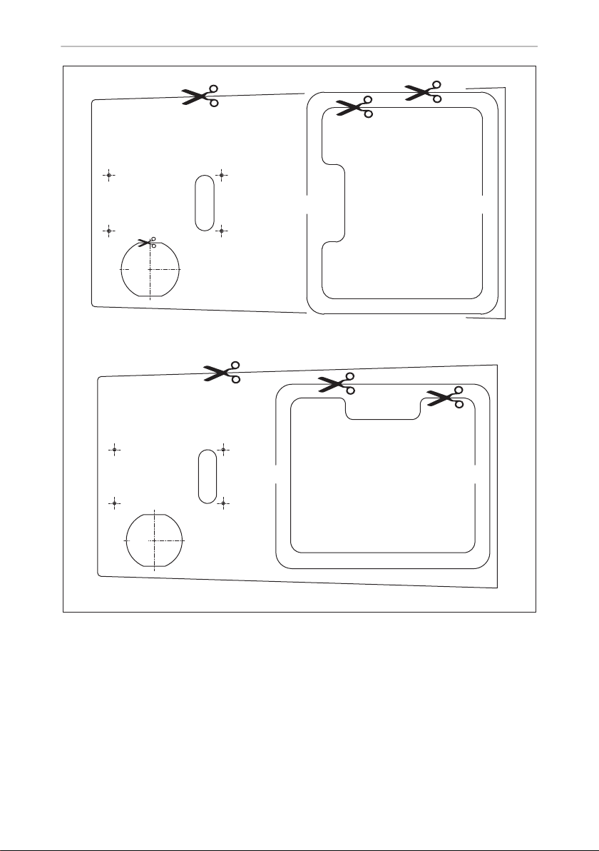
For the Saneo BW and Saneo CW models, mount a tank flap for the integrated water
tank.
➤ Using the template (fig. 3 1, page 4) create an opening in the outer wall. The
template is greatly reduced in size in the instructions. For the original, see the
packaging.
You can find the installation description of the tank flap in chapter “Installation of the
tank flap” on page 27.
23
Page 24

EN
Installing the toilet Saneo B, Saneo C
5.3 Setting up the toilet
NOTICE!
A
➤ Install the toilet according to the description for the respective model version.
➤ Set up the toilet so that it is flush to a vertical wall only.
➤ Leave at least 60 mm space to the side walls so that the swivelling of the upper
part of the toilet (with seat) is not restricted.
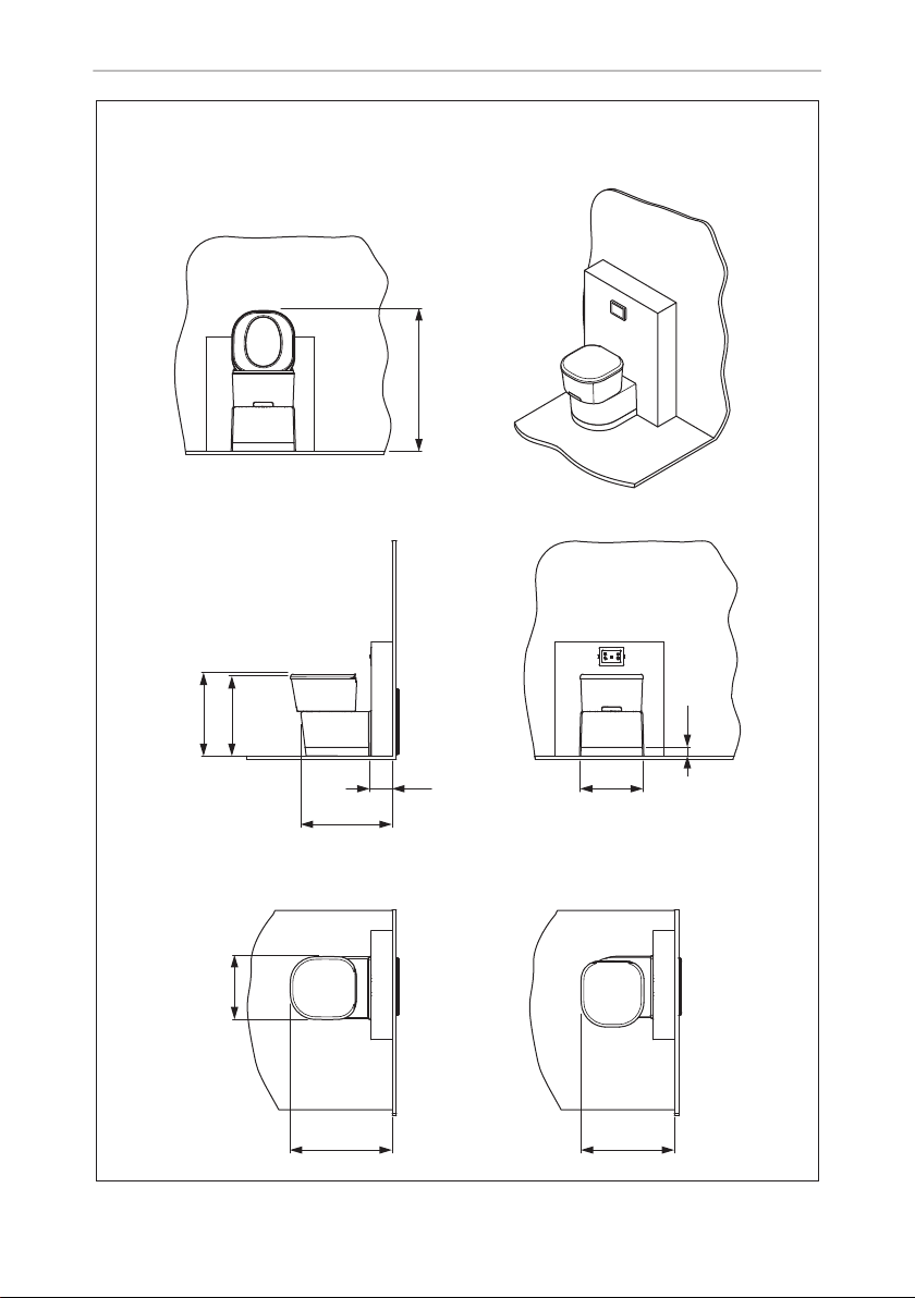
➤ For the installation, use the dimensional drawings and templates:
– Saneo B, Saneo C: fig. 4, page 5
– Saneo BS, Saneo CS: fig. 5, page 6
– Saneo BW, Saneo CW: fig. 5, page 6
– Saneo BLP, Saneo CLP: fig. 6, page 7
– Milling dimensions: fig. 7, page 8
– Drill holes: fig. 8, page 9
– Radii: fig. 9, page 10
I
All components of the system must be installed in frost-free areas.
In freezing temperatures, there is a risk of damage caused by frost.
NOTE
• For the templates for milling dimensions, drill holes and radii,
observe the symmetry point of the toilet (fig. 7 A, page 8,
fig. 8 A, page 9, fig. 9 A, page 10).
• When installing the toilet in a wet room, the manufacturer recommends that you connect the toilet to the shower tray.
5.4 Setting up the Saneo B, Saneo C toilet
The freestanding models Saneo B and Saneo C have no integrated water tank. Set
up this model so that the wall behind it can accommodate the control unit of the
toilet, the electrical connections and possibly a water tank. It is ideal if you put a box
in front of the room wall (fig. 0, page 11).
NOTE
I
24
Exemplary installation in a shower tray is shown in fig. 0, page 11 and
fig. a, page 11.
Page 25

EN
Saneo B, Saneo C Installing the toilet
Note that the cassette protrudes 112 mm out of the cassette housing (fig. a,
page 11).
➤ Place the housing base (fig. a 1, page 11) flush with the installation frame of the
service door (fig. a 2, page 11) so that there is a clean transition and no gap.
Anchoring the Saneo B, Saneo C toilets
➤ Place the toilet in the desired position.
➤ Tightly fasten the base plate with four screws (fig. b 2, page 12).
➤ Insert the caps (fig. b 1, page 12).
➤ Then bolt the toilet housing to the wall (using a maximum of 4 bolts, not included)
(fig. c, page 12).
NOTE
I
➤ Slide in the mobile tank cassette (fig. i, page 15).
Installation of the control and operating panel of the Saneo B, Saneo C
toilets
1:1 template available from the manufacturer.
Install the control and operating panel in the wall in the immediate vicinity of the toilet
at an easily accessible location.
➤ For the control and operating panel, create an opening in the wall using the true-
to-scale template (fig. d, page 13).
➤ Connect the electrical cables to the couplings for installation of the operating and
control panel (chapter “Electrical connection” on page 28).
CAUTION!
!
➤ Press the retaining springs of the control and operating panel in and push it into
the wall cutout (fig. e, page 14).
There is a risk of injury due to the springs springing back!
25
Page 26

EN
Installing the toilet Saneo B, Saneo C
5.5 Setting up the Saneo BW, Saneo CW, Saneo BS,
Saneo CS, Saneo BLP, Saneo CLP toilets
These models have a wall connection console. The control and operating panel is
integrated in the wall connection console.
Models Saneo BW and Saneo CW feature a built-in water tank, while models
Saneo BS and Saneo CS do not have a water tank.
Set up all models with wall connection console directly against the room wall
(fig. f, page 14). A previously attached wall bracket is used to secure the toilet and
the wall bracket.
➤ Screw on the wall bracket, level, at the following height (fig. g, page 14):
Variant A:
Model A B C D
Saneo BW, Saneo BS 170 mm 96 mm 645 mm 652 mm
Saneo CW, Saneo CS 170 mm 96 mm 645 mm 652 mm
Saneo BLP, Saneo CLP 170 mm 96 mm 462 mm 469 mm
Variant B:
– Saneo BW, Saneo BS: h = 661 mm
– Saneo CW, Saneo CS: h = 661 mm
– Saneo BLP, Saneo CLP: h = 478 mm
➤ Put the entire toilet module into the desired position in front of the wall bracket.
➤ Lift the toilet and hook the housing into the wall bracket (fig. h, page 15).
➤ Tightly fasten the base plate with four screws (fig. b 2, page 12).
➤ Insert the caps (fig. b 1, page 12).
➤ Slide in the mobile tank cassette (fig. i, page 15).
5.6 Water connection
NOTE
I
➤ Connect the water supply using a smooth hose connection (fig. j 1, page 16).
The connection socket is not included in the scope of delivery.
For the Saneo xW models with an integrated water tank, the water connection is installed at the factory.
26
Page 27

EN
Saneo B, Saneo C Installing the toilet
➤ Perform a leak test.
NOTICE!
A
Performing a measurement to test the flushing output
I
For performing a measurement to test the flushing output, there are two variants:
Variant 1:
➤ Disconnect the hose connection of the toilet from the vehicle line.
➤ Place the open end of the line into a bucket.
➤ Actuate the flushing for 1 minute using the toilet operating unit.
➤ Measure the volume of water in the bucket.
The volume of water that is in the bucket corresponds to the water flow rate in
l/min.
The operating pressure (water pressure) of the solenoid valve should not
exceed 6 bar.
The solenoid valve is damaged by excessive pressure.
NOTE
Water supply (vehicle-side pump):
The toilet requires a min. of 7 l/min provided by the vehicle at the outlet
of the hose connection of the toilet in order to ensure satisfactory flushing output of 5 l/min.
Variant 2:
➤ Disconnect the hose connection of the toilet from the vehicle line.
➤ Connect a Gardena water meter to the toilet water line.
➤ Actuate the flushing using the toilet operating unit.
➤ Read the water flow in l/min on the Gardena water meter.
5.7 Installation of the tank flap
For the Saneo BW and Saneo CW models, mount a tank flap for the integrated water
tank.
➤ Using the template (fig. 3 1, page 4) create an opening in the outer wall.
➤ Seal the tank flap water tight (for example, with butyl rubber).
27
Page 28

EN
Electrical connection Saneo B, Saneo C
➤ Put the tank flap on the tank.
➤ Tightly fasten the tank flap with four C4x25 countersunk screws (not included).
➤ Slide the O-ring onto the inner tube of the tank flap (fig. k, page 16):
– A: Position of the O-ring with a wall thickness of 30 mm – 50 mm
– B: Position of the O-ring with a wall thickness of 20.5 mm – 30 mm
➤ Grease the O-ring. This makes it easier for the filler neck to be connected with the
upper part of the tank.
6 Electrical connection
WARNING!
!
A
The electrical system must be wired by qualified personnel.
NOTICE!
• Do not connect the toilet to the voltage supply directly in parallel
with other power-consuming devices.
• Do not connect the control of the toilet to a pressurised water pump.
• The rated capacity of an external water pump must not exceed
100 W.
NOTE
I
Key for fig. l, page 17:
Item Label
1Toilet
2 Water pump
3 Switch
4 Fuse/main terminal box
512 V supply
28
• The external water pump is not included in the scope of delivery.
• A pre-fuse is not necessary, because the toilet is internally fused.
Page 29
EN
Saneo B, Saneo C Electrical connection
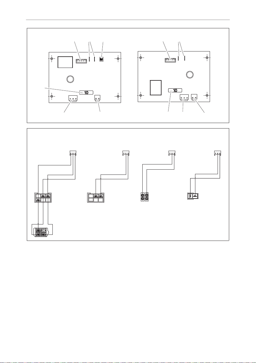
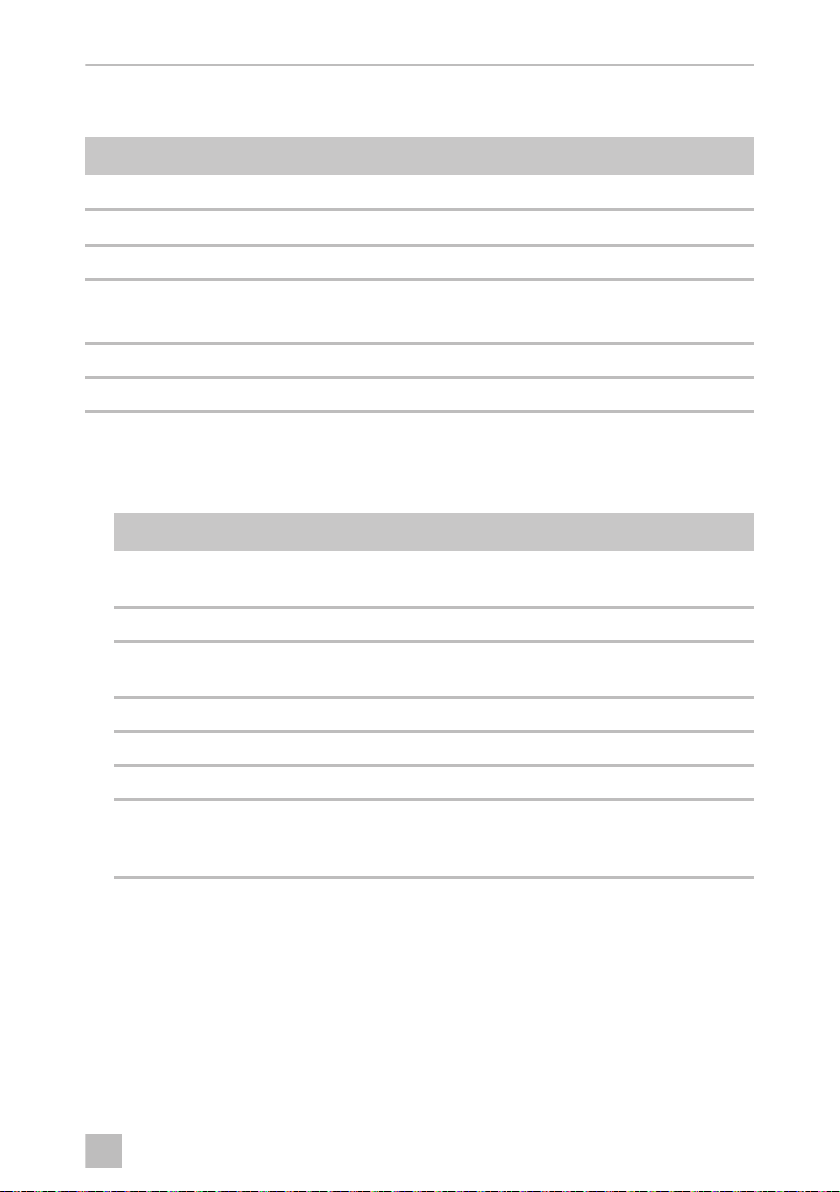
The layout of the touch-switch control unit (fig. m A, page 18) and of the tact-switch
control unit (fig. m B, page 18) is as follows:
Item Label
1 5-pin connector for Reed sensors cassette tank and micro-switch cassette
2
Only Saneo BW, CW
3 Jumper (only touch-switch control unit)
4
Only Saneo B, C, BS, CS, BLP, CLP
Only Saneo BW, CW
512 V supply
6Fuse (10A)
: Float level indicator, water tank
: Valve connection
: Internal pump connection
➤ Connect the toilet via the main terminal block of the vehicle to its own power
supply (fig. l, page 17 and fig. m 5, page 18). Use the corresponding cable
(fig. n, page 18):
Pos./cable colour Label
A Saneo B, BS, BLP, C, CS, CLP
(do not use when using a pressurised water pump)
B Saneo BW, CW
C Saneo B, BS, BLP, C, CS, CLP with pressurised water pump
(Australia)
D Saneo BW, CW (UK)
wt White cable, earth (–)
rt Red cable, input (+)
bl Blue cable, output (+)
Control line for an external pump
(do not use when using a pressurised water pump)
29
Page 30
EN
Technical data Saneo B, Saneo C
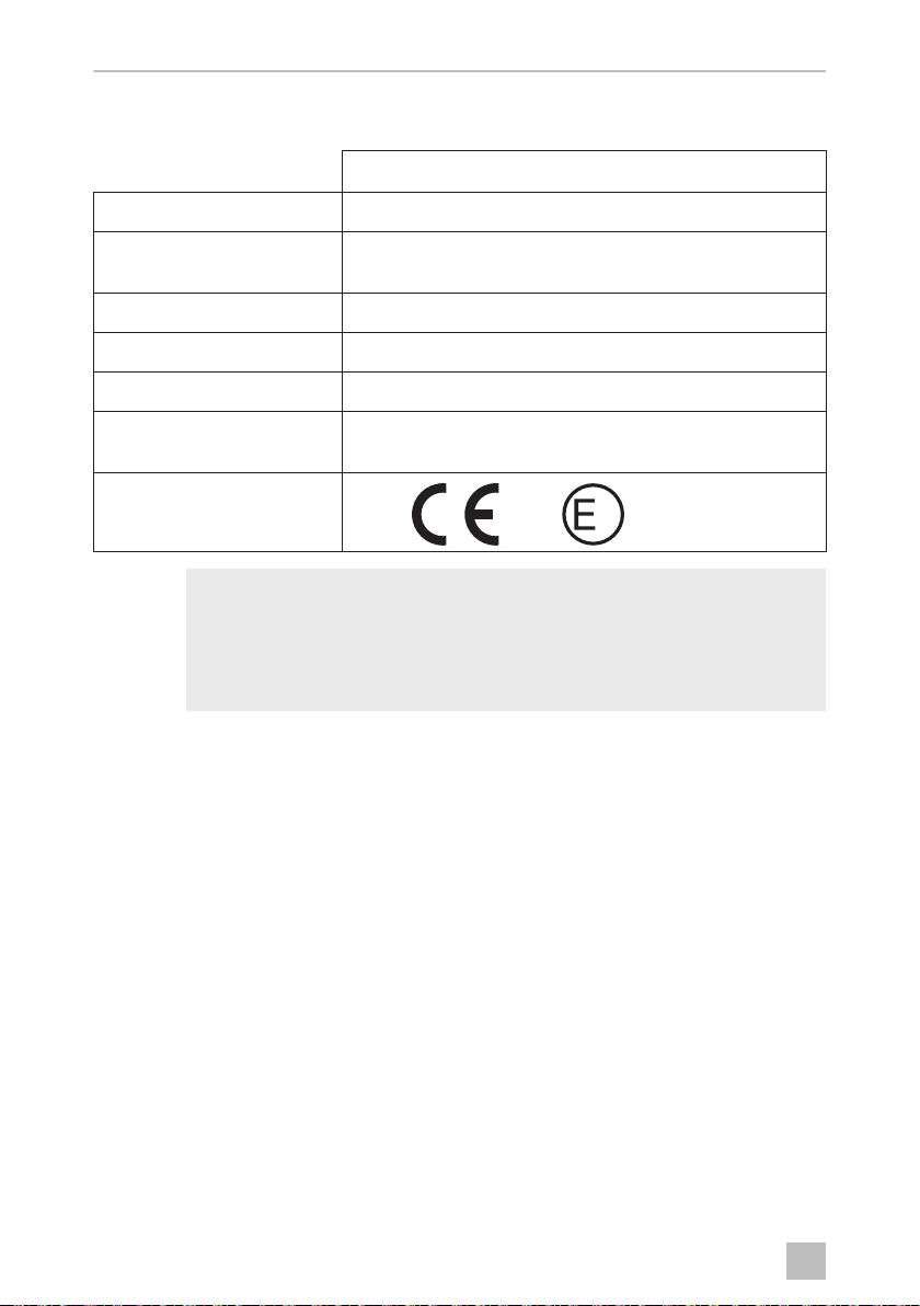
7Technical data
Dometic Saneo
Input voltage
Current consumption
Max. person weight
Dimensions
Operating temperature
Capacity
Test mark
I
:
:
:
:
NOTE
Water supply (vehicle-side pump):
The toilet requires a min. of 7 l/min provided by the vehicle at the outlet
of the hose connection of the toilet in order to ensure satisfactory flushing output of 5 l/min.
12 Vg
:
:
:
Max. 2 A with internal pump
Max. 10 A with external pump
150 kg
See fig. 4, page 5 to fig. 9, page 10
0 °C to +50 °C
16 l (cassette tank)
7 l (freshwater tank, optional)
N1 10 R – 047317
1
30
 Loading...