

Page 1
PROCEDURE FOR
®
CHANGING COOLING UNIT
IN CARAVAN 95 AND NDR
REFRIGERATORS
Refrigerator
Bulletin R74/6D
March 2002
The following categories have been established predicated on similarity of design and procedure for
replacement of cooling units:
A - CATEGORY #1
RM2193 RM2332 RM2333
RM2452 RM2453 RM2551
RM2552 RM2553 RM2554
RM4223 RM4290 RM4292
B - CATEGORY #2
RM2620 RM2652 RM2820
RM2852 RM3662 RM3663
RM3862 RM3863 NDR1062
C - CATEGORY #3
RM1272 NDR1282
RM1282 NDR1292
NDR1272 NDR1492
GENERAL INSTRUCTIONS TO ALL MODELS
1. Disconnect shore power from coach, the positive lead
from battery, and turn propane OFF at the tank.
These instructions must be read and understood before installation of this kit. This kit must
be installed by a Dometic service center or a
qualified service technician. Modification of this
product can be extremely hazardous and could
result in personal injury or property damage.
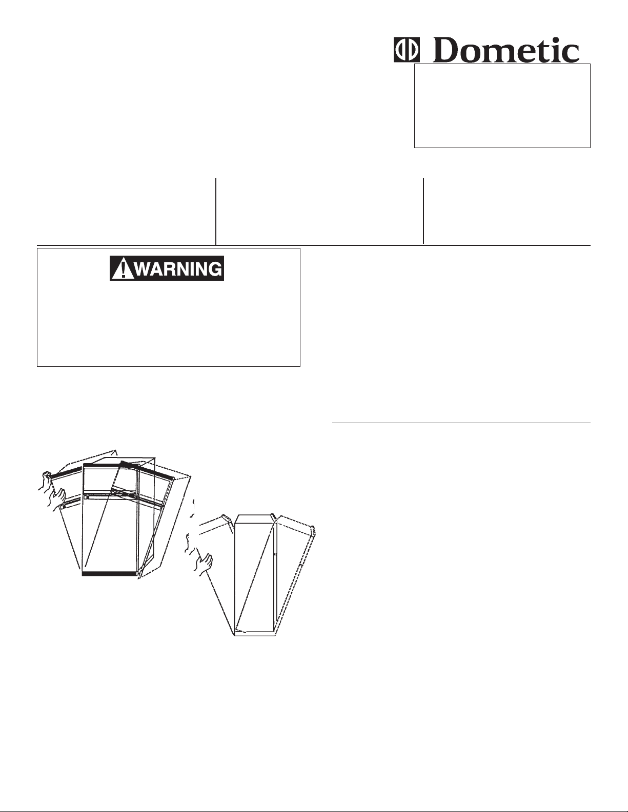
Important: After the cooling unit has been installed,
the initial start-up time can be shortened by tilting the
refrigerator from side-to-side and then from front-toback before the refrigerator is turned on. Hold in each
tilt position for approximately 30 seconds to settle
solution to bottom of cooling unit.
2. Through lower vent, unplug refrigerator 120V AC cord(s)
from wall receptacle. Disconnect 12V DC wires from
terminal block on the refrigerator (if models have 12V
DC). Tape or cap ends.
3. Check again to make sure propane is OFF at tank, then
remove coach gas line from gas cock on refrigerator and
cap coach gas line.
4. For Models with Ice Maker: Turn water OFF to
appliance. Disconnect coach’s water line from water
solenoid (cap end).
5. Remove the refrigerator from alcove.
A. Category #1:
RM2193 RM2332 RM2333 RM4223
RM2452 RM2453 RM2551 RM4290
RM2552 RM2553 RM2554 RM4292
TILT FRONT-TO-BACK
TILT SIDE-TO-SIDE
Run the refrigerator on a bench for 12 hours after the cooling
unit has been installed. The refrigerator should not have food
in it during this test.
REVISION
Form No. 3107154.035 3/02
(Replaces 3107154.027)
©2002 Dometic Corporation
LaGrange, IN 46761
STEP 1. REMOVAL OF COOLING UNIT
1. See General Instructions on all models.
2. Loosen screws holding the thermostat bulb to fins. See
FIG. A1.
Note: Some models have a plastic thermistor bracket
clipped to the fin.
3. Remove the screws from the back wall of the freezer and
the fins.
Note: On models RM2452, RM2453, RM2551, RM2552,
RM2553 and RM2554, the fins are installed on the cooling
unit before it is put in the cabinet. The cooling unit must be
out of the cabinet before the fins can be removed.
4. On all other models remove the fins. See FIG. A1.
5. Lay the refrigerator face down on two 2x4’s to avoid
damaging the refrigerator front.
6. Remove cover from boiler and heating element(s).
7. Remove burner cover and then the burner assembly.
Note: Some models have a bracket that holds the manual
gas cock and/or the electric solenoid valve. Remove the
screws from these brackets and save to be reinstalled.
8. Cut the wire ties along the left side. Remove the
thermostat sensor tube (if required) and position the
burner assembly and wires so they will not be damaged
1
by pulling the cooling unit.
Page 2
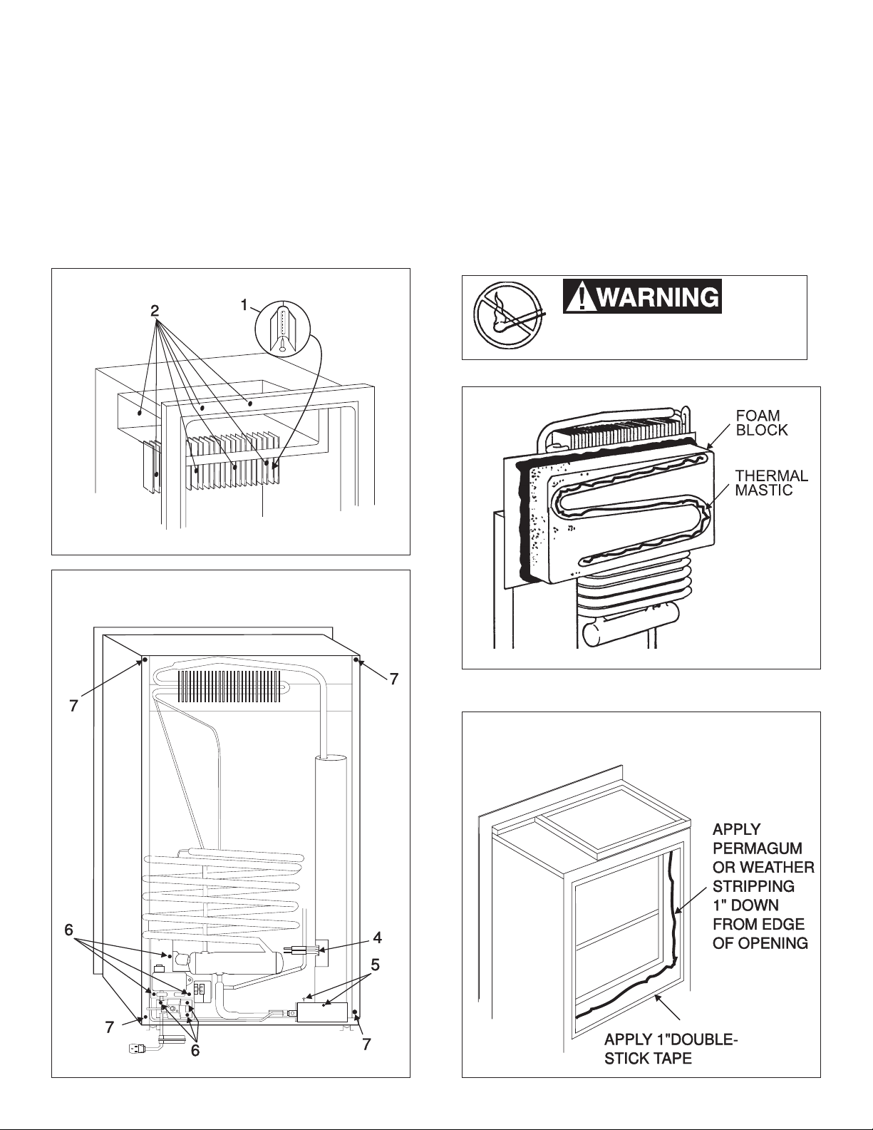
STEP 2. INSTALLATION OF COOLING
UNIT
1. Inspect cooling unit for broken welds or bent frame.
2. Trim the foam block portion of cooling unit if it does not
go freely into the refrigerator. Be sure foam does not
cover the evaporator tubes where cooling fins attach.
3. Apply thermomastic on evaporator tubes 1/4” to 3/8”
bead. Apply more if the tubes are recessed in foam
block. (FIG. A3)
4. Apply permagum and double-stick tape to cabinet as
shown in FIG. A4.
FIG. A1
5. If foam block fits loosely into cabinet (1/4” or more of
movement) use 1/2” wide x 3/8” thick closed cell, onesided adhesive weather stripping. Place in the same
location as permagum. Also apply double-stick tape as
shown in FIG. A4.
6. Install cooling unit back in the cabinet. Replace screws
holding cooling unit to cabinet. Replace components
removed in Step 1, 587. (FIG. A2)
7. Stand refrigerator upright. Transfer flue baffle to new
cooling unit. Replace the inside parts removed in Step 1,
2–4. (See “Important” on Page 1).
8. Install refrigerator back into coach and leak check all gas
fittings. Repair all gas leaks.
Do not use a flame
to check for gas leaks.
FIG. A3
FIG. A2
FIG. A4
2
Page 3
B. Category #2
RM2620 RM2652 RM2820 RM2852
*RM3662 *RM3663 *RM3862 *RM3863
*NDR1062
* Optional Ice Maker Cycle
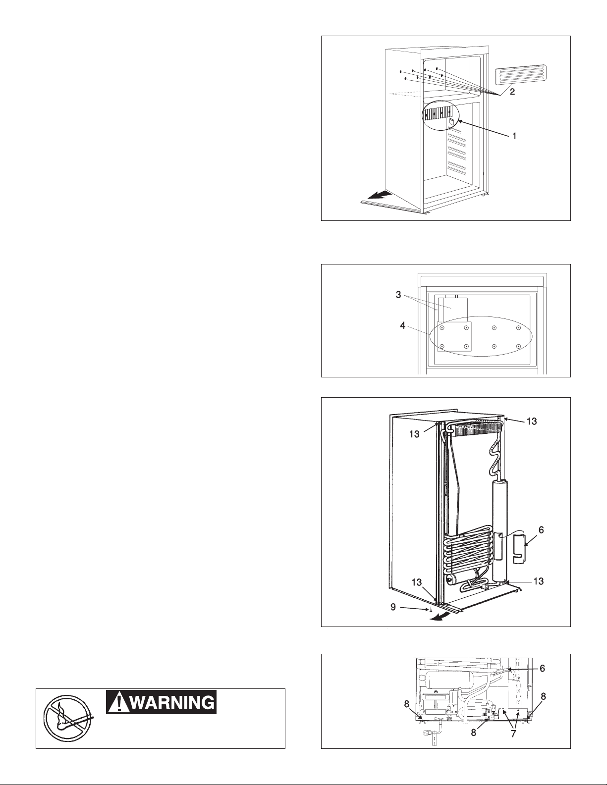
STEP 1. REMOVAL OF COOLING UNIT
1. See General Instructions for all models.
2. Remove thermistor bracket and 4 screws from fins (FIG.
B1). DO NOT remove fins. They are taped to the rear of the
cabinet liner.
3. In the freezer, remove shelves and grill covering screws.
Pull out center of grill to allow right or left side to pop out
of slot (FIG. B1).
4. Models with Ice Maker: Remove the cover of cycle and
the 2 screws holding cycle to the side wall (FIG. B2).
5. Remove 4 screws holding cycle bracket. Be careful not to
drop. Unplug electrical connection and take cycle out of
freezer. Remove the remaining screws. (FIG. B2)
6. Lay the refrigerator face down on two 2x4’s to protect the
face of the appliance.
7. Remove heater cover and heater(s) (FIG. B3 & B4). Also
disconnect ice wire harness leads from electrical connections on the refrigerator.
Note: NDR models - pull wire harness out of the cooling unit
from the inside of freezer. Pull water fill tube from rear of
refrigerator. Disconnect water line from water solenoid valve.
8. Remove burner cover (1 screw) and screw holding the
burner to flue tube. Pull burner down and off tube (FIG. B4).
9. Remove 2 screws holding control panel to runner and 2
screws holding gas solenoid valve to cooling unit (FIG. B4).
10. Take out screws (1 on each side) where runner fastens to
the rear of cabinet. Swing runners out to the side to clear
cabinet (FIG. B3).
11. Cut wire ties holding cables and thermistor to frame of
cooling unit.
12. Disconnect climate control and interior (red wires) from J2
on circuit board and black wires from ground.
13. Cut red and black wires from interior light. Strip back 3/8”
to reconnect using butt connectors after cooling unit has
been installed.
14. Remove 4 screws holding cooling unit to cabinet (2 on top
and 2 on bottom). (FIG. B3). Lift cooling unit out of cabinet.
FIG. B1
FIG. B2
FIG. B3
STEP 2. INSTALLATION OF COOLING UNIT
1. Refer to Step 2, Category A, 1–5.
2. Install cooling unit back in cabinet. Replace screw holding
unit.
3. Replace the components removed in Step 1, 2-14.
4. Stand refrigerator upright. Transfer the flue baffle to new
cooling unit. Replace inside parts removed in Step 1, 2–5.
5. Check for proper cooling before installing refrigerator back
into the coach. (See “Important” on Page 1).
6. Install refrigerator back into coach and leak check all gas
fittings. Repair all gas leaks.
Do not use a flame
to check for gas leaks.
FIG. B4
3
Page 4

STEP 3. PREPARING THE COOLING UNIT
SPREAD ATHIN
LAYER OF
THERMOMASTIC
ON ICE MAKER SHELF
FOR THE ICE MAKER (For only models with ice maker)
Note: Models that have the water fill for the ice maker entering
through the top do no require drilling of cooling unit
(RM3652, RM3653, RM3862, and RM3863). The cooling unit has been installed in the refrigerator, proceed to
number 2.
1. Before the shelves and other interior parts are placed into
the cabinet, the opening for the ice maker water lines and
power cords must be made through the foam block of the
cooling unit. Look at the defective cooling unit to determine
the approximate location and angle to drill the hole in the
new cooling unit. The two holes are drilled from the interior
of the cabinet out through the rear of the refrigerator. Use
a 1/2” and 3/4” by 8” long drill bit to make the two holes. Be
careful not to drill into any refrigerant lines, causing a leak.
See FIG. B5.
2. The wire harness is routed from the inside of the freezer
compartment through the 1/2” hole. Pull the wire harness
through the back wall of the freezer compartment. Leave
sufficient length of wires (approx. 8”) to connect to the
cycle. Follow the same path that was used before by the
wire harness and reconnect it to the solenoid and power
cord.
3. Route the water line from the water solenoid up the rear of
the refrigerator. Insert the fill tube from the rear through the
3/4” hole. Use permagum to make an air tight seal around
the wire harness and water fill tube. If water line is not
attached to the fill tube it should be connected now. Make
sure that the same routing is followed between the water
solenoid and fill tube. If the water line has heat tape, be
sure it is in place. Use aluminum foil tape to cover and seal
the water line and wire harness to the back of the cabinet.
See FIG. B6.
4. Spread a thin layer of thermomastic on ice maker shelf.
See FIG. B7. Plug the wire harness to the ice cycle. Install
the cycle using the screws removed. Make sure the end
of the water fill tube will allow water to enter the cycle inlet,
and is free from touching the sides or bottom. This will
allow the water to drain completely out of the fill tube and
prevent freezing.
5. Return to Step 2 (Installation of cooling unit), #3 of this
section.
FIG. B5
FIG. B6
FIG. B7
SPREAD ATHIN
LAYER OF
THERMOMASTIC
ON ICE MAKER SHELF
4
Page 5

C. Category #3
NDR1272 **NDR1282 NDR1292
NDR1492 RM1272 **RM1282
** (Ice Maker Cycle/Compressor Operated)
STEP 1. REMOVAL OF COOLING UNIT
1. See General Instructions for all models.
2. Remove the two top shelves and drip tray. Disconnect
interior light from side of refrigerator. Remove thermistor
with bracket from fins (FIG. C1).
3. Remove cooling fins - right side first (6 screws). Pull
out drain cup and remove tube (FIG. C1).
4. Models with Ice Maker: Remove cycle from shelf
plate (3 screws) (FIG. C2). Lift cycle off shelf. Unplug
the cable and move out of cabinet until you are ready
to reinstall. Disconnect the electrical cable from back
of refrigerator and pull out from inside.
5. All Models: Follow Steps 5 – 11.
6. Remove freezer plates (FIG. C3).
A.Two screws with nuts (hexagon)
B.Two screws (side)
C.Two screws (top)
D.Two screws (side)
7. After freezer plates are re moved, take out 4 screws
holding the cooling unit to circulation tube (FIG. C3).
Remove plastic cover plate on the back of freezer.
8. Lay refrigerator face down on two 2x4’s to protect
handles and frame from damage.
9. Removal of controls at rear of refrigerator (FIG. C4).
A.Two screws (plate protections)
B.Two screws (mounting plate circuit board
- (not shown)
C.Three screws (gas valve bracket)
D.Three screws (burner assembly -
not shown)
10. Remove heater cover, heaters (2) and any
other parts that interfere with the removal
of cooling unit.
Note: Before cooling unit is placed in the
refrigerator cabinet, check the tapped screw
holes. See FIG C3 #6. Paint can fill the
holes and make replacement of screws
impossible. See FIG. C4.
11. Remove screws holding cooling unit to the
cabinet (5).
12. Apply leverage as shown and pull out (FIG. C4).
13. Remove the ground wire (white) from bottom of old
cooling unit and place on new one.
STEP 2. INSTALLATION OF COOLING UNIT
1. Refer to section A Category #1, Step 2, 1–5.
2. Place cooling unit in cabinet and replace screws.
3. Replace components removed in Step 1, 9–11, FIG.
C4.
4. Stand refrigerator upright. Transfer flue baffle to the
new cooling unit. Replace inside parts removed in
Step 1, 2–4.
5. Check for proper cooling before installing refrigerator
back into coach. (See “Important” on Page 1).
6. Install refrigerator back into coach and leak check all
gas fittings. Repair all gas leaks.
Do not use a flame
to check for gas leaks.
FIG. C1
FIG. C3
FIG. C4
FIG. C2
5
Page 6

STEP 3. PREPARING THE COOLING UNIT
APPLY
THERMO
MASTIC
TO TOP
FOR THE ICE MAKER (Models with
ice makers)
1. Models with compressor assist ice making, require a
groove to be cut in the foam block to allow a path for the
refrigerant line and wire harness. This groove needs to
be present before the cooling unit can be fitted into the
cabinet. Models without the compressor should proceed to number 6.
2. The cooling unit frame is manufactured with a notch cut
into it. This notch is where the refrigerant line and wire
harness will pass through once the foam block is cut
away. Use a hacksaw and make the groove on the right
hand side of the foam block. The groove should be the
same dimensions as the notch in the frame. See FIG.
C5 & C7.
3. The cooling unit can be installed into the refrigerator.
See Section A, Category #1, Step 2, 1-5.
4. Before the shelves and other interior parts are placed into
the cabinet, the opening for the ice maker water line must
be made through the foam block of the cooling unit. Look
at the defective cooling unit to determine the approximate location and angel to drill the hole in the new
cooling unit. The hole is drilled from the interior of the
cabinet out through the rear of the refrigerator. Use a 3/
4” by 8” long drill bit to make the hole. Be careful no to
drill into any refrigerant lines, causing a leak. See FIG.
C6.
5. Proceed to number 8.
6. Models without compressor, the cooling unit can be
installed into the refrigerator. Before the shelves and
other interior parts are placed into the cabinet, the
opening for the ice maker water lines and power cords
must be made through the foam block of the cooling unit.
Look at the defective cooling unit to determine the
approximate location and angel to drill the hole in the new
cooling unit. The two holes are drilled from the interior of
the cabinet out through the rear of the refrigerator. Use
a 1/2” and 3/4” by 8” long drill bit to make the two holes.
Be careful not to drill into ant refrigerant lines, causing a
leak. See FIG. C6.
7. The wire harness is routed from the inside of the freezer
compartment through the 1/2” hole. Pull the wire
harness through the back wall of the freezer compartment. Leave sufficient length of wires (about 8”) to
connect to the cycle. Follow the same path that was
used before by the wire harness and reconnect it to the
solenoid and power cord.
8. Route the water line from the water solenoid up the rear
of the refrigerator. Insert the fill tube from the rear through
the 3/4” hole. Use permagum to make an air tight seal
around the wire harness and water fill tube. Seal both the
outside and inside. If the water line is not attached to the
fill tube it should be connected now. Make sure that the
same routing is followed between the water solenoid and
fill tube. If the water line has heat tape, be sure it is in
place. Use aluminum foil tape to cover and seal the water
line and wire harness to the back of the cabinet. See
FIG. C7.
9. Spread a thin layer of thermomastic on top of the ice
maker shelf. See FIG. C8. Plug the wire harness to the
ice cycle. Install the cycle using the screws removed.
Make sure the end of the water fill tube will allow water
to enter the cycle inlet, and is free from touching the
sides or bottom. This will allow the water to drain
completely out of the fill tube and prevent freezing.
10. Return to Section C, Category #3, Step 2, #3.
FIG. C5
FIG. C6
FIG. C7
FIG. C8
APPLY
THERMO
MASTIC
TO TOP
6
Page 7

This manual has been provided courtesy of
DARREN KOEPP - OWNER, MY RV WORKS, INC.
www.myrvworks.com
You can find more RV service manuals here:
www.myrvworks.com/manuals
My RV Works, Inc.
Over the years of running a mobile RV repair service, having a dedicated place
to access service manuals for all the different appliances and components
found on RVs was something that I always had a desire to create.
I hope this resource makes your RV repairs easier, as it has mine, but please
be careful and follow proper safety practices when attempting to repair
your own RV.
If in doubt, please consult with a professional RV technician!
All service manuals provided on www.myrvworks.com are believed to be
released for distribution and/or in the public domain.
 Loading...