

Page 1
•Americana /Americana Plus
•Classic
•New Dimensions
•New Generations
Page 2
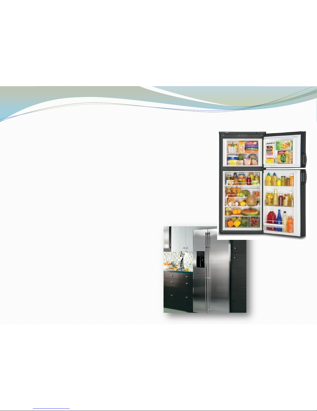
Home Refrigerators
vs
RV Refrigerators
• Compressor vs Absorption
• Controlled Environment vs
Changing Environment
• Recovery time is vastly
different
30-45 minutes vs
1-2 hours recovery
Page 3
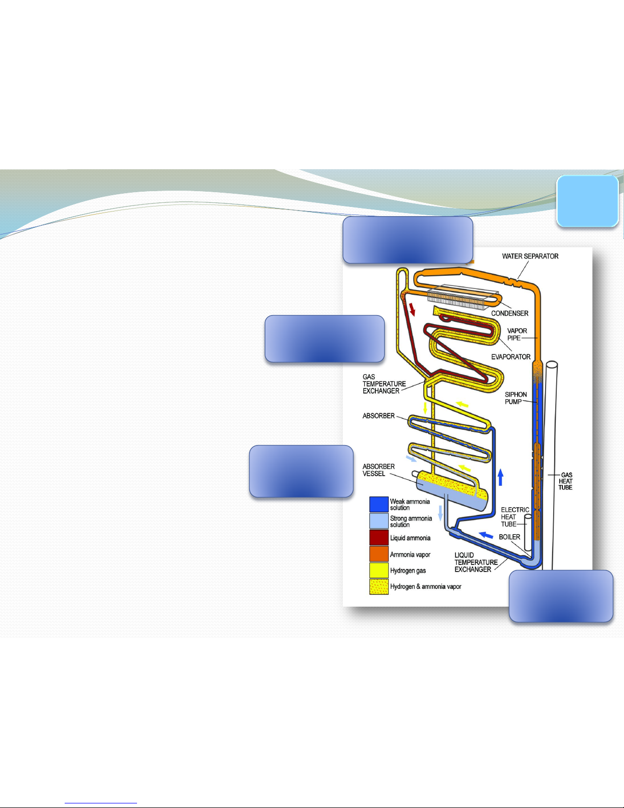
CONDENSER
EVAPORATOR
ABSORBER
BOILER
SOLUTION IS
MADE UP OF:
•AMMONIA
•WATER
•HYDROGEN
•RUST INHIBITOR
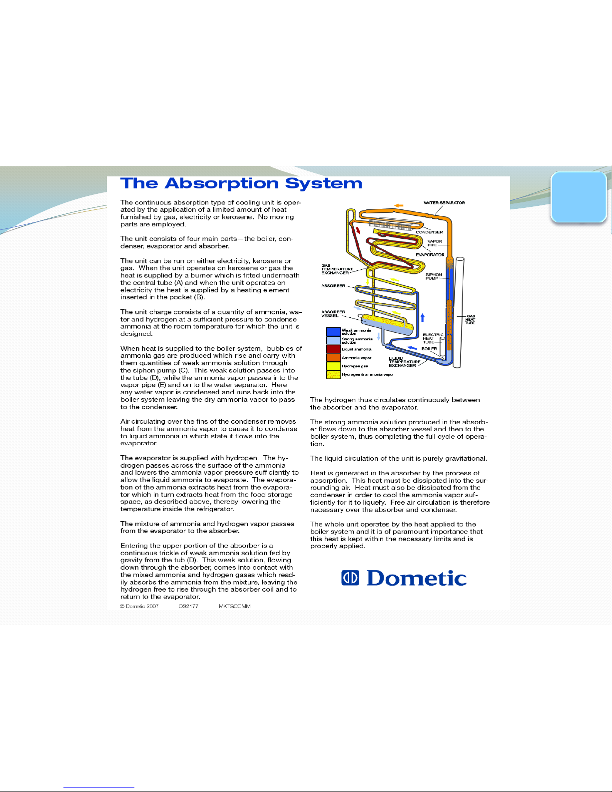
The
Absorption
System
PG.
26
Page 4
PG.
25
Page 5
To properly test a Cooling Unit
Three criteria have to be met:
•Level ?
•Ventilation ?
•Heat Source?
Page 6
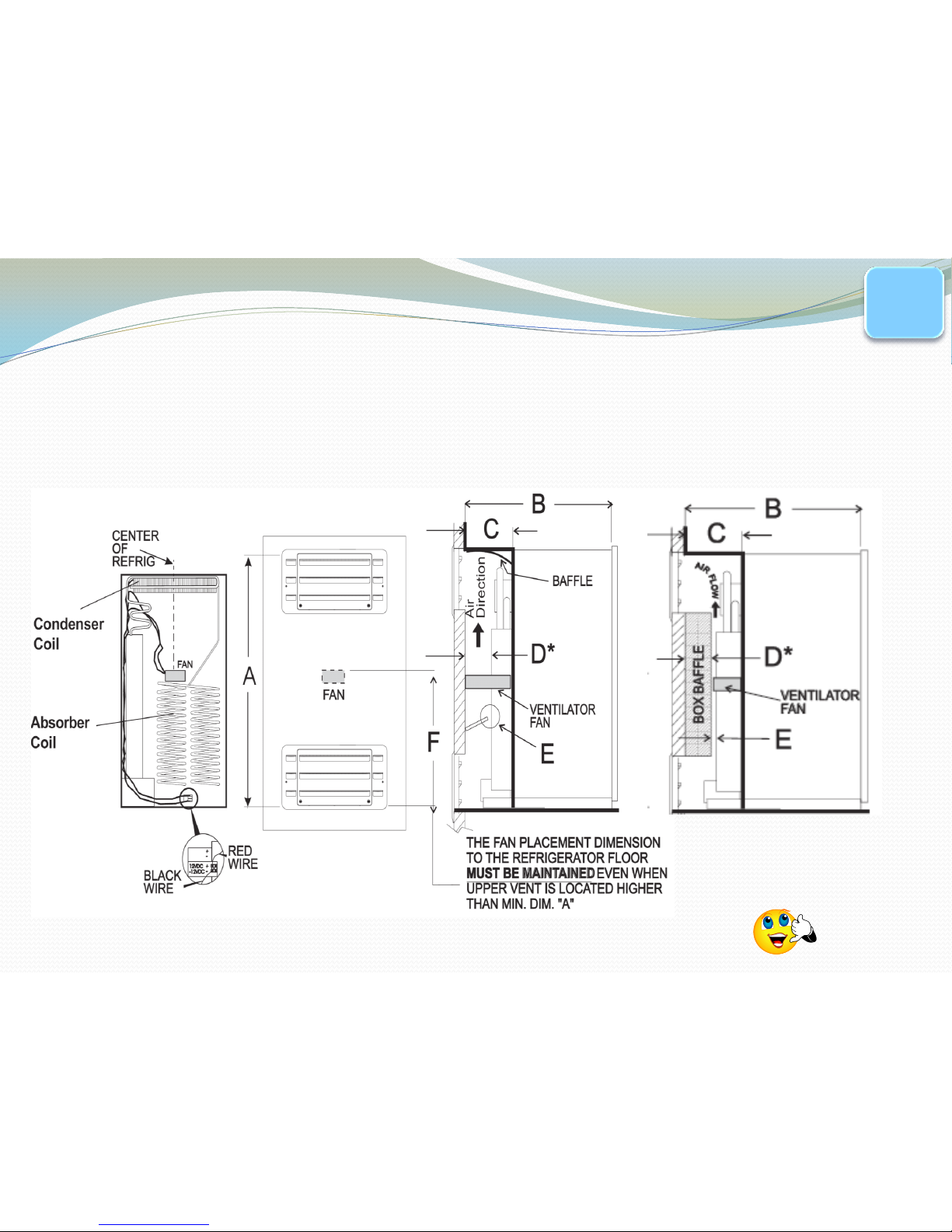
Ventilation
Make sure you check Ventilation and Air Flow
-0” clearance on the sides and top
-No more than 1” from back of CU to
sidewall. (A baffle may need to be installed to
help direct air across coils)
-If there is an auxiliary fan, check that it is
working properly.
PG.
21
Page 7
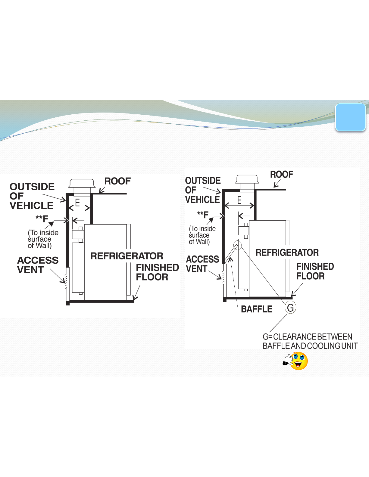
Typical Double Door Install
0” clearance on the side and
top and less than 1” from CU
to sidewall
Application Guide 3308666.XXX
PG.
21
Page 8
Typical Side by Side Installation
in Slide Out/2 Sidewall Vents
Application Guide 3308666.XXX
PG.
21
Page 9
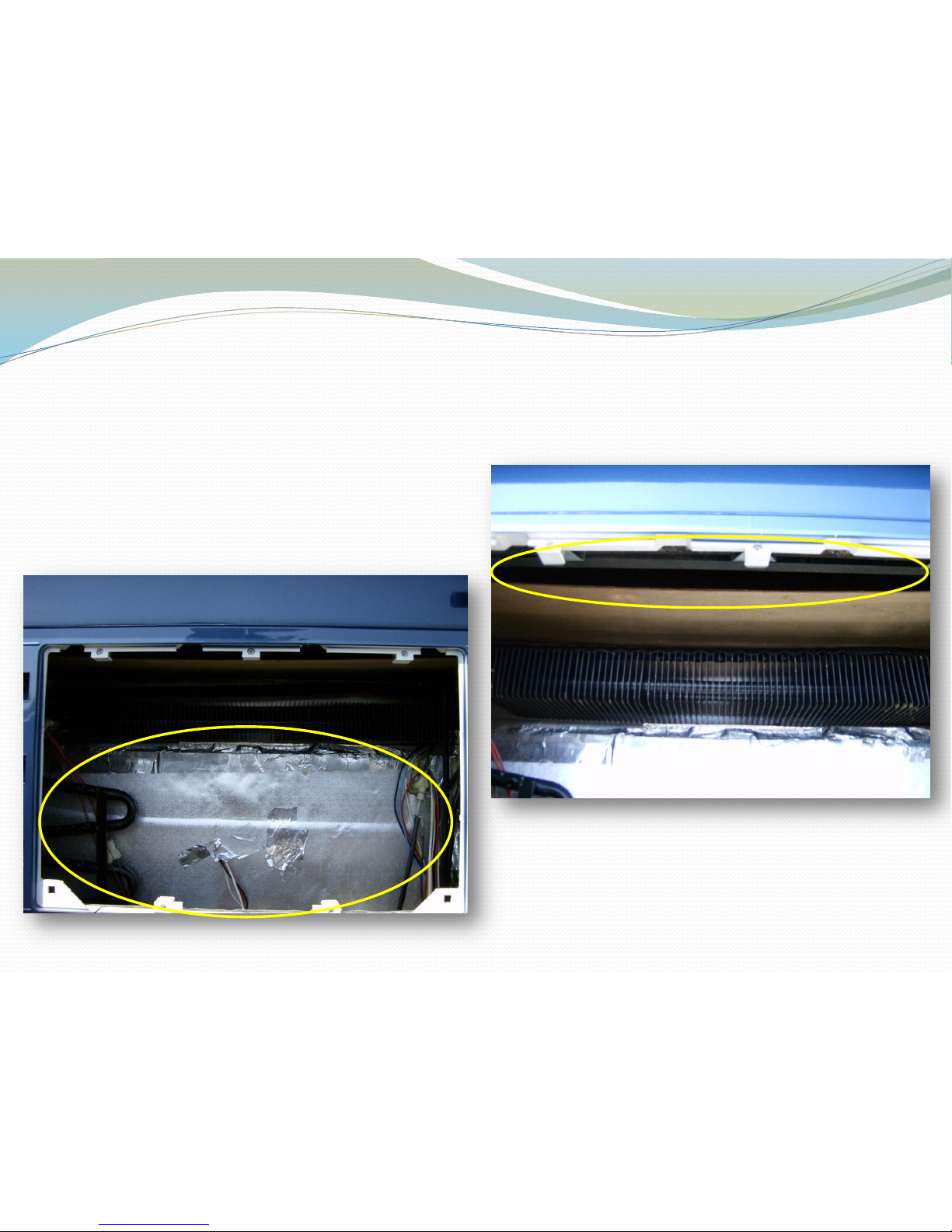
Symptom: Not Cooling
Air is not being forced through the
condenser – to much space!
Warm air is being trapped around
the refrigerator from a poor
installation.
Page 10
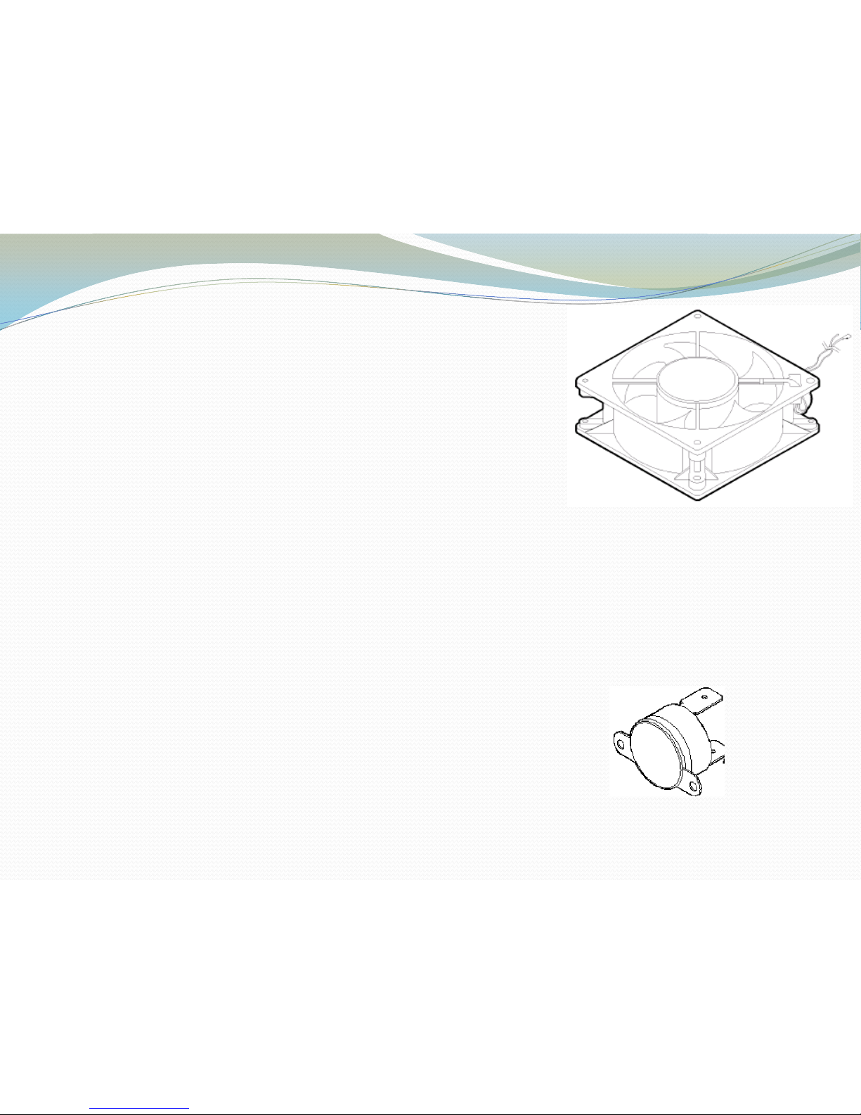
AUXILIARY FANS
Helps with air flow.
3108705.751 for Single Door refers
Fan limit switch will close at 105°F and open at
90°F +/- 10%.
3108705.744 for Double Door refers
Fan limit switch will close at 150°F and open at 120° +/-
10%.
Will draw only .5 amps each.
In-line fuse to protect circuit
Small Fan # 3851183016
Note: Please write these Part #’s down as they are not in the service manual.
Limit Switch only: 3104723.006
Limit Switch only: 3104133.016
Page 11
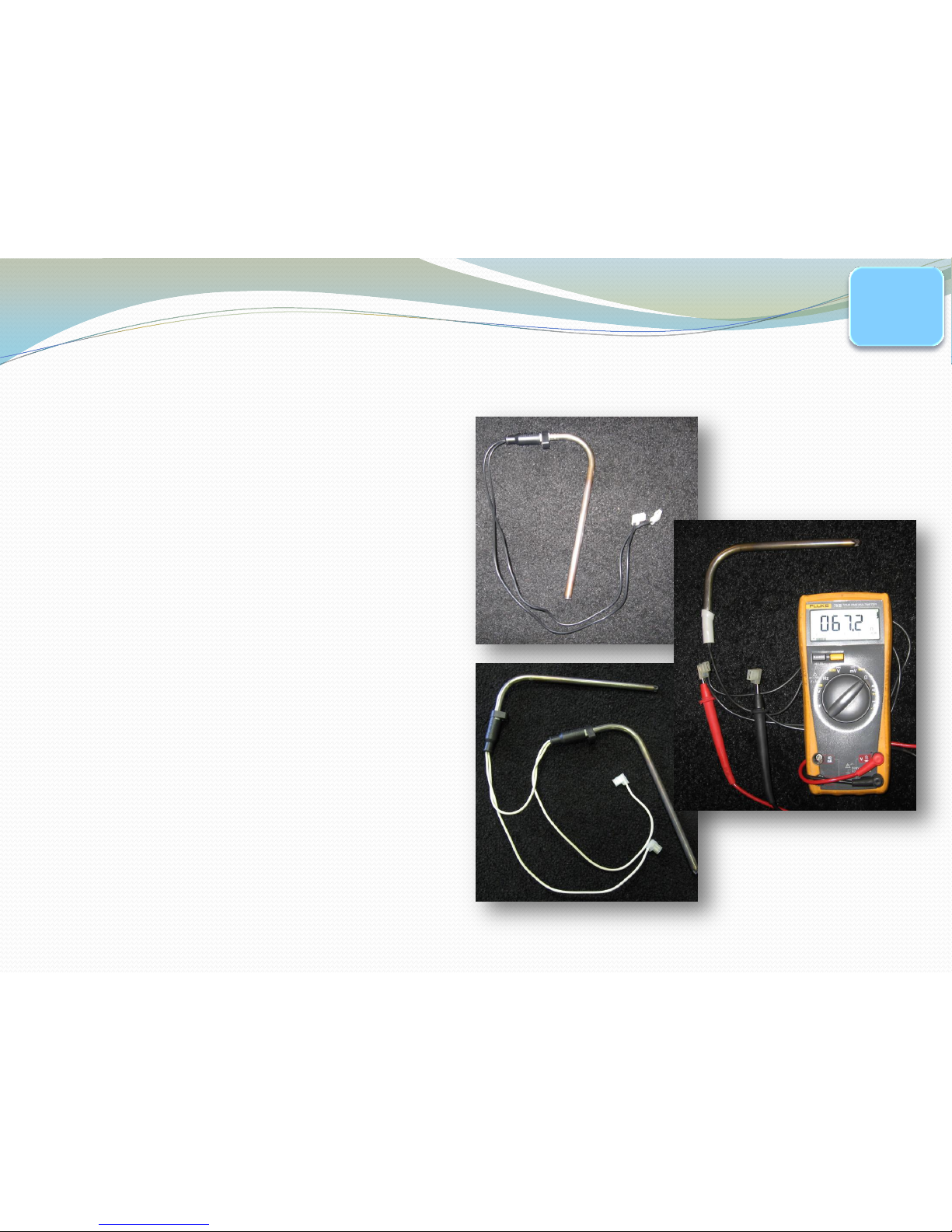
Heating Elements
The function of the heating element
is to provide the boiler with a
specific amount of BTU’s of Heat
AC Heating Element 6,8,10 cu ft.
Ohms – Approx. 44 +/- 10%
Amps – Approx. 2.7
Watts – 325
Series AC Heating Element for side
wise/side by side
Ohms – Approx. 34.3 +/- 10%
Amps – Approx. 3.5
Watts – 420
DC Heating element (Not shown) 6 cu ft.
Continuity – yes or no
Amps – Approx 18
Watts – Approx. 215
Note: Only use DC heating element
when driving to or from a location.
PG.
10/11
Page 12

To Perform a By-Pass Test of
the Cooling Unit
Disconnect the Thermister from Control Board
(with the thermister unplugged no temperature is
sensed, therefore, it will run continuously).
Place a glass of water in the refrigerator along with
a thermometer.
Plug unit into 115 VAC and allow to run “wide
open” for approximately 12 hours.
DO NOT DIRECT WIRE HEATING ELEMENT!
PG.
26
Page 13

Water/Thermometer
UNPLUG at P2 Terminal
To Perform a By-Pass Test of
the Cooling Unit
PG.
26
Page 14

After 12 hours Check
Liquid Temperature
•Industry Standards with
the thermister plugged IN…
•8 cubic foot and larger should
be 43°F or Less at 110°F
ambient temperature.
•6 cubic foot and smaller
should be 43°F or Less at 90°F
ambient temperature.
•After running “wide open”
for 12 hours with the
thermister unplugged…
•Should be approximately in
the lower 30’s under NORMAL
conditions.
PG.
26
Page 15

Refrigerator Specifications
A MINIMUM of 9.6 VDC at terminal block for controls
to operate properly.
Best from Battery, if not, from battery side of converter
or filtered side.
A MAXIMUM of 6 VAC ripple.
A Dedicated Fused Circuit – Nothing else tied into
circuit!
Must have 11” water column with 50% of all BTU
appliances on.
PG.
10
Page 16

Thermister
The function of the thermister
is to monitor the temperature
inside the refrigerator box
using resistance.
Symptom: Over Cooling or
Under Cooling.
Check Ohms Value of
thermister. In a glass of ice
water at approx. 34°F you
should see between 8500
and 9500 Ohms.
Note: NDA 1402 has different
value. At approx 34°F you
should see between 5000 to
6000 Ohms.
PG.
11
Page 17

UPPER CONTOL BOARD
The function of the Upper Control
Board is to send commands to the
Lower Control Board
Symptom: No LED lights or no operation
1
st
check for DC voltage at the 5/6 wire Harness
plugged into the P1 terminal on Lower Board.
Check between terminal 5 – red and terminal 4 +
orange wire. This is the DC voltage going to the upper
control board. Note: If no voltage, check
3 amp fuse
and then at the terminal block.
PG.
13
Page 18

5/6 Wire
Harness
The Function of the 5/6 Wire
Harness is to connect from the
lower board to the upper control
board .
Allows the upper board to
communicate with the Lower
Board.
Symptom: No LED lights, No
operation.
Check Continuity through each
wire to chassis ground.
Page 19

5/6 Wire Harness in P1
Connector
- Red to + Orange (UP)
- Red to + Green (GAS Down)
- Red to + Black (ELECT. Down)
Should see approximately:
9.6 VDC to 22 VDC
With no more than 1.5 volt
difference
•Turn on refrigerator.
•Check DC voltage coming from upper control board on P1 connector
•Check from - red to + Green and – red to + Black
Page 20

Lower Control Board
Minimum of 9.6 VDC to Maximum of 22 VDC
Minimum of 9.6 VDC for initial opening of Gas Valve
Note: Upper control board will stay lit at 4 VDC, but no
commands will be sent to lower control board
ALL TESTS ARE TO BE DONE WITH THE
REFRIGERATOR IN THE COOLING MODE
Unplug the thermister from the control board during
lower board testing to assure unit is calling for cooling.
PG.
17
Page 21

No AC Operation-works on LP?
OPERATION
INCOMING AC VOLTAGE
5 AMP FUSE
HEATING
ELEMENT
WIRING
LOWER
BOARD
Page 22

GAS COMPONENTS
Gas Solenoid
Gas Valve
Orifice
Igniter
Electrode
Burner
Thermocouple
Flue Baffle
Page 23

Gas Solenoid
The Function of the Gas Solenoid is to allow gas to
flow through the gas valve assembly.
Symptom:
Check Light or
NO LP (gas)
Needs at least
9.6 VDC to open
OHMS
49 +/- 10 %
PG.
11
Page 24

Manual Shut-Off Valve
The Gas Valve is responsible for allowing gas to the
burner chamber.
Symptom:
Check Light or
NO LP
Check manual
shutoff valve
(horizontal)
Manual
Shutoff
valve
PG.
19
Page 25

Orifice
The orifice provides a pre-determined amount of gas
to the burner. The orifice has a man-made ruby inset
that allows LP to mix with air in order to get
combustion.
Symptom: Check
Light or NO LP
Check orifice for Debris
Use ONLY alcohol based
solvent to clean. Soak in
solvent and allow to air dry
PG.
19
Page 26

IGNITER
The function of the re-igniter is to sense resistance through the flame
between the electrode and the burner. If there is no flame, the igniter
will spark to light the burner.
Symptom: Check
Light or No Flame.
No sparking sound or
there is continuous
sparking.
Verify voltage at
+ Yellow and
– black (ground)
Note: 2 versions, igniter on board and separate
PG.
11
Page 27

ELECTRODE
The electrode passes the spark to the burner to light
the burner.
Symptom:
Check Light or
No Spark
Check for cracks
or breaks in ceramic.
Proper location on Burner
Note: 3rd slot on burner and 3/16 above burner
3/16”
3 slots
PG.
12
Page 28

THERMOCOUPLE
The thermocouple’s function is to tell the control
board that a flame is present.
Symptom:
Check Light or
won’t stay lit.
Check wiring, leads
may be reversed.
Milli-volts test while in
flame, should produce 25-35 – milli-volts
PG.
20
Page 29

Flue Tube and Flue Baffle
The Flue Baffle helps slow the process of heat rise in
the flue tube. The Flue Tube is where heat is
transferred to the boiler.
Symptom:
Cools on AC
but not on LP.
Check that baffle
is present
Clean flue tube/baffle of Carbon Build up
Check water column (gas pressure)
PG.
20
Page 30

CLIMATE CONTROL/LAT SWITCH
Turning on the ambient temperature switch “ON” allows
the interior light to turn on so that it will cause the
refrigerator to cycle in cold temperatures. This will
prevent frozen foods from thawing. .5 amps
Turning the climate control switch on will turn on the
frame heater to prevent condensation around the frame.
.5 amps 24 ohms +/- 10%
Note: Not on
ALL models.
PG.
18
Page 31

Air Leak?
Air leaks can
cause a
situation like
this!
Over stocking
and not allowing
air flow on the
sides and back
of refrigerator
can also cause
excessive
frost.
Page 32

Troubleshooting a Check Light
DC Power Supply
Gas Supply
Grounds
Thermocouple
Burner
Reignitor
Electrode
Solenoid
Power Module
Control Panel
Installation of wire
harness
• DC – If DC voltage drops below 9.6VDC – AC ripple
on DC line (Dirty Voltage)
• Gas Supply - see components and discuss
* Grounds- a bad or loose ground can cause a Check
Light! A loose ground can create negative millivolts
☺ Discuss
• If a lower control board has recently been replaced
and the check light comes on at start up – review wiring
diagram of new control board and review installation
instructions – in some cases, a wiring harness needs to
be replaced and a ground wire needs to be removed.
(see next slide for example)
Page 33

P3 harness needs to be replaced
Ground wire needs to be removed
Page 34

New Universal Board
Page 35

Icemaker Operation
All icemakers require
120 volts AC to
operate.
Allow refrigerator to
Pre-Cool before
starting the icemaker.
Make sure Manual
Shut-Off valve is
“OPEN”.
Make sure that the
Bail Arm is in the
“DOWN” position.
PG.
27
Page 36

Mold Thermostat
This is a bi-metal switch. It
starts an ejection cycle by
closing at 12°F +/- 3°. The
reset temperature is
50°F +/- 5.
Symptom: Icemaker
is not making ice.
Test: Put a glass of
water or anti-freeze on the
shelf by the icemaker. Take
liquid temperature.
Page 37

Adjusting the Water Fill
Turn screw as
necessary toward the
“+” or the “-” side.
One FULL turn either
way will make an 18cc
change in the amount
of water.
DO NOT turn the
screw more than one
full turn at a time.
Page 38

Icemaker Water Valve
Valve is Solenoid Operated
Ohms Value is 200 to 500.
10-15 watts will energize the coil.
Note: When the solenoid is
energized, a voltage drop may occur.
Symptom: No water in mold. Have
already manually cycled icemaker.
Test: Check ohms on solenoid coil,
see if solenoid is energized when
icemaker is calling for water.
Page 39

How to Drain the Icemaker
Close the Shutoff Valve.
Place a pan under the
solenoid valve.
Remove the inlet fitting
from the water solenoid
valve. Drain water from
water line.
Remove the plastic nut
and water line from the
outlet side. Drain.
Cycle icemaker several
times while blowing
compressed air through
solenoid.
Note: Up to 40 PSIG.
Page 40

You are the reason we are here!
 Loading...