

Page 1
DIAGNOSTIC SERVICE MANUAL
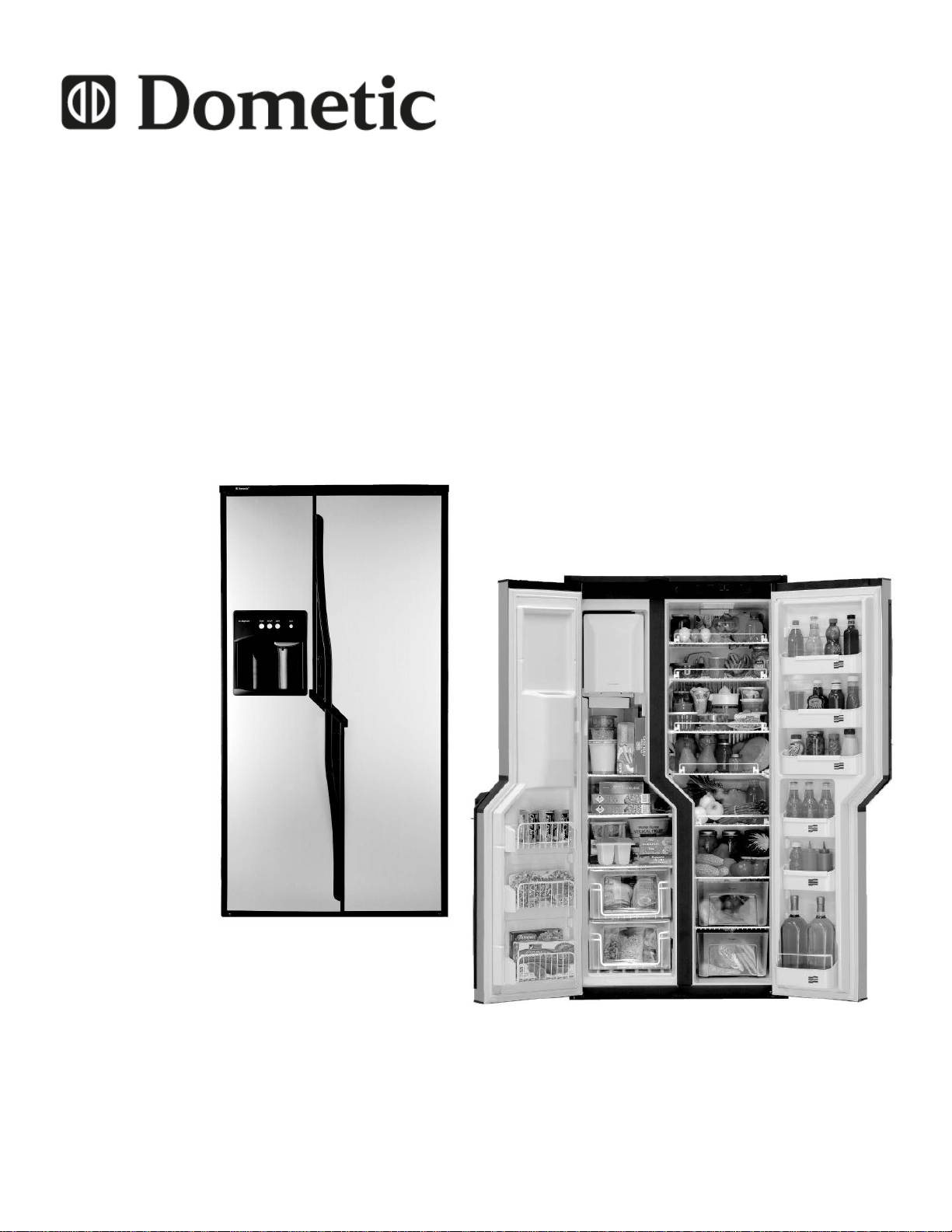
NDA1402 & NDE1402
WITH AUTO DEFROST
USA
Dometic, LLC.
2320 Industrial Parkway
Elkhart, IN. 46516
574-294-2511
CANADA
Dometic, LLC.
46 Zatonski Unit 3
Brantford, Ontario
CANADA N3T 5L8
519-720-9578
Form No. 3312260.000 06/08
©2008 Dometic, LLC.
LaGrange, IN. 46761 USA
Page 2

3
foreword
This service manual is the result of the dedication of Dometic, LLC technical staff and its engineers in giving service people the necessary
instruction for making accurate analyses of certain conditions. Provided is a diagnostic chart
leading a qualied mechanic into the service
manual pages to locate and solve symptoms
which may occur. Dometic, LLC has continued
its commitment in providing service people with
this, the most up-to-date information about servicing Dometic RV accessories.
Safety InStructIonS
This manual has safety information and instructions to help users eliminate or reduce the risk
of accidents and injuries.
recognIze Safety InformatIon
This is the safety-alert symbol. When you see this
symbol in this manual, be alert to the potential
for personal injury.
Follow recommended precautions and safe operating instructions.
underStand SIgnal WordS
A signal word, WarnIng OR cautIon is used
with the safety-alert symbol. They give the level
of risk for potential injury.
Indicates a potentially hazard-
ous situation which, if not avoided, could result
in death or serious injury.
Indicates a potentially hazard-
ous situation which, if not avoided may result in
minor or moderate injury.
When used without the safety
alert symbol indicates, a potentially hazardous
situation which, if not avoided may result in property damage.
Read and follow all safety information and instructions.
Page 3
32
contentS
Page no.
DIAGNOSTIC FLOW CHART..........................................................................6
SectIon 1
oVerVIeW/oPeratIon
Refrigerator Overview/Operation..........................................................................9
SectIon 2
ac Voltage
AC Voltage Requirements...................................................................................12
SectIon 3
ac comPonentS
3.1 Heating Element.........................................................................................12
3.2 Interface Module.........................................................................................13
3.3 AC Sensing.................................................................................................14
SectIon 4
dc Voltage
4.1 DC Voltage Requirements ....................................................................... ..14
4.2 Grounds......................................................................................................14
SectIon 5
dc comPonentS
5.1 Door Switches and lamps.........................................................................
5.2 Temperature Sensors................................................................................
5.3 Low Ambient Control.................................................................................
5.4 Frame Heater............................................................................................
5.5 Interior Fans..............................................................................................
5.6 Thermo Fuse..............................................................................................
5.7 Flame Sensing...........................................................................................
5.8 Ignition Control Module..............................................................................
5.9 Electrode....................................................................................................
5.10 High Voltage Cable....................................................................................
5.11 Solenoid (Gas)..........................................................................................
5.12 Front Display Panel...................................................................................
5.13 Lower Board.............................................................................................
5.14 Fuses........................................................................................................
14
15
15
15
16
16
16
17
17
17
18
18
21
21
SectIon 6
lP gaS
LP Gas Requirements.......................................................................................22
3
Page 4

5
contentS
Page no.
SectIon 7
lP gaS comPonentS
7.1 Manual Gas Shutoff Valve........................................................................22
7.2 Orice.......................................................................................................22
7.3 Burner.......................................................................................................23
7.4 Flue Bafe................................................................................................23
7.5 Flue Cap..................................................................................................23
7.6 Flue Tube.................................................................................................23
SectIon 8
coolIng unIt
8.1 Cooling Unit......................................................... ....................................23
8.2 Ventilation.................................................................................................25
8.3 Ventilator Fans.........................................................................................27
8.4 Leveling....................................................................................................27
8.5 Food Storage...........................................................................................27
8.6 Ambient Temperature...............................................................................27
SectIon 9
froSt
9.1 Door Seals...............................................................................................27
9.2 Interior Liner Seal to Frame.....................................................................28
9.3 Drain Tube...............................................................................................29
9.4 Wall Entrances.........................................................................................29
9.5 Auxiliary Defrost Fan................................................................................29
9.6 High Humidity...........................................................................................29
9.7 Door Position...........................................................................................29
SectIon 10
defroStIng
10.1 Real Time Clock.....................................................................................30
10.2 Automatic Defrosting..............................................................................30
10.3 Manual Defrosting..................................................................................31
10.4 Drying Function......................................................................................31
10.5 Freezer Defrost Heating Element..........................................................31
10.6 Fresh Food Defrost Heating Element....................................................32
10.7 Drain Tube/Tray Defrost Heating Element.............................................32
Page 5

54
contentS
Page no.
SectIon 11
trouBleSHootIng
11.1 Status Messages.....................................................................................33
11.2 Error Codes.............................................................................................34
11.3 Service Mode..........................................................................................36
SectIon 12
Ice maKer
12.1 Operation............................................. ..............................................38
12.2 Mold Heater...........................................................................................38
12.3 Ice Ejector..............................................................................................38
12.4 Mold Thermostat....................................................................................39
12.5 Shutoff Arm............................................................................................39
12.6 Mold Switches......................................................................................39
12.7 Timing Motor..........................................................................................39
12.8 Water Valve...........................................................................................39
12.9 Ice Maker Replacement........................................................................40
12.10 Water Fill Adjustment............................................................................40
12.11 Fill Tube................................................................................................40
12.12 Water Supply........................................................................................41
12.13 Wiring...................................................................................................42
SectIon 13
door dISPenSer
13.1 Operation................................................................................................46
13.2 Auger.......................................................................................................46
13.3 Solenoid.............................................................................................. .. . .. 47
13.4 Ice Shutter...............................................................................................47
13.5 Water Dispenser......................................................................................48
13.6 Door Mechanism and Display Panel........................................................48
SectIon 14
WIrIng
14.1 Internal Wiring........................................................................................48
14.2 External Wiring.......................................................................................48
14.3 Wiring Schematics..................................................................................48
SectIon 15
mIScellaneouS
15.1 Thermistors............................................................................................49
5
Page 6
7
This service manual will address the most common system problems associated with the NDA 1402 and NDE 1402 refrigerators supplied by Dometic, LLC. Our intent is to provide you with a guideline of checks to make, should you encounter
one of the following symptoms.
SYMPTOM
1. No operation - no panel lights
2. No operation - has panel lights
3. No AC operation - operates on gas
mode
CAUSE
Operation
DC Volts
Fuses
Wiring
Front Display Panel
Lower Circuit Board
Operation
DC Volts
Temperature Sensors
Wiring
Lower Circuit Board
Operation
AC Volts
Fuses
Heating Elements
Wiring
Lower Circuit Board
SECTION & PAGE
1, page 09
4, page 14
5, page 21
14, page 48
5, page 18
5, page 21
1, page 09
4, page 14
5, page 15
14, page 48
5, page 21
1, page 09
2, page 12
5, page 21
3, page 12
14, page 48
5, page 21
4. No Gas operation - operates on AC
mode
5. Insufcient cooling on all modes.
6. Insufcient cooling on AC - cools prop-
erly on gas mode.
Operation
LP Gas
Manual Gas Valve
Ignition Control Module
High Voltage Cable
Electrode
Solenoid (Gas)
Wiring
Lower Circuit Board
Ventilation
Ventilator Fans
Leveling
Ambient Temperature
Drain Tube
Wall Entrances
Temperature Sensors
Cooling Unit
AC Volts
Heating Elements
Lower Circuit Board
1, page 09
6, page 22
7, page 22
5, page 17
5, page 17
5, page 17
5, page 18
14, page 48
5, page 21
8, page 25
8, page 27
8, page 27
8, page 27
9, page 29
9, page 29
5, page 15
8, page 23
2, page 12
3, page 12
5, page 21
Page 7

76
This service manual will address the most common system problems associated with the NDA 1402 and NDE 1402 refrigerators supplied by Dometic, LLC. Our intent is to provide you with a guideline of checks to make, should you encounter
one of the following symptoms.
SYMPTOM
7. Insufcient cooling on Gas - cools
properly on AC mode.
8. Water on frame
9. Rapid formation of frost
CAUSE
LP Gas
Orice
Flue Bafe
Flue Tube
Burner
Lower Circuit Board
Interior Liner Seal to Frame
Wall Entrances
High Humidity
Frame Heater
Food Storage
Interior Liner Seal to Frame
High Humidity
Door Seals
Drain Tube
Wall Entrances
Auxiliary Defrost Fan
SECTION & PAGE
6, page 22
7, page 22
7, page 23
7, page 23
7, page 23
5, page 21
9, page 28
9, page 29
9, page 29
5, page 15
8, page 27
9, page 28
9, page 29
9, page 27
9, page 29
9, page 29
9, page 29
10. Unit is not defrosting
11. Frost around drain tube
12. General Frost (freezer)
13. General Frost (fresh food)
Real Time Clock
DC Volts
Temperature Sensors
Freezer Defrost Heating Element
Drain Tube/Tray Heating Element
Fresh Food Heating Element
Drain Tube orice is too Small
Drain Tube/Tray Heating Element
Wall Entrances
Door Seals
Interior Liner Seal to Frame
Wall Entrances
Drain Hose
Freezer Defrost Heating Element
Drain Tube/Tray Heating Element
Door Seals
Interior Liner Seal to Frame
Wall Entrances
Drain Hose
Fresh Food Heating Element
Drain Tube/Tray Heating Element
10, page 30
4, page 14
5, page 15
10, page 31
10, page 32
10, page 32
9, page 29
10, page 32
9, page 29
9, page 27
9, page 28
9, page 29
9, page 29
10, page 31
10, page 32
9, page 27
9, page 28
9, page 29
9, page 29
10, page 32
10, page 32
7
Page 8
9
This service manual will address the most common system problems associated with the NDA 1402 and NDE 1402 refrigerators supplied by Dometic, LLC. Our intent is to provide you with a guideline of checks to make, should you encounter
one of the following symptoms.
SYMPTOM
14. Ice maker fails to start
15. Not making enough ice
16. Ejector blades frozen into ice
17. Ice around ice maker
18. No ice or water at the dispenser
CAUSE
Operation
Mold Thermostat
Shutoff Arm
Water Valve
Interface Module
Operation
Mold thermostat
Water Fill Adjustment
Water Supply
Water Valve
Water Fill Adjustment
Water Supply
Fill Tube
Operation
Lock Out Feature
Freezer Door is Open
Door Mechanism and Display
Panel
Interface Module
SECTION & PAGE
12, page 38
12, page 39
12, page 39
12, page 39
3, page 13
12, page 38
12, page 39
12, page 40
12, page 41
12, page 39
12, page 40
12, page 41
12, page 40
13, page 46
13, page 46
13, page 46
13, page 48
3, page 13
19. No ice at the dispenser
20. No “cubed” ice at the dispenser
21. Water/Condensation at the dispenser
Operation
Lock Out Feature
Freezer Door is Open
Door Mechanism and Display
Panel
Auger
Interface Module
Operation
Door Mechanism and Display
Panel
Solenoid
Interface Module
Water Fill Adjustment
Ice Shutter
High Humidity
13, page 46
13, page 46
13, page 46
13, page 48
13, page 46
3, page 13
13, page 46
13, page 48
13, page 47
3, page 13
12, page 40
13, page 47
9, page 29
Page 9
98
SectIon 1
uSIng tHe control featureS
refrIgerator oVerVIeW
aBSorPtIon coolIng SyStem
In an absorption refrigerator system, ammonia is liqueed
in the nned condenser coil at the top rear of the refrig-
erator. The liquid ammonia then ows into the evaporator
(inside the freezer section) and is exposed to a circulat-
ing ow of hydrogen gas, which causes the ammonia to
evaporate, creating a cold condition in the freezer. When
starting this refrigerator for the very rst time, the cooling
cycle may require up to four hours of running time before the cooling unit is fully operational. The tubing in the
evaporator section is specically sloped to provide a con-
tinuous movement of liquid ammonia, owing downward
by gravity through this section.
ImPortance of leVelIng
Leveling is one of the requirements for proper operation
with absorption refrigerators. To ensure proper leveling
the vehicle needs to be leveled so it is comfortable to live
in (no noticeable sloping of oor or walls). Any time the
vehicle is parked for several hours with the refrigerator
operating, the vehicle should be leveled to prevent this
loss of cooling. If the refrigerator is operated when it is
not level and the vehicle is not moving, liquid ammonia
will accumulate in sections of the evaporator tubing. This
will slow the circulation of hydrogen and ammonia gas, or
in severe cases, completely block it, resulting in a loss of
cooling. When the vehicle is moving, the leveling is not
critical, as the rolling and pitching movement of the vehicle will pass to either side of level, keeping the liquid
ammonia from accumulating in the evaporator tubing.
automatIc defroStIng control SyStem
This refrigerator is equipped with an automatic defrosting control system. The defrost system will automatically carry out a defrost of the frozen food and fresh food
compartments once every 24 hours. To be able to control the performance of the defrost intervals the system is
equipped with a built in real time clock. The clock has to
be set to local time at the very rst start up of the refrigerator or when the 12 volt DC supply has been disconnected
for a long period of time. A message on the LED display
panel will alert when the clock needs to be set. It is also
recommended to reset the clock when entering different
time zones.
modeS of coolIng
nda1402: This refrigerator is equipped with an automatic
energy selector system which automatically selects the
most suitable energy source that is available, either 120
volt AC or LP gas operation. The system can be set by the
user to be fully automatic, or to operate on LP gas only.
nea1402: All-electric operation.
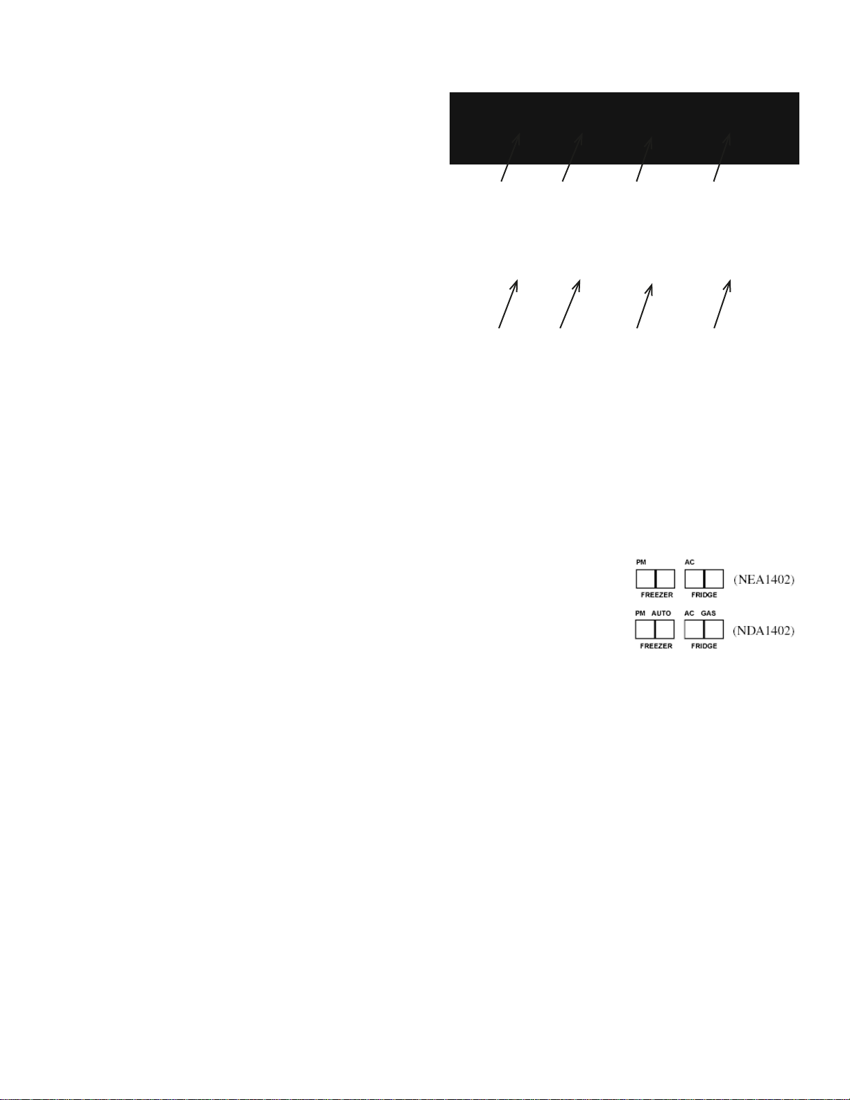
NEA1402
1
1
1. ON/OFF button.
Press this button to turn the refrigerator on and off.
2. STORE button. (NEA1402)
AUTO/STORE button. (NDA1402)
Combined energy mode selection and store button.
3. LED display panel.
4. SET button.
Combined temperature range and real time clock ad-
justment.
2
2
3
3
4
NDA1402
4
led dISPlay Panel
The LED panel displays
temperatures in the refrigerator, current modes of
operation and other useful
status messages.
The displayed temperature values reect the most probable temperature of the food in the two compartments. A
delay function prevents rapid changes due to door openings etc.
Panel Indications:
•
The most probable temperature of food in the frozen food compartment.
The most probable temperature of food in the •
fresh food compartment.
AUTO mode indication (NDA1402)•
AC operation indication.•
GAS operation indication (NDA1402)•
Thermostat setting indication (temporary during •
setting).
Real time clock/ PM indication (temporary during •
setting).
Various status and error messages.•
Store functIon
When setting the real time clock as well as the thermostat,
the desired setting is stored automatically after 5 sec. of
inactivity or by pressing the STORE button.
9
Page 10
11
oPeratIon
Before starting the refrigerator, check that all the manual
gas valves are in the “ON” position. DO NOT forget the
manual shutoff valve on the rear of the refrigerator. The
NDA1402 model refrigerator is equipped with a control
system which can be set to automatically select either 120
volt AC or LP gas operation (AUTO mode), or if desired
LP gas only (GAS mode). The NDE1402 model refrigerator is an all electric 120 volt AC operation.
most lP gas appliances used in recreational
vehicles are vented to the outside of the vehicle. When parked close to a gasoline pump
or traveling through tunnels, it is possible
that the gasoline fumes could enter this type
of appliance and ignite from the burner ame,
cauSIng a fIre or an eXPloSIon.
for your Safety, when refueling or traveling through tunnels, shut off all lP gas appliances which are vented to the outside.
deScrIPtIon of oPeratIng modeS
auto mode
When operating in the AUTO mode, the AUTO mode
indicator dot is lit. The control system will automatically
select between AC and GAS operation with AC having
priority over GAS. (An indicator dot will be lit to inform of
the energy source selected). If the control system is operating with AC energy and it then becomes unavailable,
the system will automatically switch to GAS. As soon as
AC becomes available again the control will switch back
to AC operation.
gas operation (120 volts AC is not available). The control system will activate the ignition system and will make
three attempts to light the burner for a period of approximately 45 seconds with two minutes rest (purge) interval.
If unsuccessful, “ch LP” will be displayed. To restart an
ignition attempt with “ch LP” in the display turn the unit off,
wait a few seconds and turn back on. The control system
will attempt a new ignition sequence. If 120 volts AC becomes available while “ch LP” is displayed, the refrigerator will operate on AC but the “ch LP” will not turn off until
the main power ON/OFF button is pressed to the “OFF”
then “ON” position.
automatIc energy Selector control
SyStem
The NDA1402 model is equipped with an automatic energy selector control system. The user turns the refrigerator
on and selects the desired temperature and then, the control system selects the most suitable energy source available (either 120 volt AC or LP gas operation). The system
can be set by the user to be fully automatic (AUTO mode
ON) or to operate on LP gas only (AUTO mode OFF).
The NDE1402 model is an all electric operation.
Press AUTO/STORE button to select AUTO mode operation or to chose LP-gas mode of operation only.
modeS of oPeratIon (auto) & (gaS)
When the refrigerator is in the AUTO mode, it automati-
cally uses the most efcient energy source that is avail-
able for operation. Should a more efcient energy source
become available during operation, the refrigerator will
change from the current energy source to the more ef-
cient energy source as follows:
gaS mode
When operating in the GAS mode, the AUTO indication
dot will be off and the GAS indication dot is lit. This mode
provides LP gas operation only. The control system will
activate the ignition system and will make three attempts
to light the burner for a period of approximately 45 seconds with two minutes rest (purge) interval after each trial.
If unsuccessful, “ch LP” will be displayed. To restart GAS
Operation, press the main power ON/OFF button to the
“OFF” and then “ON” position. The control system will attempt a new ignition sequence. If the refrigerator has not
been used for a long time or the LP tanks have just been
relled, air may be trapped in the supply lines. To purge
the air from the lines may require resetting the main power
ON/OFF button three or four times. If repeated attempts
fail to start the LP gas operation, check to make sure that
the LP gas supply tanks are not empty and all manual
shutoff valves in the lines are turned on.
to Shut off the refrigerator
The refrigerator may be shut off while in any mode of
operation by pressing the main power ON/OFF button
to the “OFF” position. This shuts off all DC power to the
control system including the interior light.
•
AC operation (if 120 volt AC is available). AC operation is only possible in AUTO mode.
GAS operation (if 120 volt AC is not available).•
GAS mode (manual LP gas operation)
When the AUTO mode is turned off, the refrigerator
uses gas as an energy source - even if AC is available.
Page 11
1110
Start uP
tHermoStat SettIng
NDE1402:
Turn on the refrigerator by pressing the ON/OFF button.
NDA1402:
fIre Hazard. If the refrigerator has not
been used for some time, and before lighting the gas burner. check that the gas path
between the burner jet and the burner tube
has not been obstructed. failure to heed
this warning could cause a re resulting in
death, severe personal injury and property
damage.
•
Before turning on the refrigerator, verify that all the
manual gas valves, including the manual shut off
valve, are in the “ON” position.
•
Turn on the refrigerator by pressing the ON/OFF button.
The freezer and the fresh food compartment temperatures are controlled separately and independently of each
other, based on the actual air temperature in each compartment.
•
The freezer setting is pre-set (can not be changed) to
be approx. 0°F (-18°C) when running on AC. If running on GAS the pre-set temperature is approx. 7°F
(-14°C).
•
The fresh food compartment can be set in 5 different
positions (1-5) where 5 is the coldest setting which
gives a fresh food temperature of approx. 33°F (0°C).
Setting 3 gives a temperature of approx. 37°F (3°C).
NEA1402
NDA1402
real tIme clocK
NEA1402
PM INDICATION
PM INDICATION
If the real time clock has to be set, the LED panel will
show ashing horizontal bars ” -- -- “.
To enter “TIME MODE”, keep the SET button pressed
•
until gures ash on the LED panel.
(Hours are to the left and minutes to the right.)•
Press the SET button to adjust to local time. AM/PM •
should also be set here.
Store each setting by pressing the AUTO button (NEA •
1402) - AUTO/STORE button (NDA 1402) or use the
automatic store function (wait 5 sec.).
HOURS
HOURS
MINUTES
NDA1402
MINUTES
note: It is important to check the clock setting every
month and to reset when entering different time zones.
This is to allow proper defrosting daily at 1:00 am.
Press the SET button to set the thermostat. Thermo-•
stat range is 1 to 5, where 5 represent’s the coldest
compartment temperature.
Press the STORE button to store or use the automatic
•
store function (wait 5 sec.).
manual defroSt
NDE1402
NDA1402
The refrigerator can be set to defrost at any time. Usually a defrost cycle takes about 1 hour but will depend on
the amount of frost and could therefore vary from time to
time.
•
Switch off the refrigerator with the ON/OFF button.
Press and hold the AUTO button (NEA 1402) - AUTO/ •
STORE button (NDA 1402). Then, press the ON/OFF
button. “dE Fr” is displayed.
11
Page 12
13
The drip tray catches small
spills. The tray is removable
and dishwasher safe.
It is not a drain;
pour water directly into this
area.
DO NOT
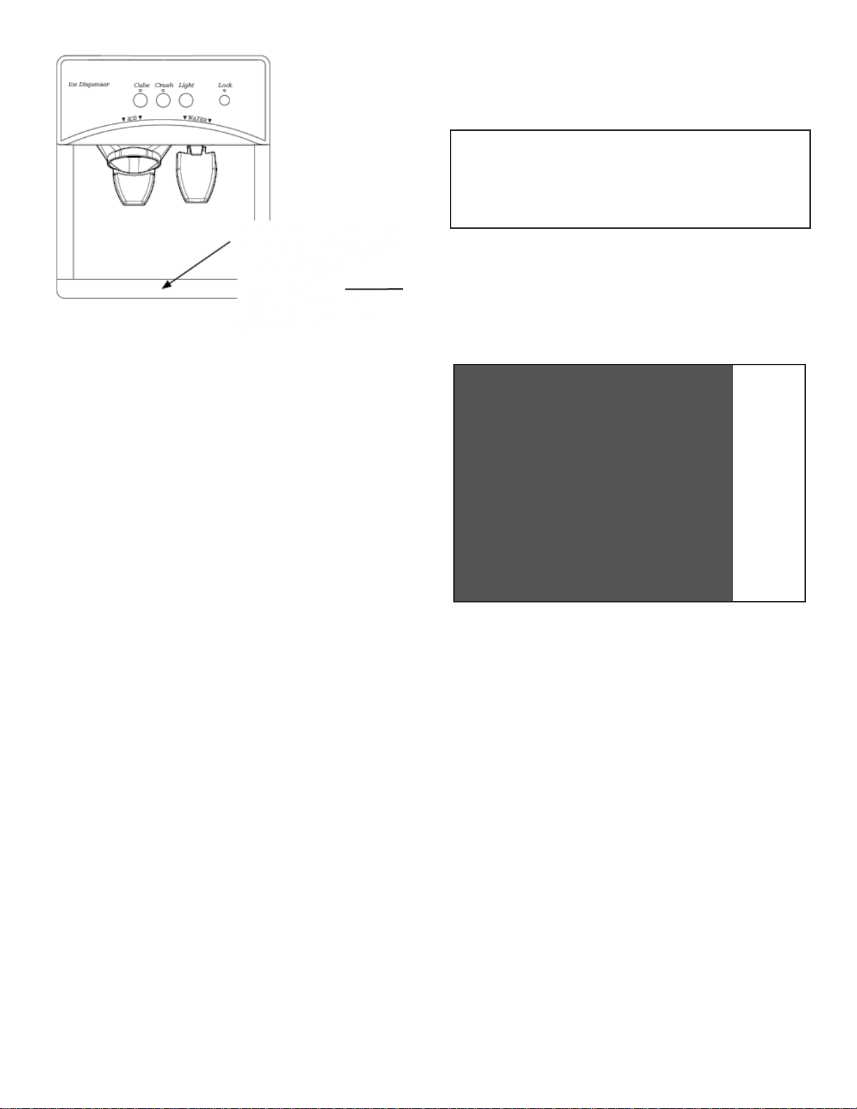
Ice dISPenSer (oPtIonal)
For a refrigerator to provide ice through the door, the ice
maker rst dumps the ice it produces into a large bin. To
request ice at the door, select Cube or Crush and then
press the lever. This will activate a switch which turns on
a motor that rotates the auger. When the auger rotates,
it pushes ice out of the bin, through a chute right into the
glass. To stop dispensing, pull the glass away from dispensing arm before the glass is full. Allow the ice chute to
clear before removing the glass.
SectIon 2
ac Voltage
ac Voltage reQuIrementS
this is an energized circuit. Shock can occur
if not tested properly. testing is to be done
by a qualied service technician.
The refrigerator is a 120 volt AC, 60 Hz appliance. The
proper operating range is 108 to 132 volts. If the voltage
drops below 108 volts, cooling efciency will decrease as
the voltages decreases. Check the AC volts at the receptacle where the refrigerator is attached. If the voltage is
outside of the proper operating range, correct the power
source problem.
120 Volt ac
receptacles
Might have separate
power cords if unit
has an Ice Maker
Water dISPenSer (oPtIonal)
The water dispenser works much like the ice dispenser.
To request water at the door, simply press the lever. This
will activate a switch which turns on an electric water valve
at the back of the refrigerator. Water will ow through a
separate tube right into the glass.
note: The NDA/NDE1402 models use “Non-chilled”
water at the door dispenser.
locK out feature
The ice dispensing system can be locked out to prevent
unwanted use.
lock out•
To lock out, press the “Lock” pad for (3-5) seconds
until the RED light above the Padlock comes on.
unlock•
To unlock, press the “Lock” pad for (3-5) seconds until the RED light above the Padlock goes out.
dISPenSer lIgHt
The light can be turned on and off by pressing the “Light”
touch pad. The light will illuminate the dispenser area.
The light will also turn on automatically when ice or water
is dispensed.
automatIc PoWer SuPPly SWItcH off
For safety reasons, when opening the freezer door, the
ice/water dispenser and ice maker system will automatically shut off. Closing the freezer door automatically resumes operation of ice/water dispensing and ice maker
operation.
The refrigerator is equipped with a three-prong (grounding) plug for your protection against shock hazards and
should be plugged directly into a properly grounded three
prong receptacle.
ing prong from this plug! The free length of the cord
is 3 feet. It is recommended that the receptacle is located to the right side of the refrigerator (viewed from the
rear). The receptacle should be 3” (from the bottom of the
plastic receptacle) above the refrigerator mounting oor.
This allows easy access through the vent door. The cord
should be routed to avoid direct contact with components
that could damage the cord insulation. The refrigerator
will not switch to another mode of operation until all AC
power is lost.
do not cut or remove the ground-
SectIon 3
ac comPonentS
3.1 Heating element
The heating elements are designed to deliver a predetermined amount of heat to the cooling unit. To check a
heating element, remove the heater leads from the printed circuit board and measure for proper resistance across
the two leads with a properly calibrated Ohm meter. This
check is to be done with the heating element at room temperature. You should obtain the following readings ± 10%.
Page 13
1312
model Watts ohms amps
NDA 1402 420 34.3 3.5
NDE 1402 420 34.3 3.5
The NDA/NDE1402 models use two AC heaters wired in
series. The resistance should be 34.3 Ohms +/- 10%.
note: never over or under size the ac heater.
3.2 Interface module
The interface module is used for two reasons:
The tabs on the module are from left to right:
•
(4) Interconnected tabs that serve as interconnection points of four neutral wires (white).
(2) Interconnected tabs that serve as intercon-•
nection points of the “auger wire” from the door
and the wire to the auger motor (yellow).
(2) Interconnected tabs that serve as intercon-•
nection points for the “cube wire” from the door
and the wire to the solenoid (red).
(2) Interconnected tabs that supply switched 120
•
volt AC to the door and to the ice maker (black).
(1) Tab for incoming 120 volt AC to the interface •
module (black).
To shut off the 120 volt AC supply to the door dispens-
•
er and ice maker when the freezer door is opened (for
safety Reasons).
To shut off the 120 volt AC supply to the door dispens-•
er and ice maker when the refrigerator is switched
“OFF” by means of the ON/OFF button on the upper
display panel.
The function of this additional module is very simple. It
has a (5 amp) fuse for incoming 120 volt AC line voltage and a relay that switches the line voltage ON/OFF.
The relay is driven by a circuit that senses the voltage at
the node between the door switch and the interior lamp.
This relay is controlled by the wires in the P1 connector on the interface module. These wires are hooked on
the wires coming from the power module to the lamp and
door switch. The black wire is ground (-), the white wire is
12 volt DC (+) and the yellow wire is going to the connection point between the lamp and door switch. If the door
is opened, the yellow wire should be 12 volt DC (+) and
if the door is closed, the reading should be 0 volts DC. If
the lamp is lit or if 12 volt DC is absent, the relay will drop
out and 120 volt AC will not be supplied to the ice maker
or the door dispenser.
To troubleshoot the module:
Check that the wires are correctly connected to
•
the tabs.
When the door is shut, check that 120 volt AC is •
present on the tabs (J9) and (J10).
When the door is open, check that the voltage on •
these tabs (J9) and (J10) is 0 volts AC.
If 120 volts AC is not present on (J9) and (J10) •
when door is closed, check the fuse.
If the fuse is OK, check that the interior light in the •
freezer is working, (switched on/off when pressing/releasing the door button).
If the interior light is OK, check if the relay is •
“clicking” when the door is opened/closed (you
will need an assistant to operate the door while
you are touching the relay with a nger to sense
if it is “clicking”.
If the relay is not clicking though the interior light •
is correctly switched ON/OFF, measure the voltages on the pins in the P1 connector. The voltages should be as described previous, in this
section.
If the voltages in the P1 connector are OK and •
still the relay is not clicking when opening/closing
the door, the module is faulty; the transistor that
drives the relay is probably damaged.
this is an energized circuit. Shock can occur
if not tested properly. testing is to be done
by a qualied service technician.
13
Page 14

15
3.3 ac Sensing
The incoming 120 volt AC supply is constantly checked
for availability by means of an opto-coupler. There is a
delay of approximately 15 seconds before a change is
recognized to avoid spurious switching. When AC is not
available in AC only refrigerators, the message “no AC” is
shown on the front display panel.
SectIon 4
dc Voltage
4.1 dc Voltage reQuIrementS
Clean Direct Current (DC) power is mandatory for hightech circuits to operate as designed. A battery will provide
straight line DC power. The converter and alternator produce DC power by a series of diodes that rectify alternating current to DC. The Dometic control system will only
tolerate up to 6 volts AC on the DC line (Also known as
AC ripple). AC ripple can be measured by a digital voltmeter set on the AC scale and measured at the main DC
terminal block connections at the back of the refrigerator. 6 volts AC or less is acceptable. If AC volts exceed
6 on the incoming DC line, the power source should be
cleaned. AC voltage in excess of 6 volts will affect the
processor and create erratic operation. When testing for
AC ripple on the DC line put a load on the converter. The
operational range of the unit is a minimum of 8.5 volts
DC to a maximum of 18 volts DC (However 10.5 volts DC
minimum is required to activate the defrost system). The
unit will automatically shut down at 18 volts DC or greater,
and come back on when voltage has decreased to the
proper operating range. The refrigerator requires at least
8.5 volts DC for proper cooling operation. The refrigerator
must be connected to the battery circuit with two wires of
adequate capacity to avoid voltage drop. Proper polarity is crucial for refrigerator operation. No other electrical
equipment or lighting should be connected to the refrigerator circuit. Just because you can read volts, does not
mean you have the amps to operate the control system.
If relays buzz, lights go dim or out during operation, this
could indicate there is a loose connection somewhere. As
a last test, use a battery and run wires directly to the DC
terminal block. If the unit works OK on direct DC voltage
the problem is in the coach, not the refrigerator control
system.
note: The defrosting cycle will not start if the voltage is
below 10.5 volts DC. It is important that the wires to the 12
volt DC terminal block are of proper wire size.
•
Check the wire gauge to ensure that it is in accordance with recommended dimensions.
length (ft) min. size (aWg)
< 33 12
33-66 10
> 66 8
4.2 groundS
The operation of the Dometic refrigerator is also dependent on good, clean ground connections. Loose or corroded ground terminals create an unknown resistance factor
that can affect the voltage detected by the Power Module.
A loose negative DC wire will create a negative millivolt
signal that the control board will pick up and create erratic
operation. Check the integrity of the grounds from the refrigerator all the way to the power source/battery. Clean or
tighten any suspicious looking connections.
Main Terminal Block
note: The DC terminal block located on the back of the
refrigerator should be cleaned and tightened at all four
wires.
SectIon 5
dc comPonentS
5.1 door Switches and lamps
Both compartments have interior lights controlled by door
switches. Both lamps are of a halogen type. The lamp
in the freezer compartment is rated at 5 watts, while the
lamp in the fresh food compartment is a 10 watt lamp.
Lamps and switches are directly connected to the power
module. The wires are foamed in and end up in the 10
pin Molex MiniFit P4 connector on the main circuit board.
The lamps are directly controlled from the switches and
the interconnections are on the main board. The processor on the power module cannot control the lamps but
senses if the switches are closed or not, to decide if doors
are open or closed (Used in the diagnostic mode). The
door switches are open when the switch arm is depressed
(interior light should be off). When the door is open the
switch is closed (interior light should be on). Check that
the switch assembly is properly aligned and that it is not
broken. Check the switch assembly for continuity. To do a
continuity check, rst be sure all power is disconnected or
“OFF” to the refrigerator. Second, remove all wires from
the switch assembly, then check the switch. When the
switch is depressed, there should be no continuity. When
the switch is NOT depressed, there should be continuity.
If any of these checks are incorrect, replace the switch.
After the check, be sure the switch assembly is wired
properly per the wiring diagram.
Page 15
1514
5.2 temperature Sensors
The NDA/NDE 1402 has two sets of thermistors. One
for the freezer and the other for fresh food compartment.
The display range is from - 9° F to 41° F in the freezer
and from - 9° F to 59° F in the fresh food side. For temperatures below and above these ranges, the display will
show “Lo” and “hi” respectively.
During normal operation, the temperatures in degrees
Fahrenheit in the compartments are shown on the display,
freezer to the left and fresh food to the right. However,
the shown temperatures are not the ones actually measured. Instead they are calculated as the most probable
temperatures of the food that is stored in the respective
compartment. Therefore these temperatures should not
be compared with temperatures measured with ordinary
thermometers placed inside the compartments. When the
power is switched “OFF” and then “ON” again, the temperature lters will forget historical values and the calculation restarts from the beginning. In this case the shown
values will be about 2° F above the real air temperatures
at the sensors.
Each thermistor harness consists of two thermistor sensors. One each for “air” and the other for “surface” for the
defrosting process.
Disconnect the thermistor harness from the P2, 4-pin terminal (freezer) or P3, 4-pin terminal (fresh food) on the
lower circuit board. Place the sensing tip in a glass of ice
water (more ice than water), approximately 33° F to 35°
F. Wait 8 to 10 minutes. You should get a reading of approximately 5,500 Ohms. Always test from the wire side of
the 4-pin connector with the meter leads as not to create a
connection problem at either the P2 or P3 connector.
note: A disconnected or faulty thermistor will result in an
error code displayed on the front display panel. See section 11 for trouble shooting error codes.
Fresh food air thermistor:
Remove the P3 connector from the lower control
board. Check the resistance between pins 1 and 2 on
the P3 connector.
Fresh food surface thermistor:
Remove the P3 connector from the lower control
board. Check the resistance between pins 3 and 4 on
the P3 connector.
Freezer air thermistor:
Remove the P2 connector from the lower control
board. Check the resistance between pins 1 and 2 on
the P2 connector.
Freezer surface thermistor:
Remove the P2 connector from the lower control
board. Check the resistance between pins 3 and 4 on
the P2 connector.
note: See page 49 for thermistor values at varying tem-
peratures.
5.3 low ambient control
The automatic Low Ambient Control ensures trouble free
operation in low ambient temperatures (e.g. Below 50° F).
In colder weather, the temperature inside the fresh food
compartment tends to hold the temperature inside for a
very much longer period of time, with very long periods
in between ON/OFF cycling of the heat source; this is OK
for any food product inside the fresh food compartment,
but is not OK for the freezer compartment. The NDA/
NDE1402 have active thermostatic control of both compartments (however, you can only set the temperature
level for the fresh food thermostat). If the temperature in
the freezer is not low enough, the cooling is switched on.
If the fresh food compartment then becomes too cold, the
defrosting element will be switched on to keep it at the
correct temperature.
Air sensor
4-pin connector
Surface
sensor
5.4 frame Heater
The frame heater is located behind the metal frame between the doors. The heater helps to reduce sweating on
the metal frame during periods of high humidity. The heater is on all the time except during the defrosting phases
to reduce maximum current draw from the DC supply. To
test the heater, remove the white wire from terminal (J4)
and measure the resistance between the wire removed
and chassis ground. You should have a resistance reading of 24 Ohms +/- 10%.
note: Some units may have a Light blue wire on J4.
15
Page 16

17
5.5 Interior fans
5.6 thermo fuse
Both compartments have fans to help distribute the temperature evenly throughout the unit. These fans are DC
operated and are connected directly to the lower power
module. Both fans run continuous when the ON/OFF
switch is in the “ON” position and the doors are closed.
The fan in the fresh food side will run when the door is
open, however the freezer side is stopped during opening
of the door. The fans can be tested by applying DC power
directly to the power leads.
The NDA/NDE 1402 cooling unit has a thermo fuse located on the boiler. The function of the thermo fuse is to
shut down the control system in the event of a cooling
unit problem. On certain units the fuse can be reset by
pushing the button in the center. The thermo fuse is a non
replaceable component of the cooling unit. When the fuse
pops, it is normally an indication the cooling unit has a
problem and the cooling unit will have to be replaced. To
test the thermo fuse, check for continuity. Lack of continuity would indicate a faulty thermo fuse.
Thermo fuse
on boiler
Connection Block
Fresh food fan:
Remove the P4 connector from the lower control
board. Apply 12 volts DC directly to pin 10 red wire
(+) and pin 5 black wire (-). The fan should run. This
test can also be performed at the terminal connection
block just below the fan assembly. If the fan fails to
run, it will need to be replaced.
Freezer fan:
Remove the P5 connector from the lower control
board. Apply 12 Volts DC directly to pin 4 red wire (+)
and pin 1 black wire (-). The fan should run. This test
can also be performed at the inter-connection box
along the back wall behind the ice maker assembly. If
the fan fails to run, it will need to be replaced.
In order to prevent the circulation of warm air throughout
the compartments and to reduce the current draw on the
DC supply, both fans will be stopped after approximately
10 seconds if a source to heat the cooling unit is not available (e.g. No AC detection and failure to lite on gas “ch
LP”) in the front display panel.
note: A disconnected or faulty fan assembly will result
in an error code displayed on the front display panel. See
section 11 for trouble shooting error codes.
5.7 flame Sensing
The ame is detected by a method often called “ame
rectication sensing”. A gas ame is slightly conductive
and by applying a voltage to the spark electrode, a small
current will ow through the ame to chassis ground.
However, the ame conductivity depends on the polarity
of the applied voltage. A positive voltage on the electrode
will result in a higher current than a negative voltage. This
“rectication property” of the ame is used to distinguish
it from leakage currents that could be caused by dirt or
moisture. To detect if a ame is present, a high frequency
AC voltage is applied between the burner and the electrode. This results in a net current in the forward direc-
tion if the ame is present, but no current if the ame is
not present. The rectication property then causes that
the electrode will have a slightly negative DC voltage that
is detected by the ignition control module. The AC voltage and the resulting negative voltage are not possible
to measure with normal methods, as the impedance is
too high.
Page 17

1716
this is an energized circuit. Shock can occur
if not tested properly. testing is to be done
by a qualied service technician.
5.8 Ignition control module
The ignition control module supplies continuous DC voltage to the gas valve during gas operation. On gas operation the ignition control module senses the resistance
through the ame between the electrode and burner.
When there is no ame at the burner, the resistance is
high and the ignition control module begins sparking to
light the burner. As soon as the ame is lit, the resistance
between the electrode and burner drops and the ignition
control module stops sparking. The resistance is monitored by the ignition control module and, if for any reason
the ame goes out, the ignition control module begins
sparking until the burner is lit. The resistance between
the electrode and burner drops and the ignition module
stops sparking. This insures that the ame will always be
lit when desired. First verify proper voltage at the Yellow
(+) and White (–) terminals on the 4-pin connector of the
ignition control module. This reading should be 8.5 volts
DC or greater. Next, remove the high voltage cable from
the ignition control module. The ignition control module
should produce a sparking sound, during trial-for-ignition.
If not, replace the ignition control module. While operation
in the gas mode, the ignition control module is constantly
monitoring the presence of ame. If the ame is blown out,
the ignition control module will immediately start sparking.
When the ignition control module senses the loss of ame
(High resistance thru the electrode) the 45 seconds trial
for ignition period is started.
The ignition control module has an additional ground strip
wire underneath the left mounting tag. This wire must be
in good contact with the metal frame of the burner assembly before the system is energized. Otherwise both
the ignition control module and the power module may be
damaged. At every gas operation request from the power
module, the ignition control module performs an integrity
test of the gas burning system. This test will detect if the
system is operable or not. A message code will result in
a lock out mode. “ch LP” will be displayed on the front
display panel.
note: The message “ch LP”, for safety reasons will re-
main until the power is switched “OFF” and then “ON”.
5.9 electrode
Do a visual check for cracks, breaks or moisture on the
ceramic insulator. A hair line crack can be hard to see at
the electrode. The spark gap must be set at three sixteenths (3/16”) of an inch between the tip of the electrode
and the slots in the burner. When adjusting, always loosen
the screw and move into place. Never try to move without
loosening the screw. On certain units the electrode and
high voltage cable are integrated in to one component. To
acquire the proper part always provide the product number of the model refrigerator you are working on.
High voltage cable
to electrode
Leads from the
main control board
Power leads
to gas valve
5.10 High Voltage cable
If sparking starts during trial-for-ignition, the cable is good.
If there is no sparking during trial-for-ignition, disconnect
DC power at the refrigerator terminal block or switch the
unit off. Disconnect the high voltage cable from the electrode. Reconnect DC power. If there is a sparking sound
from the ignition control module during trial-for-ignition,
then replace high voltage cable or electrode. On certain
units the electrode and high voltage cable are integrated
into one component. To acquire the proper part always
provide the product number of the model refrigerator you
are working on.
17
Page 18

19
5.11 Solenoid
Check the solenoid coil with a properly calibrated Ohm
meter. Remove the connectors from the solenoid and
measure the resistance across the terminals. The proper
reading would be 49 Ohms ± 10%. Failure of the solenoid
is very unlikely. Next, hook up a manometer at the test
port. Then check for DC volts at the gas valve terminals
(Yellow +, White -) while the unit is in trial-for-ignition. If
DC volts are present and the pressure is low, replace the
valve. If DC volts are not present at the valve while the
unit is in trial-for-ignition verify that terminal 2 (yellow wire)
on the 2-pin connector from the ignition control module
has DC volts (8.5 volts or more).
Depressions of the AUTO/STORE and SET buttons are
interpreted by means of the display board processor,
which then sends commands via a serial data bus down
to the power module. The power module processor then
executes the commands. The seven-segment displays
are normally used to show the temperatures in the compartments. However, the temperature display may be in-
terleaved by means of ashing with a number of status
or error messages. During setting procedures (thermostat
and clock settings) the displays are used to show setting
information. The “decimal points” are positioned at the top
of the display and these “points” are from left to right used
to indicate PM at clock setting, AUTO mode, AC operation and GAS operation. The information displayed is controlled from the power module processor. When the fresh
food door is closed, the display is dark. See section 11 for
trouble shooting error codes.
5.12 front display Panel
The display module is the user interface and acts just as a
slave to the power module. It has three buttons and four,
seven-segment LED displays. The left most button is the
ON/OFF button and is directly controlling the power mod-
ule. It has no direct inuence on the processor on board.
The button is not actually switching any current, but is
just giving a signal on a separate wire down to the power
module to switch the system “ON” or “OFF”. The button in
the middle is the AUTO/STORE button. At normal operation this button is used to toggle energy selection modes
between AUTO and MANUAL. This button is also used
to store thermostat and clock settings during setting procedures. If this button is held down during power-up, a
manually initiated defrost will start. The right most button is the SET button. It is used for thermostat and clock
settings. If this button is held down during power-up, the
service mode will be initiated.
Wire colors from top
to bottom:
Black•
Brown•
Red•
Orange•
Green•
The NDA/NDE 1402 series display cable is identical to
other cables, however the use of the wires are different.
The display panel has no constant 12 volt DC supply and
there is no voltage returning down to the lower control
board. The ON/OFF feature is controlled by a momentary
closing of a separate wire to ground when pressing the
ON/OFF button. The upper display panel is always on,
even if the refrigerator is off and is therefore capable of
sensing the closing to ground.
Pin connections as seen at the lower board.
Pin 1, Green- ON/OFF Control (momentary closes
•
to ground when pressing the ON/OFF button).
Pin 2, Not Connected.•
Pin 3, Black- (+12) volt DC supply to the display •
board when the refrigerator is on.
Pin 4, Orange- Not Connected.•
Pin 5, Red- Ground.•
Pin 6, Brown- Communication Line.•
Page 19

1918
tyPIcal WIrIng dIagram
nda 1402
19
Page 20

21
tyPIcal WIrIng dIagram
nda 1402
Page 21

2120
5.13 lower Board
The power module is the main control unit that acts as the
heart of the electronic control system. It performs power
ON/OFF control, energy selection, thermostatic operation
control and defrosting control. All other electrical parts
are connected to the power module. See section 11 for
trouble shooting any error codes.
all teStS are to Be done WItH tHe refrIgerator In tHe coolIng mode.
unplug both thermistors from the control board during lower board testing to assure the unit is calling
for cooling.
dc Volts
Measure the DC voltage between terminal (J2) positive
(+) and (J1) ground (–) on the main control board. The
voltage should be the same as at the positive (+) and
negative (–) terminals on the DC input terminal block. 8.5
volts minimum to 18 volts maximum would be the operating range. If the voltage is outside the 8.5 volts minimum
to 18 volts maximum, check the power supply, terminal
block and correct the power source before going on with
the test.
ac mode
this is an energized circuit. Shock can occur
if not tested properly. testing is to be done
by a qualied service technician.
Verify that the following components are good: upper circuit board, thermistor, wire harness and 3-amp fuse (F2).
First, check for voltage during trial-for-ignition at Plug P6,
Terminal 2 (yellow wire +) to the ignition control module.
If no voltage is present change the main circuit board. If
voltage is present and there is no spark, test the ignition
control module. See section 5.8 for diagnosis.
note: A loose ground will create erratic or no gas op-
eration on all systems.
Tab connectors from left to right (at the bottom edge of the
main control board)
•
J1- is the ground (–) connection.
J2 is the 12 volt DC (+) battery voltage input into •
the power module.
J3 and J4 are connected in parallel and are sup-•
plying 12 volt DC (+) to the door frame heater and
the anti-freezing system for the ice maker water
supply line.
J5- is the DC voltage output to the defrosting ele-•
ment in the freezer.
J6- is the 120 volt AC neutral connection for the •
ice maker.
J7- is the 120 volt AC main supply neutral con-•
nection.
J8- is the 120 volt AC neutral connection for the •
AC heaters in the cooling unit.
J9- is the 120 volt AC main line connection for the •
AC heaters in the cooling unit.
J10- is the 120 volt AC main supply line connec-•
tion.
J11-is the 120 volt AC line voltage to the inter-•
face module if using a single power cord.
If the unit has a separate power cord for the ice-maker,
(J6) and (J11) will not be used.
Test the upper control board and the 5-wire harness before
testing for proper AC operation. Check that the incoming
AC voltage is present between terminals J10 (black) and
J7 (white) on the lower circuit board. If no voltage is present, check wiring and the coach power supply. If voltage is
present, and with the unit on AC operation, check for voltage at the heating element connection terminals (J8) and
(J9) on the circuit board. If no voltage is present, disconnect 120 volt AC and 12 volt DC and check the 5 amp AC
(F5) and 3 amp DC (F2) fuses, wiring harness and upper
control. If AC volts are present between (J7) and (J10),
and no voltage on (J8) and (J9) the AC voltage detection
circuit is damaged and the control board will need to be
changed.
gas mode
note: All current Dometic control boards are 3 try sys-
tems in the gas mode. There is a 2 minute purge cycle
between each trial for ignition. Flame failure could take 6
to 7 minutes.
5.14 fuses
The NDA/NDE 1402 use (4) DC fuses to protect the circuit board from internal/external DC shorts. The 5 amp AC
(glass) fuse is designed to protect the integrity of the AC
detection and heater circuit from shorts. All fuses should
be checked for continuity with the fuse removed from the
board. If a fuse blows don’t replace it, until the problem
has been found. If a fuse blows there is a short or component that has created the problem.
Fuses (From left to right, on the lower board)
fuse type of component
(F2) 3 amp A, B, C, E, G, H, P, R
(F6) 7.5 amp S, T
(F3) 3 amp W (optional icemaker kit)
(F4) 7.5 amp X
(F5) 5 amp Z
Always refer to the wiring diagram for the model/product
number to determine the “Type of component” designation.
21
Page 22

23
SectIon 6
lP gaS
lP gaS reQuIrementS
DO NOT use a ame to check for gas leaks.
The LP gas pressure to the refrigerator should be 11 inches water column with half of all BTU’s of the RV turned
on. With all other appliances off, the pressure to the refrigerator should not exceed 12 inches water column. To
check the gas pressure when the refrigerator is operating,
there is a pressure test port below the solenoid valve assembly. Use a calibrated manometer to check for proper
gas pressure.
SectIon 7
lP gaS comPonentS
7.1 manual gas Shutoff Valve
The manual shutoff valve is a non-serviceable part. The
valve is part of the solenoid valve assembly. It is very rare
to have problems with the manual shutoff or the solenoid
assemblies. If you have checked gas pressure and it’s
low, check the pressure at the input line to the refer. If the
pressure is 11 inches at the input and low at the pressure
test port, change the solenoid valve assembly. The valve
in not opening all the way.
No bubbles should appear at the opening of the
•
burner jet orice. The presence of bubbles indi-
cates a defective gas safety shutoff, and service
is required.
If no bubbles were present at the burner jet ori-•
ce, it should be rinsed with fresh water. Be care-
ful not to damage the burner jet orice. Replace
the cover and press the main power ON/OFF
button “OFF” and back “ON”. Normal operation
of the burner should return. Allow the burner to
operate for a minimum of ve minutes.
7.2 Orice
The Dometic orice is a brass alloy with a man-made ruby
pressed in the center that has been laser-beam drilled in
a spiral pattern. The orice is cleaned by using an alco-
hol based solvent. Soak the orice for approximately 1
hour and allow to air dry. do not insert anything into
the center of the orice as it can damage the man-made
ruby. do not use an air nozzle to blow thru the orice as
the ruby could be moved or damaged. Never over or un-
der size the orice on a Dometic refrigerator. The cooling
unit is designed to work with a predetermined amount of
heat and modifying the orice size will decrease cooling.
If there is a lack of cooling on gas operation, verify the
orice is the proper size per the chart.
teStIng lP gaS Safety SHutoff
The gas safety shutoff must be tested after the refrigerator is connected to the LP gas supply.
To test the gas safety shutoff, proceed as follows:
•
Start the refrigerator according to the instructions,
and switch to the GAS mode.
Check that the gas ame is lit and the GAS mode •
indicator lamp is on.
Close the manual gas shutoff valve at the back of •
the refrigerator.
Wait for six to seven minutes. The “chLP” indi-•
cator should be on and the GAS mode indicator
lamp should be off.
Remove the protection cover from burner and •
open the manual gas shutoff valve. Do not change
any button positions on the control panel. Apply a
non-corrosive commercial bubble solution to the
burner jet orice.
do not use a wire or pin when cleaning the burner
jet as damage can occur to the precision opening.
this can cause damage to the refrigerator or create
a re hazard.
model Jet Size
NDA 1402 #76
NDE 1402 Not Used (All Electric)
Always check the parts list with the model and product
number to assure the right jet size.
Page 23

2322
7.3 Burner
The burner is a slotted metal tube located below the ue
tube on the cooling unit. It should be level and the slots
in the burner should be directly below the ue tube. The
burner should be cleaned periodically, at least once a
year. To clean the burner, remove from the refrigerator
and check for any foreign residue that could cause a de-
ection of the gas ow or the ame. Next, soak the burner
in an alcohol based solution and allow it to air dry. If the
burner does not have a good ground it can cause erratic
gas operation. The electrode sparks to the burner tube
and an erratic ground will cause erratic gas operation.
7.4 Flue Bafe
The ue bafe (spiral bafe) is a twisted piece of metal
that hangs in the ue tube to slow the heat from the ame
to the proper location on the cooling unit. If the ue bafe
is too high or low the heat will not be transferred to the
cooling unit properly. It should be cleaned periodically, at
least once a year. To clean, remove from the ue tube and
check for any damage, then clean thoroughly.
7.6 flue tube
The ue tube is a component that is welded to the pump
tube of the cooling unit. It must be cleaned periodically, at
least once a year. To clean, remove the ue cap (if appli-
cable) and ue bafe, then cover the burner and clean by
using a ue brush, Dometic Part Number 0151404001. If
the ue tube becomes coated with scale or residue from
combustion of LP gas, the efciency of gas operation de-
creases.
SectIon 8
Bafe
model above the
Size
Burner
NDA 1402 1-1/4” 6” x 15/16”
NDE 1402 Not Applicable Not Applicable
Lack of heat transfer to the cooling unit will cause low cooling performance in the gas mode. It should be cleaned
periodically, at least once a year. The proper position of
the bafe above the burner should be as shown in the
chart: always refer to parts list on the model/product
number unit you are currently working on.
7.5 flue cap
The ue cap is located at the top of the ue tube and is
attached with a screw or pushed down over tube. Not all
units will come with a ue cap. The design of the bafe
wire in the ue tube will slow down a down draft.
coolIng unIt
8.1 cooling unit
The cooling unit is a self-contained, hermetically sealed
set of coils where the refrigeration process takes place.
The chemicals involved in the cooling process include
hydrogen, ammonia, water and a rust inhibiting agent.
There are no repairs recommended on the cooling unit.
If it is defective, replace with a new cooling unit. To check
the cooling unit, rst verify the AC heating elements are
good. Verify for proper Ohms at room temperature. Also
verify for proper venting and the unit is level. Then place
approximately one gallon of water inside the refrigerator
and place a thermometer in the container of water. Next,
unplug both thermistors from the lower control board. This
will by-pass the thermostat control and operate for at least
12 hours. Then check the temperature on the thermometer. It should be at 43 degrees or lower depending on test
conditions. If so, the cooling unit is good. If the temperature of the water is above 43 degrees, replace the cooling unit. The outside temperature will affect the cooling
capacity of the unit. There is that rare occasion when the
cooling unit will work OK for the rst 12 hours and start to
warm up. If the customer’s complaint is “works OK for 2 to
5 days and then warms up”, the unit may have an internal
problem. To test this it would be necessary to operate the
cooling unit for up to 24 to 48 hours in the test mode.
23
Page 24

25
Page 25

2524
8.2 Ventilation
The installation shall be made in such a manner as to
separate the combustion system from the living space of
the mobile home or recreational vehicle. Openings for air
supply or for venting of combustion products shall have a
minimum dimension of not less than 1/4 inch. Ventilation
is a critical requirement for proper cooling unit operation.
The coach vent system must be able to provide a way
to direct the hot air, produced by the action of the cooling unit, out away from the installation of the refrigerator. The refrigerator extracts heat from the interior of the
refrigerator cabinet and dissipates the heat out through
the vent system. In a proper installation there should be
zero (0”) clearance surrounding the sides and top of the
refrigerator to achieve proper air ow. Clearance from the
back of the refrigerator to the outside wall must be kept no
greater than 1 inch. All potential dead air pockets should
be blocked or bafed to ensure that heat won’t be trapped
in these spaces and reduce efciency.
note: Refrigerators should be installed in accordance
with appropriate installation instructions received with the
refrigerator.
for more uPdated InformatIon on unIQue
VentIlatIon reQuIrementS, refer to Vent Installa-
tion Instructions, Form No. 3308666.XXX.
typical roof Vent and Side Wall Vent
Some unIQue aPPlIcatIonS may reQuIre tHe
InStallatIon of an aIr cHannel KIt; refer to Air
Channel Kit Installation Instructions, Form No. 3312374.
XXX.
Baffle
typical two Side Wall Vents
turnIng
Vane
Baffle
25
Page 26

27
typical two Side Wall Vent application. always
refer to Vent Instructions 3308666.xxx
(Dimensions are in inches)
Model
No.
Min.
Vent
Height
Min Dim.
+1/4, -0
Min Dim.CMax
Dim.
Min Dim.D*Max
Dim.
A
NDA 1402 63 27 - 1/16 5 - 1/8 8 4 - 5/8 1 44 - 1/2
NDE 1402 63 27 - 1/16 5 - 1/8 8 4 - 5/8 1 44 - 1/2
B
C
E F
* When dimension “D” exceeds “1”, it is necessary to add bafe (E)
above lower access vent as shown, for more efcient operation in
warm temperatures.
tHe fan Placement dImenSIon
to tHe refrIgerator floor
muSt Be maIntaIned eVen WHen
tHe uPPer Vent IS located
HIgHer tHan dImenSIon “a”
Page 27

2726
8.3 Ventilator fans
8.5 food Storage
The NDA/NDE 1402 models use two ventilator fans
mounted to the back of the refrigerator (exterior). The purpose is to assist required air movement across the refrigerator condenser to ensure optimum performance. The
fans are powered from DC current and are controlled from
a limit switch, mounted on the end plate to the condenser
ns just above the ue. The limit switch is normally open
and will close at 149° F +/- 9° F and re-open at 122° F +/9° F. The switch can be checked for continuity. If the fans
fail to run. Check all wiring, the inline 3 amp fuse and the
limit switch. If these checks are good, replace the fan(s).
8.4 leveling
Leveling is one of the requirements for proper operation
of absorption refrigerators. The absorption design utilizes
no mechanical pumps or compressors to circulate the refrigerant within the system, so proper leveling must be
maintained to provide the correct refrigerant ow. Without proper leveling, refrigerant within the cooling unit will
collect and stagnate at certain areas. Without proper re-
frigerant ow, the cooling process will stop. Absorption
refrigerators have a type of cooling unit that utilizes an enclosed pump tube surrounded by a solution to protect the
assembly. To ensure proper leveling, the vehicle needs
to be leveled so it is comfortable to live in. (No noticeable
sloping of oor or walls). When the vehicle is moving, leveling is not critical as the rolling and pitching movement
of the vehicle will pass to either side of level, keeping the
refrigerant from accumulating in the piping.
Perfectly leVel not reQuIred
more leVel = Better oPeratIon
Proper refrigeration requires free air circulation within
the food storage compartments. Restricted air circulation within the compartments will cause higher cabinet
temperatures. To remedy this situation, simply rearrange
your foodstuffs. It is also essential that the shelves are not
covered with paper or large storage containers. Always
remember to allow for proper air circulation. Odorous or
highly avored foods should always be stored in covered
dishes, plastic bags or wrapped in foil or waxed paper to
prevent food odors. Vegetables, lettuce, etc., should be
covered to retain their crispness.
neVer Put Hot food Into tHe refrIgerator.
To reduce frost formation in and on the freezing compartment, cover stored liquids and moist foods and do not
leave the door open longer than necessary. When the
refrigerator is heavily loaded, it takes a longer time for
refrigerator temperatures to lower, also increasing the ice
making time.
8.6 ambient temperature
This is the temperature surrounding the recreational vehicle, as well as the temperature of air at the back of the
refrigerator. As the ambient temperature increases, the
air temperature in the area of the cooling unit increases.
Improper venting at this point will cause the cooling unit
to have reduced efciency. A refrigerator that chases the
out-side temperature is improperly vented or a weak cooling unit.
Section 9
froSt
9.1 door Seals
Check the gasket on the doors to be sure of a positive
air seal. A simple method to check gaskets is to close
the door on a dollar bill, then pull the dollar bill out. If no
resistance is felt, the gasket in that location is not sealing
properly. This should be done on all sides of the door in
several places. If a gasket is not sealing properly, lift up
the inside of door gasket and insert 1/4” ball of berglass
insulation at all corners on both doors. This is especially
important to the top corners. Next, warm the gasket material with a hair dryer. Then close the door and the magnetic
strip should pull the gasket to the metal frame. Leave the
door closed until the material has cooled. Then recheck
for a positive seal. If a positive seal cannot be achieved,
replace the door gasket. Also check that the cooling unit
is installed properly. The cooling unit’s foam block, the
portion that surrounds the evaporator coils, must be ush
to the cabinet at the back of the refrigerator and have a
positive seal. If the cooling unit is not installed properly,
remove and install properly.
27
Page 28

29
NOTE: Air leaks will cause insufcient cooling as well
as rapid formation of frost.
do not oVerHeat gaSKet
aS you can melt tHe materIal
9.2 Interior liner Seal to frame
There is a seal that is applied to the liner in the area
where the metal frame makes contact with the interior
liner. If this seal is incomplete, cold air can migrate out to
the metal frame. If this happens, condensation could form
on the frame and could promote rapid formation of frost.
If you suspect an improper seal, apply a small bead of
silicone all the way around the perimeter where the frame
meets the interior liner. Next remove all screws securing
the refrigerator into the cabinet and slide the refrigerator
out approximately 2–4 inches. Clean the metal frame and
foil-backed insulation around the refrigerator. Apply a foilbacked adhesive tape to the joint between the outer frame
and the foil-backed refrigerator insulation. Make sure the
refrigerator is dry and that the surface temperatures are
above 50° F. Use a white silicon caulking compound and
seal the seam between the refrigerator’s plastic liner and
the metal frame. Apply the silicon in a continuous bead
around both the freezer and fresh food compartments.
For freezer doors not sealing at the angled portion of the
door, replace the sealing strip mounted under the gasket.
For refrigerators lacking this strip, contact Dometic Technical Services and ask for part# 385133501.
caulK Seam BetWeen
PlaStIc lIner and
metal frame
(r e fr i ger a to r
shown with doors
removed)
note: to form a proper seal, it is important not to
leave any gaps
aPPly foIl-BacKed or alumInum taPe to tHe JoInt BetWeen
tHe outer frame and tHe foIlBacKed refrIgerator InSulatIon. go around tHe comPlete
frame.
Page 29

2928
9.3 drain tube
The drain tube is used during the defrost cycle to allow
water from the defrosting of the freezer section to migrate
to the fresh food side and be drained through the rear of
the refrigerator and out through the oor or the lower sidewall vent. The drainage tube must be free from anything
blocking the passage. The required orice dimension is
1/4”. Check the drainage tube for blockage, ice, dirt etc.
and clean if necessary. If the orice dimension is smaller
than 1/4”, use a sharp tool to increase the orice size.
Check orice diameter. Should be ¼”
Wire harness
Ice maker ll tube
and wire harness
Locate the drain plug at the bottom rear of the freezer
compartment. Make sure the drain plug is in place. If the
plug is missing, install with a new one.
Another source for air leaks could be the drain hose. At
the end of the drain hose is a check valve. During installation of the refrigerator the hose might be shortened and
the check valve must be moved to the end of drain hose.
Any time lack of performance or excessive frost is experienced, look for the check valve at the end of hose.
9.4 Wall entrances
To prevent air leaks from the outside, it is vital to make
sure that wall entrances have been sealed properly and
that the drain plug is inserted at the bottom rear of the
freezer compartment.
Verify that the wall entrances for the wire harnesses and
for the ice maker ll tube have been sealed properly. If
necessary, apply a butyl tape type sealant around the
openings from the inside as well as from the outside.
In most applications, removing the upper side wall vent
will access the entrance points. For applications using a
roof vent, removal of the refrigerator may be necessary.
Drain plug at bottom rear of freezer compartment
9.5 auxiliary defrost fan
In some cases refrigerators with serial numbers below
707XXXXX may require an auxiliary defrost fan kit to be
installed to reduce the formation of frost in the freezer section. Contact Dometic Technical Service at 800-216-5115
to order an auxiliary defrost fan kit (Part# 385130901).
The Refrigerator must be completely defrosted before repairs are completed to ensure proper operation.
9.6 High Humidity
If the interior of the coach is not air conditioned, higher
temperatures and humidity can occur. A small amount of
condensation may form on the frame of the refrigerator
or around the ice dispenser area. In some cases it can
develop to such a degree that it will run off the frame or
down the freezer door. As the humidity is reduced, the
sweating will decrease. High humidity can also be a factor
in rapid formation of frost.
9.7 door Position
If either door is closing too high or low against the frame,
cold air leakage can occur. Adding or deleting a at thin
washer at the top or lower hinge pin can raise or lower the
door position. To correct the door alignment, loosen the
hinge screws slightly and reorient the door in the proper
position. Hold the door in its new position and carefully
retighten the hinge screws.
29
Page 30

31
SectIon 10
Heating in the freezer
defroStIng
10.1 real time clock
To get the best performance from the refrigerator, defrosting is performed when the least amount of demand is on
the refrigerator. Therefore the refrigerator has a real time
clock that controls the defrosting process. The clock runs
even if the refrigerator is switched “OFF”. However, if the
12 volt DC supply (battery voltage) is disconnected, the
clock will continue to run only about three weeks. So if
the battery voltage has been disconnected for more than
three weeks, the clock must be set again. This will be indicated by horizontal bars (- - - -) in all four, seven-segment
displays. Even if this “clock not set” warning is not shown,
the clock should be checked at regular intervals (at least
once per year) to ascertain that the time setting is correct.
It is also recommended to reset the clock when entering
different time zones. (Refer to section 1, page 11 for setting of the clock).
10.2 automatic defrosting
There is a blocking function that inhibits automatic de-
frosting during the rst 24 hours after the refrigerator is
switched “ON”. This 24 hour blocking function is reinitialized every time the refrigerator is switched “OFF” for more
than one hour.
Defrosting is initiated automatically every 24 hours, at 1:00
AM ( based on clock setting). However, a defrosting may
be skipped if the air temperature in the freezer is greater
than 18° F, or the DC voltage is less than 10.5 volts.
note: An automatic defrost may also be skipped if the
control module detects a fault with either the heater or
the thermistor for the cooling surface in the freezer section. These conditions will be indicated by an error code
displayed on the front display panel. See section 11 for
trouble shooting error codes.
The start of an automatic defrosting may be delayed for
up to 3 hours based on two criteria. If the battery voltage
is lower than 10.5 volts DC, or no cooling source (Gas
or Electric) is available. If these two conditions are met,
the defrost will be started and will complete as normal. If
these two conditions are not met within 3 Hours, the defrost for this 24 Hour period will be skipped, and recorded
as incomplete.
temperature “pull down”
After the relaxing period, the heating elements in the
freezer and in the water drain are switched “ON”. The
fan in the freezer is at the same time stopped to prevent the food from being heated by hot air.
The heating stops when the temperature on the cooling surfaces has reached 41° F or when 75 minutes
has elapsed. If the heating is stopped by the time criteria, the defrosting is treated as incomplete. An incomplete defrosting could depend on either extreme
ice on the cooling surface, or that the battery voltage
has became so low that the heating effect was insuf-
cient.
The heating is also stopped before the defrosting is
completed if the battery voltage drops below the battery protection level (less than 8.5 volts DC).
Heating in the fridge
After the defrosting of the freezer, the cooling unit
is restarted again. It takes some time before cold is
produced and during that period, the defrosting in
the fridge now takes place. After a one minute delay,
the heating element in the fridge is switched “ON”.
The fan in the fridge is stopped during this defrosting cycle. The heating element in the water drain line
remains “ON”.
The heating stops when the temperature on the cooling surfaces has reached 41° F or when 20 minutes
has elapsed. If the heating is stopped by the time criteria, the defrosting is treated as incomplete. An incomplete defrosting could depend on either extreme
ice on the cooling surface, or that the battery voltage
has became so low that the heating effect was insuf-
cient.
The heating is also stopped before the defrosting is
completed if the battery voltage drops below the battery protection level (less than 8.5 volts DC).
After the defrosting of the fresh food side, normal
thermostatic operation is restarted again. However,
the heating element in the water drain line is still “ON”
for some time. It is switched “OFF” 30 minutes after
the start of the fresh food defrosting period.
When a defrosting is initiated, the rst thing that happens is that the refrigerator pulls down the compartment temperatures to thermostat “cut out” levels. If
these levels are not reached within one hour, the defrosting sequence starts anyway.
cooling unit relax time
After the temperature pull down period, the real defrosting sequence is started. The cooling unit is now
switched “OFF”, but nothing more happens for 10
minutes to let the cooling unit relax.
If 2 incomplete defrostings occur in a row, the warning message “Er 01” is displayed on the front display
panel.
note: The WARNING “Er 01” on the front display
panel indicates that 2 or more consecutive defrosting
attempts failed. This message will disappear when a
defrosting has completed successfully. But it will also
be cleared if the power is switched “OFF” and then
“ON”.
Page 31

3130
freezer fan operation during and after a defrosting
The fan in the freezer is stopped during defrosting
of the freezer cooling plate, but it is started for short
periods of time for testing and to prevent it from being
blocked (Test and Rinse). A permanently blocked fan
will display a message “Er 02” on the front display
panel. This message is also shown if the fan is permanently blocked during normal thermostatic operation.
After a defrosting, the fan in the freezer is not started until the temperature on the cooling surfaces becomes colder than the air temperature in the freezer.
note: The warning “Er 02” on the front display panel
indicates that the fan in the freezer is blocked (by ice
probably). As soon as the fan can move again, this
message disappears. The fan has to be blocked for at
least one hour before this message is shown. When
the fan is “OK” it will only be a delay of about one
minute before the message is cleared.
Power breaks during a defrosting
If the 12 volt DC supply is removed for short periods
of time or if the refrigerator is switched “OFF” and then
“ON” again during an automatic defrost, the defrosting
will continue from the point where it was interrupted.
However, if power has been “OFF” for more than one
hour, the remaining part of the defrost is skipped.
cancelling of an automatically initiated defrosting
If, for some reason an automatically initiated defrosting needs to be cancelled, enter the “Service mode”.
Then switch the refrigerator “OFF” and then “ON”
again. This cancelling will not work immediately after the defrosting is initiated at 1:00 AM. Wait at least
three minutes before trying to cancel the defrosting.
10.4 drying function
When the NDA/NDE 1402 refrigerator is to be off for some
time, the compartments must have a chance to dry up to
prevent mold from forming. The doors should then be left
open. However, the cooling surfaces in the freezer will
dry very slowly as they are well encapsulated and the air
convection is small. Therefore the refrigerator has a feature that can speed up the drying of the freezer. To initiate
this drying function, start the refrigerator with the AUTO/
STORE button held down and the freezer door open. If
required, the drying function starts with a defrosting. The
drying period will take about 3 hours (longer if a defrosting
is rst performed). Afterwards the refrigerator is automatically switched off. The drying function may be terminated
by switching off the refrigerator or by closing the freezer
door.
note: Not all NDA/NDE 1402 models will have this fea-
ture.
10.5 freezer defrost Heating element
The freezer heating element is a coated heat lm, taped
to the back side of the cooling ange. This ange is not
visible when opening the freezer door. It is enclosed behind a cover mounted to the upper right hand side of the
freezer. During the cooling cycle, as the plate gets cold
the chilled air is directed into an air channel and pulled
to the lower section of the freezer by the fan assembly.
During defrosting, the heater will provide 70 watts of heat
to melt the ice or frost that has accumulated on the cool-
ing ange. To check the resistance of the freezer heating
element, remove the cover of the main control board on
the back of the refrigerator. Remove the red wire from
terminal (J5). Measure the resistance between this wire
and ground (-). The resistance reading should be 2 Ohm’s
+/- 10%. The resistance can also be checked at the interconnection box along the back wall behind the icemaker
assembly. The refrigerator should be defrosted prior to this
test to avoid erroneous readings. Frost/Ice could conduct
current hiding an open circuit in the heater. A faulty heater
may display an error code on the front display panel. See
section 11 for trouble shooting error codes.
10.3 manual defrosting
A manually initiated defrosting will start if the AUTO/
STORE button is held down during “power up”. However,
on some models, if the freezer door is open during this
initiation, a drying up period is instead started. A manually
initiated defrosting is identical to an automatically initiated
defrosting with the exception that the defrosting sequence
starts immediately with the “relaxing period”, that is without any initial temperature “pull down” period. A manually
initiated defrosting may be cancelled at any time just by
switching the refrigerator “OFF” and then “ON” by means
of the ON/OFF button. However, a short 12 volt DC power
break will not cancel the defrosting.
Another test would be to check the amp draw. A simple
method is to remove the wires from the thermo fuse and
place a meter inline. Enter the service mode, and proceed
to test #8. The amp draw should be 5.8 +/- 10%.
note: The interior light must be off when performing
this test as to avoid a false value of the actual amp draw
of the heater.
31
Page 32

33
10.6 fresh food defrost Heating element
The fresh food heater is located behind the cooling ns
along the back wall of the refrigerator section. When activated, it will provide 40 watts of heat to melt any ice or
frost that may have accumulated during normal operation.
To check the resistance of the heater, remove the cover
from the main control board on the back of the refrigerator. Remove the P5 harness cable from the lower pc
board. Measure the resistance between pin 6 (red wire)
and pin 3 (black wire). The resistance reading should be
3.6 Ohm’s +/- 10%. The resistance can also be checked
at the inter-connection box just above the cooling ns.
The refrigerator should be defrosted prior to this test to
avoid erroneous readings. Frost/Ice could conduct current hiding an open circuit in the heater. A faulty heater
may display an error code on the front display panel. See
section 11 for trouble shooting error codes.
Drain tube/tray heater installed.
Drain tube/tray heater removed
Another test would be to check the amp draw. A simple
method is to remove the wires from the thermo fuse and
place a meter inline. Enter the service mode, and proceed
to test #7. The amp draw should be 3.3 +/- 10%.
note: The interior light must be off when performing
this test as to avoid a false value of the actual amp draw
of the heater.
10.7 drain tube/tray defrost Heating ele-
ment
The drain tube/tray heater is placed at the bottom of the
plastic cover, housing the freezer cooling plate. This heater is on at all times during the defrosting of the freezer
and fresh food compartments and will remain on for short
periods of time at the end of defrosting to help assure
water does not refreeze in the drain line. To check the
resistance of the heater, remove the cover from the main
control board on the back of the refrigerator. Remove the
P5 harness cable from lower pc board. Measure the resistance between pin 5 (white wire) and pin 2 (yellow wire).
The resistance should be 13.3 Ohm’s +/- 10%. The resistance can also be checked at the inter-connection box
along the back wall behind the ice maker assembly. The
refrigerator should be defrosted prior to this test to avoid
erroneous readings. Frost/Ice could conduct current hiding an open circuit in the heater. A faulty heater may display an error code on the front display panel. See section
11 for trouble shooting error codes
In some cases during the install or replacement of the
drain tube/tray heater, the portion that extends into the
drain tube may become folded over or bunched up. When
the heater is activated, this may cause a short and cause
the heater to become open. A faulty heater may display
an error code on the front display panel. See section 11
for trouble shooting codes.
Verify the portion extending into the
drain tube is not looped or folded
over to itself.
Another test would be to check the amp draw. A simple
method is to remove the wires from the thermo fuse and
place a meter inline. Enter the service mode, and proceed
to test #9. The amp draw should be .9 +/- 10%.
note: The interior light must be off when performing
this test as to avoid a false value of the actual amp draw
of the heater.
Page 33

3332
SectIon 11
trouBle SHootIng
11.1 Status messages
Only one error code is displayed at a time. If more than one error exists, the error with the lowest •
error number is shown.
Some errors are only detected at the power ON self-test; others are detected all the time and will •
be shown as soon as they occur. Therefore some error messages may not be reset until the refrigerator is turned “OFF and then back “ON”.
led display Panel Status message Steady display flashing-
(alternates between
temp. & message)
“dE Fr” Defrost has been initiated. X
“drY” Drying phase has been initiated. X
“x” (1-5) Thermostat range set point. (1-5) X
“ch LP” Gas operation fault. [1] (NDA 1402 only) X
“ch AC” A/C operation fault. [2] (NDE 1402 only) X
“Lo dc” Voltage is too low to start defrosting. [3] X
“-- --” Real time clock needs to be set. [4] X
“Er 01” Defrosting problem; (Two incomplete de-
frost attempts failed consecutively). [5]
“Er 02” The fan in the frozen food compartment is
blocked. [6]
“Er 03” Freezer plate is above 95° F. [7] X
“hi” Temperature is above measurement range.
[8]
“Lo” Temperature is below measurement range.
[9]
“CA LL” and a error code Component failure. [10] X
X
X
X
X
[1]
Check to make sure that the LP-gas supply tanks are not empty and all manual shutoff valves in the lines are open. If
the refrigerator has not been in used for a long time or if the LP tanks have been recently relled, air may be trapped
in the supply lines. To purge the air from the lines may require resetting the ON/OFF button several times.
Check the AC supply, fuses etc.
[2]
[3]
Check battery charge level (min 10.5 volts DC).
[4]
Refer to section 1, page 11 for setting of the clock.
[5]
Defrosting has been insufcient twice in a row (48 hours) either because of the DC voltage being too low, no cooling
source available or because of too much frost buildup. Check the battery charge level to overcome low DC voltage
situations. Check for the proper wire size as described in the table on page 14. Use the manual defrost function (see
page 11) to overcome excess of frost buildup.
[6]
The fan in the freezer has been blocked and is not circulating the air in the freezer compartment. Check the fan by
unscrewing the bottom part of the fan housing. Try to rotate and look for ice buildup or other parts that can interfere
with the rotation of the fan.
[7]
The temperature of the cooling plate in the freezer is above 95° F when you start a “drying” phase. It is shown for one
minute and then the refrigerator is turned off. This is a protection function against overheating if you try to start a “drying” phase just after a “drying” phase has been performed.
[8]
The compartment temperatures are warmer than 41° F in freezer and warmer than 59° F in fresh food compartment.
The compartment temperatures are less than -9° F in freezer and less than -9° F in the fresh food compartment.
[9]
Refer to section 11.2, page 34 for troubleshooting the error codes.
[10]
33
Page 34

35
11.2 error codes
NEA1402
Error codes are shown ashing, alternated with the message “CALL”.
fault detected message displayed
Defrost heater for the freezer plate is faulty. “Er 11”
Defrost heater for the fresh food cooling ange is faulty. “Er 12”
Defrost heater for the drain tube/tray heater is faulty. “Er 13”
Fan in the freezer compartment is faulty. “Er 14”
Fan in the fresh food compartment is faulty. “Er 15”
Air temperature sensor in the freezer compartment is faulty. “Er 16”
Air temperature sensor in the fresh food compartment is faulty. “Er 17”
Surface temperature sensor in the freezer compartment is faulty “Er 18”
Surface temperature sensor in the fresh food compartment is faulty. “Er 19”
NDA1402
“Er 11”:
The fault is detected as an “open circuit” to the heating
element for defrosting of the freezer plate.
Possible faults:
Blown Fuse F4 (7.5 amp).
•
Cable on terminal (J5) on the lower control board •
is disconnected.
Ground cable to the heating element, terminal •
(J1) on the lower control board is loose.
Wrong or loose connections in the inter-connec-•
tion box inside the freezer compartment.
Blown overheating protection fuse in the heating •
element (heating element has to be replaced).
Broken element (heating element has to be re-•
placed).
See section 10.5 for testing of the heater.•
“Er 12”:
The fault is detected as an “open circuit” to the heating
element for defrosting of the fresh food cooling ange.
Possible faults:
Blown fuse F6 (7.5 amp).
•
Connector (P5) on the lower control board is dis-•
connected.
Loose wires in the harness connected to (P5).•
Wrong or loose connections in the inter-connec-•
tion box inside the fresh food compartment.
Blown overheating protection fuse in the heating •
element (heating element has to be replaced).
Broken element (heating element has to be re-•
placed)
See section 10.6 for testing of the heater.•
“Er 13”:
The fault is detected as an “open circuit” to the heating
element in the drain tube/tray heater.
Possible faults:
Loose wires in the harness connected to (P5) on
•
the lower control board.
Wrong or loose connections in the inter-connec-•
tion box inside the freezer compartment.
Blown overheating protection fuse in the heating •
element (heating element has to be replaced).
Broken element (heating element has to be re-•
placed)
See section 10.7 for testing of the heater.•
The fuse F6 also serves this heating element, but if the
fuse is blown “Er 12” will be shown, as it has priority over
“Er 13”.
“Er 14”:
The fault is detected as an “open circuit” to the fan in the
freezer compartment.
Possible faults:
Loose wires in the harness connected to (P5) on
•
the lower control board.
Wrong or loose connections in the inter-connec-•
tion box inside the freezer compartment.
Wrong polarization at the fan terminal block. •
Fan motor faulty. •
See section 5.5 for testing of the fan.•
Page 35

3534
“Er 15”:
The fault is detected as an “open circuit” to the fan in the
fresh food compartment.
“Er 19”:
The fault is detected as an “open circuit” to the surface
temperature sensor in the fresh food compartment.
Possible faults:
Loose wires in the harness connected to (P4) on
•
the lower control board.
Wrong or loose connections at the screw termi-•
nal block inside the fan housing in the fresh food
compartment.
Wrong polarization at the fan motor terminal •
block.
Fan motor faulty. •
See section 5.5 for testing of the fan.•
“Er 16”:
The fault is detected as an “open circuit” to the air temperature sensor in the freezer compartment.
Possible faults:
Connector (P2) on the lower control board is dis-
•
connected.
Loose wires in the harness connected to (P2) on •
the lower control board.
Broken air temperature sensor in the freezer •
compartment.
See section 5.2 for testing of the temperature •
sensor.
Possible faults:
Loose wires in the harness connected to (P3) on
•
the lower control board.
Broken surface temperature sensor in the fresh •
food compartment.
See section 5.2 for testing of the temperature •
sensor.
note: A disconnected (P3) connector will result in an
error code 17 as this has priority.
“Er 17”:
The fault is detected as an “open circuit” to the air temperature sensor in the fresh food compartment.
Possible faults:
Connector (P3) on the lower control board is dis-
•
connected.
Loose wires in the harness connected to (P3) on •
the lower control board.
Broken air temperature sensor in the fresh food •
compartment.
See section 5.2 for testing of the temperature •
sensor.
“Er 18”:
The fault is detected as an “open circuit” to the surface
temperature sensor in the freezer compartment.
Possible faults:
Loose wires in the harness connected to (P2) on
•
the lower control board.
Broken surface temperature sensor in the freezer •
compartment.
See section 5.2 for testing of the temperature •
sensor.
note: A disconnected (P2) connector will result in an
error code 16 as this has priority.
35
Page 36

37
11.3 Service mode
NEA1402
The service mode is intended as a tool to perform diagnostic troubleshooting.
Before entering the “Service mode”, switch “OFF” the refrigerator with the ON/OFF button. To enter the service mode, press
and hold the “SET” button then press the ON/OFF button to the “ON” position. In this mode the refrigerator is not operating normally. Instead, a number of tests can be performed and the “SET” button is used to step through the tests. The test
number and the result of the test are displayed alternating (ashed). Stepping beyond the last test will result in a restart
from test number 1 again. The refrigerator will automatically exit the “Service mode” if no action is detected for 3 minutes.
To manually exit, switch the refrigerator “OFF” and then back “ON” again.
NDA1402
no. test function test results
00 ----- ----01 LED Display panel. All LED Segments on.
02 DC Voltage check. “12” = within the proper operational range, 8.5 to 18 volts DC.
“Lo” or “hi” = outside of operational range.
03 Air temperature sensors, freezer & fresh
food.
04 Surface temperature sensors, freezer & fresh
food.
05 Door switches. “OP” = door is opened, “CL” = door is closed.
06 AC Detection. “On” = circuit is turned on, “no AC” = fault detected.
07 Turn on fresh food defrost heater. “On” = turned on, “-- --” = fault detected.
08 Turn on freezer plate defrost heater. “On” = turned on, “-- --” = fault detected.
09 Turn on drain tube/tray defrost heater. “On” = turned on, “-- --” = fault detected.
10 Turn on door frame heater. “On” = turned on.
11 Turn on fan in fresh food section. “On” = turned on, “-- --” = fault detected.
12 Turn on fan in freezer section. “On” = turned on, “-- --” = fault detected or “bl” = fan is blocked.
13 Turn on gas ignition system (NDA1402) only. “i9” = sparking, “FL” = ame is present, “-- --” = fault detected.
Degrees °F = in range, “hi” or “Lo’ = out of range, “-- --” = fault
detected.
Degrees °F = in range, “hi” or “Lo’ = out of range, “-- --” = fault
detected.
test 01:
display test
All segments and dots in the displays shall now be
lit.
test 02:
dc Voltage test
The display shows either “Lo”, “12” or “hi” depending on the actual battery supply voltage. If the display
does not show “12”, there is a severe problem with
the 12 volt DC battery supply.
note: The “Lo dc” message will remain for approx 10
minutes after correct DC voltage is restored. Switching
the refrigerator “OFF” and then back “ON” will clear the
message immediately if DC voltage is normal.
test 03:
air temperature Sensor test
The display shows the actual air temperatures in degrees
Fahrenheit of the two compartments, freezer to the left
and fresh food to the right. The display range is from -9°
F to 41° F in the freezer and from -9° F to 59° F in the
fresh food side. For temperatures below and above these
ranges, the display will show “Lo” and “hi” respectively. An
open circuit to a sensor will be displayed as “--”.
The out of range indications in the temperature display
(“hi” and “Lo”) indicates that temperature is out of measurement circuit range. However, these indications may
remain for some time after temperature is within range
again. This depends on that the temperature display is
ltered with long time constants. To reset the temperature
lter memory, switch “OFF” and “ON” again. Now the tem-
perature indications will start from the actual value.
note: There is an offset between measured temperature
and shown temperature, as the indications are intended
to show food temperature rather than the temperature at
the sensor.
Page 37

3736
test 04:
test 08:
Surface temperature Sensor test
The display shows the actual temperatures in degrees
Fahrenheit on the cooling surfaces, freezer to the left
and fresh food to the right. The displayable range is
from -9° F to 59° F. Temperatures below or above this
range will be displayed as “Lo” and “hi” respectively.
An open circuit to a sensor will be displayed as “--”.
The out of range indications in the temperature display
(“hi” and “Lo”) indicates that temperature is out of measurement circuit range. However, these indications may
remain for some time after temperature is within range
again. This depends on that the temperature display is
ltered with long time constants. To reset the temperature
lter memory, switch “OFF” and “ON” again. Now the tem-
perature indications will start from the actual value.
test 05:
door Switch Sensor test
The display shows the actual status for the doors.
“CL” stands for door closed and “OP” stands for door
open. The freezer door is to the left and the fresh food
door is to the right. A depressed fresh food door sensor will not darken the display in the “Service mode”.
test 06:
120 Volt ac test
If AC voltage is available, the display will show “On”
and the AC relay will be activated so that the heater
in the cooling unit is energized. If AC is not available,
the display will show “no AC” and the relay will not be
activated. A blown fuse (F5) will result in a “no AC”
display. However, a faulty heater will not be detected
at this test. A manual check of the heaters will be necessary to verify they are hot.
note: Replacing a blown fuse while in this test will not
clear the “no AC” display. Restart the “Service mode” to
refresh the display message. Repeatedly press the SET
button until this test is reached again.
test of the defrost Heating element in the
freezer
A disconnected or broken defrosting element in the
freezer results in the display “--”. A blown fuse (F4) or
blown overheating protection in the element will also
result in this display. Otherwise the display shows
“On” and the element is energized. A fault here is also
indicated with “Er 11” during normal operation.
note: Replacing a blown fuse while in this test will not
clear the “--” display. Restart the “Service mode” to refresh the display message. Repeatedly press the SET
button until this test is reached again.
test 09:
test of the defrost Heating element in the
drain tube/tray
A disconnected or broken defrosting element in the
drain tube/tray results in the display “--”. A broken
fuse (F6) also results in this display. Otherwise the
display shows “On” and the element is energized. A
fault here is also indicated with “Er 13” (or “Er 12” in
case of a blown fuse) during normal operation.
note: Replacing a blown fuse while in this test will not
clear the “--” display. Restart the “Service mode” to refresh the display message. Repeatedly press the SET
button until this test is reached again.
test 10:
test of the Heating element in the door
frame and Ice-maker Waters Supply line
This test only switches on the loads. A disconnected
or faulty load will not be detected. The display therefore always shows “On” here. A faulty heater will not
be detected at this test. A manual check of the heaters will be necessary to verify they are hot.
test 07:
test of the defrost Heating element in the
fresh food Side
A disconnected or broken defrosting element in the
fresh food side results in the display “--”. A blown fuse
(F6) or blown overheating protection in the element
will also result in this display. Otherwise the display
shows “On” and the element is energized. A fault here
is also indicated with “Er 12” during normal operation.
note: Replacing a blown fuse while in this test will not
clear the “--” display. Restart the “Service mode” to refresh the display message. Repeatedly press the SET
button until this test is reached again.
test 11:
test of the fan in the fresh food Side
An open circuit to the fan in the fresh food side will
result in the display “--”. Otherwise the display will
show “On” and the fan is started. A fault here is also
indicated with “Er 15” during normal operation.
note: Correcting this problem while in this test will not
clear the “--” display. Restart the “Service mode” to refresh the display message. Repeatedly press the SET
button until this test is reached again.
37
Page 38

39
test 12:
test of the fan in the freezer
An open circuit to the fan in the freezer will result in
the display “--”. A blocked fan will result in the display
“bL”. Otherwise the display will show “On” and the fan
is started. A fault here is also indicated with “Er 14”
during normal operation.
note: Correcting this problem while in this test will not
clear the “--” display. Restart the “Service mode” to refresh the display message. Repeatedly press the SET
button until this test is reached again.
test 13:
gas operation test
In this test, gas operation may be checked. If the gas
burner and the gas ignition control module are work-
ing OK, the gas ame shall be lit and the display shall
show “FL” (Flame). Before the ame is lit and spark-
ing is on, the display will show “i9” (stands for “ig” and
shall be read as “ignition”). If a fault is detected “--” is
shown.
note: Correcting a gas operation fault while in this test
will not clear the “--” display. Restart the “Service mode” to
refresh the display message. Repeatedly press the SET
button until this test is reached again.
note: For model NDE1402 (AC only) this test has no
meaning. “--” will always be displayed during this test.
When the ice maker thermostat senses the preset tem-
perature for ejection of the ice cubes, the ngers will start
to rotate dumping any ice cubes and lling the mold with
water. When the storage container is full of ice, the ice
level bail arm cannot return to the DOWN position. This
will stop further production of ice until the container is
emptied and the bail arm is returned to the down position.
The absorption system will keep the compartment at the
proper temperature for storage of ice. Ice making is accelerated if the thermostat is set to the coldest position. It
is a good idea to do this a few hours before you anticipate
a need for ice. The rst few cycles may have small cubes
due to air trapped in the water lines. The rst container of
ice cubes should be dumped if the water system has been
winterized or not used for several weeks.
note: If tHe Ice maKer WaS cleaned and
draIned, no Ice cuBeS WIll Be dumPed Into
tHe Storage contaIner durIng tHe fIrSt feW
cycleS.
12.2 mold Heater
The mold heater uses 165 watts to thaw the ice free from
the mold. It is wired in series with the thermostat which
also acts as a safety device. With power to the appliance off, check for resistance between the two leads to
the heater element. You should obtain a reading of approximately 80 Ohms +/- 10%. If the heater is found to
be defective, replacement of the entire ice making unit is
recommended for proper operation.
SectIon 12
Ice maKer
12.1 operation
The refrigerator must be allowed to pre-cool properly before starting the ice maker. The refrigerator has to be connected to 120 volts AC before the ice maker can operate.
The water line manual shutoff valve (not part of Dometic
unit) must be open. To start making ice, move the ice level
bail arm to the DOWN position.
12.3 Ice ejector
The ice ejector blades sweep the ice from the mold cavities during the ejection cycle. The drive end of the ejector
is “D” shaped for positive coupling. The bearings at both
ends are lubricated with silicone grease. If the ejector
blades are frozen into the ice, defrost the ice maker and
manually cycle the ice making unit, making sure the ejector stops at the right location.
Page 39

3938
12.4 mold thermostat
This is a single-pole, single-throw, bimetal switch. It starts
an ejection cycle by closing at 15º F ± 5º F. The reset temperature is 50º F ± 5º F. The thermostat is in series with
the mold heater and acts as a safety against overheating
in case of a mechanical failure. If the thermostat is defective, replace it. The mold thermostat starts the ice ejection
cycle. The freezer must be down to proper temperature
for the mold thermostat to start the cycle.
12.5 Shut off arm
The shutoff arm is cam driven. It operates a switch to control the quantity of ice produced. During the ejection cycle
the arm is raised and lowered during each of the two revolutions of the timing cam. If the shutoff arm comes to rest
on top of the ice in the storage bin during either revolution,
the switch will remain open and stop the ice maker at the
end of that revolution. The arm has a manual shutoff built
into the linkage; by raising the arm as high as possible, it
will lock in that position until forced down. If the arm and
switch do not operate properly, check for damage and repair or replace parts as necessary.
12.7 timing motor
This is a low-wattage, stall-type motor which is geared to
the timing cam and ice ejector. It is a one RPM motor. To
check the motor, disconnect power to the appliance and
test for continuity between the two leads. If you have no
continuity, replace the motor. If you have continuity and
the motor runs, DO NOT replace.
12.6 mold Switches
The three switches are single-pole, double-throw style.
They are identical and interchangeable. The holding
switch assures completion of a revolution once a cycle
has started. The water valve switch opens the water valve
during the ll stage of the cycle.
note: This is the only adjustable component of the ice
maker. If you use a double throw switch, do not use the
N.O. terminal. The shutoff switch stops the ice maker’s
operation when the storage bin is full.
12.8 Water Valve
This valve is solenoid operated. When it is open, it releases water from the source to the mold. The amount of
water is proportional to the length of time the water valve
switch is held closed by its timing cam. Disconnect power
to the appliance, remove the wires to the water valve solenoid coil, and check for continuity between the two terminals. The Ohms value should be between 200 to 500.
If you have continuity, the solenoid is good. It takes 10-15
watts to energize the solenoid coil. The mold heater and
coil are in series. When the mold heater is activated, this
causes the voltage to drop to about 105 VAC at the coil.
The valve has a ow washer inside which acts as a pressure regulator. A strainer is installed to prevent dirt, rust,
etc, from entering the valve. Check for any debris which
might obstruct the ow of water, or prevent the valve from
closing completely when the circuit is not energized. Remove any obstructions. If the valve still fails to operate
properly, replace it. If the valve has been cracked from
freezing this would not be a warranty item.
39
Page 40

41
(SIngle)
Water ValVe
(dual)
12.10 Water fill adjustment
The correct water level in the mold is important for the
proper production of ice. The size of the ice cubes depends on the amount of water which enters the mold. The
cubes should be approximately 1/2” wide, 3/4” high and
2-1/2” long. If the water overows in the mold, rst check
to see if the ice maker unit is level in the appliance. Next
ensure that the appliance is installed level in the RV. If
there is still water overow, adjustment of the water ll
screw is necessary. Locate the screw on the ice maker
assembly. Turn the screw as necessary toward the “+”
or “—” side. One full turn of the screw will make a 20 cc
change in the amount of water. DO NOT turn the screw
more than one full turn at a time. If the water level is too
high, it can also cause the ejector blades to become frozen in the ice. Follow the procedures above to correct the
problem.
W1- Blue
to the door
W2- red
to the Ice-maker
note: Units that have water at the door dispenser will
use a dual coil water valve. Both coils are 120 volt AC and
can be tested by measuring the resistance.
W1 - Blue 400 Ohms +/- 10%
W2 - Red 200 Ohms +/- 10%
12.9 Ice maker replacement
this is an energized circuit. Shock can occur
if not tested properly. testing is to be done
by a qualied service technician.
note: The amount of water varies, depending on water
pressure.
Adjusting screw for regulating
the water supply
Clockwise to reduce
Counter-clockwise to increase
12.11 fill tube
To avoid the risk of water leakage outside the inlet, make
sure the ice maker ll tube (located behind the ice maker)
is inserted far enough in the ice maker water inlet cup.
Use your ngers to verify that the ll tube is
protruding approx. 1/2” into ll cup.
It may be necessary to replace the entire ice maker assembly. Disconnect the power to the appliance. Disconnect the 4 pin connector from the ice maker unit. Check
each wire for continuity to make sure the wiring is good
before replacing the ice maker unit. If there is no continuity on any of these wires, replace or repair them as necessary and recheck the ice maker unit to determine whether
the problem was in the wiring or the unit itself. Remove
the three screws holding the unit to the plate. Before replacing the ice maker assembly check the temperature of
the freezer, for the unit to cycle it should be 15º F ± 5º F or
cooler as the mold thermostat starts the cycle.
Should the ll tube be too short, extending the overall
length may be necessary. This can be accomplished by
inserting a piece of PVC tubing (1” long x 5/8” OD) into the
end of the ll tube.
PVC tubing
Page 41

4140
12.12 Water Supply
To operate properly, the water pressure in the water supply line must be greater than 15 lbs. psi. Lower water pressure, water turned off, or obstructions or air in the water
line can cause low or no ice production. First check to see
that the water supply is fully turned on. Visually check the
line for kinks, etc. which might obstruct the ow of water.
To remove trapped air, loosen the connection at the water
solenoid valve of the appliance. Ensure that pressurized
water is reaching this point, and bleed off any air in the
line. Retighten the connection, making sure there are no
leaks.
In some cases a foaming/overspray will be noticed around
the ll cup area. This may be noticed if the water pressure
is unregulated or in excess of 40-50 psi.
•
The insert needs to be partially (not fully) inserted into the clear tubing.
approx. 1/4”
To determine if foaming/overspray is happening:
Disconnect city water supply.
•
Turn water pump switch on.•
Set the ice maker water supply line shut-off •
valve to “full open”.
Remove the ice bin.•
Remove the cover from face of ice maker.•
Rotate the ice maker main gear/sprocket using •
channel-lock pliers until bail arm begins to lift.
Depress & hold the freezer door switch (to allow •
AC power to pass into freezer compartment &
ice maker).
Allow ice maker to cycle.•
Just before end of cycle observe water ll at rear •
of ice maker (shine ashlight into compartment
and observe cup).
Also, you can test the overspray scenario with city water
supply as well by reversing steps 1 & 2 to shut off the water pump and connect to city water supply.
If foaming/spraying occurs:
1. Inspect/Replace water line insert.
Clear tube and insert need to be inserted into the •
angled ll tube so that the insert is ush with the
edge of the ll tube.
Spring clip needs be positioned so that it is rmly •
pinching down onto metal insert.
Incorrect
•
The larger insert (.140 ID) allows for greater ow
and greater possibility of overspray. The recom-
mended size should be (.125 ID).
.125 ID
.140 ID
correct
In most applications, removing the upper side wall vent
will provide access to the ice maker ll tube. For applications using a roof vent, removal of the refrigerator may be
necessary.
2. Reduce the ow of water into ice maker.
A permanent x would be to regulate the water
•
supply using a pressure reducing valve before
the inlet side of our water solenoid valve (regulate
between 40 and 50 psi).
A temporary solution in-the-eld would be to •
turn the manual shut-off valve “OFF”. And then
reopen the valve approx 1/4 turn (less if a “ball”
type valve is used).
41
Page 42

43
12.13 Wiring
this is an energized circuit. Shock can occur
if not tested properly. testing is to be done
by a qualied service technician.
Water Valve (Single)
Refer to the wiring diagram supplied with the unit you
are working on, and make sure all wiring connections
are correct and tight. There are 4 wires coming from
the ice maker.
BlacK: Connected to incoming hot from AC power
source. This could be a split wire at the AC BLACK at
the circuit board or a separate power cord.
WHIte: Connected to either side of the water valve
and will split at the valve and hook-up to the incoming
WHITE from the power source.
green/yelloW: Connected to chassis ground.
BroWn: Connected to either side of water valve.
note tHe relatIVe PoSItIon of tHeSe comPonentS
In tHe folloWIng ScHematIcS
non energIzed cIrcuIt
energIzed cIrcuIt
Water Valve (dual)
Refer to the wiring diagram supplied with the unit you
are working on, and make sure all wiring connections
are correct and tight. There are 4 wires coming from
the ice maker.
BlacK: Connected to incoming hot from AC power
source. This could be a split wire at the AC BLACK at
the circuit board or a separate power cord.
WHIte: Connected to either side of the water valve
(W2) and will be wired in series to water valve (W1).
From the water valve it will be routed to (J1) on the interface module and split to the incoming WHITE from
the power source.
green/yelloW: Connected to chassis ground.
BroWn: Connected to either side of water valve
(W2)
Blue: Connected to either side of water valve (W1).
this is a freeze cycle. the mold
is lled with water. The thermostat is open. all components
are de-energized.
this is the start of an ejection
cycle. the thermostat switches to
its closed position after being suf-
ciently cooled by the ice in the
mold. the mold heater and motor
are now energized. the ejector
blades begin to turn.
Page 43

4342
after a few degrees of motor rotation, the timing cam switches the
holding switch to its normally open
position; this assures completion of
the cycle. the mold heater remains
energized through the thermostat
circuit. During the rst half of the
cycle, the shut-off arm is raised and
lowered by the timing cam and operates the shut-off switch.
Near the completion of the rst revolution, the timing cam closes the
water valve switch. However since
the thermostat is still closed the
mold heater circuit is energized.
current will not pass through
the water valve solenoid and its
switch. (electrical current follows
the path of least resistance.)
When the ejector blades reach the
ice in the mold, the motor will stall.
It will remain in this position until
the ice has thawed loose. during
this time the mold heater remains
energized.
At the end of the rst revolution
the timing cam opens the holding
switch. However, since the thermostat is still closed a second revolution begins.
43
Page 44

45
once again after a few degrees of
rotation the timing cam closes the
holding switch providing a circuit to
the motor that will assure completion
of this revolution. the mold heater
remains energized. the shut-off arm
will raise and lower again operating
its switch. the ice that was ejected
during the rst revolution is dumped
into the storage bin.
near the completion of the second
revolution the timing cam again
closes the water valve switch. this
time a circuit is completed through
the water valve solenoid, its switch
and mold heater. the water valve
solenoid received about 105 volts.
the remaining 10 volts to the mold
heater are not noticeable. When the
water valve solenoid is energized,
the valve opens and water rells the
mold.
Sometime during the second revolution the mold heater resets the thermostat. at this time, the mold heater
is de-energized. If the storage bin is
full, the shut-off arm will remain in a
raised position.
the ejection cycle ends the moment that the holding switch
is closed by the timing cam.
the water valve switch is also
opened. If the storage bin is full,
as shown here, additional cy-
cles will not start until sufcient
ice is used to lower the shut-off
arm, thus operating its switch.
Page 45

4544
Ice maKer tyPIcal WIrIng dIagram
45
Page 46

47
SectIon 13
dISPenSer lIgHt
door dISPenSer
13.1 operation
The drip tray catches small
spills. The tray is removable
and dishwasher safe.
It is not a drain;
pour water directly into this
area.
Ice dISPenSer (oPtIonal)
For a refrigerator to provide ice through the door, the ice
maker rst dumps the ice it produces into a large bin. To
request ice at the door, select Cube or Crush and then
press the lever. This will activate a switch which turns on
a motor that rotates the auger. When the auger rotates,
it pushes ice out of the bin, through a chute right into the
glass. To stop dispensing, pull the glass away from dispensing arm before the glass is full. Allow the ice chute to
clear before removing the glass.
DO NOT
The light can be turned on and off by pressing the “Light”
touch pad. The light will illuminate the dispenser area.
The light will also turn on automatically when ice or water
is dispensed.
automatIc PoWer SuPPly SWItcH off
For safety reasons, when opening the freezer door, the
ice/water dispenser and ice maker system will automatically shut off. Closing the freezer door automatically resumes operation of ice/water dispensing and ice maker
operation.
this is an energized circuit. Shock can occur
if not tested properly. testing is to be done
by a qualied service technician.
13.2 auger
When the paddle on the door dispenser is depressed calling for ice, a switch will be closed sending AC voltage
via the yellow wire to the interface module. This contact
on the interface module is a bridged set of terminals that
internally send the AC voltage to the auger motor. As the
auger motor rotates, this pushes the ice forward in the ice
bin and down through a chute to the door dispenser. To
check the motor, disconnect the 120 volt AC supply to the
interface module. Measure the resistance between the
wires on terminals (J6) and (J3) of the interface module.
The resistance should be 4.0 Ohms +/- 10%. The resistance can also be checked directly at the motor assembly.
This will require removal of the plate along the back wall
of the freezer just behind the ice bin.
Water dISPenSer (oPtIonal)
The water dispenser works much like the ice dispenser.
To request water at the door, simply press the lever. This
will activate a switch which turns on an electric water valve
at the back of the refrigerator. Water will ow through a
separate tube right into the glass.
locK out feature
The ice dispensing system can be locked out to prevent
unwanted use.
lock out•
To lock out, press the “Lock” pad for (3-5) seconds
until the RED light above the Padlock comes on.
unlock•
To unlock, press the “Lock” pad for (3-5) seconds until the RED light above the Padlock goes out.
auger motor
mounting
plate
4.0 Ohms
+/- 10%
Page 47

4746
this is an energized circuit. Shock can occur
if not tested properly. testing is to be done
by a qualied service technician.
13.3 Solenoid
The solenoid is only activated when calling for cubed ice.
When the paddle on the door dispenser is depressed calling for ice, a switch will be closed sending AC voltage
via the red wire (solenoid) and yellow wire (auger) to the
interface module. These contacts on the interface module
are bridged separately and internally send AC voltage to
the solenoid and auger motor. When the solenoid is activated, it will raise the lever in the ice bin, lifting a small
door. As the auger motor rotates, this pushes the ice forward in the ice bin bypassing the crushing ngers, providing cubed ice down through a chute to the door dispenser.
To check the solenoid, disconnect the 120 volt AC supply
to the interface module. Measure the resistance between
the wires on terminals (J8) and (J3) of the interface module. The resistance should be 33.0 Ohms +/- 10%. The
resistance can also be checked directly at the solenoid
assembly. This will require removal of the auger motor
along the back wall of the freezer just behind the ice bin.
Ensure the ice shutter closes properly. Give the shutter
a gentle push and watch to see if it closes completely.
Verify for debris on the shutter that does not allow for a
tight seal. If the shutter is not sealing as intended, the
dispenser mechanism should be replaced.
Check Shutter
this is an energized circuit. Shock can occur
if not tested properly. testing is to be done
by a qualied service technician.
note: When crushed ice is called for, the solenoid will
not be activated. This forces the lever to remain down,
forcing the ice through the crushing ngers in the ice bin
and down through the chute to the dispenser.
Excessive frost around the solenoid may prevent the ice
bin lever from rising. This will result in crushed ice, regardless of the request from the door controls.
33.0 Ohms +/- 10%
Excessive ice or frost
will cause the solenoid
to stick
13.4 Ice Shutter
The ice shutter is a door that holds back the ice into the
ice bin when the dispenser is not in use. When the paddle
for ice is depressed, the shutter will open allowing ice to
pass through. If the interior of the coach is not air conditioned, allowing for higher temperatures and humidity, a
small amount of condensation may form on the shutter
area. In some cases it can develop to such a degree that
it will run down the freezer door and into the living area of
the coach. As the humidity is reduced, the condensation
will decrease.
HEATER WIRE
There is a heater on the door that the shutter rests
against. If the heater is inoperative this could allow for
condensation in the door that could run out onto the oor.
The shutter heater wires are located behind the dispenser
controls. To access the heater wires remove the water
drip tray at the bottom of the dispenser located on the
outside of the freezer door. This will expose three screws
holding the trim strip to the freezer door. Once the screws
have been removed lift the trim up and pull outward at
the bottom to remove the trim. Then locate and remove
the three screws attaching the dispenser controls to the
freezer door. This will expose the heater wires.
An Ohms test should be performed on the two clear wires
going into the freezer door separate from the larger wire
harness by measuring across the two pins in the connector. The resistance should be approximately 7220 Ohms
+/- 10%.
47
Page 48

49
13.5 Water dispenser
When the paddle on the door dispenser is depressed calling for water, a switch will be closed sending AC voltage
via the blue wire to the water valve. When activated, water will be supplied to the door dispenser. If no water is
dispensed, check for AC voltage at W1 (Blue) coil of the
water valve assembly. If no voltage is present check the
wiring harness, or the dispenser mechanism will need to
be replaced. If voltage is present when the lever is depressed and no water is dispensed, verify water supply
and check for leaks at the valve, water line & 90° elbow.
If the above checks are OK replace the water valve assembly.
When performing these tests, if the auger, solenoid, and
water dispenser work as intended, the problem is located
in the door mechanism, at cable or display panel.
note: For safety reasons, when opening the freezer
door, the ice/water dispenser and ice maker system will
automatically shut off. Closing the freezer door automatically resumes operation of ice/water dispensing and ice
maker operation.
13.6 door mechanism and display Panel
The control system in the door is split into two units: One
unit with a power supply for the electronic control and four
relays for switching on the AC to the auger motor, cube/
crushed ice solenoid, water valve and the lamp. The micro switches for sensing of the water and ice paddles are
mounted separately and connected to this power supply
board. The lamp and the cable from the back side are
also connected to this board. The other unit is positioned
just behind the front display panel and has switches that
are actuated by the touch pads. The front panel also has
a central processor that controls all commands to the dispenser assembly. The two units are interconnected by a
at exible cable. However, all intelligence is on the pro-
cessor board (front panel). If the unit fails to operate, rst
verify the connections of the exible cable, and then re-
place the front panel.
this is an energized circuit. Shock can occur
if not tested properly. testing is to be done
by a qualied service technician.
To bypass the door controls and verify the operation of
the auger, solenoid and water dispenser. Remove the drip
tray and front display panel. These test can be performed
at the (6) six pin connector on the left side of the dispenser assembly.
Using an insulated jumper wire, jump between 120 VAC
and:
Water- Water should be dispensed.
Auger- Auger should rotate.
Cube- Solenoid should be activated.
Fice- This connection is not used.
SectIon 14
WIrIng
14.1 Internal Wiring
Check all wires and the connectors to ensure a proper
and tight connection. Also verify the refrigerator is wired
per the wiring diagram for the model you are working on.
(See applicable wiring diagrams for your model refrigerator). A loose connection can create erratic operation. Always check the wires at the DC terminal block, two wires
in and two wires out.
14.2 external Wiring
120 Volts ac connection: The refrigerator is equipped
with a three prong (grounded) plug for protection against
shock hazards and should be plugged directly into a properly grounded three prong receptacle. do not cut or remove the grounding prong from this plug.
12 Volt connection: The connection is made to the terminal block marked 12 volts DC. The control system is
connected to a battery/converter circuit and could draw
about 3 amps (7 amps if defrosting) at 12 volts DC. The
refrigerator must be connected to the battery circuit with
two wires of adequate capacity to avoid a voltage drop.
Proper polarity is crucial for refrigerator operation. don’t
use the chassis for the ground circuit. no other electrical equipment or lighting should be connected to
refrigerator circuit. A loose connection will create erratic
operation.
14.3 Wiring Schematics
To view typical wiring schematics look in the Lower Circuit
board testing section 5, pages 19, 20 and 21. All units
should have a specic schematic on the rear of that unit.
To acquire the proper wiring schematic always have the
product number when you call or e-mail.
do not use a ame to check for gas leaks.
Page 49

4948
SectIon 15
mIScellaneouS
15.1 thermistor
Thermistor values at varying temperatures:
See section 5.2, page 15 for procedure to test thermistors.
temperature f° temperature c° ohms
70 21 2343
65 18 2601
60 16 2917
55 13 3275
50 10 3684
45 7 4152
40 4 4687
35 2 5300
30 -1 5952
25 -4 6755
20 -7 7682
15 -9 8754
10 -12 9995
5 -15 11435
0 -18 13111
-5 -21 15064
49
Page 50

This manual has been provided courtesy of
DARREN KOEPP - OWNER, MY RV WORKS, INC.
www.myrvworks.com
You can find more RV service manuals here:
www.myrvworks.com/manuals
My RV Works, Inc.
Over the years of running a mobile RV repair service, having a dedicated place
to access service manuals for all the different appliances and components
found on RVs was something that I always had a desire to create.
I hope this resource makes your RV repairs easier, as it has mine, but please
be careful and follow proper safety practices when attempting to repair
your own RV.
If in doubt, please consult with a professional RV technician!
All service manuals provided on www.myrvworks.com are believed to be
released for distribution and/or in the public domain.
 Loading...