

Page 1

MWE4104
EN: 6
DE: 18
FR: 31
ES: 44
PT: 56
IT: 69
NL: 82
DA: 94
SV: 106
NO: 118
FI: 130
RU: 142
PL: 155
SK: 167
CS: 179
HU: 191
EN: 6
DE: 18
FR: 32
ES: 44
PT: 56
IT: 69
NL: 82
DA: 94
SV: 106
NO: 118
FI: 130
RU: 143
PL: 155
SK: 167
CS: 179
HU: 191
EN: 5
DE: 17
FR: 30
ES: 43
PT: 55
IT: 68
NL: 81
DA: 93
SV: 105
NO: 117
FI: 129
RU: 141
PL: 154
SK: 166
CS: 178
HU: 190
EN: 6
DE: 18
FR: 31
ES: 44
PT: 56
IT: 69
NL: 82
DA: 94
SV: 106
NO: 118
FI: 130
RU: 142
PL: 155
SK: 167
CS: 155
HU: 191
1
3
4
2
5
7
6
1
1x
4x
2.5 m
2
4.5 m
1x
3421
8
A
1 2
50 cm25 cm 50 cm50 cm
3
4
7.0 m
5
9.0 m
3
1x
1x
6
4
1x
7
4x4x
20x
1x 1x
1x
B
C
20 cm 20 cm35 cm 35 cm
2
1
1
3 4
25 cm
25 cm
2
50 cm
3
50 cm
4
a > 60 cm 24 mm
12°
a
a
a = max. 120 cm!
a
a
a
12°
––
24 mm
a < 60 cm
–
–
24 mm
Click!
1
Page 2
(bu) (rd)
2 (STOP)
(og)
1
SENS
1 2 3 4
VOL
21
bn
rd/gy
rd
ye/bk
ye
bu
5
6
11
4
10
31
13
2
7
8
9
3
bk
bk
bk
bk
bk
ye/bu
wt
bk
wt
bu/bk
wh/bu
12
n. c.
rd
0
240
120
000000
2914156734 8 10
SENS
1 2 3 4
VOL
1
P
1
2
21
~ 100 cm
~ 60 cm
+12/24V
SENS
1 2 3 4
VOL
1
23
4
1.
2.
12 mm
A
1.
2.
B
DOMETIC GROUP AB
Hemvärnsgatan 15
SE-17154 Solna
Sweden
YOUR LOCAL DISTRIBUTOR
DOMETIC.COM/SALES-OFFICES
EN: 8
DE: 20
FR: 34
ES: 46
PT: 58
IT: 71
NL: 84
DA: 96
SV: 108
NO: 120
FI: 132
RU: 145
PL: 157
SK: 169
CS: 181
HU: 193
EN: 7
DE: 19
FR: 33
ES: 45
PT: 57
IT: 70
NL: 83
DA: 95
SV: 107
NO: 119
FI: 131
RU: 143
PL: 156
SK: 168
CS: 180
HU: 192
EN: 9
DE: 21
FR: 34
ES: 47
PT: 59
IT: 72
NL: 85
DA: 97
SV: 109
NO: 121
FI: 133
RU: 145
PL: 158
SK: 170
CS: 182
HU: 194
EN DE FR ES PT IT NL DA
bu Blue Blau Bleu Azul Azul Blu Blauw Blå
bn Brown Braun Marron Marrón Castanho Marrone Bruin Brun
ye Ye ll o w Gelb Jaune Amarillo Amarelo Giallo Geel Gul
gy Grey Grau Gris Gris Cinzento Grigio Grijs Grå
og Orange Orange Orange Naranja Cor de laranja Arancione Oranje Orange
wh White Wei ß Blanc Blanco Branco Bianco Wit Hvid
rd Red Rot Rouge Rojo Ve rme lho Rosso Rood Rød
bk Black Schwarz Noir Negro Preto Nero Zwart Sort
SV NO FI RU PL SK CS HU
bu Blå Blå Sininen Синий Niebieski Modrá Modrá Kék
bn Brun Brun Ruskea Коричневый Brązowy Hnedá Hněda Barna
ye Gul Gul Keltainen Желтый Żółty Žltá Žlutá Sárga
gy Grå Grå Harmaa Серый Szary Sivá Šedá Szürke
og Orange Oransje Oranssi Оранжевый Pomarańczowy Oranžová Oranžová Narancs
wh Vit Hvit Valk oine n Белый Biały Biela Bílá Fehér
rd Röd Rød Punainen Красный Czerwony Červená Červená Piros
bk Svart Svart Musta Черный Czarny Čierna Černá Fekete
9
b8
a
0
c
d
2
4445101737 L 03/2019
Page 3
ENDEFR
ES
PTITNLDASVNOFIRUPLSKCS
HU
COMPLEMENTARY PRODUCTS
PARKING SYSTEMS
Dødvinkelassistent
Monterings- og betjeningsvejledning. . . . 87
Dödvinkelassistent
Monterings- och bruksanvisning. . . . . . . . 98
Dødvinkelassistent
Monterings- og bruksanvisning. . . . . . . . 109
Kuollut kulma -assistentti
Asennus- ja käyttöohje . . . . . . . . . . . . . . . 120
Детектор мертвых зон
Инструкция по монтажу и эксплуатации 131
Asystent martwego pola
Instrukcja montażu i obsługi. . . . . . . . . . . 143
MWE4104
Blind spot assistant
Installation and Operating Manual. . . . . . . . 3
Toter-Winkel-Assistent
Montage- und Bedienungsanleitung. . . . . 14
Assistant d'angle mort
Instructions de montage
et de service . . . . . . . . . . . . . . . . . . . . . . . . .26
Asistente de ángulo muerto
Instrucciones de montaje y de uso. . . . . . .39
Assistente para ângulos mortos
Instruções de montagem e manual de
instruções . . . . . . . . . . . . . . . . . . . . . . . . . . . 51
Assistente punto morto
Istruzioni di montaggio e d’uso . . . . . . . . .63
Dodehoekassistent
Montagehandleiding en
gebruiksaanwijzing . . . . . . . . . . . . . . . . . . .75
Asistent mŕtveho uhla
Návod na montáž a uvedenie
do prevádzky. . . . . . . . . . . . . . . . . . . . . . . 155
Asistent hlídání mrtvého úhlu
Návod k montáži a obsluze . . . . . . . . . . . 167
Holttér-asszisztens
Szerelési és használati útmutató . . . . . . . 178
Page 4

Page 5

EN
MWE4104 Explanation of symbols
Please read this instruction manual carefully before installation and first
use, and store it in a safe place. If you pass on the product to another
person, hand over this instruction manual along with it.
Table of contents
1 Explanation of symbols. . . . . . . . . . . . . . . . . . . . . . . . . . . . . . . . . . . . . . . . . . .3
2 Safety and installation instructions . . . . . . . . . . . . . . . . . . . . . . . . . . . . . . . . . .4
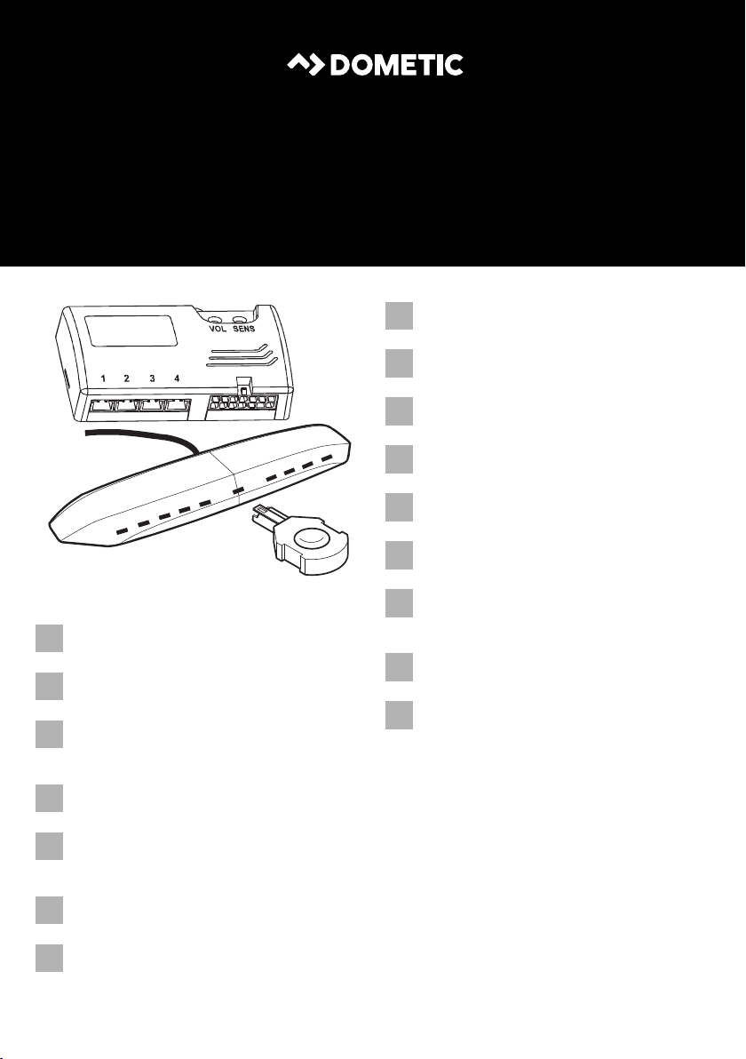
3 Scope of delivery . . . . . . . . . . . . . . . . . . . . . . . . . . . . . . . . . . . . . . . . . . . . . . .5
4 Accessories . . . . . . . . . . . . . . . . . . . . . . . . . . . . . . . . . . . . . . . . . . . . . . . . . . . .5
5 Intended use . . . . . . . . . . . . . . . . . . . . . . . . . . . . . . . . . . . . . . . . . . . . . . . . . . .5
6 Instructions before installation . . . . . . . . . . . . . . . . . . . . . . . . . . . . . . . . . . . . .6
7 Installing the blind spot aid. . . . . . . . . . . . . . . . . . . . . . . . . . . . . . . . . . . . . . . .7
8 Connecting the blind spot assistant. . . . . . . . . . . . . . . . . . . . . . . . . . . . . . . . .7
9 Detection range . . . . . . . . . . . . . . . . . . . . . . . . . . . . . . . . . . . . . . . . . . . . . . . .8
10 Setting the system. . . . . . . . . . . . . . . . . . . . . . . . . . . . . . . . . . . . . . . . . . . . . . .9
11 Using the blind spot assistant . . . . . . . . . . . . . . . . . . . . . . . . . . . . . . . . . . . . .10
12 Troubleshooting . . . . . . . . . . . . . . . . . . . . . . . . . . . . . . . . . . . . . . . . . . . . . . . 11
13 Warranty . . . . . . . . . . . . . . . . . . . . . . . . . . . . . . . . . . . . . . . . . . . . . . . . . . . . .13
14 Disposal. . . . . . . . . . . . . . . . . . . . . . . . . . . . . . . . . . . . . . . . . . . . . . . . . . . . . .13
15 Technical data . . . . . . . . . . . . . . . . . . . . . . . . . . . . . . . . . . . . . . . . . . . . . . . . .13
1 Explanation of symbols
WARNING!
!
A
Safety instruction: Indicates a hazardous situation that, if not avoided,
could result in death or serious injury.
NOTICE!
Indicates a situation that, if not avoided, can result in property damage.
3
Page 6

EN
Safety and installation instructions MWE4104
NOTE
I
Supplementary information for operating the product.
2 Safety and installation instructions
The following texts are only a supplement to the illustrations on the
supplementary sheet. They do not contain the full installation and
operating instructions. Please observe the illustrations on the
supplementary sheet.
Please observe the prescribed safety instructions and stipulations from the
vehicle manufacturer and service workshops.
Observe the applicable legal regulations.
The manufacturer accepts no liability for damage in the following cases:
• Damage to the product resulting from mechanical influences and incorrect
connection voltage
• Alterations to the product without express permission from the manufacturer
• Use for purposes other than those described in the operating manual
WARNING!
!
• Secure the parts of the blind spot assistant which are installed in the
vehicle in such a way that they cannot become loose under any circumstances (sudden braking, accidents) and cause injuries to the
occupants of the vehicle.
• Do not install the parts of the blind spot assistant anywhere in the vehicle where an airbag may open. This could cause injury if the airbag
deploys.
• The blind spot assistant is intended as an additional aid, which means
it does not relieve you of the obligation to take due care when maneuvring.
A
4
NOTICE!
• If you would like to install the sensors on metal bumpers, you will
require suitable adapters (not included in the scope of delivery).
• Do not expose the control electronics to dampness.
• Do not install the control electronics near any other control modules.
• The sensors may not cover signal lamps.
Page 7
EN
MWE4104 Scope of delivery
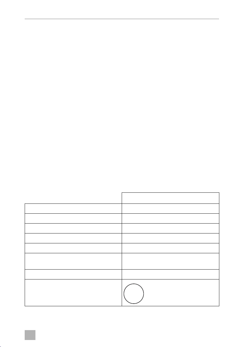
3Scope of delivery
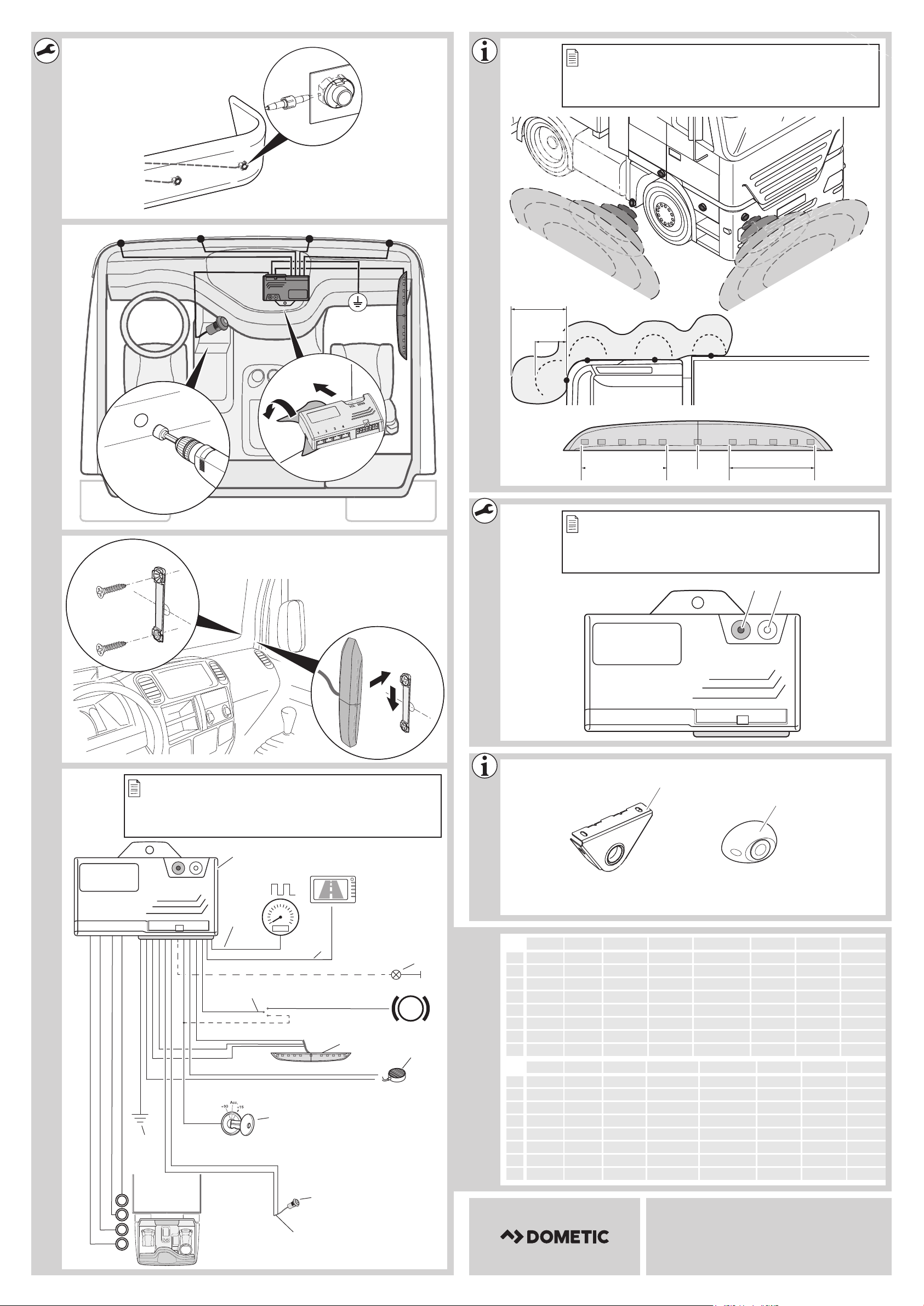
See fig. 1
No. Quantity Description Ref. no.
1 1 Control electronics 9101500080
2 1 Control electronics connection cable
3 1 LED display 9101500077
4 1 Switch 9101500066
5 4 Ultrasonic sensors with connection cable 9101500076
6 4 0° sensor holder with cover ring
7 4 12° sensor holder with cover ring
8 1 Fastening material
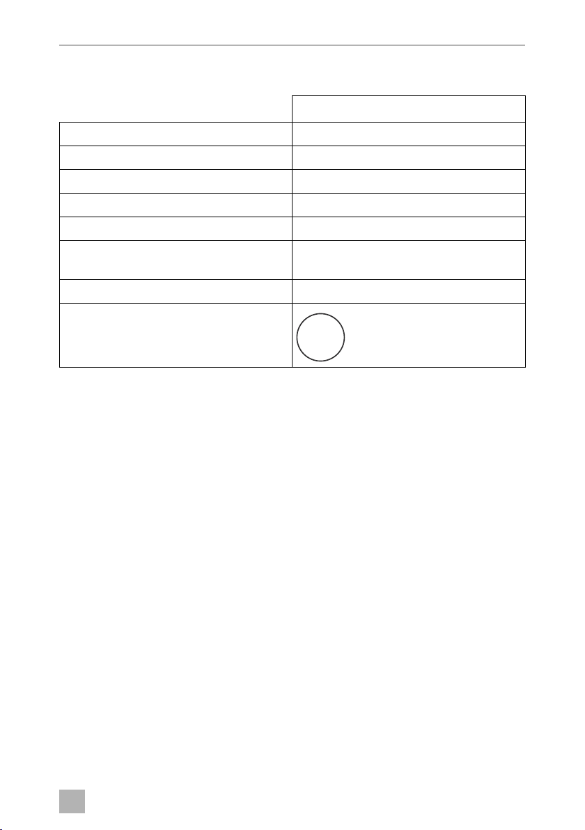
4Accessories
Available as accessories (not included in the scope of delivery):
Description Ref. no.
Sensor holder for metal bumper 9101500015
Subframe sensor holder (fig. d 1) 9101500078
Rubber sensor holder for surface mounting (fig. d 2) 9101500071
Loudspeaker MWD-900
5 Intended use
Dometic MWE4104 (ref. no. 9600024659) is a blind spot assistant based on ultrasound. When maneuvring, it monitors the space around the vehicle and provides an
audible and visible warning signal for any obstacles it detects.
MWE4104 is designed for installation in commercial vehicles.
5
Page 8

EN
Instructions before installation MWE4104
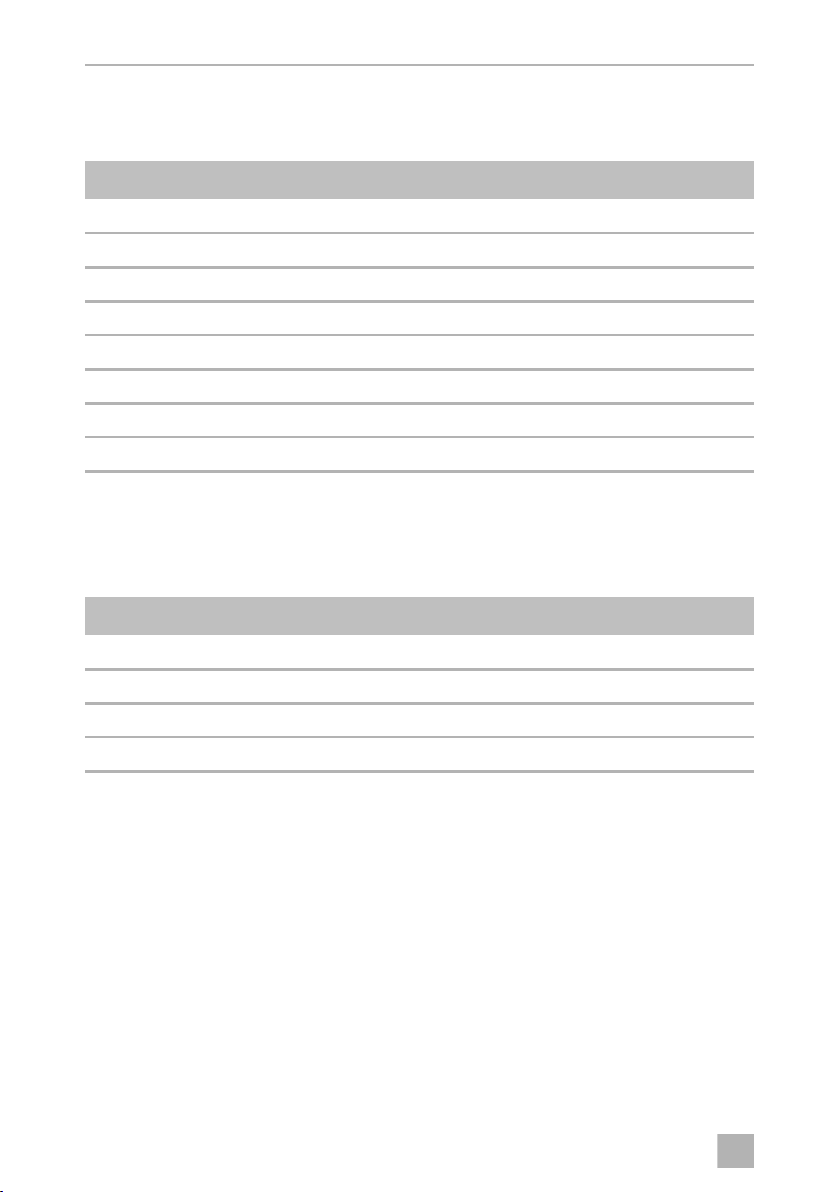
6 Instructions before installation
6.1 Painting the sensors
See fig. 2
NOTE
I
6.2 Determining the place of installation for the sensors
See fig. 3 to fig. 5
I
The sensors may be painted. The manufacturer recommends having the
sensors painted by a specialist workshop.
NOTE
The sensors must be correctly aligned for the device to work properly.
•
Do not install any other attachments in the detection area directly
around the sensor. Attachments in the detection area can lead to
reflections and errors.
•
Do not aim the sensors directly at the ground. If the sensors are
aimed directly at the ground, bumps may be displayed as an obstacle, for example.
•
Do not aim the sensors too far up. If the sensors point too far up,
obstacles will not be detected at all.
Note the following during installation:
• The area around the sensors must be free from other objects.
• The distance from the sensors to the ground when horizontally aligned should be
at least 45 cm and a maximum of 120 cm (fig. 3).
• Note that the alignment of the sensor depends on the installation height.
According to the table in fig. 3, select the sensor holder with the suitable angle.
Supplementary to fig. 5
➤ Observe the intervals between sensors.
NOTE
I
6
You can also distribute the sensors as shown in alternative B and C.
Page 9
EN
MWE4104 Installing the blind spot aid
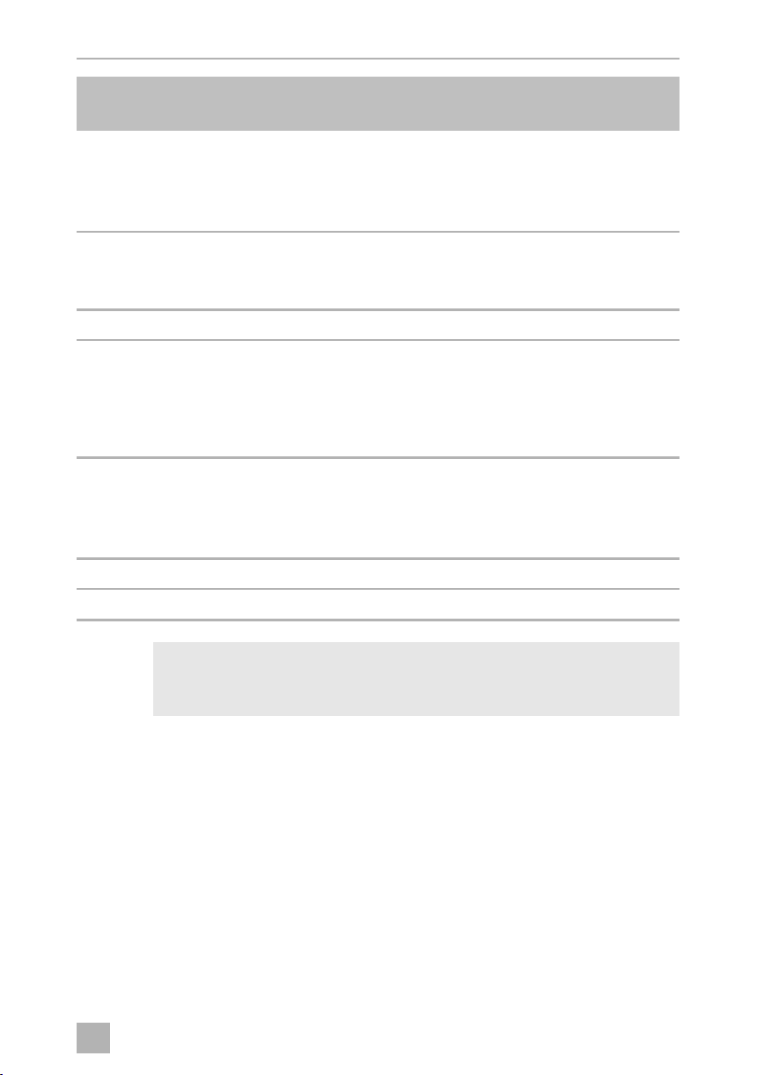
7 Installing the blind spot aid
See fig. 6 to fig. 0
Supplementary to fig. b
NOTICE! Risk of malfunction!
A
➤ Push the sensor holders into the holes until they lock into place.
Align the sensor holders so that the fastening lugs are horizontal.
The detection range of the sensors is larger horizontally than it is vertically. If the sensors are not level, the ground may be detected.
8 Connecting the blind spot assistant
See fig. a
No. Description
1 Control electronics –
2 Yellow/black cable: Connection to the cruise control
(4 pulses every 1 m, square wave, amplitude 5 – 32 V)
If no speed signal is available the system can be activated by the
indicators only.
3 Red/gray cable: Activating a video system.
Connect the red/grey cable to the activation trigger (rear) of the
video system.
4 White/blue cable: Connection to parking brake (see below)
switches the system off as soon as a ground signal is present
If not connected to the parking brake the wire must be connected
to ignition power.
5 Connection to LED display:
Black cable
White cable
Red cable
6 Connection to external loudspeaker (accessory)
Yellow cable
Blue cable
7 Blue/black cable: Connection to ignition 8
Plug socket
for plug
14
13
12
3
4
10
9
2
7
Page 10

EN
Detection range MWE4104
No. Description
8 Yellow/blue cable: Connection to turn indicator.
Activates the signal of the red/gray cable (trigger signal to e.g.
activate a video system).
If not connected to the turn indicator it must be connected to
12 V/24 V!
9 Switch connection:
Black cable
White cable
Red cable not connected
10 Sensors –
11 Brown cable: Connection to ground 1
NOTE
I
The manufacturer recommends applying some grease to the sensor
plug connections (not on the control module).
9Detection range
See fig. b
Plug socket
for plug
7
5
6
–
The detection range of the blind spot assistant is divided into two zones:
• Zone 1
Nearly all objects in this zone are displayed.
The orange LEDs light up in the LED display.
Every two seconds, a beep sounds.
• Stop zone (2)
If there are objects in this zone, the blind spot assistant emits a beep once a sec-
ond, warning you to stop.
The red LEDs light up in the LED display.
Virtually all objects are displayed in this zone, but some objects may end up in
the blind spot of the sensors.
8
Page 11

EN
MWE4104 Setting the system
10 Setting the system
See fig. c
WARNING!
!
The control electronics have the following control elements:
I
Setting the detection range of the sensors
➤ Press “VOL” briefly to switch the detection range.
The detection ranges switch in the order of “80 cm – 100 cm – 120 cm – 80 cm
…”.
Incorrect settings can impair the operational safety.
No. in fig. c Description
1 “VOL” button
2 “SENS” button
NOTE
If an external loudspeaker is connected and switched on, the acknowledgement tones of the internal loudspeaker of the LED display are emitted after a time delay on the external speaker.
✓ The
Switching the internal loudspeaker of the LED display on and off
I
➤ Press the “VOL” button for approx. 3 s.
✓ The LED display acknowledges whether the loudspeaker of the LED display is
LED display acknowledges the selected detection range with an acoustic
sig-nal:
– One short beep: 80 cm
– Two short beeps: 100 cm (default setting)
– Three short beeps: 120 cm
NOTE
When an external loudspeaker is connected, it is not switched on and
off as well.
switched on or off with an acoustic signal:
– three fast short beeps: off
– three short beeps: on
9
Page 12

EN
Using the blind spot assistant MWE4104
Setting the sensitivity of the sensors
➤ Press the “SENS” button briefly to switch to the sensitivity.
The sensitivity switches in the order “Low – Medium – High – Low …”.
✓ The LED display acknowledges the selected sensitivity with an acoustic signal:
– a short beep: low
– two short beeps: medium
– three short beeps: high (default setting)
Mode setting “camera activation” and “audio activation”
• Camera activation (default setting):
A long beep confirms activation of the camera mode. Trigger output is the re
ey wire. The system indicates an obstacle by a 2 s beep once only and acti-
gr
vates the connected video system.
• Audio activation (option):
10 short beeps confirm activation of the audio mode.
The system indicates an obstacle by
– one beep every 2 s in a range of 100 cm to 60 cm
– one beep per second in a range of 60 cm to 0 cm
d/
11 Using the blind spot assistant
The sensors are activated automatically:
• when the ignition is turned on
• when the parking brake is released
(if the parking brake is connected to plug socket 12 of the plug.)
• when the turn indicator is activated
They stay active as long as the speed stays under 15 km/h and the turn indicator is
activated. The blue LED in the LED display lights up.
As soon as there is an obstacle within the detection range, the LEDs in the
LED display light up and a signal tone is emitted.
As you approach, the different coloured LEDs show up in the LED display which zone
the obstacle is in, thereby indicating approximately the how far away it is.
Be very careful the first time you use the system, until you are familiar with the various
sequences with the LEDs in the LED display.
10
Page 13

EN
MWE4104 Troubleshooting
WARNING!
!
Stop the vehicle immediately and investigate the situation (getting out if
necessary), if the following happens while you are maneuvring:
the device first indicates an obstacle and the tone sequence speeds up
normally (e.g. from slow to medium) when maneuvring. The signal tone
suddenly slows down, or no obstacle is indicated at all.
This means that the original obstacle is in the blind spot of the sensors
(construction-related characteristic), and there is still a potential for
collision.
11.1 Switching off the system
The system can be switched off using the switch (fig. 1 4).
11.2 Using the camera (accessory)
The camera is activated when the vehicle speed drops below 15 km/h and the turn
indicator is activated.
The camera is switched off when the vehicle speed exceeds 15 km/h or when the
turn indicator is deactivated.
12 Troubleshooting
If a fault occurs, the blue LED flashes in the LED display.
The device shows no function.
The blue/black or brown cable for the voltage supply are not making contact.
➤ Check the connections are secure.
The white/blue cable for the parking brake is not receiving a positive signal.
➤ Check whether the white/blue cable for the deactivated parking brake has a pos-
itive signal (see chapter “Connecting the blind spot assistant” on page 7).
The system plug is not connected or not correctly plugged into the control
electronics.
➤ Check the system plugs and make sure they lock into place.
11
Page 14

EN
Troubleshooting MWE4104
Low error tone for three seconds after switching on the ignition.
One or more sensors are defective or no longer connected to the control
electronics.
After the low tone, the loudspeaker emits the same number of beeps as the number
of the defective sensor, e. g. two beeps for sensor 2.
If more than one sensor is defective, they are shown in succession.
The LED display also indicates the defective sensor (fig. 5; sensor 1 has the shortest
connection cable, sensor 4 the longest):
• Upper orange LED: Sensor 1
• Lower orange LED: Sensor 2
• Upper red LED: Sensor 3
•Lower red LED: Sensor 4
➤ Check the plugs and make sure they lock into place.
➤ Replace the defective sensor(s).
NOTICE!
A
Device indicates obstacles incorrectly
The system does not work if one or more sensors are defective.
False alarms may have the following causes:
• Dirt or frost on the sensors.
➤ Clean the sensors.
• The sensors were incorrectly installed.
➤ Adjust the position of the sensors (fig. 3).
➤ If necessary, set the detection range of the sensors (see chapter “Setti
detection range of the
➤ If necessary, set the sensitivity of the sensors (chapter “Setting the sensitivity of
the sensors” on page 10).
• The sensors are in contact with the chassis.
➤ Disconnect the sensors from the chassis and secure the sensor correctly in the
sensor holder.
sensors” on page 9).
ng the
12
Page 15
EN
MWE4104 Warranty
13 Warranty
The statutory warranty period applies. If the product is defective, please contact the
manufacturer's branch in your country (see the back of the instruction manual for the
addresses) or your retailer.
For repair and warranty processing, please send the following items:
• Defect components
• A copy of the receipt with purchasing date
• A reason for the claim or description of the fault
14 Disposal
➤ Place the packaging material in the appropriate recycling waste bins wherever
possible.
If you wish to finally dispose of the product, ask your local recycling centre
or specialist dealer for details about how to do this in accordance with the
M
applicable disposal regulations.
15 Technical data
MWE4104
Ref. no.: 9600024659
Detection range: approx. 0.15 m up to 1.20 m
Ultrasound frequency: 40 kHz
Input voltage: 10 – 32 V
Current: Max. 200 mA
Connection voltage for sirens or camera
(accessory):
Operating temperature: –25 °C to +85 °C
Certification:
12 – 24 V
E8
13
Page 16

DE
Erklärung der Symbole MWE 4104
Bitte lesen Sie diese Anleitung vor Einbau und Inbetriebnahme sorgfältig
durch und bewahren Sie sie auf. Geben Sie sie im Falle einer Weitergabe
des Produktes an den Nutzer weiter.
Inhaltsverzeichnis
1 Erklärung der Symbole . . . . . . . . . . . . . . . . . . . . . . . . . . . . . . . . . . . . . . . . . .14
2 Sicherheits- und Einbauhinweise . . . . . . . . . . . . . . . . . . . . . . . . . . . . . . . . . .15
3 Lieferumfang . . . . . . . . . . . . . . . . . . . . . . . . . . . . . . . . . . . . . . . . . . . . . . . . . . 16
4 Zubehör. . . . . . . . . . . . . . . . . . . . . . . . . . . . . . . . . . . . . . . . . . . . . . . . . . . . . .16
5 Bestimmungsgemäßer Gebrauch . . . . . . . . . . . . . . . . . . . . . . . . . . . . . . . . .16
6 Hinweise vor dem Einbau. . . . . . . . . . . . . . . . . . . . . . . . . . . . . . . . . . . . . . . . 17
7 Toter-Winkel-Assistent montieren . . . . . . . . . . . . . . . . . . . . . . . . . . . . . . . . .18
8 Toter- Winkel-Assistent anschließen . . . . . . . . . . . . . . . . . . . . . . . . . . . . . . . 18
9 Erfassungsbereich. . . . . . . . . . . . . . . . . . . . . . . . . . . . . . . . . . . . . . . . . . . . . .19
10 System einstellen. . . . . . . . . . . . . . . . . . . . . . . . . . . . . . . . . . . . . . . . . . . . . . 20
11 Toter-Winkel-Assistent benutzen . . . . . . . . . . . . . . . . . . . . . . . . . . . . . . . . . 22
12 Fehler suchen . . . . . . . . . . . . . . . . . . . . . . . . . . . . . . . . . . . . . . . . . . . . . . . . 23
13 Gewährleistung. . . . . . . . . . . . . . . . . . . . . . . . . . . . . . . . . . . . . . . . . . . . . . . 24
14 Entsorgung . . . . . . . . . . . . . . . . . . . . . . . . . . . . . . . . . . . . . . . . . . . . . . . . . . 24
15 Technische Daten . . . . . . . . . . . . . . . . . . . . . . . . . . . . . . . . . . . . . . . . . . . . . 25
1 Erklärung der Symbole
WARNUNG!
!
A
14
Sicherheitshinweis: Nichtbeachtung kann zu Tod oder schwerer
Verletzung führen.
ACHTUNG!
Nichtbeachtung kann zu Materialschäden führen und die Funktion des
Produktes beeinträchtigen.
Page 17

DE
MWE4104 Sicherheits- und Einbauhinweise
HINWEIS
I
Ergänzende Informationen zur Bedienung des Produktes.
2 Sicherheits- und Einbauhinweise
Die folgenden Texte ergänzen die Abbildungen auf dem Beiblatt lediglich.
Sie alleine sind keine vollständigen Einbau- und Bedienhinweise! Bitte
beachten Sie unbedingt die Abbildungen auf dem Beiblatt!
Beachten Sie die vom Fahrzeughersteller und vom Kfz-Handwerk vorgeschriebenen Sicherheitshinweise und Auflagen!
Beachten Sie die geltenden gesetzlichen Vorschriften.
Der Hersteller übernimmt in folgenden Fällen keine Haftung für Schäden:
• Beschädigungen am Produkt durch mechanische Einflüsse und falsche
Anschlussspannung
• Veränderungen am Produkt ohne ausdrückliche Genehmigung vom Hersteller
• Verwendung für andere als die in der Anleitung beschriebenen Zwecke
WARNUNG!
!
• Befestigen Sie die im Fahrzeug montierten Teile des Toter-WinkelAssistenten so, dass sie sich unter keinen Umständen (scharfes
Abbremsen, Verkehrsunfall) lösen und zu Verletzungen der
Fahrzeuginsassen führen können.
• Montieren Sie die im Fahrzeug montierten Teile des Toter-WinkelAssistenten nicht im Wirkungsbereich eines Airbags. Sonst besteht
Verletzungsgefahr, wenn der Airbag auslöst.
• Der Toter-Winkel-Assistent soll Sie zusätzlich unterstützen, d. h. das
Gerät entbindet Sie nicht von Ihrer besonderen Vorsichtspflicht beim
Rangieren.
A
ACHTUNG!
• Wenn Sie die Sensoren in Metall-Stoßfänger montieren möchten,
benötigen Sie geeignete Adapter (nicht im Lieferumfang enthalten).
• Die Steuerelektronik darf keiner Feuchtigkeit ausgesetzt sein.
• Die Steuerelektronik darf nicht in der Nähe von anderen Steuermodulen montiert werden.
• Die Sensoren dürfen keine Signallampen verdecken.
15
Page 18
DE
Lieferumfang MWE4104
3 Lieferumfang
Siehe Abb. 1
Nr. Menge Bezeichnung Art.-Nr.
1 1 Steuerelektronik 9101500080
2 1 Anschlusskabel Steuerelektronik
3 1 LED-Display 9101500077
4 1 Schalter 9101500066
5 4 Ultraschall-Sensoren mit Anschlusskabel 9101500076
6 4 Sensorhalter 0° mit Abdeckring
7 4 Sensorhalter 12° mit Abdeckring
8 1 Befestigungsmaterial
4Zubehör
Als Zubehör erhältlich (nicht im Lieferumfang enthalten):
Bezeichnung Art.-Nr.
Sensorhalter für Stoßfänger aus Metall 9101500015
Unterbausensorhalter (Abb.d 1) 9101500078
Gummisensorhalter für Aufbaumontage (Abb. d 2) 9101500071
Lautsprecher MWD-900
5 Bestimmungsgemäßer Gebrauch
Dometic MWE4104 (Art.-Nr. 9600024659) ist ein Toter-Winkel-Assistent auf
Ultraschallbasis. Er überwacht beim Rangieren den Raum um das Fahrzeug und
warnt akustisch vor Hindernissen, die durch das Gerät erfasst werden.
MWE4104 ist zum Einbau in Nutzfahrzeuge ausgelegt.
16
Page 19

DE
MWE4104 Hinweise vor dem Einbau
6 Hinweise vor dem Einbau
6.1 Sensoren lackieren
Siehe Abb. 2
HINWEIS
I
6.2 Einbauort für die Sensoren festlegen
Siehe Abb. 3 bis Abb. 5
I
Die Sensoren dürfen lackiert werden. Der Hersteller empfiehlt, die
Lackierung der Sensoren von einer Fachwerkstatt vornehmen zu lassen.
HINWEIS
Wichtig für die einwandfreie Funktion des Gerätes ist die korrekte
Ausrichtung der Sensoren.
• Installieren Sie im Erfassungsbereich direkt um den Sensor herum
keine weiteren Anbauteile. Anbauteile im Erfassungsbereich können
zu Reflexionen und Fehlerfassungen führen.
• Richten Sie die Sensoren nicht direkt auf den Boden aus. Wenn die
Sensoren direkt auf den Boden ausgerichtet sind, können z. B.
Bodenunebenheiten als Hindernis angezeigt werden.
• Richten Sie die Sensoren nicht zu weit nach oben aus. Wenn die Sensoren zu weit nach oben ausgerichtet sind, werden vorhandene Hindernisse nicht erkannt.
Beachten Sie Folgendes bei der Montage:
• Der Bereich um die Sensoren muss frei von anderen Objekten sein.
• Der Abstand der Sensoren zum Boden sollte bei horizontaler Ausrichtung
mindestens 45 cm und maximal 120 cm betragen (Abb. 3).
• Beachten Sie, dass die Ausrichtung des Sensors von der Montagehöhe abhängt.
Wählen Sie entsprechend der Tabelle in Abb. 3 den Sensorhalter mit dem passenden Winkel aus.
Ergänzung zu Abb. 5
➤ Beachten Sie die Abstände der Sensoren.
17
Page 20

DE
Toter-Winkel-Assistent montieren MWE4104
HINWEIS
I
Sie können die Sensoren auch so verteilen wie in Alternative B und C
gezeigt.
7 Toter-Winkel-Assistent montieren
Siehe Abb. 6 bis Abb. 0
Ergänzung zu Abb. b
ACHTUNG! Gefahr von Funktionsstörung!
A
➤ Schieben Sie die Sensorhalter in die Bohrungen, bis sie einrasten.
Richten Sie die Sensorhalter so aus, dass die Befestigungsnasen waagerecht stehen.
Der Erfassungsbereich der Sensoren ist horizontal größer als vertikal.
Wenn die Sensoren nicht waagerecht ausgerichtet sind, kann es zur
Erfassung des Bodens kommen.
8 Toter- Winkel-Assistent anschließen
Siehe Abb. a
Nr. Bezeichnung
1 Steuerelektronik –
2 Gelb/schwarze Ader: Anschluss an Geschwindigkeitssignal
(4 Impulse pro 1 m, Rechteckwelle, Amplitude 5 – 32 V)
Wenn kein Geschwindigkeitssignal verfügbar ist, kann das Sys-
tem nur durch die Blinker aktiviert werden.
3 Rot/graue Ader: Aktivieren eines Videosystems.
Verbinden Sie die rot/graue Ader mit dem Aktivierungsanschluss
(Rückseite) des Videosystems.
4 Weiß/blaue Ader: Anschluss an Feststellbremse (siehe unten)
Schaltet das System ab, sobald ein Massesignal anliegt.
Wenn die Ader nicht an die Feststellbremse angeschlossen wird,
muss sie an die Zündung angeschlossen werden.
18
Steckplatz
Stecker
14
13
12
Page 21
DE
MWE4104 Erfassungsbereich
Nr. Bezeichnung
5 Anschluss LED-Display:
schwarze Ader
weiße Ader
rote Ader
6 Anschluss externer Lautsprecher (Zubehör)
Gelbe Ader
Blaue Ader
7 Blau/schwarze Ader: Anschluss an Zündung 8
8 Gelb/blaue Ader: Anschluss an den Blinker.
Aktiviert das Signal der rot/grauen Ader (Steuersignal beispielsweise zum Aktivieren des Videosystems).
Wenn kein Anschluss an den Blinker erfolgt, muss die Ader an
12 V/24 V angeschlossen werden!
9 Anschluss Schalter:
schwarze Ader
weiße Ader
rote Ader nicht angeschlossen
10 Sensoren –
11 Braune Ader: Anschluss an Masse 1
Steckplatz
Stecker
3
4
10
9
2
7
5
6
–
HINWEIS
I
Der Hersteller empfiehlt, etwas Fett in die Sensor-Steckverbindungen
(nicht am Steuermodul) zu geben.
9 Erfassungsbereich
Siehe Abb. b
Der Erfassungsbereich des Toter-Winkel-Assistenten ist in zwei Zonen aufgeteilt:
•Zone 1
In dieser Zone werden nahezu alle Objekte angezeigt.
Die orangefarbenen LEDs im LED-Display leuchten.
Alle zwei Sekunden ertönt ein Piepton.
19
Page 22

DE
System einstellen MWE4104
•Stoppzone (2)
Objekte in dieser Zone führen dazu, dass der Toter-Winkel-Assistent durch einen
Piepton pro Sekunde „Stopp“ signalisie
Die rot
en LEDs im LED-Display leuchten.
In dieser Zone werden nahezu alle Objekte angezeigt, aber es können Gegenstände in den toten Winkel der Sensoren geraten.
rt.
10 System einstellen
Siehe Abb. c
WARNUNG!
!
Die Steuerelektronik besitzt folgende Bedienelemente:
Nr. in Abb. c Bezeichnung
Unsachgemäße Einstellungen können die sichere Funktion
beeinträchtigen.
1 Taste „VOL“
2 Taste „SENS“
HINWEIS
I
Erfassungsbereich der Sensoren einstellen
➤ Drücken Sie die Taste „VOL“ kurz, um den Erfassungsbereich umzuschalten.
Die Erfassungsbereiche werden in der Reihenfolge „80 cm – 100 cm – 120 cm –
80 cm…“ umgeschaltet.
✓ Das LED-Disp
akustisches Signal:
– ein kurzer Piepton: 80 cm
– zwei kurze Pieptöne: 100 cm (Werkseinstellung)
– drei kurze Pieptöne: 120 cm
Wenn ein externer Lautsprecher angeschlossen und eingeschaltet ist,
werden die Quittiertöne des internen Lautsprechers des LED-Displays
zeitversetzt auf den externen Lautsprecher ausgegeben.
lay quittiert den gewählten Erfassungsbereich durch ein
20
Page 23

DE
MWE4104 System einstellen
Internen Lautsprecher des LED-Displays ein- und ausschalten
HINWEIS
I
➤ Drücken Sie die Taste „VOL“ für ca. 3 s.
✓ Das LED-Display quittiert durch ein akustisches Signal, ob der Lautsprecher des
LED-Displays ein- oder ausgeschaltet ist:
– drei schnelle kurze Pieptöne: aus
– drei kurze Pieptöne: ein
Empfindlichkeit der Sensoren einstellen
➤ Drücken Sie die Taste „SENS“ kurz, um die Empfindlichkeit umzuschalten.
Die Empfindlichkeit wird in der Reihenfolge „Niedrig – Mittel – Hoch – Ni
…“ umgesch
Wenn ein externer Lautsprecher angeschlossen ist, wird dieser nicht
mit ein- oder ausgeschaltet.
edrig
altet.
✓ Das LED-Display quittiert die gewählte Empfindlichkeit durch ein akusti
Signal:
ein kurzer Piepton: niedrig
–
– zwei kurze Pieptöne: mittel
– drei kurze Pieptöne: hoch (Werkseinstellung)
Einstellung der Betriebsarten „Kamera-Aktivierung“ und „Audio-Aktivierung“
• Kamera-Aktivierung (Werkseinstellung):
Ein kurzer Piepton bestätigt die Aktivierung der Kamerabetriebsart. Der Aus-
gang für die Auslösung ist die rot/graue Ader. Das System zeigt ein Hindernis
durch einen 2 Sekunden langen Piepton einmalig an und aktiviert das angeschlossene Videosystem.
• Audio-Aktivierung (Option):
10 kurze Pieptöne bestätigen die Aktivierung der Audiobetriebsart.
Das System zeigt ein Hindernis an durch
– einen Piepton alle 2 s bei einem Abstand von 100 cm bis 60 cm
– einen Piepton pro Sekunde bei einem Abstand von 60 cm bis 0 cm
sches
21
Page 24

DE
Toter-Winkel-Assistent benutzen MWE4104
11 Toter-Winkel-Assistent benutzen
Die Sensoren werden automatisch aktiviert:
• wenn die Zündung eingeschaltet ist
• wenn die Feststellbremse gelöst wird
(Sofern die Feststellbremse an Steckplatz 12 des Steckers angeschlossen ist.)
• wenn der Blinker betätigt wird
Sie bleiben aktiviert, solange die Geschwindigkeit weniger als 15 km/h beträgt oder
solange der Blinker aktiviert ist. Die blaue LED im LED-Display leuchtet.
Sobald sich ein Hindernis im Erfassungsbereich befindet, leuchten die LEDs im
LED-Display und ein sich gleichmäßig wiederholender Signalton ertönt.
Beim Heranfahren zeigen die verschiedenfarbigen LEDs im LED-Display an, in
welcher Zone sich das Hindernis gerade befindet und somit wie weit es ungefähr
entfernt ist.
Gehen Sie bei der Erstinbetriebnahme äußerst vorsichtig vor, um sich mit der
Entfernungsangabe durch die LEDs im LED-Display vertraut zu machen.
WARNUNG!
!
Halten Sie das Fahrzeug sofort an und prüfen Sie die Situation (ggf. aussteigen), wenn beim Rangieren Folgendes geschieht:
Beim Rangieren zeigt das Gerät zunächst ein Hindernis an, und die Tonfolge wird ganz normal schneller (z. B. Wechsel von der langsamen in
die schnelle Tonfolge). Plötzlich springt der Signalton auf die langsame
Tonfolge um oder zeigt überhaupt kein Hindernis mehr an.
Dies bedeutet, dass sich das ursprüngliche Hindernis nicht mehr im
Erfassungsbereich der Sensoren befindet (bauartbedingt), aber immer
noch angefahren werden kann.
11.1 System abschalten
Mit dem Schalter (Abb. 1 4) kann das System ausgeschaltet werden.
11.2 Kamera (Zubehör) benutzen
Die Kamera wird aktiviert, wenn die Fahrzeuggeschwindigkeit weniger als 15 km/h
beträgt oder wenn der Blinker aktiviert wird.
Die Kamera wird abgeschaltet, wenn die Geschwindigkeit 15 km/h überschreitet
oder wenn der Blinker deaktiviert wird.
22
Page 25

DE
MWE4104 Fehler suchen
12 Fehler suchen
Wenn ein Fehler auftritt, blinkt die blaue LED im LED-Display.
Gerät zeigt keine Funktion
Die blau/schwarze oder die braune Ader für die Spannungsversorgung haben
keinen Kontakt.
➤ Prüfen Sie die Verbindungen auf sicheren Kontakt.
Die weiß/blaue Ader für die Feststellbremse hat kein positives Signal.
➤ Prüfen Sie, ob die weiß/blaue Ader deaktivierter Feststellbremse ein positives
Signal hat (siehe Kapitel „Toter- Winkel-Assistent anschließen“ auf Seite 18).
Der Systemstecker ist nicht oder nicht richtig in die Steuerelektronik eingesteckt.
➤ Prüfen Sie den Systemstecker und stecken Sie ihn ggf. so auf, dass er einrastet.
Tiefer Fehlerton für drei Sekunden nach Einschalten der Zündung
Ein oder mehrere Sensoren sind defekt oder nicht mehr mit der Steuerelektronik
verbunden.
Nach dem tiefen Ton gibt der Lautsprecher durch die Anzahl von Pieptönen die
Nummer des defekten Sensors an, z. B. zwei Pieptöne für Sensor 2.
Wenn mehr als ein Sensor defekt ist, werden diese nacheinander angezeigt.
Außerdem zeigt das LED-Display den defekten Sensor an (Abb. 5; Sensor 1 hat das
kürzeste Anschlusskabel, Sensor 4 das längste):
• obere orangefarbene LED: Sensor 1
• untere orangefarbene LED: Sensor 2
• obere rote LED: Sensor 3
• untere rote LED: Sensor 4
➤ Prüfen Sie die Stecker und stecken Sie sie ggf. so auf, dass sie einrasten.
➤ Tauschen Sie den oder die defekten Sensoren aus.
ACHTUNG!
A
Das System funktioniert nicht, wenn ein oder mehrere Sensoren defekt
sind.
23
Page 26

DE
Gewährleistung MWE4104
Gerät meldet Hindernisse falsch
Folgende Ursachen können zu Fehlalarmen führen:
• Schmutz oder Eis auf den Sensoren.
➤ Reinigen Sie die Sensoren.
• Die Sensoren wurden falsch montiert.
➤ Passen Sie die Lage der Sensoren an (Abb. 3).
➤ Stellen Sie ggf. den Erfassungsbereich der Sensoren ein (siehe Kapitel
„Erfassungsbereich der Sensoren einstellen“ auf Seite 20).
➤ Stellen Sie ggf. die Empfindlichkeit der Sensoren ein (siehe Kapitel „Empfindlich-
keit der Sensoren einstellen“ auf Seite 21).
• Die Sensoren haben Kontakt mit dem Fahrzeugchassis.
➤ Trennen Sie die Sensoren vom Chassis und fixieren Sie den Sensor korrekt
Sensorhalter.
im
13 Gewährleistung
Es gilt die gesetzliche Gewährleistungsfrist. Sollte das Produkt defekt sein, wenden
Sie sich bitte an die Niederlassung des Herstellers in Ihrem Land (Adressen siehe
Rückseite der Anleitung) oder an Ihren Fachhändler.
Zur Reparatur- bzw. Gewährleistungsbearbeitung müssen Sie Folgendes einschicken:
• defekte Komponenten,
• eine Kopie der Rechnung mit Kaufdatum,
• einen Reklamationsgrund oder eine Fehlerbeschreibung.
14 Entsorgung
➤ Geben Sie das Verpackungsmaterial möglichst in den entsprechenden
Recycling-Müll.
Wenn Sie das Produkt endgültig außer Betrieb nehmen, informieren Sie
sich bitte beim nächsten Recyclingcenter oder bei Ihrem Fachhändler
M
über die zutreffenden Entsorgungsvorschriften.
24
Page 27
DE
MWE4104 Technische Daten
15 Technische Daten
MWE4104
Art.-Nr.: 9600024659
Erfassungsbereich: ca. 0,15 m bis zu 1,20 m
Ultraschallfrequenz: 40 kHz
Versorgungsspannung: 10 – 32 V
Stromaufnahme: maximal 200 mA
Anschlussspannung für Sirene oder Kamera
(Zubehör):
Betriebstemperatur: –25 °C bis +85 °C
Zulassung:
12 – 24 V
E8
25
Page 28

FR
Explication des symboles MWE4104
Veuillez lire attentivement cette notice avant le montage et la mise en
service. Veuillez ensuite la conserver. En cas de passer le produit, veuillez
le transmettre au nouvel acquéreur.
Table des matières
1 Explication des symboles . . . . . . . . . . . . . . . . . . . . . . . . . . . . . . . . . . . . . . . 26
2 Consignes de sécurité et instructions de montage. . . . . . . . . . . . . . . . . . . 27
3 Contenu de la livraison . . . . . . . . . . . . . . . . . . . . . . . . . . . . . . . . . . . . . . . . . 28
4 Accessoires . . . . . . . . . . . . . . . . . . . . . . . . . . . . . . . . . . . . . . . . . . . . . . . . . . 28
5 Usage conforme . . . . . . . . . . . . . . . . . . . . . . . . . . . . . . . . . . . . . . . . . . . . . . 29
6 Consignes préalables au montage. . . . . . . . . . . . . . . . . . . . . . . . . . . . . . . . 29
7 Montage de l'assistant d'angle mort . . . . . . . . . . . . . . . . . . . . . . . . . . . . . . 30
8 Raccordement de l'assistant d'angle mort . . . . . . . . . . . . . . . . . . . . . . . . . .31
9 Zone de détection . . . . . . . . . . . . . . . . . . . . . . . . . . . . . . . . . . . . . . . . . . . . 32
10 Réglage du système . . . . . . . . . . . . . . . . . . . . . . . . . . . . . . . . . . . . . . . . . . . 32
11 Utilisation de l'assistant d'angle mort . . . . . . . . . . . . . . . . . . . . . . . . . . . . . 34
12 Recherche des pannes . . . . . . . . . . . . . . . . . . . . . . . . . . . . . . . . . . . . . . . . . 35
13 Garantie. . . . . . . . . . . . . . . . . . . . . . . . . . . . . . . . . . . . . . . . . . . . . . . . . . . . . 37
14 Retraitement . . . . . . . . . . . . . . . . . . . . . . . . . . . . . . . . . . . . . . . . . . . . . . . . . 37
15 Caractéristiques techniques. . . . . . . . . . . . . . . . . . . . . . . . . . . . . . . . . . . . . 38
1 Explication des symboles
AVERTISSEMENT !
!
A
26
Consigne de sécurité : le non-respect de ces consignes peut entraîner
la mort ou de graves blessures.
AVIS !
Le non-respect de ces consignes peut entraîner des dommages
matériels et des dysfonctionnements du produit.
Page 29

FR
MWE4104 Consignes de sécurité et instructions de montage
REMARQUE
I
Informations complémentaires sur l'utilisation du produit.
2 Consignes de sécurité et instructions de
montage
Les textes suivants ne font que compléter les illustrations en annexe. Il ne
s'agit pas d'instructions complètes de montage et d'utilisation ! Veuillez
impérativement respecter les illustrations en annexe!
Respectez les consignes de sécurité et autres prescriptions imposées par
le fabricant du véhicule et par les professionnels de l’automobile !
Respectez les consignes légales en vigueur.
Le fabricant décline toute responsabilité pour des dommages dans les cas suivants :
• des sollicitations mécaniques et une tension de raccordement incorrecte ayant
endommagé le matériel
• des modifications apportées au produit sans autorisation explicite de la part du
fabricant
• une utilisation différente de celle décrite dans la notice
!
A
AVERTISSEMENT !
• Fixez les pièces de l'assistant d'angle mort installées dans le véhicule
de manière à ce qu’elles ne puissent en aucun cas se desserrer (freinage abrupt, accident) et risquer de causer des blessures aux
occupants du véhicule.
• N'installez pas les pièces de l'assistant d'angle mort dans le champ
d'action d'un airbag. Cela risquerait de blesser les passagers en cas
d'enclenchement de l'airbag.
• L'assistant d'angle mort doit vous apporter une aide supplémentaire,
c’est-à-dire que l’appareil ne vous dégage pas du devoir de prudence
qui vous incombe lorsque vous faites une manœuvre.
AVIS !
• Si vous souhaitez monter les détecteurs sur un pare-chocs métallique,
il vous faut les adaptateurs adéquats (non compris dans la livraison).
• Veillez à ce que l'électronique de commande ne soit pas exposée à
l'humidité.
27
Page 30
FR
Contenu de la livraison MWE4104
• L'électronique de commande ne doit pas être montée à proximité
d'autres modules de commande.
• Veillez à ce qu'aucun détecteur ne cache les lampes de signalisation.
3 Contenu de la livraison
Voir fig. 1
Nº Quantité Désignation N° de produit
1 1 Électronique de commande 9101500080
2 1 Câbles de raccordement de l'électronique de
commande
3 1 Affichage LED 9101500077
4 1 Commutateur 9101500066
5 4 Détecteurs à ultrasons avec câble de
raccordement
6 4 Support détecteur 0° avec anneau de couverture
7 4 Support détecteur 12° avec anneau de couver-
ture
9101500076
8 1 Matériel de fixation
4Accessoires
Disponibles en accessoires (non compris dans la livraison) :
Désignation N° de produit
Support détecteur pour pare-chocs en métal 9101500015
Support pour détecteurs encastrés (fig. d 1) 9101500078
Support pour détecteurs en caoutchouc pour montage (fig. d 2) 9101500071
Haut-parleur MWD-900
28
Page 31

FR
MWE4104 Usage conforme
5Usage conforme
Dometic MWE 4104 (n° d'article 9600024659) est un assistant d'angle mort utilisant
les ultrasons. Il surveille l’espace restant autour du véhicule lors d’une manœuvre et
émet un avertissement sonore lorsque des obstacles sont détectés par l’appareil.
MWE4104 est conçu pour être installé dans les véhicules utilitaires.
6 Consignes préalables au montage
6.1 Peindre les détecteurs
Voir fig. 2
REMARQUE
I
6.2 Déterminer l'emplacement de montage pour les
Voir fig. 3 à fig. 5
Les détecteurs peuvent être peints. Le fabricant recommande de faire
effectuer la peinture des détecteurs dans un garage spécialisé.
détecteurs
I
REMARQUE
Afin de permettre un fonctionnement parfait de l’appareil, il est important que les détecteurs soient correctement orientés.
• N’installez aucune autre pièce rapportée dans la zone de détection
directement autour du détecteur. La présence de pièces rapportées
dans la zone de détection peut entraîner des réflexions et
erreurs.
•
Ne dirigez pas les détecteurs directement vers le sol. Si les détecteurs sont orientés directement vers le sol, des irrégularités du sol par
exemple seront signalées comme obstacles.
• Ne dirigez pas les détecteurs trop vers le haut. Si les détecteurs sont
trop orientés vers le haut, les obstacles existants risquent de ne
être détectés.
des
pas
29
Page 32

FR
Montage de l'assistant d'angle mort MWE4104
Veuillez respecter les consignes suivantes lors du montage :
• La zone autour des détecteurs doit être libre et dépourvue d'autres objets.
• La distance séparant les détecteurs du sol doit être, avec une orientation horizontale, de 45 cm au minimum et de 120 cm au maximum (fig. 3).
• Veuillez noter que l'alignement du détecteur dépend de la hauteur de montage.
En fonction du tableau de la fig. 3, choisissez le support de détecteur avec
l’angle approprié.
Complément de la fig. 5
➤ Tenez compte de la distance entre les détecteurs.
REMARQUE
I
Vous avez la possibilité de répartir les détecteurs comme indiqué dans
l'alternative B et C.
7 Montage de l'assistant d'angle mort
Voir fig. 6 à fig. 0
Complément de la fig. b
AVIS ! Risque de dysfonctionnement !
A
➤ Faites glisser les supports de détecteurs dans les trous, jusqu'à ce qu'ils
s'enclenchent.
30
Orientez les supports de détecteurs de telle sorte que les taquets de
fixation soient à l’horizontale.
La plage de détection des détecteurs est plus large à l’horizontale qu’à
la verticale. Si les détecteurs ne sont pas de niveau, le sol peut être
détecté.
Page 33

FR
MWE4104 Raccordement de l'assistant d'angle mort
8 Raccordement de l'assistant d'angle
mort
Voir fig. a
Pos. Description
1 Électronique de commande –
2 Fil jaune/noir : raccordement à un signal de vitesse
(4 impulsions tous les 1 m, onde carrée, amplitude 5 – 32 V).
Si aucun signal de vitesse n’est disponible, le système ne peut
être activé que par les clignotants.
3 Fil rouge/gris : activation d’un système vidéo.
Raccordez le fil rouge/gris au déclencheur d’activation
(à l’arrière) du système vidéo.
4 Fil blanc/bleu : raccordement au frein de stationnement
(voir ci-dessous), arrête le système dès qu’un signal de masse est
détecté.
S’il n’est pas raccordé au frein de stationnement, le fil doit être
connecté à l’alimentation de l’allumage.
5 Raccordement de l'écran LED :
fil noir
fil blanc
fil rouge
6 Raccordement des haut-parleurs externes (accessoires)
Fil jaune
Fil bleu
7 Fil bleu/noir : raccordement à l'allumage 8
Emplacement
connecteur
14
13
12
3
4
10
9
2
8 Fil jaune/bleu : raccordement au clignotant.
Active le signal du câble rouge/gris (signal de déclenchement,
par exemple pour activer un système vidéo).
S’il n’est pas raccordé au clignotant, il doit être raccordé à une
alimentation 12 V/24 V !
9 Raccordement de commutateur :
fil noir
fil blanc
fil rouge non raccordé
7
5
6
–
31
Page 34

FR
Zone de détection MWE4104
Pos. Description
10 Détecteurs –
11 Câble marron : raccordement à la masse 1
REMARQUE
I
Le fabricant recommande d'appliquer un peu de graisse dans les prises
de raccordement des détecteurs (pas au niveau du module de commande).
Emplacement
connecteur
9 Zone de détection
Voir fig. b
La zone de détection de l'assistant d'angle mort est répartie en deux zones :
•Zone 1
Dans cette zone, presque tous les objets sont signalés.
Les LED orange sur l'écran LED s'allument.
Un signal sonore retentit toutes les deux secondes.
• Zone d'arrêt (zone 2)
Les objets présents dans cette zone déclenchent un signal sonore une fois par
seconde de l'assistant d'angle mort, signifiant « Stop »
es LED rouges sur l'écran LED s'allument.
L
Dans cette zone, presque tous les objets sont signalés, mais il est possible
des
objets se retrouvent dans l’angle mort des détecteurs.
.
que
10 Réglage du système
Voir fig. c
AVERTISSEMENT !
!
32
Des réglages non conformes peuvent affecter la sûreté du
fonctionnement.
Page 35

FR
MWE4104 Réglage du système
L'électronique de commande dispose des éléments suivants :
N° sur la fig. c Désignation
1Touche «VOL»
2 Touche « SENS »
REMARQUE
I
Réglage de la zone de détection des détecteurs
➤ Appuyez brièvement sur « VOL » pour commuter la zone de détection.
Les zones de détection commutent dans l'ordre « 80 cm – 100 cm – 120 cm –
80 cm … ».
Si un haut-parleur externe est connecté et allumé, les tonalités de
confirmation du haut-parleur interne de l'écran LED sont émis avec un
retard sur le haut-parleur externe.
✓ L'écran LED valid
– un bip bref : 80 cm
– deux bips brefs : 100 cm (réglage d’usine)
– trois bips brefs : 120 cm
Activation et désactivation du haut-parleur interne de l'écran LED
REMARQUE
I
➤ Appuyez sur la touche « VOL » pendant environ 3 s.
✓ L'écran LED confirme par un signal sonore que le haut-parleur de l'écran LED est
activé ou désactivé :
– trois bips brefs et rapides : éteint
– trois bips brefs : allumé
Réglage de la sensibilité des détecteurs
➤ Appuyez brièvement sur la touche « SENS » pour commuter la sensibilité.
La sensibilité commute dans l'ordre « Faible – Moyenne – Élevée – Faible … ».
Si un haut-parleur externe est raccordé, celui-ci n'est pas activé ou
désactivé simultanément.
e la zone de détection sélectionnée par un signal sonore :
33
Page 36

FR
Utilisation de l'assistant d'angle mort MWE4104
✓ L'écran LED valide la sensibilité sélectionnée par un signal sonore :
– un bip bref : faible
– deux bips brefs : moyen
– trois bips brefs : élevé (réglage d’usine)
Réglage du mode « activation caméra » et « activation audio »
• Activation caméra (réglage d’usine) :
Un long bip confirme l’activation du mode caméra. La sortie d’activation est le fil
rouge/gris. Le système n’émet qu’un seul bip sonore de 2 s pour signaler un
obstacle et active le système vidéo connecté.
• Activation audio (option) :
10 bips brefs confirment l’activation du mode audio.
Le système signale un obstacle par
– un bip toutes les 2 secondes sur une plage de 100 cm à 60 cm
– un bip par seconde sur une plage de 60 cm à 0 cm
11 Utilisation de l'assistant d'angle mort
Les détecteurs sont activés automatiquement lorsque :
• L'allumage est activé
• Le frein de stationnement est desserré
(si le frein de stationnement est raccordé à l'emplacement 12 du connecteur.)
• Le clignotant est activé
Ceux-ci restent actifs tant que la vitesse est inférieure à 15 km/h et tant que le clignotant est activé. La LED bleue de l’écran LED s’allume.
Dès qu’un obstacle se trouve dans la zone de détection, les LED de l’écran LED
s’allument et un bip retentit.
Lorsque vous approchez de l'obstacle, les LED de différentes couleurs de l'écran
LED indiquent la zone dans laquelle l'obstacle se trouve à ce moment et donc à
quelle distance approximative il se trouve.
Soyez prudent lors de la mise en service initiale afin de vous familiariser avec les
distances qui correspondent aux différentes LED sur l'écran LED.
34
Page 37

FR
MWE4104 Recherche des pannes
AVERTISSEMENT !
!
Arrêtez le véhicule et contrôlez immédiatement la situation (si nécessaire, descendez du véhicule) si les événements suivants se produisent
lors d’une manœuvre :
Lors d’une manœuvre, l’appareil indique d'abord un obstacle et la
fréquence des bips sonores augmente comme prévu (par exemple,
passage de la fréquence lente à la fréquence moyenne). Le signal sonore
passe tout à coup à la fréquence d'émission lente ou n’indique plus
aucun obstacle.
Ceci signifie que l’obstacle initial ne se trouve plus dans la zone de
détection des détecteurs (en raison de la forme des détecteurs), mais
qu’une collision reste possible.
11.1 Extinction du système
Le commutateur (fig. 1 4) permet d’éteindre le système.
11.2 Utilisation de la caméra (accessoires)
La caméra est activée lorsque la vitesse du véhicule est inférieure à 15 km/h et que le
clignotant est activé.
Elle est désactivée lorsque la vitesse est supérieure à 15 km/h ou lorsque le clignotant est désactivé.
12 Recherche des pannes
Lorsqu'une erreur survient, la LED bleue de l'écran LED clignote.
L’appareil ne semble pas fonctionner.
Le fil bleu/noir ou le fil marron pour l'alimentation électrique n'ont aucun contact.
➤ Vérifiez le bon contact entre les raccordements.
Le fil blanc/bleu pour le frein de stationnement n'a aucun signal positif.
➤ Vérifiez si le fil blanc/bleu du frein de stationnement désactivé a un signal positif
(voir chapitre « Raccordement de l'assistant d'angle mort », page 31).
Le connecteur du système n'est pas enfiché ou est mal enfiché dans l’électronique
de commande.
35
Page 38

FR
Recherche des pannes MWE4104
➤ Contrôlez le connecteur du système et, si nécessaire, enfichez-le de manière à ce
qu’il soit enclenché.
Bip d'erreur plus grave de trois secondes une fois que le contact est mis
Un ou plusieurs détecteurs sont défectueux ou ne sont plus reliés à l'électronique de
commande.
Après le bip grave, le haut-parleur indique le numéro du détecteur défectueux par le
nombre de bips, p. ex. deux bips pour détecteur 2.
Si plus d'un détecteur est défectueux, ils seront affichés successivement.
En outre, l'écran LED indique le détecteur défectueux (fig. 5 ; le détecteur 1 a le
câble de raccordement le plus court, le détecteur 4 le plus long) :
• LED supérieure orange : détecteur 1
• LED inférieure orange : détecteur 2
• LED supérieure rouge : détecteur 3
• LED inférieure rouge : détecteur 4
➤ Contrôlez les fiches et, si nécessaire, enfichez-les de manière à ce qu’elles soient
enclenchées.
➤ Remplacez le ou les détecteurs défectueux.
AVIS !
A
Le signalement des obstacles par l'appareil est erroné
Les causes suivantes peuvent entraîner de fausses alarmes :
• Saleté ou glace sur les détecteurs.
➤ Nettoyez les détecteurs.
• Les détecteurs sont mal montés.
➤ Adaptez la position des détecteurs (fig. 3).
➤ Le cas échéant, réglez la zone de détection des détecteurs
«
➤ Le cas échéant, réglez la sensibilité des détecteurs (voir chapitre « Réglage de la
sensibilité des détecteurs », page 33).
Le système ne fonctionne pas lorsqu'un ou plusieurs détecteurs sont
défectueux.
(voir chapitre
Réglage de la zone de détection des détecteurs », page 33).
36
Page 39

FR
MWE4104 Garantie
• Les détecteurs sont en contact avec le châssis du véhicule.
➤ Éloignez les détecteurs du châssis et fixez le détecteur correctement dans le
support de détecteurs.
13 Garantie
Le délai légal de garantie s'applique. Si le produit s'avérait défectueux, veuillez vous
adresser à la filiale du fabricant située dans votre pays (voir adresses au verso du présent manuel) ou à votre revendeur spécialisé.
Pour toute réparation ou autre prestation de garantie, veuillez joindre à l'appareil les
documents suivants :
• composants défectueux,
• une copie de la facture avec la date d'achat,
• le motif de la réclamation ou une description du dysfonctionnement.
14 Retraitement
➤ Jetez les emballages dans les conteneurs de déchets recyclables prévus à cet
effet.
M
Lorsque vous mettrez votre produit définitivement hors service, informezvous auprès du centre de recyclage le plus proche ou auprès de votre
revendeur spécialisé sur les prescriptions relatives au retraitement des
déchets.
37
Page 40

FR
Caractéristiques techniques MWE4104
15 Caractéristiques techniques
MWE4104
Nº de produit : 9600024659
Zone de détection : 0,15 m environ jusqu'à 1,20 m
Fréquence d’ultrasons : 40 kHz
Tension d’alimentation : 10 – 32 V
Intensité absorbée : maximum 200 mA
Tension de raccordement pour sirène ou
caméra (accessoires) :
Température de fonctionnement : –25 °C à +85 °C
Certification :
12 – 24 V
E8
38
Page 41

ES
MWE4104 Explicación de los símbolos
Lea detenidamente estas instrucciones antes de llevar a cabo la instalación
y puesta en funcionamiento, y consérvelas en un lugar seguro. En caso de
vender o entregar el producto a otra persona, entregue también estas
instrucciones.
Índice
1 Explicación de los símbolos . . . . . . . . . . . . . . . . . . . . . . . . . . . . . . . . . . . . . 39
2 Indicaciones de seguridad y montaje . . . . . . . . . . . . . . . . . . . . . . . . . . . . . 40
3 Suministro de entrega. . . . . . . . . . . . . . . . . . . . . . . . . . . . . . . . . . . . . . . . . . .41
4 Accesorios. . . . . . . . . . . . . . . . . . . . . . . . . . . . . . . . . . . . . . . . . . . . . . . . . . . .41
5 Uso adecuado. . . . . . . . . . . . . . . . . . . . . . . . . . . . . . . . . . . . . . . . . . . . . . . . . 41
6 Indicaciones previas al montaje . . . . . . . . . . . . . . . . . . . . . . . . . . . . . . . . . . 42
7 Montar el asistente de ángulo muerto . . . . . . . . . . . . . . . . . . . . . . . . . . . . . 43
8 Conectar el asistente de ángulo muerto . . . . . . . . . . . . . . . . . . . . . . . . . . . 43
9 Rango de detección . . . . . . . . . . . . . . . . . . . . . . . . . . . . . . . . . . . . . . . . . . . 44
10 Ajuste del sistema . . . . . . . . . . . . . . . . . . . . . . . . . . . . . . . . . . . . . . . . . . . . . 45
11 Utilizar el asistente de ángulo muerto . . . . . . . . . . . . . . . . . . . . . . . . . . . . . 46
12 Localización de averías . . . . . . . . . . . . . . . . . . . . . . . . . . . . . . . . . . . . . . . . . 48
13 Garantía legal . . . . . . . . . . . . . . . . . . . . . . . . . . . . . . . . . . . . . . . . . . . . . . . . 49
14 Gestión de residuos . . . . . . . . . . . . . . . . . . . . . . . . . . . . . . . . . . . . . . . . . . . 49
15 Datos técnicos. . . . . . . . . . . . . . . . . . . . . . . . . . . . . . . . . . . . . . . . . . . . . . . . 50
1 Explicación de los símbolos
¡ADVERTENCIA!
!
A
Indicación de seguridad: su incumplimiento puede acarrear la
muerte o graves lesiones.
¡AVISO!
Su incumplimiento puede acarrear daños materiales y perjudicar el
correcto funcionamiento del producto.
39
Page 42

ES
Indicaciones de seguridad y montaje MWE4104
NOTA
I
Información adicional para el manejo del producto.
2 Indicaciones de seguridad y montaje
Los siguientes textos únicamente complementan las figuras de la hoja
adjunta. ¡Estos textos de por sí no constituyen unas instrucciones
completas de montaje y uso! ¡Es absolutamente necesario observar las
figuras representadas en la hoja adjunta!
Tenga en cuenta las indicaciones de seguridad y la documentación
suministrada por el fabricante y el taller del vehículo.
Cumpla siempre las normas legales vigentes.
El fabricante declina toda responsabilidad ante daños ocurridos en los siguientes
casos:
• desperfectos en el producto debidos a influencias mecánicas y una tensión de
conexión incorrecta
• modificaciones realizadas en el producto sin el expreso consentimiento del
fabricante
• utilización del aparato para fines distintos a los descritos en las instrucciones
!
A
40
¡ADVERTENCIA!
• Fije bien las piezas del asistente de ángulo muerto montadas en el
vehículo de modo que no se puedan soltar bajo ninguna circunstancia
(frenadas bruscas, accidentes) ocasionando heridas a los ocupan-
tes del vehículo.
• No monte en el área de acción de un airbag componentes del asistente de ángulo muerto. De lo contrario,
lesiones si
• El asistente de ángulo muerto solo es una ayuda adicional, es decir, el
aparato no le exime de tomar las debidas precauciones al maniobrar.
¡AVISO!
• Si desea montar los sensores en el parachoques metálico, necesita
adaptadores adecuados (no incluidos en el volumen de entrega).
• La electrónica de control debe mantenerse alejada de la humedad.
• No está permitido montar la electrónica de control al lado de ningún
otro módulo de control.
el airbag llegara a abrirse.
se correría peligro de sufrir
Page 43

ES
MWE4104 Suministro de entrega
• Los sensores no deben cubrir las luces de señalización.
3 Suministro de entrega
Véase fig. 1
N.° Cantidad Denominación N.° de art.
1 1 Electrónica de control 9101500080
2 1 Cable de conexión de la electrónica de control
3 1 Pantalla LED 9101500077
4 1 Interruptor 9101500066
5 4 Sensores de ultrasonido con cable de conexión 9101500076
6 4 Soporte de sensores a 0° con anilla
7 4 Soporte de sensores a 12° con anilla
8 1 Material de fijación
4Accesorios
Disponibles como accesorios (no incluidos en el volumen de entrega):
Denominación N.° de art.
Soporte de sensores para parachoques metálico 9101500015
Base del soporte del sensor (fig. d 1) 9101500078
Soporte de goma del sensor para montaje en superficie (fig. d 2) 9101500071
Altavoz MWD-900
5Uso adecuado
Dometic MWE4104 (n.º de artículo 9600024659) es un asistente de ángulo muerto
que funciona por ultrasonidos. Su función es vigilar durante la maniobra el espacio
que rodea el vehículo y emitir una señal acústica cuando detecta obstáculos.
MWE4104 está diseñado para su montaje en vehículos industriales.
41
Page 44

ES
Indicaciones previas al montaje MWE4104
6 Indicaciones previas al montaje
6.1 Pintar los sensores
Véase fig. 2
NOTA
I
6.2 Determinar el lugar de montaje de los sensores
Véase de la fig. 3 a la fig. 5
I
Los sensores se pueden pintar. El fabricante recomienda que se
encargue esta tarea a un taller especializado.
NOTA
La colocación correcta de los sensores es importante para que el aparato funcione sin problemas.
• No instale otros complementos en la zona de detección situada
justo alrededor del sensor. Los complementos situados en el área de
detección pueden causar reflejos y errores.
• No coloque los sensores apuntando directamente hacia el suelo. Si
los sensores apuntan directamente al suelo, los baches, por ejemplo, pueden mostrarse como obstáculos.
• No coloque los sensores apuntando demasiado hacia arriba. Si lo
sensores apuntan
obstáculo.
demasiado hacia arriba, no detectarán ningún
s
Para el montaje tenga en cuenta los siguientes puntos:
• El área alrededor de los sensores debe estar libre de otros objetos.
• En caso de disposición horizontal, la distancia entre los sensores y el suelo debe
ser de 45 cm como mínimo y 120 cm como máximo (fig. 3).
• Tenga en cuenta que la orientación del sensor depende de la altura de montaje.
Selecciones el soporte de los sensores con el ángulo adecuado según se indica
en la tabla de fig. 3.
Complementa la fig. 5
➤ Tenga en cuenta las distancias entre sensores.
42
Page 45

ES
MWE4104 Montar el asistente de ángulo muerto
NOTA
I
También puede distribuir los sensores como muestran las alternativas B
y C.
7 Montar el asistente de ángulo muerto
Véase de la fig. 6 a la fig. 0
Complementa la fig. b
¡AVISO! ¡Peligro de fallo de funcionamiento!
A
➤ Introduzca los soportes de sensores en las perforaciones hasta que encajen.
Alinee los soportes de los sensores de manera que las lengüetas de fijación queden en posición horizontal.
El rango de detección de los sensores es mayor en sentido horizontal
que en sentido vertical. Si los sensores no están a nivel, es posible que
se detecte el suelo.
8 Conectar el asistente de ángulo muerto
Véase fig. a
N.° Descripción
1 Electrónica de control –
2 Cable amarillo/negro: Conexión al regulador de velocidad
(4 impulsos cada 1 m, onda cuadrada, amplitud 5 – 32 V).
Si no hay señal de velocidad disponible, el sistema solo se podrá
activar con los intermitentes.
3 Cable rojo/gris: activación de un sistema de vídeo.
Conecte el cable rojo/gris al conmutador de activación (atrás) del
sistema de vídeo.
4 Cable blanco/azul: La conexión al freno de mano (véase abajo)
apaga el sistema cuando hay una señal de masa.
Si no está conectado al freno de mano, el cable deberá estar
conectado a la fuente de encendido.
Conexión de
la clavija
14
13
12
43
Page 46

ES
Rango de detección MWE4104
N.° Descripción
5 Conexión a la pantalla LED:
Cable negro
Cable blanco
Cable rojo
6 Conexión a altavoz externo (accesorios)
Cable amarillo
Cable azul
7 Cable azul/negro: conexión al encendido 8
8 Cable amarillo/azul: conexión al intermitente.
Activa la señal del cable rojo/gris (señal de conmutación para,
por ejemplo, activar un sistema de vídeo).
Si no está conectado al intermitente, debe conectarse a la toma
de 12 V/24 V.
9 Conexión conmutador:
Cable negro
Cable blanco
Cable rojo no conectado
10 Sensores –
11 Cable marrón: Conexión a masa 1
Conexión de
la clavija
3
4
10
9
2
7
5
6
–
NOTA
I
El fabricante recomienda aplicar algo de grasa a los conectores del
sensor (no en el módulo de control).
9Rango de detección
Véase fig. b
El rango de detección del asistente de ángulo muerto está dividido en dos zonas:
•Zona 1
En esta zona se muestran casi todos los objetos.
Los LED naranjas de la pantalla LED se iluminan.
Suena un pitido cada dos segundos.
44
Page 47

ES
MWE4104 Ajuste del sistema
• Zona de parada (2)
Si hay objetos en esta zona, el asistente de ángulo muerto emite un pitido cada
segundo para avisar al conductor de que debe parar.
Los LED rojos de la pantalla LED se iluminan.
En esta zona se muestran casi todos los objetos, aunque puede ocurrir que
alguno se encuentre en el ángulo muerto de los sensores.
10 Ajuste del sistema
Véase fig. c
¡ADVERTENCIA!
!
La electrónica de control dispone de los siguientes elementos de mando:
Los ajustes que se realicen de forma indebida pueden afectar a la
seguridad de funcionamiento.
N.º en fig. c Denominación
1 Pulsador “VOL”
2 Pulsador “SENS”
NOTA
I
Ajustar el rango de detección de los sensores
➤ Pulse brevemente “VOL” para cambiar el rango de detección.
Los rangos de detección cambian con el orden “80 cm – 100 cm – 120 cm –
80 cm …”.
✓ La pantalla LED confirma el rango de
tica:
– un pitido corto: 80 cm
– dos pitidos cortos: 100 cm (ajuste de fábrica)
– tres pitidos cortos: 120 cm
Si hay un altavoz externo conectado y encendido, los sonidos de
confirmación del altavoz interno de la pantalla LED son emitidos con un
retardo por el altavoz externo.
detección seleccionado con una señal acús-
45
Page 48

ES
Utilizar el asistente de ángulo muerto MWE4104
Conectar y desconectar el altavoz interno de la pantalla LED
NOTA
I
➤ Presione el pulsador “VOL” durante unos 3 s.
✓ La pantalla LED confirma si el altavoz de la pantalla LED está encendido o apa-
gado con una señal acústica:
– tres breves pitidos rápidos: apagado
– tres breves pitidos: encendido
Ajustar la sensibilidad de los sensores
➤ Presione brevemente el pulsador “SENS” para cambiar la sensibilidad.
La sensibilidad va cambiando en el orden: “Baja – Media – Alta – Baja …”.
✓ La pantalla LED confirma la sensibilidad seleccionada con una señal acústica:
– un pitido corto: baja
– dos pitidos cortos: media
– tres pitidos cortos: alta (ajuste de fábrica)
Modo de ajuste “activación de la cámara” y “activación del sonido”
Si hay conectado un altavoz externo, este no se enciende o apaga a la
vez.
• Activación de la cámara (ajuste de fábrica):
Un pitido largo confirma la activación del modo de cámara. La salida del conmu-
tador de activación es el cable rojo y gris. El sistema indica la presencia de un
obstáculo con un único pitido de 2 segundos y activa el sistema de vídeo
conectado.
• Activación del sonido (opcional):
10 pitidos cortos confirman la activación del modo de sonido.
El sistema indica la presencia de un obstáculo con:
– un pitido cada 2 s cuando la distancia es de entre 100 cm y 60 cm
– un pitido cada segundo cuando la distancia es de entre 60 cm y 0 cm
11 Utilizar el asistente de ángulo muerto
Los sensores se activan automáticamente:
• Cuando se conecta el encendido
46
Page 49

ES
MWE4104 Utilizar el asistente de ángulo muerto
• Cuando se suelta el freno de mano
(si el freno de mano está conectado a la clavija 12 de la caja)
• Cuando el intermitente se activa
Los sensores están en funcionamiento cuando la velocidad es inferior a 15 km/h y el
intermitente está activado. El LED azul de la pantalla LED se ilumina.
En cuanto aparece un obstáculo en la zona de detección, los LED de la pantalla LED
se iluminan y se emite una señal acústica.
Al avanzar, los LED de distintos colores de la pantalla LED van mostrando en qué
zona se encuentra el obstáculo en cada momento y, por tanto, a qué distancia
aproximada se encuentra.
Durante la primera puesta en funcionamiento, preste especial atención para familiarizarse con los LED de la pantalla LED que indican las distintas distancias.
¡ADVERTENCIA!
!
Detenga el vehículo inmediatamente y compruebe la situación (salga
del vehículo, si es necesario), si ocurre lo siguiente:
Durante la maniobra, el aparato indica primero un obstáculo y la
frecuencia de la señal es cada vez más rápida (por ejemplo, cambio de
la frecuencia lenta a la media). De repente, la señal cambia a secuencia
lenta o deja de indicar un obstáculo.
Esto significa que el obstáculo original ya no se encuentra dentro del
rango de detección de los sensores (según el modelo), pero todavía se
puede chocar con él.
11.1 Desconectar el sistema
El sistema se apaga pulsando el interruptor (fig. 1 4).
11.2 Utilizar la cámara (accesorios)
La cámara se pone en funcionamiento cuando la velocidad del vehículo es inferior a
15 km/h y se activa el intermitente.
La sirena se apaga cuando la velocidad del vehículo supera los 15 km/h o al apagar
el intermitente.
47
Page 50

ES
Localización de averías MWE4104
12 Localización de averías
Si se produce un error, parpadea el LED azul de la pantalla LED.
El aparato no funciona.
El hilo conductor azul/negro o el hilo conductor marrón de la alimentación de tensión no tiene contacto.
➤ Revise las conexiones para ver si tienen contacto estable.
El hilo blanco/azul del freno de mano no tiene señal positiva.
➤ Compruebe si en el hilo blanco/azul del freno de mano desactivado hay una
señal positiva (véase capítulo “Conectar el asistente de ángulo muerto” en la
página 43).
El conector del sistema no está correctamente conectado a la electrónica de control.
➤ Revise el conector del sistema y, en caso necesario, conéctelo de forma que
quede bien encajado.
Sonido grave de error durante tres segundos tras haber conectado el
encendido
Uno o más sensores están averiados o ya no están conectados a la electrónica de
control.
Tras el sonido grave, el altavoz indica el número del sensor defectuoso con el
número de pitidos, p. ej., dos pitidos para el sensor 2.
Cuando más de un sensor está averiado, estos se indican sucesivamente.
La pantalla LED también indica el sensor defectuoso (fig. 5; el sensor 1 tiene el
cable de conexión más corto; el sensor 4, el más largo):
• LED naranja superior: sensor 1
• LED naranja inferior: sensor 2
• LED rojo superior: sensor 3
• LED rojo inferior: sensor 4
➤ Compruebe las clavijas y conéctelas bien encajadas.
➤ Cambie los sensores averiados.
¡AVISO!
A
El sistema no funciona si uno o más sensores están averiados.
48
Page 51

ES
MWE4104 Garantía legal
El aparato comunica obstáculos incorrectamente
Las siguientes causas pueden provocar falsas alarmas:
• Suciedad o hielo en los sensores.
➤ Limpie los sensores.
• Los sensores están mal montados.
➤ Corrija la posición de los sensores (fig. 3).
➤ Si es necesario, ajuste el rango de detección de los sensores (véase capítulo
“Ajustar el rango de detección de los sensores” en la página 45).
➤ Si es necesario, ajuste la sensibilidad de los sensores (véase capítulo “Ajustar la
sensibilidad de los sensores” en la página 46).
• Los sensores están en contacto con el chasis del vehículo.
➤ Separe los sensores del chasis y fije correctamente el sensor en su soporte.
13 Garantía legal
Rige el plazo de garantía legal. Si el producto presenta algún defecto, diríjase a la
sucursal del fabricante de su país (ver direcciones en el dorso de estas instrucciones)
o a su establecimiento especializado.
Para la tramitación de la reparación y de la garantía debe enviar lo siguiente:
• componentes defectuosos,
• una copia de la factura con fecha de compra,
• el motivo de la reclamación o una descripción de la avería.
14 Gestión de residuos
➤ Deseche el material de embalaje en el contenedor de reciclaje correspondiente.
Cuando vaya a desechar definitivamente el producto, infórmese en el
centro de reciclaje más cercano o en un comercio especializado sobre las
M
normas pertinentes de eliminación de materiales.
49
Page 52

ES
Datos técnicos MWE4104
15 Datos técnicos
MWE4104
N.° de art.: 9600024659
Zona de detección: aprox. 0,15 m hasta 1,20 m
Frecuencia ultrasónica: 40 kHz
Tensión de alimentación: 10 – 32 V
Consumo de corriente: máximo 200 mA
Tensión de conexión para sirena o cámara
(accesorios):
Temperatura de funcionamiento: –25 °C hasta +85 °C
Homologación:
12 – 24 V
E8
50
Page 53

PT
MWE4104 Explicação dos símbolos
Por favor, leia atentamente este manual antes da montagem e colocação
em funcionamento do aparelho e guarde-o em local seguro. Em caso de
transmissão do produto, entregue o manual ao novo utilizador.
Índice
1 Explicação dos símbolos . . . . . . . . . . . . . . . . . . . . . . . . . . . . . . . . . . . . . . . .51
2 Indicações de segurança e de montagem . . . . . . . . . . . . . . . . . . . . . . . . . 52
3 Material fornecido. . . . . . . . . . . . . . . . . . . . . . . . . . . . . . . . . . . . . . . . . . . . . 53
4 Acessórios. . . . . . . . . . . . . . . . . . . . . . . . . . . . . . . . . . . . . . . . . . . . . . . . . . . 53
5 Utilização adequada . . . . . . . . . . . . . . . . . . . . . . . . . . . . . . . . . . . . . . . . . . . 53
6 Indicações antes da montagem . . . . . . . . . . . . . . . . . . . . . . . . . . . . . . . . . . 54
7 Montar o assistente para ângulos mortos . . . . . . . . . . . . . . . . . . . . . . . . . . 55
8 Conectar o assistente para ângulos mortos. . . . . . . . . . . . . . . . . . . . . . . . . 55
9 Área de deteção . . . . . . . . . . . . . . . . . . . . . . . . . . . . . . . . . . . . . . . . . . . . . . 57
10 Configurar o sistema. . . . . . . . . . . . . . . . . . . . . . . . . . . . . . . . . . . . . . . . . . . 57
11 Utilizar o assistente para ângulos mortos. . . . . . . . . . . . . . . . . . . . . . . . . . . 59
12 Resolução de problemas . . . . . . . . . . . . . . . . . . . . . . . . . . . . . . . . . . . . . . . 60
13 Garantia. . . . . . . . . . . . . . . . . . . . . . . . . . . . . . . . . . . . . . . . . . . . . . . . . . . . . 62
14 Eliminação . . . . . . . . . . . . . . . . . . . . . . . . . . . . . . . . . . . . . . . . . . . . . . . . . . . 62
15 Dados técnicos . . . . . . . . . . . . . . . . . . . . . . . . . . . . . . . . . . . . . . . . . . . . . . . 62
1 Explicação dos símbolos
AVISO!
!
A
Indicação de segurança: o incumprimento pode provocar a morte ou
ferimentos graves.
NOTA!
O incumprimento pode causar danos materiais e pode prejudicar o
funcionamento do produto.
51
Page 54

PT
Indicações de segurança e de montagem MWE4104
OBSERVAÇÃO
I
Informações suplementares sobre a operação do produto.
2 Indicações de segurança e de
montagem
Os seguintes textos apenas complementam as figuras no suplemento. Em
separado, não constituem instruções de montagem e operação completas! Tenha impreterivelmente em consideração as figuras no suplemento!
Cumpra as indicações de segurança e o especificado na literatura do
fabricante automóvel e das associações profissionais do setor!
Preste atenção às normas legais em vigor.
O fabricante não se responsabiliza por danos nos seguintes casos:
• Danos no produto resultantes de influências mecânicas e tensão de conexão
incorreta
• Alterações ao produto sem autorização expressa do fabricante
• Utilização para outras finalidades que não as descritas no manual de instruções
AVISO!
!
• Fixe as peças do assistente para ângulos mortos montadas no veículo
de forma a que não se soltem em circunstância alguma (travagem
busca, acidente de viação), o que poderia causar ferimentos aos
ocupantes do veículo.
• Não monte as peças do assistente de ângulos mortos montadas no
veículo na área de atuação de um airbag. Caso contrário, podem
ocados ferimentos se o airbag for ativado.
prov
• O assistente para ângulos mortos deve prestar-lhe um apoio adicional, ou seja, o aparelho não o dispensa de exercer especial prudência
ao realizar manobras.
ser
A
52
NOTA!
• Se quiser montar os sensores em para-choques de metal, é necessário
um adaptador adequado (não incluído no material fornecido).
• A eletrónica de controlo não pode ser exposta a nenhum tipo
humidade.
•
A eletrónica de controlo não pode ser montada na proximidade
utros módulos de controlo.
o
de
de
Page 55

PT
MWE4104 Material fornecido
• Os sensores não podem cobrir nenhumas lâmpadas de sinalização.
3 Material fornecido
Ver fig. 1
N.º Quantidade Designação N.º art.
1 1 Eletrónica de controlo 9101500080
2 1 Cabo de conexão da eletrónica de controlo
3 1 Mostrador LED 9101500077
4 1 Interruptor 9101500066
5 4 Sensores ultrassónicos com cabo de conexão 9101500076
6 4 Suporte de sensor 0° com anel de cobertura
7 4 Suporte de sensor 12° com anel de cobertura
8 1 Material de fixação
4Acessórios
Disponível como acessório (não incluído no material fornecido):
Designação N.º art.
Suporte de sensor para para-choques em metal 9101500015
Suporte de sensor de montagem inferior (fig. d 1) 9101500078
Suporte de sensor em borracha para montagem saliente (fig. d 2) 9101500071
Altifalante MWD-900
5Utilização adequada
O Dometic MWE4104 (n.º art. 9600024659) é um assistente para ângulos mortos
baseado em ultrassom. O sistema monitoriza o espaço existente em torno do veículo durante as manobras e assinala obstáculos detetados pelo aparelho através de
um sinal sonoro.
O MWE4104 foi concebido para a montagem em veículos comerciais.
53
Page 56

PT
Indicações antes da montagem MWE4104
6 Indicações antes da montagem
6.1 Pintar os sensores
Ver fig. 2
OBSERVAÇÃO
I
6.2 Determinar o local de montagem dos sensores
Ver fig. 3 até fig. 5
I
Os sensores podem ser pintados. O fabricante recomenda que a
pintura dos sensores seja realizada por uma oficina.
OBSERVAÇÃO
É importante para o funcionamento adequado do aparelho que os sensores estejam alinhados corretamente.
• Não instale outros acessórios na área de deteção diretamente à volta
do sensor. Acessórios na área de deteção podem caus
erros.
•
Não direcione os sensores diretamente para o chão. Se os sensores
forem direcionados diretamente para
em ser exibidas como obstáculos, por exemplo.
pod
• Não direcione os sensores demasiado para cima. Se os sensor
apontarem demasiado
serão reconhecidos.
para cima, os obstáculos existentes não
o chão, as irregularidades
ar reflexos e
es
Durante a montagem, respeite o seguinte:
• A área à volta dos sensores não pode conter outros objetos.
• A distância dos sensores em relação ao solo com alinhamento horizontal deve
ser, no mínimo, de 45 cm e, no máximo, de 120 cm (fig. 3).
• Atenção: o alinhamento do sensor depende da altura de montagem.
De acordo com a tabela da fig. 3, selecione o suporte de sensor com o ângulo
adequado.
Complemento para fig. 5
➤ Preste atenção às distâncias dos sensores.
54
Page 57

PT
MWE4104 Montar o assistente para ângulos mortos
OBSERVAÇÃO
I
Os sensores também podem ser distribuídos como ilustrado na
alternativa B e C.
7 Montar o assistente para ângulos
mortos
Ver fig. 6 até fig. 0
Complemento para fig. b
NOTA! Perigo de falha de funcionamento!
A
➤ Insira os suportes dos sensores nos furos até encaixarem.
Posicione os suportes dos sensores para que os ganchos de fixação
estejam na horizontal.
A área de deteção dos sensores é mais ampla na horizontal do que na
vertical. Se os sensores não estiverem nivelados, o reconhecimento limitar-se-á ao chão.
8 Conectar o assistente para ângulos
mortos
Ver fig. a
Local de
Pos. Designação
1 Eletrónica de controlo –
2 Fio amarelo/preto: conexão ao sinal de velocidade
(4 impulsos por metro, onda quadrada, amplitude 5 – 32 V).
Se não existir nenhum sinal de velocidade, o sistema só pode ser
ativado pelos pisca-pisca.
3 Fio vermelho/cinzento: Ativar um sistema de vídeo.
Ligue o fio vermelho/cinzento ao acionador de ativação (lado
posterior) do sistema de vídeo.
encaixe da
ficha
14
13
55
Page 58

PT
Conectar o assistente para ângulos mortos MWE4104
Local de
Pos. Designação
encaixe da
ficha
4 Fio branco/azul: conexão para o travão de estacionamento (ver
em baixo) que desliga o sistema assim que deteta a presença de
um sinal de terra.
Se não estiver ligado ao travão de estacionamento, o fio tem de
ser ligado à energia da ignição.
5 Conexão para o monitor LED:
Fio preto
Fio branco
Fio vermelho
6 Conexão para o altifalante externo (acessório)
Fio amarelo
Fio azul
7 Fio azul/preto: conexão para a ignição 8
8 Fio amarelo/azul: Ligação ao pisca-pisca.
Ativa o sinal do fio vermelho/cinzento (sinal de disparo para
ativar um sistema de vídeo, por exemplo).
Se não estiver ligado ao pisca-pisca, tem de ser ligado a
12 V/24 V!
9 Conexão para interruptor:
Fio preto
Fio branco
Fio vermelho não conectado
12
3
4
10
9
2
7
5
6
–
10 Sensores –
11 Fio castanho: ligação à terra 1
OBSERVAÇÃO
I
O fabricante recomenda colocar alguma massa lubrificante no encaixe
do sensor (não no módulo de controlo).
56
Page 59

PT
MWE4104 Área de deteção
9 Área de deteção
Ver fig. b
A área de deteção do assistente para ângulos mortos está dividida em duas zonas:
•Zona 1
Nesta zona são assinalados quase todos os objetos.
Os LED cor de laranja no monitor LED acendem.
A cada dois segundos é emitido um sinal sonoro.
• Zona de paragem (2)
Os objetos nesta zona fazem com que o assistente para ângulos mortos
sinal sonoro por segundo, indicando “parar”.
um
Os LED vermelhos no monitor LED acendem.
Nesta zona são assinalados quase todos os objetos, mas é possível que alguns
objetos
fiquem nos ângulos mortos dos sensores.
emita
10 Configurar o sistema
Ver fig. c
AVISO!
!
Configurações incorretas podem comprometer o correto funcionamento.
A eletrónica de controlo possui os seguintes elementos de comando:
N.º na fig. c Designação
1 Tecla “VOL”
2 Tecla “SENS”
OBSERVAÇÃO
I
Configurar a área de deteção dos sensores
➤ Prima por breves instantes a tecla “VOL” para comutar a área de deteção.
Se um altifalante externo estiver conectado e ligado, os sons de
confirmação do altifalante interno do mostrador LED são emitidos
com um desfasamento em relação ao altifalante externo.
57
Page 60

PT
Configurar o sistema MWE4104
As áreas de deteção são comutadas na sequência de “80 cm – 100 cm – 120 cm
– 80 cm…”.
✓ O monitor LED confirma a área de deteção selecionada através de um sinal
sonoro:
– um sinal sonoro curto: 80 cm
– dois sinais sonoros curtos: 100 cm (predefinição)
– três sinais sonoros curtos: 120 cm
Ligar e desligar o altifalante interno do mostrador LED
OBSERVAÇÃO
I
➤ Prima o botão “VOL” durante aprox. 3 seg.
✓ O mostrador LED confirma através de um sinal sonoro se o altifalante do
mostrador LED está ligado ou desligado:
– três sinais sonoros curtos rápidos: desligado
– três sinais sonoros curtos: ligado
Configurar a sensibilidade dos sensores
➤ Prima por breves instantes a tecla “SENS” para comutar a sensibilidade.
As sensibilidade é comutada na sequência de “Baixa – Média – Alta – Baixa…”.
Se um altifalante externo estiver conectado, este não é ligado nem
desligado juntamente.
✓ O mostrador LED confirma a sensibilidade selecionada através de um sinal
sonoro:
– um sinal sonoro curto: baixo
– dois sinais sonoros curtos: médio
– três sinais sonoros curtos: alto (configuração padrão)
Modo “ativação da câmara” e “ativação do áudio”
•Ativação da câmara (predefinição):
Um sinal sonoro longo confirma a ativação do modo de câmara. A saída de dis-
paro é o fio vermelho/cinzento. O sistema indica um obstáculo através de um
sinal sonoro único de 2 seg. e ativa o sistema de vídeo ligado.
• Ativação do áudio (opção):
10 sinais sonoros curtos confirmam a ativação do modo de áudio.
58
Page 61

PT
MWE4104 Utilizar o assistente para ângulos mortos
O sistema indica um obstáculo através de
– um sinal sonoro de 2 em 2 seg. num intervalo de 100 cm a 60 cm
– um sinal sonoro por segundo num intervalo de 60 cm a 0 cm
11 Utilizar o assistente para ângulos
mortos
Os sensores são ativados automaticamente:
• Quando a ignição é ligada
• Quando o travão de estacionamento é desativado
(se travão de estacionamento estiver conectado ao local de encaixe 12 da ficha.)
• Quando o pisca-pisca é acionado
Os sensores mantêm-se ativos enquanto a velocidade for inferior a 15 km/h e
enquanto o pisca-pisca estiver acionado. O LED azul no mostrador LED acende.
Assim que um obstáculo se encontrar na área de deteção, os LED no mostrador LED
acendem e é emitido um sinal sonoro.
Ao se aproximar, os diversos LED coloridos no mostrador LED indicam em que zona
o obstáculo se encontra e a respetiva distância aproximada.
Durante a primeira colocação em funcionamento, proceda com extremo cuidado
para se familiarizar com os indicações de distância através dos LED no mostrador
LED.
AVISO!
!
Pare o veículo imediatamente e verifique a situação (se necessário, saia
do veículo) se, ao realizar manobras, acontecer o seguinte:
ao realizar manobras o aparelho indica primeiro um obstáculo e a
sequência de sinais sonoros torna-se mais rápida, como é normal (por
exemplo, passagem de uma sequência de sinais sonoros lenta para uma
média). De repente, a sequência de sinais sonoros fica lenta ou deixa de
ser indicado um obstáculo.
Isto significa que o obstáculo original saiu da área de deteção dos
sensores (conforme a estrutura) mas que ainda pode ser atingido.
59
Page 62

PT
Resolução de problemas MWE4104
11.1 Desligar o sistema
O sistema pode ser desligado com o botão (fig. 1 4).
11.2 Utilizar a câmara (acessório)
A câmara é ativada quando a velocidade do veículo é inferior a 15 km/h ou o piscapisca é acionado.
A câmara desliga-se quando a velocidade do veículo ultrapassa 15 km/h ou quando
o pisca-pisca é desativado.
12 Resolução de problemas
Se ocorrer algum erro, o LED azul no mostrador LED pisca.
O aparelho não funciona
O fio azul/preto ou o fio castanho para a alimentação de tensão não fazem contacto.
➤ Verifique se as ligações fazem contacto corretamente.
O fio branco/azul do travão de estacionamento não tem um sinal positivo.
➤ Verifique se o fio branco/azul do travão de estacionamento desativado tem um
sinal positivo (ver capítulo “Conectar o assistente para ângulos mortos” na
página 55).
O conector do sistema não está inserido ou não está inserido corretamente na
eletrónica de controlo.
➤ Verifique o conector do sistema e, se necessário, conecte-o de forma a que
encaixe.
Som de erro grave durante três segundos depois de ligar a ignição
Um ou mais sensores possuem uma avaria ou já não estão ligados à eletrónica de
controlo.
Após o som grave, o altifalante indica o número do sensor avariado através do
número de sinais sonoros emitidos, por ex. dois sinais sonoros para sensor 2.
Se mais que um sensor estiverem avariados, os mesmos são indicados sucessivamente.
60
Page 63

PT
MWE4104 Resolução de problemas
Além disso, o monitor LED indica um sensor avariado (fig. 5; o sensor 1 tem o cabo
de conexão mais curto, o sensor 4, o mais longo):
• LED cor de laranja superior: sensor 1
• LED cor de laranja inferior: sensor 2
• LED vermelho superior: sensor 3
• LED vermelho inferior: sensor 4
➤ Verifique os conectores e insira-os, se necessário, até que encaixem.
➤ Substitua o sensor ou os sensores com avaria.
NOTA!
A
O aparelho identifica obstáculos incorretamente
As seguintes situações podem provocar avisos incorretos:
• Sujidade ou geada nos sensores.
➤ Limpe os sensores.
• Os sensores foram montados incorretamente.
➤ Configure a posição dos sensores (fig. 3).
O sistema não funciona se um ou mais sensores possuírem uma avaria.
➤ Se necessário, configure a área de deteção dos sensores (ver capítulo “Configu-
rar a área de deteção dos sensores” na página 57).
➤ Se necessário, configure a sensibilidade dos sensores (ver capítulo “Configurar a
sensibilidade dos sensores” na página 58).
• Os sensores estão em contacto com o chassis do veículo.
➤ Separe os sensores do chassis e fixe o sensor corretamente no suporte do
sensor.
61
Page 64

PT
Garantia MWE4104
13 Garantia
É válido o prazo de garantia legal. Se o produto estiver com defeito, por favor, dirijase à representação do fabricante no seu país (endereços, ver verso do manual) ou ao
seu revendedor.
Para fins de reparação ou de garantia, terá de enviar os seguintes documentos:
• componentes com defeito,
• uma cópia da fatura com a data de aquisição,
• um motivo de reclamação ou uma descrição da falha.
14 Eliminação
➤ Sempre que possível, coloque o material de embalagem no respectivo
con
tentor de reciclagem.
Para colocar o aparelho definitivamente fora de funcionamento, por
favor, informe-se junto do centro de reciclagem mais próximo ou
M
revendedor sobre as disposições de eliminação aplicáveis.
15 Dados técnicos
MWE4104
N.º art.: 9600024659
Área de deteção: aprox. 0,15 m a 1,20 m
Frequência de ultrassom: 40 kHz
Tensão de alimentação: 10 – 32 V
Consumo de corrente: no máximo 200 mA
Tensão de conexão para a sirene ou câmara
(acessórios):
Temperatura de funcionamento: –25 °C a +85 °C
Certificação:
12 – 24 V
E8
62
Page 65

IT
MWE4104 Spiegazione dei simboli
Prima di effettuare il montaggio e la messa in funzione leggere accuratamente questo manuale di istruzioni, conservarlo e in caso di trasmissione
del prodotto, consegnarlo all'utente successivo.
Indice
1 Spiegazione dei simboli . . . . . . . . . . . . . . . . . . . . . . . . . . . . . . . . . . . . . . . . 63
2 Indicazioni di sicurezza e di montaggio. . . . . . . . . . . . . . . . . . . . . . . . . . . . 64
3 Dotazione . . . . . . . . . . . . . . . . . . . . . . . . . . . . . . . . . . . . . . . . . . . . . . . . . . . 65
4 Accessori. . . . . . . . . . . . . . . . . . . . . . . . . . . . . . . . . . . . . . . . . . . . . . . . . . . . 65
5 Conformità d'uso . . . . . . . . . . . . . . . . . . . . . . . . . . . . . . . . . . . . . . . . . . . . . 65
6 Indicazioni prima del montaggio . . . . . . . . . . . . . . . . . . . . . . . . . . . . . . . . . 66
7 Montaggio dell'assistente punto morto . . . . . . . . . . . . . . . . . . . . . . . . . . . 67
8 Collegamento dell'assistente punto morto . . . . . . . . . . . . . . . . . . . . . . . . . 67
9 Campo di rilevamento . . . . . . . . . . . . . . . . . . . . . . . . . . . . . . . . . . . . . . . . . 68
10 Impostazione del sistema . . . . . . . . . . . . . . . . . . . . . . . . . . . . . . . . . . . . . . . 69
11 Utilizzo dell'assistente punto morto. . . . . . . . . . . . . . . . . . . . . . . . . . . . . . . 70
12 Ricerca dei guasti . . . . . . . . . . . . . . . . . . . . . . . . . . . . . . . . . . . . . . . . . . . . . 72
13 Garanzia . . . . . . . . . . . . . . . . . . . . . . . . . . . . . . . . . . . . . . . . . . . . . . . . . . . . 73
14 Smaltimento . . . . . . . . . . . . . . . . . . . . . . . . . . . . . . . . . . . . . . . . . . . . . . . . . 74
15 Specifiche tecniche. . . . . . . . . . . . . . . . . . . . . . . . . . . . . . . . . . . . . . . . . . . . 74
1 Spiegazione dei simboli
AVVERTENZA!
!
A
Avviso di sicurezza: la mancata osservanza di questo avviso può causare
ferite gravi anche mortali.
AVVISO!
La mancata osservanza di questa nota può causare danni materiali e
compromettere il funzionamento del prodotto.
63
Page 66

IT
Indicazioni di sicurezza e di montaggio MWE4104
NOTA
I
Informazioni integranti relative all'impiego del prodotto.
2 Indicazioni di sicurezza e di montaggio
Le seguenti istruzioni costituiscono unicamente un'integrazione alle
figure allegate. Da sole non sono da considerarsi delle istruzioni complete
per I'uso e il montaggio! Osservare sempre le figure allegate!
Osservare le indicazioni di sicurezza e le direttive previste dal produttore
del veicolo e degli specialisti del settore!
Attenersi alle prescrizioni di legge vigenti.
Il produttore non si assume nessuna responsabilità per danni nei seguenti casi:
• danni al prodotto dovuti a influenze meccaniche o a un'errata te
allacciam
• modifiche al prodotto senza esplicita autorizzazione del produttore
• impiego per altri fini rispetto a quelli descritti nel manuale di istruzioni
!
ento
AVVERTENZA!
• Fissare i componenti dell'assistente punto morto montati nel veicolo
in modo che non possano staccarsi, (ad es. in caso di frenate brusche
o incidenti) e non possano portare al ferimento dei passeggeri.
• Non montare i componenti dell'assistente punto morto installati nel
veicolo, nella zona di attivazione di un airbag. Altrimenti sussiste
pericolo di ferimento se l'airbag scatta.
• L'assistente punto morto costituisce un aiuto ulteriore per il
conducente, questo significa che l'uso dell'apparecchio non esula il
conducente dal dovere di guidare con particolare prudenza dura
l'esecuzione de
lle manovre.
nsione di
nte
A
64
AVVISO!
• Se si desidera montare i sensori nel paraurti in metallo, sono necessari
adattatori adeguati (non in dotazione).
• Il sistema di controllo elettronico non deve essere esposto all'umidità.
• Il sistema di controllo elettronico non deve essere montato nelle vicinanze di altri moduli di comando.
• I sensori non devono coprire le lampade di segnalazione.
Page 67

IT
MWE4104 Dotazione
3Dotazione
Vedi fig. 1
N. Quantità Denominazione N. art.
1 1 Sistema di controllo elettronico 9101500080
2 1 Cavo di collegamento del sistema di controllo
elettronico
3 1 Display a LED 9101500077
4 1 Interruttore 9101500066
5 4 Sensori a ultrasuoni con cavo di collegamento 9101500076
6 4 Supporti del sensore 0° con anello di copertura
7 4 Supporti del sensore 12° con anello di copertura
8 1 Materiale di fissaggio
4Accessori
Disponibili come accessori (non in dotazione):
Descrizione N. art.
Supporto per sensori per paraurti in metallo 9101500015
Supporto per sensori (fig. d 1) 9101500078
Supporto in gomma per sensori per montaggio di sovrastrutture
(fig. d 2)
Altoparlante MWD-900
9101500071
5Conformità d'uso
Dometic MWE4104 (n. art. 9600024659) è un assistente punto morto a ultrasuoni.
Durante le manovre di retromarcia monitora lo spazio a disposizione intorno al
veicolo avvertendo, tramite un segnale acustico, della presenza di ostacoli rilevati
dall'apparecchio.
MWE4104 è realizzato per essere installato in veicoli commerciali.
65
Page 68

IT
Indicazioni prima del montaggio MWE4104
6 Indicazioni prima del montaggio
6.1 Laccatura dei sensori
Vedi fig. 2
NOTA
I
6.2 Scelta del luogo di installazione per i sensori
Vedi da fig. 3 a fig. 5
I
I sensori possono essere verniciati. Il produttore raccomanda di fare
verniciare i sensori da un'officina specializzata.
NOTA
Di estrema importanza per un funzionamento perfetto dell’apparecchio
è il corretto allineamento dei sensori.
• Non installare alcun altro accessorio nell’area di rilevamento direttamente intorno al sensore. Gli accessori nell’area di rilevamento possono provocare riflessi ed errori.
• Non puntare i sensori direttamente a terra. Se i sensori sono puntati
direttamente a terra, ad esempio le asperità del terreno possono
essere visualizzate come un ostacolo.
• Non puntare i sensori troppo in alto. Se i sensori sono puntati troppo
verso l’alto, gli ostacoli presenti non verranno riconosciuti.
Osservare le seguenti indicazioni per il montaggio.
• La zona intorno ai sensori deve essere libera da altri oggetti.
• I sensori devono avere, con allineamento orizzontale, una distanza dal suol
min
ima di almeno 45 cm e massima di 120 cm (fig. 3).
• Tenere presente che l’allineamento del sensore dipende dall'altezza
mont
aggio.
In base alla tabella nella fig. 3, selezionare il supporto del sensore con l’angolo
adatto.
Integrazione a fig. 5
➤ Osservare le distanze dei sensori.
di
66
o
Page 69

IT
MWE4104 Montaggio dell'assistente punto morto
NOTA
I
È possibile distribuire i sensori anche come indicato nell'alternativa B
eC.
7 Montaggio dell'assistente punto morto
Vedi da fig. 6 a fig. 0
Integrazione a fig. b
AVVISO! Rischio di disturbo di funzionamento.
A
➤ Inserire i supporti dei sensori nei fori finché non sono innestati.
Orientare i supporti dei sensori in modo che i nottolini di fissaggio
restino in posizione orizzontale.
La distanza di rilevamento dei sensori è più grande orizzontalmente che
verticalmente. Se i sensori non sono a livello, può essere rilevato il terreno.
8 Collegamento dell'assistente punto
morto
Vedi fig. a
Pos. Descrizione Slot per spina
1 Sistema di controllo elettronico –
2 Filo giallo/nero: collegamento al segnale di velocità
(4 impulsi ogni 1 m, onda quadra, ampiezza 5-32 V).
Se non è disponibile il segnale di velocità, il sistema può essere
attivato soltanto dagli indicatori.
3 Filo rosso/grigio: attivazione di un sistema video.
Collegare il filo rosso/grigio al trigger di attivazione (posteriore)
del sistema video.
4 Filo bianco/blu: il collegamento al freno di stazionamento (vedi
sotto) spegne il sistema non appena è presente un segnale di
massa.
In assenza di collegamento al freno di stazionamento, il filo deve
essere collegato all’alimentazione dell’accensione.
14
13
12
67
Page 70

IT
Campo di rilevamento MWE4104
Pos. Descrizione Slot per spina
5 Collegamento display a LED:
filo nero
filo bianco
filo rosso
6 Collegamento altoparlante esterno (accessorio)
Filo giallo
Filo blu
7 Filo blu/nero: collegamento all'accensione 8
8 Filo giallo/blu: collegamento all’indicatore di direzione.
Attiva il segnale del filo rosso/grigio (segnale di trigger per attivare ad esempio un sistema video).
Se non collegato all’indicatore di direzione, deve essere collegato a 12 V/24 V!
9 Collegamento interruttore:
filo nero
filo bianco
filo rosso non collegato
10 Sensori –
11 Cavo marrone: collegamento a massa 1
3
4
10
9
2
7
5
6
–
NOTA
I
Il produttore raccomanda di inserire un leggero strato di grasso nei
collegamenti a spina (non nel modulo di comando).
9Campo di rilevamento
Vedi fig. b
Il campo di rilevamento dell'assistente punto morto è suddiviso in due zone.
•Zona 1
In questa zona vengono visualizzati quasi tutti gli oggetti.
Si accendono i LED arancioni nel display a LED.
Ogni due secondi viene emesso un segnale acustico.
68
Page 71

IT
MWE4104 Impostazione del sistema
• Zona di arresto (2)
La presenza di oggetti in questa zona induce l'assistente punto morto a emettere
un segnale acustico al secondo, segnalando “Stop”.
Si accendono i LED rossi nel display a LED.
In questa zona vengono visualizzati quasi tutti gli oggetti, ma è possibile che
alcuni ricadano nel punto morto dei sensori.
10 Impostazione del sistema
Vedi fig. c
AVVERTENZA!
!
Il sistema di controllo elettronico possiede i seguenti elementi di comando:
N. nella fig. c Denominazione
Impostazioni non corrette possono compromettere un funzionamento
sicuro.
1 Tasto “VOL”
2 Tasto “SENS”
NOTA
I
Regolazione del campo di rilevamento dei sensori
➤ Premere brevemente il tasto “VOL” per attivare il campo di rilevamento.
I campi di rilevamento vengono attivati nella sequenza “80 cm – 100 cm –
120 cm – 80 cm…”.
✓ Il display a LED conferma il campo di rilevamento se
stico:
– un segnale acustico breve: 80 cm
– due segnali acustici brevi: 100 cm (impostazione di fabbrica)
– tre segnali acustici brevi: 120 cm
Se è collegato e attivato un altoparlante esterno, il riconoscimento
acustico dell'altoparlante interno del display a LED viene emesso
sull'altoparlante esterno con un ritardo temporale.
lezionato con un segnale acu-
69
Page 72

IT
Utilizzo dell'assistente punto morto MWE4104
Attivazione e disattivazione dell'altoparlante interno del display a LED
NOTA
I
➤ Premere il tasto “VOL” per circa 3 secondi.
✓ Il display a LED conferma con un segnale acustico se l'altoparlante del display è
attivato o disattivato:
– tre brevi segnali acustici: off
– due brevi segnali acustici: on
Regolazione della sensibilità dei sensori
➤ Premere brevemente il tasto “SENS” per attivare la sensibilità.
La sensibilità viene attivata nella sequenza “Bassa – Media – Alta – Bassa …”.
✓ Il display a LED conferma la sensibilità selezionata con un segnale acustico:
– un segnale acustico breve: bassa
– due segnali acustici brevi: media
– tre segnali acustici brevi: alta (impostazione di fabbrica)
Impostazione delle modalità “attivazione telecamera” e “attivazione
audio”
Se è collegato un altoparlante esterno, questo non viene automaticamente attivato o disattivato.
• Attivazione telecamera (impostazione di fabbrica):
un segnale acustico lungo conferma l’attivazione della modalità telecamera
’uscita di trigger è il filo rosso/grigio. Il sistema indica un ostacolo con un
L
segnale acustico di 2 s soltanto una volta e attiva il sistema video collegato.
• Attivazione audio (opzione):
10 segnali acustici brevi confermano l’attivazione della modalità audio.
Il sistema indica un ostacolo con
– un segnale acustico ogni 2 s in un intervallo da 100 cm a 60 cm
– un segnale acustico al secondo in un intervallo da 60 cm a 0 cm.
11 Utilizzo dell'assistente punto morto
I sensori vengono attivati automaticamente:
• quando si inserisce l'accensione
70
.
Page 73

IT
MWE4104 Utilizzo dell'assistente punto morto
• quando viene rilasciato il freno di stazionamento
(se il freno di stazionamento è collegato al posto 12 del connettore)
• quando viene attivato il lampeggiatore.
Restano attivi finché la velocità rimane al di sotto di 15 km/h e viene attivato l’indicatore di direzione. Si accende il LED blu nel display.
Appena un ostacolo si trova nel campo di rilevamento, si accendono i LED nel
display e viene emesso un segnale acustico.
Nell'approssimarsi, i LED di vari colori indicano nel display a LED in quale zona si
trova l'ostacolo e approssimativamente quanto è distante.
Durante la prima messa in funzione procedere con la massima cautela per acquistare
familiarità con l'indicazione della distanza mediante i LED nel display.
AVVERTENZA!
!
Arrestare immediatamente il veicolo e controllare la situazione
(eventualmente scendere), se durante le manovre si presentano le
seguenti situazioni.
Durante le manovre l'apparecchio visualizza in primo luogo un ostacolo
e la sequenza del segnale acustico diventa automaticamente più veloce
(ad es. passaggio dalla sequenza lenta a quella media). Improvvisamente il segnale acustico passa a una sequenza lenta del segnale
acustico oppure non indica più la presenza di ostacoli.
Questo significa che l'ostacolo iniziale non si trova più nel campo di
rilevamento dei sensori (per caratteristiche di costruzione), ma che può
essere ancora urtato.
11.1 Disattivazione del sistema
Il sistema può essere spento utilizzando l’interruttore (fig. 1 4).
11.2 Utilizzo della telecamera (accessorio)
La telecamera viene attivata quando la velocità del veicolo scende sotto i 15 km/h e
viene attivato l’indicatore di direzione.
La telecamera viene disattivata quando la velocità del veicolo supera i 15 km/h o se
viene disattivato l’indicatore di direzione.
71
Page 74

IT
Ricerca dei guasti MWE4104
12 Ricerca dei guasti
Se si presenta un errore, il LED blu nel display lampeggia.
L'apparecchio non funziona.
Il filo blu/nero o quello marrone per la tensione di alimentazione non fanno contatto.
➤ Accertarsi che il contatto dei collegamenti sia sicuro.
Il filo bianco/blu per il freno di stazionamento non ha un segnale positivo.
➤ Verificare se il filo bianco/blu, con il freno di stazionamento disattivato, ha un
segnale positivo (vedi capitolo “Collegamento dell'assistente punto morto” a
pagina 67).
La spina del sistema non è inserita o non è inserita correttamente nel sistema di
controllo elettronico.
➤ Controllare la spina del sistema ed eventualmente inserirla fino allo scatto.
Segnale acustico di errore profondo della durata di tre secondi dopo
l'inserimento dell'accensione
Uno o più sensori sono guasti o non sono più collegati al sistema di controllo
elettronico.
Dopo il segnale profondo, l'altoparlante indica, con la quantità di segnali acustici, il
numero del sensore guasto, ad es. due segnali acustici per il sensore 2.
Se più di un sensore è guasto, verranno visualizzati uno dopo l'altro.
Inoltre il display a LED indica il sensore guasto (fig. 5; il sensore 1 ha il cavo di colle-
gamento più corto, il sensore 4 quello più lungo):
• LED arancione superiore: sensore 1
• LED arancione inferiore: sensore 2
• LED rosso superiore: sensore 3
• LED rosso inferiore: sensore 4
➤ Controllare le spine ed eventualmente inserirle fino allo scatto.
➤ Sostituire il sensore o i sensori guasto/i.
AVVISO!
A
Il sistema non funziona se risultano guasti uno o più sensori.
72
Page 75

IT
MWE4104 Garanzia
L'apparecchio segnala gli ostacoli in modo sbagliato
Le seguenti cause possono portare ad un falso allarme.
• Sporcizia o gelo sui sensori.
➤ Pulire i sensori.
• I sensori non sono stati montati correttamente.
➤ Adattare la posizione dei sensori (fig. 3).
➤ Impostare eventualmente il campo di rilevamento dei sensori (vedi capitolo
“Regolazione del campo di rilevamento dei sensori” a pagina 69).
➤ Impostare eventualmente la sensibilità dei sensori (vedi capitolo “Regolazione
della sensibilità dei sensori” a pagina 70).
• I sensori sono in contatto con il telaio del veicolo.
➤ Scollegare i sensori dal telaio e fissare correttamente il sensore nell'apposito sup-
porto.
13 Garanzia
Vale il termine di garanzia previsto dalla legge. Qualora il prodotto risultasse difettoso, La preghiamo di rivolgersi alla filiale del produttore del suo Paese (l'indirizzo si
trova sul retro del manuale di istruzioni), oppure al rivenditore specializzato di riferimento.
Per la riparazione o il disbrigo delle condizioni di garanzia è necessario inviare
quanto segue:
• i componenti difettosi,
• una copia della fattura con la data di acquisto del prodotto,
• un motivo su cui fondare il reclamo, oppure una descrizione del guasto.
73
Page 76

IT
Smaltimento MWE4104
14 Smaltimento
➤ Raccogliere il materiale di imballaggio possibilmente negli appositi contenitori di
riciclaggio.
Quando il prodotto viene messo fuori servizio definitivamente, informarsi
al centro di riciclaggio più vicino, oppure presso il proprio rivenditore
M
specializzato, sulle prescrizioni adeguate concernenti lo smaltimento.
15 Specifiche tecniche
MWE4104
N. art.: 9600024659
Campo di rilevamento: da ca. 0,15 m a 1,20 m
Frequenza ultrasonora: 40 kHz
Tensione di alimentazione: 10 – 32 V
Corrente assorbita: massimo 200 mA
Tensione di allacciamento per sirena o telecamera (accessorio):
12 – 24 V
Temperatura di esercizio: –25 °C a +85 °C
Omologazione:
E8
74
Page 77

NL
MWE4104 Verklaring van de symbolen
Lees deze handleiding voor de montage en de ingebruikname zorgvuldig
door en bewaar hem. Geef de handleiding bij het doorgeven van het
product aan de gebruiker.
Inhoudsopgave
1 Verklaring van de symbolen . . . . . . . . . . . . . . . . . . . . . . . . . . . . . . . . . . . . . 75
2 Veiligheids- en montage-instructies. . . . . . . . . . . . . . . . . . . . . . . . . . . . . . . 76
3 Omvang van de levering . . . . . . . . . . . . . . . . . . . . . . . . . . . . . . . . . . . . . . . 77
4 Toebehoren. . . . . . . . . . . . . . . . . . . . . . . . . . . . . . . . . . . . . . . . . . . . . . . . . . 77
5 Gebruik volgens bestemming . . . . . . . . . . . . . . . . . . . . . . . . . . . . . . . . . . . 77
6 Aanwijzing voor inbouw. . . . . . . . . . . . . . . . . . . . . . . . . . . . . . . . . . . . . . . . 78
7 Dodehoekassistent monteren . . . . . . . . . . . . . . . . . . . . . . . . . . . . . . . . . . . 79
8 Dodehoekassistent aansluiten . . . . . . . . . . . . . . . . . . . . . . . . . . . . . . . . . . . 79
9 Detectiebereik. . . . . . . . . . . . . . . . . . . . . . . . . . . . . . . . . . . . . . . . . . . . . . . . 80
10 Systeem instellen. . . . . . . . . . . . . . . . . . . . . . . . . . . . . . . . . . . . . . . . . . . . . . . 81
11 Dodehoekassistent gebruiken . . . . . . . . . . . . . . . . . . . . . . . . . . . . . . . . . . . 82
12 Storingen zoeken . . . . . . . . . . . . . . . . . . . . . . . . . . . . . . . . . . . . . . . . . . . . . 83
13 Garantie. . . . . . . . . . . . . . . . . . . . . . . . . . . . . . . . . . . . . . . . . . . . . . . . . . . . . 85
14 Afvoer . . . . . . . . . . . . . . . . . . . . . . . . . . . . . . . . . . . . . . . . . . . . . . . . . . . . . . 85
15 Technische gegevens. . . . . . . . . . . . . . . . . . . . . . . . . . . . . . . . . . . . . . . . . . 86
1 Verklaring van de symbolen
WAARSCHUWING!
!
A
Veiligheidsaanwijzing: Het niet naleven kan leiden tot overlijden of
ernstig letsel.
LET OP!
Het niet naleven ervan kan leiden tot materiële schade en de werking
van het product beperken.
75
Page 78

NL
Veiligheids- en montage-instructies MWE4104
INSTRUCTIE
I
Aanvullende informatie voor het bedienen van het product.
2 Veiligheids- en montage-instructies
De volgende teksten zijn slechts een aanvulling op de afbeeldingen in de
bijlage. Op zichzelf vormen ze geen volledige montage- en gebruiksaanwijzing! Neem de bijgevoegde afbeeldingen in acht!
Neem de veiligheidsinstructies en voorschriften van de fabrikant van het
voertuig en het garagebedrijf in acht!
Neem de geldende wettelijke voorschriften in acht.
De fabrikant kan in de volgende gevallen niet aansprakelijk worden gesteld voor
schade:
• beschadiging van het product door mechanische invloeden en verkeerde
aansluitspanning
• veranderingen aan het product zonder uitdrukkelijke toestemming van de
fabrikant
• gebruik voor andere dan de in de handleiding beschreven toepassingen
!
A
76
WAARSCHUWING!
• Bevestig de in het voertuig gemonteerde onderdelen van de
dodehoekassistent zodanig, dat ze in geen geval (hard remmen,
verkeersongeval) los kunnen raken en tot verwondingen bij de
inzittenden van het voertuig kunnen leiden.
• Breng de in het voertuig gemonteerde onderdelen van de dodehoekassistent niet aan in de buurt van een airbag. Anders bestaat er verwondingsgevaar als de airbag opengaat.
• De dodehoekassistent dient ter ondersteuning, d.w.z. dat het toestel
u niet ontslaat van de plicht bijzonder voorzichtig te
rangeren.
LET OP!
• Als u de sensoren in metalen bumpers wilt monteren, heeft u
geschikte adapters nodig (niet bij de levering inbegrepen).
• De besturingselektronica mag niet aan vocht blootgesteld zijn.
• De besturingselektronica mag niet in de buurt van andere stuurmodules worden geïnstalleerd.
zijn bij het
Page 79

NL
MWE4104 Omvang van de levering
• De sensoren mogen geen signaallampen bedekken.
3 Omvang van de levering
Zie afb. 1
Nr. Hoeveelheid Omschrijving Artikelnr.
1 1 Besturingselektronica 9101500080
2 1 Aansluitkabel besturingselektronica
3 1 Leddisplay 9101500077
4 1 Schakelaar 9101500066
5 4 Ultrasone sensoren met aansluitkabel 9101500076
6 4 Sensorhouder 0° met afdekring
7 4 Sensorhouder 12° met afdekring
8 1 Bevestigingsmateriaal
4Toebehoren
Als toebehoren verkrijgbaar (niet in de leveringsomvang inbegrepen):
Omschrijving Artikelnr.
Sensorhouder voor bumper van metaal 9101500015
Onderbouw-sensorhouder (afb. d 1) 9101500078
Rubberen sensorhouder voor opbouwmontage (afb. d 2) 9101500071
Luidspreker MWD-900
5 Gebruik volgens bestemming
Dometic MWE4104 (artikel-nr. 9600024659) is een dodehoekassistent op ultrasone basis. Het apparaat bewaakt bij het rangeren de ruimte achter het voertuig en
waarschuwt akoestisch voor hindernissen die door de sensoren worden gedetecteerd.
MWE4104 is ontworpen voor de montage in bedrijfsvoertuigen.
77
Page 80

NL
Aanwijzing voor inbouw MWE4104
6 Aanwijzing voor inbouw
6.1 Sensoren lakken
Zie afb. 2
INSTRUCTIE
I
6.2 Montageplek voor de sensors bepalen
Zie afb. 3 tot afb. 5
I
De sensoren mogen worden gelakt. De fabrikant adviseert om de
sensoren door een vakkundige werkplaats te laten lakken.
INSTRUCTIE
Voor een goede werking van het toestel is het belangrijk dat de sensoren juist zijn afgesteld.
• Monteer geen ander toebehoren in het detectiebereik direct
de sensor.
veroorzaken.
• Richt de sensors niet direct op de grond. Als de sensors toch direct
op de grond worden gericht, kunnen bijvoorbeeld oneffenheden
als obstakel worden weergegeven.
• Richt de sensors niet te ver omhoog. Als de sensors te ver naar boven
zijn gericht, worden obstakels in het geheel niet herkend.
Toebehoren in het detectiebereik kan reflecties en fouten
rond
Neem bij de montage het volgende in acht:
• Het bereik rond de sensoren moet vrij zijn van andere objecten.
• De afstand van de sensoren tot de grond moet bij horizontale uitlijning minstens
45 cm en maximaal 120 cm bedragen (afb. 3).
• Denk eraan dat de uitlijning van de sensor van de montagehoogte afhangt.
Volgens de tabel in afb. 3, de sensorhouder met de geschikte hoek selecteren.
Aanvulling bij afb. 5
➤ Houd rekening met de afstanden van de sensoren.
INSTRUCTIE
I
78
U kunt de sensoren ook zo verdelen als in alternatief B en C getoond.
Page 81

NL
MWE4104 Dodehoekassistent monteren
7 Dodehoekassistent monteren
Zie afb. 6 tot afb. 0
Aanvulling bij afb. b
LET OP! Gevaar voor functiestoring!
A
➤ Schuif de sensorhouders in de boringen tot deze vastklikken.
Stel de sensorhouders zodanig af dat de bevestigingspennen horizontaal staan.
Het detectiebereik van de sensors is horizontaal groter dan verticaal. Als
de sensors niet waterpas zijn, wordt de grond eventueel niet herkend.
8 Dodehoekassistent aansluiten
Zie afb. a
Pos. Beschrijving
1 Besturingselektronica –
2 Geel/zwarte draad: Aansluiting op snelheidssignaal
(4 pulsen elke 1 m, blokgolf, amplitude 5 – 32 V).
Als geen speciaal signaal beschikbaar is, kan het systeem alleen
via de richtingaanwijzer worden geactiveerd.
3 Rood/grijze kabel: Een videosysteem activeren.
Sluit de rood/grijze kabel aan op de activering (achterzijde) van
het videosysteem.
4 Wit/blauwe draad: Verbinding met de parkeerrem (zie onder-
staande) schakelt het systeem uit zodra het massasignaal voorhanden is.
Als de draad niet met de parkeerrem is verbonden, moet de
draad met de ontstekingsvoeding worden verbonden.
5 Aansluiting led-display:
Zwarte draad
Witte draad
Rode draad
Steekplaats
stekker
14
13
12
3
4
10
79
Page 82

NL
Detectiebereik MWE4104
Pos. Beschrijving
6 Verbinding met externe luidspreker (toebehoren)
Gele draad
Blauwe draad
7 Blauw/zwarte draad: Aansluiting aan contact 8
8 Geel/blauwe draad: Verbinding met richtingaanwijzer.
Activeert het signaal van de rood/grijze kabel (activeringssignaal
voor het activeren van een videosysteem).
Indien niet aangesloten op de richtingaanwijzer, moet deze worden aangesloten op 12 V/24 V!
9 Schakelverbinding:
Zwarte draad
Witte draad
Rode draad niet aangesloten
10 Sensoren –
11 Bruine draad: Massaverbinding 1
INSTRUCTIE
I
De fabrikant raadt aan om een weinig vet in de sensorsteekverbindingen (niet aan de stuurmodule) toe te voegen.
Steekplaats
stekker
9
2
7
5
6
–
9 Detectiebereik
Zie afb. b
Het detectiebereik van de dodehoekassistent is in twee zones onderverdeeld:
•Zone 1
In deze zone worden vrijwel alle objecten aangegeven.
De oranje leds in het leddisplay branden.
Elke twee seconden klinkt er een piepgeluid.
•Stopzone (2)
Objecten in deze zone zorgen ervoor dat de dodehoekassistent elke seconde
een piepgeluid geeft, als waarschuwing om te stoppen.
De rode leds in het leddisplay branden.
80
Page 83

NL
MWE4104 Systeem instellen
In deze zone worden nagenoeg alle objecten aangegeven, er kunnen echter
objecten in de dode hoek van de sensoren terechtkomen.
10 Systeem instellen
Zie afb. c
WAARSCHUWING!
!
De besturingselektronica bezit de volgende bedieningselementen:
I
Ondeskundige instellingen kunnen de veilige werking beperken.
Nr. in afb. c Omschrijving
1 Toets „VOL”
2 Toets „SENS”
INSTRUCTIE
Als een externe luidspreker is aangesloten en ingeschakeld, klinken de
bevestigingstonen van de interne luidspreker van het leddisplay vertraagd uit de externe luidsprekers.
Detectiebereik van de sensoren instellen
➤ Druk kort op „VOL” om het detectiebereik te schakelen.
De detectiebereiken worden in de volgorde „80 cm – 100 cm – 120 cm – 80 cm
…” omgeschakeld.
✓ Het led
signaal:
– een kort piepsignaal: 80 cm
– twee korte pieptonen: 100 cm (standaardinstelling)
– drie korte pieptonen: 120 cm
Interne luidspreker van het leddisplay in- en uitschakelen
I
➤ Druk ca. 3 sec. op de toets „VOL”.
display bevestigt het geselecteerde detectiebereik door een akoestisch
INSTRUCTIE
Als een externe luidspreker is aangesloten, wordt deze niet ook in- of
uitgeschakeld.
81
Page 84

NL
Dodehoekassistent gebruiken MWE4104
✓ Het leddisplay bevestigt door een akoestisch signaal dat de led van het leddis-
play in- of uitgeschakeld is:
– drie snelle, korte pieptonen: uit
– drie korte pieptonen: aan
Gevoeligheid van de sensoren instellen
➤ Druk kort op de toets „SENS” om de gevoeligheid om te schakelen.
De gevoeligheid wordt in de volgorde „Laag – Hoog – Hoog – Laag …” omgeschakeld.
✓ Het leddisplay bevestigt de geselecteerde gevoeligheid door een akoestisch
signaal:
– een kort piepsignaal: laag
– twee korte pieptonen: medium
– Drie korte pieptonen: hoog (standaard instelling)
Modusinstelling „camera geactiveerd” en „audio geactiveerd”
• Camera geactiveerd (fabrieksinstelling):
Een lange pieptoon bevestigt activering van de cameramodus. Triggeruitgang is
de rood/grijze draad. Het systeem geeft een hindernis een keer kort met een 2 s
pieptoon aan, en activeert het verbonden audiosysteem.
• Audio geactiveerd (optie):
10 korte pieptonen bevestigen activering van de audiomodus.
Het systeem geeft een hindernis aan met
– een pieptoon elke 2 s binnen een bereik van 100 cm tot 60 cm
– een pieptoon per seconde binnen een bereik van 60 cm tot 0 cm
11 Dodehoekassistent gebruiken
De sensoren worden automatisch geactiveerd:
• als het contact wordt ingeschakeld
• als de parkeerrem wordt losgezet
(als de parkeerrem wordt verbonden met aansluiting 12 van de stekker.)
• as de richtingaanwijzer is geactiveerd
Ze blijven actief zolang de snelheid lager is dan 15 km/h en de richtingaanwijzer is
geactiveerd. De blauwe led in het leddisplay brandt.
82
Page 85

NL
MWE4104 Storingen zoeken
Zodra zich een hindernis in het detectiebereik bevindt, branden de leds in het leddisplay en klinkt een signaaltoon.
Bij het dichterbij rijden tonen de verschillend gekleurde leds in het leddisplay in
welke zone het hindernis zich bevindt en hoever het ongeveer verwijderd is.
Ga bij de eerste ingebruikname uiterst voorzichtig te werk om de afstandsaanduiding door de leds te leren kennen.
WAARSCHUWING!
!
Breng het voertuig onmiddellijk tot stilstand en controleer de situatie
(evt. uitstappen), als bij het rangeren het volgende gebeurt:
Bij het rangeren geeft het toestel eerst een hindernis aan en de tonenreeks wordt heel normaal sneller (bijv. overgang van de langzame in de
middelste tonenreeks). Plotseling gaat de signaaltoon over in de langzame toonreeks of er wordt helemaal geen obstakel meer aangegeven.
Dit betekent dat het oorspronkelijke obstakel zich niet meer in het
detectiebereik van de sensoren bevindt (afhankelijk van de vorm), maar
nog steeds kan worden genaderd.
11.1 Systeem uitschakelen
Het systeem kan met de schakelaar (afb. 1 4) worden uitgeschakeld.
11.2 Camera (toebehoren) gebruiken
De camera wordt geactiveerd, als de voertuigsnelheid lager is dan 15 km/h en de
richtingaanwijzer wordt geactiveerd.
De camera wordt uitgeschakeld, als de voertuigsnelheid hoger is dan 15 km/h overschrijdt of als het knipperlicht wordt gedeactiveerd.
12 Storingen zoeken
Bij een fout knippert de blauwe led in het leddisplay.
Het toestel functioneert niet
De blauw/zwarte of de bruine draden voor de spanningsvoorziening hebben geen
contact.
➤ Controleer de verbindingen op veilig contact.
De wit/blauwe ader voor de parkeerrem heeft geen positief signaal.
83
Page 86

NL
Storingen zoeken MWE4104
➤ Controleer of de wit/blauwe ader van de gedeactiveerde parkeerrem een posi-
tief signaal heeft (zie hoofdstuk „Dodehoekassistent aansluiten” op pagina 79).
De systeemstekker is niet of nog niet correct in de besturingselektronica gestoken.
➤ Controleer de systeemstekker en steek deze er eventueel zodanig op, dat hij ver-
grendelt.
Lage storingstoon gedurende drie seconden na inschakelen van he
contact
Eén of meerdere sensoren zijn defect of niet meer verbonden met de besturingselektronica.
Na de lage toon geeft de luidspreker met het aantal pieptonen het nummer van de
defecte sensor aan, bijvoorbeeld twee pieptonen voor sensor 2.
Als er meer dan een sensor defect is, worden deze na elkaar weergegeven.
Bovendien toont het leddisplay de defecte sensor (afb. 5; sensor 1 heeft de kortste
aansluitdraad, sensor 4 de langste):
• Bovenste oranje led: Sensor 1
• Onderste oranje led: Sensor 2
• Bovenste rode led: Sensor 3
• Onderste rode led: Sensor 4
➤ Controleer de stekkers en steek ze indien nodig zo ver in tot ze vastklikken.
➤ Vervang de defecte sensor(en).
LET OP!
A
Toestel meldt obstakels verkeerd
De volgende oorzaken kunnen valse alarmen tot gevolg hebben:
• Vuil of vorst op de sensoren.
➤ Reinig de sensoren.
• De sensoren zijn verkeerd gemonteerd.
➤ Pas de positie van de sensoren aan (afb. 3).
➤ Stel eventueel het detectiebereik van de sensoren in (zie hoofdstuk „Detectiebe-
reik van de sensoren instellen” op pagina 81).
Het systeem functioneert niet als één of meerdere sensoren defect zijn.
84
Page 87

NL
MWE4104 Garantie
➤ Stel eventueel de gevoeligheid van de sensoren in (zie hoofdstuk „Gevoeligheid
van de sensoren instellen” op pagina 82).
• De sensoren maken contact met het voertuigchassis.
➤ Scheid de sensoren van het chassis en fixeer de sensor correct in de
sensorhouder.
13 Garantie
De wettelijke garantieperiode is van toepassing. Als het product defect is, wendt u
zich tot het filiaal van de fabrikant in uw land (adressen zie achterkant van de handleiding) of tot uw speciaalzaak.
Voor de afhandeling van de reparatie of garantie dient u het volgende mee op te
sturen:
• defecte onderdelen,
• een kopie van de factuur met datum van aankoop,
• reden van de klacht of een beschrijving van de storing.
14 Afvoer
➤ Laat het verpakkingsmateriaal indien mogelijk recyclen.
Als u het product definitief buiten bedrijf stelt, informeer dan bij het
dichtstbijzijnde recyclingcentrum of uw speciaalzaak naar de betreffende
M
afvoervoorschriften.
85
Page 88

NL
Technische gegevens MWE 4104
15 Technische gegevens
MWE4104
Artikelnr.: 9600024659
Detectiebereik: ca. 0,15 m tot 1,20 m
Ultrasone frequentie: 40 kHz
Voedingsspanning: 10 – 32 V
Stroomverbruik: maximaal 200 mA
Aansluitspanning voor sirene of camera
(toebehoren):
Bedrijfstemperatuur: –25 °C tot +85 °C
Certificaat:
12 – 24 V
E8
86
Page 89

DA
MWE4104 Forklaring af symbolerne
Læs denne vejledning omhyggeligt igennem før installation og ibrugtagning, og opbevar den. Giv den til brugeren, hvis du giver produktet
videre.
Indholdsfortegnelse
1 Forklaring af symbolerne . . . . . . . . . . . . . . . . . . . . . . . . . . . . . . . . . . . . . . . 87
2 Sikkerheds- og installationshenvisninger. . . . . . . . . . . . . . . . . . . . . . . . . . . 88
3 Leveringsomfang. . . . . . . . . . . . . . . . . . . . . . . . . . . . . . . . . . . . . . . . . . . . . . 89
4 Tilbehør . . . . . . . . . . . . . . . . . . . . . . . . . . . . . . . . . . . . . . . . . . . . . . . . . . . . . 89
5 Korrekt brug . . . . . . . . . . . . . . . . . . . . . . . . . . . . . . . . . . . . . . . . . . . . . . . . . 89
6 Henvisninger før monteringen . . . . . . . . . . . . . . . . . . . . . . . . . . . . . . . . . . . 90
7 Montering af dødvinkelassistenten . . . . . . . . . . . . . . . . . . . . . . . . . . . . . . . . 91
8 Tilslutning af dødvinkelassistenten. . . . . . . . . . . . . . . . . . . . . . . . . . . . . . . . .91
9 Registreringsområde . . . . . . . . . . . . . . . . . . . . . . . . . . . . . . . . . . . . . . . . . . 92
10 Indstilling af systemet . . . . . . . . . . . . . . . . . . . . . . . . . . . . . . . . . . . . . . . . . . 93
11 Anvendelse af dødvinkelassistenten . . . . . . . . . . . . . . . . . . . . . . . . . . . . . . 94
12 Fejlsøgning . . . . . . . . . . . . . . . . . . . . . . . . . . . . . . . . . . . . . . . . . . . . . . . . . . 95
13 Garanti. . . . . . . . . . . . . . . . . . . . . . . . . . . . . . . . . . . . . . . . . . . . . . . . . . . . . . 97
14 Bortskaffelse . . . . . . . . . . . . . . . . . . . . . . . . . . . . . . . . . . . . . . . . . . . . . . . . . 97
15 Tekniske data. . . . . . . . . . . . . . . . . . . . . . . . . . . . . . . . . . . . . . . . . . . . . . . . . 97
1 Forklaring af symbolerne
ADVARSEL!
!
A
Sikkerhedshenvisning: Manglende overholdelse kan medføre død
eller alvorlig kvæstelse.
VIGTIGT!
Manglende overholdelse kan medføre materielle skader og begrænse
produktets funktion.
87
Page 90

DA
Sikkerheds- og installationshenvisninger MWE4104
BEMÆRK
I
Supplerende informationer om betjening af produktet.
2 Sikkerheds- og installations-
henvisninger
Følgende tekster supplerer udelukkende illustrationerne på tillægget.
Alene er de ikke fuldstændige monterings- og betjeningshenvisninger!
Vær ubetinget opmærksom på illustrationerne på tillægget!
Overhold sikkerhedshenvisningerne og pålæggene, der er foreskrevet af
køretøjsproducenten og af automobilbranchen!
Overhold de gældende retslige forskrifter.
Producenten påtager sig intet ansvar for skader i følgende tilfælde:
• Beskadigelser på apparatet på grund af mekanisk påvirkning og forket
tilslutningsspænding
• Ændringer på produktet uden udtrykkelig tilladelse fra producenten
• Anvendelse til andre formål end dem, der er beskrevet i vejledningen
ADVARSEL!
!
• Fastgør de dele af dødvinkelassistenten, der er monteret i køretøjet,
så de under ingen omstændigheder (hård opbremsning, traf
ka
n løsne sig og føre til kvæstelse af dem, der sidder i køretøjet.
• Montér ikke dødvinkelassistentens dele, der er monteret i køretøjet, i
virkeområdet for en airbag. I modsat fald er der fare for kvæstelser, når
airbaggen udløses.
• Dødvinkelassistenten skal give dig ekstra støtte, dvs. apparatet
fritager dig ikke fra din pligt til at udvise særlig forsigtighed, når du
parkerer.
ikuheld)
A
88
VIGTIGT!
• Hvis du ønsker at montere sensorerne i metal-kofangere, har du brug
for en egnet adapter (ikke indeholdt i leveringsomfanget).
• Styreelektronikken må ikke udsættes for fugt.
• Styreelektronikken må ikke monteres i nærheden af andre styremoduler.
• Sensorer må ikke tildække signallamper.
Page 91

DA
MWE4104 Leveringsomfang
3Leveringsomfang
Se fig. 1
Nr. Mængde Betegnelse Art.nr.
1 1 Styreelektronik 9101500080
2 1 Tilslutningskabel styreelektronik
3 1 Lysdiodedisplay 9101500077
4 1 Kontakt 9101500066
5 4 Ultralydssensorer med tilslutningskabel 9101500076
6 4 Sensorholder 0° med dækring
7 4 Sensorholder 12° med dækring
8 1 Fastgørelsesmateriale
4Tilbehør
Kan fås som tilbehør (ikke indeholdt i leveringsomfanget):
Betegnelse Art.nr.
Sensorholder til kofanger af metal 9101500015
Undermonteret sensorholder (fig. d 1) 9101500078
Gummisensorholder til påmontering (fig. d 2) 9101500071
Højttaler MWD-900
5 Korrekt brug
Dometic MWE4104 (art.nr. 9600024659) er en dødvinkelassistent på ultralydsbasis. Den overvåger området omkring køretøjet, når der parkeres, og advarer
akustisk mod hindringer, der registreres af apparatet.
MWE4104 er beregnet til montering i erhvervskøretøjer.
89
Page 92

DA
Henvisninger før monteringen MWE 4104
6 Henvisninger før monteringen
6.1 Lakering af sensorerne
Se fig. 2
BEMÆRK
I
6.2 Fastlæggelse af monteringsstedet for sensorerne
Se fig. 3 til fig. 5
I
Sensorerne må lakeres. Producenten anbefaler at lade et autoriseret
værksted lakere sensorerne.
BEMÆRK
For at apparatet fungerer fejlfrit, er det vigtigt, at sensorerne justeres
korrekt.
• Indstallér ikke andre fastgørelser i registreringsområdet umiddelbar
rundt om sensoren. Fastgørelser i registreringsområdet kan medføre
refleksioner og fejl.
• Ret ikke sensorerne direkte mod jorden. Hvis sensorerne rettes
direkte mod jorden, kan bump for eksempel vises som en forhindring.
• Ret ikke sensorerne for langt op. Hvis sensorerne peger for langt op,
registreres eksistrende forhindringer ikke.
Overhold følgende ved monteringen:
• Området omkring sensorerne skal være frit for andre objekter.
• Sensorernes afstand til jorden bør være på mindst 45 cm og maks. 120 cm ved
horisontal justering (fig. 3).
• Vær opmærksom på, at justeringen af sensoren afhænger af monteringshøjden.
Vælg sensorholderen med den passende vinkel i henhold til tabellen i fig. 3.
Supplement til fig. 5
➤ Vær opmærksom på sensornes afstande.
BEMÆRK
I
90
Du kan også fordele sensorerne som vist i alternativ B og C.
Page 93

DA
MWE4104 Montering af dødvinkelassistenten
7 Montering af dødvinkelassistenten
Se fig. 6 til fig. 0
Supplement til fig. b
VIGTIGT! Fare for funktionsfejl!
A
➤ Skub sensorholderne ind i hullerne, indtil de går i indgreb.
Justér sensorholderne, så fastgørelseshagerne står vandret.
Sensorernes registreringsområde er større horisontalt, end det er vertikalt. Hvis sensorerne ikke er i niveau, kan jorden blive registreret.
8 Tilslutning af dødvinkelassistenten
Se fig. a
Pos. Betegnelse Stikplads stik
1 Styreelektronik –
2 Gult/sort kabel: Tilslutning til hastighedssignal
(4 impulser for hver 1 m, firkantbølge, amplitude 5 – 32 V).
Hvis der ikke findes et hastighedssignal, kan systemet aktiveres
udelukkende af blinklysene.
3 Rød/grå leder: Aktivering af et videosystem.
Tilslut det røde/grå kabel til aktiveringsudløsningen (bagside) på
videosystemet.
14
13
4 Hvidt/blåt kabel: Tilslutningen til parkeringsbremse (se nedenfor)
frakobles systemet, så snart stelsignalet foreligger.
Hvis ledningen ikke er tilsluttet til parkeringsbremsen, skal den
tilsluttes til tændingens strøm.
5 Tilslutning lysdiodedisplay:
Sort kabel
Hvidt kabel
Rødt kabel
6 Tilslutning af ekstern højttaler (tilbehør)
Gult kabel
Blåt kabel
7 Blåt/sort kabel: Tilslutning til tænding 8
12
3
4
10
9
2
91
Page 94

DA
Registreringsområde MWE4104
Pos. Betegnelse Stikplads stik
8 Gult/blåt kabel: Tilslutning til blinklys.
Aktiverer signalet fra det røde/grå kabel (udløsningssignal for
f.eks. at aktivere et videosystem).
Hvis det ikke er tilsluttet til blinklyset, skal det tilsluttes til
12 V/24 V!
9 Koblingstilslutning:
Sort kabel
Hvidt kabel
Rødt kabel ikke tilsluttet
10 Sensorer –
11 Brunt kabel: Tilslutning til stel 1
BEMÆRK
I
Producenten anbefaler at komme lidt fedt i sensor-stikforbindelserne
(ikke på styremodulet).
9 Registreringsområde
Se fig. b
Dødvinkelassistentens registreringsområde er opdelt i to zoner:
•Zone 1
I denne zone vises næsten alle objekter.
De orangefarvede lysdioder på lysdiodedisplayet lyser.
For hver to sekunder lyder der et bip.
•Stopzone (2)
Objekter i denne zone medfører, at dødvinkelassistenten bipper en gang i
sekundet og advarer dig om at stoppe.
De røde lysdioder på lysdiodedisplayet lyser.
I denne zone vises næsten alle objekter, men genstande kan komme ind i senso-
rernes døde vinkel.
7
5
6
–
92
Page 95

DA
MWE4104 Indstilling af systemet
10 Indstilling af systemet
Se fig. c
ADVARSEL!
!
Styreelektronikken har følgende betjeningselementer:
I
Indstilling af sensorernes registreringsområde
➤ Tryk kort på „VOL“ for at ændre registreringsområdet.
Registreringsområderne indstilles i rækkefølgen „80 cm – 100 cm – 120 cm –
80 cm …“.
Ukorrekte indstillinger kan påvirke den sikre funktion.
Nr. på fig. c Betegnelse
1 Tast „VOL“
2 Tast „SENS“
BEMÆRK
Hvis der er tilsluttet og tilkoblet en ekstern højttaler, lyder
kvitteringstonerne fra lysdiodedisplayets interne højttaler
tidsforskudt på den eksterne højttaler.
✓ Lysdiodedisplayet kvitterer det valgte registreringsområde med
nal:
– Et kort bip: 80 cm
– To korte bip: 100 cm (fabriksindstilling)
– Tre korte bip: 120 cm
Til- og frakobling af lysdiodedisplayets interne højttaler
BEMÆRK
I
➤ Tryk på tasten „VOL“ i ca. 3 sek.
✓ Lysiodedisplayet kvitteret med et akustisk signal, om lysdiodedisplayets højttaler
er til- eller frakoblet:
– Tre hurtige korte pip-toner: Fra
– Tre korte pip-toner: Til
Hvis der er tilsluttet en ekstern højttaler, til- eller frakobles den ikke
samtidigt.
et akustisk sig-
93
Page 96

DA
Anvendelse af dødvinkelassistenten MWE4104
Indstilling af sensorernes følsomhed
➤ Tryk kort på tasten „SENS“ for at ændre følsomheden.
Følsomheden indstilles i rækkefølgen „lav – middel – kraftig – lav …“.
✓ Lysdiodedisplayet kvitterer den valgte følsomhed med et akustisk signal:
– Et kort bip: lav
– To korte bip: middel
– Tre korte bip: høj (fabriksindstilling)
Modusindstilling „kameraaktivering“ og „audioaktivering“
• Kameraaktivering (fabriksindstilling):
Et langt bip bekræfter aktiveringen af kameramodusen. Udløsningsudgangen er
det røde/grå kabel. Systemet viser en forhindring med et bip på 2 sek. kun en
gang og aktiverer det tilsluttede videosystem.
• Audioaktivering (option):
10 korte bip bekræfter aktiveringen af audiomodusen.
Systemet viser en forhindring med
– et bip for hver 2 sek. i et område på 100 cm til 60 cm
– et bip pr. sekund i et område på 60 cm til 0 cm
11 Anvendelse af dødvinkelassistenten
Sensorerne aktiveres automatisk:
• Når tændingen er slået til
• Når parkeringsbremsen deaktiveres
(hvis parkeringsbremsen er tilsluttet til stikdåse 12 på stikken)
• Når blinklyset aktiveres
De forbliver aktive, så længe hastigheden bliver under 15 km/h, og blinklyset er aktiveret. Den blå lysdiode på lysdiodedisplayet lyser.
Så snart der befinder sig en forhindring i registreringsområdet, lyser lysdioderne på
lysdiodedisplayet, og der lyder en signaltone.
Når der køres henimod den, viser de forskelligtfarvede lysdioder på lysdiodedisplayet, i hvilken zone forhindringen netop befinder sig, og dermed hvor langt den
omtrent er væk.
Vær meget forsigtig ved den første idrifttagning for at lære afstandsangivelsen ved
hjælp af lysdioderne på lysdiodedisplayet at kende.
94
Page 97

DA
MWE4104 Fejlsøgning
ADVARSEL!
!
Stands straks køretøjet, og kontrollér situationen (gå evt. ud), hvis
følgende forekommer ved parkering:
Ved parkering viser apparatet først en forhindring, og tonesekvensen
bliver helt normalt hurtigere (f.eks. skift fra den langsomme til den
midterste tonesekvens). Pludselig skifter signaltonen til den langsomme
tonesekvens eller viser overhovedet ingen forhindring mere.
Det betyder, at den oprindelige forhindring ikke længere befinder sig i
sensorernes registreringsområde (betinget af udførelsen), men der kan
stadig køres imod den.
11.1 Frakobling af systemet
Systemet kan frakobles med kontakte (fig. 1 4).
11.2 Anvendelse af kameraet (tilbehør)
Kameraet aktiveres, når køretøjets hastighed falder under 15 km/h, og blinklyset
aktiveres.
Kameraet frakobles, når hastigheden overskrider hastighed 15 km/h, eller når blinklyset deaktiveres.
12 Fejlsøgning
Hvis der forekommer en fejl, blinker den blå lysdiode på lysdiodedisplayet.
Apparatet viser ingen funktion
Den blå/sorte eller den brune leder til spændingsforsyningen har ingen kontakt.
➤ Kontrollér, at forbindelserne har sikker kontakt.
Den hvide/blå leder til parkeringsbremsen har intet positivt signal.
➤ Kontrollér, om den deaktiverede parkeringsbremses hvide/blå leder har et posi-
tivt signal (se kapitlet „Tilslutning af dødvinkelassistenten“ på side 91).
Systemstikket er ikke sat i styreelektronikken eller ikke sat rigtigt i.
➤ Kontrollér systemstikket, og sæt det evt. på, at det er gået i indgreb.
95
Page 98

DA
Fejlsøgning MWE4104
Dyb fejltone i tre sekunder, når tændingen slås til
En eller flere sensorer er defekte eller ikke længere forbundet med styreelektronikken.
Efter den dybe tone angiver højttaleren den defekte sensors nummer med antallet af
pip-toner, f.eks. to pip-toner for sensor 2.
Hvis mere end en sensor er defekt, vises de efter hinanden.
Derudover viser LED-displayet den defekte sensor (fig. 5, sensor 1 har den korteste
tilslutningskabel, sensor 4 den længste):
• Øverste orange lysdiode: Sensor 1
• Nederste orange lysdiode: Sensor 2
• Øverste røde lysdiode: Sensor 3
• Nederste røde lysdiode: Sensor 4
➤ Kontrollér stikkene, og sæt dem evt. i, så de går i indgreb.
➤ Udskift den eller de defekte sensorer.
VIGTIGT!
A
Apparatet melder forhindringer forkert
Systemet fungerer ikke, hvis en eller flere sensorer er defekte.
Følgende årsager kan medføre fejlalarmer:
• Smuds eller frost på sensorerne.
➤ Rengør sensorerne.
• Sensorerne blev monteret forkert.
➤ Tilpas sensorernes position (fig. 3).
➤ Indstil evt. sensorernes registreringsområde (se kapitlet „Indstilling af sensorer-
nes registreringsområde“ på side 93).
➤ Indstil evt. sensorernes følsomhed (se kapitlet „Indstilling af sensorernes følsom-
hed“ på side 94).
• Sensorerne har kontakt med køretøjets chassis.
➤ Afbryd sensorerne fra chassiset, og fastgør sensoren korrekt i sensorholderen.
96
Page 99

DA
MWE4104 Garanti
13 Garanti
Den lovbestemte garantiperiode gælder. Hvis produktet er defekt, skal du kontakte
producentens afdeling i dit land (adresser, se vejledningens bagside) eller din forhandler.
Ved reparation eller krav om garanti skal du indsende følgende:
• Defekte komponenter
• En kopi af regningen med købsdato
• En reklamationsgrund eller en fejlbeskrivelse
14 Bortskaffelse
➤ Bortskaf så vidt muligt emballagen sammen med det tilsvarende genbrugsaffald.
Hvis du tager produktet endegyldigt ud af drift, skal du kontakte det
nærmeste recyclingcenter eller din faghandel for at få de pågældende
M
forskrifter om bortskaffelse.
15 Tekniske data
MWE4104
Art.nr.: 9600024659
Registreringsområde: ca. 0,15 m til 1,20 m
Ultralydsfrekvens: 40 kHz
Forsyningsspænding: 10 – 32 V
Strømforbrug: Maks. 200 mA
Tilslutningsspænding til sirene eller kamera
(tilbehør):
Driftstemperatur: –25 °C til +85 °C
Godkendelse:
12 – 24 V
E8
97
Page 100

SV
Förklaring till symboler MWE4104
Läs igenom anvisningarna noga innan produkten monteras och används.
Spara monterings- och bruksanvisningen för senare bruk. Överlämna
bruksanvisningen till den nya ägaren vid ev. vidareförsäljning.
Innehållsförteckning
1 Förklaring till symboler . . . . . . . . . . . . . . . . . . . . . . . . . . . . . . . . . . . . . . . . . 98
2 Säkerhets- och monteringsanvisningar . . . . . . . . . . . . . . . . . . . . . . . . . . . . 99
3 Leveransomfattning. . . . . . . . . . . . . . . . . . . . . . . . . . . . . . . . . . . . . . . . . . . .100
4 Tillbehör . . . . . . . . . . . . . . . . . . . . . . . . . . . . . . . . . . . . . . . . . . . . . . . . . . . .100
5 Ändamålsenlig användning . . . . . . . . . . . . . . . . . . . . . . . . . . . . . . . . . . . . .100
6 Före monteringen . . . . . . . . . . . . . . . . . . . . . . . . . . . . . . . . . . . . . . . . . . . . . 101
7 Montera dödvinkelassistenten . . . . . . . . . . . . . . . . . . . . . . . . . . . . . . . . . . .102
8 Ansluta dödvinkelassistenten . . . . . . . . . . . . . . . . . . . . . . . . . . . . . . . . . . . .102
9 Avkänningsområde. . . . . . . . . . . . . . . . . . . . . . . . . . . . . . . . . . . . . . . . . . . .103
10 Ställa in systemet . . . . . . . . . . . . . . . . . . . . . . . . . . . . . . . . . . . . . . . . . . . . . .104
11 Använda dödvinkelassistenten. . . . . . . . . . . . . . . . . . . . . . . . . . . . . . . . . . .105
12 Felsökning . . . . . . . . . . . . . . . . . . . . . . . . . . . . . . . . . . . . . . . . . . . . . . . . . . .106
13 Garanti. . . . . . . . . . . . . . . . . . . . . . . . . . . . . . . . . . . . . . . . . . . . . . . . . . . . . .108
14 Avfallshantering. . . . . . . . . . . . . . . . . . . . . . . . . . . . . . . . . . . . . . . . . . . . . . .108
15 Tekniska data. . . . . . . . . . . . . . . . . . . . . . . . . . . . . . . . . . . . . . . . . . . . . . . . .108
1 Förklaring till symboler
VARNING!
!
A
98
Observera: Beaktas anvisningen ej kan det leda till dödsfara eller svåra
skador.
OBSERVERA!
Om anvisningarna inte beaktas kan det leda till materialskador och
produktens funktion kan påverkas negativt.
 Loading...