

Page 1
ENDEFR
ESPTITNLHU
DRIVING SUPPORT
CRUISE CONTROL
MS880
Cruise control
Installation and Operating Manual. . . . . . . .9
Geschwindigkeitsregler
Montage- und Bedienungsanleitung. . . . .43
Régulateurs de vitesse
Instructions de montage
et de service . . . . . . . . . . . . . . . . . . . . . . . . .79
Regulador de velocidad
Instrucciones de montaje y de uso. . . . . . 116
Regulador de velocidade
Instruções de montagem e manual de
instruções. . . . . . . . . . . . . . . . . . . . . . . . . . 151
IRegolatore di velocità
Istruzioni di montaggio e d’uso . . . . . . . .186
Snelheidsregelaar
Montagehandleiding en
gebruiksaanwijzing . . . . . . . . . . . . . . . . . 222
Sebességszabályozó
Szerelési és használati útmutató. . . . . . . 257
Page 2

Page 3
MS880
1 2 3 4
9
6
8
5 7
10 11
12
13 14
15
16
17
18 19 20 21
1
3
Page 4
MS880
2
3
1 2
43
5
6 7 8 9
4
4
Page 5
MS880
5
1
6
5
Page 6
1
2
6
5
34
7
8
9
10
CAN Low
CAN High
3 A
bl
bl/ws
ge
brbr/ws
gn
gn/ws
vt
or
bl
7
MS880
6
Page 7
MS880
8
EN: 17
DE: 51
FR: 88
ES: 124
PT: 160
IT: 195
NL: 231
HU: 266
9
EN: 21
DE: 55
FR: 91
ES: 128
PT: 163
IT: 199
NL: 234
HU: 269
gn/ws
2
vt
1
br/ws
br
1
0 V
12 V
7
Page 8
MS880
bl br ge gn or pk rt sw vt ws
EN Blue Brown Yellow Green Orange Pink Red Black Violet White
DE Blau Braun Gelb Grün Orange Pink Rot Schwarz Violett Weiss
FR Bleu Marron Jaune Vert Orange Rosa Rouge Noir Lila Blanc
ES Azul Marrón Amarillo Verde Naranja Rose Rojo Negro Violeta Blanco
PT Azul Castanho Amarelo Verde
IT Blu Marrone Giallo Verde
NL Blauw Bruin Geel Groen Oranje Roze Rood Zwart Paars Wit
HU Kék Barna Sárga Zöld Narancs Rózsaszín Piros Fekete Ibolya Fehér
Cor de
laranja
Aranci-
one
Cor de
rosa
Rosa Rosso Nero Violetto Bianco
Vermelho Preto Violeta Branco
8
Page 9
EN
MS880
Please read this instruction manual carefully before installation and first
use, and store it in a safe place. If you pass on the product to another
person, hand over this instruction manual along with it.
Contents
1 Notes on using the manual. . . . . . . . . . . . . . . . . . . . . . . . . . . . . . . . . . . . . . .10
2 Safety and installation instructions . . . . . . . . . . . . . . . . . . . . . . . . . . . . . . . . .10
3 Scope of delivery . . . . . . . . . . . . . . . . . . . . . . . . . . . . . . . . . . . . . . . . . . . . . .12
4 Accessories . . . . . . . . . . . . . . . . . . . . . . . . . . . . . . . . . . . . . . . . . . . . . . . . . . .13
5 Intended use . . . . . . . . . . . . . . . . . . . . . . . . . . . . . . . . . . . . . . . . . . . . . . . . . .13
6 Technical description . . . . . . . . . . . . . . . . . . . . . . . . . . . . . . . . . . . . . . . . . . .14
7 Installing MagicSpeed . . . . . . . . . . . . . . . . . . . . . . . . . . . . . . . . . . . . . . . . . .16
8 Connecting the electrical power to MagicSpeed. . . . . . . . . . . . . . . . . . . . .18
9 Installing the control element (accessory) . . . . . . . . . . . . . . . . . . . . . . . . . . 25
10 Setting procedure. . . . . . . . . . . . . . . . . . . . . . . . . . . . . . . . . . . . . . . . . . . . . 25
11 Synchronising with a CAN-bus connection. . . . . . . . . . . . . . . . . . . . . . . . . 27
12 Synchronising with an analogue connection. . . . . . . . . . . . . . . . . . . . . . . . 30
13 Self-diagnosis program. . . . . . . . . . . . . . . . . . . . . . . . . . . . . . . . . . . . . . . . . 37
14 Testing functions. . . . . . . . . . . . . . . . . . . . . . . . . . . . . . . . . . . . . . . . . . . . . . 38
15 Using MagicSpeed . . . . . . . . . . . . . . . . . . . . . . . . . . . . . . . . . . . . . . . . . . . . 39
16 Maintaining and cleaning MagicSpeed. . . . . . . . . . . . . . . . . . . . . . . . . . . . .41
17 Troubleshooting . . . . . . . . . . . . . . . . . . . . . . . . . . . . . . . . . . . . . . . . . . . . . . .41
18 Guarantee . . . . . . . . . . . . . . . . . . . . . . . . . . . . . . . . . . . . . . . . . . . . . . . . . . . .41
19 Disposal . . . . . . . . . . . . . . . . . . . . . . . . . . . . . . . . . . . . . . . . . . . . . . . . . . . . . .41
20 Technical data . . . . . . . . . . . . . . . . . . . . . . . . . . . . . . . . . . . . . . . . . . . . . . . . 42
9
Page 10
EN
Notes on using the manual MS880
1 Notes on using the manual
WARNING!
!
A
Safety instruction: Failure to observe this instruction can cause fatal or
serious injury.
NOTICE!
Failure to observe this instruction can cause material damage and impair
the function of the product.
NOTE
Supplementary information for operating the product.
I
2 Safety and installation instructions
The manufacturer accepts no liability for damage in the following cases:
• Faulty assembly or connection
• Damage to the product resulting from mechanical influences and excess voltage
• Alterations to the product without express permission from the manufacturer
• Use for purposes other than those described in the operating manual
Please observe the prescribed safety instructions and stipulations from the
vehicle manufacturer and service workshops.
WARNING!
Inadequate supply cable connections could result in short circuits, which
!
A
could have as a consequence that:
• Cable fires occur
• The airbag is triggered
• Electronic control devices are damaged
• Electric functions fail (indicators, brake light, horn, ignition, lights)
NOTICE!
To prevent the risk of short circuits, always disconnect the negative
terminal of the vehicle's electrical system before working on it.
If the vehicle has an additional battery, its negative terminal should also be
disconnected.
10
Page 11

EN
MS880 Safety and installation instructions
Please observe the following instructions:
• When working on the following cables, only use insulated cable lugs, plugs and
flat push-on receptacles:
– 30 (direct supply from positive battery terminal)
– 15 (connected positive terminal, behind the battery)
– 31 (return line from the battery, earth)
– L (indicator lights left)
– R (indicator lights right)
Do not use terminal strips.
• Use a crimping tool to connect the cables.
• When connecting to cable 31 (earth), screw the cable
– to the vehicle's earth bolt with a cable lug and a gear disc or
– to the sheet-metal bodywork with a cable lug and a self-tapping screw.
Ensure that there is a good earth connection.
If you disconnect the negative terminal of the battery, all data stored in the volatile
memories will be lost.
• The following data must be set again, depending on the vehicle equipment
options:
–Radio code
– Vehicle clock
–Timer
– On-board computer
– Seat position
You can find instructions for making these settings in the appropriate operating
instructions.
Observe the following installation instructions:
CAUTION!
!
• Secure the parts installed in the vehicle in such a way that they cannot
become loose under any circumstances (sudden braking, accidents)
and cause injuries to the occupants of the vehicle.
• Secure any parts of the system covered by the bodywork in such a
manner that they cannot be come loose or damage other parts and
cables or impair vehicle functions (steering, pedals, etc).
• Always follow the safety instructions of the vehicle manufacturer.
Some work (e.g. on retention systems such as the AIRBAG etc.) may
only be performed by qualified specialists.
11
Page 12
EN
Scope of delivery MS880
NOTICE!
A
Observe the following instructions when working with electrical parts:
A
• To prevent damage when drilling, make sure there is sufficient space
on the other side for the drill head to come out.
• Deburr all drill holes and treat them with a rust-protection agent.
NOTICE!
• When testing the voltage in electrical cables, only use a diode test
lamp or a voltmeter.
Test lamps with an illuminant take up voltages which are too high and
which can damage the vehicle's electronic system.
• When making electrical connections, ensure that:
– they are not kinked or twisted
– they do not rub on edges
– they are not laid in sharp edged ducts without protection.
• Insulate all connections.
• Secure the cables against mechanical wear with cable binders or insu-
lating tape, for example to existing cables.
Please observe the following instructions in particular:
• Observe the applicable legal regulations.
• When driving, make sure no other road users can be injured.
• MagicSpeed is designed as an additional aid; i. e., it does not relieve you of the
duty of taking due care when driving.
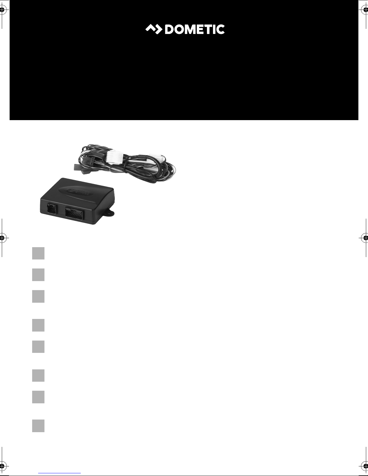
3Scope of delivery
No. in
fig. 4,
page 4
1 1 Electronic module
2 1 Cable set
3 1 Clutch switch
4 1 Fastening plate
Quantity Designation
12
Page 13
EN
MS880 Accessories
No. in
fig. 4,
page 4
5 1 Double-sided adhesive tape
6 1 Cable duct
7 10 Cable binders
8 2 Fastening screw
9 1 3 A fuse
Quantity Designation
For the system to function correctly, you will also require:
• a control element (see chapter “Accessories” on page 13)
• a vehicle-specific cable set (see www.dometic.eu/ms880)
• if applicable, a CAN bus interface (see chapter “Connection options” on
page 14)
4Accessories
Available as accessory (not included in scope of delivery):
Designation Ref. no.
Control lever MS-BE7 9600000387
CAN bus interface CBI150 9600000428
Vehicle-specific cable sets
–
(see www.dometic.eu/ms880)
5 Intended use
MagicSpeed MS880 (ref. no. 9600000382) can be used as a cruise control.
MagicSpeed is designed as an aid for drivers; it does not relieve you of the duty
to take proper care when driving.
MagicSpeed is designed for installation in cars, caravans and vans.
13
Page 14
EN
Technical description MS880
6 Technical description
6.1 Function description
When used as a cruise control, MagicSpeed MS880 keeps the preset speed of your
choice as constant as possible. The system compares the actual speed to the set
speed and corrects the actual speed as necessary.
The activation speed of the cruise control is about 40 km/h.
MagicSpeed is comprised of an electronic module and a cable set. The electronic
module is connected to a control element (accessory) with which you can make the
required settings. The control element is fitted in the dashboard area.
The system is equipped with various safety features for your protection.
6.2 Connection options
MagicSpeed MS880 can process either a digital speed signal from the CAN bus
(CAN bus connection) or an analogue speed signal (analogue connection). A CAN
bus connection is not possible in all vehicles with a CAN bus.
NOTE for vehicles with CAN bus
I
• You can find out whether a CAN bus connection is possible for your
vehicle from the vehicle-specific product overview on our homepage, or by calling to enquire (see rear page of the manual for
contact data).
• If your vehicle features a CAN bus, but a CAN bus connection is not
possible according to the vehicle list, MagicSpeed MS880 must be
connected using a analogue connector. This will require the speed
signal to be received in analogue form.
If the speed signal is only available on the CAN bus in digital form,
you will require the CAN bus interface MagicSpeed CBI150 for the
installation of MagicSpeed MS880. This converts the digital speed
signal from the CAN bus into an analogue one.
• A CAN bus interface is not required for the CAN bus connection.
14
Page 15
EN
MS880 Technical description
6.3 Safety features
NOTICE!
A
The cruise control is equipped with numerous safety features to switch it off if any of
the following situations arise:
• The brake is applied hard
• Pressing the clutch pedal
• Pressing the accelerator and brake pedal at the same time (savior function)
• The ON/OFF button on the control element is pressed
• The engine overspeeds
• Braking to 50 % of the set speed
• Accelerating to 150 % of the set speed
If your vehicle has a steering wheel lock, make sure that it is not activated
when the key is in the ignition or a gear is selected.
• Increases the engine speed by 150 %
• Decreases the engine speed by 75 %
• The ignition is switched off
NOTE
I
The cruise control also switches off if there are problems with the brake lights, such
as:
• Defective brake lights
• A defective fuse
• A loose connection to the brake light switch
In an emergency (e.g. accelerator sticks), you can use the savior function. It is
activated by pressing the accelerator and the brake pedal at the same time. It is
deactivated when the brake pedal is released. The savior function switches the
accelerator to idle electronically, it does not apply the brake. Therefore, keep the
brake pedal pressed down until the vehicle stops.
If MagicSpeed ever fails to react to one of these occurrences, you can
always switch off the ignition.
To guarantee safe and economical operation, never use the cruise control in
congested traffic or on wet, slippery roads.
15
Page 16

EN
Installing MagicSpeed MS880
7 Installing MagicSpeed
NOTE
I
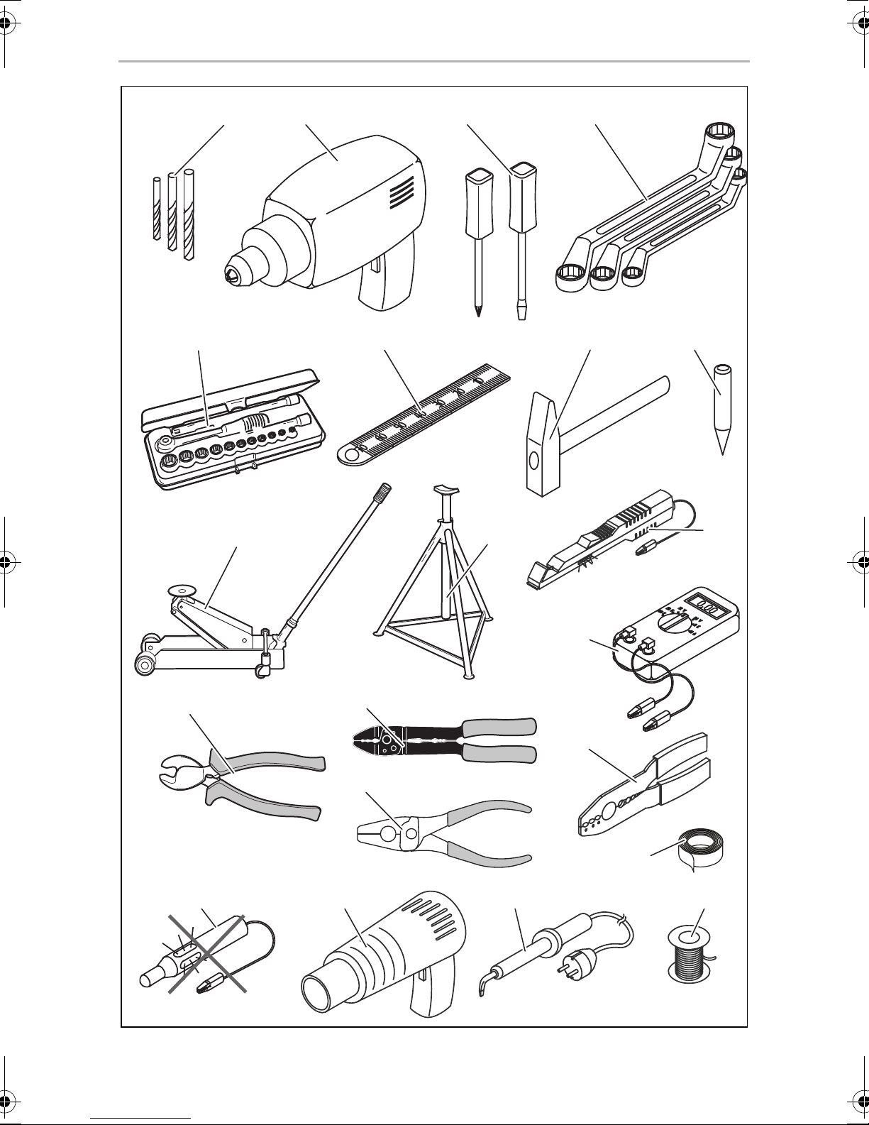
7.1 Tools required
For installation and assembly and the electrical connection, you will need the
following tools fig. 1, page 3.
To fasten the module and the cables, you may need additional screws and cable
binders.
7.2 Installing the electronic module
If you do not have sufficient technical knowledge for installing and
connecting the components in vehicles, you should have a specialist
install the system in your vehicle.
NOTE
I
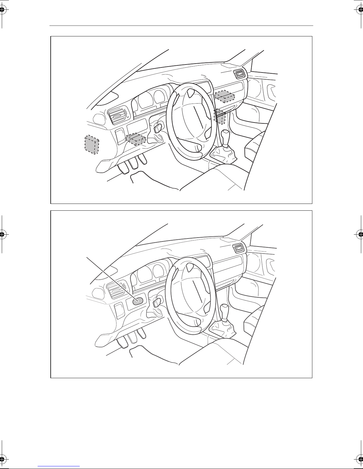
• Install the electronic module
– behind the glove compartment
– behind the footwell on the driver or passenger side
– under the dashboard on the driver side
– not anywhere subject to heat or moisture
– not in the engine compartment
– not near high-voltage components
– not directly next to ventilator nozzles.
• Where possible, use existing holes in the vehicle.
A
➤ Select a suitable installation location (fig. 5, page 5).
When selecting the installation location, observe the following
instructions:
NOTICE!
Before drilling holes, make sure the drill bit will not damage anything on
the other side (fig. 2, page 4).
Do not fasten the electronic module before you have decided where to lay the
cables.
➤ After finishing assembly, fasten the module to the selected position:
screw the electronic module securely to the vehicle with the screws supplied or
use double-sided adhesive tape.
16
Page 17

EN
MS880 Installing MagicSpeed
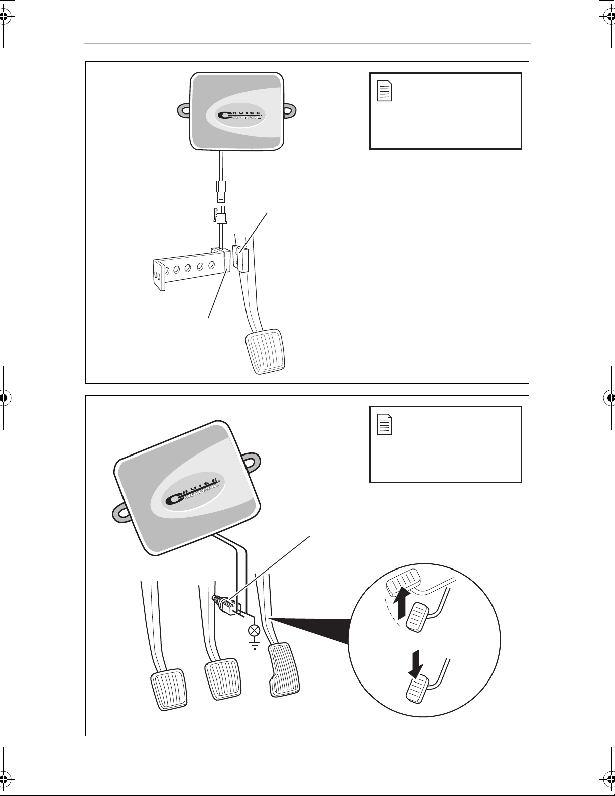
7.3 Installing the clutch switch
NOTE
I
Install the clutch switch as follows (fig. 8, page 7):
➤ Fasten the magnet (fig. 8 1, page 7) to the clutch pedal using double-sided
adhesive tape or cable binders.
➤ Fasten the clutch switch (fig. 8 2, page 7) in the footwell using the screws
supplied or double-sided adhesive tape.
➤ Connect the 2-pole clutch switch compact plug (fig. 8 2, page 7) with the
2-pole compact plug on the cruise control cable set.
I
Check whether your vehicle features a clutch switch. If it does, you do
not have to install the clutch switch supplied.
NOTE
On vehicles with manual transmission, you can use the clutch switch to
prevent engine overspeed. The cruise control switches off automatically
when you press down the clutch.
17
Page 18
EN
Connecting the electrical power to MagicSpeed MS880
8 Connecting the electrical power to
MagicSpeed
8.1 Laying and connecting the cable set
Please note the following:
• To prevent damage to the cables when laying them, ensure that they are far
enough away from hot or moving vehicle components (exhaust pipes, drive
shafts, light systems, fans, heater etc.).
• Wrap insulating tape around every connection on the cable (even inside the
vehicle).
• When laying the cables, make sure:
– they are not kinked or twisted
– they do not rub on edges
– they are not laid in sharp-edged ducts without protection (fig. 3, page 4).
• Protect every hole you drill against water penetration, e.g. by using a cable with
a sealant and by spraying the cable and the the cable sleeve with sealant.
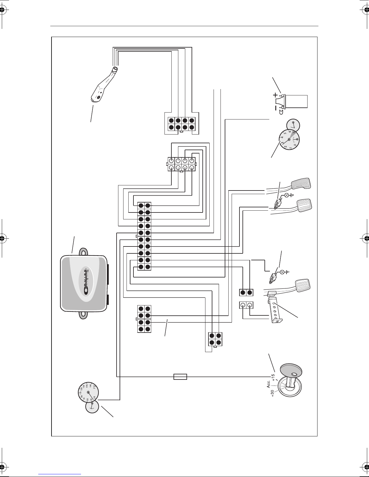
You will find a summary of the wiring in fig. 7, page 6.
No. Component
1 Electronic module
2 Control element
3 Ignition coil
4 Engine speed signal
5 Brake light switch
6 Original clutch switch
7Clutch switch
8 Ignition
9 Travel speed signal
10 Vehicle-specific cable set (not included)
18
Page 19
EN
MS880 Connecting the electrical power to MagicSpeed
Orange
NOTICE!
Make sure the ignition is switched off. Otherwise a fuse may blow.
A
➤ Connect the orange cable to a connected positive terminal (terminal 15).
➤ Use a voltmeter to check whether the selected positive terminal carries the full
operating voltage of 12 V and that the orange cable carries no voltage when the
ignition is off.
This test is usually done at the fuse box.
NOTICE!
A
Green
Do not connect the orange cable to the voltage supply for the vehicle
accessories (ACC).
➤ Insulate the green cable.
This cable is not needed. The required earth signal is taken from the accelerator
cable set.
Green/white and violet
NOTE
I
Alternatively, you can connect the purple cable with:
• a clutch switch
• the control lamp for the activated parking brake
• (automatic transmission only): the control lamp for park or neutral
You can connect the clutch switch supplied or the vehicle's original clutch switch (if
available) to the green/white and purple cable.
With a CAN bus connection, these cables are only connected when
there is no clutch signal on the CAN bus in your vehicle. See also the
information in the vehicle-specific product overview at
www.dometic.eu/ms880.
Using the clutch switch supplied
➤ Install the clutch switch as described in chapter “Installing the clutch switch” on
page 17.
19
Page 20
EN
Connecting the electrical power to MagicSpeed MS880
Using the original clutch switch
➤ Cut off the two-pin plug from the green/white and purple cable.
➤ Connect the purple cable with the original clutch switch cable, whose signals
change when you apply the clutch pedal.
The purple cable can process the following changes:
– Connect to earth
– From earth to ∞
– From earth to +12 V
– From +12 V to earth
➤ Insulate the green/white cable.
This cable is not required when using an original clutch switch.
Twisted cable pair (blue and blue/white)
NOTE
I
• Both these cables are only connected when there is a CAN bus
connection.
They are not required for analogue connection. In this case, insulate
the ends and store them.
• Do not mix up the cables. Otherwise the cruise control will not
function.
➤ Connect the blue cable (P3) to CAN high.
➤ Connect the blue/white cable (P2) to CAN low.
NOTE
I
For a CAN bus connection, all cables in the cable set are now
connected. You can now install the control element, see chapter “Installing the control element (accessory)” on page 25.
In this case, insulate the ends of the remaining four cables and store
them.
20
Page 21
EN
MS880 Connecting the electrical power to MagicSpeed
Brown and brown/white
NOTE
I
➤ Connect the brown cable and the brown/white cable to the brake light switch
(fig. 9 1, page 7).
If there are more than two cables leading from the brake light switch, this is how to
identify the two cables you need:
➤ Use a voltmeter to measure the voltage on the cables.
One of the two original cables on the brake light switch should have a
permanent positive voltage (terminal 30, 12 V) or a connected positive voltage
(terminal 15).
Both these cables must only be connected when there is an analogue
connection.
They are not required for the CAN bus connection. In this case, insulate
the ends and store them.
The second original cable should have a voltage of +12 V when the brake is
applied. As soon as the brake pedal is released, no more voltage should be on
that cable.
If you cannot measure a full +12 V on the brake light switch, you vehicle probably has
a digital brake system.
In this case, connect the two cables as follows:
➤ Connect the brown/white cable to a fuse-protected, connected positive
terminal (terminal 15).
➤ Connect the brown cable to the original cable leading to the brake lights.
The voltage on this cable is +12 V with the brake applied, and 0 V with the brake
released. You will find these cables directly at the rear lights or in the wiring
harness at the rear of the vehicle.
21
Page 22
EN
Connecting the electrical power to MagicSpeed MS880
Yellow and blue
NOTE
I
The yellow cable and the blue cable are for connection to the travel speed and
engine speed signals respectively:
• Blue:
Records the engine or travel speed signal with a voltage between 1.5 V and 24 V
and a frequency between 6 Hz and 8.5 kHz.
Use the blue cable for speed signals whose voltage and frequency are within
above-mentioned ranges.
• Yellow:
Records the engine speed signals with a voltage between 6 V and 250 V and a
frequency between 6 Hz and 488 Hz.
Both these cables are only connected when there is an analogue
connection.
They are not required for the CAN bus connection. In this case, insulate
the ends and store them.
Use the yellow cable to record engine speed signals with a voltage of more than
20 V or when engine overspeed protection is required.
NOTE
The signal input depends on the vehicle's transmission.
I
When connecting the blue and yellow cables, there are various parameters to take
into account, which are described in the following sections:
• Which signal input do you wish to use (page 23)?
• Do you need engine overspeed protection (page 23)?
• Does your vehicle have automatic transmission (page 24)?
• Does your vehicle have manual transmission (page 24)?
• Where do you wish to record the speed ( Diagnostic manual)?
• Where do you wish to record the engine speed ( Diagnostic manual)?
• What are the voltage and frequency of the signal ( Diagnostic manual)?
NOTE
You can find a diagnostics manual on our homepage.
I
22
Page 23
EN
MS880 Connecting the electrical power to MagicSpeed
Selecting the signal input
There are two ways to record a reference signal for the cruise control:
• Speed signal
The travel speed signal indicates the actual travel speed.
The travel speed signal must be used for vehicles with automatic transmission.
If you use the travel speed signal for vehicles with manual transmission, you must
install a deactivation system to prevent engine overspeed (see chapter “Using
engine overspeed protection” on page 23).
• Engine speed signal (rpm)
The engine speed signal indicates the engine speed in rpm.
The cruise control can identify the travel speed using the engine speed as long
as you do not shift gear.
The engine speed signal is only suitable for vehicles with manual transmission.
You must install a switch-off system to prevent engine overspeed (see chapter
“Using engine overspeed protection” on page 23).
Using engine overspeed protection
NOTICE!
A
If a travel speed signal is used as a signal source on vehicles with manual
transmission, there must be an engine overspeed protection system in order to
prevent damage to the engine.
If you press the clutch while the cruise control is activated, the cruise control must
automatically switch off as the engine may otherwise be damaged.
There are two types of engine overspeed protection system:
• If you use the blue cable to transmit the speed signal, you can connect the yellow
cable to transmit the engine speed and therefore ensure the engine is protected.
• If there is no engine speed signal, you can use the clutch switch. Install the clutch
switch on the clutch pedal (fig. 8 1, page 7) so that the cruise control switches
off automatically when the clutch pedal is pressed.
On vehicles with manual transmission, an engine overspeed protection
must be installed.
23
Page 24
EN
Connecting the electrical power to MagicSpeed MS880
Vehicles with automatic transmission
NOTICE!
A
No additional overspeed protection is required for vehicles with automatic
transmission.
➤ Connect the blue cable to transmit the speed signal.
Vehicles with manual transmission
➤ Connect the blue cable to the travel speed signal.
➤ Connect the yellow cable as overspeed protection using the engine speed
signal or the clutch switch.
Never use an engine speed signal. Otherwise the system will not switch
off when the transmission declutches. The engine could overrun and be
damaged!
Alternatively, you can:
• Connect the blue cable to the engine speed signal, or
• Connect the yellow cable to the negative terminal end of the ignition coil
(terminal 1).
With this solution, no additional overspeed protection is required because the
engine speed is monitored by the speed regulator. If you use the engine speed
signal, the activation speed of the speed regulator depends on the gear the vehicle
is currently in.
8.2 Connecting the vehicle-specific cable set
You must connect the electronic module to the accelerator pedal using a
vehicle-specific cable set (not supplied).
NOTICE! Risk of damage!
A
Do not connect the green cable of the main wiring harness to the earth.
The earth connection is made via the accelerator cable set.
➤ Cut the the original connection of the accelerator pedal.
➤ Connect one end of the vehicle-specific cable set to the accelerator pedal.
➤ Connect the other end of the vehicle-specific cable set to the loose end of the
original connection.
➤ Insert the 8-pin plug into the appropriate socket on the electronic module.
24
Page 25

EN
MS880 Installing the control element (accessory)
9 Installing the control element
(accessory)
➤ Read the instructions enclosed with your control element carefully before
assembly.
10 Setting procedure
The procedure remaining after installation and connection depends on the type of
connection.
For CAN bus connections (connection to the CAN bus) you must perform the
following steps:
• To synchronise the system for CAN bus connection,
see chapter “Synchronising with a CAN-bus connection” on page 27
• To check the system connection, see chapter “Testing MagicSpeed (diagnosis
mode)” on page 32
• To test the system: see chapter “Testing functions” on page 38
For analogue connections (analogue speed signal) you must perform the
following steps:
• To synchronise the system for analogue connection,
see chapter “Synchronising with an analogue connection” on page 30
• Perform pedal test,
see chapter “Adjusting the accelerator pedal manually” on page 31
• To check the system connection, see chapter “Testing MagicSpeed (diagnosis
mode)” on page 32
• Start automatic mode,
see chapter “Starting automatic mode” on page 35
• Set the control sensitivity (if necessary),
see “Setting the control sensitivity (GAIN mode)” in the diagnostics manual on
our homepage
• To test the system: see chapter “Testing functions” on page 38
25
Page 26
EN
Setting procedure MS880
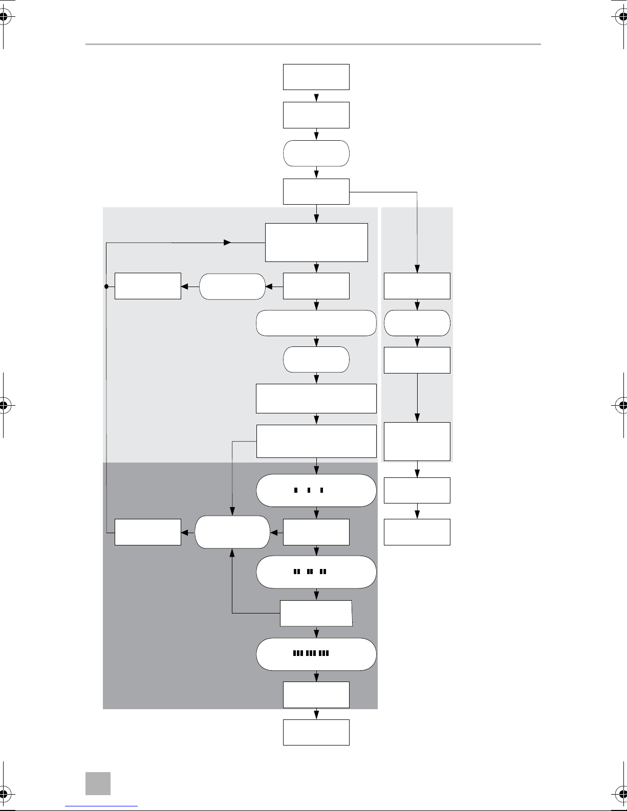
Setup Mode
Quitting setup mode: Press and hold down the brake pedal; press the SET button four times (you will hear one long beep)
STANDARD OPERATION
• Ignition ON
• Press ON/OFF button on the control module
• Press and hold down the brake pedal
• Press the SET button four times
•
Press and hold down the brake pedal
•
Press the SET button once
•
Release the brake pedal
•
Press and hold down the brake pedal
•
Press the SET button twice
•
Release the brake pedal
•
Press and hold down the brake pedal
•
Press the SET button three times
•
Release the brake pedal
(1 high
beep)
1 beep/counter value
Continuous
beep
Low beeps
High or low
+ high beeps
1 beep/counter value
No
Yes
Press “SET”
Press “RES”
Brake?
Not
OK
OK
Throttle pedal setup
Quit throttle pedal setup
and save the setting
Program
Pedal test
Press and
release pedal
Idle position
Full throttle
position
(2 high
beeps)
Press “SET”
Manual PPM
Quit manual PPM
and save the setting
Drive car at
a convenient speed
PPM value
Brake?
Press “SET”
n high beeps/counter value n low beeps/counter value
Press “RES”
No
Increase
Decrease
Yes
•
Press and hold down the brake pedal
•
Press the SET button four times
•
Release the brake pedal
(4 high
beeps)
Quit manual GAIN
and save the setting
Drive car at
a convenient speed
Brake?
Press “SET”
n high beeps/counter value n low beeps/counter value
Press “RES”
No
Increase
Decrease
Yes
Manual GAIN
GAIN value
Press “SET”
(3 high
beeps)
Press “SET”
Manual INIT
Quit manual INIT
and save the setting
Drive car at
a convenient speed
INIT value
Brake?
Press “SET”
n high beeps/counter value n low beeps/counter value
Press “RES”
No
Increase
Decrease
Yes
26
Page 27

EN
MS880 Synchronising with a CAN-bus connection
11 Synchronising with a CAN-bus
connection
Step 1 (synchronisation)
➤ Press and hold the SW1 button on the rear of the electronic module.
➤ Switch on the ignition.
✓ You will hear two high-pitched signals.
➤ Let go of the SW1 button.
➤ Manual transmission: Apply the brake and clutch pedal and keep both
pressed down.
➤ Automatic transmission: Apply the brake pedal and hold it down. Put the gear
into neutral.
➤ Press the SET button on the control element.
✓ The LED on the electronic module starts flashing.
✓ The electronics start to synchronise with the vehicle automatically.
✓ When the synchronisation is complete, you will hear three high-pitched signals.
✓ The LED on the electronic module lights up permanently.
➤ Manual transmission: Remove your foot from the brake and the clutch pedal.
➤ Automatic transmission: Remove your foot from the brake pedal and put the
gear into neutral.
NOTE
I
✓ After successful synchronisation, the electronics automatically continue with
step 2 (pedal test).
If you do not hear three high-pitched signals, check the connections
to CAN high (blue cable) and CAN low (blue/white cable) and check
whether MagicSpeed MS880 can be connected to the CAN bus in your
vehicle according to the vehicle list.
27
Page 28
EN
Synchronising with a CAN-bus connection MS880
…
…
…
Step 2 (accelerator pedal test)
➤ Press the accelerator pedal slowly as far as it will go and let it return the same way
slowly as far as the neutral position.
✓ While this happens,you will hear acoustic signals which signify the various
positions:
– Neutral position (idle):
–50% position:
–100% position:
NOTE
I
• If a low-pitched signal does not sound or you hear a high-pitched
signal during the pedal test, this step has failed and programming
must be repeated from step 1.
• Some accelerator pedals do not provide sufficient electric signals
when fully pressed down. In this case, only press the pedal approx.
three-quarters of the way down in step 2, as otherwise the test will
not be successful.
Step 3 (quit synchronisation)
➤ Switch the ignition off.
✓ Normally, your cruise control should be ideally preset for your vehicle.
Refer to the figure on page 29 for a summary of the CAN bus connection and pedal
test.
28
Page 29
EN
MS880 Synchronising with a CAN-bus connection
Press and hold down
the SW1 button
Ignition ON
2 beeps
Step 1:
synchronisation
CAN bus search
unsuccessful
Step 2:
pedal test begins
1 long beep
Release the
SW1 button
CAN Bus
MT: Press the brake and
clutch pedals and hold down
AT: press and hold down
the brake pedal + neutral position
Press the
SET button
Electronic module LED flashes:
CAN bus search in progress
3 beeps
Electronic module LED is lit up constantly:
CAN bus search successful
MT: release brake and clutch pedal
AT: release brake pedal + park position
Sound sequence:
Neutral position of gas pedal detected
…
Analog
Press the
RES button
4 beeps
System
is reset
System for
analog connection
configured
Ignition OFF
Pedal test
unsuccessful
MT: manual transmission
AT: automatic transmission
high/low-pitched
Continuous
beeps
Press accelerator
pedal 50%
Sound sequence:
50% position detected
Press down accelerator
all the way (100%)
Sound sequence:
100% position detected
…
…
Pedal test
successful
Ignition OFF
Continue with
setup mode
29
Page 30
EN
Synchronising with an analogue connection MS880
12 Synchronising with an analogue
connection
NOTE
I
12.1 Switching MagicSpeed to analogue connection
➤ Press and hold the SW1 button on the rear of the electronic module.
➤ Switch on the ignition.
✓ You will hear two high-pitched signals.
➤ Let go of the SW1 button.
➤ Press the RES button on the control element.
Before you can configure the settings, you must switch the system to
analogue connection.
✓ The electronic module is switched from the “CAN bus connection” setting to the
“Analogue connection” setting.
✓ When the switchover is complete, you will hear four high-pitched signals.
➤ Switch the ignition off.
12.2 Starting setup mode
NOTE
I
To start setup mode, proceed as follows:
➤ Depending on the mode, do one of the following:
– For automatic mode: start the motor.
– For the other modes: switch the ignition off and on again.
• To begin one of the adjusting and teach modes you must always
carry out the following procedure.
• For automatic mode (page 35), you first have to start the motor.
• For any of the other modes, you first simply have to switch the
ignition off and on again.
➤ Press the ON/OFF button on the control element.
➤ Apply the brake within one minute and hold it down.
➤ Press the setup button four times in rapid succession.
30
Page 31

EN
MS880 Synchronising with an analogue connection
➤ Release the brake.
✓ You will hear four acoustic signals.
✓ You are now in setup mode and can set the cruise control.
12.3 Adjusting the accelerator pedal manually
In this mode, the accelerator pedal parameters are taught to the electronic module
manually.
NOTE
I
• After each programming step is successfully completed, it is
confirmed by an intermittent tone of the same pitch. If there is an
intermittent tone of differing pitch, this step has failed and the
programming must be repeated from step 1.
• Some accelerator pedals do not provide sufficient electric signals
when fully pressed down. In this case, only press the pedal approx.
three-quarters of the way down, as otherwise programming will not
be successful.
Step 1
➤ Start setup mode (chapter “Starting setup mode” on page 30).
➤ Apply the brake and hold it down.
➤ Press the RES button once.
✓ An low-pitched acoustic signal sounds.
➤ Release the brake.
Step 2
➤ In neutral position (accelerator pedal is not pressed down), press the SET-button
once.
✓ The idling value is programmed.
Step 3
➤ Press the accelerator pedal down as far as it will go and press the RES button
once.
31
Page 32

EN
Synchronising with an analogue connection MS880
Step 4
➤ Press the accelerator pedal slowly as far as it will go and let it return the same way
slowly as far as the neutral position.
✓ A constant signal sounds during this procedure.
Step 5
When steps 1 to 4 have been successfully completed:
➤ Activate the brake.
✓ The set values are stored permanently in the electronic module.
✓ Teach mode will be exited.
12.4 Testing MagicSpeed (diagnosis mode)
The cruise control has a self-diagnosis mode. The self-diagnosis mode is divided into
three sections (modes A, B and C) and tests all components and functions of the
cruise control.
➤ Before you start self-diagnosis, check again that all the cables are correctly
connected.
➤ Apply the handbrake.
➤ Shift the gear to neutral, or to neutral or park if it is automatic.
➤ Press down the SET button on the control element and hold it.
➤ Switch on the ignition.
✓ An audible signal sounds as long as you hold the SET button.
➤ Let go of the SET button.
✓ The audible signal stops.
If you hear another signal within a second of letting go of the SET button, a
control input is activated, for example the clutch switch.
➤ Check the cable connections to find the control input.
32
Page 33

EN
MS880 Synchronising with an analogue connection
NOTE
I
Diagnosis mode A
Diagnosis mode A tests the electronic components and electrical connections.
The LED in the electronic module and the integrated buzzer simultaneously show
that the electric wiring and the components are working properly. When checking
the components later, it is not necessary to uncover the electronic module, because
the audible signals accompany the optical ones.
You will receive confirmation from the LEDs and the buzzer when you activate the
following signals:
The diagnosis modes are for testing all components and functions of the
cruise control. The cruise control uses an internally generated reference
signal to test the electric module in diagnosis mode B.
If the cruise control does not work after diagnosis mode B is completed,
there is generally a problem recording the travel speed signal.
• SET button
• RES button
• Brake
• Clutch switch
• Neutral safety switch
• Travel speed signal in teach mode
• Engine speed signal in teach mode
The audible and visible signals are emitted for a maximum of ten seconds per input
to ensure that other messages are not suppressed.
If you activate one of the functions above and do not hear or see a signal:
➤ Check the electric wiring.
33
Page 34

EN
Synchronising with an analogue connection MS880
Diagnosis mode B
Diagnosis mode B tests the function of the accelerator.
➤ Apply the handbrake.
➤ Shift the gear to neutral, or to neutral or park if it is automatic.
➤ Press and hold down the SET button.
➤ Start the engine.
➤ When the engine is running, let go of the SET button.
➤ Now switch on the speed controller using the ON/OFF button on the control
element.
✓ The LED in the control element lights up.
NOTICE!
Do not let the engine overrun.
A
➤ To increase the engine speed press and hold down the SET button.
✓ The engine speed slowly increases.
➤ To reduce the engine speed press and hold down the RES button.
✓ The engine speed slowly drops.
➤ To drop the engine speed back down to the idle speed again,
– apply the brake or clutch, or
– press the ON/OFF button on the control element.
➤ To quit diagnosis mode, switch off the ignition.
NOTE
I
For safety reasons, the engine speed can only be increased by 66 % of
the maximum value.
34
Page 35

EN
MS880 Synchronising with an analogue connection
Diagnosis mode C
Diagnosis mode C tests the travel speed or engine speed signal.
➤ Press and hold down the SET button.
➤ Start the engine.
➤ When the engine is running, let go of the SET button.
➤ Drive your vehicle at a speed of around 50 km/h.
➤ Now switch on the cruise control using the ON/OFF button on the control
element.
✓ The LED in the electronic module flashes and an audible signal sounds once per
second.
➤ Bring the vehicle to a stop.
➤ Switch the ignition off.
✓ The diagnosis mode has been quit.
12.5 Starting automatic mode
In automatic mode, the PPM and GAIN parameters are automatically synchronised
with your vehicle. You can still fine-tune both parameters anytime.
➤ Start setup mode (chapter “Starting setup mode” on page 30).
➤ Apply the brake and hold it down.
➤ Press the RES button twice.
✓ You will hear two low-pitched signals.
➤ Release the brake.
✓ You will hear two high-pitched signals.
NOTE
If you hear more than two signals, repeat the procedure.
I
➤ Drive the vehicle at a speed of 70 km/h to allow the PPM and GAIN parameters
to be set automatically.
➤ Press the SET button.
✓ The cruise control switches itself on.
35
Page 36

EN
Synchronising with an analogue connection MS880
If the cruise control does not take on the speed gently or the save value is not
applied:
➤ Press the SET button again to increase the value or
➤ ... press the RES button to decrease the value.
✓ You will hear a signal each time you press the button.
The current value is indicated by the number of beeps (3 – 14 beeps). The factory
setting is 5 beeps.
➤ Apply the brake to save the set values (PPM and GAIN).
✓ Normally, your cruise control should be ideally preset for your vehicle.
➤ Quit setup mode (chapter “Quitting setup mode” on page 36).
➤ You can now use MagicSpeed MS880.
NOTE
I
If, during operation, you notice that the vehicle reacts too slowly or too
suddenly, or the speed is not being regulated correctly, you must set the
control sensitivity manually (see “Setting the control sensitivity (GAIN
mode)” in the diagnostics manual on our homepage).
12.6 Quitting setup mode
To quit setup mode, proceed as follows:
➤ Stop the vehicle.
➤ Apply the brake and hold it down.
➤ Press the SET button four times.
✓ You will hear a long signal.
✓ You have now quit setup mode.
36
Page 37

EN
MS880 Self-diagnosis program
13 Self-diagnosis program
MagicSpeed MS880 has a self-diagnosis program. After activation in driving mode,
the cruise control or the speed limiter (variable) deactivates itself automatically if
there is a fault. In this case, the cause of the fault is indicated by a series of highpitched beeps.
The cruise control or speed limiter switches off:
• if one of the control element buttons is jammed or held down for longer than
20 s. There is one high-pitched beep.
• if the current speed increases unusually (> 9 km/h per second). There are two
high-pitched beeps.
• if the current speed is less than 33 km/h. There are three high-pitched beeps.
• if the current speed is more than 250 km/h. There are four high-pitched beeps.
• if the current speed falls below 75 % of the stored speed (e.g. going uphill).
There are five high-pitched beeps.
• if the current speed increases to over 150 % of the stored speed (e.g. going
downhill). There are six high-pitched beeps.
• if there is a fault in the accelerator pedal cable set. There are seven high-pitched
beeps.
• if the engine speed increases unusually. There are eight high-pitched beeps.
NOTE
I
You can find a diagnostics manual on our homepage.
(www.dometic.eu/ms880)
37
Page 38

EN
Testing functions MS880
14 Testing functions
14.1 Testing the cruise control function
NOTE
The lowest speed at which the cruise control works is around 40 km/h.
I
➤ Start the vehicle.
➤ Switch on the cruise control by pressing the ON/OFF button on the control
element briefly (<1sec).
✓ You will hear two low-pitched signals.
✓ The LED on the control element lights up in green.
➤ Drive at a speed of 40 to 50 km/h.
➤ Press the SET button to configure the preferred speed.
✓ The cruise control gently takes on the speed and maintains the driving speed at a
constant level.
14.2 Setting the sensitivity
If the cruise control does not switch on gently and the speed increases or decreases
during control mode, you can adjust the sensitivity of the cruise control (see
page 30):
• If the cruise control works too suddenly or the vehicle speeds up too much, you
must decrease the GAIN value (see “Setting the control sensitivity (GAIN mode)”
in the diagnostics manual on our homepage).
• If the cruise control works too slowly or the vehicle slows down too much, you
must increase the GAIN value (see “Setting the control sensitivity (GAIN mode)”
in the diagnostics manual on our homepage).
38
Page 39

EN
MS880 Using MagicSpeed
15 Using MagicSpeed
MagicSpeed is controlled using the buttons on the control lever.
15.1 Using the cruise control
ON/OFF button
➤ Press the ON/OFF button once briefly (< 1 sec) to switch on the cruise control.
✓ You will hear two low-pitched signals.
✓ The LED on the control element lights up.
➤ Press the ON/OFF button again to switch the cruise control off.
✓ The LED on the control element goes out.
SET button
Use the SET button to save a preferred speed in the cruise control.
➤ Press the SET button and let go again immediately to set the speed you are
currently driving.
This set speed is maintained until:
– you apply the brake or clutch pedal,
– you switch off the device with the ON/OFF button,
– the vehicle slows down to below the lower activation speed,
– the speed drops by more than 25 % on a slope.
➤ Press the SET button continuously to accelerate the vehicle.
When you let go of the SET button, the cruise control records the current speed
and saves it.
RES button
Press the RES button to recall the last saved speed when:
• you have switched on the cruise control using the ON/OFF button,
• you do not apply the brake or clutch pedal,
• you do not switch off the ignition in the meantime,
• the vehicle does not slow down to below the lower activation speed,
• the current speed is not less than 50 % of the saved value.
➤ Press the RES button and let go again immediately to recall the last saved speed.
39
Page 40

EN
Using MagicSpeed MS880
Accelerating and decelerating
If the cruise control is activated, you have the option of fine tuning it.
This allows you to adapt the speed of the vehicle precisely to suit traffic conditions or
speed limits.
➤ Touch the SET button to increase the speed by 1.5 km/h.
➤ Press the SET button for 1 second to increase the speed by 10 km/h.
➤ Touch the RES button to decrease the speed by 1.5 km/h.
➤ Press the RES button for 1 second to reduce the speed by 10 km/h.
If, for example, you wish to increase the speed by around 5 km/h, touch the SET
button three times.
NOTE
I
If you wish to decrease the set speed sharply, do not use the RES button.
Use the ON/OFF button, the brake or the clutch and then press the SET
button to set the speed you prefer.
15.2 Resetting the software
➤ Press and hold the SW1 button on the rear of the electronic module.
➤ Switch on the ignition.
✓ You will hear two high-pitched signals.
➤ Let go of the SW1 button.
➤ Press the SET button on the control element.
✓ The LED on the electronic module starts flashing.
✓ The electronics start to synchronise with the vehicle automatically and reset the
software to its status when delivered.
✓ After the software is successfully reset, you will hear three signals.
➤ Switch the ignition off.
40
Page 41

EN
MS880 Maintaining and cleaning MagicSpeed
16 Maintaining and cleaning MagicSpeed
NOTICE!
A
➤ Clean the components with a damp cloth from time to time.
Do not use sharp or hard objects to clean the device as these may
damage the device.
17 Troubleshooting
NOTE
You can find a diagnostics manual on our homepage.
I
18 Guarantee
The statutory warranty period applies. If the product is defective, please contact the
manufacturer's branch in your country (see the back of the instruction manual for the
addresses) or your retailer.
For repair and guarantee processing, please send the following items:
• Defect components
• A copy of the receipt with purchasing date
• A reason for the claim or description of the fault
19 Disposal
➤ Place the packaging material in the appropriate recycling waste bins wherever
possible.
If you wish to finally dispose of the product, ask your local recycling centre
or specialist dealer for details about how to do this in accordance with the
M
applicable disposal regulations.
41
Page 42

EN
Technical data MS880
20 Technical data
MagicSpeed MS880
Reference number: 9600000382
Operating voltage: 12 Vg
Current consumption: max. 10.5 A
Operating temperature: –40 °C to +85 °C
Certifications:
24
10R 04 1274
42
Page 43

DE
MS880
Bitte lesen Sie diese Anleitung vor Einbau und Inbetriebnahme sorgfältig
durch und bewahren Sie sie auf. Geben Sie sie im Falle einer Weitergabe
des Produktes an den Nutzer weiter.
Inhaltsverzeichnis
1 Hinweise zur Benutzung der Anleitung . . . . . . . . . . . . . . . . . . . . . . . . . . . . 44
2 Sicherheits- und Einbauhinweise . . . . . . . . . . . . . . . . . . . . . . . . . . . . . . . . . 44
3 Lieferumfang . . . . . . . . . . . . . . . . . . . . . . . . . . . . . . . . . . . . . . . . . . . . . . . . . 47
4 Zubehör. . . . . . . . . . . . . . . . . . . . . . . . . . . . . . . . . . . . . . . . . . . . . . . . . . . . . 47
5 Bestimmungsgemäßer Gebrauch . . . . . . . . . . . . . . . . . . . . . . . . . . . . . . . . 48
6 Technische Beschreibung . . . . . . . . . . . . . . . . . . . . . . . . . . . . . . . . . . . . . . 48
7 MagicSpeed montieren . . . . . . . . . . . . . . . . . . . . . . . . . . . . . . . . . . . . . . . . 50
8 MagicSpeed elektrisch anschließen . . . . . . . . . . . . . . . . . . . . . . . . . . . . . . 52
9 Bedienelement montieren (Zubehör) . . . . . . . . . . . . . . . . . . . . . . . . . . . . . 60
10 Vorgehensweise beim Einstellen . . . . . . . . . . . . . . . . . . . . . . . . . . . . . . . . . 60
11 Synchronisieren bei CAN-Bus-Anbindung . . . . . . . . . . . . . . . . . . . . . . . . . 62
12 Synchronisieren bei analoger Anbindung. . . . . . . . . . . . . . . . . . . . . . . . . . 65
13 Selbstdiagnose-Programm. . . . . . . . . . . . . . . . . . . . . . . . . . . . . . . . . . . . . . 73
14 Funktionen testen . . . . . . . . . . . . . . . . . . . . . . . . . . . . . . . . . . . . . . . . . . . . . 74
15 MagicSpeed benutzen . . . . . . . . . . . . . . . . . . . . . . . . . . . . . . . . . . . . . . . . . 75
16 MagicSpeed pflegen und reinigen . . . . . . . . . . . . . . . . . . . . . . . . . . . . . . . 77
17 Fehler suchen . . . . . . . . . . . . . . . . . . . . . . . . . . . . . . . . . . . . . . . . . . . . . . . . 77
18 Gewährleistung. . . . . . . . . . . . . . . . . . . . . . . . . . . . . . . . . . . . . . . . . . . . . . . 78
19 Entsorgung . . . . . . . . . . . . . . . . . . . . . . . . . . . . . . . . . . . . . . . . . . . . . . . . . . 78
20 Technische Daten . . . . . . . . . . . . . . . . . . . . . . . . . . . . . . . . . . . . . . . . . . . . . 78
43
Page 44

DE
Hinweise zur Benutzung der Anleitung MS880
1 Hinweise zur Benutzung der Anleitung
WARNUNG!
!
A
Sicherheitshinweis: Nichtbeachtung kann zu Tod oder schwerer
Verletzung führen.
ACHTUNG!
Nichtbeachtung kann zu Materialschäden führen und die Funktion des
Produktes beeinträchtigen.
HINWEIS
Ergänzende Informationen zur Bedienung des Produktes.
I
2 Sicherheits- und Einbauhinweise
Der Hersteller übernimmt in folgenden Fällen keine Haftung für Schäden:
• Montage- oder Anschlussfehler
• Beschädigungen am Produkt durch mechanische Einflüsse und Über-
spannungen
• Veränderungen am Produkt ohne ausdrückliche Genehmigung vom Hersteller
• Verwendung für andere als die in der Anleitung beschriebenen Zwecke
Beachten Sie die vom Fahrzeughersteller und vom Kfz-Handwerk
vorgeschriebenen Sicherheitshinweise und Auflagen!
WARNUNG!
Unzureichende Leitungsverbindungen können zur Folge haben, dass
!
durch Kurzschluss
• Kabelbrände entstehen,
• der Airbag ausgelöst wird,
• elektronische Steuerungseinrichtungen beschädigt werden,
• elektrische Funktionen ausfallen (Blinker, Bremslicht, Hupe, Zündung,
Licht).
ACHTUNG!
Klemmen Sie wegen der Kurzschlussgefahr vor Arbeiten an der Fahrzeug-
A
44
elektrik immer den Minuspol ab.
Bei Fahrzeugen mit Zusatzbatterie müssen Sie an dieser ebenfalls den
Minuspol abklemmen.
Page 45

DE
MS880 Sicherheits- und Einbauhinweise
Beachten Sie deshalb folgende Hinweise:
• Verwenden Sie bei Arbeiten an den folgenden Leitungen nur isolierte Kabelschuhe, Stecker und Flachsteckhülsen:
– 30 (Eingang von Batterie Plus direkt)
– 15 (Geschaltetes Plus, hinter Batterie)
– 31 (Rückleitung ab Batterie, Masse)
– L (Blinkerleuchten links)
– R (Blinkerleuchten rechts)
Verwenden Sie keine Lüsterklemmen.
• Verwenden Sie eine Krimpzange zum Verbinden der Kabel.
• Schrauben Sie das Kabel bei Anschlüssen an Leitung 31 (Masse)
– mit Kabelschuh und Zahnscheibe an eine fahrzeugeigene Masseschraube
oder
– mit Kabelschuh und Blechschraube an das Karosserieblech.
Achten Sie auf eine gute Masseübertragung!
Beim Abklemmen des Minuspols der Batterie verlieren alle flüchtigen Speicher der
Komfortelektronik ihre gespeicherten Daten.
• Folgende Daten müssen Sie je nach Fahrzeugausstattung neu einstellen:
–Radiocode
–Fahrzeuguhr
– Zeitschaltuhr
– Bordcomputer
– Sitzposition
Hinweise zur Einstellung finden Sie in der jeweiligen Bedienungsanleitung.
Beachten Sie folgende Hinweise bei der Montage:
VORSICHT!
!
• Befestigen Sie die im Fahrzeug montierten Teile so, dass sie sich unter
keinen Umständen (scharfes Abbremsen, Verkehrsunfall) lösen und zu
Verletzungen der Fahrzeuginsassen führen können.
• Befestigen Sie verdeckt unter Verkleidungen anzubringende Teile des
Systems so, dass sie sich nicht lösen oder andere Teile und Leitungen
beschädigen und keine Fahrzeugfunktionen (Lenkung, Pedale usw.)
beeinträchtigen können.
• Beachten Sie immer die Sicherheitshinweise des Fahrzeugherstellers.
Einige Arbeiten (z. B. an Rückhaltesystemen wie Airbag usw.) dürfen
nur von geschultem Fachpersonal durchgeführt werden.
45
Page 46

DE
Sicherheits- und Einbauhinweise MS880
ACHTUNG!
A
Beachten Sie folgende Hinweise bei der Arbeit an elektrischen Teilen:
A
• Achten Sie beim Bohren auf ausreichenden Freiraum für den Bohrer-
austritt, um Schäden zu vermeiden.
• Entgraten Sie jede Bohrung und behandeln Sie diese mit Rostschutzmittel.
ACHTUNG!
• Benutzen Sie zum Prüfen der Spannung in elektrischen Leitungen nur
eine Diodenprüflampe oder ein Voltmeter.
Prüflampen mit einem Leuchtkörper nehmen zu hohe Ströme auf,
wodurch die Fahrzeugelektronik beschädigt werden kann.
• Beachten Sie beim Verlegen der elektrischen Anschlüsse, dass diese
– nicht geknickt oder verdreht werden,
– nicht an Kanten scheuern,
– nicht ohne Schutz durch scharfkantige Durchführungen verlegt
werden.
• Isolieren Sie alle Verbindungen und Anschlüsse.
• Sichern Sie die Kabel gegen mechanische Beanspruchung durch
Kabelbinder oder Isolierband, z. B. an vorhandenen Leitungen.
Beachten Sie insbesondere folgende Hinweise:
• Beachten Sie die geltenden gesetzlichen Vorschriften.
• Verhalten Sie sich beim Fahren so, dass eine Gefährdung anderer Verkehrs-
teilnehmer ausgeschlossen ist.
• MagicSpeed soll Sie zusätzlich unterstützen, d. h. das Gerät entbindet Sie nicht
von Ihrer besonderen Vorsichtspflicht beim Fahren.
46
Page 47

DE
MS880 Lieferumfang
3 Lieferumfang
Nr. in
Abb. 4,
Seite 4
1 1 Elektronikmodul
2 1 Kabelsatz
3 1 Kupplungsschalter
4 1 Befestigungsplatte
5 1 Doppelseitiges Klebeband
6 1 Kabeldurchführung
7 10 Kabelbinder
8 2 Befestigungsschraube
Menge Bezeichnung
9 1 Sicherung 3 A
Zur korrekten Funktion des Systems benötigen Sie darüber hinaus:
• ein Bedienelement (siehe Kapitel „Zubehör“ auf Seite 47)
• einen fahrzeugspezifischen Kabelsatz (siehe www.dometic.de/ms880)
• gegebenenfalls ein CAN-Bus Interface (siehe Kapitel „Anschlussmöglichkeiten“
auf Seite 48)
4Zubehör
Als Zubehör erhältlich (nicht im Lieferumfang enthalten):
Bezeichnung Artikel-Nr.
Bedienhebel MS-BE7 9600000387
CAN-Bus Interface CBI150 9600000428
Fahrzeugspezifische Kabelsätze
–
(siehe www.dometic.de/ms880)
47
Page 48

DE
Bestimmungsgemäßer Gebrauch MS880
5 Bestimmungsgemäßer Gebrauch
MagicSpeed MS880 (Art.-Nr. 9600000382) kann als Geschwindigkeitsregler
eingesetzt werden.
MagicSpeed stellt eine Unterstützung beim Fahren dar, es entbindet Sie jedoch
nicht von der besonderen Vorsichtspflicht beim Fahren.
MagicSpeed ist zum Einbau in Pkws, Wohnmobile und Kleintransporter ausgelegt.
6 Technische Beschreibung
6.1 Funktionsbeschreibung
Beim Einsatz als Geschwindigkeitsregler behält MagicSpeed MS880 Ihre eingestellte Wunschgeschwindigkeit möglichst konstant bei. Das System vergleicht die
tatsächliche Geschwindigkeit mit Ihrer Wunschgeschwindigkeit und korrigiert ggf.
die tatsächliche Geschwindigkeit.
Die Einschaltgeschwindigkeit des Geschwindigkeitsreglers liegt bei ca. 40 km/h.
MagicSpeed besteht aus einem Elektronikmodul und einem Kabelsatz. An das
Elektronikmodul wird ein Bedienelement (Zubehör) angeschlossen, über das Sie die
gewünschten Einstellungen vornehmen. Das Bedienelement wird im Bereich des
Armaturenbretts montiert.
Zu Ihrer Sicherheit ist das System mit verschiedenen Sicherheitseinrichtungen
ausgestattet.
6.2 Anschlussmöglichkeiten
MagicSpeed MS880 kann entweder ein digitales Geschwindigkeitssignal vom
CAN-Bus (CAN-Bus-Anbindung) oder ein analoges Geschwindigkeitssignal
(analoge Anbindung) verarbeiten. Nicht für alle Fahrzeuge mit CAN-Bus ist eine
CAN-Bus-Anbindung möglich.
48
Page 49

DE
MS880 Technische Beschreibung
HINWEIS für Fahrzeuge mit CAN-Bus
I
• Ob für Ihr Fahrzeug eine CAN-Bus-Anbindung möglich ist, ent-
nehmen Sie bitte der fahrzeugspezifischen Programmübersicht auf
unserer Homepage, oder Sie fragen telefonisch bei uns nach
(Adressdaten siehe Rückseite der Anleitung).
• Wenn Ihr Fahrzeug über einen CAN-Bus verfügt, jedoch laut
Fahrzeugliste keine CAN-Bus-Anbindung möglich ist, müssen Sie
MagicSpeed MS880 analog anbinden. Dafür muss das
Geschwindigkeitssignal in analoger Form vorliegen.
Wenn das Geschwindigkeitssignal ausschließlich digital auf dem
Can-Bus zur Verfügung steht, benötigen Sie für die Installation von
MagicSpeed MS880 das CAN-Bus Interface MagicSpeed CBI150.
Dies wandelt das digitale Geschwindigkeitssignal vom CAN-Bus in
ein analoges Signal um.
• Für die CAN-Bus-Anbindung wird kein CAN-Bus Interface benötigt.
6.3 Sicherheitseinrichtungen
ACHTUNG!
A
Der Geschwindigkeitsregler ist mit zahlreichen Sicherheitseinrichtungen ausgestattet, die ihn ausschalten, falls eine oder mehrere der folgenden Situationen eintritt:
• Durchtreten des Bremspedals
• Durchtreten des Kupplungspedals
• Gleichzeitiges Durchtreten von Gaspedal und Bremspedal (Savior-Funktion)
• Drücken der ON/OFF-Taste am Bedienelement
• Überdrehen des Motors
• Abbremsen auf 50 % der eingestellten Geschwindigkeit
• Beschleunigen auf 150 % der eingestellten Geschwindigkeit
• Erhöhung der Drehzahl um 150 %
Falls Ihr Fahrzeug mit einem Lenkradschloss ausgerüstet ist, müssen Sie
sicherstellen, dass dieses nicht aktiviert wird, wenn der Zündschlüssel
im Zündschloss steckt oder ein Gang eingelegt ist.
• Verringerung der Drehzahl um 75 %
• Ausschalten der Zündung
HINWEIS
I
Falls MagicSpeed nicht auf eines der anderen oben beschriebenen
Ereignisse reagiert, können Sie jederzeit die Zündung ausschalten.
49
Page 50

DE
MagicSpeed montieren MS880
Der Geschwindigkeitsregler schaltet auch ab, falls Störungen im Bereich des
Bremslichts vorliegen wie z. B.
• defekte Bremslichter,
• eine defekte Sicherung oder
• eine gelöste Verbindung im Bereich des Bremslichtschalters.
Im Notfall (z. B. Gaspedal klemmt) können Sie die Savior-Funktion benutzen. Sie
wird aktiviert durch das gleichzeitige Durchtreten von Gaspedal und Bremspedal.
Sie wird deaktiviert, wenn das Bremspedal gelöst wird. Die Savior-Funktion versetzt
das Gaspedal elektronisch in Null-Stellung, sie betätigt nicht die Bremsen. Halten
Sie deshalb das Bremspedal gedrückt, bis das Fahrzeug steht.
Um einen sicheren und wirtschaftlichen Betrieb zu gewährleisten, sollten Sie den
Geschwindigkeitsregler niemals bei Stau oder auf nassen, rutschigen Straßen
einsetzen.
7 MagicSpeed montieren
HINWEIS
I
7.1 Benötigtes Werkzeug
Für Einbau und Montage und den elektrischen Anschluss benötigen Sie die
Werkzeuge gemäß Abb. 1, Seite 3.
Zur Befestigung der Module und der Kabel benötigen Sie ggf. noch weitere
Schrauben und Kabelbinder.
Wenn Sie nicht über ausreichende technische Kenntnisse für das
Einbauen und Anschließen von Komponenten in Fahrzeugen verfügen,
sollten Sie sich das System von einem Fachmann ins Fahrzeug einbauen
lassen.
50
Page 51

DE
MS880 MagicSpeed montieren
7.2 Elektronikmodul montieren
HINWEIS
Beachten Sie bei der Wahl des Montageortes folgende Hinweise:
I
• Montieren Sie das Elektronikmodul
– hinter dem Handschuhfach,
– hinter dem Trittschutz auf der Fahrer- oder Beifahrerseite,
– unter dem Armaturenbrett auf der Fahrerseite,
– nicht an Orten mit großem Hitzeaufkommen oder Feuchtigkeit,
– nicht im Motorraum,
– nicht in der Nähe von Hochspannung führenden Bauteilen,
– nicht direkt an Luftaustrittsdüsen.
• Nutzen Sie möglichst vorhandene Bohrungen im Fahrzeug.
ACHTUNG!
A
Überprüfen Sie vor dem Bohren immer die Austrittsseite auf freien
Durchgang (Abb. 2, Seite 4).
➤ Wählen Sie einen geeigneten Montageort (Abb. 5, Seite 5).
Befestigen Sie das Elektronikmodul nicht, bevor Sie die Kabelführung festgelegt haben.
➤ Nach Abschluss der Montage befestigen Sie das Modul an der gewählten
Position:
Schrauben Sie das Elektronikmodul mit den beiliegenden Schrauben fest oder
verwenden Sie doppelseitiges Klebeband.
7.3 Kupplungsschalter montieren
HINWEIS
I
Montieren Sie den Kupplungsschalter wie folgt (Abb. 8, Seite 7):
➤ Befestigen Sie den Magneten (Abb. 8 1, Seite 7) mit doppelseitigem Klebe-
band oder Kabelbindern am Kupplungspedal.
Prüfen Sie, ob Ihr Fahrzeug über einen Kupplungsschalter verfügt. Falls
ja, müssen Sie den mitgelieferten Kupplungsschalter nicht einbauen.
➤ Befestigen Sie den Kupplungsschalter (Abb. 8 2, Seite 7) mit den mitge-
lieferten Schrauben oder mit doppelseitigem Klebeband im Fußraum.
51
Page 52

DE
MagicSpeed elektrisch anschließen MS880
➤ Verbinden Sie den 2-poligen Kompaktstecker des Kupplungsschalters
(Abb. 8 2, Seite 7) mit dem 2-poligen Kompaktstecker am Kabelsatz des
Geschwindigkeitsreglers.
HINWEIS
I
Bei Fahrzeugen mit manuellen Schaltgetrieben können Sie den
Kupplungsschalter als Motorüberdrehungsschutz verwenden. Der
Geschwindigkeitsregler schaltet automatisch ab, wenn Sie die
Kupplung treten.
8 MagicSpeed elektrisch anschließen
8.1 Kabelsatz verlegen und anschließen
Beachten Sie folgende Hinweise:
• Um Beschädigungen am Kabel zu vermeiden, halten Sie beim Verlegen der
Kabel immer ausreichend Abstand zu heißen und sich bewegenden Fahrzeugteilen (Auspuffrohre, Antriebswellen, Lichtmaschine, Lüfter, Heizung usw.).
• Umwickeln Sie jede Verbindung am Kabel (auch im Fahrzeug) dicht mit einem
guten Isolierband.
• Beachten Sie beim Verlegen der Kabel, dass diese
– nicht stark geknickt oder verdreht werden,
– nicht an Kanten scheuern,
– nicht ohne Schutz durch scharfkantige Durchführungen verlegt werden
(Abb. 3, Seite 4).
• Schützen Sie jeden Durchbruch durch geeignete Maßnahmen gegen Wassereinbruch, z. B. durch Einsetzen des Kabels mit Dichtungsmasse und durch
Abspritzen des Kabels und der Durchführungstülle mit Dichtungsmasse.
52
Page 53

DE
MS880 MagicSpeed elektrisch anschließen
Einen Überblick über die gesamte Verschaltung finden Sie in Abb. 7, Seite 6.
Nr. Bauteil
1 Elektronikmodul
2 Bedienelement
3 Zündspule
4 Motordrehzahlsignal
5 Bremslichtschalter
6 Original-Kupplungsschalter
7 Kupplungsschalter
8Zündung
9 Geschwindigkeitssignal
10 Fahrzeugspezifischer Kabelsatz (nicht im Lieferumfang enthalten)
Orange
ACHTUNG!
A
➤ Verbinden Sie die orangefarbene Leitung mit einem geschalteten Plus
(Klemme 15).
➤ Prüfen Sie mit einem Voltmeter, ob das gewählte geschaltete Plus die volle
Betriebsspannung von 12 V aufweist und ob die orangefarbene Leitung bei
ausgeschalteter Zündung spannungslos ist.
Ein geeigneter Ort zur Prüfung ist üblicherweise der Sicherungskasten.
A
Grün
Achten Sie darauf, dass die Zündung ausgeschaltet ist. Andernfalls kann
eine Sicherung zerstört werden.
ACHTUNG!
Verbinden Sie die orangefarbene Leitung nicht mit der Spannungsversorgung des Fahrzeugzubehörs (ACC).
➤ Isolieren Sie die grüne Leitung.
Diese Leitung wird nicht benötigt. Das benötigte Massesignal wird vom
Gaspedal-Kabelsatz übernommen.
53
Page 54

DE
MagicSpeed elektrisch anschließen MS880
Grün/weiß und Violett
HINWEIS
I
Sie können die violette Leitung alternativ verbinden mit:
• einem Kupplungsschalter
• der Kontrolleuchte für die aktivierte Feststellbremse
• (nur Automatikgetriebe): der Kontrolleuchte für Parkstellung oder Neutral-
stellung
Sie können den mitgelieferten Kupplungsschalter oder den Original-Kupplungsschalter des Fahrzeuges (falls vorhanden) an die grün/weiße und violette Leitung
anschließen.
Bei CAN-Bus-Anbindung müssen diese Leitungen nur angeschlossen
werden, wenn in Ihrem Fahrzeug auf dem CAN-Bus kein
Kupplungssignal zur Verfügung steht. Siehe hierzu auch die Angaben in
der fahrzeugspezifischen Programmübersicht unter
www.dometic.de/ms880.
Mitgelieferten Kupplungsschalter verwenden
➤ Montieren Sie den Kupplungsschalter wie in Kapitel „Kupplungsschalter montie-
ren“ auf Seite 51 beschrieben.
Original-Kupplungsschalter verwenden
➤ Schneiden Sie den zweipoligen Stecker von der grün/weißen und violetten
Leitung ab.
➤ Verbinden Sie die violette Leitung mit der Leitung des Original-Kupplungs-
schalters, deren Signale sich verändern, wenn Sie das Kupplungspedal
betätigen.
Das violette Kabel kann die folgenden Veränderungen verarbeiten:
– Schalten gegen Masse
– von Masse gegen ∞
– von Masse gegen +12 V
– von +12 V gegen Masse
➤ Isolieren Sie die grün/weiße Leitung.
Diese Leitung wird bei Verwendung eines Original-Kupplungsschalters nicht
benötigt.
54
Page 55

DE
MS880 MagicSpeed elektrisch anschließen
Verdrehtes Leitungspaar (blau und blau/weiß)
HINWEIS
I
➤ Schließen Sie die blaue Leitung (P3) an CAN-High an.
➤ Schließen Sie die blau/weiße Leitung (P2) an CAN-Low an.
I
• Diese beiden Leitungen müssen nur bei CAN-Bus-Anbindung
angeschlossen werden.
Bei analoger Anbindung werden sie nicht benötigt. Isolieren Sie in
diesem Fall die Enden und verstauen Sie sie.
• Vertauschen Sie die Leitungen nicht. Andernfalls funktioniert der
Geschwindigkeitsregler nicht.
HINWEIS
Bei einer CAN-Bus-Anbindung sind jetzt alle Leitungen des Kabelsatzes
angeschlossen. Sie können nun das Bedienelement montieren, siehe
Kapitel „Bedienelement montieren (Zubehör)“ auf Seite 60.
Isolieren Sie in diesem Fall die Enden der restlichen vier Leitungen und
verstauen Sie sie.
Braun und Braun/Weiß
HINWEIS
I
➤ Verbinden Sie die braune und die braun/weiße Leitung mit dem Bremslicht-
schalter (Abb. 9 1, Seite 7).
Wenn mehr als zwei Leitungen vom Bremslichtschalter ausgehen, gehen Sie wie
folgt vor, um die zwei benötigten Leitungen zu identifizieren:
➤ Benutzen Sie ein Voltmeter, um die Spannung an den Leitungen zu messen.
Eine der beiden Originalleitungen am Bremslichtschalter sollte ein Dauerplus
(Klemme 30, 12 V) oder ein geschaltetes Plus (Klemme 15) haben.
An der zweiten Originalleitung sollte bei betätigter Bremse eine Spannung
von +12 V anliegen. Sobald die Bremse losgelassen wird, darf an dieser Leitung
keine Spannung mehr anliegen.
Diese beiden Leitungen müssen nur bei analoger Anbindung
angeschlossen werden.
Bei CAN-Bus-Anbindung werden sie nicht benötigt. Isolieren Sie in
diesem Fall die Enden und verstauen Sie sie.
55
Page 56

DE
MagicSpeed elektrisch anschließen MS880
Wenn Sie am Bremslichtschalter keine vollen +12 V messen können, ist Ihr Fahrzeug
wahrscheinlich mit einem digitalen Bremssystem ausgerüstet.
In diesem Fall müssen Sie die beiden Leitungen wie folgt anschließen:
➤ Schließen Sie die braun/weiße Leitung an einem abgesicherten geschalteten
Plus (Klemme 15) an.
➤ Schließen Sie die braune Leitung an der Originalleitung an, die zu den Brems-
leuchten führt.
An dieser Leitung liegen bei betätigter Bremse +12 V und bei gelöster Bremse
0 V an. Sie finden diese Leitungen direkt an den Rückleuchten oder im Kabelstrang zum Fahrzeugheck.
Gelb und Blau
HINWEIS
I
Diese beiden Leitungen müssen nur bei analoger Anbindung
angeschlossen werden.
Bei CAN-Bus-Anbindung werden sie nicht benötigt. Isolieren Sie in
diesem Fall die Enden und verstauen Sie sie.
Die gelbe und die blaue Leitung dienen zum Anschluss an das Geschwindigkeitsbzw. Motordrehzahlsignal:
• Blau:
Erfassung des Geschwindigkeits- oder Drehzahlsignals mit einer Spannung
zwischen 1,5 V und 24 V und einer Frequenz zwischen 6 Hz und 8,5 kHz.
Setzen Sie die blaue Leitung für Geschwindigkeits- oder Drehzahlsignale ein,
deren Spannung und Frequenz in den oben genannten Bereichen liegen.
• Gelb:
Erfassung des Drehzahlsignals mit einer Spannung zwischen 6 V und 250 V und
einer Frequenz zwischen 6 Hz und 488 Hz.
Setzen Sie die gelbe Leitung zur Erfassung von Drehzahlsignalen mit einer
Spannung von mehr als 20 V ein oder wenn ein Motorüberdrehungsschutz
erforderlich ist.
HINWEIS
I
Der geignete Signalabgriff hängt vom verwendeten Getriebe im
Fahrzeug ab.
56
Page 57

DE
MS880 MagicSpeed elektrisch anschließen
Beim Anschluss der blauen und der gelben Leitung müssen Sie verschiedene
Parameter beachten, die in den folgenden Abschnitten beschrieben werden:
• Welchen Signalabgriff möchten Sie verwenden (Seite 57)?
• Benötigen Sie einen Motorüberdrehungsschutz (Seite 58)?
• Haben Sie ein Fahrzeug ein Automatikgetriebe (Seite 58)?
• Haben Sie ein Fahrzeug ein Handschaltgetriebe (Seite 59)?
• Wo möchten Sie ggf. das Geschwindigkeitssignal abgreifen ( Diagnose-
Handbuch)?
• Wo möchten Sie ggf. das Motordrehzahlsignal abgreifen ( Diagnose-Hand-
buch)?
• Welche Spannungs- und Frequenzwerte hat das Signal ( Diagnose-Hand-
buch)?
HINWEIS
Auf unserer Homepage finden Sie ein Diagnose-Handbuch.
I
Gewünschten Signalabgriff auswählen
Es gibt zwei verschiedene Möglichkeiten, ein Referenzsignal für den
Geschwindigkeitsregler abzugreifen:
• Geschwindigkeitssignal
Das Geschwindigkeitssignal dient zur Angabe der tatsächlichen Fahrgeschwindigkeit.
Das Geschwindigkeitssignal muss bei Fahrzeugen mit Automatikgetriebe
eingesetzt werden.
Wenn Sie das Geschwindigkeitssignal bei Fahrzeugen mit manuellem Schaltgetriebe verwenden, müssen Sie eine Abschaltung installieren, die verhindert,
dass der Motor überdrehen kann (siehe Kapitel „Motorüberdrehungsschutz verwenden“ auf Seite 58).
• Motordrehzahlsignal (UPM)
Das Motordrehzahlsignal dient zur Angabe der Motordrehzahl (UPM).
Der Geschwindigkeitsregler kann die Fahrgeschwindigkeit über die Motor-
drehzahl bestimmen, wenn das Fahrzeug den Gang nicht wechselt.
Das Motordrehzahlsignal eignet sich ausschließlich für Fahrzeuge mit
manuellem Schaltgetriebe. Hierbei müssen Sie eine Abschaltung installieren,
die verhindert, dass der Motor überdrehen kann (siehe Kapitel „Motorüberdrehungsschutz verwenden“ auf Seite 58).
57
Page 58

DE
MagicSpeed elektrisch anschließen MS880
Motorüberdrehungsschutz verwenden
ACHTUNG!
A
Wenn bei Fahrzeugen mit manuellem Schaltgetriebe ein Geschwindigkeitssignal als
Signalquelle eingesetzt wird, muss ein Motorüberdrehungsschutz vorhanden sein,
um eine Beschädigung des Motors zu verhindern.
Wenn die Kupplung betätigt wird, während der Geschwindigkeitsregler aktiviert ist,
muss sich der Geschwindigkeitsregler automatisch ausschalten, da es sonst zu
Schäden am Fahrzeugmotor kommen kann.
Es gibt zwei Arten des Motorüberdrehungsschutzes:
• Wenn Sie die blaue Leitung zur Übertragung des Geschwindigkeitssignals
einsetzen, können Sie die gelbe Leitung zur Übertragung der Motordrehzahl
anschließen, um so den erforderlichen Motorschutz zu gewährleisten.
Bei Fahrzeugen mit manuellem Schaltgetriebe muss ein Motorüberdrehungsschutz vorhanden sein.
• Wenn kein entsprechendes Drehzahlsignal vorhanden ist, können Sie den
Kupplungsschalter verwenden. Montieren Sie den Kupplungsschalter am
Kupplungspedal (Abb. 8 1, Seite 7), damit sich der Geschwindigkeitsregler
automatisch beim Betätigen des Kupplungspedals ausschaltet.
Fahrzeuge mit Automatikgetriebe
ACHTUNG!
A
Bei Fahrzeugen mit Automatikgetriebe ist kein zusätzlicher Überdrehungsschutz
erforderlich.
➤ Schließen Sie die blaue Leitung zur Übertragung des Geschwindigkeitssignals
an.
Verwenden Sie auf keinen Fall ein Motordrehzahlsignal. Sonst schaltet
das System nicht ab, wenn das Getriebe auskuppelt. Der Motor kann
überdrehen und beschädigt werden!
58
Page 59

DE
MS880 MagicSpeed elektrisch anschließen
Fahrzeuge mit Handschaltgetriebe
➤ Schließen Sie die blaue Leitung an das Geschwindigkeitssignal an.
➤ Schließen Sie die gelbe Leitung als Überdrehungsschutz mittels Drehzahlsignal
oder Kupplungsschalter an.
Alternativ können Sie
• die blaue Leitung mit dem Drehzahlsignal belegen oder
• die gelbe Leitung auf der negativen Polseite der Zündspule (Klemme 1)
anschließen.
Bei dieser Lösung ist kein zusätzlicher Überdrehungsschutz mehr erforderlich, da
hierbei die Motordrehzahl vom Geschwindigkeitsregler überwacht wird. Bei Einsatz
eines Motordrehzahlsignals hängt die Einschaltgeschwindigkeit des Geschwindigkeitsreglers vom Gang ab, in dem sich das Fahrzeug gerade befindet.
8.2 Fahrzeugspezifischen Kabelsatz anschließen
Sie müssen das Elektronikmodul mit einem fahrzeugspezifischen Kabelsatz (nicht im
Lieferumfang enthalten) an das Gaspedal anschließen.
ACHTUNG! Beschädigungsgefahr!
A
➤ Trennen Sie die Originalverbindung vom Gaspedal ab.
➤ Verbinden Sie eine Seite des fahrzeugspezifischen Kabelsatzes mit dem
Gaspedal.
➤ Verbinden Sie die andere Seite des fahrzeugspezifischen Kabelsatzes mit der
gelösten Originalverbindung.
➤ Stecken Sie den 8-poligen Stecker in die entsprechende Buchse des Elektronik-
moduls.
Schließen Sie die grüne Leitung des Hauptkabelbaums nicht an Masse
an. Der Masse-Anschluss wird über den Gaspedal-Kabelsatz hergestellt.
59
Page 60

DE
Bedienelement montieren (Zubehör) MS880
9 Bedienelement montieren (Zubehör)
➤ Lesen Sie die Anleitung, die Ihrem Bedienelement beigefügt ist, vor der
Montage sorgfältig.
10 Vorgehensweise beim Einstellen
Die weitere Vorgehensweise nach Montage und Anschluss hängt von der Art der
Anbindung ab.
Bei CAN-Bus-Anbindung (Anschluss an den CAN-Bus) müssen Sie folgende
Schritte ausführen:
• System für CAN-Bus-Anbindung synchronisieren,
siehe Kapitel „Synchronisieren bei CAN-Bus-Anbindung“ auf Seite 62
• Anschluss des Systems prüfen, siehe Kapitel „MagicSpeed prüfen (Diagnosemodus)“ auf Seite 68
• System testen: siehe Kapitel „Funktionen testen“ auf Seite 74
Bei analoger Anbindung (analoges Geschwindigkeitssignal) müssen Sie folgende
Schritte ausführen:
• System für analoge Anbindung synchronisieren,
siehe Kapitel „Synchronisieren bei analoger Anbindung“ auf Seite 65
• Pedaltest durchführen,
siehe Kapitel „Gaspedal manuell justieren“ auf Seite 66
• Anschluss des Systems prüfen, siehe Kapitel „MagicSpeed prüfen (Diagnosemodus)“ auf Seite 68
• Automatikmodus starten,
siehe Kapitel „Automatikmodus starten“ auf Seite 71
• Regelempfindlichkeit einstellen (bei Bedarf),
siehe „Regelempfindlichkeit manuell einstellen (GAIN-Modus)“ im DiagnoseHandbuch auf unserer Homepage
• System testen: siehe Kapitel „Funktionen testen“ auf Seite 74
60
Page 61

DE
MS880 Vorgehensweise beim Einstellen
Setup-Modus
Setup-Modus verlassen: Bremspedal treten und niedergetreten halten; viermal die SET-Taste drücken (ein langanhaltender Piepston ertönt)
STANDARD-BETRIEB
• Zündung EIN
• Taste ON/OFF auf dem Bedienmodul drücken
• Bremspedal treten und niedergetreten halten
• Viermal die SET-Taste drücken
• Bremspedal treten, niedergetreten halten
• Einmal die SET-Taste drücken
• Bremspedal wieder loslassen
• Bremspedal treten, niedergetreten halten
• Zweimal die SET-Taste drücken
• Bremspedal wieder loslassen
• Bremspedal treten, niedergetreten halten
• Dreimal die SET-Taste drücken
• Bremspedal wieder loslassen
(1 hoher
Piepston)
1 Piepston/Zählwert
Durchgehender
Piepston
Tiefe
Piepstöne
Hoher oder tiefer
+ hohe Piepstöne
1 Piepston/Zählwert
Nein
Ja
„SET“
drücken
„RES“
drücken
Bremse?
Nicht
OK
OK
Gaspedal-Setup
Gaspedal-Setup verlassen
und Einstellungen speichern
Programmieren
Pedaltest
Pedal treten
und loslassen
Leerlauf
Vollgas
(2 hohe
Piepstöne)
„SET“
drücken
PPM manuell
PPM manuell verlassen
und Einstellungen speichern
Wagen mit beliebiger
Geschwindigkeit fahren
PPM-Wert
Bremse?
„SET“
drücken
n hohe Piepstöne/Zählwert n tiefe Piepstöne/Zählwert
„RES“
drücken
Nein
Erhöhen
Verringern
Ja
• Bremspedal treten, niedergetreten halten
• Viermal die SET-Taste drücken
• Bremspedal wieder loslassen
(4 hohe
Piepstöne)
„SET“
drücken
GAIN manuell verlassen
und Einstellungen speichern
Wagen mit beliebiger
Geschwindigkeit fahren
Bremse?
„SET“
drücken
n hohe Piepstöne/Zählwert n tiefe Piepstöne/Zählwert
„RES“
drücken
Nein
Erhöhen
Verringern
Ja
GAIN manuell
GAIN-Wert
(3 hohe
Piepstöne)
„SET“
drücken
INIT manuell verlassen
und Einstellungen speichern
Wagen mit beliebiger
Geschwindigkeit fahren
Bremse?
„SET“
drücken
n hohe Piepstöne/Zählwert n tiefe Piepstöne/Zählwert
„RES“
drücken
Nein
Erhöhen Verringern
Ja
INIT manuell
INIT-Wert
61
Page 62

DE
Synchronisieren bei CAN-Bus-Anbindung MS880
11 Synchronisieren bei CAN-Bus-
Anbindung
Schritt 1 (Synchronisation)
➤ Drücken Sie die SW1-Taste auf der Rückseite des Elektronikmoduls und halten
Sie diese gedrückt.
➤ Schalten Sie die Zündung ein.
✓ Zwei hohe akustische Quittiersignale ertönen.
➤ Lassen Sie die SW1-Taste wieder los.
➤ Schaltgetriebe: Drücken Sie das Brems- und das Kupplungspedal und halten
Sie beide gedrückt.
➤ Automatikgetriebe: Drücken Sie das Bremspedal und halten Sie es gedrückt.
Schalten Sie das Getriebe in die Neutralstellung.
➤ Drücken Sie die SET-Taste am Bedienelement.
✓ Die LED am Elektronikmodul beginnt zu blinken.
✓ Die Synchronisation der Elektronik mit dem Fahrzeug startet automatisch.
✓ Nach erfolgreicher Synchronisation ertönen drei hohe akustische Signale.
✓ Die LED am Elektronikmodul leuchtet konstant.
➤ Schaltgetriebe: Nehmen Sie den Fuß vom Brems- und vom Kupplungspedal.
➤ Automatikgetriebe: Nehmen Sie den Fuß vom Bremspedal und schalten Sie
das Getriebe in die Parkstellung.
HINWEIS
I
✓ Nach erfolgreicher Synchronisation fährt die Elektronik automatisch mit dem
Schritt 2 (Pedaltest) fort.
Wenn keine drei hohen akustischen Signale ertönen, kontrollieren Sie
die Anschlüsse an CAN High (blaue Leitung) und CAN Low (blau/weiße
Leitung) und überprüfen Sie, ob MagicSpeed MS880 laut Fahrzeugliste
in Ihrem Fahrzeug an den CAN-Bus angeschlossen werden kann.
62
Page 63

DE
MS880 Synchronisieren bei CAN-Bus-Anbindung
…
…
…
Schritt 2 (Gaspedaltest)
➤ Treten Sie das Gaspedal langsam bis zum Anschlag und gehen Sie den
gleichen Weg langsam zurück bis zur Nullstellung.
✓ Während dieses Vorgangs ertönen akustische Signale, die die unterschiedlichen
Stellungen anzeigen:
– Nullstellung (Leerlauf):
–50%-Stellung:
–100%-Stellung:
HINWEIS
I
• Wenn kein tiefes akustisches Signal ertönt oder während des
Pedaltests ein hohes akustisches Signal ertönt, ist dieser Schritt
fehlgeschlagen und das Anlernen muss von Schritt 1 an wiederholt
werden.
• Manche Gaspedale liefern im Bereich des Anschlages keine
ausreichenden elektrischen Signale. In diesem Fall treten Sie bei
Schritt 2 das Pedal nur zu ca. drei Vierteln durch, da sonst der Test
nicht erfolgreich ist.
Schritt 3 (Synchronisation verlassen)
➤ Schalten Sie die Zündung aus.
✓ Im Normalfall ist der Geschwindigkeitsregler jetzt optimal für Ihr Fahrzeug
eingestellt.
Einen Überblick zur CAN-Bus-Anbindung und zum Pedaltest finden Sie in der
Abbildung auf Seite 64.
63
Page 64

DE
Synchronisieren bei CAN-Bus-Anbindung MS880
SW1-Taste drücken
und gedrückt halten
Zündung EIN
2 Piepstöne
Schritt 1:
Synchronisation
CAN-Bus-Suche
erfolglos
Schritt 2:
Pedaltest beginnt
1 langer
Piepston
SW1-Taste loslassen
CAN-Bus
SG: Brems- und Kupplungspedal
drücken und gedrückt halten
AG: Bremspedal drücken und
gedrückt halten + Neutralstellung
SET-Taste
drücken
Elektronikmodul-LED blinkt:
CAN-Bus-Suche läu
3 Piepstöne
Elektronikmodul-LED leuchtet konstant:
CAN-Bus-Suche erfolgreich
SG: Brems- und Kupplungspedal lösen
AG: Bremspedal lösen + Parkstellung
Tonfolge:
Nullstellung des Gaspedals erkannt
…
Analog
RES-Taste
drücken
4 Piepstöne
System
zurückgesetzt
System für
Analoganbindung
konfiguriert
Zündung AUS
Pedaltest
erfolglos
SG: Schaltgetriebe
AG: Automatikgetriebe
64
Durch-
gehende hohe/tiefe
Piepstöne
Gaspedal
50 % treten
Tonfolge:
50-%-Stellung erkannt
Gaspedal voll
durchtreten (100 %)
Tonfolge:
100-%-Stellung erkannt
erfolgreich
Zündung AUS
…
…
Pedaltest
Weiter mit
Setup Modus
Page 65

DE
MS880 Synchronisieren bei analoger Anbindung
12 Synchronisieren bei analoger
Anbindung
HINWEIS
I
12.1 MagicSpeed umstellen auf analoge Anbindung
➤ Drücken Sie die SW1-Taste auf der Rückseite des Elektronikmoduls und halten
Sie diese gedrückt.
➤ Schalten Sie die Zündung ein.
✓ Zwei hohe akustische Quittiersignale ertönen.
➤ Lassen Sie die SW1-Taste wieder los.
Bevor Sie Einstellungen vornehmen können, müssen Sie das System auf
analoge Anbindung umstellen.
➤ Drücken Sie die RES-Taste am Bedienelement.
✓ Das Elektronikmodul wird von der Einstellung „CAN-Bus-Anbindung“ auf die
Einstellung „analoge Anbindung“ umgeschaltet.
✓ Nach erfolgreicher Umschaltung ertönen vier hohe akustische Signale.
➤ Schalten Sie die Zündung aus.
65
Page 66

DE
Synchronisieren bei analoger Anbindung MS880
12.2 Setup-Modus starten
HINWEIS
I
Zum Starten des Setup-Modus gehen Sie wie folgt vor:
➤ Führen Sie je nach Modus eine der folgenden beiden Handlungen durch:
– Für den Automatikmodus: Starten Sie den Motor.
– Für die restlichen Modi: Schalten Sie die Zündung aus und wieder ein.
➤ Drücken Sie die ON/OFF-Taste am Bedienelement.
• Zum Starten eines der Einstell- und Lernmodi müssen Sie immer die
folgende Prozedur durchführen.
• Für den Automatikmodus (Seite 71) müssen Sie im ersten Schritt den
Motor starten.
• Für einen der anderen Modi müssen Sie im ersten Schritt lediglich
die Zündung aus- und wieder einschalten.
➤ Betätigen Sie innerhalb einer Minute die Bremse und halten Sie diese gedrückt.
➤ Drücken Sie die Setup-Taste viermal kurz hintereinander.
➤ Lassen Sie die Bremse los.
✓ Vier hohe akustische Signale ertönen.
✓ Sie befinden sich im Setup-Modus und können den Geschwindigkeitsregler
einstellen.
12.3 Gaspedal manuell justieren
In diesem Modus werden die Parameter des Gaspedals manuell an das Elektronikmodul angelernt.
HINWEIS
I
• Jeder erfolgreich abgeschlossene Anlernschritt wird durch einen
unterbrechenden Ton gleicher Tonlage bestätigt. Wenn ein
unterbrechender Ton unterschiedlicher Tonlage ertönt, ist der
Schritt fehlgeschlagen und das Anlernen muss von Schritt 1 an
wiederholt werden.
• Manche Gaspedale liefern im Bereich des Anschlages keine
ausreichenden elektrischen Signale. In diesem Fall treten Sie das
Pedal nur zu ca. drei Vierteln durch, da sonst das Anlernen nicht
erfolgreich ist.
66
Page 67

DE
MS880 Synchronisieren bei analoger Anbindung
Schritt 1
➤ Starten Sie den Setup-Modus (Kapitel „Setup-Modus starten“ auf Seite 66).
➤ Betätigen Sie die Bremse und halten Sie diese gedrückt.
➤ Drücken Sie einmal die RES-Taste.
✓ Ein tiefes akustisches Signal ertönt.
➤ Lösen Sie die Bremse.
Schritt 2
➤ Drücken Sie in Nullstellung (Gaspedal nicht gedrückt) einmal die SET-Taste.
✓ Der Leerlaufwert wird programmiert.
Schritt 3
➤ Treten Sie das Gaspedal bis zum Anschlag durch und drücken Sie einmal die
RES-Taste.
Schritt 4
➤ Treten Sie das Gaspedal langsam bis zum Anschlag und gehen Sie den
gleichen Weg langsam zurück bis zur Nullstellung.
✓ Während dieses Vorgangs ertönt ein konstantes akustisches Signal.
Schritt 5
Wenn die Schritte 1 bis 4 erfolgreich abgeschlossen sind:
➤ Betätigen Sie die Bremse.
✓ Die eingestellten Werte werden im Elektronikmodul gespeichert.
✓ Der Anlernmodus wird verlassen.
67
Page 68

DE
Synchronisieren bei analoger Anbindung MS880
12.4 MagicSpeed prüfen (Diagnosemodus)
Der Geschwindigkeitsregler hat einen Selbstdiagnosemodus. Die Selbstdiagnose
ist in drei Bereiche (Modus A, B und C) aufgeteilt und testet alle Bauteile und
Funktionen des Geschwindigkeitsreglers.
➤ Bevor Sie die Selbstdiagnose starten, prüfen Sie nochmal alle Kabel-
verbindungen auf korrekten Anschluss.
➤ Ziehen Sie die Handbremse an.
➤ Schalten Sie das Schaltgetriebe in den Leerlauf bzw. das Automatikgetriebe in
die Neutral- oder Parkstellung.
➤ Drücken Sie die SET-Taste am Bedienelement und halten Sie diese gedrückt.
➤ Schalten Sie die Zündung ein.
✓ Ein akustisches Quittiersignal ertönt, solange Sie die SET-Taste gedrückt halten.
➤ Lassen Sie die SET-Taste los.
✓ Das akustische Quittiersignal verstummt.
Wenn innerhalb einer Sekunde, nachdem Sie die SET-Taste losgelassen haben,
ein weiteres akustisches Signal ertönt, ist ein Steuereingang geschaltet, z. B. der
Kupplungsschalter.
➤ Prüfen Sie die Kabelverbindungen, um den betreffenden Steuereingang zu
finden.
HINWEIS
I
Die Diagnosemodi dienen zur Überprüfung aller Bauteile und
Funktionen des Geschwindigkeitsreglers. Der Geschwindigkeitsregler
verwendet ein intern erzeugtes Referenzsignal zum Test des Elektronikmoduls im Diagnosemodus B.
Falls der Geschwindigkeitsregler nach erfolgreichem Abschluss des
Diagnosemodus B nicht korrekt funktioniert, liegt in der Regel ein Fehler
am Abgriff des Geschwindigkeitssignals vor.
68
Page 69

DE
MS880 Synchronisieren bei analoger Anbindung
Diagnosemodus A
Diagnosemodus A prüft die elektronischen Bauteile und die elektrischen
Anschlüsse.
Die LED im Elektronikmodul und der integrierte Summer zeigen parallel die
korrekten Funktionen der elektrischen Verkabelung und der Bauteile an. Bei einer
nachträglichen Prüfung der Bauteile ist es nicht notwendig, das Elektronikmodul
freizulegen, da die akustischen Signale zu den optischen Signalen parallel sind.
Sie erhalten eine Bestätigung über die LED und den Summer beim Betätigen bzw.
beim Anliegen von folgenden Signalen:
• SET-Taste
• RES-Taste
• Bremse
• Kupplungsschalter
• Neutraler Sicherheitsschalter
• Geschwindigkeitssignal im Lernmodus
• Drehzahlsignal im Lernmodus
Das akustische und optische Signal wird pro Eingang maximal für zehn Sekunden
ausgegeben, um sicherzustellen, dass weitere Meldungen nicht unterdrückt
werden.
Wenn Sie beim Betätigen einer der oben genannten Funktionen kein akustisches
bzw. optisches Signal erhalten:
➤ Prüfen Sie die elektrische Verkabelung.
69
Page 70

DE
Synchronisieren bei analoger Anbindung MS880
Diagnosemodus B
Diagnosemodus B testet die Funktion des Gaspedals.
➤ Ziehen Sie die Handbremse an.
➤ Schalten Sie das Schaltgetriebe in den Leerlauf bzw. das Automatikgetriebe in
die Neutral- oder Parkstellung.
➤ Drücken Sie die SET-Taste und halten Sie diese gedrückt.
➤ Starten Sie den Motor.
➤ Wenn der Motor läuft, lassen Sie die SET-Taste los.
➤ Schalten Sie nun den Geschwindigkeitsregler mit der ON/OFF-Taste am
Bedienelement ein.
✓ Die LED im Bedienelement leuchtet auf.
ACHTUNG!
Lassen Sie den Motor nicht überdrehen.
A
➤ Zum Erhöhen der Motordrehzahl drücken Sie die SET-Taste und halten Sie sie
gedrückt.
✓ Die Motordrehzahl steigt langsam an.
➤ Zum Senken der Motordrehzahl drücken Sie die RES-Taste und halten Sie sie
gedrückt.
✓ Die Motordrehzahl fällt langsam ab.
➤ Um die Motordrehzahl wieder auf die Leerlaufdrehzahl abfallen zu lassen,
– betätigen Sie die Bremse oder die Kupplung oder
– betätigen Sie die ON/OFF-Taste am Bedienelement.
➤ Zum Verlassen des Diagnosemodus schalten Sie die Zündung aus.
HINWEIS
I
Aus Sicherheitsgründen kann die Motordrehzahl nur um 66 % des
Maximalwertes erhöht werden.
70
Page 71

DE
MS880 Synchronisieren bei analoger Anbindung
Diagnosemodus C
Diagnosemodus C prüft das Geschwindigkeitssignal bzw. des Drehzahlsignal.
➤ Drücken Sie die SET-Taste und halten Sie diese gedrückt.
➤ Starten Sie den Motor.
➤ Wenn der Motor läuft, lassen Sie die SET-Taste los.
➤ Fahren Sie mit Ihrem Fahrzeug eine Geschwindigkeit von ca. 50 km/h.
➤ Schalten Sie den Geschwindigkeitsregler mit der ON/OFF-Taste am
Bedienelement ein.
✓ Die LED im Elektronikmodul blinkt jetzt einmal pro Sekunde und ein akustisches
Signal ertönt einmal pro Sekunde.
➤ Bringen Sie das Fahrzeug zum Stillstand.
➤ Schalten Sie die Zündung aus.
✓ Der Diagnosemodus ist verlassen.
12.5 Automatikmodus starten
Im Automatikmodus werden die beiden Parameter PPM und GAIN automatisch auf
Ihr Fahrzeug abgestimmt. Sie können beide Parameter jederzeit noch fein anpassen.
➤ Starten Sie den Setup-Modus (Kapitel „Setup-Modus starten“ auf Seite 66).
➤ Betätigen Sie die Bremse und halten Sie diese gedrückt.
➤ Drücken Sie zweimal die RES-Taste.
✓ Zwei tiefe akustische Signale ertönen.
➤ Lösen Sie die Bremse.
✓ Zwei hohe akustische Signale ertönen.
HINWEIS
I
Wenn mehr als zwei akustische Signale ertönen, wiederholen Sie den
Vorgang.
➤ Fahren Sie mit Ihrem Fahrzeug eine Geschwindigkeit von 70 km/h, damit die
Parameter PPM und GAIN automatisch eingestellt werden können.
➤ Drücken Sie die SET-Taste.
✓ Der Geschwindigkeitsregler schaltet sich ein.
71
Page 72

DE
Synchronisieren bei analoger Anbindung MS880
Wenn der Geschwindigkeitsregler die Geschwindigkeit nicht sanft übernimmt oder
der gespeicherte Wert nicht übernommen wird:
➤ Drücken Sie die SET-Taste, um den Wert zu erhöhen, oder
➤ ... drücken Sie die RES-Taste, um den Wert zu verringern.
✓ Ein akustisches Signal ertönt bei jedem Tastendruck.
Der aktuelle Wert wird durch die Anzahl der Töne (3 – 14 Töne) dargestellt. In
Werkseinstellung ertönen 5 Töne.
➤ Zum Speichern der eingestellten Werte (PPM und GAIN) betätigen Sie die
Bremse.
✓ Im Normalfall ist das System jetzt optimal für Ihr Fahrzeug eingestellt.
➤ Verlassen Sie den Setup-Modus (Kapitel „Setup-Modus verlassen“ auf Seite 72).
➤ Nun können Sie MagicSpeed MS880 benutzen.
HINWEIS
I
Wenn Sie im Betrieb merken, dass das Fahrzeug zu träge oder zu
ruckartig reagiert oder die Geschwindigkeit nicht richtig geregelt wird,
müssen Sie die Regelempfindlichkeit manuell einstellen (siehe
„Regelempfindlichkeit manuell einstellen (GAIN-Modus)“ im
Diagnose-Handbuch auf unserer Homepage).
12.6 Setup-Modus verlassen
Gehen Sie wie folgt vor, um das Setup-Programm zu verlassen:
➤ Stoppen Sie Ihr Fahrzeug.
➤ Betätigen Sie die Bremse und halten Sie diese gedrückt.
➤ Drücken Sie viermal die SET-Taste.
✓ Ein langes akustisches Signal ertönt.
✓ Sie haben den Setup-Modus verlassen.
72
Page 73

DE
MS880 Selbstdiagnose-Programm
13 Selbstdiagnose-Programm
MagicSpeed MS880 besitzt ein Selbstdiagnose-Programm. Der Geschwindigkeitsregler oder der Geschwindigkeitsbegrenzer (variabel) deaktivieren sich im Fahrbetrieb nach der Aktivierung selbsttätig, wenn ein Fehler vorliegt. In diesem Fall wird
die Ursache des Fehlers durch eine Reihe von hohen Signaltönen angezeigt.
Der Geschwindigkeitsregler oder der Geschwindigkeitsbegrenzer schaltet sich aus:
• wenn einer der Knöpfe des Bedienelementes klemmt oder länger als 20 s
gedrückt gehalten wird. Ein hoher Signalton ertönt.
• wenn die aktuelle Geschwindigkeit außergewöhnlich ansteigt (> 9 km/h pro
Sekunde). Zwei hohe Signaltöne ertönen.
• wenn die aktuelle Geschwindigkeit weniger als 33 km/h beträgt. Drei hohe
Signaltöne ertönen.
• wenn die aktuelle Geschwindigkeit mehr als 250 km/h beträgt. Vier hohe
Signaltöne ertönen.
• wenn die aktuelle Geschwindigkeit unter 75 % der gespeicherten
Geschwindigkeit fällt (z. B. bergauf). Fünf hohe Signaltöne ertönen.
• wenn die aktuelle Geschwindigkeit über 150 % der gespeicherten
Geschwindigkeit ansteigt (z. B. bergab). Sechs hohe Signaltöne ertönen.
• wenn ein Fehler im Gaspedal-Kabelsatz vorliegt. Sieben hohe Signaltöne
ertönen.
• wenn die Drehzahl aussergewöhlich ansteigt. Acht hohe Signaltöne ertönen.
HINWEIS
I
Auf unserer Homepage finden Sie ein Diagnose-Handbuch.
(www.dometic.de/ms880)
73
Page 74

DE
Funktionen testen MS880
14 Funktionen testen
14.1 Funktion Geschwindigkeitsregler testen
HINWEIS
I
➤ Starten Sie Ihr Fahrzeug.
➤ Schalten Sie den Geschwindigkeitsregler durch kurzes Betätigen (<1s) der
ON/OFF-Taste am Bedienelement ein.
✓ Zwei tiefe akustische Signale ertönen.
✓ Die LED am Bedienelement leuchtet grün.
➤ Fahren Sie mit einer Geschwindigkeit von ca. 40 bis 50 km/h.
Die niedrigste Geschwindigkeit, bei dem der Geschwindigkeitsregler
arbeitet, liegt ca. bei 40 km/h.
➤ Drücken Sie die SET-Taste, um die Wunschgeschwindigkeit festzulegen.
✓ Der Geschwindigkeitsregler übernimmt sanft die Geschwindigkeit und hält die
gefahrene Geschwindigkeit konstant aufrecht.
14.2 Empfindlichkeit einstellen
Falls der Geschwindigkeitsregler nicht sanft einschaltet oder das Fahrzeug während
des Regelbetriebes schneller oder langsamer wird, können Sie die Empfindlichkeit
des Geschwindigkeitsreglers einstellen (siehe Seite 66):
• Wenn der Geschwindigkeitsregler im Regelbetrieb zu ruckartig arbeitet oder
das Fahrzeug zu schnell wird, müssen Sie den GAIN-Wert verringern (siehe
„Regelempfindlichkeit manuell einstellen (GAIN-Modus)“ im
Diagnose-Handbuch auf unserer Homepage).
• Wenn der Geschwindigkeitsregler im Regelbetrieb zu träge arbeitet oder das
Fahrzeug zu langsam wird, müssen Sie den GAIN-Wert erhöhen (siehe
„Regelempfindlichkeit manuell einstellen (GAIN-Modus)“ im
Diagnose-Handbuch auf unserer Homepage).
74
Page 75

DE
MS880 MagicSpeed benutzen
15 MagicSpeed benutzen
Sie bedienen MagicSpeed über die Tasten am Bedienelement.
15.1 Geschwindigkeitsregler benutzen
ON/OFF-Taste
➤ Drücken Sie einmal kurz (< 1 s) die ON/OFF-Taste, um den Geschwindigkeits-
regler einzuschalten.
✓ Zwei tiefe akustische Signale ertönen.
✓ Die LED am Bedienelement leuchtet auf.
➤ Durch erneutes Drücken der ON/OFF-Taste schalten Sie den Geschwindigkeits-
regler aus.
✓ Die LED am Bedienelement erlischt.
SET-Taste
Mit der SET-Taste können Sie die gewünschte Geschwindigkeit im
Geschwindigkeitsregler speichern.
➤ Drücken Sie die SET-Taste und lassen Sie sie sofort wieder los, um die momentan
gefahrene Geschwindigkeit zu setzen.
Diese Wunschgeschwindigkeit wird aufrecht erhalten, bis
– Sie das Brems- oder das Kupplungspedal betätigen,
– Sie das Gerät über die ON/OFF-Taste ausschalten,
– die Geschwindigkeit des Fahrzeuges unter der unteren Einschalt-
geschwindigkeit liegt,
– die Geschwindigkeit an einer Steigung um mehr als ca. 25 % abfällt.
➤ Drücken Sie die SET-Taste dauernd, um Ihr Fahrzeug zu beschleunigen.
Wenn Sie die SET-Taste loslassen, hält der Geschwindigkeitsregler die bis dahin
erreichte Geschwindigkeit und speichert diese.
75
Page 76

DE
MagicSpeed benutzen MS880
RES-Taste
Mit der RES-Taste können Sie die zuletzt gespeicherte Geschwindigkeit aufrufen,
wenn
• Sie den Geschwindigkeitsregler über die ON/OFF-Taste eingeschaltet haben,
• Sie das Brems- oder Kupplungspedal nicht betätigen,
• Sie die Zündung zwischenzeitlich nicht ausschalten,
• die Geschwindigkeit Ihres Fahrzeuges nicht unter der Einschaltgeschwindigkeit
liegt,
• die momentane Geschwindigkeit nicht weniger als 50 % vom gespeicherten
Wert beträgt.
➤ Drücken Sie die RES-Taste und lassen Sie sie sofort wieder los, um die zuletzt
gespeicherte Geschwindigkeit zu aufzurufen.
Beschleunigen und verlangsamen
Wenn der Geschwindigkeitsregler aktiviert ist, haben Sie die Möglichkeit zur
Feinabstimmung.
Dadurch können Sie die Fahrzeuggeschwindigkeit genau dem Verkehrsfluss oder
an Geschwindigkeitsbegrenzungen angleichen.
➤ Tippen Sie einmal die SET-Taste an, um die Geschwindigkeit um ca. 1,5 km/h
zu erhöhen.
➤ Drücken Sie die SET-Taste für 1 s, um die Geschwindigkeit um ca. 10 km/h zu
erhöhen.
➤ Tippen Sie einmal die RES-Taste an, um die Geschwindigkeit um ca. 1,5 km/h
zu verringern.
➤ Drücken Sie die RES-Taste für 1 s, um die Geschwindigkeit um ca. 10 km/h zu
verringern.
Wenn Sie zum Beispiel die Geschwindigkeit um etwa 5 km/h erhöhen möchten,
tippen Sie dreimal die SET-Taste.
HINWEIS
I
Wenn Sie die gesetzte Geschwindigkeit extrem verlangsamen wollen,
benutzen Sie nicht die RES-Taste.
Benutzen Sie die ON/OFF-Taste, die Bremse oder die Kupplung, und
setzen Sie danach mit der SET-Taste die gewünschte Geschwindigkeit.
76
Page 77

DE
MS880 MagicSpeed pflegen und reinigen
15.2 Software-Reset durchführen
➤ Drücken Sie die SW1-Taste auf der Rückseite des Elektronikmoduls und halten
Sie diese gedrückt.
➤ Schalten Sie die Zündung ein.
✓ Zwei hohe akustische Quittiersignale ertönen.
➤ Lassen Sie die SW1-Taste wieder los.
➤ Drücken Sie die SET-Taste am Bedienelement.
✓ Die LED am Elektronikmodul beginnt zu blinken.
✓ Die Synchronisation der Elektronik mit dem Fahrzeug startet automatisch und
setzt die Software in den Auslieferungszustand zurück.
✓ Nach erfolgreichem Software-Reset ertönen drei hohe akustische Signale.
➤ Schalten Sie die Zündung aus.
16 MagicSpeed pflegen und reinigen
ACHTUNG!
A
➤ Reinigen Sie die Komponenten gelegentlich mit einem feuchten Tuch.
Keine scharfen oder harten Mittel zur Reinigung verwenden, da dies zu
einer Beschädigung der Geräte führen kann.
17 Fehler suchen
HINWEIS
Auf unserer Homepage finden Sie ein Diagnose-Handbuch.
I
77
Page 78

DE
Gewährleistung MS880
18 Gewährleistung
Es gilt die gesetzliche Gewährleistungsfrist. Sollte das Produkt defekt sein, wenden
Sie sich bitte an die Niederlassung des Herstellers in Ihrem Land (Adressen siehe
Rückseite der Anleitung) oder an Ihren Fachhändler.
Zur Reparatur- bzw. Gewährleistungsbearbeitung müssen Sie Folgendes einschicken:
• defekte Komponenten,
• eine Kopie der Rechnung mit Kaufdatum,
• einen Reklamationsgrund oder eine Fehlerbeschreibung.
19 Entsorgung
➤ Geben Sie das Verpackungsmaterial möglichst in den entsprechenden
Recycling-Müll.
Wenn Sie das Produkt endgültig außer Betrieb nehmen, informieren Sie
sich bitte beim nächsten Recyclingcenter oder bei Ihrem Fachhändler
M
über die zutreffenden Entsorgungsvorschriften.
20 Technische Daten
MagicSpeed MS880
Artikel-Nr.: 9600000382
Betriebsspannung: 12 Vg
Stromaufnahme: max. 10,5 A
Betriebstemperatur: –40 °C bis +85 °C
Zulassungen:
24
10R 04 1274
78
Page 79

FR
MS880
Veuillez lire attentivement cette notice avant le montage et la mise en
service. Veuillez ensuite la conserver. En cas de passer le produit, veuillez
le transmettre au nouvel acquéreur.
Sommaire
1 Remarques concernant l'utilisation de ce manuel. . . . . . . . . . . . . . . . . . . . 80
2 Consignes de sécurité et instructions de montage . . . . . . . . . . . . . . . . . . . 80
3 Contenu de la livraison . . . . . . . . . . . . . . . . . . . . . . . . . . . . . . . . . . . . . . . . . 83
4 Accessoires . . . . . . . . . . . . . . . . . . . . . . . . . . . . . . . . . . . . . . . . . . . . . . . . . . 84
5 Usage conforme . . . . . . . . . . . . . . . . . . . . . . . . . . . . . . . . . . . . . . . . . . . . . . 84
6 Description technique . . . . . . . . . . . . . . . . . . . . . . . . . . . . . . . . . . . . . . . . . 84
7 Montage du MagicSpeed . . . . . . . . . . . . . . . . . . . . . . . . . . . . . . . . . . . . . . 86
8 Raccordement électrique du MagicSpeed . . . . . . . . . . . . . . . . . . . . . . . . . 88
9 Montage de l'élément de commande (accessoire) . . . . . . . . . . . . . . . . . . 95
10 Procédure de réglage. . . . . . . . . . . . . . . . . . . . . . . . . . . . . . . . . . . . . . . . . . 96
11 Synchronisation pour connexion bus CAN . . . . . . . . . . . . . . . . . . . . . . . . . 98
12 Synchronisation pour connexion analogique . . . . . . . . . . . . . . . . . . . . . . . 101
13 Programme d'auto-diagnostic . . . . . . . . . . . . . . . . . . . . . . . . . . . . . . . . . . . 110
14 Test du fonctionnement . . . . . . . . . . . . . . . . . . . . . . . . . . . . . . . . . . . . . . . . 111
15 Utilisation de MagicSpeed. . . . . . . . . . . . . . . . . . . . . . . . . . . . . . . . . . . . . . 112
16 Entretien et nettoyage du MagicSpeed. . . . . . . . . . . . . . . . . . . . . . . . . . . . 114
17 Recherche des pannes . . . . . . . . . . . . . . . . . . . . . . . . . . . . . . . . . . . . . . . . . 114
18 Garantie. . . . . . . . . . . . . . . . . . . . . . . . . . . . . . . . . . . . . . . . . . . . . . . . . . . . . 115
19 Elimination. . . . . . . . . . . . . . . . . . . . . . . . . . . . . . . . . . . . . . . . . . . . . . . . . . .115
20 Caractéristiques techniques . . . . . . . . . . . . . . . . . . . . . . . . . . . . . . . . . . . . .115
79
Page 80

FR
Remarques concernant l'utilisation de ce manuel MS880
1 Remarques concernant l'utilisation de
ce manuel
AVERTISSEMENT !
!
A
Consigne de sécurité : le non-respect de ces consignes peut entraîner
la mort ou de graves blessures.
AVIS !
Le non-respect de ces consignes peut entraîner des dommages
matériels et des dysfonctionnements du produit.
REMARQUE
Informations complémentaires sur l'utilisation du produit.
I
2 Consignes de sécurité et instructions de
montage
Le fabricant décline toute responsabilité pour des dommages dans les cas suivants :
• des défauts de montage ou de raccordement
• des influences mécaniques et des surtensions ayant endommagé le matériel
• des modifications apportées au produit sans autorisation explicite de la part du
fabricant
• une utilisation différente de celle décrite dans la notice
Respectez les consignes de sécurité et autres prescriptions imposées par
le fabricant du véhicule et par les professionnels de l'automobile !
AVERTISSEMENT !
Tout branchement électrique inadéquat peut entraîner un court-circuit
!
causant
• la combustion de câbles,
• le déclenchement de l'airbag,
• l’endommagement des dispositifs électroniques de commande,
• la défaillance des fonctions électriques (clignotants, feux-stop, klaxon,
allumage, éclairage).
80
Page 81

FR
MS880 Consignes de sécurité et instructions de montage
AVIS !
Débranchez toujours la borne négative avant de procéder à des travaux
A
Veuillez donc respecter les consignes suivantes :
• Pour tous les travaux sur les lignes électriques suivantes, n’utilisez que des cosses
de câble, fiches et alvéoles pour contacts plats isolés :
– 30 (entrée directe pôle positif de la batterie)
– 15 (pôle positif connecté, derrière la batterie)
– 31 (ligne de retour à partir de la batterie, masse)
– L (clignotants gauches)
– R (clignotants droits)
N’utilisez pas de dominos.
sur les éléments électriques du véhicule afin d’éviter tout risque de courtcircuit.
Sur les véhicules équipés d’une batterie supplémentaire, vous devez également débrancher le pôle négatif de cette dernière.
• Utilisez une pince à sertir pour relier les câbles.
• Pour les raccordements à la ligne électrique 31 (masse), vissez le câble
– à une vis de masse du véhicule, avec une cosse et une rondelle crantée, ou
bien
– à la carrosserie, avec une cosse et une vis à tôle.
Veillez à une bonne transmission de la masse !
Lorsque vous débranchez le pôle négatif de la batterie, les mémoires volatiles de
l’électronique de confort perdent toutes les données enregistrées.
• Vous devez procéder à un nouveau réglage des données suivantes en fonction
de l’équipement du véhicule :
–code radio
– horloge du véhicule
–minuterie
– ordinateur de bord
– position du siège
Les instructions de réglage figurent dans les notices d’utilisation
correspondantes.
81
Page 82

FR
Consignes de sécurité et instructions de montage MS880
Veuillez respecter les consignes suivantes lors du montage :
ATTENTION !
!
A
• Fixez les pièces installées dans le véhicule de manière à ce qu’elles ne
puissent en aucun cas se desserrer (freinage abrupt, accident) et risquer de causer des blessures aux occupants du véhicule.
• Fixez les pièces du système sous l'habillage de telle sorte qu'elles ne
puissent pas se détacher, endommager d'autres pièces ou
connexions, ni gêner le fonctionnement du véhicule (direction,
pédales, etc.).
• Respectez toujours les consignes de sécurité du fabricant du véhicule.
Certains travaux (p. ex. au niveau des systèmes de retenue, AIRBAG,
etc.) doivent être effectués uniquement par un personnel spécialisé
ayant reçu une formation correspondante.
AVIS !
• Avant de percer des trous, assurez-vous que vous disposez d’un
espace suffisant de l'autre côté du trou à percer afin que la mèche
n'occasionne aucun dégât.
• Ebavurez tous les trous et protégez-les avec un enduit anticorrosif.
Veuillez respecter les consignes suivantes pour les travaux sur les éléments électriques :
AVIS !
A
• Pour le contrôle de la tension des lignes électriques, n’utilisez qu’une
lampe étalon à diode ou un voltmètre.
Les lampes étalons à corps lumineux absorbent des courants trop élevés qui pourraient endommager les composants électroniques du
véhicule.
• Lors de l'installation des raccordements électriques, veillez à ce que
ceux-ci
– ne soient ni pliés, ni tordus,
– ne frottent pas contre des arêtes,
– ne soient pas placés dans des passages à arêtes vives sans protec-
tion.
• Isolez toutes les connexions et tous les raccords.
• Protégez les câbles contre toute contrainte mécanique en les fixant
par exemple aux lignes existantes à l'aide de serre-câbles ou de ruban
vinyle.
82
Page 83

FR
MS880 Contenu de la livraison
Veuillez particulièrement respecter les consignes suivantes :
• Respectez les consignes légales en vigueur.
• En conduisant, veillez à ne mettre en danger aucun autre usager de la route.
• Le MagicSpeed doit vous apporter une aide supplémentaire mais l'appareil ne
vous dégage pas du devoir de prudence qui vous incombe lors de la conduite.
3 Contenu de la livraison
N° dans
fig. 4,
page 4
1 1 Module électronique
2 1 Jeu de câbles
Quantité Désignation
3 1 Commutateur d'embrayage
4 1 Plaque de fixation
5 1 Ruban adhésif double face
6 1 Traversée de câble
7 10 Serre-câbles
8 2 Vis de fixation
9 1 Fusible 3 A
Pour que le système fonctionne correctement, vous avez de plus besoin :
• d'un élément de commande (voir chapitre « Accessoires », page 84)
• d'un jeu de câbles spécifique au véhicule (voir www.dometic.eu/ms880)
• éventuellement d'une interface de bus CAN (voir chapitre « Possibilités de
raccordement », page 85)
83
Page 84

FR
Accessoires MS880
4Accessoires
Disponible en accessoires (non compris dans la livraison) :
Désignation N° d'article
Levier de commande MS-BE7 9600000387
Interface de bus CAN CBI150 9600000428
Jeux de câbles spécifiques au véhicule
(voir www.dometic.eu/ms880)
–
5Usage conforme
Le MagicSpeed MS880 (réf. 9600000382) peut servir de régulateur de vitesse.
MagicSpeed représente une aide lors de la conduite, il ne vous dégage cependant
pas du devoir de prudence qui vous incombe alors.
MagicSpeed est conçu pour être installé dans les voitures, les camping-cars et les
fourgonnettes.
6 Description technique
6.1 Description du fonctionnement
En cas d'utilisation comme régulateur de vitesse, MagicSpeed MS880 maintient la
vitesse que vous avez réglée aussi constante que possible. Le système compare la
vitesse effective et la vitesse souhaitée et corrige éventuellement la vitesse effective.
La vitesse de mise en marche du régulateur de vitesse est d'environ 40 km/h.
MagicSpeed se compose d'un module électronique et d'un jeu de câbles. Un élément de commande (accessoire) est raccordé au module électronique, permettant
d'effectuer les réglages souhaités. L'élément de commande est monté au niveau du
tableau de bord.
Pour votre sécurité, le système est équipé de différents dispositifs de sécurité.
84
Page 85

FR
MS880 Description technique
6.2 Possibilités de raccordement
MagicSpeed MS880 peut traiter un signal de vitesse numérique du bus CAN
(connexion bus CAN) ou un signal de vitesse analogique (connexion analogique). La
connexion bus CAN n'est pas possible sur tous les véhicules multiplexés.
REMARQUE Pour les véhicules multiplexés
I
• Pour savoir si une connexion bus CAN est possible sur votre
véhicule, veuillez consulter la vue d'ensemble de la gamme
spécifique aux véhicules sur notre page d'accueil ou demandeznous conseil par téléphone (coordonnées au verso de la notice).
• Si votre véhicule dispose d'un bus CAN mais que, d'après la liste des
véhicules, aucune connexion bus CAN n'est possible, vous devez
raccorder MagicSpeed MS880 de manière analogique. Pour ce
faire, le signal de vitesse doit être disponible sous forme analogique.
Si le signal de vitesse est disponible uniquement sous forme
numérique sur le bus CAN, il vous faut l'interface de bus CAN
MagicSpeed CBI150 pour installer MagicSpeed MS880. Cette
dernière transforme le signal de vitesse numérique du bus CAN en
un signal analogique.
• Aucune interface de bus CAN n'est nécessaire pour la connexion
bus CAN.
6.3 Dispositifs de sécurité
AVIS !
A
Le régulateur de vitesse est équipé de nombreux dispositifs de sécurité qui le
mettent hors service si une ou plusieurs des situations suivantes se présentent :
• Appui à fond sur la pédale de frein
• Appui à fond sur la pédale d'embrayage
• Appui à fond simultané sur la pédale d'accélérateur et de frein (fonction savior)
• Appui sur la touche ON/OFF de l'élément de commande
• Emballement du moteur
• Freinage à 50 % de la vitesse réglée
• Accélération à 150 % de la vitesse réglée
• Augmentation du régime de 150 %
Si votre véhicule est équipé d'un antivol sur la direction, vous devez
vous assurer que celui-ci n'est pas activé lorsque la clé de contact se
trouve dans le contact ou lorsqu'une vitesse est enclenchée.
85
Page 86

FR
Montage du MagicSpeed MS880
• Diminution du régime de 75 %
• Arrêt du contact
REMARQUE
I
Le régulateur de vitesse s'éteint également si des pannes surviennent dans la zone
des feux-stop, comme p. ex.
• feux-stop défectueux,
• un fusible défectueux ou
• un câble déconnecté dans la zone du commutateur de feux-stop.
En cas d'urgence (p. ex. la pédale d'accélérateur est coincée), vous pouvez utiliser
la fonction savior. Elle est activée par l'appui à fond simultané sur la pédale
d'accélérateur et de frein. Elle est désactivée lorsque la pédale de frein est relâchée.
La fonction Savior fait passer électroniquement la pédale d'accélérateur en position
nulle, elle n'actionne pas les freins. Maintenez donc la pédale de frein enfoncée
jusqu'à ce que le véhicule soit immobilisé.
Si MagicSpeed ne réagit pas à l'un des événements décrits, vous
pouvez à tout moment éteindre le contact.
Afin de garantir un fonctionnement sûr et rentable, vous ne devez jamais utiliser le
régulateur de vitesse dans les embouteillages ou sur des routes mouillées, glissantes.
7 Montage du MagicSpeed
REMARQUE
I
Si vos connaissances techniques en matière d'installation et de
raccordement d'éléments dans un véhicule sont insuffisantes, nous vous
recommandons de faire installer le système par un spécialiste.
86
Page 87

FR
MS880 Montage du MagicSpeed
7.1 Outils nécessaires
Pour l'installation et le montage ainsi que le raccordement électrique, vous
avez besoin des outils indiqués sur fig. 1, page 3.
Pour la fixation des modules et des câbles, vous pourriez avoir besoin de vis et
de serre-fils supplémentaires.
7.2 Montage du module électronique
REMARQUE
I
• Montage du module électronique
– derrière la boîte à gants,
– derrière le tapis de sol du côté conducteur ou du côté passager,
– sous le tableau de bord du côté conducteur,
– interdit aux lieux présentant une grande chaleur ou de l'humidité,
– interdit dans le compartiment moteur,
– interdit à proximité de pièces présentant une haute tension,
– pas directement devant les tuyères de sortie d'air
Lisez attentivement les remarques suivantes lors du choix du lieu
d'installation :
• Utilisez si possible les trous de forage existants du véhicule.
AVIS !
A
➤ Choisissez un lieu d'installation adéquat (fig. 5, page 5).
Ne fixez pas le module électronique avant d'avoir fixé le passe-câbles.
➤ Lorsque le montage est terminé, fixez le module à la position choisie :
Vissez et fixez le module électronique à l'aide des vis livrées ou d'une bande
adhésive à double face.
Avant de percer, vérifiez toujours qu'il y a un espace libre suffisant de
l'autre côté (fig. 2, page 4).
87
Page 88

FR
Raccordement électrique du MagicSpeed MS880
7.3 Montage du commutateur d'embrayage
REMARQUE
I
Montez le commutateur d'embrayage comme suit (fig. 8, page 7) :
➤ Fixez l'aimant (fig. 8 1, page 7) à la pédale d'embrayage avec une bande
adhésive à double face ou des serre-fils.
➤ Fixez le commutateur d'embrayage (fig. 8 2, page 7) au niveau du sol avec les
vis livrées ou une bande adhésive à double face.
➤ Raccordez le connecteur compact à 2 pôles du commutateur d'embrayage
(fig. 8 2, page 7) au connecteur compact à 2 pôles du jeu de câbles du
régulateur de vitesse.
Vérifiez que votre véhicule dispose d'un commutateur d'embrayage. Si
tel est le cas, vous n'avez pas besoin de monter le commutateur
d'embrayage fourni.
REMARQUE
I
Pour les véhicules à boîte de vitesses manuelle, vous pouvez utiliser le
commutateur d'embrayage comme protection contre l'emballement
du moteur. Le régulateur de vitesse s'éteint automatiquement lorsque
vous appuyez sur l'embrayage.
8 Raccordement électrique du
MagicSpeed
8.1 Pose et raccordement du jeu de câbles
Tenez compte des remarques suivantes :
• Installez les câbles à une distance suffisante des éléments chauds et/ou mobiles
du véhicule (tuyaux d'échappement, arbres de transmission, dynamo,
ventilateurs, chauffage, etc.) qui pourraient les endommager.
• Entourez soigneusement chaque raccord de câble à l'aide d'un ruban vinyle de
qualité (à l'intérieur du véhicule également).
• Lors de la pose des câbles, veillez à ce que ceux-ci
– ne soient ni fortement pliés, ni tordus,
– ne frottent pas contre des arêtes,
– ne soient pas placés dans des traversées à arêtes vives sans protection
(fig. 3, page 4).
88
Page 89

FR
MS880 Raccordement électrique du MagicSpeed
• Veillez à protéger chaque trou percé en prenant des mesures appropriées contre
toute infiltration d’eau, par exemple en appliquant du mastic sur le câble et sur le
passe-câble.
Vous trouverez une vue d'ensemble du câblage à la figure fig. 7, page 6.
Nº Composant
1 Module électronique
2 Elément de commande
3 Bobine d'allumage
4 Signal de régime du moteur
5 Commutateur de feux-stop
6 Commutateur d'embrayage d'origine
7 Commutateur d'embrayage
8 Allumage
9 Signal de vitesse
10 Jeu de câbles spécifique au véhicule (non compris dans la livraison)
Orange
AVIS !
A
➤ Raccordez le câble orange à un pôle positif connecté (borne 15).
➤ Vérifiez à l'aide d'un voltmètre si le pôle positif connecté choisi présente bien la
tension de service de 12 V et si le câble orange n'est pas sous tension lorsque
l'allumage est éteint.
La boîte à fusibles est habituellement un lieu approprié pour la vérification.
A
Veillez à ce que le contact soit éteint. Dans le cas contraire, un fusible
risque d'être détruit.
AVIS !
Ne reliez pas le câble orange avec l'alimentation en tension des
accessoires du véhicule (CAC).
Vert
➤ Isolez le câble vert.
Vous n'avez pas besoin de ce câble. Le signal nécessaire de la masse est repris
par le jeu de câbles de la pédale d'accélérateur.
89
Page 90

FR
Raccordement électrique du MagicSpeed MS880
Vert/blanc et violet
REMARQUE
I
Vous pouvez également raccorder le câble violet :
• à un commutateur d'embrayage
• au voyant de contrôle pour l'activation du frein d'arrêt
• (boîtes automatiques uniquement) : au voyant de contrôle de la position neutre
ou de parking
Vous pouvez raccorder le commutateur d'embrayage livré ou le commutateur
d'embrayage d'origine du véhicule (s'il existe) aux câbles vert/blanc et violet.
Lors d'une liaison bus CAN, ces câbles ne doivent être raccordés que si
votre véhicule ne dispose pas d'un signal bus CAN. A ce propos,
référez-vous également aux indications contenues dans la vue
d'ensemble spécifique aux véhicule qui se trouve sous
www.dometic.eu/ms880.
Utilisation du commutateur d'embrayage livré
➤ Montez le commutateur d'embrayage en respectant les indications du chapitre
«Montage du commutateur d'embrayage », page 88.
Utilisation du commutateur d'embrayage d'origine
➤ Coupez le connecteur à deux pôles des câbles vert/blanc et violet.
➤ Raccordez le câble violet au câble du commutateur d'embrayage d'origine dont
les signaux se modifient lorsque vous actionnez la pédale d'embrayage.
Le câble violet peut traiter les modifications suivantes :
– embrayage vers la masse
– de la masse vers ∞
– de la masse vers +12 V
– de +12 V vers la masse
➤ Isolez le câble vert/blanc.
Ce câble n'est pas utilisé en cas d'utilisation d'un commutateur d'embrayage
d'origine.
90
Page 91

FR
MS880 Raccordement électrique du MagicSpeed
Paire de câbles torsadés (bleu et bleu/blanc)
REMARQUE
I
➤ Raccordez le câble bleu (P3) à CAN-High.
➤ Raccordez le câble bleu/blanc (P2) à CAN-Low.
I
• Ces deux câbles doivent être raccordés uniquement en cas de
connexion bus CAN.
En cas de connexion analogique, ils ne sont pas nécessaires. Dans ce
cas, isolez les extrémités et rangez-les.
• N'inversez pas les câbles. Le régulateur de vitesse ne fonctionnerait
pas.
REMARQUE
En cas de connexion bus CAN, tous les câbles du jeu de câbles sont
maintenant raccordés. Vous pouvez maintenant monter l'élément de
commande, voir chapitre « Montage de l'élément de commande
(accessoire) », page 95.
Dans ce cas, isolez les extrémités des quatre câbles restants et
rangez-les.
Marron et marron/blanc
REMARQUE
I
➤ Raccordez le câble marron et le câble marron/blanc au commutateur de
feux-stop (fig. 9 1, page 7).
Si plus de deux câbles partent du commutateur de feux-stop, procédez de la
manière suivante pour identifier les deux câbles dont vous avez besoin :
➤ Utilisez un voltmètre pour mesurer la tension au niveau des câbles.
Un des deux câbles d'origine au niveau du commutateur de feux-stop doit avoir
un plus permanent (borne 30, 12 V) ou un plus connecté (borne 15).
Lorsque le frein est actionné, une tension de +12 V doit être présente au
niveau du deuxième câble d'origine. Dès que le frein est relâché, il ne doit plus y
avoir de tension au niveau de ce câble.
Ces deux câbles doivent être raccordés uniquement en cas de
connexion analogique.
En cas de connexion bus CAN, ils ne sont pas nécessaires. Dans ce cas,
isolez les extrémités et rangez-les.
91
Page 92

FR
Raccordement électrique du MagicSpeed MS880
Si vous ne mesurez pas une tension de +12V au niveau du commutateur de
feux-stop, votre véhicule est vraisemblablement équipé d'un système numérique de
freinage.
Dans ce cas, vous devez raccorder les deux câbles comme suit :
➤ Raccordez le câble marron et blanc à un plus connecté protégé par un fusible
(borne 15).
➤ Raccordez le câble marron au câble d'origine conduisant aux feux-stop.
Les tensions au niveau de ce câble sont de +12 V lorsque le frein est actionné, et
de 0 V lorsque le frein est relâché. Vous trouvez ces câbles directement au
niveau des feux arrière ou dans le faisceau de câbles conduisant vers l'arrière du
véhicule.
Jaune et bleu
REMARQUE
I
Ces deux câbles doivent être raccordés uniquement en cas de
connexion analogique.
En cas de connexion bus CAN, ils ne sont pas nécessaires. Dans ce cas,
isolez les extrémités et rangez-les.
Le câble jaune et le câble bleu servent à raccorder les signaux de vitesse et de régime
du moteur :
• Bleu :
Saisie du signal de vitesse ou de régime avec une tension comprise entre 1,5 V et
24 V et une fréquence comprise entre 6 Hz et 8,5 kHz.
Utilisez le câble bleu pour les signaux de vitesse ou de régime, dont la tension et
la fréquence se trouvent dans les plages susmentionnées.
• Jaune :
Saisie du signal de régime avec une tension comprise entre 6 V et 250 V et une
fréquence comprise entre 6 Hz et 488 kHz.
Utilisez le câble jaune pour la saisie des signaux de régime d'une tension supérieure à 20 V ou si une protection contre le surrégime du moteur est nécessaire.
REMARQUE
I
La façon dont le signal est capté dépend de la transmission utilisée dans
le véhicule.
92
Page 93

FR
MS880 Raccordement électrique du MagicSpeed
Lors du raccordement du câble bleu et du câble jaune, vous devez tenir compte des
différents paramètres décrits dans les paragraphes suivants :
• Quel captage de signal souhaitez-vous utiliser (page 93)?
• Avez-vous besoin d'une protection contre le surrégime du moteur (page 94)?
• Avez-vous un véhicule à boîte de vitesses automatique (page 94)?
• Avez-vous un véhicule à boîte de vitesses manuelle (page 94)?
• Où souhaitez-vous capter éventuellement le signal de vitesse ( Manuel de
diagnostic)?
• Où souhaitez-vous capter éventuellement le signal de régime du moteur
( Manuel de diagnostic)?
• Quelles sont les valeurs de tension et de fréquence du signal ( Manuel de
diagnostic)?
REMARQUE
Vous trouverez un manuel de diagnostic sur notre page Internet.
I
Sélectionner le captage de signal souhaité
Il existe deux possibilités différentes de capter un signal de référence pour le
régulateur de vitesse :
• Signal de vitesse
Le signal de vitesse sert à indiquer la vitesse de conduite effective.
Le signal de vitesse doit être utilisé pour les véhicules à boîte de vitesses
automatique.
Si vous utilisez le signal de vitesse pour les véhicules à boîte de vitesses
manuelle, vous devez installer un dispositif d'arrêt empêchant le surrégime
éventuel du moteur (voir chapitre « Utilisation de la protection contre le surrégime du moteur », page 94).
• Signal de régime du moteur (TPM)
Le signal de régime du moteur sert à indiquer le régime du moteur (TPM).
Le régulateur de vitesse peut déterminer la vitesse de conduite à l'aide du
régime du moteur, lorsque le véhicule ne change pas de vitesse.
Le signal de régime du moteur convient exclusivement pour les véhicules à
boîte de vitesses manuelle. Vous devez installer un dispositif d'arrêt empêchant
le surrégime éventuel du moteur (voir chapitre « Utilisation de la protection
contre le surrégime du moteur », page 94).
93
Page 94

FR
Raccordement électrique du MagicSpeed MS880
Utilisation de la protection contre le surrégime du moteur
AVIS !
A
Lorsqu'un signal de vitesse est utilisé comme source de signal sur un véhicule à boîte
de vitesses manuelle, une protection contre le surrégime du moteur doit être
installée afin d'éviter que le moteur ne puisse être endommagé.
Lorsque l'embrayage est actionné pendant que le régulateur de vitesse est activé, le
régulateur de vitesse doit s'éteindre automatiquement. Dans le cas contraire, le
moteur du véhicule risque d'être endommagé.
Il existe deux sortes de protection contre le surrégime du moteur :
• Si vous utilisez le câble bleu pour la transmission du signal de vitesse, vous
pouvez raccorder le câble jaune pour la transmission du régime du moteur afin
de garantir la protection de moteur nécessaire.
Pour les véhicules à boîte de vitesses manuelle, une protection contre le
surrégime du moteur doit être installée.
• Si aucun signal correspondant de régime n'est présent, vous pouvez utiliser le
commutateur d'embrayage. Montez le commutateur d'embrayage au niveau de
la pédale d'embrayage (fig. 8 1, page 7) afin que le régulateur de vitesse
s'éteigne automatiquement lorsque la pédale d'embrayage est actionnée.
Véhicules à boîte de vitesses automatique
AVIS !
A
Pour les véhicules à boîte de vitesses automatique, une protection supplémentaire
contre le surrégime n'est pas nécessaire.
➤ Raccordez le câble bleu pour la transmission du signal de vitesse.
Véhicules à boîte de vitesses manuelle
➤ Raccordez le câble bleu au signal de vitesse.
N'utilisez en aucun cas un signal de régime du moteur. Sinon, le
système ne s'éteint pas lorsque l'entraînement débraye. Le moteur peut
s'emballer et être endommagé !
➤ Raccordez le câble jaune comme protection contre le surrégime à l'aide du
signal de régime ou du commutateur d'embrayage.
94
Page 95

FR
MS880 Montage de l'élément de commande (accessoire)
Vous pouvez également
• placer le signal de régime sur le câble bleu ou
• raccorder le câble jaune au pôle négatif de la bobine d'allumage (borne 1).
Cette solution ne nécessite aucune protection de surrégime supplémentaire,
puisque le régime du moteur est contrôlé par le régulateur de vitesse. En cas
d'utilisation d'un signal de régime de moteur, la vitesse de mise en marche du
régulateur de vitesse dépend de la vitesse qui est actuellement enclenchée dans le
véhicule.
8.2 Raccordement du jeu de câbles spécifique au véhicule
Vous devez raccorder le module électronique à la pédale d'accélérateur avec un jeu
de câbles spécifique au véhicule (non compris dans la livraison).
AVIS ! Risque d’endommagement !
A
Ne raccordez pas le câble vert du faisceau de câbles principal à la
masse. Le raccordement à la masse est effectué via le jeu de câbles de la
pédale d'accélérateur.
➤ Séparez la connexion d'origine de la pédale de l'accélérateur.
➤ Raccordez un côté du jeu de câbles spécifique pour véhicules à la pédale de
l'accélérateur.
➤ Raccordez l'autre côté du jeu de câbles spécifique pour véhicules à la connexion
d'origine débranchée.
➤ Enfoncez le connecteur à 8 pôles dans la douille correspondante du module
électronique.
9 Montage de l'élément de commande
(accessoire)
➤ Avant le montage, lisez attentivement les instructions accompagnant votre
élément de commande.
95
Page 96

FR
Procédure de réglage MS880
10 Procédure de réglage
La procédure à suivre après le montage et le raccordement dépend du type de
connexion.
En cas de connexion bus CAN (raccordement au bus CAN), vous devez procéder
aux étapes suivantes :
• Pour synchroniser le système pour la connexion bus CAN,
voir chapitre « Synchronisation pour connexion bus CAN », page 98
• Vérifiez le raccordement du système, voir chapitre « Test du MagicSpeed (mode
diagnostic) », page 104
• Testez le système : voir chapitre « Test du fonctionnement », page 111
En cas de connexion analogique (signal de vitesse analogique), vous devez
procéder aux étapes suivantes :
• Pour synchroniser le système pour la connexion analogique,
voir chapitre « Synchronisation pour connexion analogique », page 101
• Pour effectuer le test de la pédale,
voir chapitre « Réglage manuel de la pédale d'accélérateur », page 102
• Vérifiez le raccordement du système, voir chapitre « Test du MagicSpeed (mode
diagnostic) », page 104
• Pour démarrer le mode Automatique,
voir chapitre « Démarrer le mode Automatique », page 108
• Pour régler la sensibilité de réglage (en cas de besoin),
voir « Réglage manuel de la sensibilité de réglage (mode GAIN) » dans le manuel
de diagnostic sur notre page Internet
• Testez le système : voir chapitre « Test du fonctionnement », page 111
96
Page 97

FR
MS880 Procédure de réglage
Mode Réglage
Quitter le mode Réglage : appuyer sur la pédale de frein et la maintenir enfoncée; appuyer quatre fois sur la touche SET (un long signal sonore retentit)
MODE STANDARD
• Allumage enclenché
• Appuyer sur la touche ON/OFF sur le module de commande
• Appuyer sur la pédale de frein, la maintenir enfoncée
• Appuyer quatre fois sur la touche SET
• Appuyer sur la pédale de frein, la maintenir enfoncée
• Appuyer une fois sur la touche SET
• Relâcher la pédale de frein
• Appuyer sur la pédale de frein, la maintenir enfoncée
• Appuyer deux fois sur la touche SET
• Relâcher la pédale de frein
• Appuyer sur la pédale de frein, la maintenir enfoncée
• Appuyer trois fois sur la touche SET
• Relâcher la pédale de frein
(1 signal
sonore aigu)
1 signal sonore/valeur
Signal sonore continu
Signaux sonores graves
Signal sonore aigu
ou grave + signaux
sonores aigus
1 signal sonore/valeur
Non
Oui
Appuyer
sur « SET »
Frein ?
Pas
OK
OK
Réglage de la
pédale d'accélérateur
Quitter le réglage de la pédale
d'accélérateur et enregistrer les réglages
Programmation
Test de la pédale
Appuyer sur
la pédale et la
relâcher
Ralenti
Accélération
maximale
Appuyer
sur « RES »
(2 signaux
sonores aigus)
PPM manuel
Quitter PPM manuel et
enregistrer les réglages
Conduire le véhicule
à une vitesse au choix
Valeur PPM
Frein ?
n signaux sonores
aigus/valeur
n signaux sonores
graves/valeur
Non
Augmenter
Réduire
Oui
Appuyer
sur « SET »
Appuyer
sur « SET »
Appuyer
sur « RES »
• Appuyer sur la pédale de frein, la maintenir enfoncée
• Appuyer quatre fois sur la touche SET
• Relâcher la pédale de frein
(4 signaux
sonores aigus)
Quitter GAIN manuel et
enregistrer les réglages
Frein ?
n signaux sonores
aigus/valeur
n signaux sonores
graves/valeur
Non
Augmenter
Réduire
Oui
GAIN manuel
Valeur GAIN
Appuyer
sur « SET »
Appuyer
sur « SET »
Appuyer
sur « RES »
Conduire le véhicule
à une vitesse au choix
(3 signaux
sonores aigus)
INIT manuel
Quitter INIT manuel et
enregistrer les réglages
Conduire le véhicule
à une vitesse au choix
Valeur INIT
Frein ?
n signaux sonores
aigus/valeur
n signaux sonores
graves/valeur
Non
Augmenter
Réduire
Oui
Appuyer
sur « SET »
Appuyer
sur « SET »
Appuyer
sur « RES »
97
Page 98

FR
Synchronisation pour connexion bus CAN MS880
11 Synchronisation pour connexion
bus CAN
Etape 1 (synchronisation)
➤ Appuyez sur la touche SW1 au dos du module électronique et maintenez-la
enfoncée.
➤ Mettez le contact.
✓ Deux signaux sonores aigus de validation retentissent.
➤ Relâchez la touche SW1.
➤ Boîte manuelle: appuyez sur la pédale de frein et sur la pédale d’embrayage et
maintenez-les enfoncées.
➤ Boîte automatique : appuyez sur la pédale de frein et maintenez-la enfoncée.
Mettez la boîte de vitesses sur la position neutre.
➤ Appuyez sur la touche SET de l'élément de commande.
✓ La DEL du module électronique commence à clignoter.
✓ La synchronisation de l'électronique avec le véhicule démarre
automati-quement.
✓ Une fois que la synchronisation est terminée, trois signaux sonores aigus
retentissent.
✓ La DEL du module électronique reste allumée.
➤ Boîte manuelle: retirez le pied de la pédale de frein et de l’embrayage.
➤ Boîte automatique : retirez le pied de la pédale de frein et mettez la boîte de
vitesses automatique sur la position de parking.
REMARQUE
I
Si trois signaux sonores aigus ne retentissent pas, contrôlez les
raccordements à CAN High (câble bleu) et CAN Low (câble bleu/blanc)
et vérifiez si, d'après la liste des véhicules, MagicSpeed MS880 peut
être raccordé au bus CAN dans votre véhicule.
✓ Une fois la synchronisation effectuée, l'électronique effectue automatiquement
l'étape 2 (test de la pédale).
98
Page 99

FR
MS880 Synchronisation pour connexion bus CAN
…
…
…
Etape 2 (test de la pédale d'accélérateur)
➤ Appuyez lentement sur la pédale d'accélérateur à fond et revenez lentement
à la position zéro.
✓ Des signaux sonores retentissent durant cette procédure, indiquant différentes
positions :
– Position zéro (ralenti) :
– Position 50 % :
– Position 100 % :
REMARQUE
I
• Si aucun signal sonore grave ne retentit ou si un signal sonore aigu
retentit pendant le test, cette étape a échoué et il faut recommencer
l'apprentissage à l'étape 1.
• Certaines pédales d'accélérateur ne fournissent pas de signaux
électriques suffisants en étant enfoncées à fond. Dans ce cas, aux
étapes 2 et 4, appuyez sur la pédale environ aux trois quarts
seulement, puisque le test ne réussit pas sinon.
Etape 3 (quitter la synchronisation)
➤ Coupez le contact.
✓ Normalement, le régulateur de vitesse est réglé de manière optimale pour votre
véhicule.
Vous trouverez une vue d'ensemble concernant la connexion bus CAN et le test de
la pédale dans l'illustration de la page 100.
99
Page 100

FR
Synchronisation pour connexion bus CAN MS880
Appuyer sur la touche SW1
et maintenir enfoncée
Allumage enclenché
2 signaux sonores
Etape 1 :
synchronisation
Recherche du
bus CAN sans succès
Etape 2 :
le test de la pédale
commence
Relâcher
la touche SW1
Bus CAN
BM : Appuyer sur la pédale de frein
et la pédale d'embrayage et les maintenir enfoncées
BA : Appuyer sur la pédale de frein
et la maintenir enfoncée + position neutre
1 long
signal sonore
La LED du module électronique clignote :
Recherche du bus CAN en cours
La LED du module électronique
BM : relâcher la pédale de frein
BA : relâcher la pédale de frein
Appuyer sur
la touche SET
3 signaux sonores
est allumée en permanence :
Recherche du bus CAN réussie
et la pédale d'embrayage
+ position de parking
Fréquence des signaux:
Position zéro de la pédale
d'accélérateur reconnue
…
Analogique
Appuyer sur
la touche RES
4 signaux sonores
Système
réinitialisé
Système configuré
pour la
connexion analogique
Allumage éteint
Test de la pédlae
sans succès
BM : boîte manuelle
BA : boîte automatique
100
Signaux
sonores aigus/graves
continus
Appuyer sur la pédale
d'accélérateur à 50 %
Fréquence des signaux:
Position 50 % reconnue
Appuyer à fond sur la pédale
d'accélérateur (100 %)
Fréquence des signaux:
Position 100 % reconnue
Test de la
pédale réussi
Allumage éteint
…
…
Continuer en
mode réglage
 Loading...