

Page 1
1
COM
F
O
RT
COMFORT
1.
2.
3.
4.
5.
2.
1.
3.
Click!
Click!
Ø 15 mm
1
3
7
5
2
1
6
89
4
2
3
4
1
2
3
3
1
1
2
MS680
EN: 7
DE: 30
FR: 56
ES: 81
PT: 105
IT: 129
NL: 153
DA: 177
SV: 199
NO: 221
FI: 244
RU: 266
PL: 291
SK: 315
CS: 338
HU: 361
EN: 9
DE: 32
FR: 58
ES: 83
PT: 107
IT: 131
NL: 155
DA: 179
SV: 201
NO: 223
FI: 246
RU: 269
PL: 294
SK: 317
CS: 340
HU: 363
EN: 11
DE: 34
FR: 60
ES: 85
PT: 109
IT: 133
NL: 157
DA: 181
SV: 203
NO: 225
FI: 248
RU: 271
PL: 295
SK: 319
CS: 342
HU: 365
1
4
7
5
8
23
6
Page 2
2
Dometic WAECO International GmbH
Hollefeldstrasse 63
D-48282 Emsdetten
www.dometic.com
10
20
1
11
60
45
46
30
31
15
16
1
125634
78
12345
11101213
6789
14151617181920
ge
ge
bl/sw
ge/bl
gr/sw
Fiat Ducato x290
gr/sw
br/sw
bl/sw
bl/sw
vt
sw
sw
rt
rt
grgr
gr
bl
bl/br
38
7
5
9
6
4
1 10
13
11
12
2
9
EN DE FR ES PT IT NL DA
bl Blue Blau Bleu Azul Azul Blu Blauw Blå
br Brown Braun Marron Marrón Castanho Marrone Bruin Brun
ge Yellow Gelb Jaune Amarillo Amarelo Giallo Geel Gul
gr Grey Grau Gris Gris Cinzento Grigio Grijs Grå
rt Red Rot Rouge Rojo Ver me lho Rosso Rood Rød
sw Black Schwarz Noir Negro Preto Nero Zwart Sort
vt Viol et Violett Vio leta Lila Viole ta Violetto Paars Vio let
SV NO FI RU PL SK CS HU
bl Blå Blå Sininen Синий Niebieski Modrá Modrá Ké k
br Brun Brun Ruskea Коричневый Brązowy Hnedá Hněda Barna
ge Gul Gul Keltaine n Желтый Żółty Žltá Žlutá Sárga
gr Grå Grå Harmaa Зеленый Zielony Ze lená Zele ná Szürke
rt Röd Rød Punainen Красный Czerwony Červená Červená Piros
sw Svart Svart Musta Черный Czarny Čierna Černá Fekete
vt Viol ett Fiolett Violetti Фиолетовый Fioletowy Fialová Fialová Ibolya
4445101744 08/2016
Page 3
ENDEFR
ES
PT
ITNLDASVNOFIRUPLSKCSHU
SAFETY SOLUTIONS
ALARM SYSTEMS
Larmsystem
Monterings- och bruksanvisning . . . . . . . 195
Sinus vekselretter
Monterings- og bruksanvisning. . . . . . . . 217
Varashälytin
Asennus- ja käyttöohje . . . . . . . . . . . . . . . 240
Автомобильная система
сигнализации
Инструкция по монтажу и
эксплуатации . . . . . . . . . . . . . . . . . . . . . . 262
MS680
Alarm system
Installation and Operating Manual. . . . . . . . 3
Alarmanlage
Montage- und Bedienungsanleitung . . . . .26
Système d'alarme
Instructions de montage
et de service . . . . . . . . . . . . . . . . . . . . . . . . . 51
Sistema de alarma
Instrucciones de montaje y de uso. . . . . . .77
Sistema de alarme
Instruções de montagem e manual de
instruções . . . . . . . . . . . . . . . . . . . . . . . . . . 101
Sistema di allarme
Istruzioni di montaggio e d’uso . . . . . . . .125
Alarminstallatie
Montagehandleiding en
gebruiksaanwijzing . . . . . . . . . . . . . . . . . .149
System alarmowy
Instrukcja montażu i obsługi. . . . . . . . . . .287
Poplašné zariadenie
Návod na montáž a uvedenie
do prevádzky. . . . . . . . . . . . . . . . . . . . . . . 311
Poplašné zařízení
Návod k montáži a obsluze . . . . . . . . . . . 334
Riasztóberendezés
Szerelési és használati útmutató . . . . . . .357
Alarmanlæg
Monterings- og betjeningsvejledning . . .173
Page 4

Page 5

EN
MS680
Please read this instruction manual carefully before installation and first
use, and store it in a safe place. If you pass on the product to another
person, hand over this instruction manual along with it.
Table of contents
1 Explanation of symbols. . . . . . . . . . . . . . . . . . . . . . . . . . . . . . . . . . . . . . . . . . .4
2 Safety and installation instructions . . . . . . . . . . . . . . . . . . . . . . . . . . . . . . . . . .4
3 Scope of delivery . . . . . . . . . . . . . . . . . . . . . . . . . . . . . . . . . . . . . . . . . . . . . . .7
4 Accessories . . . . . . . . . . . . . . . . . . . . . . . . . . . . . . . . . . . . . . . . . . . . . . . . . . . .7
5 Intended use . . . . . . . . . . . . . . . . . . . . . . . . . . . . . . . . . . . . . . . . . . . . . . . . . . .7
6 Technical description . . . . . . . . . . . . . . . . . . . . . . . . . . . . . . . . . . . . . . . . . . . .8
7 Installing the alarm system . . . . . . . . . . . . . . . . . . . . . . . . . . . . . . . . . . . . . . .10
8 Connecting the alarm system electrically . . . . . . . . . . . . . . . . . . . . . . . . . . .12
9 Programming the alarm system . . . . . . . . . . . . . . . . . . . . . . . . . . . . . . . . . . .16
10 Using the alarm system . . . . . . . . . . . . . . . . . . . . . . . . . . . . . . . . . . . . . . . . . 20
11 Care and cleaning. . . . . . . . . . . . . . . . . . . . . . . . . . . . . . . . . . . . . . . . . . . . . 23
12 Warranty . . . . . . . . . . . . . . . . . . . . . . . . . . . . . . . . . . . . . . . . . . . . . . . . . . . . 23
13 Disposal. . . . . . . . . . . . . . . . . . . . . . . . . . . . . . . . . . . . . . . . . . . . . . . . . . . . . 24
14 Technical data . . . . . . . . . . . . . . . . . . . . . . . . . . . . . . . . . . . . . . . . . . . . . . . . 24
3
Page 6
EN
Explanation of symbols MS680
1 Explanation of symbols
WARNING!
!
Safety instruction: Failure to observe this instruction can cause fatal or
serious injury.
CAUTION!
Safety instruction: Failure to observe this instruction can lead to injury.
!
NOTICE!
A
Failure to observe this instruction can cause material damage and impair
the function of the product.
NOTE
Supplementary information for operating the product.
I
2 Safety and installation instructions
The manufacturer accepts no liability for damage in the following cases:
• Faulty assembly or connection
• Damage to the product resulting from mechanical influences and excess voltage
• Alterations to the product without express permission from the manufacturer
• Use for purposes other than those described in the operating manual
Please observe the prescribed safety instructions and stipulations from the
vehicle manufacturer and service workshops.
WARNING!
Inadequate supply cable connections could result in short circuits, which
!
could have as a consequence that:
• Cable fires occur
• The airbag is triggered
• Electronic control devices are damaged
• Electric functions fail (indicators, brake light, horn, ignition, lights)
4
Page 7
EN
MS680 Safety and installation instructions
NOTICE!
To prevent the risk of short circuits, always disconnect the negative termi-
A
Please observe the following instructions:
• When working on the following cables, only use insulated cable lugs, plugs and
flat push-on receptacles:
– 30 (direct supply from positive battery terminal)
– 15 (connected positive terminal, behind the battery)
– 31 (return line from the battery, earth)
– L (indicator lights left)
– R (indicator lights right)
Do not use terminal strips.
• Use a crimping tool to connect the cables.
nal of the vehicle's electrical system before working on it.
If the vehicle has an additional battery, its negative terminal should also be
disconnected.
• When connecting to cable 31 (earth), screw the cable
– to the vehicle's earth bolt with a cable lug and a gear disc or
– to the sheet-metal bodywork with a cable lug and a self-tapping screw.
Ensure that there is a good earth connection.
If you disconnect the negative terminal of the battery, all data stored in the volatile
memories will be lost.
• The following data must be set again, depending on the vehicle equipment
options:
–Radio code
– Vehicle clock
–Timer
– On-board computer
– Seat position
You can find instructions for making these settings in the appropriate operating
instructions.
Observe the following installation instructions:
CAUTION!
!
• Secure the parts installed in the vehicle in such a way that they cannot
become loose under any circumstances (sudden braking, accidents)
and cause injuries to the occupants of the vehicle.
5
Page 8
EN
Safety and installation instructions MS680
• Secure any parts of the system covered by the bodywork in such a
manner that they cannot be come loose or damage other parts and
cables or impair vehicle functions (steering, pedals, etc).
• Always follow the safety instructions of the vehicle manufacturer.
Some work (e.g. on retention systems such as the AIRBAG etc.) may
only be performed by qualified specialists.
NOTICE!
A
Observe the following instructions when working with electrical parts:
A
• To prevent damage when drilling, make sure there is sufficient space
on the other side for the drill head to come out.
• Deburr all drill holes and treat them with a rust-protection agent.
NOTICE!
• When testing the voltage in electrical cables, only use a diode test
lamp or a voltmeter.
Test lamps with an illuminant take up voltages which are too high and
which can damage the vehicle's electronic system.
• When making electrical connections, ensure that:
– they are not kinked or twisted
– they do not rub on edges
– they are not laid in sharp edged ducts without protection.
• Insulate all connections.
• Secure the cables against mechanical wear with cable binders or insu-
lating tape, for example to existing cables.
6
Page 9
EN
MS680 Scope of delivery
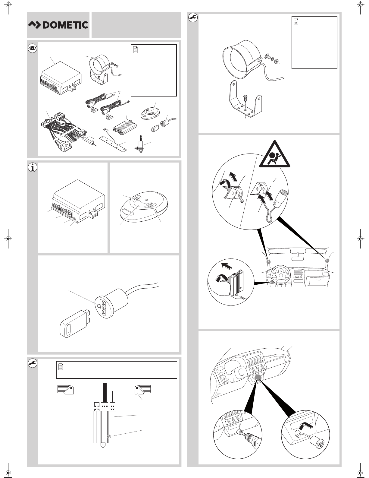
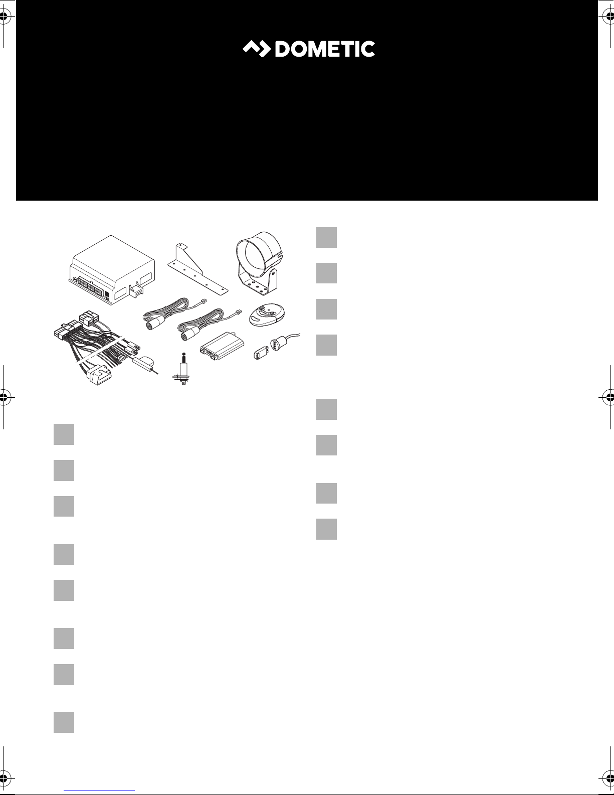
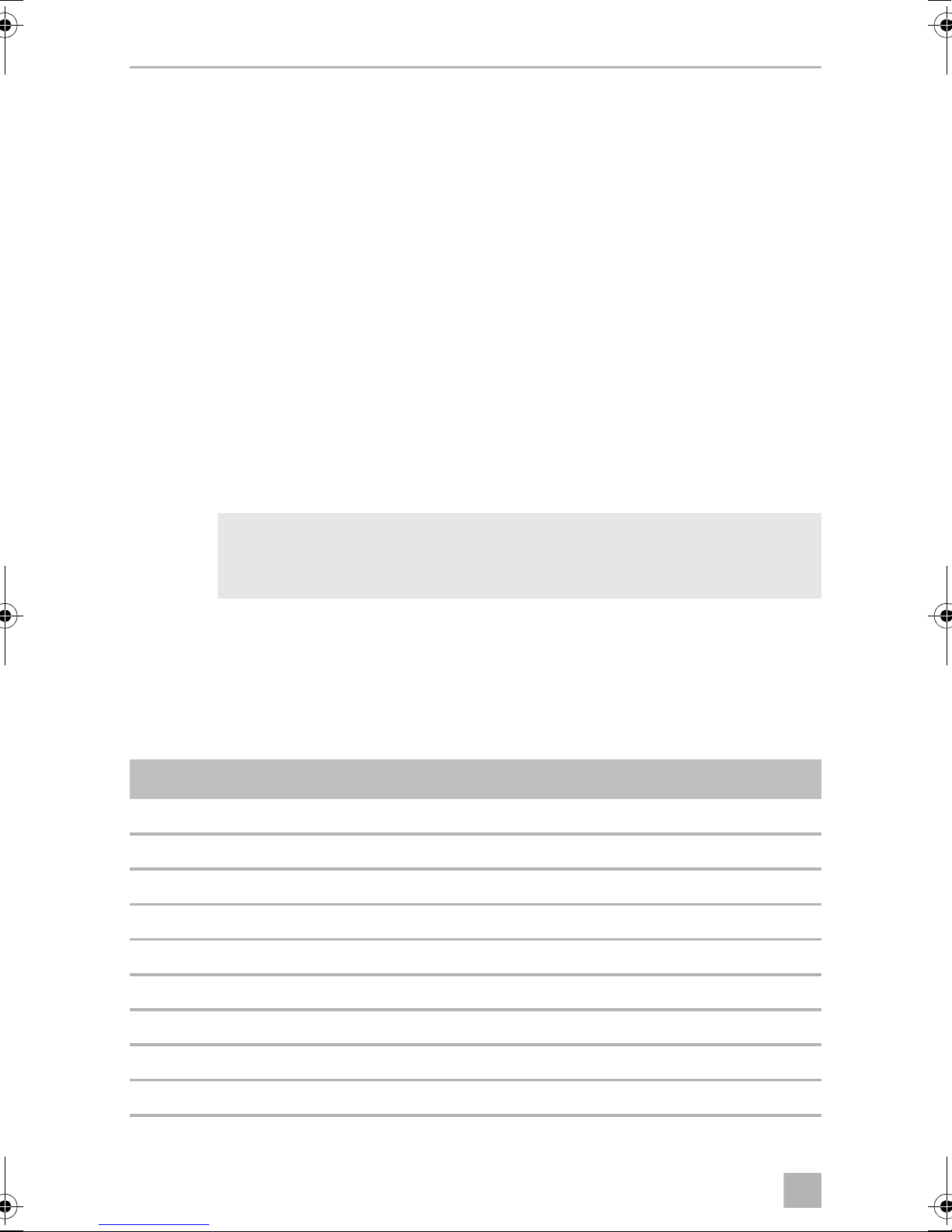
3Scope of delivery
See fig. 1
No. Quantity Description Ref. no.
1 1 Control unit 9101600015
2 1 Siren MS-670-SI
3 2 Ultrasonic sensors
4 1 Radio remote control 9101600016
5 1 Ultrasonic module (including sensors) MS-670-US
6 1 Electronic key (e-key) with base
7 1 Vehicle-specific cable set with OBD plug
8 1 Bonnet contact switch
9 1 Holder for bonnet contact switch and siren
– – Fastening and installation material
– – Installation and operating manual
4Accessories
Available as accessories (not included in the scope of delivery):
Description Ref. no.
Wireless infrared motion sensor 9101600013
Wireless magnetic contact switch 9101600014
Electronic key MS-670-EK
Electronic key base MS-670-ES
7
Page 10

EN
Intended use MS680
5 Intended use
MS680 (ref. no. 9101600012) is an alarm system and preset for a Fiat Ducato x290
(manufactured in 2015). Optionally, the alarm system can also be used for a Fiat
Ducato x250 (manufactured in 2011). For the connection data for a Fiat
Ducato x250, refer to chapter “Connection data for Fiat Ducato x250 (without
connection to the central locking system)” on page 15.
The alarm system offers additional protection against the theft of your vehicle and its
contents.
6 Technical description
6.1 Function description
MS680 is an alarm system with two ultrasonic sensors and a siren. The alarm system
can optionally be extended by up to 55 wireless infrared motion detectors and wireless magnetic contact switches. It is designed for vehicles with a voltage of 12 V and
is enabled or disabled when operating the original vehicle remote controls.
When the alarm system is activated, an alarm is triggered when one of the following
events occurs:
• A door opens.
• The boot is opened.
• The bonnet is opened.
• The ignition is turned on.
• An (optional) wireless sensor (radio magnetic contact, wireless motion) reports
movement.
The product offers you the following features:
• Activation and deactivation with original vehicle remote control
• Programmable acoustic and optical signals
• Interior monitoring of the passenger compartment using ultrasonic sensors
• Additional remote control to deactivate the interior monitoring
• E-key (electronic key) for programming and deactivating the alarm system
• Input for the connection of additional door contacts or a contact switch for the
bonnet or the boot.
8
Page 11
EN
MS680 Technical description
6.2 Control unit
See fig. 2
No. Description
1 Connection plug
2 Connection plug for 20-pin connection cable
3 Button (for programming)
4LED
6.3 Radio remote control
See fig. 3
No. Description
1 Deactivates the entire system (including unlocking of the doors upon connec-
tion of the central locking system, see chapter “Optional connection options”
on page 14)
2 Deactivates the interior monitoring system with an activated system or activates
the system without the interior monitoring (including interlock of doors upon
connection of the central locking system, see chapter “Optional connection
options” on page 14)
3 Activates the complete system (including interior monitoring and interlock of
the doors upon connection of the central locking system, see chapter
“Optional connection options” on page 14)
6.4 Ultrasonic module
See fig. 5
No. Description
1 Ultrasonic sensors
2 Ultrasonic module
3 Adjusting screw
9
Page 12
EN
Installing the alarm system MS680
6.5 Possible operating states
The alarm system has the following operating modes:
• Stand-by
The alarm system is constantly on stand-by as soon as it is installed and correctly
connected. However, it does not trigger the alarm when in stand-by.
• Activation time
The alarm system has an activation time of approx. 40 seconds.
As an optical indicator of the activation time, the LED is illuminated on the
electronic key base (fig. 4 1).
• Activated
If the alarm system is activated, it can trigger an alarm. This happens if someone
breaks into the door, opens the bonnet or enters the vehicle interior. If you wish
to drive off, you must first deactivate the alarm system. The system is then in
stand-by mode.
As an optical indicator for activation, the LED flashes on the electronic key base
(fig. 4 1).
• Alarm triggered
When an alarm has been triggered, it is indicated by optical and acoustic signals.
7 Installing the alarm system
NOTE
I
7.1 Installing the controller
➤ Select a suitable installation location.
➤ Install the control unit
– In the vehicle interior
– In such a way that you can read the LED and operate the button
– Under the dashboard
– Not in areas where strong electrical fields could cause interference,
– Not directly next to ventilator nozzles.
If you do not have sufficient technical knowledge for installing and
connecting the components in vehicles, you should have a specialist
install the alarm system in your vehicle.
e.g. ignition cables or central control electronics
➤ Screw the control unit firmly to the vehicle with the screws supplied or use
double-sided adhesive tape.
10
Page 13
EN
MS680 Installing the alarm system
7.2 Mounting the siren
See fig. 6
The siren can be mounted in the engine compartment.
NOTICE!
A
➤ Install the siren and the holder as shown in fig. 6.
7.3 Installing the ultrasonic module
See fig. 5
When mounting it, ensure that the installation location is
• Not in an area exposed to splashing water
• Not near the exhaust system
• Not accessible from underneath the vehicle, to ensure that it cannot
be tampered with.
➤ Install the ultrasonic module as illustrated in fig. 5.
7.4 Installing the ultrasonic sensors
See fig. 7
CAUTION!
!
➤ Align the ultrasonic sensors so that they point towards the centre between the
backrests of the front seats (of the passenger compartment).
➤ Lay the connecting cables of the sensors through the A-pillar to the ultrasonic
module.
Risk of injury if the airbag deploys!
Do not fit the ultrasonic sensors where an airbag may open.
11
Page 14
EN
Connecting the alarm system electrically MS680
7.5 Installing the bonnet contact switch
➤ Find a suitable location in the engine compartment and drill a hole with a
diameter of 8 mm.
➤ During installation make sure the distance to the closed bonnet is between
22 mm and 27 mm.
Use putty, for example, to check this distance.
You can further reduce the minimum distance by shortening the switch.
➤ Test the switch function after installation.
➤ Connect the bonnet contact switch with the grey wire (fig. 9) of the connection
cable of the siren in the engine compartment.
7.6 Mounting the base for the electronic key
See fig. 8
NOTE
I
When selecting the installation location, pay attention to the cable
lengths and whether the LED in the base is to be visible.
8 Connecting the alarm system
electrically
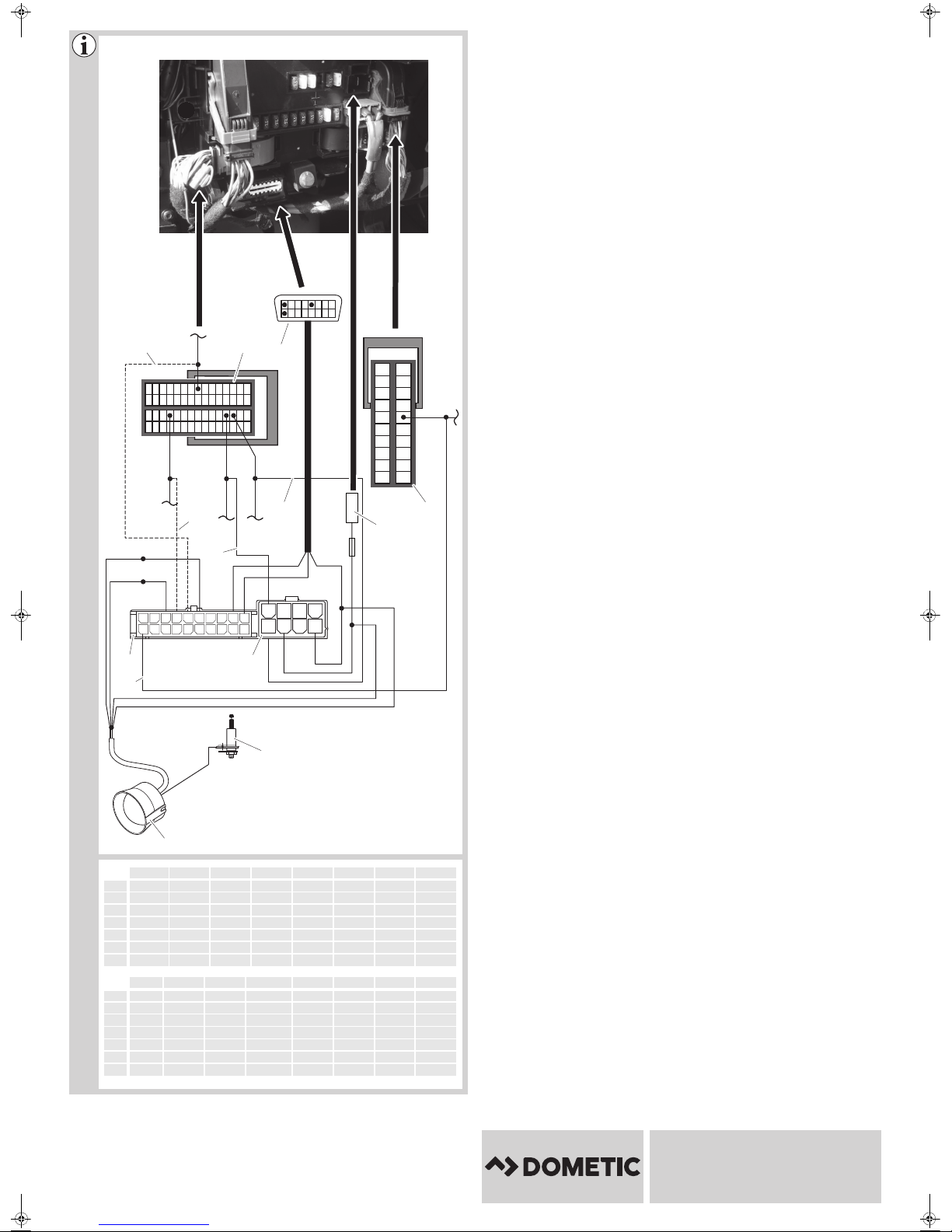
Fiat Ducato x290: You can find the circuit diagram in fig. 9.
No. Description
1 20-pin plug of the connection cable on the MS680 control unit
2 Connected positive terminal (ignition, terminal 15)
3 Central locking system
4 Central locking system
5 Right-hand indicator
6 Left-hand indicator
7OBD plug
8 60-pin green plug from the vehicle fuse box
9 20-pin black plug from the vehicle fuse box
12
Page 15

EN
MS680 Connecting the alarm system electrically
No. Description
10 8-pin plug of the connection cable on the MS680 control unit
11 Siren
12 Bonnet switch
13 Power supply connection
All plugs are coded so that you cannot connect them incorrectly.
8.1 Connecting the connection wires of the connection
cable (fig. 9)
Connecting the siren
➤ Insert the plug of the connection cable (fig. 9 11) into the connection of the
ultrasonic module.
➤ Guide this open cable end through the splash-protection wall into the passenger
compartment.
➤ Connect the red cable of the siren to the red cable of PIN 3 (8-pin plug of the
connection cable on the MS680 control unit) (fig. 9 10).
➤ Connect the blue cable of the siren to the blue/brown cable of PIN 18 (20-pin
plug of the connection cable on the MS680 control unit) (fig. 9 1).
➤ Connect the grey cable to the grey cable of PIN 15 (20-pin plug of the
connection cable on the MS680 control unit) (fig. 9 1).
➤ Connect the black cable to the black cable of PIN 1 (8-pin plug of the connection
cable on the MS680 control unit) (fig. 9 10).
Connecting the electronic key base
➤ Plug the red two-pin connector of the electronic key base (fig. 1 6) into the red
socket of the connection cable.
➤ Plug the white two-pin connector of the electronic key base (fig. 1 6) into the
white socket of the connection cable.
Violet (ignition plus)
➤ Connect the violet cable of PIN 10 (20-pin plug of the connection cable)
(fig. 9 1) to PIN 16 (20-pin black plug of the vehicle fuse box) (fig. 9 9).
13
Page 16

EN
Connecting the alarm system electrically MS680
Connecting the ultrasonic module (fig. 5 2)
Insert the white 3-pin plug of the connection cable into the connection of the
ultrasonic module.
Connecting the ultrasonic sensors (fig. 5 1)
➤ Insert the red plug of the ultrasonic sensor cable into the red connection of the
ultrasonic module (fig. 9 5).
➤ Insert the red plug of the ultrasonic sensor cable in the white connection of the
ultrasonic sensor (fig. 9 5).
Yellow (i n d icator )
➤ Connect the yellow cable of PIN 4 (8-pin plug of the connection cable on the
MS680 control unit) (fig. 9 10) to PIN 18 of the right indicator cable (60-pin
green plug of the vehicle fuse box) (fig. 9 8).
➤ Connect the yellow cable of PIN 8 (8-pin plug of the connection cable on the
MS680 control unit) (fig. 9 10) to PIN 19 of the left indicator cable (60-pin green
plug of the vehicle fuse box) (fig. 9 8).
8.2 Optional connection options
Brown/black (central locking system)
➤ Connect the brown/black cable of PIN 17 (20-pin plug of the connection cable)
(fig. 9 1) to PIN 27 (60-pin green plug from the vehicle fuse box) (fig. 9 8), if
you would like to also open and lock the vehicle with the additional hand-held
transmitter as well as activate and deactivate the MS680.
Grey/black (central locking system)
➤ Connect the grey/black cable of PIN 16 (20-pin plug of the connection cable)
(fig. 9 1) to PIN 53 (60-pin green plug from the vehicle fuse box) (fig. 9 8), if
you would like to also open and lock the vehicle with the additional hand-held
transmitter as well as activate and deactivate the MS680.
14
Page 17

EN
MS680 Connecting the alarm system electrically
Connection data for Fiat Ducato x250 (without connection to the central
locking system)
Yellow – indicator (standard)
➤ Connect the yellow cable of PIN 4 (8-pin plug of the connection cable on the
MS680 control unit) (fig. 9 10) to PIN 18 (blue/black cable) of the right
indicator cable (60-pin green/blue plug of the vehicle fuse box).
➤ Connect the yellow cable of PIN 8 (8-pin plug of the connection cable on the
MS680 control unit) (fig. 9 10) to PIN 19 (blue/white cable) of the left indicator
cable (60-pin green/blue plug of the vehicle fuse box).
Violet – ignition (+15)
➤ Connect the violet cable of PIN 10 (20-pin plug of the MS680 connection cable)
(fig. 9 1) to PIN 18 (light blue/grey) (20-pin black/blue plug of the vehicle fuse
box).
8.3 Connecting the connection cable
➤ Insert the 20-pin plug and the 8-pin plug of the connection cable into the
appropriate connection on the control unit of the alarm system (fig. 9 1 and
fig. 9 10).
➤ Insert the OBD plug (fig. 9 7) into the OBD connection underneath the vehicle
fuse box.
Red
➤ Insert the cable lug (fig. 9 13) of the red cable of PIN 3 of the 8-pin plug of the
connection cable into the MS680 control unit (fig. 9 10) in the open slot of the
vehicle fuse box (fig. 9).
15
Page 18
EN
Programming the alarm system MS680
9 Programming the alarm system
NOTE
The alarm system is pre-programmed for the Fiat Ducato x290.
I
9.1 Programming the vehicle code
The alarm system must be adjusted to the CAN bus of your vehicle type. The alarm
system is factory set to the vehicle code 131 for Fiat Ducato x250 and Fiat
Ducato x290.
If you need to reprogram the vehicle code, proceed as follows:
➤ Press the button (fig. 2 3) on the control unit and hold it down.
➤ When the LED on the control device (fig. 2 4) lights up, release the button.
✓ The LED goes out.
✓ After a pause of 4 seconds, the LED begins to flash.
➤ Count the number of flashes until the number agrees with the first number of your
vehicle code:
– One flash: Number 1
–Two flashes: Number2, …
– Nine flashes: Number 9
– Ten flashes: Number 0
➤ Press the button again.
✓ After a pause of 4 seconds, the LED begins to flash.
➤ Repeat the steps described above for all the digits of the vehicle code.
✓ After programming, the LED flashes the vehicle code.
➤ Test the alarm system by activating it with your remote control.
✓ When you correctly enter the vehicle code, the alarm system will be activated.
If the alarm system is not activated, you have not entered the vehicle code correctly.
Repeat the programming.
16
Page 19
EN
MS680 Programming the alarm system
9.2 Programming (optional)
You can program the functions listed in the following table. These functions remain
stored even if the battery is disconnected.
To program a function, proceed as follows:
➤ Start the ignition with the alarm system deactivated.
✓ The LED in the base of the electronic key illuminates for two seconds.
➤ Insert the electronic key into the key holder within these two seconds.
✓ To indicate that the programming mode has been activated, the LED flashes
three times and the siren emits three acoustic signals.
✓ The first function is activated.
NOTE
I
Each time you call up the programming mode in this way, all the values
of the individual functions are reset to the factory settings (see following
table).
Function
Optical signals
during activation/
deactivation
Acoustic signals Off Flashes twice The following acoustic signals are
Passive alarm Off Flashes three
Factory
setting
Off Flashes once This function can only be activated for
LED Programming
vehicles which do not emit any
optical signals (e.g. indicator) during
opening or closing.
emitted:
Activating: 2 signals
Deactivating: 1 long signal
Deactivating when the alarm has
been triggered: 1 brief signal
This function automatically activates
times
the alarm system 60 seconds after the
ignition has been switched off.
When this function is activated, the
convenience output and the ultrasonic sensors are deactivated.
17
Page 20
EN
Programming the alarm system MS680
Function
Door contact input Negative Flashes four
Factory
setting
LED Programming
The factory setting switches the
times
Flashes five
times
Flashes six
times
convenience output to negative so
that an external system can be
connected.
Do not change the value!
Do not change the value!
Modifying selected function
➤ Insert the electronic key in the electronic key base in order to modify the value of
the selected function.
✓ If the factory setting is “On”, the value is set to “Off” and vice versa.
✓ The siren emits an acoustic signal, and the LED on the electronic key base flashes
once.
Activating the next function
➤ Switch the ignition off and on again.
✓ The next function is activated.
➤ Modify the value as described above or switch the ignition off and on again to
activate the next function.
➤ Once you have called up all functions in sequence, switch the ignition off and on
again to confirm the entered values.
✓ The alarm system indicates the leaving of the programming mode and the storing
of the entered values by having the LED on the electronic key base flash three
times and the siren emit three acoustic signals.
18
Page 21
EN
MS680 Programming the alarm system
9.3 Programming new electronic keys and new wireless
contacts
The alarm system can be used with up to 55 sensors (electronic keys, wireless
movement sensors, wireless magnetic contact switches).
NOTE
I
Proceed as follows to program a new sensor:
➤ Deactivate the alarm.
➤ Switch the ignition on and off.
➤ Switch the ignition on and off again two more times within 4 seconds.
➤ Switch on the ignition and leave it on.
To program new sensors, the bonnet must be open (grey cable to
earth).
✓ The siren emits three acoustic signals, and the LED in the base of the electronic
key flashes three times (fig. 4 1).
➤ Insert the new electronic key in the key holder. Alternatively, press the program
button on the wireless sensor (see the operating manual of the wireless sensor).
✓ The sensor is automatically programmed.
✓ The LED flashes once when the programming operation is completed.
➤ Repeat the programming steps for each new sensor to be programmed.
➤ Switch the ignition off to exit the programming function.
✓ The siren emits three acoustic signals and the LED flashes three times.
9.4 Removing programmed devices
➤ Deactivate the alarm.
➤ Switch the ignition on and off.
➤ Switch the ignition on and off again two more times within 4 seconds.
➤ Switch on the ignition and leave it on.
✓ The siren emits three acoustic signals, and the LED in the base of the electronic
key flashes three times. The LED then lights up continuously (fig. 4 1).
➤ Remove the grey cable from earth (e.g. bonnet closed).
19
Page 22
EN
Using the alarm system MS680
➤ Wait 8 seconds to remove all programmed devices.
✓ Once all programmed devices have been removed, the LED turns off.
➤ Switch the ignition off.
✓ The siren emits three acoustic signals, and the LED in the base of the electronic
key flashes three times.
10 Using the alarm system
10.1 Activating the alarm system
To activate the alarm system manually, proceed as follows:
➤ Lock the vehicle with your remote control.
✓ The vehicle emits optical signals according to the factory settings.
NOTE
I
Activating the alarm system so that the vehicle can remain occupied
You can set the alarm system so that the alarm system does not trigger an alarm – to
spend the night in the vehicle, for example.
To do this, follow the steps below under A or B:
A) Cables for the central locking system are connected (fig. 9 3 and fig. 9 4):
➤ Press button (fig. 3 2) on the additional remote control.
✓ The vehicle locks and the alarm system is activated with deactivated interior
monitoring. (The wireless magnetic contact switches remain active.)
After roughly 40 seconds, the alarm system indicates that it is ready to
operate with flashing of the LED in the base of the electronic key.
20
Page 23

EN
MS680 Using the alarm system
B) Cables for the central locking system are not connected (fig. 9 3 and
fig. 9 4):
➤ Lock the vehicle with the original vehicle remote control.
✓ The vehicle is locked and the alarm system activated.
➤ Press button (fig. 3 2) on the additional remote control within 30 seconds.
✓ The alarm system deactivates the interior monitoring. (The wireless magnetic
contact switches remain active.)
10.2 Deactivating the alarm system
To deactivate the alarm system manually, proceed as follows:
➤ Open the vehicle with your remote control.
✓ The vehicle emits optical signals according to the factory settings.
NOTE
I
Sorting the alarm memory
The alarm system stores triggered alarms. If you hear a short acoustic signal during
deactivation, the alarm system has stored an alarm. You can read the alarm memory
and determine the reason for the alarm.
To do this, proceed as follows:
➤ Switch on the ignition and observe the LED on the base of the electronic key
(fig. 4 1).
✓ The LED shows the reason for the alarm:
LED display Reason for alarm
2 x On – 2 s Off – 2 x On Ignition key was activated Ten times
If an alarm was triggered, the siren emits a brief acoustic signal (see
chapter “Sorting the alarm memory” on page 21).
Duration of
display
3 x On – 2 s Off – 3 x On Doors opened Ten times
4 x On – 2 s Off – 4 x On Bonnet opened Ten times
6 x On – 2 s Off – 6 x On Ultrasonic module Ten times
8 x On – 2 s Off – 8 x On Wireless magnetic contact switch Ten times
9 x On – 2 s Off – 9 x On Wireless infrared motion sensor Ten times
21
Page 24
EN
Using the alarm system MS680
➤ Switch off the ignition when you want to end the display.
Deactivate the alarm system with the electronic key (emergency
deactivation / workshop mode)
In an emergency, you can deactivate the alarm system or put it into workshop mode
using the electronic key. This means the alarm system will no longer be activated by
the remote control and will remain completely switched off. Deactivation with the
electronic key is possible only if the alarm system was activated for at least
40 seconds (the LED on the base of the electronic key flashes).
➤ Open the vehicle door with the vehicle key.
✓ The alarm system triggers an alarm.
➤ Insert the electronic key in the electronic key base.
✓ The alarm is deactivated and in “workshop mode”.
The LED flashes every 16 seconds.
➤ In order to restore the normal function, you must insert the electronic key into the
key holder within 40 seconds after locking with the remote control.
✓ The alarm system can once again be activated and deactivated by your remote
control.
10.3 Setting the sensitivity of the ultrasonic sensors
(fig. 5)
The sensitivity of the ultrasonic sensors is set on the ultrasonic module.
➤ Turn the setting screw (fig. 5 3) on the underside of the ultrasonic module in the
direction of “+” to increase the sensitivity or
➤ ... turn the setting screw of the ultrasonic module in the opposite direction “–” to
reduce the sensitivity.
➤ To deactivate the ultrasonic module, turn the setting screw of the ultrasonic
sensor all the way in the direction “–”.
NOTE
I
If the ultrasonic sensors are set too sensitively, the alarm may be
triggered by a hailstorm, for example. For this reason you should not set
the sensitivity too high.
22
Page 25
EN
MS680 Care and cleaning
To find the right setting, proceed as follows:
➤ Deactivate the alarm system (see chapter “Deactivating the alarm system” on
page 21).
➤ Open the front side window about 20 cm.
➤ Activate the alarm system with the doors, bonnet and boot closed.
➤ Move an object into the vehicle interior from outside:
– If an alarm is triggered before you move the object into the vehicle,
reduce the sensitivity.
– If no alarm is triggered, increase the sensitivity.
11 Care and cleaning
NOTICE!
A
Do not use sharp or hard objects or cleaning agents for cleaning as these
may damage the product.
➤ Occasionally clean the product with a damp cloth.
12 Warranty
The statutory warranty period applies. If the product is defective, please contact the
manufacturer's branch in your country (see the back of the instruction manual for the
addresses) or your retailer.
For repair and guarantee processing, please send the following items:
• Defect components
• A copy of the receipt with purchasing date
• A reason for the claim or description of the fault
23
Page 26
EN
Disposal MS680
24
13 Disposal
➤ Place the packaging material in the appropriate recycling waste bins wherever
possible.
If you wish to finally dispose of the product, ask your local recycling centre
or specialist dealer for details about how to do this in accordance with the
M
applicable disposal regulations.
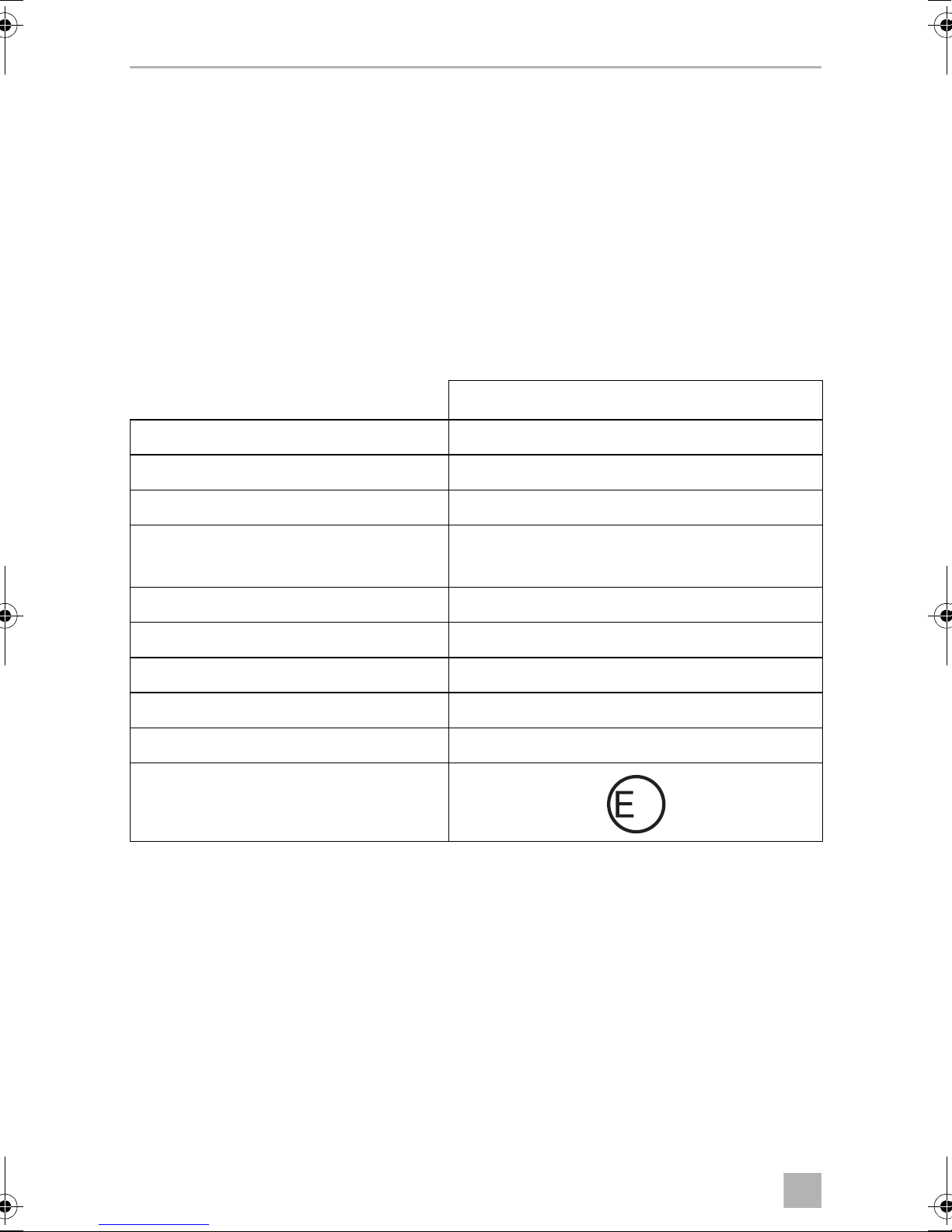
14 Technical data
MagicSafe MS680
Ref. no.: 9101600012
Operating voltage: 12 Vg
Input voltage: 9 – 15 Vg
Current: Max. 800 mA (activated)
Approx. 10 mA (deactivated) for 12 Vg
Output current for indicator signals: 8 A at 20 °C
Output current for engine block: 8 A at 20 °C
Output current for siren: 5 A
Alarm duration: 30 s
Operating temperature: –30 °C to 70 °C
Approval for control unit:
24
Page 27
EN
MS680 Technical data
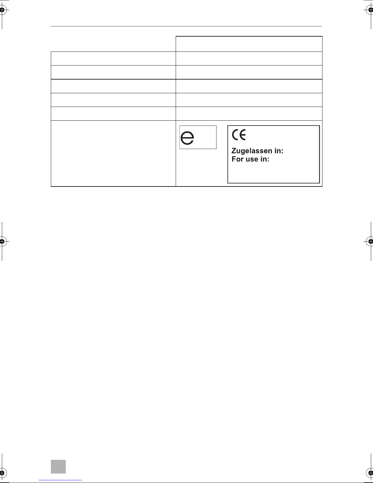
12
Hand-held transmitter
Transmission frequency: 433.92 MHz
Range: 10 – 20 m
Battery type: CR2032, 3 V
Operating temperature: -20 °C to 60 °C
Dimensions (L x W x H): 54 x 39 x 12 mm
Approval:
B, CH, D, DK, E, F, GB,
GR, I, IRL, L, NL, P
25
Page 28

DE
MS680
Bitte lesen Sie diese Anleitung vor Einbau und Inbetriebnahme sorgfältig
durch und bewahren Sie sie auf. Geben Sie sie im Falle einer Weitergabe
des Produktes an den Nutzer weiter.
Inhaltsverzeichnis
1 Erklärung der Symbole . . . . . . . . . . . . . . . . . . . . . . . . . . . . . . . . . . . . . . . . . 27
2 Sicherheits- und Einbauhinweise . . . . . . . . . . . . . . . . . . . . . . . . . . . . . . . . . 27
3 Lieferumfang . . . . . . . . . . . . . . . . . . . . . . . . . . . . . . . . . . . . . . . . . . . . . . . . . 30
4 Zubehör. . . . . . . . . . . . . . . . . . . . . . . . . . . . . . . . . . . . . . . . . . . . . . . . . . . . . 30
5 Bestimmungsgemäßer Gebrauch . . . . . . . . . . . . . . . . . . . . . . . . . . . . . . . . 30
6 Technische Beschreibung . . . . . . . . . . . . . . . . . . . . . . . . . . . . . . . . . . . . . . .31
7 Alarmanlage montieren . . . . . . . . . . . . . . . . . . . . . . . . . . . . . . . . . . . . . . . . 34
8 Alarmanlage elektrisch anschließen. . . . . . . . . . . . . . . . . . . . . . . . . . . . . . . 36
9 Alarmanlage programmieren . . . . . . . . . . . . . . . . . . . . . . . . . . . . . . . . . . . . 40
10 Alarmanlage verwenden . . . . . . . . . . . . . . . . . . . . . . . . . . . . . . . . . . . . . . . 45
11 Pflegen und reinigen. . . . . . . . . . . . . . . . . . . . . . . . . . . . . . . . . . . . . . . . . . . 48
12 Gewährleistung. . . . . . . . . . . . . . . . . . . . . . . . . . . . . . . . . . . . . . . . . . . . . . . 48
13 Entsorgen . . . . . . . . . . . . . . . . . . . . . . . . . . . . . . . . . . . . . . . . . . . . . . . . . . . 49
14 Technische Daten . . . . . . . . . . . . . . . . . . . . . . . . . . . . . . . . . . . . . . . . . . . . . 49
26
Page 29

DE
MS680 Erklärung der Symbole
1 Erklärung der Symbole
WARNUNG!
!
Sicherheitshinweis: Nichtbeachtung kann zu Tod oder schwerer
Verletzung führen.
VORSICHT!
Sicherheitshinweis: Nichtbeachtung kann zu Verletzungen führen.
!
ACHTUNG!
A
Nichtbeachtung kann zu Materialschäden führen und die Funktion des
Produktes beeinträchtigen.
HINWEIS
Ergänzende Informationen zur Bedienung des Produktes.
I
2 Sicherheits- und Einbauhinweise
Der Hersteller übernimmt in folgenden Fällen keine Haftung für Schäden:
• Montage- oder Anschlussfehler
• Beschädigungen am Produkt durch mechanische Einflüsse und Über-
spannungen
• Veränderungen am Produkt ohne ausdrückliche Genehmigung vom Hersteller
• Verwendung für andere als die in der Anleitung beschriebenen Zwecke
Beachten Sie die vom Fahrzeughersteller und vom Kfz-Handwerk vorgeschriebenen Sicherheitshinweise und Auflagen!
WARNUNG!
Unzureichende Leitungsverbindungen können zur Folge haben, dass
!
durch Kurzschluss
• Kabelbrände entstehen,
• der Airbag ausgelöst wird,
• elektronische Steuerungseinrichtungen beschädigt werden,
• elektrische Funktionen ausfallen (Blinker, Bremslicht, Hupe, Zündung,
Licht).
27
Page 30

DE
Sicherheits- und Einbauhinweise MS680
ACHTUNG!
Klemmen Sie wegen der Kurzschlussgefahr vor Arbeiten an der Fahrzeug-
A
Beachten Sie deshalb folgende Hinweise:
• Verwenden Sie bei Arbeiten an den folgenden Leitungen nur isolierte Kabelschuhe, Stecker und Flachsteckhülsen:
– 30 (Eingang von Batterie Plus direkt)
– 15 (Geschaltetes Plus, hinter Batterie)
– 31 (Rückleitung ab Batterie, Masse)
– L (Blinkerleuchten links)
– R (Blinkerleuchten rechts)
Verwenden Sie keine Lüsterklemmen.
• Verwenden Sie eine Krimpzange zum Verbinden der Kabel.
elektrik immer den Minuspol ab.
Bei Fahrzeugen mit Zusatzbatterie müssen Sie an dieser ebenfalls den
Minuspol abklemmen.
• Schrauben Sie das Kabel bei Anschlüssen an Leitung 31 (Masse)
– mit Kabelschuh und Zahnscheibe an eine fahrzeugeigene Masseschraube
oder
– mit Kabelschuh und Blechschraube an das Karosserieblech.
Achten Sie auf eine gute Masseübertragung!
Beim Abklemmen des Minuspols der Batterie verlieren alle flüchtigen Speicher der
Komfortelektronik ihre gespeicherten Daten.
• Folgende Daten müssen Sie je nach Fahrzeugausstattung neu einstellen:
–Radiocode
–Fahrzeuguhr
– Zeitschaltuhr
– Bordcomputer
– Sitzposition
Hinweise zur Einstellung finden Sie in der jeweiligen Bedienungsanleitung.
Beachten Sie folgende Hinweise bei der Montage:
VORSICHT!
!
• Befestigen Sie die im Fahrzeug montierten Teile so, dass sie sich unter
keinen Umständen (scharfes Abbremsen, Verkehrsunfall) lösen und zu
Verletzungen der Fahrzeuginsassen führen können.
28
Page 31

DE
MS680 Sicherheits- und Einbauhinweise
• Befestigen Sie verdeckt unter Verkleidungen anzubringende Teile des
Systems so, dass sie sich nicht lösen oder andere Teile und Leitungen
beschädigen und keine Fahrzeugfunktionen (Lenkung, Pedale usw.)
beeinträchtigen können.
• Beachten Sie immer die Sicherheitshinweise des Fahrzeugherstellers.
Einige Arbeiten (z. B. an Rückhaltesystemen wie Airbag usw.) dürfen
nur von geschultem Fachpersonal durchgeführt werden.
ACHTUNG!
A
Beachten Sie folgende Hinweise bei der Arbeit an elektrischen Teilen:
A
• Achten Sie beim Bohren auf ausreichenden Freiraum für den Bohrer-
austritt, um Schäden zu vermeiden.
• Entgraten Sie jede Bohrung und behandeln Sie diese mit Rostschutzmittel.
ACHTUNG!
• Benutzen Sie zum Prüfen der Spannung in elektrischen Leitungen nur
eine Diodenprüflampe oder ein Voltmeter.
Prüflampen mit einem Leuchtkörper nehmen zu hohe Ströme auf,
wodurch die Fahrzeugelektronik beschädigt werden kann.
• Beachten Sie beim Verlegen der elektrischen Anschlüsse, dass diese
– nicht geknickt oder verdreht werden,
– nicht an Kanten scheuern,
– nicht ohne Schutz durch scharfkantige Durchführungen verlegt
werden.
• Isolieren Sie alle Verbindungen und Anschlüsse.
• Sichern Sie die Kabel gegen mechanische Beanspruchung durch
Kabelbinder oder Isolierband, z. B. an vorhandenen Leitungen.
29
Page 32

DE
Lieferumfang MS680
3 Lieferumfang
Siehe Abb. 1
Nr. Menge Bezeichnung Art.-Nr.
1 1 Steuergerät 9101600015
2 1 Sirene MS-670-SI
3 2 Ultraschallsensoren
4 1 Funkfernbedienung 9101600016
5 1 Ultraschallmodul (inklusive Sensoren) MS-670-US
6 1 Elektronischer Schlüssel (E-Schlüssel) mit Sockel
7 1 Fahrzeugspezifischer Kabelsatz mit OBD-Stecker
8 1 Motorhauben-Kontaktschalter
9 1 Halter für Motorhauben-Kontaktschalter und
Sirene
– – Befestigungs- und Montagematerial
– – Montage- und Bedienungsanleitung
4Zubehör
Als Zubehör erhältlich (nicht im Lieferumfang enthalten):
Bezeichnung Art.-Nr.
Funk-Infrarotbewegungsmelder 9101600013
Funk-Magnetkontaktschalter 9101600014
Elektronischer Schlüssel MS-670-EK
E-Schlüssel Sockel MS-670-ES
30
Page 33

DE
MS680 Bestimmungsgemäßer Gebrauch
5 Bestimmungsgemäßer Gebrauch
MS680 (Art.-Nr. 9101600012) ist eine Alarmanlage und voreingestellt für einen Fiat
Ducato x290 (Baujahr 2015). Optional kann die Alarmanlage auch für einen Fiat
Ducato x250 (Baujahr 2011) verwendet werden. Die Anschlussdaten für einen Fiat
Ducato x250 entnehmen Sie dem Kapitel „Anschlussdaten für Fiat Ducato x250
(ohne Anbindung an die Zentralverriegelung)“ auf Seite 39.
Die Alarmanlage dient zum zusätzlichen Schutz gegen Diebstahl des Fahrzeugs und
seines Inhalts.
6 Technische Beschreibung
6.1 Funktionsbeschreibung
MS680 ist eine Alarmanlage, die über zwei Ultraschallsensoren und eine Sirene
verfügt. Die Alarmanlage kann optional um bis zu 55 Funk-Infrarotbewegungsmelder und Funk-Magnetkontaktschalter erweitert werden. Sie ist
ausgelegt für Fahrzeuge mit einer Bordspannung von 12 V und wird beim Betätigen
der originalen Fahrzeugfernbedienungen jeweils aktiviert oder deaktiviert.
Bei aktivierter Alarmanlage wird ein Alarm ausgelöst, sobald eines der folgenden
Ereignisse eintritt:
• Eine Tür wird geöffnet.
• Der Kofferraum wird geöffnet.
• Die Motorhaube wird geöffnet.
• Die Zündung wird eingeschaltet.
• Ein (optionaler) Funk-Sensor (Funk-Magnetkontakt, Funk-Bewegungsmelder)
meldet eine Bewegung.
Diese Funktionen bietet Ihnen das Produkt:
• Aktivierung und Deaktivierung mit der originalen Fahrzeug-Fernbedienung
• Programmierbare akustische und optische Signale
• Innenraumüberwachung der Fahrgastzelle über Ultraschallsensoren
• zusätzliche Fernbedienung zum Deaktivieren der Innenraumüberwachung
• E-Schlüssel (elektronischer Schlüssel) zur Programmierung und Deaktivierung
der Alarmanlage
• Eingang zum Anschluss zusätzlicher Türkontakte oder eines Kontaktschalters für
die Motorhaube oder den Kofferraum.
31
Page 34

DE
Technische Beschreibung MS680
6.2 Steuergerät
Siehe Abb. 2
Nr. Bezeichnung
1 Anschlussstecker
2 Anschlussstecker für 20-poliges Anschlusskabel
3 Taster (zum Programmieren)
4LED
6.3 Funkfernbedienung
Siehe Abb. 3
Nr. Bezeichnung
1 Deaktiviert das komplette System (inklusive Entriegelung der Türen bei
Anschluss der Zentralverriegelung, siehe Kapitel „Optionale Anschlussmöglichkeiten“ auf Seite 38)
2 Deaktiviert die Innenraumüberwachung bei aktiviertem System bzw. aktiviert
das System ohne die Innenraumüberwachung (inklusive Verriegelung der
Türen bei Anschluss der Zentralverriegelung, siehe Kapitel „Optionale
Anschlussmöglichkeiten“ auf Seite 38)
3 Aktiviert das komplette System (inklusive Innenraumüberwachung und
Verriegelung der Türen bei Anschluss der Zentralverriegelung, siehe Kapitel
„Optionale Anschlussmöglichkeiten“ auf Seite 38)
6.4 Ultraschallmodul
Siehe Abb. 5
Nr. Bezeichnung
1 Ultraschallsensoren
2 Ultraschallmodul
3 Einstellschraube
32
Page 35

DE
MS680 Technische Beschreibung
6.5 Mögliche Betriebszustände
Die Alarmanlage kennt folgende Betriebszustände:
• Betriebsbereit
Die Alarmanlage ist ständig betriebsbereit, sobald sie eingebaut und korrekt
angeschlossen ist. Sie löst in diesem Betriebszustand jedoch keinen Alarm aus.
• Einschaltzeit
Die Alarmanlage hat eine Einschaltzeit von ca. 40 Sekunden.
Als optische Anzeige für die Einschaltzeit leuchtet die LED am E-Schlüssel Sockel
(Abb. 4 1).
• Aktiviert
Wenn die Alarmanlage aktiviert ist, kann sie einen Alarm auslösen. Dies ist der
Fall, wenn z. B. eine Tür aufgebrochen, die Motorhaube geöffnet oder in den
Fahrzeuginnenraum eingestiegen wird. Wenn Sie wieder losfahren möchten,
müssen Sie die Alarmanlage deaktivieren. Diese ist dann wieder im Betriebszustand „betriebsbereit“.
Als optische Anzeige für die Aktivierung blinkt die LED am E-Schlüssel Sockel
(Abb. 4 1).
• Alarm ausgelöst
Wenn ein Alarm ausgelöst wurde, wird dies durch optische und akustische
Signale angezeigt.
33
Page 36

DE
Alarmanlage montieren MS680
7 Alarmanlage montieren
HINWEIS
I
7.1 Steuergerät montieren
➤ Wählen Sie einen geeigneten Montageort.
➤ Montieren Sie das Steuergerät
– im Fahrgastinnenraum,
– so, dass Sie die LED ablesen und den Taster bedienen können,
– unter dem Armaturenbrett,
– nicht im Einflussbereich starker elektrischer Felder, z. B. Zündleitungen oder
– nicht direkt an Luftaustrittsdüsen.
Wenn Sie nicht über ausreichende technische Kenntnisse für das
Einbauen und Anschließen von Komponenten in Fahrzeugen verfügen,
sollten Sie sich die Alarmanlage von einem Fachmann ins Fahrzeug
einbauen lassen.
Zentralsteuerelektronik,
➤ Schrauben Sie das Steuergerät mit den beiliegenden Schrauben fest oder
verwenden Sie doppelseitiges Klebeband.
7.2 Sirene montieren
Siehe Abb. 6
Die Sirene kann im Motorraum montiert werden.
ACHTUNG!
A
➤ Montieren Sie die Sirene und den Halter wie in Abb. 6 dargestellt.
Achten Sie bei der Montage darauf, dass der Montageort
• nicht im Spritzwasserbereich liegt,
• nicht in der Nähe der Auspuffanlage liegt,
• nicht von der Unterseite des Fahrzeugs zugänglich ist, um Sabotage
von außen zu verhindern.
7.3 Ultraschallmodul montieren
Siehe Abb. 5
➤ Montieren Sie das Ultraschallmodul wie in Abb. 5 dargestellt.
34
Page 37

DE
MS680 Alarmanlage montieren
7.4 Ultraschallsensoren montieren
Siehe Abb. 7
VORSICHT!
!
➤ Richten Sie die Ultraschallsensoren so aus, dass sie mittig zwischen die
Rückenlehnen der Vordersitze (Fahrgastkabine) zeigen.
➤ Verlegen Sie die Anschlusskabel der Sensoren durch die A-Säule zum
Ultraschallmodul.
Verletzungsgefahr beim Auslösen des Airbags!
Befestigen Sie die Ultraschallsensoren nicht im Wirkungsbereich eines
Airbags.
7.5 Motorhauben-Kontaktschalter montieren
➤ Suchen Sie im Motorraum eine geeignete Stelle aus und bohren Sie ein Loch mit
einem Durchmesser von 8 mm.
➤ Achten Sie bei der Montage darauf, dass der Abstand zur geschlossenen Haube
minimal 22 mm und maximal 27 mm beträgt.
Ermitteln Sie diese Abstände z. B. mit Knetmasse.
Sie können den minimalen Abstand z. B. durch Kürzen des Schalters noch
verringern.
➤ Prüfen Sie nach dem Einbau die Schaltfunktion.
➤ Verbinden Sie den Motorhauben-Kontaktschalter mit der grauen Ader (Abb. 9)
des Anschlusskabels der Sirene im Motorraum.
7.6 Sockel für E-Schlüssel montieren
Siehe Abb. 8
HINWEIS
I
Beachten Sie bei der Wahl des Montageortes die Kabellängen und ob
die LED im Sockel sichtbar sein soll.
35
Page 38

DE
Alarmanlage elektrisch anschließen MS680
8 Alarmanlage elektrisch anschließen
Fiat Ducato x290: Den Schaltplan finden Sie in Abb. 9.
Nr. Bezeichnung
1 20-poliger Stecker des Anschlusskabels am MS680-Steuergerät
2 Geschaltetes Plus (Zündung, Klemme 15)
3 Zentralverriegelung
4 Zentralverriegelung
5 Blinker rechts
6 Blinker links
7OBD-Stecker
8 60-poliger grüner Stecker vom Fahrzeugsicherungskasten
9 20-poliger schwarzer Stecker vom Fahrzeugsicherungskasten
10 8-poliger Stecker des Anschlusskabels am MS680-Steuergerät
11 Sirene
12 Haubenschalter
13 Anschluss Stromversorgung
Alle Stecker sind codiert, so dass Sie diese nicht verkehrt anschließen können.
36
Page 39

DE
MS680 Alarmanlage elektrisch anschließen
8.1 Anschlussleitungen des Anschlusskabels anschließen
(Abb. 9)
Sirene anschließen
➤ Stecken Sie den Stecker des Anschlusskabels (Abb. 9 11) auf den Anschluss der
Sirene.
➤ Führen Sie das offene Kabelende durch die Spritzwand in die Fahrgastzelle.
➤ Schließen Sie die rote Leitung der Sirene an die rote Leitung von PIN 3 (8-poliger
Stecker des Anschlusskabels am MS680-Steuergerät) an (Abb. 9 10).
➤ Schließen Sie die blaue Leitung der Sirene an die blau/braune Leitung von PIN 18
(20-poliger Stecker des Anschlusskabels am MS680-Steuergerät) an
(Abb. 9 1).
➤ Schließen Sie die graue Leitung an die graue Leitung von PIN 15 (20-poliger
Stecker des Anschlusskabels am MS680-Steuergerät) an (Abb. 9 1).
➤ Schließen Sie die schwarze Leitung an die schwarze Leitung von PIN 1 (8-poliger
Stecker des Anschlusskabels am MS680-Steuergerät) an (Abb. 9 10).
E-Schlüssel Sockel anschließen
➤ Stecken Sie den rot markierten zweipoligen Stecker des E-Schlüssel Sockels
(Abb. 1 6) auf die rote Buchse des Anschlusskabels.
➤ Stecken Sie den weißen zweipoligen Stecker des E-Schlüssel Sockels
(Abb. 1 6) auf die weiße Buchse des Anschlusskabels.
Violett (Zündungsplus)
➤ Schließen Sie die violette Leitung von PIN 10 (20-poliger Stecker des Anschluss-
kabels) (Abb. 9 1) an PIN 16 (20-poliger schwarzer Stecker Fahrzeugsicherungskasten) an (Abb. 9 9).
Ultraschallmodul anschließen (Abb. 5 2)
Stecken Sie den weißen dreipoligen Stecker des Anschlusskabels auf den Anschluss
des Ultraschallmoduls.
37
Page 40

DE
Alarmanlage elektrisch anschließen MS680
Ultraschallsensoren anschließen (Abb. 5 1)
➤ Stecken Sie den roten Stecker des Ultraschallsensorkabels in den roten
Anschluss des Ultraschallmoduls (Abb. 9 5).
➤ Stecken Sie den weißen Stecker des Ultraschallsensorkabels in den weißen
Anschluss des Ultraschallmoduls (Abb. 9 5).
Gelb (Blinker)
➤ Schließen Sie die gelbe Leitung von PIN 4 (8-poliger Stecker des Anschluss-
kabels an das MS680-Steuergerät) (Abb. 9 10) an PIN 18 der rechten Blinkerleitung (60-poliger grüner Stecker vom Fahrzeugsicherungskasten) an
(Abb. 9 8).
➤ Schließen Sie die gelbe Leitung von PIN 8 (8-poliger Stecker des Anschluss-
kabels an das MS680-Steuergerät) (Abb. 9 10) an PIN 19 der linken Blinkerleitung (60-poliger grüner Stecker vom Fahrzeugsicherungskasten) an
(Abb. 9 8).
8.2 Optionale Anschlussmöglichkeiten
Braun/Schwarz (Zentralverriegelung)
➤ Schließen Sie die braun/schwarze Leitung von PIN 17 (20-poliger Stecker des
Anschlusskabels) (Abb. 9 1) an PIN 27 (60-poliger grüner Stecker vom
Fahrzeugsicherungskasten) an (Abb. 9 8), wenn Sie das Fahrzeug auch mit
dem Zusatzhandsender öffnen und verschließen sowie die MS680 aktivieren
und deaktivieren möchten.
Grau/Schwarz (Zentralverriegelung)
➤ Schließen Sie die grau/schwarze Leitung von PIN 16 (20-poliger Stecker des
Anschlusskabels) (Abb. 9 1) an PIN 53 (60-poliger grüner Stecker vom
Fahrzeugsicherungskasten) an (Abb. 9 8), wenn Sie das Fahrzeug auch mit
dem Zusatzhandsender öffnen und verschließen sowie die MS680 aktivieren
und deaktivieren möchten.
38
Page 41

DE
MS680 Alarmanlage elektrisch anschließen
Anschlussdaten für Fiat Ducato x250 (ohne Anbindung an die Zentralverriegelung)
Gelb – Blinker (Standard)
➤ Schließen Sie die gelbe Leitung von PIN 4 (8-poliger Stecker des Anschluss-
kabels an das MS680-Steuergerät) (Abb. 9 10) an PIN 18 (blau/schwarze
Leitung) der rechten Blinkerleitung (60-poliger grün/blauer Stecker vom
Fahrzeugsicherungskasten).
➤ Schließen Sie die gelbe Leitung von PIN 8 (8-poliger Stecker des Anschluss-
kabels an das MS680-Steuergerät) (Abb. 9 10) an PIN 19 (blau/weiße Leitung)
der linken Blinkerleitung (60-poliger grün/blauer Stecker vom Fahrzeugsicherungskasten).
Violett – Zündung (+15)
➤ Schließen Sie die violette Leitung von PIN 10 (20-poliger Stecker des
MS680-Anschlusskabels) (Abb. 9 1) an PIN 18 (hellblau/grau) (20-poliger
schwarz/blauer Stecker vom Fahrzeugsicherungskasten) an.
8.3 Anschlusskabel anschließen
➤ Stecken Sie den 20-poligen Stecker und den 8-poligen Stecker des Anschluss-
kabels auf den entsprechenden Anschluss am Steuergerät der Alarmanlage
(Abb. 9 1 und Abb. 9 10).
➤ Stecken Sie den OBD-Stecker (Abb. 9 7) auf den OBD-Anschluss unterhalb des
Fahrzeugsicherungskastens.
Rot
➤ Stecken Sie den Steckschuh (Abb. 9 13) der roten Leitung von PIN 3 des
8-poligen Steckers des Anschlusskabels am MS680-Steuergerät (Abb. 9 10)
auf den freien Steckplatz des Fahrzeugsicherungskastens (Abb. 9).
39
Page 42

DE
Alarmanlage programmieren MS680
9 Alarmanlage programmieren
HINWEIS
Die Alarmanlage ist für den Fiat Ducato x290 vorprogrammiert.
I
9.1 Fahrzeug-Code programmieren
Die Alarmanlage muss auf den CAN-Bus Ihres Fahrzeugtyps abgestimmt sein. Die
Alarmanlage ist werksseitig auf den Fahrzeug-Code 131 für Fiat Ducato x250 und
Fiat Ducato x290 eingestellt.
Gehen Sie wie folgt vor, wenn Sie den Fahrzeug-Code erneut programmieren
müssen:
➤ Drücken Sie den Taster (Abb. 2 3) am Steuergerät und halten Sie ihn gedrückt.
➤ Wenn die LED am Steuergerät (Abb. 2 4) leuchtet, lassen Sie den Taster los.
✓ Die LED erlischt.
✓ Nach einer Pause von etwa 4 Sekunden fängt die LED an zu blinken.
➤ Zählen Sie die Anzahl der Blinksignale, bis die Anzahl mit der ersten Nummer
Ihres Fahrzeug-Codes übereinstimmt:
– Einmal blinken: Ziffer 1
– Zweimal blinken: Ziffer 2, …
– Neunmal blinken: Ziffer 9
– Zehnmal blinken: Ziffer 0
➤ Drücken Sie den Taster erneut.
✓ Nach einer Pause von etwa 4 s fängt die LED an zu blinken.
➤ Wiederholen Sie die oben beschriebenen Schritte für alle Ziffern des Fahrzeug-
Codes.
✓ Nach der Programmierung blinkt die LED den Fahrzeug-Code.
➤ Testen Sie die Alarmanlage, indem Sie diese mit Ihrer Fernbedienung aktivieren.
✓ Wenn Sie den Fahrzeug-Code richtig eingegeben haben, wird die Alarmanlage
aktiviert.
Wenn die Alarmanlage nicht aktiviert wird, haben Sie den Fahrzeug-Code falsch
eingegeben. Wiederholen Sie die Programmierung.
40
Page 43

DE
MS680 Alarmanlage programmieren
9.2 Programmieren (optional)
Sie können die in der folgenden Tabelle aufgeführten Funktionen programmieren.
Diese Funktionen bleiben auch dann gespeichert, wenn die Batterie abgeklemmt
wird.
Gehen Sie wie folgt vor, um die gewünschte Funktion zu programmieren:
➤ Schalten Sie die Zündung bei deaktivierter Alarmanlage ein.
✓ Die LED im Sockel des E-Schlüssels leuchtet für zwei Sekunden.
➤ Stecken Sie innerhalb dieser zwei Sekunden den E-Schlüssel in die Schlüssel-
aufnahme.
✓ Das System zeigt die Aktivierung des Programmiermodus an, indem die LED
dreimal blinkt und die Sirene drei akustische Signale abgibt.
✓ Die erste Funktion ist aktiviert.
I
HINWEIS
Jedes Mal, wenn Sie den Programmiermodus so aufrufen, werden alle
Werte der einzelnen Funktionen auf die Werkseinstellung zurück
gesetzt (siehe folgende Tabelle).
41
Page 44

DE
Alarmanlage programmieren MS680
Funktion
Optische Signale beim
Aktivieren/
Deaktivieren
Akustische Signale Aus blinkt
Passiver Alarm Aus blinkt dreimal Diese Funktion aktiviert die Alarm-
Werkseinstellung
Aus blinkt einmal Diese Funktion kann nur bei Fahr-
LED Programmierung
zeugen aktiviert werden, die beim
Öffnen oder Schließen keine
optischen Signale (z. B. Blinker)
ausgeben.
Folgende akustische Signale
zweimal
werden ausgegeben:
Aktivieren: 2 Signale
Deaktivieren: 1 langes Signal
Deaktivieren bei ausgelöstem
Alarm: 1 kurzes Signal
anlage automatisch 60 s nachdem
dem Ausschalten der Zündung.
Wenn diese Funktion aktiviert ist,
sind der Komfortausgang und die
Ultraschallsensoren deaktiviert.
Eingang Türkontakt Negativ blinkt viermal Die Werkseinstellung schaltet den
Komfortausgang negativ, so dass
eine externe Anlage angeschlossen werden kann.
blinkt fünfmal Wert nicht ändern!
blinkt
sechsmal
Wert nicht ändern!
Ausgewählte Funktion ändern
➤ Stecken Sie den E-Schlüssel in den E-Schlüssel Sockel, um den Wert der
ausgewählten Funktion zu ändern.
✓ Wenn die Werkseinstellung „Ein“ ist, wird der Wert auf „Aus“ gesetzt und
umgekehrt.
✓ Die Sirene gibt ein akustisches Signal aus und die LED im E-Schlüssel Sockel
blinkt einmal.
42
Page 45

DE
MS680 Alarmanlage programmieren
Nächste Funktion aktivieren
➤ Schalten Sie die Zündung aus und wieder ein.
✓ Die nächste Funktion ist aktiviert.
➤ Ändern Sie den Wert wie oben beschrieben oder schalten Sie die Zündung aus
und wieder ein, um die nächste Funktion zu aktivieren.
➤ Nachdem Sie alle Funktionen nacheinander aufgerufen haben, schalten Sie zur
Bestätigung der eingegebenen Werte die Zündung nochmal aus und wieder
ein.
✓ Die Alarmanlage zeigt das Verlassen des Programmiermodus und die
Speicherung der eingegebenen Werte an, indem die LED im E-Schlüssel Sockel
dreimal blinkt und die Sirene drei akustische Signale abgibt.
9.3 Neuen E-Schlüssel und neue Funk-Kontakte anlernen
Die Alarmanlage kann mit bis zu 55 Sensoren (E-Schlüsseln, Funk-Bewegungsmelder, Funk-Magnetkontaktschalter) verwendet werden.
HINWEIS
I
Gehen Sie wie folgt vor, um einen neuen Sensor anzulernen:
➤ Deaktivieren Sie den Alarm.
➤ Schalten Sie die Zündung ein und aus.
➤ Schalten Sie die Zündung innerhalb von 4 Sekunden noch zweimal wieder ein
und aus.
➤ Schalten Sie die Zündung ein und lassen Sie sie eingeschaltet.
✓ Die Sirene gibt drei akustische Signale ab, und die LED im Sockel des
E-Schlüssels blinkt dreimal (Abb. 4 1).
➤ Stecken Sie den neuen E-Schlüssel in die Schlüsselaufnahme. Alternativ drücken
Sie die Anlerntaste am Funk-Sensor (siehe Bedienungsanleitung des FunkSensors).
Zum Programmieren neuer Sensoren muss die Motorhaube geöffnet
sein (graue Leitung an Masse)
✓ Der Sensor wird automatisch angelernt.
✓ Die LED blinkt einmal, wenn das Anlernen abgeschlossen ist.
43
Page 46

DE
Alarmanlage programmieren MS680
➤ Wiederholen Sie die Handlungsschritte zum Anlernen für jeden neu
anzulernenden Sensor.
➤ Schalten Sie die Zündung aus, um die Anlernfunktion zu beenden.
✓ Die Sirene gibt drei akustische Signale ab, und die LED blinkt dreimal.
9.4 Angelernte Geräte entfernen
➤ Deaktivieren Sie den Alarm.
➤ Schalten Sie die Zündung ein und aus.
➤ Schalten Sie die Zündung innerhalb von 4 Sekunden noch zweimal wieder ein
und aus.
➤ Schalten Sie die Zündung ein und lassen Sie sie eingeschaltet.
✓ Die Sirene gibt drei akustische Signale ab, und die LED im Sockel des
E-Schlüssels blinkt dreimal. Anschließend leuchtet die LED dauerhaft
(Abb. 4 1).
➤ Entfernen Sie die graue Leitung von der Masse (z. B. Motorhaube geschlossen).
➤ Warten Sie 8 Sekunden, um alle angelernten Geräte zu entfernen.
✓ Wenn alle angelernten Geräte entfernt wurden, schaltet sich die LED aus.
➤ Schalten Sie die Zündung aus.
✓ Die Sirene gibt drei akustische Signale ab, und die LED im Sockel des
E-Schlüssels blinkt dreimal.
44
Page 47

DE
MS680 Alarmanlage verwenden
10 Alarmanlage verwenden
10.1 Alarmanlage aktivieren
Gehen Sie wie folgt vor, um die Alarmanlage manuell zu aktivieren:
➤ Verschließen Sie das Fahrzeug mit Ihrer Fernbedienung.
✓ Das Fahrzeug gibt optische Signale entsprechend der Werkseinstellung ab.
HINWEIS
I
Alarmanlage so aktivieren, dass das Fahrzeug besetzt bleiben kann
Sie können die Alarmanlage so einstellen, dass die Alarmanlage keinen Alarm
auslöst, z. B. um im Fahrzeug zu übernachten.
Die Alarmanlage zeigt nach ca. 40 Sekunden durch Blinken der LED im
Sockel des E-Schlüssels die Betriebsbereitschaft an.
Führen Sie dazu die nachfolgenden Schritte unter A oder B aus:
A) Leitungen für Zentralverriegelung sind angeschlossen (Abb. 9 3 und
Abb. 9 4):
➤ Drücken Sie die Taste (Abb. 3 2) der Zusatzfunkfernbedienung.
✓ Das Fahrzeug verschließt sich und die Alarmanlage wird mit abgeschalteter
Innenraumüberwachung aktiviert. (Die Funk-Magnetkontaktschalter bleiben
aktiv.)
B) Leitungen für Zentralverriegelung sind nicht angeschlossen (Abb. 9 3 und
Abb. 9 4):
➤ Verschließen Sie das Fahrzeug mit der originalen Fahrzeugfernbedienung.
✓ Das Fahrzeug wird verschlossen und die Alarmanlage aktiviert.
➤ Drücken Sie innerhalb von 30 Sekunden die Taste (Abb. 3 2) der
Zusatzfunkfernbedienung.
✓ Die Alarmanlage deaktiviert die Innenraumüberwachung. (Die Funk-Magnet-
kontaktschalter bleiben aktiv.)
45
Page 48

DE
Alarmanlage verwenden MS680
10.2 Alarmanlage deaktivieren
Gehen Sie wie folgt vor, um die Alarmanlage zu deaktivieren:
➤ Öffnen Sie das Fahrzeug mit Ihrer Fernbedienung.
✓ Das Fahrzeug gibt optische Signale entsprechend der Werkseinstellung ab.
HINWEIS
I
Alarmspeicher auslesen
Die Alarmanlage speichert ausgelöste Alarme. Wenn Sie bei der Deaktivierung ein
kurzes akustisches Signal hören, hat die Alarmanlage einen Alarm gespeichert. Sie
können den Alarmspeicher auslesen und den Grund für den Alarm bestimmen.
Gehen Sie dazu wie folgt vor:
Falls ein Alarm ausgelöst wurde, gibt die Sirene ein kurzes akustisches
Signal ab (siehe Kapitel „Alarmspeicher auslesen“ auf Seite 46).
➤ Schalten Sie die Zündung ein und achten Sie auf die LED am Sockel des
E-Schlüssels (Abb. 4 1).
✓ Die LED zeigt den Alarmgrund an:
LED-Anzeige Alarmgrund
2 x An – 2 s Aus – 2 x An Zündschlüssel wurde betätigt zehnmal
3 x An – 2 s Aus – 3 x An Türen geöffnet zehnmal
4 x An – 2 s Aus – 4 x An Motorhaube geöffnet zehnmal
6 x An – 2 s Aus – 6 x An Ultraschallmodul zehnmal
8 x An – 2 s Aus – 8 x An Funk-Magnetkontaktschalter zehnmal
9 x An – 2 s Aus – 9 x An Funk-Infrarotbewegungsmelder zehnmal
➤ Schalten Sie die Zündung aus, wenn Sie die Anzeige beenden möchten.
Dauer der
Anzeige
46
Page 49

DE
MS680 Alarmanlage verwenden
Alarmanlage mit dem E-Schlüssel deaktivieren (Notfall-Deaktivierung /
Werkstattmodus)
Sie können die Alarmanlage mit dem E-Schlüssel im Notfall deaktivieren oder in den
Werkstattmodus versetzen. Dadurch wird die Alarmanlage nicht mehr über Ihre
Fernbedienung aktiviert, sondern bleibt komplett ausgeschaltet. Die Deaktivierung
mit dem E-Schlüssel ist nur möglich, wenn die Alarmanlage für mindestens
40 Sekunden aktiviert war (die LED am Sockel des E-Schlüssels blinkt).
➤ Öffnen Sie die Fahrertür mit dem Fahrzeugschlüssel.
✓ Die Alarmanlage löst einen Alarm aus.
➤ Stecken Sie den E-Schlüssel in den E-Schlüssel Sockel.
✓ Die Alarmanlage ist deaktiviert und im Betriebszustand „Werkstattmodus“.
Die LED blinkt alle 16 Sekunden.
➤ Um die normale Funktion wiederherzustellen, müssen Sie den E-Schlüssel
innerhalb von 40 Sekunden nach dem Verschließen mit der Fernbedienung in
die Schlüsselaufnahme stecken.
✓ Die Alarmanlage kann wieder durch Ihre Fernbedienung aktiviert und deaktiviert
werden.
10.3 Empfindlichkeit der Ultraschallsensoren einstellen
(Abb. 5)
Die Empfindlichkeit der Ultraschallsensoren stellen Sie am Ultraschallmodul ein.
➤ Drehen Sie die Einstellschraube (Abb. 5 3) auf der Unterseite des Ultraschall-
moduls in Richtung „+“, um die Empfindlichkeit zu erhöhen oder
➤ ... drehen Sie die Einstellschraube des Ultraschallmoduls in die entgegen-
gesetzte Richtung „–“, um die Empfindlichkeit zu verringern.
➤ Um das Ultraschallmodul zu deaktivieren, drehen Sie die Einstellschraube des
Ultraschallsensors bis zum Anschlag in Richtung „–“.
HINWEIS
I
Wenn die Ultraschallsensoren zu empfindlich eingestellt sind, kann z. B.
durch Hagelschauer ein Alarm ausgelöst werden. Stellen Sie deshalb
die Empfindlichkeit nicht zu hoch ein.
47
Page 50

DE
Pflegen und reinigen MS680
Gehen Sie wie folgt vor, um die richtige Einstellung zu finden:
➤ Deaktivieren Sie die Alarmanlage (siehe Kapitel „Alarmanlage deaktivieren“ auf
Seite 46).
➤ Öffnen Sie die vorderen Seitenfenster um etwa 20 cm.
➤ Aktivieren Sie die Alarmanlage bei geschlossenen Türen und Motor- und Koffer-
raumhaube.
➤ Bewegen Sie von außen ein Objekt ins Fahrzeuginnere:
– Wenn ein Alarm ausgelöst wird, bevor Sie das Objekt ins Fahrzeug bewegen,
verringern Sie die Empfindlichkeit.
– Wenn kein Alarm ausgelöst wird, erhöhen Sie die Empfindlichkeit.
11 Pflegen und reinigen
ACHTUNG!
A
➤ Reinigen Sie das Produkt gelegentlich mit einem feuchten Tuch.
Keine scharfen oder harten Gegenstände oder Reinigungsmittel zur
Reinigung verwenden, da dies zu einer Beschädigung des Produktes
führen kann.
12 Gewährleistung
Es gilt die gesetzliche Gewährleistungsfrist. Sollte das Produkt defekt sein, wenden
Sie sich bitte an die Niederlassung des Herstellers in Ihrem Land (Adressen siehe
Rückseite der Anleitung) oder an Ihren Fachhändler.
Zur Reparatur- bzw. Gewährleistungsbearbeitung müssen Sie Folgendes einschicken:
• defekte Komponenten,
• eine Kopie der Rechnung mit Kaufdatum,
• einen Reklamationsgrund oder eine Fehlerbeschreibung.
48
Page 51

DE
MS680 Entsorgen
24
13 Entsorgen
➤ Geben Sie das Verpackungsmaterial möglichst in den entsprechenden
Recycling-Müll.
Wenn Sie das Produkt endgültig außer Betrieb nehmen, informieren Sie
sich bitte beim nächsten Recyclingcenter oder bei Ihrem Fachhändler
M
über die zutreffenden Entsorgungsvorschriften.
14 Technische Daten
MagicSafe MS680
Artikel-Nr.: 9101600012
Betriebsspannung: 12 Vg
Versorgungsspannung: 9 – 15 Vg
Stromaufnahme: max. 800 mA (aktiviert)
ca. 10 mA (deaktiviert) bei 12 Vg
Ausgangsstrom für Blinkersignale: 8 A bei 20 °C
Ausgangsstrom für Motorsperre: 8 A bei 20 °C
Ausgangsstrom für Sirene: 5 A
Alarmdauer: 30 s
Betriebstemperatur: –30 °C bis +70 °C
Zulassung Steuergerät:
49
Page 52

DE
Technische Daten MS680
12
Handsender
Sendefrequenz: 433,92 MHz
Reichweite: 10 – 20 m
Batterietyp: CR2032, 3 V
Betriebstemperatur: –20 °C bis +60 °C
Abmessungen (L x B x H): 54 x 39 x 12 mm
Zulassung:
B, CH, D, DK, E, F, GB,
GR, I, IRL, L, NL, P
50
Page 53

FR
MS680
Veuillez lire attentivement cette notice avant le montage et la mise en
service. Veuillez ensuite la conserver. En cas de passer le produit, veuillez
le transmettre au nouvel acquéreur.
Table des matières
1 Symboles. . . . . . . . . . . . . . . . . . . . . . . . . . . . . . . . . . . . . . . . . . . . . . . . . . . . 52
2 Consignes de sécurité et instructions de montage. . . . . . . . . . . . . . . . . . . 52
3 Contenu de la livraison . . . . . . . . . . . . . . . . . . . . . . . . . . . . . . . . . . . . . . . . . 56
4 Accessoires . . . . . . . . . . . . . . . . . . . . . . . . . . . . . . . . . . . . . . . . . . . . . . . . . . 56
5 Usage conforme . . . . . . . . . . . . . . . . . . . . . . . . . . . . . . . . . . . . . . . . . . . . . . 57
6 Description technique . . . . . . . . . . . . . . . . . . . . . . . . . . . . . . . . . . . . . . . . . 57
7 Montage du système d’alarme. . . . . . . . . . . . . . . . . . . . . . . . . . . . . . . . . . . 60
8 Raccordement électrique du système d’alarme . . . . . . . . . . . . . . . . . . . . . 62
9 Programmation du système d’alarme . . . . . . . . . . . . . . . . . . . . . . . . . . . . . 66
10 Utilisation du système d’alarme . . . . . . . . . . . . . . . . . . . . . . . . . . . . . . . . . . .71
11 Entretien et nettoyage . . . . . . . . . . . . . . . . . . . . . . . . . . . . . . . . . . . . . . . . . 74
12 Garantie. . . . . . . . . . . . . . . . . . . . . . . . . . . . . . . . . . . . . . . . . . . . . . . . . . . . . 75
13 Élimination des déchets . . . . . . . . . . . . . . . . . . . . . . . . . . . . . . . . . . . . . . . . 75
14 Caractéristiques techniques. . . . . . . . . . . . . . . . . . . . . . . . . . . . . . . . . . . . . 76
51
Page 54

FR
Symboles MS680
1Symboles
AVERTISSEMENT !
!
!
A
Consigne de sécurité : le non-respect de ces consignes peut entraîner
la mort ou de graves blessures.
ATTENTION !
Consigne de sécurité : le non-respect de ces consignes peut entraîner
des blessures.
AVIS !
Le non-respect de ces consignes peut entraîner des dommages
matériels et des dysfonctionnements du produit.
REMARQUE
Informations complémentaires sur l'utilisation du produit.
I
2 Consignes de sécurité et instructions de
montage
Le fabricant décline toute responsabilité pour des dommages dans les cas suivants :
• des défauts de montage ou de raccordement
• des influences mécaniques et des surtensions ayant endommagé le matériel
• des modifications apportées au produit sans autorisation explicite de la part du
fabricant
• une utilisation différente de celle décrite dans la notice
52
Page 55

FR
MS680 Consignes de sécurité et instructions de montage
Respectez les consignes de sécurité et autres prescriptions imposées par
le fabricant du véhicule et par les professionnels de l'automobile !
AVERTISSEMENT !
Tout branchement électrique inadéquat peut entraîner un court-circuit
!
A
causant
• la combustion de câbles,
• le déclenchement de l'airbag,
• l’endommagement des dispositifs électroniques de commande,
• la défaillance des fonctions électriques (clignotants, feux-stop, klaxon,
allumage, éclairage).
AVIS !
Débranchez toujours la borne négative avant de procéder à des travaux
sur les éléments électriques du véhicule afin d’éviter tout risque de courtcircuit.
Sur les véhicules équipés d’une batterie supplémentaire, vous devez également débrancher le pôle négatif de cette dernière.
Veuillez donc respecter les consignes suivantes :
• Pour tous les travaux sur les lignes électriques suivantes, n’utilisez que des cosses
de câble, fiches et alvéoles pour contacts plats isolés :
– 30 (entrée directe pôle positif de la batterie)
– 15 (pôle positif connecté, derrière la batterie)
– 31 (ligne de retour à partir de la batterie, masse)
– L (clignotants gauches)
– R (clignotants droits)
N’utilisez pas de dominos.
• Utilisez une pince à sertir pour relier les câbles.
• Pour les raccordements à la ligne électrique 31 (masse), vissez le câble
– à une vis de masse du véhicule, avec une cosse et une rondelle crantée, ou
bien
– à la carrosserie, avec une cosse et une vis à tôle.
Veillez à une bonne transmission de la masse !
53
Page 56

FR
Consignes de sécurité et instructions de montage MS680
Lorsque vous débranchez le pôle négatif de la batterie, les mémoires volatiles de
l’électronique de confort perdent toutes les données enregistrées.
• Vous devez procéder à un nouveau réglage des données suivantes en fonction
de l’équipement du véhicule :
–code radio
– horloge du véhicule
–minuterie
– ordinateur de bord
– position du siège
Les instructions de réglage figurent dans les notices d’utilisation
correspondantes.
Veuillez respecter les consignes suivantes lors du montage :
ATTENTION !
!
A
• Fixez les pièces installées dans le véhicule de manière à ce qu’elles ne
puissent en aucun cas se desserrer (freinage abrupt, accident) et risquer de causer des blessures aux occupants du véhicule.
• Fixez les pièces du système sous l'habillage de telle sorte qu'elles ne
puissent pas se détacher, endommager d'autres pièces ou
connexions, ni gêner le fonctionnement du véhicule (direction,
pédales, etc.).
• Respectez toujours les consignes de sécurité du fabricant du véhicule.
Certains travaux (p. ex. au niveau des systèmes de retenue, AIRBAG,
etc.) doivent être effectués uniquement par un personnel spécialisé
ayant reçu une formation correspondante.
AVIS !
• Avant de percer des trous, assurez-vous que vous disposez d’un
espace suffisant de l'autre côté du trou à percer afin que la mèche
n'occasionne aucun dégât.
• Ebavurez tous les trous et protégez-les avec un enduit anticorrosif.
54
Page 57

FR
MS680 Consignes de sécurité et instructions de montage
Veuillez respecter les consignes suivantes pour les travaux sur les éléments électriques :
AVIS !
A
• Pour le contrôle de la tension des lignes électriques, n’utilisez qu’une
lampe étalon à diode ou un voltmètre.
Les lampes étalons à corps lumineux absorbent des courants trop élevés qui pourraient endommager les composants électroniques du
véhicule.
• Lors de l'installation des raccordements électriques, veillez à ce que
ceux-ci
– ne soient ni pliés, ni tordus,
– ne frottent pas contre des arêtes,
– ne soient pas placés dans des passages à arêtes vives sans protec-
tion.
• Isolez toutes les connexions et tous les raccords.
• Protégez les câbles contre toute contrainte mécanique en les fixant
par exemple aux lignes existantes à l'aide de serre-câbles ou de ruban
vinyle.
55
Page 58

FR
Contenu de la livraison MS680
3 Contenu de la livraison
Voir fig. 1
Nº Quantité Désignation N° d'article
1 1 Unité de commande 9101600015
2 1 Sirène MS-670-SI
3 2 Détecteurs à ultrasons
4 1 Télécommande radio 9101600016
5 1 Module ultrasons (avec détecteurs) MS-670-US
6 1 Clé électronique avec socle
7 1 Jeu de câbles spécifique au véhicule avec
connecteur OBD
8 1 Interrupteur de contact du capot moteur
9 1 Support pour interrupteur de contact du capot
moteur et sirène
– – Matériel de fixation et d'installation
– – Notice de montage et d'utilisation
4Accessoires
Disponibles en accessoires (non compris dans la livraison) :
Désignation N° d'article
Détecteur de mouvement infrarouge radio 9101600013
Commutateur magnétique radio 9101600014
Clé électronique MS-670-EK
Socle de clé électronique MS-670-ES
56
Page 59

FR
MS680 Usage conforme
5Usage conforme
MS680 (n° d'article 9101600012) est un système d’alarme préréglé pour une Fiat
Ducato x290 (année-modèle 2015). Le système d’alarme peut également être utilisé
pour une Fiat Ducato x250 (année-modèle 2011). Pour connaître les données de
raccordement pour une Fiat Ducato x250, consultez le chapitre « Données de raccordement pour Fiat Ducato x250 (sans raccordement au verrouillage centralisé) »,
page 65.
Le système d’alarme sert de protection antivol supplémentaire pour la voiture et son
contenu.
6 Description technique
6.1 Description du fonctionnement
Le MS680 est un système d’alarme disposant de deux détecteurs à ultrasons et
d'une sirène. En option, le système d’alarme peut être étendu de 55 détecteurs de
mouvement infrarouges et de commutateurs magnétiques de contact. Il est conçu
pour les véhicules avec une tension de bord de 12 V et s'active ou se désactive en
utilisant les télécommandes d'origine du véhicule.
Lorsque le système d’alarme est activé, une alarme est déclenchée lorsque l'un des
événements suivants se produit :
• Une porte est ouverte.
• Le coffre est ouvert.
• Le capot est ouvert.
• L'allumage est mis en marche.
• Un détecteur sans fil (contact magnétique sans fil, détecteur de mouvement sans
fil) (en option) signale un mouvement.
Le produit vous propose les fonctions suivantes :
• activation et désactivation avec la télécommande d'origine du véhicule
• Signaux optiques et acoustiques programmables
• Surveillance de l'habitacle par des détecteurs à ultrasons
• Télécommande supplémentaire permettant de désactiver la surveillance de
l'habitacle
• Clé électronique pour la programmation et la désactivation du système d’alarme
• Entrée pour le raccord d'un interrupteur de contact ou de contacteurs de
portière supplémentaires au capot ou au coffre.
57
Page 60

FR
Description technique MS680
6.2 Unité de commande
Voir fig. 2
Nº Désignation
1 Prise de raccordement
2 Prise de raccordement pour câble de raccordement à 20 pôles
3 Touche (pour la programmation)
4LED
6.3 Télécommande radio
Voir fig. 3
Nº Désignation
1 Désactive le système complet (avec déverrouillage des portes en cas de
raccordement du verrouillage centralisé, voir chapitre « Possibilités de raccordement en option », page 64)
2 Désactive la surveillance de l'habitacle lorsque le système est activé ou active le
système sans la surveillance de l'habitacle (avec verrouillage des portes en cas
de raccordement du verrouillage centralisé, voir chapitre « Possibilités de raccordement en option », page 64)
3 Active le système complet (avec surveillance de l'habitacle et verrouillage des
portes en cas de raccordement du verrouillage centralisé, voir chapitre
« Possibilités de raccordement en option », page 64)
6.4 Module à ultrasons
Voir fig. 5
Nº Désignation
1 Détecteurs à ultrasons
2 Module à ultrasons
3 Vis de réglage
58
Page 61

FR
MS680 Description technique
6.5 Modes de fonctionnement possibles
Le système d'alarme connaît les modes de fonctionnement suivants :
• Prêt à fonctionner
Le système d'alarme est toujours prêt à fonctionner dès qu'il est installé et
raccordé correctement. Il ne déclenche néanmoins pas d'alarme dans ce mode
de fonctionnement.
• Durée d'allumage
Le système d'alarme a une durée d'allumage d'environ 40 secondes.
La DEL du socle de la clé électronique s'allume pour indiquer visuellement la
durée d'allumage (fig. 4 1).
• Activé
Lorsque le système d'alarme est activé, il peut déclencher une alarme. Ceci est le
cas par exemple lorsqu'une porte est forcée, lorsqu'on ouvre le capot du moteur
ou qu'on pénètre à l'intérieur du véhicule. Si vous voulez redémarrer, vous devez
désactiver le système d'alarme. Celui-ci est alors de nouveau en mode « Prêt à
fonctionner ».
La DEL du socle de la clé électronique clignote pour indiquer visuellement
l'activation (fig. 4 1).
• Alarme déclenchée
Si une alarme a été déclenchée, ceci est indiqué par des signaux optiques et
sonores.
59
Page 62

FR
Montage du système d’alarme MS680
7 Montage du système d’alarme
REMARQUE
I
7.1 Montage de l'appareil de commande
➤ Choisissez un lieu d'installation adéquat.
➤ Montez l'unité de commande
– à l'intérieur du véhicule
– de telle sorte que vous pouvez voir la DEL et utiliser la touche,
– sous le tableau de bord
– en dehors de l'influence de champs électriques, par ex. circuits d'allumage
– pas directement devant les buses de sortie d'air.
Si vos connaissances techniques en matière d'installation et de raccordement d'éléments dans un véhicule sont insuffisantes, nous vous
recommandons de faire installer le système d’alarme par un spécialiste.
ou électronique de commande centrale
➤ Vissez et fixez l'unité de commande à l'aide des vis livrées ou d'une bande
adhésive à double face.
7.2 Montage de la sirène
Voir fig. 6
La sirène peut être installée dans le compartiment du moteur.
AVIS !
A
➤ Montez la sirène et le support comme représenté sur fig. 6.
Lors de l'installation, veillez à ce que le lieu d'installation ne se trouve
• pas près d'éventuelles zones de projection d'eau,
• pas près du système d'échappement,
• pas accessible via le dessous du véhicule, afin d'éviter tout sabotage
de l'extérieur.
7.3 Montage du module à ultrasons
Voir fig. 5
➤ Montez le module à ultrasons comme indiqué à fig. 5.
60
Page 63

FR
MS680 Montage du système d’alarme
7.4 Montage des détecteurs à ultrasons
Voir fig. 7
ATTENTION !
!
➤ Orientez les détecteurs à ultrasons de telle sorte qu'ils soient face au centre entre
les dossiers des sièges avant (voitures de tourisme).
➤ Posez les câbles de raccordement des détecteurs vers le module à ultrasons en
les faisant passer par la colonne A.
Risque de blessure en raison du déclenchement de l'airbag !
Ne montez pas les détecteurs à ultrasons dans la zone d'action d'un
airbag.
7.5 Montage de l'interrupteur à contact du capot
➤ Cherchez dans le compartiment du moteur un emplacement adéquat et percez
un trou d'un diamètre de 8 mm.
➤ Lors de l'installation, veillez à ce que la distance minimale jusqu'au capot fermé
soit de 22 mm et la distance maximale soit de 27 mm.
Vous pouvez déterminer cette distance à l'aide d'un mastic d'étanchéité.
Vous pouvez encore réduire la distance minimale en raccourcissant
l'interrupteur par exemple.
➤ Testez le fonctionnement de l'interrupteur après son installation.
➤ Raccordez le commutateur de contact du capot au fil gris (fig. 9) du câble de
raccordement de la sirène dans le compartiment moteur.
7.6 Montage du socle pour la clé électronique
Voir fig. 8
REMARQUE
I
Lors du choix de l'emplacement de montage, tenez compte des
longueurs des câbles et du fait que la LED du socle doit être visible.
61
Page 64

FR
Raccordement électrique du système d’alarme MS680
8 Raccordement électrique du système
d’alarme
Fiat Ducato x290 : Vous trouvez le schéma de raccordement dans fig. 9.
Nº Désignation
1 Connecteur 20 pôles du câble de raccordement de l'unité de
commande MS680
2 Pôle positif connecté (contact, borne 15)
3 Verrouillage centralisé
4 Verrouillage centralisé
5 Clignotant droit
6 Clignotant gauche
7 Connecteur OBD
8 Connecteur vert 60 pôles de la boîte à fusibles du véhicule
9 Connecteur noir 20 pôles de la boîte à fusibles du véhicule
10 Connecteur 8 pôles du câble de raccordement de l'unité de
commande MS680
11 Sirène
12 Commutateur du capot
13 Raccordement alimentation électrique
Tous les connecteurs sont codés de telle sorte que vous ne pouvez pas inverser leur
raccordement.
62
Page 65

FR
MS680 Raccordement électrique du système d’alarme
8.1 Raccordement des lignes du câble de raccordement
(fig. 9)
Raccordement de la sirène
➤ Enfichez le connecteur du câble de raccordement (fig. 9 11) sur le raccord de la
sirène.
➤ Faites passer l'extrémité libre du câble par la paroi, dans l'habitacle.
➤ Raccordez la ligne rouge de la sirène à la ligne rouge de PIN 3 (connecteur à
8 pôles du câble de raccordement de l'unité de commande MS680)
(fig. 9 10).
➤ Raccordez la ligne bleue de la sirène à la ligne bleue/marron de PIN 18
(connecteur 20 pôles du câble de raccordement de l'unité de commande
MS680) (fig. 9 1).
➤ Raccordez la ligne grise à la ligne grise de PIN 15 (connecteur 20 pôles du câble
de raccordement de l'unité de commande MS680) (fig. 9 1).
➤ Raccordez la ligne noire à la ligne noire de PIN 1 (connecteur à 8 pôles du câble
de raccordement de l'unité de commande MS680) (fig. 9 10).
Raccordement du socle de la clé électronique
➤ Enfichez le connecteur à deux pôles à marquage rouge du socle de la clé
électronique (fig. 1 6) sur la douille rouge du câble de raccordement.
➤ Enfichez le connecteur blanc à deux pôles du socle de la clé électronique
(fig. 1 6) sur la douille blanche du câble de raccordement.
Violet (pôle positif de l'allumage)
➤ Raccordez la ligne violette de PIN 10 (connecteur 20 pôles du câble de raccorde-
ment) (fig. 9 1) à PIN 16 (connecteur noir à 20 pôles du boîtier de fusible du
véhicule) (fig. 9 9).
Raccordement du module à ultrasons (fig. 5 2)
Enfichez le connecteur blanc à trois pôles du câble de raccordement sur le raccordement du module à ultrasons.
63
Page 66

FR
Raccordement électrique du système d’alarme MS680
Raccordement des détecteurs à ultrasons (fig. 5 1)
➤ Enfichez le connecteur rouge du câble des détecteurs à ultrasons dans le
raccordement rouge du module à ultrasons (fig. 9 5).
➤ Enfichez le connecteur blanc du câble des détecteurs à ultrasons dans le
raccordement blanc du module à ultrasons (fig. 9 5).
Jaune (clignotant)
➤ Raccordez la ligne jaune de PIN 4 (connecteur à 8 pôles du câble de
raccordement de l'unité de commande MS680) (fig. 9 10) à PIN 18 de la ligne
du clignotant droit (connecteur vert 60 pôles de la boîte à fusibles du véhicule)
(fig. 9 8).
➤ Raccordez la ligne jaune de PIN 8 (connecteur à 8 pôles du câble de
raccordement de l'unité de commande MS680) (fig. 9 10) à PIN 19 de la ligne
du clignotant gauche (connecteur vert 60 pôles de la boîte à fusibles du véhicule)
(fig. 9 8).
8.2 Possibilités de raccordement en option
Marron/noir (verrouillage centralisé)
➤ Raccordez la ligne marron/noire de PIN 17 (connecteur à 20 pôles du câble de
raccordement) (fig. 9 1) à PIN 27 (connecteur vert à 60 pôles de la boîte à
fusibles du véhicule) (fig. 9 8), si vous souhaitez ouvrir et fermer le véhicule à
l'aide de l'émetteur manuel supplémentaire et activer et désactiver l'unité
MS680.
Gris/noir (verrouillage centralisé)
➤ Raccordez la ligne grise/noire de PIN 16 (connecteur à 20 pôles du câble de rac-
cordement) (fig. 9 1) à PIN 53 (connecteur vert à 60 pôles de la boîte à fusibles
du véhicule) (fig. 9 8), si vous souhaitez ouvrir et fermer le véhicule à l'aide de
l'émetteur manuel supplémentaire et activer et désactiver l'unité MS680.
64
Page 67

FR
MS680 Raccordement électrique du système d’alarme
Données de raccordement pour Fiat Ducatox250 (sans raccordement au
verrouillage centralisé)
Jaune – clignotant (standard)
➤ Raccordez la ligne jaune de PIN 4 (connecteur à 8 pôles du câble de
raccordement de l'unité de commande MS680) (fig. 9 10) à PIN 18 (ligne
bleue/noire) de la ligne du clignotant droit (connecteur vert/bleu à 60 pôles de
la boîte à fusibles du véhicule).
➤ Raccordez la ligne jaune de PIN 8 (connecteur à 8 pôles du câble de
raccordement de l'unité de commande MS680) (fig. 9 10) à PIN 19 (ligne
bleue/blanche) de la ligne du clignotant gauche (connecteur vert 60 pôles de la
boîte à fusibles du véhicule).
Violet - Allumage (+15)
➤ Raccordez la ligne violette de PIN 10 (connecteur à 20 pôles du câble de raccor-
dement de l'unité MS680) (fig. 9 1) à PIN 18 (bleu clair/gris) (connecteur
noir/bleu à 20 pôles de la boîte à fusibles du véhicule).
8.3 Raccordement des câbles
➤ Branchez le connecteur à 20 pôles et le connecteur 8 pôles du câble de raccor-
dement au raccord correspondant de l'unité de commande du système d'alarme
(fig. 9 1 et fig. 9 10).
➤ Enfichez le connecteur OBD (fig. 9 7) sur le raccord OBD situé sous la boîte à
fusibles du véhicule.
Rouge
➤ Enfichez la cosse de câble (fig. 9 13) de la ligne rouge de PIN 3 du connecteur
à 8 pôles du câble de raccordement de l'unité de commande MS680
(fig. 9 10) sur l'emplacement libre de la boîte à fusibles du véhicule (fig. 9).
65
Page 68

FR
Programmation du système d’alarme MS680
9 Programmation du système d’alarme
REMARQUE
Le système d’alarme est préprogrammé pour la Fiat Ducato x290.
I
9.1 Programmation du code du véhicule
Le système d’alarme doit être adapté au bus CAN de votre type de véhicule.
Le système d’alarme est réglé en usine sur le code véhicule 131 pour Fiat
Ducato x250 et Fiat Ducato x290.
Procédez comme suit si vous devez de nouveau programmer le code du véhicule :
➤ Appuyez sur la touche (fig. 2 3) de l'unité de commande et maintenez-la
enfoncée.
➤ Lorsque la DEL de l'unité de commande (fig. 2 4) s'allume, relâchez la touche.
✓ La DEL s'éteint.
✓ Après une pause de 4 secondes environ, la DEL commence à clignoter.
➤ Comptez le nombre de clignotements jusqu'à ce que le nombre corresponde au
premier chiffre du code de votre véhicule :
– Un clignotement : chiffre 1.
– Deux clignotements : chiffre 2,...
– Neuf clignotements : chiffre 9.
– Dix clignotements : chiffre 0.
➤ Appuyez de nouveau sur la touche.
✓ Après une pause de 4 s environ, la DEL commence à clignoter.
➤ Répétez les étapes décrites ci-dessus pour tous les chiffres du code du véhicule.
✓ Après la programmation, la DEL affiche le code du véhicule en clignotant.
➤ Testez le système d'alarme en l'activant avec votre télécommande.
✓ Si vous avez entré le code de véhicule correctement, le système d'alarme est
activé.
Si le système d'alarme n'est pas activé, vous n'avez pas entré le code de véhicule
correctement. Répétez la programmation.
66
Page 69

FR
MS680 Programmation du système d’alarme
9.2 Programmation (en option)
Vous pouvez programmer les fonctions figurant dans le tableau suivant.
Ces fonctions restent enregistrées même lorsque la batterie est débranchée.
Procédez de la manière suivante pour programmer la fonction souhaitée :
➤ Mettez le contact lorsque le système d'alarme est désactivé.
✓ La DEL du socle de la clé électronique s'allume pendant deux secondes.
➤ Vous avez alors deux secondes pour placer la clé électronique dans le socle de
la clé.
✓ Le système indique l'activation du mode de programmation par trois
clignotements successifs de la DEL et trois signaux sonores de la sirène.
✓ La première fonction est activée.
REMARQUE
I
À chaque fois que vous appelez ainsi le mode de programmation, les
réglages en usine sont rétablis pour toutes les valeurs des différentes
fonctions (voir tableau suivant).
67
Page 70

FR
Programmation du système d’alarme MS680
Fonctionnement
Signaux optiques lors
de l'activation/de la
désactivation
Signaux acoustiques Arrêt clignote deux
Alarme passive Arrêt clignote trois
Réglages
d'usine
Arrêt Clignote une
LED Programmation
fois
fois
fois
Cette fonction peut être activée
uniquement pour les véhicules,
n'émettant aucun signal optique
(p. ex. clignotants) lors de l'ouverture ou de la fermeture.
Les signaux acoustiques suivants
sont émis :
Activation : 2 signaux
Désactivation : 1 signal long
Désactivation lorsque l'alarme est
déclenchée : 1 signal bref
Cette fonction active automatiquement le système d'alarme 60 s
après l'extinction du contact.
Quand cette fonction est activée,
la sortie de confort et les détecteurs à ultrasons sont désactivés.
Entrée contact de la
porte
Négatif clignote
quatre fois
clignote cinq
fois
clignote six
fois
Le réglage en usine commute la
sortie de confort au pôle négatif,
de sorte qu'il est possible de
raccorder un système externe.
Ne pas modifier la valeur !
Ne pas modifier la valeur !
Modification d'une fonction sélectionnée
➤ Placez la clé électronique dans le socle de la clé afin de modifier la valeur de la
fonction sélectionnée.
✓ Si le réglage en usine est « Allumé », la valeur passe sur « Éteint » et inversement.
✓ La sirène émet un signal sonore et la DEL du socle de la clé clignote une fois.
68
Page 71

FR
MS680 Programmation du système d’alarme
Activation de la fonction suivante
➤ Éteignez et rallumez l'allumage.
✓ La fonction suivante est activée.
➤ Modifiez la valeur comme décrit ci-dessus ou éteignez et rallumez l'allumage
pour activer la fonction suivante.
➤ Une fois que vous avez appelé toutes les fonctions l'une après l'autre, éteignez
et rallumez l'allumage encore une fois, pour confirmer les valeurs entrées.
✓ Le système d'alarme indique l'abandon du mode de programmation et l'enregis-
trement des valeurs entrées par trois clignotements successifs de la DEL du socle
de la clé électronique et trois signaux sonores de la sirène.
9.3 Apprentissage d'une nouvelle clé électronique et de
nouveaux contacts sans fil
Le système d’alarme peut être utilisé avec jusqu'à 55 détecteurs (clés électroniques,
détecteurs de mouvement sans fil, contacteurs magnétiques sans fil).
REMARQUE
I
Procédez de la manière suivante pour faire l'apprentissage d'un nouveau détecteur :
➤ Désactivez l'alarme.
➤ Allumez et éteignez l'allumage.
➤ Rallumez et éteignez l'allumage deux fois encore dans les 4 secondes qui
suivent.
➤ Allumez l'allumage et laissez-le allumé.
✓ La sirène émet trois signaux acoustiques et la DEL du socle de la clé électronique
clignote trois fois (fig. 4 1).
➤ Placez la nouvelle clé électronique dans l'emplacement pour la clé. Vous pouvez
également appuyer sur la touche d'apprentissage du détecteur sans fil (voir le
manuel d'utilisation du détecteur sans fil).
Pour la programmation de nouveaux détecteurs, le capot du moteur
doit être ouvert (ligne grise vers la masse)
✓ L'apprentissage du détecteur s'effectue automatiquement.
✓ La DEL clignote une fois lorsque l'apprentissage est terminé.
69
Page 72

FR
Programmation du système d’alarme MS680
➤ Répétez les étapes de l'apprentissage pour chaque nouvel apprentissage de
détecteur.
➤ Éteignez l'allumage pour mettre fin à la fonction d'apprentissage.
✓ La sirène émet trois signaux acoustiques et la DEL clignote trois fois.
9.4 Suppression d'appareils dont l'apprentissage est
effectué
➤ Désactivez l'alarme.
➤ Allumez et éteignez l'allumage.
➤ Rallumez et éteignez l'allumage deux fois encore dans les 4 secondes qui
suivent.
➤ Allumez l'allumage et laissez-le allumé.
✓ La sirène émet trois signaux acoustiques et la DEL du socle de la clé électronique
clignote trois fois. La DEL s'allume ensuite en permanence (fig. 4 1).
➤ Retirez la ligne grise de la masse (p. ex. capot du moteur fermé).
➤ Attendez 8 secondes pour retirer tous les appareils dont l'apprentissage a été
effectué.
✓ Lorsque tous les appareils dont l'apprentissage a été effectué ont été retirés, la
DEL s'éteint.
➤ Coupez le contact.
✓ La sirène émet trois signaux acoustiques et la DEL du socle de la clé électronique
clignote trois fois.
70
Page 73

FR
MS680 Utilisation du système d’alarme
10 Utilisation du système d’alarme
10.1 Activation du système d'alarme
Procédez de la manière suivante pour activer manuellement le système d’alarme :
➤ Fermez le véhicule avec votre télécommande.
✓ Le véhicule émet des signaux optiques en fonction du réglage en usine.
REMARQUE
I
Activation de l'alarme de sorte que le véhicule puisse rester occupé
Vous pouvez régler le système d'alarme de manière à ce qu'il ne déclenche pas
l'alarme, pour dormir dans le véhicule par exemple.
Au bout d'env. 40 secondes, le clignotement de la DEL du socle de la
clé électronique indique que le système d’alarme est prêt à fonctionner.
Pour ce faire, effectuez les étapes suivantes, sous A ou B:
A) Les lignes du verrouillage centralisé sont raccordées (fig. 9 3 et fig. 9 4) :
➤ Appuyez sur la touche (fig. 3 2) de la télécommande supplémentaire.
✓ Le véhicule se ferme et le système d’alarme est activé, avec la surveillance de
l'habitacle éteinte. (les contacteurs magnétiques restent activés.)
B) Les lignes du verrouillage centralisé ne sont pas raccordées (fig. 9 3 et
fig. 9 4) :
➤ Fermez le véhicule avec la télécommande d'origine du véhicule.
✓ Le véhicule se ferme et le système d’alarme est activé.
➤ Appuyez sur la touche (fig. 3 2) de la télécommande supplémentaire dans un
délai de 30 secondes.
✓ Le système d’alarme désactive la surveillance de l'habitacle. (les contacteurs
magnétiques restent activés.)
71
Page 74

FR
Utilisation du système d’alarme MS680
10.2 Désactivation du système d'alarme
Procédez de la manière suivante pour désactiver le système d’alarme :
➤ Ouvrez le véhicule avec votre télécommande.
✓ Le véhicule émet des signaux optiques en fonction du réglage en usine.
REMARQUE
I
Lecture de la mémoire des alarmes
Le système d’alarme enregistre les alarmes déclenchées. Si vous entendez un bref
signal acoustique au moment de la désactivation, cela signifie que le système
d’alarme a mémorisé une alarme. Vous pouvez lire la mémoire des alarmes et
déterminer le motif de l'alarme.
Si une alarme a été déclenchée, la sirène émet un bref signal acoustique
(voir chapitre « Lecture de la mémoire des alarmes », page 72).
Procédez comme suit :
➤ Mettez le contact et prêtez attention à la DEL au niveau du socle de la clé
électronique (fig. 4 1).
✓ La DEL indique le motif de l'alarme :
Affichage LED Motif de l'alarme
2 x allumé – 2 s éteint – 2 x
allumé
3 x allumé – 2 s éteint – 3 x
allumé
4 x allumé – 2 s éteint – 4 x
allumé
6 x allumé – 2 s éteint – 6 x
allumé
8 x allumé – 2 s éteint – 8 x
allumé
La clé de contact a été actionnée Dix fois
Portes ouvertes Dix fois
Capot du moteur ouvert Dix fois
Module à ultrasons Dix fois
Commutateur magnétique radio Dix fois
Durée de
l'affichage
9 x allumé – 2 s éteint – 9 x
allumé
➤ Éteignez l'allumage si vous souhaitez arrêter l'affichage.
72
Détecteur de mouvement infrarouge radio Dix fois
Page 75

FR
MS680 Utilisation du système d’alarme
Désactivation du système d’alarme avec la clé électronique (désactivation
d'urgence / mode atelier)
Vous pouvez désactiver le système d’alarme avec la clé électronique en cas
d'urgence ou le mettre en mode atelier. Le système d'alarme n'est plus activé alors
à l'aide de la télécommande, il reste complètement éteint. La désactivation avec la
clé électronique n'est possible que si le système d’alarme a été activé pendant au
moins 40 secondes (la DEL du socle de la clé clignote).
➤ Ouvrez la porte du conducteur avec la clé du véhicule.
✓ Le système d'alarme déclenche une alarme.
➤ Placez la clé électronique dans le socle de la clé.
✓ Le système d’alarme est désactivé et en « mode atelier ».
La DEL clignote toutes les 16 secondes.
➤ Pour rétablir le fonctionnement normal, vous devez placer la clé électronique
dans le logement de la clé dans un délai de 40 secondes après la fermeture avec
la télécommande.
✓ Le système d'alarme peut de nouveau être activé et désactivé à l'aide de votre
télécommande.
73
Page 76

FR
Entretien et nettoyage MS680
10.3 Réglage de la sensibilité des détecteurs à ultrasons
(fig. 5)
Vous pouvez régler la sensibilité des détecteurs à ultrasons au niveau du module à
ultrasons.
➤ Tournez la vis de réglage (fig. 5 3) située sous le module à ultrasons dans la
direction « + » pour augmenter la sensibilité ou
➤ ... tournez la vis de réglage du module à ultrasons dans la direction opposée « –
» pour diminuer la sensibilité.
➤ Pour désactiver le module à ultrasons, tournez la vis de réglage du détecteur à
ultrasons jusqu'à la butée dans la direction « + ».
REMARQUE
I
Lorsque le réglage des détecteurs à ultrasons est trop sensible, une
giboulée de grêle p. ex. peut déclencher une alarme. Veillez donc à ne
pas régler le détecteur sur une trop grande sensibilité.
Procédez de la manière suivante pour trouver le bon réglage :
➤ Désactivez le système d'alarme (voir chapitre « Désactivation du système
d'alarme », page 72).
➤ Ouvrez la fenêtre latérale avant d'environ 20 cm.
➤ Activez le système d'alarme alors que les portières, le capot du moteur et le
coffre sont fermés.
➤ En partant de l'extérieur, déplacez un objet vers l'intérieur du véhicule :
– Si une alarme se déclenche avant que l'objet atteigne l'intérieur du véhicule,
diminuez la sensibilité.
– Si aucune alarme n'est déclenchée, augmentez la sensibilité.
11 Entretien et nettoyage
AVIS !
A
N’utilisez aucun objet coupant ou dur, ni de détergents pour le
nettoyage. Cela pourrait endommager le produit.
➤ Nettoyez le produit avec un tissu humide.
74
Page 77

FR
MS680 Garantie
12 Garantie
Le délai légal de garantie s'applique. Si le produit s'avérait défectueux, veuillez vous
adresser à la filiale du fabricant située dans votre pays (voir adresses au verso du présent manuel) ou à votre revendeur spécialisé.
Pour toute réparation ou autre prestation de garantie, veuillez joindre à l'appareil les
documents suivants :
• composants défectueux,
• une copie de la facture avec la date d'achat,
• le motif de la réclamation ou une description du dysfonctionnement.
13 Élimination des déchets
➤ Jetez les emballages dans les conteneurs de déchets recyclables prévus à cet
effet.
M
Lorsque vous mettrez votre produit définitivement hors service, informezvous auprès du centre de recyclage le plus proche ou auprès de votre
revendeur spécialisé sur les prescriptions relatives au retraitement des
déchets.
75
Page 78

FR
Caractéristiques techniques MS680
12
14 Caractéristiques techniques
MagicSafe MS680
N° d'article : 9101600012
Tension de service : 12 Vg
Tension d’alimentation : 9 – 15 Vg
Intensité absorbée : max. 800 mA (activé)
env. 10 mA (désactivé) à 12 Vg
Courant de sortie pour les signaux des
clignotants :
Courant de sortie pour le blocage du
moteur :
Courant de sortie pour la sirène : 5 A
Durée de l'alarme : 30 s
Température de fonctionnement : de -30 °C à +70 °C
Certification appareil de commande :
8 A à 20 °C
8 A à 20 °C
24
Émetteur manuel
Fréquence d'émission : 433,92 MHz
Portée : 10 – 20 m
Type de piles : CR2032, 3 V
Température de fonctionnement : de -20 °C à +60 °C
Dimensions (lxLxh): 54x39x12mm
Certification :
76
B, CH, D, DK, E, F, GB,
GR, I, IRL, L, NL, P
Page 79

ES
MS680
Lea detenidamente estas instrucciones antes de llevar a cabo la instalación
y puesta en funcionamiento, y consérvelas en un lugar seguro. En caso de
vender o entregar el producto a otra persona, entregue también estas
instrucciones.
Índice
1 Explicación de los símbolos . . . . . . . . . . . . . . . . . . . . . . . . . . . . . . . . . . . . . 78
2 Indicaciones de seguridad y montaje . . . . . . . . . . . . . . . . . . . . . . . . . . . . . 78
3 Suministro de entrega. . . . . . . . . . . . . . . . . . . . . . . . . . . . . . . . . . . . . . . . . . .81
4 Accesorios. . . . . . . . . . . . . . . . . . . . . . . . . . . . . . . . . . . . . . . . . . . . . . . . . . . .81
5 Uso adecuado. . . . . . . . . . . . . . . . . . . . . . . . . . . . . . . . . . . . . . . . . . . . . . . . 82
6 Descripción técnica . . . . . . . . . . . . . . . . . . . . . . . . . . . . . . . . . . . . . . . . . . . 82
7 Montaje del sistema de alarma. . . . . . . . . . . . . . . . . . . . . . . . . . . . . . . . . . . 85
8 Conexión eléctrica del sistema de alarma . . . . . . . . . . . . . . . . . . . . . . . . . . 87
9 Programación del sistema de alarma . . . . . . . . . . . . . . . . . . . . . . . . . . . . . . 90
10 Uso del sistema de alarma . . . . . . . . . . . . . . . . . . . . . . . . . . . . . . . . . . . . . . 95
11 Mantenimiento y limpieza . . . . . . . . . . . . . . . . . . . . . . . . . . . . . . . . . . . . . . 98
12 Garantía legal . . . . . . . . . . . . . . . . . . . . . . . . . . . . . . . . . . . . . . . . . . . . . . . . 98
13 Gestión de residuos . . . . . . . . . . . . . . . . . . . . . . . . . . . . . . . . . . . . . . . . . . . 99
14 Datos técnicos. . . . . . . . . . . . . . . . . . . . . . . . . . . . . . . . . . . . . . . . . . . . . . . . 99
77
Page 80

ES
Explicación de los símbolos MS680
1 Explicación de los símbolos
¡ADVERTENCIA!
!
!
A
Indicación de seguridad: su incumplimiento puede acarrear la
muerte o graves lesiones.
¡ATENCIÓN!
Indicación de seguridad: su incumplimiento puede acarrear
lesiones.
¡AVISO!
Su incumplimiento puede acarrear daños materiales y perjudicar el
correcto funcionamiento del producto.
NOTA
Información adicional para el manejo del producto.
I
2 Indicaciones de seguridad y montaje
El fabricante declina toda responsabilidad ante daños ocurridos en los siguientes
casos:
• errores de montaje o de conexión
• daños en el producto debido a influencias mecánicas y sobretensiones
• modificaciones realizadas en el producto sin el expreso consentimiento del
fabricante
• utilización del aparato para fines distintos a los descritos en las instrucciones
¡Tenga en cuenta las indicaciones de seguridad y la documentación
suministrada por el fabricante y el taller del vehículo!
¡ADVERTENCIA!
Las conexiones eléctricas deficientes pueden provocar, como conse-
!
cuencia de un cortocircuito, que:
• se quemen los cables,
• se dispare el airbag,
• resulten dañados los dispositivos electrónicos de control,
• queden sin funcionamiento determinadas funciones eléctricas (inter-
mitentes, luz de freno, claxon, encendido, luz).
78
Page 81

ES
MS680 Indicaciones de seguridad y montaje
¡AVISO!
Desemborne el polo negativo siempre que vaya a trabajar en el sistema
A
Por ello, observe las siguientes indicaciones:
• Al trabajar en los siguientes cables, utilice sólo terminales de cable, conectores y
manguitos de enchufe planos que estén provistos de aislamiento:
– 30 (entrada del polo positivo directo de la batería)
– 15 (polo positivo conectado, detrás de la batería)
– 31 (cable de retorno desde la batería, masa)
– L (lámpara de luz intermitente izquierdo)
– R (lámpara de luz intermitente derecho)
No utilice regletas.
• Utilice una crimpadora para empalmar los cables.
eléctrico del vehículo para evitar un cortocircuito.
Desemborne también el polo negativo de la batería adicional en aquellos
vehículos que dispongan de una.
• En el caso de conexiones al cable 31 (masa), atornille el cable
– con terminal de cable y arandela dentada a un tornillo de masa del vehículo,
o bien,
– con terminal de cable y tornillo para chapa a la chapa de la carrocería.
Asegúrese de que se produzca una correcta transmisión de masa.
Tenga en cuenta que al desembornar el polo negativo de la batería se perderán
todos los datos almacenados en las memorias volátiles de la electrónica de confort.
• Dependiendo del equipamiento del vehículo, deberá volver a ajustar los siguientes datos:
– código de la radio
– reloj del vehículo
– reloj programador
– ordenador de a bordo
– posición del asiento
Las indicaciones para realizar los ajustes se encuentran en las instrucciones de
uso correspondientes.
79
Page 82

ES
Indicaciones de seguridad y montaje MS680
Tenga en cuenta las siguientes indicaciones durante el montaje:
¡ATENCIÓN!
!
A
• Sujete las piezas montadas en el vehículo de forma que no se puedan
soltar bajo ninguna circunstancia (frenazo o accidente) ni ocasionar
lesiones a los ocupantes del vehículo.
• Fije ocultas bajo revestimientos las partes del sistema que se deban
montar, de manera que no puedan soltarse o dañar otras piezas ni
cables, y de manera que no puedan afectar a las funciones del vehículo (dirección, pedales, etc.).
• Respete siempre las indicaciones de seguridad del fabricante del
vehículo.
Algunos trabajos (p. ej. en los sistemas de retención como AIRBAG,
etc.) sólo los puede realizar personal especializado y con la debida
formación.
¡AVISO!
• A fin de evitar que se produzcan daños al utilizar el taladro, asegúrese
de disponer de suficiente espacio para la salida de la broca.
• Lije las perforaciones y aplíqueles un antioxidante.
Tenga en cuenta las siguientes indicaciones al trabajar en los componentes eléctricos:
¡AVISO!
A
• Para comprobar la tensión en los cables eléctricos utilice solamente un
diodo de comprobación o un voltímetro.
Las lámparas de prueba con un elemento luminoso tienen un consumo de corriente demasiado elevado, por lo que puede dañarse el
sistema electrónico del vehículo.
• Al instalar las conexiones eléctricas tenga en cuenta que éstas:
– no se doblen ni se tuerzan,
– no rocen con bordes,
– no se instalen sin protección en canales de paso con bordes afila-
dos.
• Aísle todos los empalmes y conexiones.
• Asegure los cables frente a tracciones mecánicas mediante abrazade-
ras para cables o cinta aislante, por ejemplo, fijándolos a los cables
eléctricos ya existentes.
80
Page 83

ES
MS680 Suministro de entrega
3 Suministro de entrega
Véase fig. 1
N.°
1 1 Dispositivo de control 9101600015
2 1 Sirena MS-670-SI
3 2 Sensores de ultrasonido
4 1 Control remoto 9101600016
5 1 Módulo de ultrasonido (con sensores) MS-670-US
6 1 Llave electrónica con zócalo
7 1 Juego de cables específico del vehículo con cla-
8 1 Interruptor de contacto del capó del motor
9 1 Soporte de interruptor de contacto para el capó
– – Material de fijación y montaje
Canti-
dad
Denominación N.° de artículo
vija OBD
y sirena
– – Instrucciones de montaje y de uso
4Accesorios
Disponibles como accesorios (no incluidos en el volumen de entrega):
Denominación N.° de artículo
Detector de movimiento RF por infrarrojos 9101600013
Interruptor de contacto magnético RF 9101600014
Llave electrónica MS-670-EK
Zócalo para llave electrónica MS-670-ES
81
Page 84

ES
Uso adecuado MS680
5Uso adecuado
El MS680 (n.° de artículo 9101600012) es un sistema de alarma preconfigurado para
un Fiat Ducato x290 (año de fabricación 2015). Opcionalmente, el sistema de
alarma también se puede utilizar para un Fiat Ducato x250 (año de fabricación 2011).
Los datos de conexión para un Fiat Ducato x250 se pueden consultar en el capítulo
“Datos de conexión para Fiat Ducato x250 (sin conexión al cierre centralizado)” en
la página 89.
El sistema de alarma está destinado a ofrecer protección adicional para evitar el robo
del vehículo y su contenido.
6 Descripción técnica
6.1 Descripción del funcionamiento
El sistema de alarma MS680 dispone de dos sensores de ultrasonido y de una
sirena. El sistema de alarma se puede ampliar opcionalmente con hasta 55 detectores de movimiento RF por infrarrojos e interruptores de contacto magnético RF. Está
diseñado para vehículos con una tensión de a bordo de 12 V y se activa o se
desactiva accionando los controles remotos originales del vehículo.
Estando el sistema de alarma activado se dispara una alarma en cuanto tenga lugar
una de las siguientes acciones:
• Se abre una puerta.
• Se abre el maletero.
• Se abre el capó del motor.
• Se conecta el encendido.
• Un sensor RF (opcional) (contacto magnético RF, detector de movimiento RF)
comunica un movimiento.
Este producto le ofrece las siguientes funciones:
• Activación y desactivación con el control remoto original del vehículo
• Señales acústicas y ópticas programables
• Monitoreo del habitáculo por medio de sensores de ultrasonido
• Control remoto adicional para desactivar el monitoreo del habitáculo
• Llave electrónica para programar y desactivar el sistema de alarma
• Entrada para conectar contactos adicionales de las puertas o un interruptor de
contacto para el capó o el maletero.
82
Page 85

ES
MS680 Descripción técnica
6.2 Dispositivo de control
Véase fig. 2
N.° Denominación
1 Clavija de conexión
2 Clavija de conexión para cable de conexión de 20 polos
3 Pulsador (para programar)
4LED
6.3 Control remoto
Véase fig. 3
N.° Denominación
1 Desactiva todo el sistema (inclusive el desbloqueo de las puertas al conectar el
cierre centralizado, véase el capítulo “Posibilidades opcionales de conexión”
en la página 89)
2 Desactiva el monitoreo del habitáculo estando el sistema activado o bien
activa el sistema sin el monitoreo del habitáculo (inclusive bloqueo de las
puertas al conectar el cierre centralizado, véase capítulo “Posibilidades opcionales de conexión” en la página 89)
3 Activa todo el sistema (inclusive el monitoreo del habitáculo y el bloqueo de
las puertas al conectar el cierre centralizado, véase capítulo “Posibilidades
opcionales de conexión” en la página 89)
6.4 Módulo de ultrasonido
Véase fig. 5
N.° Denominación
1 Sensores de ultrasonido
2 Módulo de ultrasonido
3 Tornillo de ajuste
83
Page 86

ES
Descripción técnica MS680
6.5 Posibles estados de funcionamiento
El sistema de alarma puede presentar los siguientes estados de funcionamiento:
• Listo para el funcionamiento
El sistema de alarma queda listo para el funcionamiento en cuanto se instala y
conecta correctamente. Sin embargo, en este modo de funcionamiento no se
dispara la alarma.
• Tiempo de conexión
El sistema de alarma tiene un tiempo de conexión de aprox. 40 segundos.
El LED del zócalo de la llave electrónica se ilumina como indicación óptica del
tiempo de conexión (fig. 4 1).
• Activado
Si el sistema de alarma está activado, puede emitir una alarma. Esto sucede, por
ejemplo, si se fuerza una puerta, se abre el capó del motor o alguien entra en el
interior del vehículo. Cuando desee retomar la marcha con el vehículo, deberá
desactivar el sistema de alarma. El sistema pasa entonces al estado “listo para el
funcionamiento”.
El LED del zócalo de la llave electrónica parpadea como indicación óptica de la
activación (fig. 4 1).
• Alarma disparada
Cuando se dispara una alarma, esto se indica con señales ópticas y acústicas.
84
Page 87

ES
MS680 Montaje del sistema de alarma
7 Montaje del sistema de alarma
NOTA
I
7.1 Montaje del dispositivo de control
➤ Elija un lugar de montaje adecuado.
➤ Monte el dispositivo de control
– en el interior del vehículo,
– donde pueda ver el LED y manejar las teclas,
– debajo del salpicadero,
– fuera del radio de acción de campos eléctricos fuertes como, por ejemplo,
– no directamente en las toberas de salida de aire.
Si usted no dispone de conocimientos técnicos suficientes para montar
y conectar los componentes en el vehículo, solicite a un técnico que
monte el sistema de alarma en el vehículo.
cables del sistema de encendido o el sistema electrónico del control central,
➤ Atornille firmemente el dispositivo de control con los tornillos adjuntos o bien
utilice cinta adhesiva por las dos caras.
7.2 Montaje de la sirena
Véase fig. 6
La sirena se puede montar en el compartimento del motor.
¡AVISO!
A
➤ Monte la sirena y el soporte tal y como se muestra en la fig. 6.
Durante el montaje, preste atención a que el lugar elegido para el
montaje:
• no esté expuesto a salpicaduras de agua,
• no esté cerca del sistema de escape de humos,
• no quede accesible desde la parte inferior del vehículo para impedir
evitar actos de sabotaje.
85
Page 88

ES
Montaje del sistema de alarma MS680
7.3 Montaje del módulo de ultrasonido
Véase fig. 5
➤ Monte el módulo de ultrasonido tal y como se muestra en la fig. 5.
7.4 Montaje de los sensores de ultrasonido
Véase fig. 7
¡ATENCIÓN!
!
➤ Alinee los sensores de ultrasonido de tal forma que señalen al centro entre los
respaldos de los asientos delanteros (cabina de pasajeros).
➤ Tienda los cables de conexión de los sensores a través de la columna A hasta el
módulo de ultrasonido.
¡Peligro de sufrir lesiones si se activa el airbag!
No fije los sensores de ultrasonido en el área de acción de un airbag.
7.5 Montaje de los interruptores de contacto del capó del
motor
➤ Busque un lugar adecuado en el compartimento del motor y realice una
perforación de un diámetro de 8 mm.
➤ Durante el montaje, preste atención a que la distancia con respecto al capó
cuando está cerrado, sea de 22 mm como mínimo y de 27 mm como máximo.
Determine estas distancias utilizando, por ejemplo, masilla.
Puede reducir más la distancia mínima, por ejemplo, acortando el interruptor.
➤ Tras el montaje, compruebe la función de conmutación.
➤ Conecte el interruptor de contacto del compartimento del motor con el
filamento gris (fig. 9) del cable de conexión de la sirena en el compartimento
del motor.
7.6 Montaje del zócalo de la llave electrónica
Véase fig. 8
NOTA
I
Al elegir el lugar de montaje, tenga en cuenta las longitudes de los
cables y si se ha de ver el LED del zócalo.
86
Page 89

ES
MS680 Conexión eléctrica del sistema de alarma
8 Conexión eléctrica del sistema de
alarma
Fiat Ducato x290: El esquema de conexiones figura en la fig. 9.
N.° Denominación
1 Clavija de 20 polos del cable de conexión del dispositivo de
control MS680
2 Positivo conectado (encendido, borne 15)
3 Cierre centralizado
4 Cierre centralizado
5 Intermitente derecho
6 Intermitente izquierdo
7 Clavija OBD
8 Clavija verde de 60 polos de la caja de fusibles del vehículo
9 Clavija negra de 20 polos de la caja de fusibles del vehículo
10 Clavija de 8 polos del cable de conexión del dispositivo de control
MS680
11 Sirena
12 Interruptor del capó
13 Conexión de alimentación de corriente
Todas las clavijas llevan un código para evitar que puedan conectarse
incorrectamente.
87
Page 90

ES
Conexión eléctrica del sistema de alarma MS680
8.1 Conecte los filamentos del cable de conexión (fig. 9)
Conexión de la sirena
➤ Conecte la clavija del cable de conexión (fig. 9 11) en la conexión de la sirena.
➤ Introduzca el extremo abierto del cable por la pared del salpicadero hasta la
cabina.
➤ Conecte el cable rojo de la sirena al cable rojo del PIN 3 (clavija de 8 polos del
cable de conexión del dispositivo de control MS680) (fig. 9 10).
➤ Conecte el cable azul de la sirena al cable azul/marrón del PIN 18 (clavija de
20 polos del cable de conexión del dispositivo de control MS680) (fig. 9 1).
➤ Conecte el cable gris al cable gris del PIN 15 (clavija de 20 polos del cable de
conexión del dispositivo de control MS680) (fig. 9 1).
➤ Conecte el cable negro al cable negro del PIN 1 (clavija de 8 polos del cable de
conexión del dispositivo de control MS680) (fig. 9 10).
Conexión del zócalo para llave electrónica
➤ Introduzca la clavija de dos polos marcada en rojo del zócalo de la llave
electrónica (fig. 1 6) en la hembrilla roja del cable de conexión.
➤ Introduzca la clavija de dos polos blanca del zócalo de la llave electrónica
(fig. 1 6) en la hembrilla blanca del cable de conexión.
Violeta (polo positivo del contacto)
➤ Conecte el cable violeta del PIN 10 (clavija de 20 polos del cable de conexión)
(fig. 9 1) al PIN 16 (clavija negra de 20 polos de la caja de fusibles del vehículo)
(fig. 9 9).
Conexión del módulo de ultrasonidos (fig. 5 2)
Introduzca la clavija blanca de tres polos del cable de conexión a la conexión del
módulo de ultrasonido.
Conexión de sensores de ultrasonidos (fig. 5 1)
➤ Introduzca la clavija roja del cable del sensor de ultrasonidos en la conexión roja
del módulo de ultrasonidos (fig. 9 5).
➤ Introduzca la clavija blanca del cable del sensor de ultrasonidos en la conexión
blanca del módulo de ultrasonidos (fig. 9 5).
88
Page 91

ES
MS680 Conexión eléctrica del sistema de alarma
Amarillo (intermitente)
➤ Conecte el cable amarillo del PIN 4 (clavija de 8 polos del cable de conexión del
dispositivo de control MS680) (fig. 9 10) al PIN 18 del cable derecho del intermitente (clavija verde de 60 polos de la caja de fusibles del vehículo) (fig. 9 8).
➤ Conecte el cable amarillo del PIN 8 (clavija de 8 polos del cable de conexión del
dispositivo de control MS680) (fig. 9 10) al PIN 19 del cable izquierdo del intermitente (clavija verde de 60 polos de la caja de fusibles del vehículo) (fig. 9 8).
8.2 Posibilidades opcionales de conexión
Marrón/negro (cierre centralizado)
➤ Conecte el cable marrón/negro del PIN 17 (clavija de 20 polos del cable de
conexión) (fig. 9 1) al PIN 27 (clavija verde de 60 polos de la caja de fusibles del
vehículo) (fig. 9 8) si también quiere abrir y cerrar el vehículo con el emisor
manual adicional así como activar y desactivar el sistema MS680.
Gris/negro (cierre centralizado)
➤ Conecte el cable gris/negro del PIN 16 (clavija de 20 polos del cable de
conexión) (fig. 9 1) al PIN 53 (clavija verde de 60 polos de la caja de fusibles del
vehículo) (fig. 9 8) si también quiere abrir y cerrar el vehículo con el emisor
manual adicional así como activar y desactivar el sistema MS680.
Datos de conexión para Fiat Ducato x250 (sin conexión al cierre
centralizado)
Amarillo – Intermitente (estándar)
➤ Conecte el cable amarillo del PIN 4 (clavija de 8 polos del cable de conexión del
dispositivo de control MS680) (fig. 9 10) al PIN 18 (cable azul/negro) del cable
derecho del intermitente (clavija verde/azul de 60 polos de la caja de fusibles del
vehículo).
➤ Conecte el cable amarillo del PIN 8 (clavija de 8 polos del cable de conexión del
dispositivo de control MS680) (fig. 9 10) al PIN 19 (cable azul/blanco) del
cable izquierdo del intermitente (clavija de 60 polos verde/azul de la caja de
fusibles del vehículo).
Violeta – Encendido ( +15)
➤ Conecte el cable violeta del PIN 10 (clavija de 20 polos del cable de conexión del
MS680) (fig. 9 1) al PIN 18 (azul claro/gris) (clavija negra/azul de 20 polos de
la caja de fusibles del vehículo).
89
Page 92

ES
Programación del sistema de alarma MS680
8.3 Conectar el cable de conexión
➤ Inserte la clavija de 20 polos y la de 8 polos del cable de conexión en la conexión
correspondiente del dispositivo de control del sistema de alarma (fig. 9 1 y
fig. 9 10).
➤ Inserte la clavija OBD (fig. 9 7) en la conexión OBD situada debajo de la caja de
fusibles del vehículo.
Rojo
➤ Inserte la zapata (fig. 9 13) del cable rojo del PIN 3 de la clavija de 8 polos del
cable de conexión del dispositivo de control del MS680 (fig. 9 10) en la
posición libre de la caja de fusibles del vehículo (fig. 9).
9 Programación del sistema de alarma
NOTA
El sistema de alarma está preprogramado para el Fiat Ducato x290.
I
9.1 Programación del código de vehículo
El sistema de alarma tiene que estar sintonizado con el bus CAN correspondiente al
tipo de vehículo en cuestión. El sistema de alarma viene ajustado de fábrica al
código de vehículo 131 para Fiat Ducato x250 y Fiat Ducato x290.
Proceda de la siguiente manera para programar de nuevo el código de vehículo:
➤ Presione el pulsador (fig. 2 3) del dispositivo de control y manténgalo
presionado
➤ hasta que se ilumine el LED del dispositivo de control (fig. 2 4).
✓ El LED se apaga.
✓ Tras una pausa de unos 4 segundos, el LED empieza a parpadear.
➤ Cuente las señales intermitentes hasta que coincidan con el primer número del
código de su vehículo:
– Un parpadeo: número 1
– Dos parpadeos: número 2 (...)
– Nueve parpadeos: número 9
– Diez parpadeos: número 0
90
Page 93

ES
MS680 Programación del sistema de alarma
➤ Vuelva a presionar el pulsador.
✓ Tras una pausa de unos 4 segundos aproximadamente, el LED empieza a
parpadear.
➤ Repita los pasos descritos más arriba para todos los números del código del
vehículo.
✓ Una vez finalizada la programación, el LED indica el código del vehículo
parpadeando.
➤ Compruebe el funcionamiento del sistema de alarma activándolo con el control
remoto.
✓ Si ha introducido el código de vehículo correcto, se activa el sistema de alarma.
Si no se activa el sistema de alarma, ha introducido un código de vehículo
incorrecto. Vuelva a programarlo.
9.2 Programación (opcional)
Puede programar las funciones expuestas en la tabla siguiente. Las funciones se
guardan aunque esté desconectada la batería.
Para programar una función, proceda como se indica a continuación:
➤ Conecte el encendido con el sistema de alarma desactivado.
✓ El LED del zócalo de la llave electrónica se ilumina durante dos segundos.
➤ En el intervalo de estos dos segundos, introduzca la llave electrónica en su
alojamiento.
✓ El sistema indica que se ha activado el modo de programación mediante tres
parpadeos del LED y tres señales acústicas de la sirena.
✓ Se activa la primera función.
NOTA
I
Cada vez que abra así el modo de programación, se restaura la
configuración de fábrica de todas las funciones (véase siguiente tabla).
91
Page 94

ES
Programación del sistema de alarma MS680
Función
Señales ópticas al
activar/desactivar
Señales acústicas Apagado Dos
Alarma pasiva Apagado Tres
Ajuste de
fábrica
Apagado Un parpadeo Esta función solo se puede activar
LED Programación
parpadeos
parpadeos
en vehículos que no emiten
ninguna señal óptica al abrirse o
cerrarse las puertas (por ejemplo,
intermitentes).
Se emiten las siguientes señales
acústicas:
Activar: 2 señales
Desactivar: 1 señal larga
Desactivar con la alarma
disparada: 1 señal breve
Esta función activa el sistema de
alarma automáticamente
60 segundos después de apagar
el encendido.
Cuando está activada esta
función, está desactivada la salida
de confort y los sensores de
ultrasonido.
Entrada contacto de la
puerta
Negativo Cuatro
parpadeos
parpadea
cinco veces
parpadea seis
veces
La configuración de fábrica
cambia a negativo la salida de
confort, de forma que se puede
conectar un sistema externo.
¡No modificar el valor!
¡No modificar el valor!
92
Page 95

ES
MS680 Programación del sistema de alarma
Modificar una función seleccionada
➤ Introduzca la llave electrónica en el zócalo para modificar el valor de la función
seleccionada.
✓ Si la configuración de fábrica es “ON”, el valor cambia a “OFF” y viceversa.
✓ La sirena emite una señal acústica y el LED de la llave electrónica parpadea una
vez.
Activación de la siguiente función
➤ Apague y vuelva a conectar el encendido.
✓ La siguiente función está activada.
➤ Modifique el valor como se ha descrito más arriba o desconecte y vuelva a
conectar el encendido para activar la siguiente función.
➤ Después de haber activado todas las funciones sucesivamente, vuelva a
desconectar y a conectar el encendido para confirmar los valores introducidos.
✓ El sistema de alarma indica que se ha salido del modo de programación y que se
han guardado los valores especificados mediante tres parpadeos del LED y tres
señales acústicas de la sirena.
9.3 Programación de la nueva llave electrónica y los
nuevos contactos RF
El sistema de alarma se puede utilizar con hasta 55 sensores (llaves electrónicas,
detectores de movimiento RF, interruptores de contacto magnético RF).
NOTA
I
Para programar un nuevo sensor proceda como se indica a continuación:
➤ Desactive la alarma.
➤ Conecte y desconecte el encendido.
Para programar nuevos sensores tiene que estar abierto el capó del
motor (cable gris a masa)
➤ Vuelva a conectar y desconectar dos veces el encendido en un intervalo de
4segundos.
➤ Conecte el encendido y déjelo conectado.
✓ La sirena emite tres señales acústicas y el LED del zócalo de la llave electrónica
parpadea tres veces (fig. 4 1).
93
Page 96

ES
Programación del sistema de alarma MS680
➤ Introduzca la nueva llave electrónica en el alojamiento de la llave. De forma
alternativa, puede pulsar la tecla de programación del sensor RF (véanse las
instrucciones de uso del sensor RF).
✓ El sensor se programa automáticamente.
✓ El LED parpadea una vez cuando se ha finalizado la programación.
➤ Repita estos pasos para cada sensor que se haya de reprogramar.
➤ Desconecte el encendido para finalizar la función de programación.
✓ La sirena emite tres señales acústicas y el LED parpadea tres veces.
9.4 Eliminación de aparatos programados
➤ Desactive la alarma.
➤ Conecte y desconecte el encendido.
➤ Vuelva a conectar y desconectar dos veces el encendido en un intervalo de
4segundos.
➤ Conecte el encendido y déjelo conectado.
✓ La sirena emite tres señales acústicas y el LED del zócalo de la llave electrónica
parpadea tres veces. Seguidamente se ilumina el LED de forma permanente
(fig. 4 1).
➤ Elimine el cable gris de la puesta a masa (por ejemplo, capó del motor cerrado).
➤ Espere 8 segundos antes de eliminar todos los aparatos programados.
✓ Una vez eliminados todos los aparatos programados, se apaga el LED.
➤ Desconecte el encendido.
✓ La sirena emite tres señales acústicas y el LED del zócalo de la llave electrónica
parpadea tres veces.
94
Page 97

ES
MS680 Uso del sistema de alarma
10 Uso del sistema de alarma
10.1 Activación del sistema de alarma
Proceda como se indica a continuación para activar manualmente el sistema de
alarma:
➤ Bloquee el vehículo con su control remoto.
✓ El vehículo emite señales ópticas según la configuración de fábrica.
NOTA
I
Activar el sistema de alarma de tal forma que puedan quedar pasajeros en
el vehículo
Tras unos 40 segundos, el sistema de alarma indica su disponibilidad
para el funcionamiento mediante el parpadeo del LED en el zócalo de la
llave electrónica.
Puede configurar el sistema de alarma de modo que este no emita ninguna alarma,
por ejemplo, si se desea pasar la noche en el vehículo.
Para ello siga los siguientes pasos expuestos en A o B:
A) Los cables para el cierre centralizado están conectados (fig. 9 3 y fig. 9 4):
➤ Pulse la tecla (fig. 3 2) del control remoto adicional RF.
✓ El vehículo se bloquea y el sistema de alarma se activa estando el monitoreo del
habitáculo desconectado. (Los interruptores de contacto magnético RF
permanecen activos.)
B) Los cables para el cierre centralizado no están conectados (fig. 9 3 y fig. 9 4):
➤ Bloquee el vehículo con el control remoto original del vehículo.
✓ El vehículo se bloquea y se activa el sistema de alarma.
➤ Pulse la tecla (fig. 3 2) del control remoto adicional RF en el transcurso de los
30 segundos siguientes.
✓ El sistema de alarma desactiva el monitoreo del habitáculo. (Los interruptores de
contacto magnético RF permanecen activos.)
95
Page 98

ES
Uso del sistema de alarma MS680
10.2 Desactivación del sistema de alarma
Proceda como se indica a continuación para desactivar el sistema de alarma:
➤ Abra el vehículo con el control remoto.
✓ El vehículo emite señales ópticas según la configuración de fábrica.
NOTA
I
Leer la memoria de alarmas
El sistema de alarma guarda las alarmas disparadas. Si al desactivarla oye una señal
acústica breve, el sistema de alarma ha guardado una alarma. Usted puede leer la
memoria de alarmas y determinar el motivo.
Para ello proceda de la siguiente manera:
Si se ha disparado la alarma, la sirena emite una señal acústica breve
(véase capítulo “Leer la memoria de alarmas” en la página 96).
➤ Conecte el encendido y preste atención al LED situado en el zócalo de la llave
electrónica (fig. 4 1).
✓ El LED indica el motivo de la alarma:
Duración de
Indicador LED Motivo de la alarma
2 veces ON – 2 seg. OFF – 2
veces ON
3 veces ON – 2 seg. OFF – 3
veces ON
4 veces ON – 2 seg. OFF – 4
veces ON
6 veces ON – 2 seg. OFF – 6
veces ON
8 veces ON – 2 seg. OFF – 8
veces ON
Se ha accionado la llave de encendido Diez veces
Se han abierto las puertas Diez veces
Se ha abierto el capó Diez veces
Módulo de ultrasonido Diez veces
Interruptor de contacto magnético RF Diez veces
la indicación
9 veces ON – 2 seg. OFF – 9
veces ON
➤ Apague el encendido cuando desee finalizar la indicación.
96
Detector de movimiento RF por infrarrojos
Diez veces
Page 99

ES
MS680 Uso del sistema de alarma
Desactivación del sistema de alarma con la llave electrónica
(desactivación de emergencia / modo taller)
El sistema de alarma se puede desactivar con la llave electrónica en caso de emergencia o poner en modo taller. Con ello, el sistema de alarma ya no se podrá activar
con el control remoto, sino que permanecerá completamente desactivado. La
desactivación con una llave electrónica solo es posible si el sistema de alarma ha
estado activado durante por lo menos 40 segundos (el LED del zócalo de la llave
electrónica parpadea).
➤ Abra la puerta del conductor con la llave del vehículo.
✓ El sistema de alarma dispara una alarma.
➤ Introduzca la llave electrónica en el zócalo de la llave electrónica.
✓ El sistema de alarma está desactivado y en el estado de funcionamiento “Modo
taller”.
El LED parpadea cada 16 segundos.
➤ Para restablecer el funcionamiento normal se debe insertar la llave electrónica en
su alojamiento en el transcurso de los 40 segundos siguientes a haber
bloqueado el vehículo con el control remoto.
✓ El sistema de alarma se puede activar y desactivar de nuevo con el control
remoto.
10.3 Configurar la sensibilidad de los sensores de
ultrasonido (fig. 5)
La sensibilidad de los sensores de ultrasonido se ajusta en el módulo de ultrasonido.
➤ Gire el tornillo de ajuste (fig. 5 3) situado en la parte inferior del módulo de
ultrasonido en sentido “+” para aumentar la sensibilidad o
➤ ... gire el tornillo de ajuste del módulo de ultrasonido en el sentido contrario “–”
para reducir la sensibilidad.
➤ Para desactivar el módulo de ultrasonido, gire el tornillo de ajuste del sensor de
ultrasonido hasta el tope en el sentido “–”.
NOTA
I
Si la sensibilidad de los sensores de ultrasonido es demasiado alta,
puede saltar la alarma si, por ejemplo, graniza. Por esta razón, ajuste la
sensibilidad de modo que no sea demasiado alta.
97
Page 100

ES
Mantenimiento y limpieza MS680
Para dar con la configuración correcta, proceda como se indica a continuación:
➤ Desactive el sistema de alarma (véase capítulo “Desactivación del sistema de
alarma” en la página 96).
➤ Abra las ventanillas laterales delanteras unos 20 cm.
➤ Active el sistema de alarma estando las puertas, el capó del motor y el maletero
cerrados.
➤ Mueva desde fuera un objeto en el interior del vehículo:
– Si se dispara la alarma antes de mover el objeto en el interior, reduzca la
sensibilidad.
– Si no se dispara la alarma en ningún momento, aumente la sensibilidad.
11 Mantenimiento y limpieza
¡AVISO!
A
No utilice ningún objeto o producto de limpieza corrosivo o duro en la
limpieza, ya que podría dañar el producto.
➤ Limpie de vez en cuando el producto con un paño húmedo.
12 Garantía legal
Rige el plazo de garantía legal. Si el producto presenta algún defecto, diríjase a la
sucursal del fabricante de su país (ver direcciones en el dorso de estas instrucciones)
o a su establecimiento especializado.
Para la tramitación de la reparación y de la garantía debe enviar lo siguiente:
• componentes defectuosos,
• una copia de la factura con fecha de compra,
• el motivo de la reclamación o una descripción de la avería.
98
 Loading...