

Page 1
WARNING
INSTALLATION
RM2351
RM2354
RM2451
RM2454
RM2551
If you smell gas:
1. Open windows.
2. Don’t touch electrical switches.
3. Extinguish any open fl ame.
4. Immediately call your gas supplier.
Do not store or use gasoline or other
fl ammable vapors and liquids in the
vicinity of this or any other appliance.
RM2554
DM2652
DM2662
DM2663
DM2852
FOR YOUR SAFETY
FOR YOUR SAFETY
DM2862
DM3862
NDM1062
NDR1292
&
OPERATING
INSTRUCTIONS
POUR VOTRE SÉCURITÉ
Si vous sentez une odeur de gaz:
1. Ouvrez les fenêtres.
2. Ne touchez à aucun interrupteur.
3. Éteignez toute fl amme nue.
4. Avertissez immédiatement votre
fournisseur de gaz.
POUR VOTRE SÉCURITÉ
Ne pas entreposer ni utiliser de l’essence
ni d’autres vapeurs ou liquides infl amma-
bles à proximité de cet appareil ou de tout
autre appareil.
WARNING
!
Improper installation, adjustment, alteration, service or maintenance can cause
injury or property damage. Refer to this
manual. For assistance or additional information consult a qualifi ed installer, serv-
ice agency or the gas supplier.
USA Corporate Offi ce CANADA
Service Offi ce 2320 Industrial Parkway Elkhart, IN 46515 Dometic, LLC
Dometic, LLC 48 Zatonski, Unit 3
2320 Industrial Pkwy. Brantford, ON N3T 5L8
Elkhart, IN 46516 For Service Center Assistance CANADA
Phone: 574-294-2511 Call: 800-544-4881 Phone: 519-720-9578
825129301
(French 825129351)
©2006-2008 Dometic, LLC
LaGrange, IN 46761
AVERTISSEMENT
!
Une installation, un réglage, une modifi -
cation, une réparation ou un entretien non
conforme aux normes peut entraîner des
blessures ou des dommages matériels.
Lisez attentivement le mode d’emploi
fourni avec l’appareil. Pour obtenir de
l’aide ou des renseignements supplémentaires, consultez un installateur ou un
service d’entretien qualifi é ou le fournis-
seur de gaz.
MO-M 0833
Page 2

CAUTION
WARNING
CAUTION
INTRODUCTION
Thank you for entrusting us to supply your new quality-guaranteed refrigerator. It is to be used as a recreational device designed
for storage of foods, frozen foods and making ice. Please, when the refrigerator is not in use as a recreational device, turn the
system off and open the door(s).
This manual describes how to install, operate and care for the following refrigerator models: RM2351, RM2354, RM2451,
RM2454, RM2551, RM2554, DM2652/DM2652 (with optional fan), DM2662, DM2663, DM2852/DM2852 (with optional fan),
DM2862/DM2862 (with optional fan), DM3862, NDM1062/NDM1062 (with ice maker) and NDR1292.
The installation is to be performed by qualifi ed personnel only and must conform to all relevant local authorities. Please read this
manual thoroughly before installing the refrigerator. To ensure safe and effi cient operation, the refrigerator must be installed as
described. Be aware of possible safety hazards when seeing alert symbols on the refrigerator as well as in this manual.
The manual should be kept and stay with the refrigerator if it is ever moved or change owners. Read it carefully to ensure that you
know how to operate the refrigerator safely and correctly.
CONTENTS
INSTALLATION INSTRUCTIONS ___________ 3
CERTIFICATION AND CODE REQUIREMENTS . . . . . . . 3
VENTILATION REQUIREMENTS . . . . . . . . . . . . . . . . . . . 3
INSTALLATION PROCEDURE . . . . . . . . . . . . . . . . . . . . . 6
DOOR MOUNTING INSTRUCTIONS . . . . . . . . . . . . . . 10
REFRIGERATOR REMOVAL . . . . . . . . . . . . . . . . . . . . . 11
OPERATING INSTRUCTIONS ____________ 12
REFRIGERATOR OVERVIEW . . . . . . . . . . . . . . . . . . . . . 12
INSTRUCTIONS FOR USE . . . . . . . . . . . . . . . . . . . . . . 15
STORAGE COMPARTMENTS . . . . . . . . . . . . . . . . . . . . 17
PRODUCT CARE . . . . . . . . . . . . . . . . . . . . . . . . . . . . . . 19
MAINTENANCE & SERVICE . . . . . . . . . . . . . . . . . . . . . 21
TROUBLESHOOTING . . . . . . . . . . . . . . . . . . . . . . . . . . 23
APPENDIX A - SPARE PARTS . . . . . . . . . . . . . . . . . . . . 24
APPENDIX B - CONSUMER SUPPORT . . . . . . . . . . . . 26
APPENDIX C - DOMETIC WARRANTY &
MAINTENANCE SCHEDULE . . . . . . . . . . . . . . . . . . . . .27
APPENDIX D - REARVIEW EQUIPMENT . . . . . . . . . . . 30
APPENDIX E - WIRING DIAGRAMS . . . . . . . . . . . . . . . 33
SYMBOLS
The following symbols are used throughout the manual:
Indicates a potentially hazardous situation, which, if not avoided, could result
WARNING
!
in death or serious injury.
Indicates a potentially hazardous situation, which, if not avoided, may result in
CAUTION
!
minor or moderate injury.
Used without the safety alert symbol indicates, a potentially hazardous situation which, if not avoided
CAUTION
may result in property damage.
Information
Step-by-step instructions
- 2 -
Page 3
INSTALLATION INSTRUCTIONS
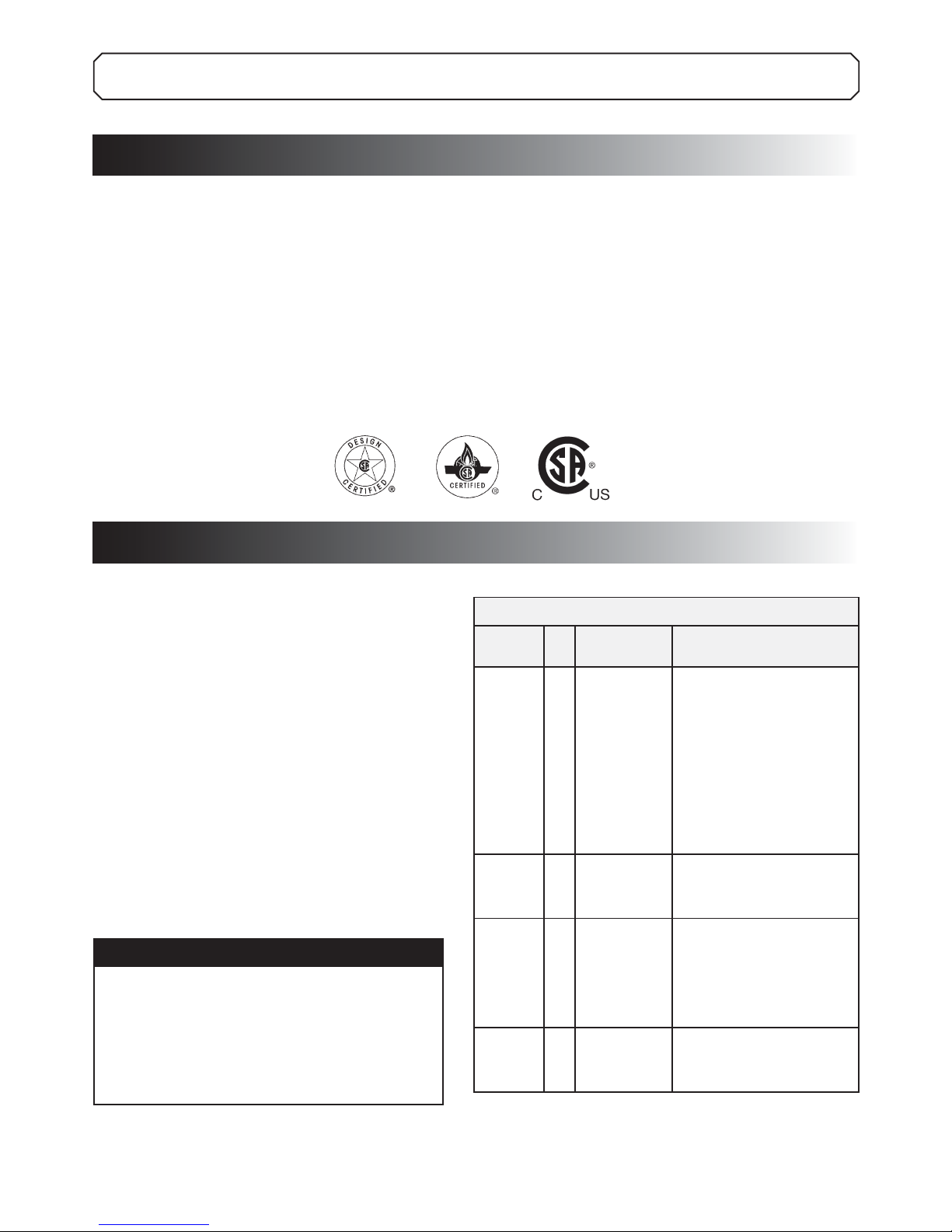
CERTIFICATION AND CODE REQUIREMENTS
This appliance is certifi ed under the latest edition of ANSI Z21.19•CSA 1.4 Refrigerators using gas fuel. The installation
must conform with local codes, or in absence of local codes, the following standards as applicable.
In the U.S. the installation must conform with:
National Fuel Gas Code, ANSI Z223.1/NFPA 54 •
(latest edition).
Recreational Vehicles Code, ANSI A119.2 (latest edition).•
Manufactured Home Construction and Safety Standard, Title •
24 CFR, Part 3280.
If an external electrical source is utilized, the refrigerator, when
installed, must be electrically grounded in accordance with
local codes or, in the absence of local codes, the National Electrical Code, ANSI/NFPA 70 - (latest edition).
In CANADA, the installation must conform with:
Natural Gas and Propane Installation Code, CSA B149.1•
CSA Z240 RV Series, Recreational Vehicles.•
Current CSA Z240.4, Gas-equipped Recreational Vehicles •
and Mobile Housing.
If an external electrical source is utilized, the refrigerator,
when installed, must be electrically grounded in accordance
with local codes or, in the absence of local codes, the Canadian
Electrical Code, CSA C22.1, Parts I and II - (latest edition).
VENTILATION REQUIREMENTS
GENERAL INFORMATION
Ventilation is one of the requirements for proper cooling unit
operation. The installation should be made in such a manner as
to separate the combustion system from the living space of the
mobile home or recreational vehicle. Openings for air supply
or for venting of combustion products should have a minimum
dimension of not less than 1/4 inch.
Proper installation requires one lower fresh air intake and
one upper exhaust vent. Certifi ed installations require one
roof vent and one lower side vent. The ventilation kits shown
in this manual have been certifi ed for use with the different
models as displayed in the “Certifi ed Vent System Kits” table.
The ventilation kits must be installed and used without
modifi cation! An opening toward the outside at fl oor level
in the refrigerator compartment has to be provided for
ventilation of heavier-than-air fuel gases. The lower vent
of the recommended kits is provided with proper size
openings. The fl ow of combustion and ventilating air must
not be obstructed.
CAUTION
It is of especially importance that the airfl ow
around the burner housing, the boiler insulation and the fl ow of combustion gases must not
be obstructed. Items placed in the vicinity of the
refrigerator compartment accordingly must be
secured away from the refrigerator tubing and
fl ue.
The lower side vent is fi tted with a panel, which provides
an adequate access opening for ready serviceability of the
burner and control manifold of the refrigerator. This should
be centered on the back of the refrigerator.
Certifi ed Vent System Kits
Model
RM2351
RM2354
RM2451
RM2454
RM2551
RM2554
DM2652
DM2662
DM2663
DM2852
DM2862
DM3862
NDM1062
NDR1292 5A Roof Base
* Replace “XXX” with the color code numbers. For color codes,
contact your supplier.
** Alternate instructions forwarded with the Ventilator Kit.
For further information, contact your dealer or distributor.
- 3 -
Kit
Components Part no.
No.
2A3ARoof Base
Roof Cover
Lower Side Vent
Lower Side Vent
Upper Side Vent
Lower Side Vent
Power Vent Ass’y
Upper Side Vent
Upper Side Vent
Lower Side Vent
Lower Side Vent
3A Roof Base
Roof Cover
Lower Side Vent
4A Roof Base
Roof Cover
Lower Side Vent
Roof Cover
Lower Side Vent
Power Vent Ass’y
3103633.XXX* or 3310893.XXX*
3103634.XXX* or 3310894.XXX*
3109350.XXX*
RM183
RM123A
RM183
3108705.751**
RM123A
3109492.003
RM183
3109492.003
3103633.XXX* or 3310893.XXX*
3103634.XXX* or 3310894.XXX*
3109350.XXX*
3103633.XXX* or 3310893.XXX*
3103634.XXX* or 3310894.XXX*
3109350.XXX*
3103633.XXX* or 3310893.XXX*
3103634.XXX* or 3310894.XXX*
3103649.XXX*
3108705.744**
Page 4
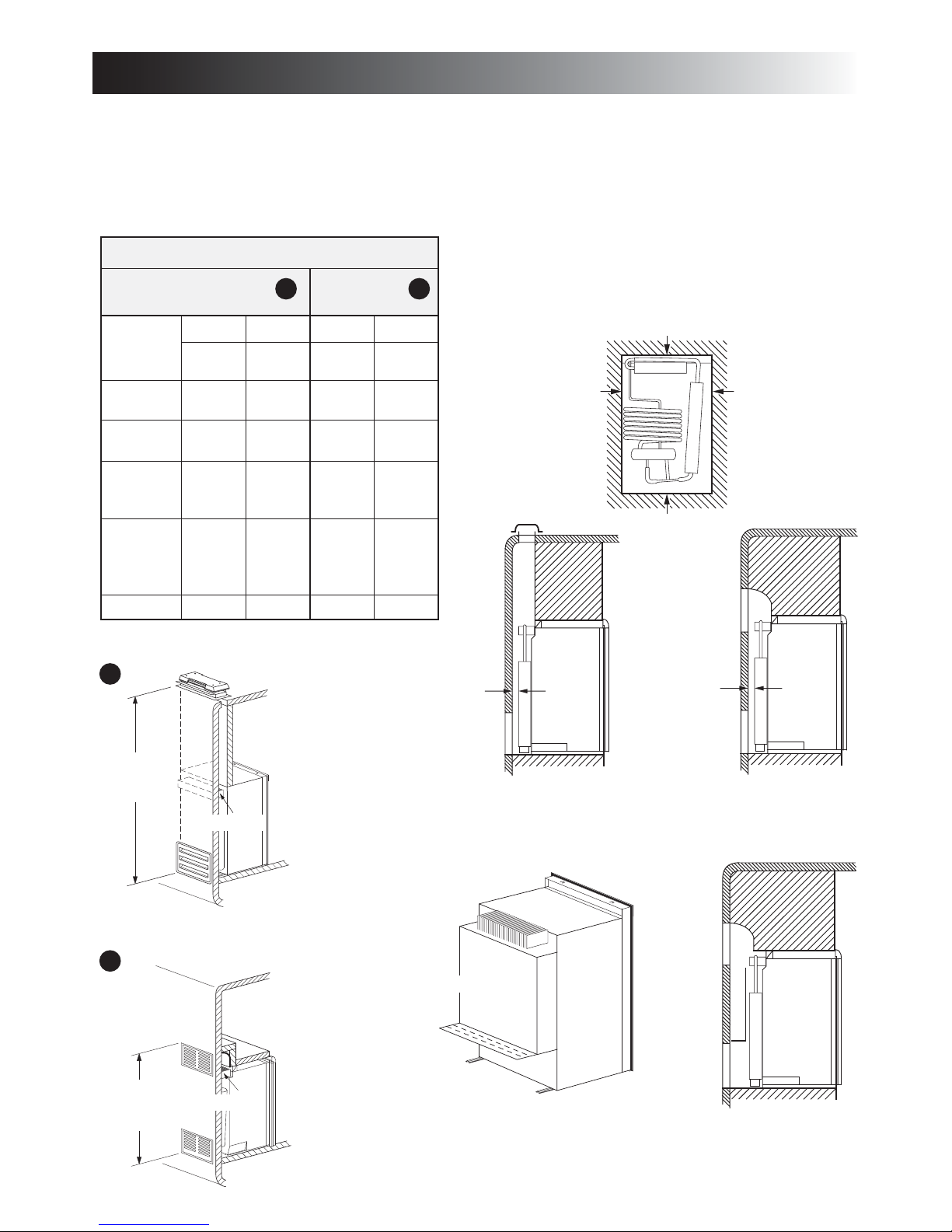
VENTILATION REQUIREMENTS
VENTILATION HEIGHTS
It is essential that all maximum or minimum dimensions
are strictly maintained, as the performance of the refrigerator
is dependent on adequate fl ow of air over the rear of
the refrigerator.
Minimum ventilation heights
Roof vent and
lower side vent
inches mm inches mm
RM2351
RM2354
RM2451
RM2454
RM2551
RM2554
DM2652
DM2662
DM2663
DM2852
DM2862
DM3862
NDM1062
NDR1292 65 1651
31 787 34 864
37-3/4 960
44-1/2 1130
57-3/4 1465
63-3/4 1620
Upper and lower
A
side vent
B
CLEARANCES
Minimum clearances (in inches) to combustible materials:
Top (G) 0
Side (K) 0
Bottom (L) 0
1
Rear (M
1
The distance between the rearmost part of the refrigerator and the wall
behind it.
) 0 / 1 (RM2351 & RM2354)
G
KK
L
A
Minimum
ventilation
height
B
Minimum
ventilation
height
Condenser
Condenser
The upper vent
should be centered
over the condenser
coil at the back of
the refrigerator.
Air channel
M
M
SIDE VIEW WITH DUCT SYSTEM
DM2852, DM2862, DM3862 & NDM1062
For installation instructions of the Air Channel, please refer to
INSTALLATION OF AIR CHANNEL”, Rev. 825129100 or later.
“
- 4 -
Page 5

VENTILATION REQUIREMENTS
OVERALL AND RECESS DIMENSIONS
Dimensions
Model
RM2351
RM2354
RM2451
RM2454
RM2551
RM2554
DM2652
DM2662
DM2663
DM2852
DM2862
DM3862
NDM1062
inches
inches
inches
inches
inches
inches
mm
mm
mm
mm
mm
mm
Overall Recess
Height A Width B Depth C Height H Width W Depth D
30-5/32 21-7/8 22-22/32 29-3/4 20-1/2 21-3/8
766 556 577 756 521 542
37-3/8 24-7/8 24-11/16 39-9/16 23-11/16 24
948 632 627 928 602 610
43-1/2 24-7/8 24-11/16 42-5/8 23-11/16 24
1104 632 627 1083 602 610
54-21/32 24-7/8 26-1/32 53-3/4 23-11/16 24
1388 632 661 1365 602 610
60-51/64 24-7/8 26-1/32 59-15/16 23-11/16 24
1544 632 661 1522 602 610
60-54/64 24-7/8 26-5/8 59-15/16 23-11/16 24*
1544 632 676 1522 602 610*
NDR1292
inches
mm
* Add 1" (25 mm) depth for units with one or two optional ventilator fans.
59-31/32 33-11/16 26-21/32 59-1/16 32-3/4 24*
1523 855 677 1500 832 610*
Side view
$
(
!
View from above
#
$
"
7
General view. Features may vary according to model.
- 5 -
Page 6
7OODSTRIP
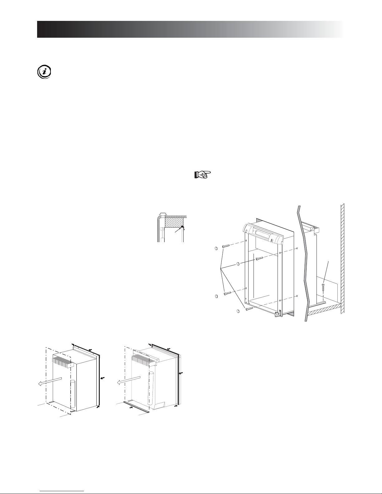
INSTALLATION PROCEDURE
INSTALLING THE REFRIGERATOR
Be careful when installing the refrigerator models
NDM1062 & NDR1292. These are equipped with the
latest vacuum insulated panel technology. The insulating panels are located on the top, back, bottom,
sides and doors. If the surface is punctured, loss of
insulation will occur, resulting in poor refrigerator
performance.
For a proper installation, follow these instructions:
Make sure the fl oor is solid and level. •
The refrigerator must be level and installed in a substantial •
enclosure.
Do not install the appliance directly on carpeting. Carpet-•
ing must be removed or protected by a metal or wood panel
beneath the appliance, which extends at least full width and
depth of the appliance.
RM2451, RM2454, RM2551, RM2554, DM2652, •
DM2662, DM2663, DM2852, DM2862, DM3862,
NDM1062 & NDR1292
A wood strip must be in place across the up-
per opening of the enclosure. The top frame
of the refrigerator will be anchored to the
wood strip with screws.
When installing the refrigerator in the enclosure, all areas •
within the recess have to be sealed. Verify that there is a
complete seal between the front frame of the refrigerator and
the top, sides and bottom of the enclosure. A length of sealing strip is applied to the rear surface of the front frame for
this purpose. The sealing strip should provide a complete
isolation of the appliance’s combustion system from the
vehicle interior.
RM2351 and RM2354: Apply a sealing strip to the foremost
fl oor of the enclosure.
SECURING THE REFRIGERATOR
It is important to follow the sequence in securing refrigerator
in enclosure since failure in doing so can cause leakage between the frame and cabinet. Any space between the counter,
storage area or ceiling and top of the refrigerator greater than
1 1/2 inches should be blocked. The heat produced at the rear
of the refrigerator will become trapped in this space, making
the top of the refrigerator hot and reduce the effi ciency of the
refrigerator.
After the refrigerator is put in place (ensuring a combustion
seal at the front frame), the refrigerator is to be secured in the
enclosure with screws (not included).
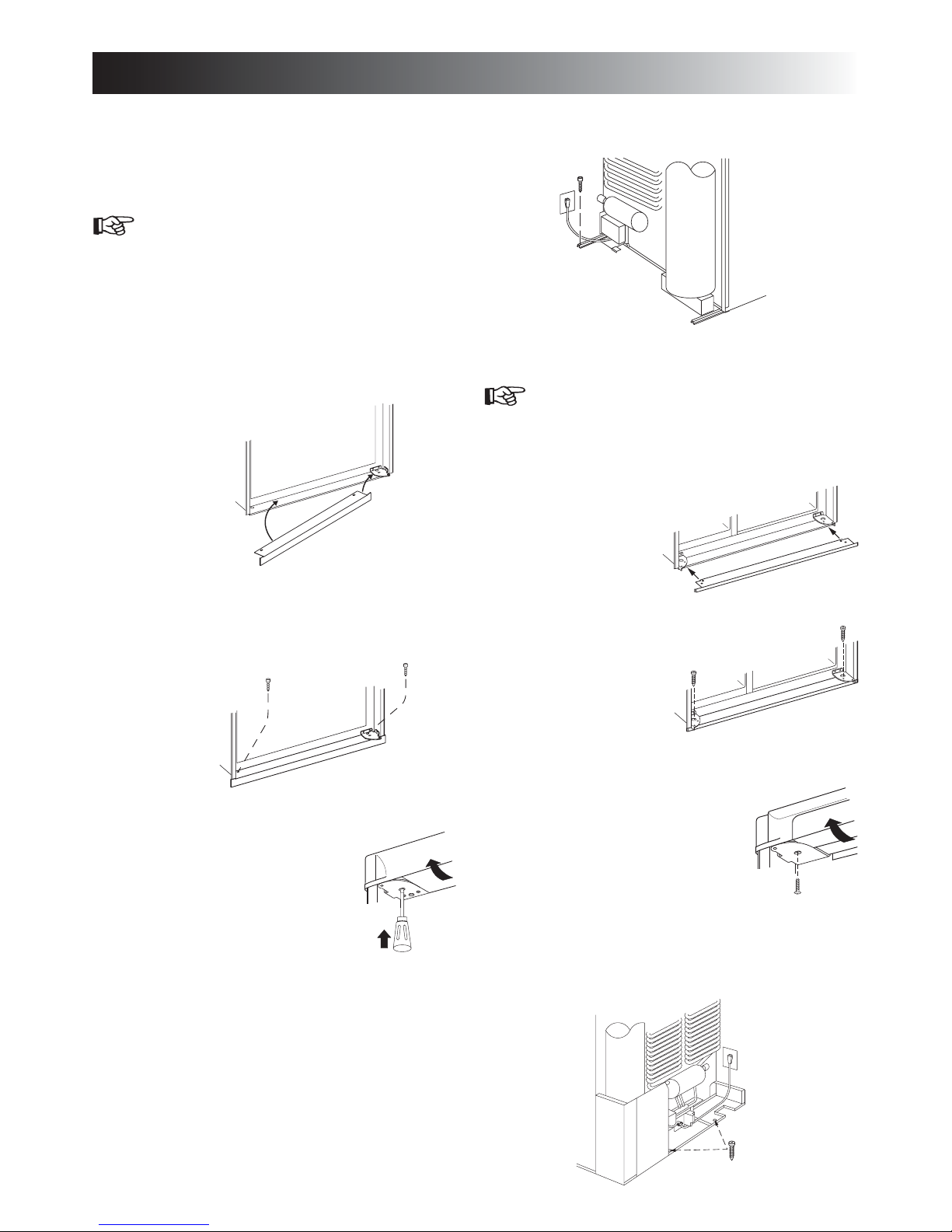
RM2351 & RM2354
Install the fi ve screws in the following order:
Four screws installed through the front frame.1.
(To cover the screw heads, use the plugs in the parts
bag.)
One screw installed in the rear base. 2.
2
1
Be careful not to damage the sealing strip when the
refrigerator is put in place!
RM2351& RM2354RM2451, RM2454, RM2551,
RM2554, DM2652, DM2662,
DM2663, DM2852, DM2862,
DM3862, NDM1062 & NDR1292
General view. Features may vary according to model.
- 6 -
Page 7
INSTALLATION PROCEDURE
RM2451, RM2454, RM2551, RM2554, DM2652,
DM2662, DM2663, DM2852, DM2862, DM3862 &
NDM1062
Install the screws in the following order:
T wo screws installed through the front base. 1.
(Installation of the lower front strip.)
The refrigerator is provided with a lower front strip
(shipped as a loose part). Attach the front strip after
the refrigerator is set into the cutout opening.
Install the lower front strip by sliding it under the a)
bottom hinge plate. The hinge plate can be on the
right or left side depending on the door swing.
Once the lower front strip is slipped under the
hinge, the part is possible to swing into place.
Secure the refrigerator and the lower front strip b)
with two screws: One screw through the hinge and
on the opposite side and then, one screw through
the lower front strip.
One screw installed in the rear base. 3.
NDR1292
Install the screws in the following order:
T wo screws installed through the front base. 1.
(Installation of the lower front strip.)
The refrigerator is provided with a lower front strip
(shipped as a loose part). Attach the front strip after
the refrigerator is set into the cutout opening.
Install the a)
lower front
strip by sliding it under
the bottom
hinge plate.
Secure the b)
refrigerator and
the lower front
strip with two
screws: One
screw through
each hinge.
T wo screws installed in the top frame.2.
Open the door. Gently push the a)
tabs out of the hole in the hinge
with a fl at blade screwdriver
(both sides).
Carefully tilt the top decoration b)
panel and lift to remove from
top frame. Be careful not to
damage the circuit board and wires.
Install the two screws in the top frame, the holes c)
are accessible from underneath.
Seal the opening for the screws with aluminum d)
tape.
Replace the top decoration panel. Be careful not e)
to pinch the wires behind the panel. Make sure the
tabs snap back into the holes in the hinge plate.
Screws installed in the top frame.2.
Open the doors and remove a)
the four screws that secure the
top decoration panel to the
top frame. Two screws are accessible from underneath and
2
1
- 7 -
two are located on each side of
the lock retainer securing the
decoration panel to the front frame. Save screws
for reinstallation of the top decoration panel.
See step 2, b-e in the previous instruction.b)
T wo screws installed in the rear base.3.
Page 8

INSTALLATION PROCEDURE
DRAIN WATER HOSE
Drill a hole through fl ooring. To avoid damage to the hose,
the hole must be positioned so that the hose doesn’t touch the
boiler casing. Seal around the hose that goes through the drilled
hole and ensure that it does not kink when run through the
fl oor. Check to make sure that the supplied hose is long enough
in order for the water to drain outside of the vehicle. If not, the
installer will have to supply the extra length of hose.
RM2351 & RM2354
Boiler
casing
Hose
Hole for drain
water hose
RM2451, RM2454, RM2551, RM2554, DM2652, DM2662,
DM2663, DM2852, DM2862, DM3862 & NDM1062
CONNECTIONS
Gas connection
Hook up to the gas supply line is accomplished at the manual
gas valve, which is furnished with a 3/8” SAE (UNF 5/8” -18)
male fl are connection. All completed connections should be
examined for leaks using a solution of liquid detergent and
water.
WARNING
!
6
EXPLOSION HAZARD. Never use an open
fl ame to check for gas leaks. Failure to heed this
warning could cause an explosion resulting in
death or severe personal injury.
The gas supply system must incorporate a pressure regulator
to maintain a supply pressure of not more than 11 inches water
column. When testing the gas supply system at test pressures:
> 1/2 psi• - the refrigerator and its individual shutoff valve
must be disconnected from the gas supply piping system.
1/2 psi • - the appliance must be isolated from the gas
supply piping system by closing its individual manual shutoff valve.
If detailed instructions on the installation and connection to
the gas supply are required, please contact your dealer or
distributor.
NDR1292
Hole for drain
water hose
Boiler
casing
Hose
Boiler
casing
Hose
Hole for drain
water hose
Drill the hole in the
cut out opening of
the base plate
Testing LP gas safety shut off
The gas safety shut off must be tested after the refrigerator is
connected to LP gas supply.
RM2354, RM2454, RM2554, DM2662, DM2663,
DM2862, DM3862, NDM1062 & NDR1292
To test the gas safety shut off, follow these steps:
Start the refrigerator. Switch to GAS mode. 1.
Check that the gas fl ame is lit and the GAS mode 2.
indicator lamp is on.
Close the manual gas shutoff valve at the back of the 3.
refrigerator.
Wait for approx. 6 minutes. The CHECK indicator 4.
lamp should be lit and the GAS mode indicator lamp
should be off.
Remove the protection cover. 5.
Open the manual gas shutoff valve. Do not change 6.
any button positions on the control panel.
Apply a non corrosive commercial bubble solution 7.
to the burner jet orifi ce. No bubbles should appear at
the opening of the burner jet orifi ce. The presence of
bubbles indicates a defective gas safety shutoff, and
service is required.
If no bubbles are present at the burner jet orifi ce, 8.
rinse it with fresh water. Be careful not to damage the
burner jet orifi ce.
- 8 -
Page 9
INSTALLATION PROCEDURE
Put back the cover. 9.
Press the ON/OFF button off and then back on. Nor-10.
mal operation of the burner should return.
Allow the burner to operate for a minimum of fi ve 11.
minutes.
RM2351, RM2451, RM2551, DM2652 & DM2852
To test the gas safety shut off, follow these steps:
Start the refrigerator without connecting to 1.
120V AC.
Check that the gas fl ame is lit. In AUTO mode, 2.
the AUTO mode indicator lamp is on.
Follow steps 3-11 in the previous instruction. 3.
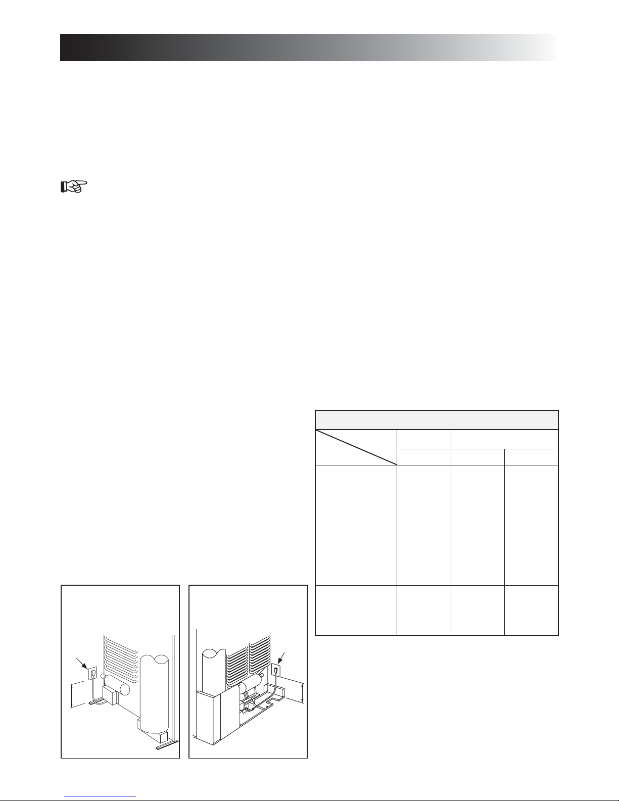
Electrical connection
120 V AC connection
The refrigerator is equipped with a grounded three-prong plug
for protection against shock hazards. It should be plugged di-
rectly into a properly grounded three-prong receptacle. Do not
cut or remove the grounding prong from this plug!
The free length of the cord is 2 feet. It should be routed to
avoid direct contact with the burner cover, fl ue cover or any
other components that could damage the cord insulation.
To allow easy access through the vent door, it is recommended
that the receptacle is placed like this:
RM2351 & RM2354•
To the left of the refrigerator and 4-6” above the refrigerator
mounting fl oor
RM2451, RM2454, RM2551, RM2554, DM2652 & •
DM2852
To the left of the refrigerator and 6” above the refrigerator
mounting fl oor
DM2662, DM2663, DM2862, DM3862 & NDM1062•
To the left of the refrigerator and 3” above the refrigerator
mounting fl oor.
NDR1292•
To the right of the refrigerator and 10” above the refrigerator
mounting fl oor.
12V DC connection
RM2451, RM2551, DM2652 & DM2852: These refrigerator
models are not designed for 12V DC operation of the cooling
system. However, 12V DC must be supplied to operate the
controls.
RM2354, RM2454, RM2554, DM2662, DM2663, DM2862,
DM3862 & NDM1062: These refrigerator models require a
continuous 12V DC supply to maintain the automatic energy
system.
The connection is made to the positive (+) and negative (-)
terminals of the terminal block on back of the refrigerator.
Correct polarity must be observed when connecting to the DC
supply. Do not use the chassis or vehicle frame as one of the
conductors. Connect two wires at the refrigerator and route to
the DC supply. Ensure the connections are clean, tight and free
from corrosion.
Ensure that the wires from the battery to the refrigerator are
able to handle the load. The distance the current must travel
from the battery to the refrigerator dictates the AWG wire size
to be used. Inadequate wire sizes can result in a voltage drop
which affects the refrigerator performance.
For 3-way models, the voltage drop affects the wattage output
of the 12V cartridge heater and the refrigerator performance.
The 12V DC heater is fused with a 30 amp. in-line blade fuse.
Recommended wire sizes are displayed in the following table:
MAXIMUM TOTAL CONDUCTOR WIRE LENGTH
WIRE
MODEL
RM2351
RM2451
RM2551
DM2652
DM2662
DM2852
DM2862
DM3862
NDM1062
NDR1292
Size Length
AWG
14
12
ft m
17
27
5
8
RM2451, RM2454, RM2551,
RM2554, DM2652, DM2662,
DM2663, DM2852, DM2862,
DM3862 & NDM1062
120V AC
receptacle
olt AC
tacle
3”
4-6”
6”
NDR1292
120V AC
receptacle
10”
- 9 -
RM2354
RM2454
RM2554
DM2663
10
17
8
27
5
8
Page 10
DOOR MOUNTING INSTRUCTIONS
REVERSING THE DOOR SWING
For all models, except NDR1292, the refrigerators are equipped
with hinges that makes it possible to change the direction the
door opens by moving the hinges to the opposite side. A special
hinge kit must be used in order to change the door swing.
For conversion kit number, see
APPENDIX A - SPARE PARTS.
For additional information, please contact service point or
distributor service dept. for assistance.
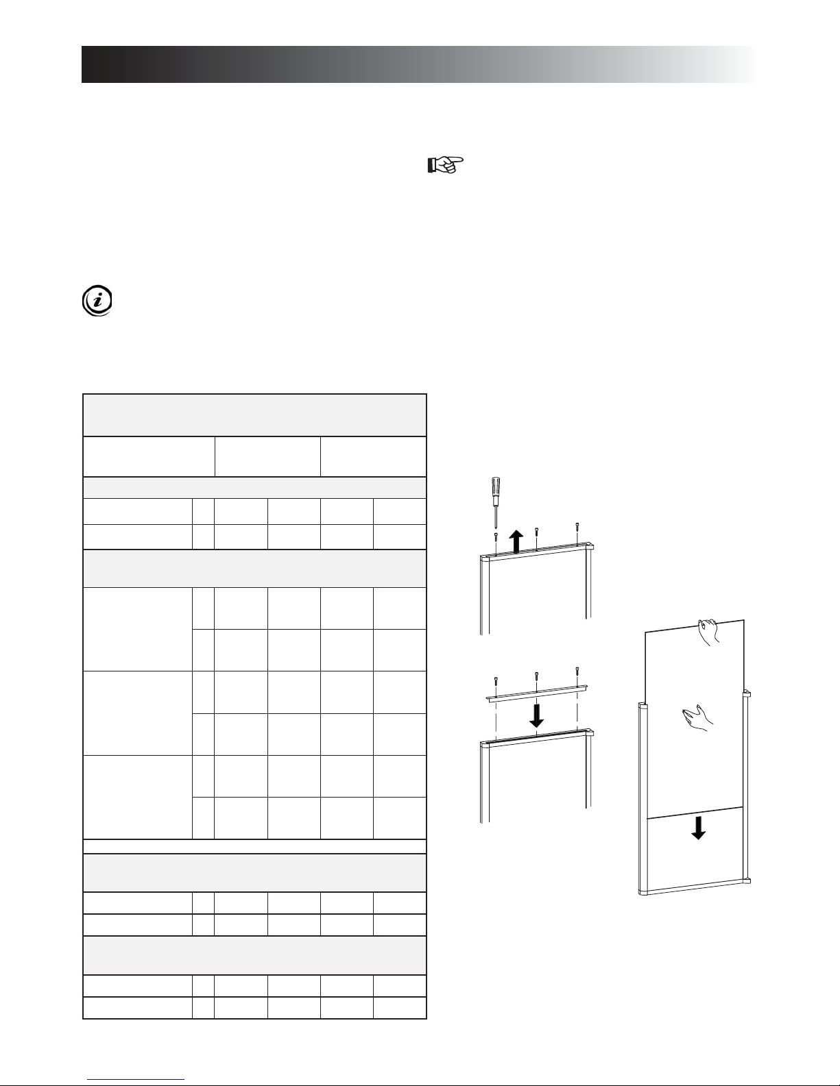
MOUNTING THE DOOR PANEL(S)
Optional door insert panels are available for all
models except NDR1292. The refrigerator is normally delivered without door panel(s).
Before starting the mounting work, read this instruction thoroughly and check that the panel dimensions are in compliance
with those given in the following table:
PANEL DIMENSIONS
max. thickness 5/32" (4 mm)
Width
max min
UPPER
LOWER /SINGLE
DOOR
Height
max min
mm
403 401 527 524
inch
15-27/32 15-25/32 20-3/4 20-5/8
With screws
To mount the panel, follow these steps:
Open the door 90 degrees. 1.
On new refrigerators, the decoration strip is taped 2.
inside the door; if installed on the door, remove
the door decoration strip (2) by removing its three
screws (1).
NDR1292:
Fresh food compartment door - remove three screws.
Freezer compartment door - remove two screws.
Insert the vertical edges into the grooves of the door 3.
frame (3).
Push the panel downwards so that the lower 4.
horizontal edge of the panel (4) is fi tted into the bottom grove (5).
Put the decoration strip across the door so that the 5.
gap is covered. Secure the decoration strip with the
screws removed in step 2.
1
1
1
2
RM2351
RM2354
RM2451
RM2454
667 665 498 496
mm
26-17/64 26-3/16 19-5/8 19-17/32
inch
827 825 527 524
mm
DM2652
DM2662
DM2663
RM2551
RM2554
32-9/16 32-1/2 20-3/4 20-5/8
inch
983 981 527 524
mm
DM2852
DM2862
NDM1062
38-11/16 38-5/8 20-3/4 20-5/8
inch
FROZEN FOOD
COMPARTMENT
mm
NDR1292
1402 1400 288 265
inch
55-3/16 55-1/8 10-9/16 10-7/16
FRESH FOOD COMPARTMENT
mm
NDR1292
1402 1400 430 427
inch
55-3/16 55-1/8 16-15/16 16-13/16
1
1
1
3
3
4
5
- 10 -
Page 11
DOOR MOUNTING INSTRUCTIONS
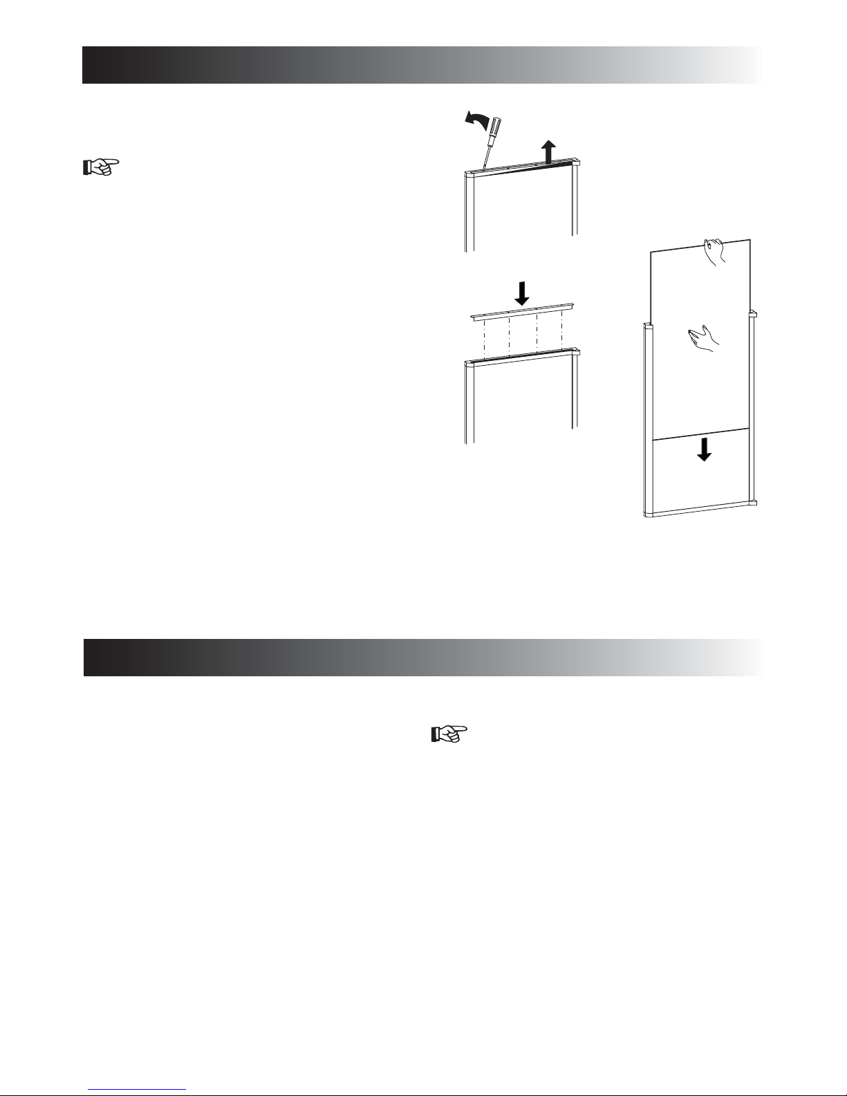
Snap in
To mount the panel, follow these steps:
Open the door 90 degrees. 1.
On new refrigerators, the decoration strip are 2.
taped inside the door; if installed on the door,
remove the door decoration strip (2) by gently
pushing the four tabs away with a fl at blade
screwdriver (1).
Insert the vertical edges into the grooves of the 3.
door frame (3).
Push the panel downwards so that the lower 4.
horizontal edge of the panel (4) is fi tted into the
bottom grove (5).
Snap in the decoration strip (2). 5.
1
2
2
3
4
5
3
REFRIGERATOR REMOVAL
Before removing the refrigerator:
Verify that the AC and DC voltage leads are disconnected. •
Shut off the gas supply. •
Disconnect the gas supply line at the rear of the refrigerator.•
Always use a back up wrench when loosening and tightening connections.
To remove the refrigerator, follow these steps:
Cap the gas supply line.1.
Loosen the screws anchoring the refrigerator to the 2.
enclosure.
Slide the refrigerator out of the compartment.3.
Replacement is the reverse of removal. When reinstalling the
refrigerator, make sure the sealing strips are properly positioned. Check all connections for gas leaks.
- 11 -
Page 12
OPERATING INSTRUCTIONS
REFRIGERATOR OVERVIEW
ABSORPTION COOLING SYSTEM
In an absorption refrigerator system, ammonia is liquefi ed in
the fi nned condenser coil at the top rear of the refrigerator.
The liquid ammonia then fl ows into the evaporator (inside the
freezer section) and is exposed to a circulating fl ow of hydrogen gas, which causes the ammonia to evaporate, creating a
cold condition in the freezer.
When starting this refrigerator for the very fi rst
time, the cooling cycle may require up to four
hours of running time before the cooling unit is
fully operational.
The tubing in the evaporator section is specifi cally sloped to
provide a continuous movement of liquid ammonia, fl owing
downward by gravity through this section.
Sodium chromate is used for corrosion protection (less than
2 weight % of the coolant).
Leveling the refrigerator
Leveling is one of the requirements for proper operation with
absorption refrigerators. to ensure proper leveling the vehicle
needs to be leveled only so it is comfortable to live in (no noticeable sloping of fl oor or walls).
Any time the vehicle is parked for several hours with the refrigerator operating, the vehicle should be leveled to prevent this
loss of cooling.
If the refrigerator is operated when it is not level and the
vehicle is not moving, liquid ammonia will accumulate in sections of the evaporator tubing. This will slow the circulation
of hydrogen and ammonia gas, or in severe cases, completely
block it, resulting in a loss of cooling.
When the vehicle is moving, the leveling is not critical, as the
rolling and pitching movement of the vehicle will pass to either
side of level, keeping the liquid ammonia from accumulating in
the evaporator tubing.
MODES OF OPERATION
AUTO mode - AES/AUTO mode
When operating in AUTO - AES/AUTO mode, the AUTO AES/AUTO mode indicator lamp is illuminated. The control system will automatically select between AC and GAS operation.
AC has priority over GAS. Should AC become unavailable, the
system automatically switches to GAS. As soon as AC becomes
available again, the control will switch back to AC regardless
of the status of the GAS operation.
If the CHECK indicator lamp is illuminated the controls have
failed to ignite the burner in the GAS mode. To restart an ignition attempt with the CHECK lamp illuminated (or to turn off
the CHECK lamp), press the ON/OFF button OFF and back
ON again. The control system activates the ignition system and
makes three attempts to light the burner for a period of approx.
45 sec. at two minutes interval. Should 120 V AC become
available while the CHECK indicator lamp is on, the CHECK
lamp will not turn off until the ON/OFF button is pressed OFF
and then ON again.
GAS mode
RM2351, RM2451, RM2551, DM2652 & DM2852:
When operating in GAS mode, the AUTO mode
indicator lamp will be off.
RM2354, RM2454, RM2554, DM2662, DM2663, DM2862,
DM3862, NDM1062 & NDR1292: When operating in GAS
mode, the GAS mode indictor lamp is illuminated.
This mode provides LP gas only. The control system activates
the ignition system and attempts to light the burner for a period
of approx. 45 sec. at two minutes interval. If unsuccessful, the
CHECK indicator lamp will illuminate.
To restart GAS operation, press the ON/OFF button to OFF
and then back ON. The control system attempts a new ignition
sequence.
AUTOMATIC ENERGY SELECTOR SYSTEM
The refrigerator is equipped with an automatic energy selector
system. The user turns the refrigerator on and then, the refrigerator automatically selects the most suitable energy source available, either 120 V AC or LP gas operation. The system can be
set by the user to be fully automatic (AUTO mode is selected)
or to operate on LP gas only (AUTO mode is off).
On 3-way models, the control system can manually be set to
DC mode (DC operation). The DC mode overrides all other
operating modes.
The refrigerator controls will work down to 9.6 V DC.
Purging air from the lines
If the refrigerator has not been used for a long time - or the LP tanks have just been refi lled, air may be trapped in the
supply lines. To purge the air from the lines, turn the refrigerator off and on by pressing the ON/OFF button. If the fl ame is
not lit within 45 seconds, turn the refrigerator off and back on
again. This procedure can be repeated 3 to 4 times. If repeated
attempts fail to start the LP gas operation, check to make sure
that the LP gas supply tanks are not empty and that all manual
shutoff valves in the lines are open.
WARNING
!
6
FIRE OR EXPLOSION HAZARD. When refueling or parked near gasoline pumps, shut off all
LP gas appliances. Failure to heed this warning
could cause a fi re or explosion resulting in death
or severe personal injury.
- 12 -
Page 13

RM2354, RM2454, RM2554 & DM2663
RM2351, RM2451, RM2551, DM2652 & DM2852
RM2354, RM2454, RM2554, DM2662, DM2663, DM2862,
DM3862, NDM1062 & NDR1292
DM2652, DM2662, DM2663,DM2852,DM2862,DM3862,
NDM1062 & NDR1292
DM3862, NDM1062 & NDR1292
RM2354, DM2662, DM2663, DM2862, DM3862, NDM1062 &
NDR1292
REFRIGERATOR OVERVIEW
DC mode
RM2354, RM2454, RM2554 & DM2663
When operating in DC mode (3-way models only), the DC
mode indicator lamp is illuminated and all other lamps are off.
To select another operating mode, turn off the DC mode by
pressing the DC selector button. The DC lamp is turned off.
When there is no charging of the house battery, switch to
AUTO mode or GAS mode since running the refrigerator on
12 V DC will quickly drain the battery.
LIMP MODE OF OPERATION
In the event of a failure of a major operating component, the
control system will continue to operate the cooling system.
RM2351, RM2451, RM2551, DM2652 & DM2852
If the control can not read the temperature sensor and control
the preset temperature, the control will run the cooling unit
continuously at the energy source available. The refrigerator
will continue to operate in this mode indefi nitely - or - until a
new sensor is installed and the system reset.
RM2354, RM2454, RM2554, DM2662, DM2663, DM2862,
DM3862, NDM1062 & NDR1292
Two modes of operation can occur:
The fi rst limp mode of operation will execute if the display 1)
module becomes non functional. The control system reverts
to full automatic operation selecting the best energy source
available with AC, DC (3-way only) and GAS priority. The
temperature setting is maintained at the mid position. The
power module will continually attempt to reestablish operation of the display module.
The second limp mode of operation will execute when 2)
a failure of the temperature sensing device or associated
electronic circuitry occurs. If this should happen, the control system operates on the energy source selected via the
control panel. The cooling unit runs continuously on the selected energy source. The refrigerator continues to operate
in this mode indefi nitely or until a new sensor is installed
and the system is reset.
CLIMATE CONTROL SYSTEM
DM2652, DM2662, DM2663, DM2852, DM2862, DM3862,
NDM1062 & NDR1292
During the summer months of high temperatures and humidity,
the metal frame between the freezer and fresh food compartments may have water droplets forming. The number of water
droplets will increase if the vehicle is not air conditioned during these months. The refrigerator comes standard with a 12 V
DC climate control that will evaporate the water droplets when
they form. The climate control can be left on continuously or
used only when temperatures require it. Note that when turned
on, the climate control will draw 12 V DC power continuously.
Turn it off when a charging source is not available.
LOW AMBIENT CONTROL
DM3862, NDM1062 & NDR1292
The refrigerator is equipped with an exclusive feature that
allows for trouble-free operation in low ambient temperature
(like below 50°F) for extended periods of time. Once the outdoor temperature is above 50°F, the low ambient switch should
be turned off.
THERMOSTAT
RM2354, DM2662, DM2663, DM2862, DM3862, NDM1062 &
NDR1292
The thermostat controls both the gas and electric operation,
thereby eliminating the necessity of resetting each time a different energy source is employed. After the initial start-up,
the thermostat should be adjusted to the desired temperature
setting.
CONTROL PANEL
RM2351, RM2451, RM2551, DM2652 & DM2852
AB
AUTO
ON
12
OFF
CHECK
GAS
AUTOMATIC REFRIGERATOR TEMPERATURE CONTROL
- 13 -
ON/OFF 1. button (main power)
AUTO/GAS2. mode selector button
AUTOA. mode indicator lamp
CHECKB. indicator lamp
(GAS mode only)
Page 14

REFRIGERATOR OVERVIEW
RM2354, RM2454, RM2554 & DM2663
AD E
DC
ON
AUTO
123 4
OFF
GAS
AC
B
CF
CHECK
DM2662, DM2862 & NDM1062
AD
ON
OFF
BC
AC
AUTO
21
GAS
CHECK
COLD
COLD
ON/OFF1. button (main power)
DC2. mode selector button
AUTO/GAS 3. mode selector button
3
1
2
COLDEST
4
5
Temperature4. selector button
DCA. mode indicator lamp
ACB. mode indicator lamp
GASC. mode indicator lamp
AUTOD. mode indicator lamp
CHECKE. indicator lamp
(GAS mode only)
Temperature F. indicator lamps
ON/OFF1. button (main power)
AUTO/GAS2. mode selector button
Temperature3. selector button
3
1
2
COLDEST
4
5
3
AUTOA. mode indicator lamp
ACB. mode indicator lamp
GASC. mode indicator lamp
CHECKD. indicator lamp
E
TemperatureE. indicator lamps
DM3862, NDM1062 & NDR1292
B
AES
ON
12 3 4 5
OFF
AUTO
AC
GAS
AC GEF
CHECK
D
COLD
1
COLDEST
5
3
2
4
CLC
NDR1292
ON
1
OFF
B
AES
AUTO
2
GAS
AC
C
A
CHECK
D
1
COLD
2345 COLDEST
E
ON/OFF1. button (main power)
AES/AUTO/GAS2. mode
selector button
LAC
Temperature3. selector button
Climate control4. button
Low ambient control5. button
ACA. mode indicator lamp
AES/AUTO B. mode indicator lamp
GASC. mode indicator lamp
CHECKD. indicator lamp
Temperature E. indicator lamps
Climate controlF. indicator lamp
Low ambientG. control indicator lamp
ON/OFF1. button (main power)
AES/AUTO/GAS 2. mode
selector button
Temperature3. selector button
3
ACA. mode indicator lamp
AES/GASB. mode indicator lamp
GASC. mode indicator lamp
CHECKD. indicator lamp
TemperatureE. indicator lamps
- 14 -
Page 15

DM2652, DM2662, DM2663, DM2852, DM2862, NDM1062 &
NDR1292
DM3862, NDM1062 & NDR1292
NDM1062 & NDR1292
DM3862, NDM1062 & NDR1292
C
CLC
INSTRUCTIONS FOR USE
STARTUP
WARNING
!
6
FIRE HAZARD. Before lighting the gas burner,
after that the RV has not been used for some
time, please check that the gas path between
the burner jet and the burner tube has not been
obstructed. Failure to heed this warning could
cause a fi re resulting in personal injury.
BURNER MOUNTING
SCREWS
BURNER TUBE .
SPARK ELECTRODE
BURNER JET
Before starting the refrigerator:
Check that all the manual gas valves are in the ON position. •
Make sure that a continuous 12V DC supply is available for •
the electronic control to function.
SOLENOID VALVE
MANUAL SHUT OFF VALVE
(Shown in open position)
PRESSURE TEST PORT
INLET FITTING
To turn off
The refrigerator may be shut off while in any mode of operation by pressing the main power ON/OFF button to the OFF
position. This shuts off all DC power to the refrigerator, including the interior light.
If the refrigerator will not be in operation for a period of weeks,
it should be emptied, defrosted, cleaned and the doors left ajar.
The ice trays should also be dried and kept outside the cabinet.
TURNING ON THE CLIMATE CONTROL
DM2652, DM2662, DM2663, DM2852, DM2862, NDM1062 &
NDR1292
Turn the Climate control switch to I (ON).
The Climate control
switch is located beneath
the top decoration panel
that houses the control
panel.
TURNING ON/OFF
To turn on:
Press the ON/OFF button. 1.
Select operation mode:2.
AUTO - AES/AUTO mode• (AC and GAS)
Press the AUTO/GAS - AES/AUTO/GAS mode
selector button (if not already on). The illuminated
lamp indicates the selected mode.
(If the CHECK indicator lamp is illuminated, see
REFRIGERATOR OVERVIEW > MODES OF
OPERATION > AUTO MODE - AES/AUTO MODE for
further information.)
GAS mode (• GAS operation only)
Press the AUTO/GAS - AES/AUTO/GAS mode
selector button to turn off the AUTO mode (if not
already off).
(Within 45 seconds the burner should be ignited
and operating normally. If not, see
TOR OVERVIEW > MODES OF OPERATION > GAS
for further information.)
MODE
DC mode • (3-way models only)
Press the DC mode indicator button. The DC lamp
will be turned on. To select AUTO or GAS mode,
turn off the DC mode by pressing the DC mode selector button. The DC lamp will then be turned off.
If necessary, adjust the thermostat by pressing the 3.
Temperature selector button.
(RM2351, RM2451, RM2551, DM2652 &
DM2852
preset temperature setting.)
: The temperature is controlled by a factory
REFRIGERA-
DM3862, NDM1062 & NDR1292
Press the CLC button. The indicator lamp will
illuminate.
AES
AUTO
ON
OFF
AC
GAS
CHECK
COLD
COLDEST
1
5
3
2
4
TURNING ON THE LOW AMBIENT CONTROL
NDM1062 & NDR1292
Turn the Low ambient control switch to I (ON).
The Low ambient control
switch is located beneath
the top decoration panel
that houses the control
panel.
DM3862, NDM1062 & NDR1292
Press the LAC button. The indicator lamp will
illuminate.
AES
AUTO
ON
OFF
AC
GAS
CHECK
COLD
COLDEST
1
5
3
2
4
CLC
CLC
LAC
LAC
- 15 -
Page 16

INSTRUCTIONS FOR USE
NDM1062
The following information, “USING THE ICE MAKER”, is only
valid for refrigerator model
NDM1062 equipped with ice maker.
USING THE ICE MAKER
How it works
Before the ice maker can operate, make sure that the:
Refrigerator is connected to 120 V AC. •
Water valve supplying the refrigerator is turned on.•
Ice level bail arm is in its fully down position.•
Ice level
bail arm
Down
position
When the ice maker thermostat senses the preset temperature
for the ejection of the ice cubes, the fi ngers will start to rotate,
dumping any ice cubes and fi lling the mold with water. When
the storage container is full, the bail arm will come in contact
with the ice cubes. The bail arm cannot return to the full down
position and the ice production is stopped until the bin is emptied, or ice cubes are removed.
When on the road, the water in the ice maker might, depending
on road conditions, splash out of the mold. To avoid splashing,
the mold needs to be either empty - or - the water in the mold
must be frozen.
Water supply
The water supply system must have a minimum pressure of
15 pounds per square inch gauge (psig). Use a 1/4” diameter
water line to the water valve at the rear of the refrigerator. The
water line must have a manual shutoff valve placed where it is
easily accessible.
The maximum water level is represented by a thin line. It is
essential that the water level does not exceed this line!
Adjusting the size of cubes
The fi rst container of ice cubes should be dumped if the water
system has been winterized or not used for several weeks.
Note that if the ice maker have been cleaned and drained, no
ice cubes will be dumped into the bin during the fi rst cycle.
The fi rst few cycles may produce small cubes due to air trapped
in the water lines. Once the ice maker has run through several
cycles and if the cubes are too small or sticking together, adjustment is necessary on the amount of water entering the mold.
To adjust the size of cubes, follow these steps:
Remove the protective cover from the ice maker 1.
mechanism.
Locate the adjusting screw under the protective 2.
cover.
Adjusting screw
Cover
To increase the size of cubes, turn the screw counter 3.
clockwise. To decrease the cube size or if the cubes
are stuck together, turn the screw clockwise.
NOTE! To prevent overfi lling, DO NOT turn the adjustment
screw more than one revolution at a time. Allow the ice maker
to cycle several times before another adjustment is made. Be
sure to replace the protective cover on the cycle after the adjustments are complete.
Maximum
water level
If necessary change the water fl ow by adjusting the water supply, see the step-by-step instruction in
OF CUBES.
ADJUSTING THE SIZE
- 16 -
Page 17

RM2351, RM2454, RM2554, DM2662, DM2663, DM2862,
DM3862, NDM1062 & NDR1292
STORAGE COMPARTMENTS
REFRIGERATOR VOLUME
MODEL TOTAL REFRIGERATED
VOLUME
RM2351
RM2451
RM2551
DM2652, DM2662
DM2852, DM2862
NDM1062 9.2
NDR1292 12
& RM2354 3
& RM2454 4
& RM2554 5
& DM2663 6
& DM3862 8
WARNING
!
6
(cu.ft)
EXPLOSION HAZARD. Never store explosive
substances in the refrigerator, such as cigarette
lighter fuel, gasoline, ether or the like. Failure
to heed this warning could cause an explosion
resulting in death or severe personal injury.
FOOD STORAGE COMPARTMENT
Cool the refrigerator before placing any food inside. • Never
put hot food or drinks into the refrigerator - cool them fi rst.
T• he food storage compartment is completely closed and
unventilated, which is necessary to maintain the required
low temperature for food storage. Consequently, foods having a strong odor or those that absorb odors easily should be
covered.
Vegetables, salads etc. should be covered to retain their •
crispness.
The coldest positions in the refrigerator are under the cool-•
ing fi ns and at the bottom of the refrigerator. The warmer areas are on the upper door shelves. This should be considered
when placing different types of food in the refrigerator.
Arrange all food in the unit to allow for free air circulation. •
Do not overpack because a stuffed refrigerator must work
harder and will have higher cabinet temperatures.
Do not leave the unit’s door open any longer than necessary. •
This will reduce frost formation and increase the effi ciency
of the refrigerator.
FROZEN FOOD STORAGE COMPARTMENT
This compartment is not designed for deep or quick freezing
of food.
To prevent food from drying out, keep it in covered dishes, •
containers, plastic bags or wrapped in aluminum foil.
Meat or fi sh, whether raw or prepared, can be stored in the •
frozen food storage compartment provided they are precooled fi rst in the refrigerator. They can be stored about
three times longer in the frozen food compartment as compared to the fresh food compartment.
Quick frozen soft fruits and ice cream should be placed in •
the coldest part of the compartment, which is at the bottom
of the aluminum liner.
Frozen vegetables, may be stored in any part of the compart-•
ment.
To prevent frost buildup, which can reduce the effi ciency, •
wipe excess moisture off items being placed in the compartment.
Ice cubes
Ice cubes can be made in the freezer compartment. For faster
ice making, the trays should be placed in direct contact with the
bottom of the freezer compartment.
RM2351, RM2454, RM2554, DM2662, DM2663, DM2862,
DM3862, NDM1062 & NDR1292
Ice will be made more rapidly if f the thermostat is set at its
highest position, but be sure to move the thermostat back
to normal setting when the ice is formed; the refrigerator might
otherwise become too cold.
- 17 -
Page 18

STORAGE COMPARTMENTS
REMOVING AND REPLACING THE SHELVES
1
Put a screwdriver into the slot of the shelf
lock. Turn the screwdriver counter clockwise.
Remove the shelf locks from the wire shelf.
3
2
Slide the wire shelf to the left.
The right-hand side of the shelf will come
loose.
4
Lower the right-hand side of the wire shelf
and let the left-hand side slide out of the holes
in the wall.
5
Slide the shelf into the holes on the righthand side.
Insert the ends of the wire shelf on the
left-hand side at the desired position.
6
Slide the plastic plugs into the holes of the
wall. Snap the shelf locks onto the wire shelf.
- 18 -
Page 19

PRODUCT CARE
NDM1062
DEFROSTING
Shut off the refrigerator by pressing the main power 1.
ON/OFF button (OFF position).
Empty the refrigerator.2.
Leave the cabinet and freezer doors open and place 3.
the drip tray under the fi nned evaporator.
Defrosting time can be reduced by fi lling the ice
trays with hot water and placing them in the freezer
compartment.
Do not use:
A knife or an ice pick, or other sharp •
tools to remove frost from the freezer
shelves. It can create a leak in the ammonia system.
A hot air blower. Permanent damage •
could result from warping the metal or
plastic parts.
When all the frost has melted, dry the interior with a 4.
clean cloth.
Turn the refrigerator back on. 5.
CAUTION
Draining the ice maker
If the RV is in storage and the refrigerator or the DC power is
turned “OFF” there will be no 12V DC present to operate the
heat tape; therefore, it will be necessary to drain and dry the ice
maker. This will prevent water from freezing in the solenoid
valve or becoming stale and producing bad tasting ice.
If the temperatures are expected to reach or exceed 0°F/-18°C
the ice maker must be drained to prevent component damage
and leaks.
NOTE! Water, compressed air and AC power are required to
drain the ice maker. Draining of the ice maker must be done by
a qualifi ed service technician.
To drain the ice maker, follow these steps:
Shut off water supply valve to the ice maker.1.
Place a shallow pan under water solenoid valve.2.
Remove inlet fi tting to ice maker water solenoid 3.
valve. Drain water from the supply line.
Inlet fitting for
water supply line
The following information, “STORAGE PROCEDURE/WINTER-
IZING THE REFRIGERATOR
NDM1062 equipped with ice maker.
model
”, is only valid for refrigerator
STORAGE PROCEDURE/WINTERIZING THE
REFRIGERATOR
The refrigerator is equipped with a heater tape wrapped around
the water solenoid valve and outlet water tube. During cold
weather operation below 32°F/0°C the automatic temperature
switch will turn the heater tape on automatically.
If the RV will not be in use for an extended period of time or
put into storage:
Drain the RV water system.•
Disconnect the water lines from the inlet and outlet sides •
of the water valve. Drain the lines into a cup and allow the
lines to dry.
The ice maker should be drained and dried, see •
THE ICE MAKER
Using a lukewarm soda solution, clean the interior liner of •
the refrigerator. Clean the fi nned evaporator, ice trays and
shelves. Use warm water only and never strong chemicals or
abrasives since these can damage the protective surfaces.
Leave the doors ajar. •
.
DRAINING
Plastic nut
Metal tube
1/4” Water line
to ice maker
Remove the plastic nut and water line from outlet 4.
side of the water solenoid valve. Drain water from
the line.
Connect compressed air onto the inlet fi tting of the 5.
water solenoid valve.
Apply AC power to the solenoid valve by forcing 6.
the ice maker mold assembly through several harvest
cycles.
Remove the plastic cover from the mold assembly. 7.
The bail arm must be in the down (“ON”) position.
Start the harvest cycle with a fl at blade screw driver 8.
inserted into the center of the small gear.
- 19 -
Page 20

PRODUCT CARE
DM3862 & NDM1062
Turn the gear counterclockwise, when the hold 9.
switch closes, the mold assembly will continue
to operate through the harvest cycle. During the
water fi ll sequence of the harvest cycle the compressed air will blow out the water trapped in the
solenoid valve.
Repeat the harvest cycle operation several times.10.
Up to 20 PSIG air pressure can be used to clear the
solenoid valve. Damage to solenoid can occur if
AC power is applied for more than 20 seconds.
Make sure that the metal tube is in the plastic 11.
water line to the ice maker. Reconnect and tighten
lines on water solenoid valve. Leave the water
supply turned off until temperatures are above
0°F/-18°C
Dry the ice maker mold assembly with a soft 12.
cloth.
Place bail arm in the “UP/OFF” position.13.
CLEANING
Always keep the refrigerator clean. Cleaning the refrigerator is usually done after it is defrosted or put into storage.
Use lukewarm weak soda solution to clean the interior
liner of the refrigerator. Use warm water only to clean the
fi nned evaporator, gasket, ice tray and shelves. Do not
spray liquids near electrical outlets, connections or the
refrigerator components.
CAUTION
Never use strong chemicals or abrasives to
clean these parts, as the protective surfaces
will be damaged.
REPLACING THE HALOGEN LAMP
DM3862 & NDM1062
CAUTION
!
6
Before replacing the lamp, turn off the refrigerator. Wear gloves as protection against hot
lamp, broken glass as protection of the new
lamp.
The lamp is located at the top of the refrigerator compartment.
To replace the lamp, follow these steps:
Remove the lamp cover. 1.
Wearing gloves, pull out the lamp from socket. Re-2.
place it with a new 12V, 10W halogen lamp base G4.
Put back the lamp cover.3.
AIRING POSITION CARD
DM2652, DM2662, DM2663, DM2852 & DM2862
Use the Airing Position
Card to keep the doors ajar
if the refrigerator will not be
in use for an extended period
of time or put in storage.
To keep the refrigerator operating effi ciently and safely,
periodic inspection and cleaning of several components
once or twice a year is recommended:
Check the lower vent, upper vent and area between •
these openings for any obstructions such as bird/insect
nests, spider webs, etc.
Make sure the refrigerator area is free from combusti-•
ble material, gasoline and other fl ammable vapors or
liquids.
Clean the coils on the back of the refrigerator. Use a •
soft bristled brush to dust off the coils.
- 20 -
1 2
3
54
Page 21

MAINTENANCE & SERVICE
DM2652 (
WITH OPTIONALFAN
), DM2852 (
WITH OPTIONALFAN)
,
DM2862 (
WITH
OPTIONAL
FAN
), NDM1062 & NDR1292
To keep the refrigerator working properly,
a qualifi ed service technician should, at least
once a year, inspect the connections, the control
system, the LP gas pressure and fl ue baffl e.
The service and maintenance described in this
section is to be performed by service personnel
only!
ELECTRIC EQUIPMENT
Heater
The heat necessary for the operation of an absorption cooling
unit is supplied by an electric heater mounted in a pocket of the
boiler system.
2-way models are equipped with one electrical heater for
120 V AC.
3-way models are equipped with two electrical heaters - one for
120V AC and one for 12V DC.
Replacing the heater
To replace the heater, follow these steps:
Turn off the refrigerator. 1.
Unplug the power cord and disconnect the 2.
12V DC power.
Remove the power module cover.3.
Disconnect the heater leads.4.
With a pair of pliers, unfold the lug holding the lid 5.
of the boiler casing. Open the lid.
Remove some insulation wool for the heater to be6.
accessible.
Turn and lift the heater out of its pocket.7.
Fit the new heater into the pocket.8.
Connect the leads and refi t the power module cover.9.
Put back the insulation wool.10.
Close the lid of the boiler. 11.
CAUTION
!
6
If your refrigerator stops cooling, immediately
turn the refrigerator off and see a Dometic
dealer.
Fuses
2-way models are equipped with 2 fuses - one for the refrigerator control system and one for the AC heater.
3-way models are equipped with 3 fuses - two fuses in the
power module and one in-line blade fuse.
Control system 3 A
AC heater 5 A
12 V DC heater 30 A
Replacing the fuses
Power module
To replace the fuses, follow these steps:
Turn off the refrigerator.1.
Unplug the power cord and disconnect the 2.
12V wires.
Remove the power module cover.3.
Snap the fuse out of the fuse holder.4.
Fit the new fuse in to the fuse holder.5.
Put back the power module cover.6.
DM2652 (
DM2862 (
Inline fuse
The 3 A inline fuse for the power vent fans is connected to the
12V DC socket. To replace the inline fuse, follow these steps:
WITH OPTIONAL FAN
WITH
OPTIONAL
Disconnect 121. V DC power.
Open the fuse holder. 2.
), DM2852 (
FAN
), NDM1062 & NDR1292
WITH OPTIONAL FAN)
,
Replace the fuse. 3.
Put the holder back together. 4.
- 21 -
Page 22

MAINTENANCE & SERVICE
PERIODIC MAINTENANCE
Checking the control system
Check the control system by connecting/disconnecting the
120V AC power, starting/stopping the engine, etc.
Checking the connections
Check all connections in the LP gas system (at the 1.
back of the refrigerator) for gas leaks. The LP gas
supply must be turned on.
Apply a non-corrosive bubble solution to all LP gas 2.
connections. The appearance of bubbles indicates a
leak and should be repaired immediately!
WARNING
!
6
EXPLOSION HAZARD. Never use an
open fl ame to check for gas leaks. Failure
to heed this warning could cause an explosion resulting in death or severe personal
injury.
Checking the LP gas pressure
The LP gas pressure should be checked and the main regulator
readjusted if pressure is incorrect. The correct operating pressure is 11 inches of water column. Measure the LP gas pressure
at the test port, just ahead of the burner jet.
Gas equipment assembly
BURNER MOUNTING
SCREWS
SOLENOID VALVE
Remove the wire and fl ue baffl e from the top of the 5.
fl ue tube.
Using a fl ue brush, clean the fl ue from the top. Blow-6.
ing compressed air into the fl ue will not properly
clean soot and scale out of the fl ue tube.
Put back the fl ue baffl e.7.
Clean the burner tube with a brush. Blow out the 8.
burner with compressed air.
WARNING
!
6
FIRE HAZARD. Do not use a wire or pin
when cleaning the burner jet as damage
can occur to the precision opening. Failure
to heed this warning could cause fi re resu lt -
ing in personal injury
Remove burner jet, but fi rst, clean burner area of 9.
soot and scale that fell out of fl ue tube.
Remove the burner jet. 10.
Soak the jet in wood alcohol and blow it out with 11.
compressed air.
R12. einstall and tighten the burner jet.
Reinstall the burner. Ensure the end of the burner fi ts 13.
into the slot on the burner bracket. Verify that the
slots are centered under the fl ue tube and the thermocouple is positioned properly (tip of thermocouple
extends over two slots of burner).
INLET FITTING
MANUAL SHUT OFF VALVE
(Shown in open position)
PRESSURE TEST PORT
BURNER TUBE .
BURNER JET
SPARK ELECTRODE
Cleaning the fl ue baffl e and burner
Inspect the fl ue baffl e. It should be reasonably clean and free
of soot. Heavy soot formation indicates improper functioning
of the burner.
To clean the fl ue and burner, follow these steps:
Turn off the refrigerator. 1.
Unplug the power cord from the 120V AC outlet. 2.
Disconnect the wires or shut off the 12V DC power
supply to the refrigerator.
Turn off the manual shut off valve.3.
Remove cover from burner housing. Remove the 4.
burner mounting screws and then, the burner assembly.
4HEFLAMESHOULDBE
CLEARBLUEOVERTHE
SLOTSOFTHEBURNER
Check the electrode for proper location and gap. 14.
Electrode
1/8” to 3/16”
(3-5 mm)
Burner tube
Turn on the manual gas shut off valve. 15.
Examine all fi ttings for leaks. (Use a commercial 16.
non-corrosive bubble solution.)
Connect the 120V power cord. Reconnect/turn on 17.
the 12V DC power.
Check the LP gas safety shut off. 18.
- 22 -
Page 23

TROUBLESHOOTING
If you run into a problem, refer to the troubleshooting table below.
Symptom Check/Remedial action
The refrigerator has stopped
cooling.
Immediately turn the refrigerator off and see a Dometic dealer.•
Refrigerator or freezer is not
cold enough
Is the plug fi rmly connected to the socket? Is the socket switched on? •
Check the socket by plugging in another appliance.
Defective fuse?•
Fit a new fuse.
For refrigerators equipped with thermostat - check if it is properly set.•
Is the refrigerator level? Because of its operation it is important to keep an •
absorption refrigerator level.
Heavy frost build-up on evaporator fi ns? To prevent frost buildup, which can reduce •
effi ciency, do not leave the unit’s door open longer than necessary.
Has the overheating protection been triggered or not? (Must be checked by • a qualifi ed
service technician.)
Is there a power failure? • Are the fuses are intact for the AC supply and control system?
Has the door been closed properly causing the inside temperature to rise to quickly?•
Overpacked refrigerator? The unit will have to work harder if the refrigerator is stuffed •
and results in higher cabinet temperatures. Arrange the food in the unit to allow for free
air circulation.
Is the burner dirty, damaged or not properly located under the fl ue tube?•
Is the burner jet clogged?•
Is the fl ue baffl e inserted properly in the fl ue tube?•
Is the LP gas pressure low at burner?•
Set the main regulator to regulate the pressure so it does not drop below 11 inches water
column at pressure tap.
Odors from fumes: Dislocated burner•
Damaged burner•
Dirty fl ue tube •
The refrigerator does not work in
gas operation mode
If the problem persists and the refrigerator is still not working properly, contact your nearest Service Center. State the problem,
model, product- and serial-number. These details are stated on the data label inside the refrigerator compartment.
Gas bottle empty?•
Change the gas bottle
Air in the gas pipe?•
Remove the air by switching the refrigerator on and off 3-4 times.
- 23 -
Page 24

APPENDIX A - SPARE PARTS
The following table displays commonly used parts which should be available from your Dometic Service Center.
MODEL
SPARE PARTS
Airing position card
Baffl e
Bottle holder, 2 pieces
Box
Box vegetable
Box vegetable (crisper)
Box vegetable (crisper)
Box vegetable
(crisper), 2 pieces
Box vegetable
(meat locker)
Burner
(with conductor)
Door reversing kit,
(light brown)
Door reversing kit,
(black)
Door reversing kit,
right-left (light brown)
Door reversing kit,
left-right (light brown)
Door reversing kit,
right-left (black)
Door reversing kit,
left-right (black)
Door shelf, lower
Door shelf, 2 pieces
Door shelf, 3 pieces
Door shelf, freezer
Door shelf, 6 pieces
Electrode
Halogen lamp
(12V, 10W base G4)
Handle (light brown)
Handle (black)
Heater 175W, 12V
Heater 175W, 120V
Heater 275W, 12V
Heater 325W, 120V
Heater 420W, 120V
(2 x 60V, 201W)
Jet, No. 39
Jet, No. 43
Jet, No. 58
Jet, No. 76
Lamp cover
RM2351 RM2354 RM2451 RM2454 RM2551 RM2554 DM2652
N.A. N.A. N.A. N.A. N.A. N.A.
2007172-02/2 2007172-02/2 2932667-01/3 2932667-01/3 2932667-02/1 2932667-02/1 2932667-03/9
N.A. N.A. N.A. N.A. N.A. N.A. N.A.
2932636-01/8 2932636-01/8
N.A. N.A. N.A. N.A.
N.A. N.A. N.A. N.A. N.A. N.A. N.A.
N.A. N.A. N.A. N.A. N.A. N.A. N.A.
N.A. N.A. N.A. N.A. N.A. N.A. N.A.
N.A. N.A. N.A. N.A. N.A. N.A. N.A.
N.A. N.A. N.A. N.A. N.A.
2932621-01/0 2932621-01/0 2932621-01/0
2930697-07/9 2930697-07/9 2930697-07/9 2930697-07/9 2930697-07/9 2930697-07/9 2930697-07/9
3850304-01/9 3850304-01/9
3850304-02/7 3850304-02/7
N.A. N.A.
N.A. N.A.
N.A. N.A.
N.A. N.A.
N.A. N.A.
N.A. N.A.
2002261-24/2 2002261-24/2
N.A. N.A. N.A. N.A. N.A. N.A.
N.A. N.A. N.A. N.A. N.A. N.A. N.A.
N.A. N.A. N.A. N.A. N.A.
N.A. N.A. N.A. N.A. N.A.
2932750-02/5 2932750-02/5 2932750-02/5 2932750-02/5 2932750-08/2
2932750-03/3 2932750-03/3 2932750-03/3 2932750-03/3 2932750-09/0
2932750-13/2 2932750-13/2 2932750-13/2 2932750-13/2 2932750-11/6
2932750-14/0 2932750-14/0 2932750-14/0 2932750-14/0 2932750-12/4
2932575-01/8 2932575-01/8 2932575-01/8 2932575-01/8 2932575-01/8
2932576-01/6 2932576-01/6
N.A. N.A.
N.A. N.A.
2932576-01/6 2932576-01/6
2932781-01/2 2932781-01/2 2932781-01/2 2932781-01/2 2932781-01/2 2932781-01/2 2932781-01/2
N.A. N.A. N.A. N.A. N.A. N.A. N.A.
N.A. N.A.
N.A. N.A.
N.A.
3850646-10/4
2932670-01/7 2932670-01/7 2932670-01/7 2932670-01/7 2932093-01/2
2932670-02/5 2932670-02/5 2932670-02/5 2932670-02/5 2932093-03/8
N.A.
3850646-10/4
N.A.
3850646-10/4
3850644-45/5 3850644-45/5 3850644-45/5 3850644-45/5 3850644-45/5 3850644-45/5
N.A. N.A. N.A. N.A. N.A. N.A. N.A.
N.A. N.A. N.A. N.A. N.A. N.A.
N.A. N.A. N.A. N.A. N.A. N.A. N.A.
2007419-15/9 2007419-15/9
N.A. N.A.
N.A. N.A. N.A. N.A. N.A. N.A.
N.A. N.A. N.A. N.A. N.A. N.A. N.A.
N.A. N.A. N.A. N.A. N.A. N.A.
N.A. N.A. N.A. N.A. N.A.
2007419-16/7 2007419-16/7 2007419-16/7 2007419-16/7
3850781-01
2932576-01/6
N.A.
2932577-01/4
N.A.
N.A.
3850644-42/2
N.A.
2007419-21/7
2932106-01/2
- 24 -
Page 25

APPENDIX A - SPARE PARTS
MODEL
SPARE PARTS
Airing position card
Baffl e
Bottle holder, 2 pieces
Box
Box vegetable
Box vegetable (crisper)
Box vegetable (crisper)
Box vegetable
(crisper), 2 pieces
Box vegetable
(meat locker)
Burner
(with conductor)
Door reversing kit,
(light brown)
Door reversing kit,
(black)
Door reversing kit,
right-left (light brown)
Door reversing kit,
left-right (light brown)
Door reversing kit,
right-left (black)
Door reversing kit,
left-right (black)
Door shelf, lower
Door shelf, 2 pieces
Door shelf, 3 pieces
Door shelf, freezer
Door shelf, 6 pieces
Electrode
Halogen lamp
(12V, 10W base G4)
Handle (light brown)
Handle (black)
Heater 175W, 12V
Heater 175W, 120V
Heater 275W, 12V
Heater 325W, 120V
Heater 420W, 120V
(2 x 60V, 210W)
Jet, No. 39
Jet, No. 43
Jet, No. 58
Jet, No. 76
Lamp cover
DM2662 DM2663 DM2852 DM2862 DM3862 NDM1062 NDR1292
3850781-01 3850781-01 3850781-01 3850781-01
2932667-03/9 2932667-03/9 2932667-04/7 2932667-04/7 2932667-04/7 2932667-04/7 2932667-05/4
N.A. N.A. N.A. N.A. N.A. N.A.
N.A. N.A. N.A. N.A. N.A. N.A. N.A.
2932621-07/7 2932621-07/7 2932621-01/0 2932621-07/7 2932621-09/3
N.A. N.A. N.A. N.A. N.A. N.A.
N.A. N.A. N.A. N.A. N.A. N.A.
N.A. N.A. N.A. N.A. N.A.
N.A. N.A. N.A. N.A. N.A.
2930697-07/9 2930697-07/9 2930697-07/9 2930697-07/9 2930697-07/9 2930697-07/9 2930697-07/9
N.A. N.A. N.A. N.A. N.A. N.A. N.A.
N.A. N.A. N.A. N.A. N.A. N.A. N.A.
N.A. N.A.
N.A. N.A.
2932750-08/2
2932750-09/0
N.A. N.A. N.A. N.A.
N.A. N.A. N.A. N.A.
2932750-11/6 2932750-11/6 2932750-11/6 2932750-11/6
2932750-12/4 2932750-12/4 2932750-12/4 2932750-12/4
2932575-05/9 2932575-05/9 2932575-01/8 2932575-05/9 2932575-06/7 2932575-07/5
2932576-06/5 2932576-06/5
N.A. N.A.
N.A. N.A.
N.A. N.A. N.A. N.A. N.A. N.A.
N.A. N.A. N.A. N.A. N.A.
2932576-01/6 2932576-06/5 2932576-07/3 2932576-08/1
2932577-01/4
N.A. N.A. N.A.
2932781-01/2 2932781-01/2 2932781-01/2 2932781-01/2 2932781-01/2 2932781-01/2 2932781-02/0
N.A. N.A. N.A. N.A.
N.A. N.A. N.A. N.A. N.A. N.A. N.A.
2932093-03/8 2932093-03/8 2932093-03/8 2932093-03/8
N.A. N.A. N.A. N.A. N.A. N.A. N.A.
N.A. N.A. N.A. N.A. N.A. N.A. N.A.
N.A.
3850646-09/6
N.A. N.A. N.A. N.A. N.A.
3850644-42/2 3850644-42/2 3850644-42/2 3850644-42/2 3850644-42/2 3850644-42/2
N.A. N.A. N.A. N.A. N.A. N.A.
N.A. N.A. N.A. N.A. N.A. N.A. N.A.
N.A. N.A. N.A. N.A. N.A. N.A. N.A.
2007419-21/7 2007419-21/7 2007419-21/7 2007419-21/7 2007419-21/7 2007419-21/7
N.A. N.A. N.A. N.A. N.A. N.A.
2932106-01/2 2932106-01/2 2932106-01/2 2932106-01/2 3850532-01/5 3850532-01/5 2932106-01/2
N.A. N.A. N.A.
N.A. N.A.
2002726-17/8
2932621-08/5 2002726-14/5
N.A.
N.A.
2932750-11/6
2932750-12/4
3850455-01/9 3850455-01/9
N.A.
2932094-04/4
2932658-01/2
2002726-12/9
2002726-13/7
N.A.
N.A.
N.A.
N.A.
N.A.
2932577-02/2
2932583-03/8
N.A.
N.A.
N.A.
3850644-46/3
N.A.
2007419-33/2
- 25 -
Page 26

APPENDIX B - CONSUMER SUPPORT
Dometic website www.dometicusa.com
Please visit the website for information and news about Dometic products. You can obtain information about how to get in contact,
learn about product care, download manuals, leafl ets and warranties.
Service and spare parts
For service, please contact the Service Center Assistance, see the front page of this manual - or - visit the Dometic website tofi nd
the location of the nearest Dometic Service Center.
Commonly used spare parts are listed in this manual, see
Dometic Service Center.
Contact us
For contact information, please see the frontpage of this manual - or - visit the Dometic website.
Register the appliance www.edometic.com
Timely registration will allow for enhanced communication and service under the terms of the warranty, see
DOMETIC WARRANTY & MAINTENANCE SCHEDULE.
To register the appliance, fi ll in the pre-printed registration card on the last page of this manual or register on-line at the Dometic
website www.edometic.com.
To register on-line, follow these steps:
At www.edometic.com, click 1. Warranty Registration.
APPENDIX A - SPARE PARTS. These should be available from your
APPENDIX C -
Click2. Register your new Dometic product here.
Complete the information and then, click the 3. Submit Registration button.
The model number (e.g. RM3762) and
serial number ( e.g. 012 34567) are
stated on the data label in the refrigerator
compartment.
- 26 -
Page 27

APPENDIX C - DOMETIC WARRANTY &
MAINTENANCE SCHEDULE
IMPORTANT!
Valuable Dometic Refrigerator Warranty
&
Maintenance Schedule
Congratulations, and Thank You for purchasing the industry’s
best built and best backed RV Refrigerator. Enclosed you
will fi nd important warranty and maintenance information on
Dometic’s exclusive three (3) year warranty. Please take a few
moments and familiarize yourself with the program. We at
Dometic appreciate your business and are confi dent that you
will have many years of trouble-free RV enjoyment.
- 27 -
Page 28

LIMITED THREE-YEAR WARRANTY
DOMETIC REFRIGERATORS
THE SELLER NAMED BELOW MAKES THE FOLLOWING WARRANTY WITH
RESPECT TO THE DOMETIC PRODUCT:
This warranty is made only to the fi rst purchaser (herein after referred to as the “Original Purchaser”) who acquires the product 1.
for his own use and is installed and operated within the continental United States and Canada.
This warranty will be in effect for three years on parts and freight and two years on labor from the date of purchase by the 2.
Original Purchaser. It is suggested that the original purchaser retain a copy of the dated bill of sale as evidence of the date of
purchase.
This warranty covers only specifi ed parts, which shall be free from defects in material and workmanship under normal use. 3.
This warranty does not cover conditions unrelated to the material and workmanship of the product. Such unrelated conditions
include, but are not limited to: (a) damage not reported within the fi rst 7 days of ownership; (b) faulty installation or installation
that does not comply with RVIA standards, and any damage resulting from such; (c) the need for normal maintenance and any
damage resulting from the failure to provide such maintenance; (d) failure to follow Sellers instructions for use of product; (e)
any accident to or misuse of any part of this product and any alteration by anyone other than the Seller or its authorized representative; (f) any non-Dometic parts that are installed as replacement parts will void any warranty (implied or written);
(g) blow out conditions; (h) radio frequency interference and electromagnetic interference; (i) 12V system chassis ground decay
and corrosion; (j) puncture of foam cabinet or vacuum insulated panels after acknowledged receipt; (k) animal or insect infi ltration which damages unit or inhibits performance; (l) abuse or misuse of electrical components.
The specifi ed parts covered by this warranty are as follows: Major components (cooling unit, LP gas valve, burner, burner hous-4.
ing, electronic display, electronic module, evaporator fi ns, foam integrity, frame, thermister, spark probe, ignition wire, icemaker
compressor, second absorption loop, display escutcheon, lower toe plate, humidity switch, frame heater mullion, icemaker mullion) are covered for parts and freight for three years and labor for two years from date of purchase. All other components that
fail must be reported within the fi rst 90 days of ownership in order to receive coverage of parts, freight and labor under warranty.
This warranty requires the Original Purchaser to provide preventative maintenance on a yearly basis, starting at the 5.
anniversary of his date of purchase. The Original Purchaser must keep a record of the preventative maintenance to keep the
warranty in effect. Failure of the Original Purchaser in providing this annual maintenance may void the warranty. The preventative maintenance must be performed at a Dometic Authorized Service Center/Dealer. The preventative maintenance required is
an inspection, cleaning and full diagnostics performed on the entire electronic system, burner assembly, wiring and cooling unit.
A copy of the receipt covering the maintenance checks must accompany the warranty claim during the second and third year of
ownership. The cost of this preventative maintenance is the Original Purchaser’s responsibility and should take about one hour.
In order to obtain the benefi ts of this warranty, the original purchaser must return the product which is found defective to the 6.
Seller named below or to a Dometic Authorized Service Center during the period that this warranty is in effect. The original
purchaser is responsible for all charges incurred in delivery of the product to the Seller or Dometic Authorized Service Center,
and in pick up after the warranty service has been completed. To obtain the location of the nearest Authorized Service Center,
please call 1-800-544-4881 or in Canada call 1-519-720-9578.
Any item returned in the manner described in paragraph 6 will be examined by the Seller or the Authorized Dometic Service 7.
Center. If it is found that the returned item was defective in material and workmanship, the Seller or the Authorized Dometic
Service Center will repair the product per the terms outlined in paragraph 4. CONFIRM THE SERVICE AGENCY IS AN
AUTHORIZED DOMETIC SERVICE CENTER. DO NOT PAY THE SERVICE AGENCY FOR WARRANTY REPAIRS.
SUCH PAYMENTS WILL NOT BE REIMBURSED.
The Seller does not authorize any person or company to create any warranty obligations or liability on their behalf. This war-8.
ranty is not extended by the length of time which you are deprived of the use of the product. Repairs and replacement parts
provided under the terms of this warranty shall carry only the non-expired portion of this warranty.
In no event shall either seller be liable for incidental or consequential damages. This includes any damage to another product or 9.
products resulting from such a defect. Some states do not allow the exclusion or limitation of incidental or consequential damages, so the above limitations may not apply.
Any implied warranty, including the implied warranty of merchantability and fi tness for any purpose, is limited to the duration 10.
of this limited warranty. Some states do not allow limitations on how long an implied warranty can last, so the above limitation
may not apply.
THIS WARRANTY GIVE SPECIFIC LEGAL RIGHTS, YOU MAY ALSO HAVE OTHER RIGHTS WHICH VARY FROM 11.
STATE TO STATE. No action to enforce this warranty shall be commenced later than ninety (90) days after the expiration of
the warranty period. Claims must be submitted in writing to the Dometic Warranty Department for arbitration.
All products (except those specifi cally built for commercial use) are warranted only when installed on vehicles built to R.V.I.A 12.
and C.R.V.A, Z-240 Standards.
The Seller reserves the right to change the design of any product without notice and with no obligation to make corresponding 13.
changes in products previously manufactured.
DOMETIC, LLC
Warranty Department
2320 Industrial Parkway
Elkhart, IN 46516
Phone: 574-294-2511
Fax: 574-293-9686
- 28 -
Page 29

REFRIGERATOR OWNER MAINTENANCE YEARLY RECORD
#USTOMER .AME -ODEL .O $ATEOF0URCHASE
!DDRESS 3ERIAL.O
3TATE#ITY :IP#ODE
0HONE
&)2349%!2
Date:
Dealership:
Address:
City:
State: Zip:
Phone:
Technician:
Cleaned Burner Assembly: Yes / No
Cleaned/Check All Terminals Connections: Yes / No
Cleaned/Inspect All Ground Connections: Yes / No
Inspect and Test Door Seals: Yes / No
Inspect and Tighten LP Lines: Yes / No
Power Ventilator Installed: Yes / No
*Gas Safety Shutdown in 45 seconds: Yes / No
!#45!, 30%#2!.'%
Electrode Gap 3/16"
Thermister Reading 7-10,000 ohms @ 32°
*D/C Voltage 9.5 to 15 volts D/C
*A/C Voltage 120 Volts ± 10%
Thermocouple Reading 25-35 Millivolts
*Delay Between Modes Approx. 5 seconds
* Use PAL RV Diagnostic Tool for these tests.
3%#/.$9%!2
Date:
Dealership:
Address:
City:
State: Zip:
Phone:
Technician:
Cleaned Burner Assembly: Yes / No
Cleaned/Check All Terminals Connections: Yes / No
Cleaned/Inspect All Ground Connections: Yes / No
Inspect and Test Door Seals: Yes / No
Inspect and Tighten LP Lines: Yes / No
Power Ventilator Installed: Yes / No
*Gas Safety Shutdown in 45 seconds: Yes / No
!#45!, 30%#2!.'%
Electrode Gap 3/16"
Thermister Reading 7-10,000 ohms @ 32°
*D/C Voltage 9.5 to 15 volts D/C
*A/C Voltage 120 Volts ± 10%
Thermocouple Reading 25-35 Millivolts
*Delay Between Modes Approx. 5 seconds
* Use PAL RV Diagnostic Tool for these tests.
)#%-!+%2-/$%,3
Inspect Water Valve and All Connections: Yes / No
Inspect Heat Tape Switch for Proper
Operation: Yes / No
)#%-!+%2-/$%,3
Inspect Water Valve and All Connections: Yes / No
Inspect Heat Tape Switch for Proper
Operation: Yes / No
- 29 -
Page 30

APPENDIX D - REARVIEW EQUIPMENT
RM2351
Power module
cover
Screw for protection cover
Burner jet
12 V DC
Terminal block
Flexible cord
Manual gas shutoff valve
Inlet fitting
Heater
Flue baffle
Drain water hose
Protection cover
Relay
Power module
cover
12 V DC
Terminal block
Flexible cord
RM2354
Heaters
Flue baffle
Drain water hose
Protection cover
Screw for protection cover
Burner jet
Manual gas shutoff valve
Inlet fitting
- 30 -
Page 31

APPENDIX D - REARVIEW EQUIPMENT
RM2451, RM2454, RM2551 & RM2554
Relay,
3-way only
Power module
cover
12V DC
Screw for protection cover
12 volt
Terminal block
Burner jet
Manual gas shutoff valve
Heater
Flue baffle
Protection cover
Relay,
3-Way only
Power module
cover
Inlet fitting
Flexible cord
Drain water hose
DM2652, DM2662, DM2663, DM2852, DM2862, DM3862 & NDM1062
Heater(s)
Thermofuse
Flue baffle
Protection
cover
Flexible cord
12V DC
12 volt DC
Terminal block
Drain water hose
- 31 -
Inlet fitting
Screw for protection cover
Burner jet
Manual gas
shutoff valve
Page 32

APPENDIX D - REARVIEW EQUIPMENT
NDM1062 (WITH ICE MAKER)
Heater
Relay
Power
module
cover
Flexible cord
12V DC
Terminal block
12V DC
Flexible cord
(Ice maker)
Thermostat
NDR1292
Manual gas
shutoff valve
Inlet fi tting
Drain water hose
Thermofuse
Flue baffl e
Protection
cover
Burner jet
Heaters
Power module
cover
Thermofuse
Flue baffle
Protection
cover
Burner jet
Manual gas
shutoff valve
Inlet fitting
12V DC
12 volt
Terminal block
- 32 -
Drain water hose
Flexible cord
Page 33

APPENDIX E - WIRING DIAGRAMS
RM2351, RM2451 & RM2551
RM2354, RM2454 & RM2554
- 33 -
Page 34

APPENDIX E - WIRING DIAGRAMS
385 13 98
L
3A
J4
J5
5A
J2
P3
1234 123456 12
U
DM2652, DM2662, DM2852 & DM2862
T
D
GREEN
P1ï 1
ORANGE
P1ï 4
BLUE
P1ï 2
RED
P1ï 5
E
R
P1 P2
T
DISPLAY
BOARD
F
GH
N
BROWN
P1ï 6
BLACK
P1ï 3
P2ï 1
M
GROUND+12V
J6
J7
J8
J10
M
K
9
9
N
J
A
C
E
G
J HEATER 120V AC
L
N
P2ï 2
K
R
1
3
1
H
G
CIRCUIT BOARD POWER R
FUSE 3A
B
FUSE 5A
CIRCUIT BOARD DISPLAY
D
ELECTRODE
F
THERMOFUSE
LAMP
SWITCH LAMP
H
K
HEATING CABLE
TERMINAL BLOCK
M
THERMISTOR
SOLENOID VALVE
RETAINER
O
A
C
B
J4
J5J8J7
J6
J2
3
3
3
U
F
195
LN
P3ï 4
P3ï 3
P3ï 2
4
P3ï 1
8
J10
1
1
1
1
PS
L
12V DC
PROTECTIVE EARTH
P
SWITCH
S
CHASSIS GROUND
T
TEST POINT
THERMAL FUSEU
BLACK1
BROWN
2
RED
3
YELLOW
4
GREEN
5
GREEN/YELLOW
6
BLUE
7
GREY
98WHITE
N
9
E
J
6O
385 14 00
L
3A
J4
J5
5A
J2
P3
1234 123456 12
Y
3A
DM2652, DM2852 & DM2862
MODELS EQUIPPED WITH OPTIONAL FAN
T
D
GREEN
P1ï 1
ORANGE
P1ï 4
BLUE
P1ï 2
RED
P1ï 5
BROWN
P1ï 6
BLACK
P1ï 3
P2ï 1
9
9
N
J
A
C
E
U
G
V
J HEATER 120V AC
L
N
P2ï 2
B
K
R
1
3
1
G
CIRCUIT BOARD POWER
FUSE 3A
B
FUSE 5A
D
CIRCUIT BOARD DISPLAY
ELECTRODE
THERMOFUSE
F
LAMP
H
SWITCH LAMP
K
HEATING CABLE
TERMINAL BLOCK
M
THERMISTOR
SOLENOID VALVE
O
RETAINER
PROTECTIVE EARTHP
J4
J2
3
3
F
H
E
R
P1 P2
T
DISPLAY
BOARD
F
GH
N
M
GROUND+12V
J6
J7
J8
J10
M
K
A
C
J5J8J7
J6
195
LN
P3ï 4
P3ï 3
P3ï 2
P3ï 1
J10
X
1
1
3
Y
1
L
12V DC
SWITCH
R
S CHASSIS GROUND
TEST POINTT
THERMOFUSE
U
FAN
V
FUSE 3AX
THERMAL FUSEY
BLACK1
BROWN
2
RED
3
YELLOW
4
5
GREEN
6
GREEN/YELLOW
BLUE
7
GREY
98WHITE
4
8
U
1
PS
N
9
E
V
3
3
1
J
6O
- 34 -
Page 35

APPENDIX E - WIRING DIAGRAMS
385 13 99
+12V
L
3A
J4
J5
5A
J2
P3
1234 123456 12
Y
F
W
DISPLAY
85
86
T
P1 P2
X
BOARD
87
30
GH
O
DM2663
87
85
X
D
GREEN
P1ï 1
ORANGE
P1ï 4
BLUE
P1ï 2
RED
P1ï 5
BROWN
P1ï 6
BLACK
P1ï 3
P2ï 1
GROUND
N
N
9
P2ï 2
9
L
T
1
3
K
1
H
G
A
J
CIRCUIT BOARD POWER
B
FUSE 3A
C
FUSE 5A
D
CIRCUIT BOARD DISPLAY
E
ELECTRODE
THERMOFUSE
F
G
LAMP
SWITCH LAMP
H
HEATER 12V DC
J
K
HEATER 120V AC
HEATING CABLE
L
M
TERMINAL BLOCK
N
THERMISTOR
O
SOLENOID VALVE
RELAY
P
R
RETAINER
N
J6
J7
J8
J10
E
P
L
A
C
B
J6
J5
J2
J4
3
3
F
195
LN
P3ï 4
7
P3ï 3
7
P3ï 2
4
P3ï 1
9
K
1
J10
J7
J8
Y
3
1
M
12V DC
3
1
1
1
8
SU
6R
PROTECTIVE EARTH
S
T
SWITCH
CHASSIS GROUND
U
W
FUSE 30A
X
TEST POINT
THERMAL FUSEY
BLACK1
BROWN
2
RED
3
YELLOW
4
5
GREEN
GREEN/YELLOW
6
BLUE
7
GREY
98WHITE
P
30
86
O
3
3
J
W
E
385 14 03
J
L
3A
J4
J5
5A
J2
P3
1234 123456 12
Y
U
+12V
F
LAC
DISPLAY
E
D
GND
CLC
P1 P2
T
BOARD
LAC
GND
+12V
G
O
DM3862
T
GREEN
P1ï 1
ORANGE
P1ï 4
BLUE
P1ï 2
RED
P1ï 5
BROWN
P1ï 6
BLACK
P1ï 3
P2ï 1
L
3
1
J6
J7
J8
J10
L
CLC
J
9
P2ï 2
9
1
8
3
GROUND+12V
N
H
8
F
A
CIRCUIT BOARD POWER
B
FUSE 3A
C
FUSE 5A
D
CIRCUIT BOARD DISPLAY
ELECTRODE
E
F
LAMP
G
SWITCH LAMP
H
HEATER 120V AC
J HEATING CABLE
TERMINAL BLOCK
K
THERMISTOR
L
OPSOLENOID VALVE
RETAINER
A
C
B
J4
J2
J5J8J7
J6
3
3
U
195
G
LN
Y
12V DC
J10
1
K
P3ï 4
P3ï 3
P3ï 2
4
P3ï 1
R
S
T
U THERMOFUSE
2
3
4
5
6
7
98WHITE
9
8
1
RS
PROTECTIVE EARTH
CHASSIS GROUND
TEST POINT
E
H
1
1
6P
THERMAL FUSEY
BLACK1
BROWN
RED
YELLOW
GREEN
GREEN/YELLOW
BLUE
GREY
O
- 35 -
Page 36

APPENDIX E - WIRING DIAGRAMS
NDM1062
MODEL EQUIPPED WITH STAINLESS STEEL DOORS
385 14 04
J
L
3A
Y
D
+12V
LAC
CLC
GND
3A
J4
J5
5A
J2
P1 P2
P3
1234 123456 12
T
DISPLAY
BOARD
LAC
+12V
GND
E
J
G
F
U
O
T
GREEN
P1ï1
ORANGE
P1ï4
BLUE
P1ï2
RED
P1ï5
BROWN
P1ï6
BLACK
P1ï3
P2ï1
L
1
J6
J7
J8
J10
CLC
9
P2ï2
9
1
8
3
3
GROUND+12V
N
H
L
M
N
8
F
A
CIRCUIT BOARD POWER
B
FUSE 3A
C
FUSE 5A
D
CIRCUIT BOARD DISPLAY
E
ELECTRODE
F
LAMP
G
SWITCH LAMP
HEATER 120V AC
H
J HEATING CABLE
K
TERMINAL BLOCK
L
THERMISTOR
MNTHERMOFUSE
FANS
OPSOLENOID VALVE
RETAINER
A
C
B
J2
J4
3
U
195
G
LN
J5J8J7
J6
J10
V
3
Y
1
K
12V DC
P3ï4
P3ï3
P3ï2
4
P3ï1
9
E
8
M
3
3
11
1
1
1
1
RS
6P
PROTECTIVE EARTH
R
S
CHASSIS GROUND
TEST POINT
T
U THERMOFUSE
FUSE 3AV
THERMAL FUSEY
1BLACK
2
BROWN
3
RED
4
YELLOW
5
GREEN
6
GREEN/YELLOW
BLUE
7
GREY
8
WHITE
9
O
N
3
H
MODEL EQUIPPED WITH STAINLESS STEEL DOORS AND ICE MAKER
385 14 44
J
L
86
30
AG
°
C
AF
D
+12V
CLC
GND
LAC
3A
J4
J5
5A
J2
P1 P2
P3
1234 123456 12
T
DISPLAY
BOARD
LAC
+12V
GND
E
G
F
U
O
Y
85
87
AD
3A
AE
L
1
J6
J7
J8
J10
CLC
J
MB4
N
L
T
GREEN
P1ï1
ORANGE
P1ï4
BLUE
P1ï2
RED
P1ï5
BROWN
P1ï6
BLACK
P1ï3
P2ï1
9
P2ï2
9
1
8
3
3
GROUND+12V
N
F
8
H
G
1
86
1
M
N
A
B
C
D
E
F
G
H
J HEATING CABLE
K
L
MNTHERMOFUSE
OPSOLENOID VALVE
RSPROTECTIVE EARTH
TUTEST POINT
GROUND
85
87
30
AD
3
AE
1
AF
CIRCUIT BOARD POWER
FUSE 3A
FUSE 5A
CIRCUIT BOARD DISPLAY
ELECTRODE
LAMP
SWITCH LAMP
HEATER 120V AC
TERMINAL BLOCK
THERMISTOR
FANS
RETAINER
CHASSIS GROUND
THERMOFUSE
L
AA
AB
A
C
B
J2
J4
J5J8J7
J6
3
3
U
195
LN
3
AG
°
C
3
Y
12V DC
AC
159
LN
120 V AC
P3ï4
P3ï3
P3ï2
P3ï1
J10
V
1
1
1
K
9
6
MB4
V
Y
AA
AB
AC
AD
AE
AF
AG
2
3
4
5
6
7
98WHITE
1
RS
4
8
M
3
1
6P
AB
PROTECTIVE EARTH
CHASSIS GROUND
ICEMAKER
WATER VALVE
TERMINAL BLOCK
RELAY
HEATING CABLE
THERMOSTAT
FUSE 4A
BLACK1
BROWN
RED
YELLOW
GREEN
GREEN/YELLOW
BLUE
GREY
9
E
N
3
3
11
H
9
1
2
6
6
AA
O
- 36 -
Page 37

APPENDIX E - WIRING DIAGRAMS
NDM1062
MODEL EQUIPPED WITH DOOR INSERT PANELS
385 14 05
L
J4
J5
J2
P3
1234 123456 12
3A
R
W
3A
5A
E
T
P1 P2
Z
DISPLAY
BOARD
FG
O
L
U
J
J6
J7
J8
J10
Z
D
GREEN
P1ï1
ORANGE
P1ï4
BLUE
P1ï2
RED
P1ï5
BROWN
P1ï6
BLACK
P1ï3
P2ï1
9
P2ï2
9
J
GROUND+12V
N
T
1
31
3
H
L
M
N
8
U
8
F
CIRCUIT BOARD POWER
A
FUSE 3A
B
C
FUSE 5A
D
CIRCUIT BOARD DISPLAY
ELECTRODE
E
LAMP
F
SWITCH LAMP
G
HEATER 120V AC
H
J HEATING CABLE
K
TERMINAL BLOCK
THERMISTOR YELLOW
L
MNTHERMOFUSE
FANS
O SOLENOID VALVE
P RETAINER
THERMAL FUSER
A
C
B
J2
J5J8J7
J4
3
3
G
J10
J6
Y
3
R
195
LN
1
K
12V DC
W
T SWITCH
W
P3ï4
P3ï3
P3ï2
4
P3ï1
8
MN
1
1
1
1
SX
6P
O
9
E
333
11
H
S PROTECTIVE EARTH
SWITCH L.A.CU
THERMOFUSE
CHASSIS GROUNDX
FUSE 3AY
TEST POINTZ
BLACK1
BROWN
2
RED
3
4
5
GREEN
6
GREEN/YELLOW
BLUE
7
GREY
98WHITE
MODEL EQUIPPED WITH DOOR INSERT PANELS AND ICE MAKER
385 14 52
J
T
3
U
L
R
86
30
AG
°
C
AF
D
1
31
8
3
3A
J4
J5
5A
J2
P3
P1 P2
1234 123456 12
Z
DISPLAY
BOARD
E
FG
J
T
W
O
85
87
AD
3A
AE
L
J6
J7
J8
J10
U
MB4
N
L
L
AA
AB
GROUND+12V
N
GROUND
ORANGE
9
H
M
N
Z
GREEN
P1ï1
P1ï4
BLUE
P1ï2
RED
P1ï5
BROWN
P1ï6
BLACK
P1ï3
P2ï1
9
P2ï2
B
F
8
G
1
86
85
87
30
AD
AG
3
AE
1
1
°
C
AF
CIRCUIT BOARD POWER
A
FUSE 3A
B
C
FUSE 5A
D
CIRCUIT BOARD DISPLAY
ELECTRODE
E
F
LAMP
SWITCH LAMP
G
H
HEATER 120V AC
J HEATING CABLE
TERMINAL BLOCK
K
THERMISTOR
L
MSTHERMOFUSE
N FANS
O SOLENOID VALVE
P RETAINER
R THERMAL FUSE
PROTECTIVE EARTH
T SWITCH
U SWITCH L.A.C
W THERMOFUSE
P3ï4
A
C
J2
J5J8J7
J6
J4
3
3
W
195
LN
3
P3ï3
P3ï2
P3ï1
J10
Y
1
3
R
1
K
12V DC
9
6
AC
159
LN
120 V AC
X CHASSIS GROUND
Z
AA
AB
AC
AD
AE
AF
AG
3
5
7
98WHITE
4
8
M
3
1
1
1
SX
6P
MB4
AB
FUSE 3AY
TEST POINT
ICEMAKER
WATER VALVE
TERMINAL BLOCK
RELAY
HEATING CABLE
THERMOSTAT
FUSE 4A
BLACK1
BROWN
2
RED
YELLOW
4
GREEN
6
GREEN/YELLOW
BLUE
GREY
9
E
N
3
3
11
H
9
1
2
6
6
AA
O
- 37 -
Page 38

APPENDIX E - WIRING DIAGRAMS
NDR1292
MODEL EQUIPPED WITH STAINLESS STEEL DOORS
385 13 30
J
L
1
CLC
GND
LAC
+12V
3A
J4
J5
5A
J2
P3
1234 123456 12
T
DISPLAY
BOARD
+12V
E
3A
F
U
M
D
L
P1 P2
LAC
GND
CLC
J
G
J6
J7
J8
J10
T
GREEN
P1ï 1
ORANGE
P1ï 4
BLUE
P1ï 2
RED
P1ï 5
BROWN
P1ï 6
BLACK
P1ï 3
P2ï 1
9
P2ï 2
9
1
8
3
3
1
GROUND+12V
N
H
L
P
FAN
FAN
8
F
A
CIRCUIT BOARD POWER
B
FUSE 3A
C
FUSE 5A
D
CIRCUIT BOARD DISPLAY
E
ELECTRODE
F
LAMP
G
SWITCH LAMP
HEATER 120V AC
H
J HEATING CABLE
K
TERMINAL BLOCK
L
THERMISTOR
MNSOLENOID VALVE
RETAINER
THERMOFUSEP
A
C
B
J2
G
J7
J5
J6
J4
3
U
J8
3
195
LN
P3ï 4
P3ï 3
P3ï 2
P3ï 1
J10
V
K
12V DC
R
S
T
U THERMOFUSE
V
2
3
4
5
6
7
98WHITE
M
4
9
E
8
FAN FAN
P
3
3
3
1
1
S
PROTECTIVE EARTH
CHASSIS GROUND
TEST POINT
3
1
1
1
R
6N
FUSE 3A
BLACK1
BROWN
RED
YELLOW
GREEN
GREEN/YELLOW
BLUE
GREY
H
385 13 26
+12V
L
J4
J5
J2
1234 123456 12
L
MODEL EQUIPPED WITH DOOR INSERT PANELS
1
K
3A
5A
P3
E
S
T
DISPLAY
BOARD
O
N
G
J6
J7
J8
J10
GROUND
N
K
T
D
GREEN
P1ï1
ORANGE
P1ï4
BLUE
P1ï2
RED
P1ï5
BROWN
P1ï6
BLACK
P1ï3
P2ï1
9
P2ï2
9
G
F
8
H
N
O
B
C
D
J
E
F
G
H
J THERMOFUSE
FAN
K
L
M
FAN
N
O
P SWITCH LAMP
3
P
CIRCUIT BOARD POWERA
FUSE 3A
FUSE 5A
CIRCUIT BOARD DISPLAY
ELECTRODE
SWITCH
HEATING CABLE
HEATER 120V AC
THERMISTOR
THERMOFUSE
TERMINAL BLOCK
SWITCH L.A.C
LAMP
A
C
B
J4
J2
J5
3
3
L
3
3
M
+
1
12V DC
J10
J8J7J6
1
1
1
W
LN
120 VAC
P3ï 4
P3ï 3
P3ï 2
P3ï 1
3
3
Y
1
195
SOLENOID VALVE
S
T
TEST POINT
RETAINERU
W
CHASSIS GROUND
PROTECTIVE EARTH
X
Y3AFUSE 3A
BLACK1
BROWN
2
RED
3
4
YELLOW
5
GREEN
6
GREEN/YELLOW
BLUE
7
8
GREY
9
WHITE
4
9
8
FAN FAN
J
3
1
1
1
1
X
6U
S
E
3
H
- 38 -
Page 39

PROTECTION FOR YOUR NEW INVESTMENT
We truly appreciate that you have chosen to purchase a Dometic product for your
recreational vehicle and we want to help you protect this wise investment.
We at Dometic back our products with one of the most comprehensive warranties
in the industry. Complete the registration card below and mail to us or register your
Product on-line at www.edometic.com.
TIME-DATED
MATERIAL
Please Process
Promptly!
FIRST
CLASS
POSTAGE
REQUIRED
Dometic Processing Center
2320 Industrial Parkway
Elkhart, IN 46516
Tape
here
Page 40

WŶ ARRANTY VERIFICATION
u
E
e
Be sure to include you
e
r
y
o
w
w
Be sureto
n
Your prompt registration records your right to protection
under the terms and conditions of your warranty.
OWNER CONFIRMATIONŶ
Your completed Owner’s registration card serves as
confi rmation of ownership in the event of product
damage or theft.
FACTORY COMMUNICATIONŶ
Returning your card of registering on-line guarantees
you will receive product information and specials.
Leaving your email address below will allow us to
communicate with you quickly and effi ciently.
3 PLUS 3 SERVICE CONTRACTŶ
Returning the card below or registering on-line assures
you of an invitation to take advantage of an Optional 3
Plus 3 Full Service Contract which allows you to add
up to 3 years of additional warranty coverage.
Return the card within 10 days to ensure your:
WARRANTY VERIFICATION■
FACTORY COMMUNICATION■
OWNER CONFIRMATION■
IMPORTANT:
Name
Address
City
10 days
Return Within
3 PLUS 3 SERVICE CONTRACT■
Fold here. Close with tape.
Owner’s Registration Card
Registering your product is an essential step to ensure that you receive all the benefi ts you are
Registering
entitled to as a DOMETIC customer. Complete the information below and mail to us or register
entitled to as
on-line at www.edometic.com.
n-line at
Be sure to include your email address so that we can communicate with you quickly and
effi ciently. Your address will remain confi dential and will not be distribute to third parties.
ffi ciently. Y our add
our prod
a DOM
m
i
Stat/Prov.
PLEASE RETAIN THESE INSTRUCTIONS
FOR FUTURE REFERENCE
TO THE CONSUMER
PLEASE AFFIX THESE INSTRUCTIONS
TO THE REFRIGERATOR
TO THE INSTALLER
—
MO DAY YEAR
Email Address
REFRIGERATOR MODEL NUMBER
Zip/Postal CodeDate of Purchase
SERIAL NUMBER
 Loading...