

Page 1
w w w . d o m e t i c . c o m
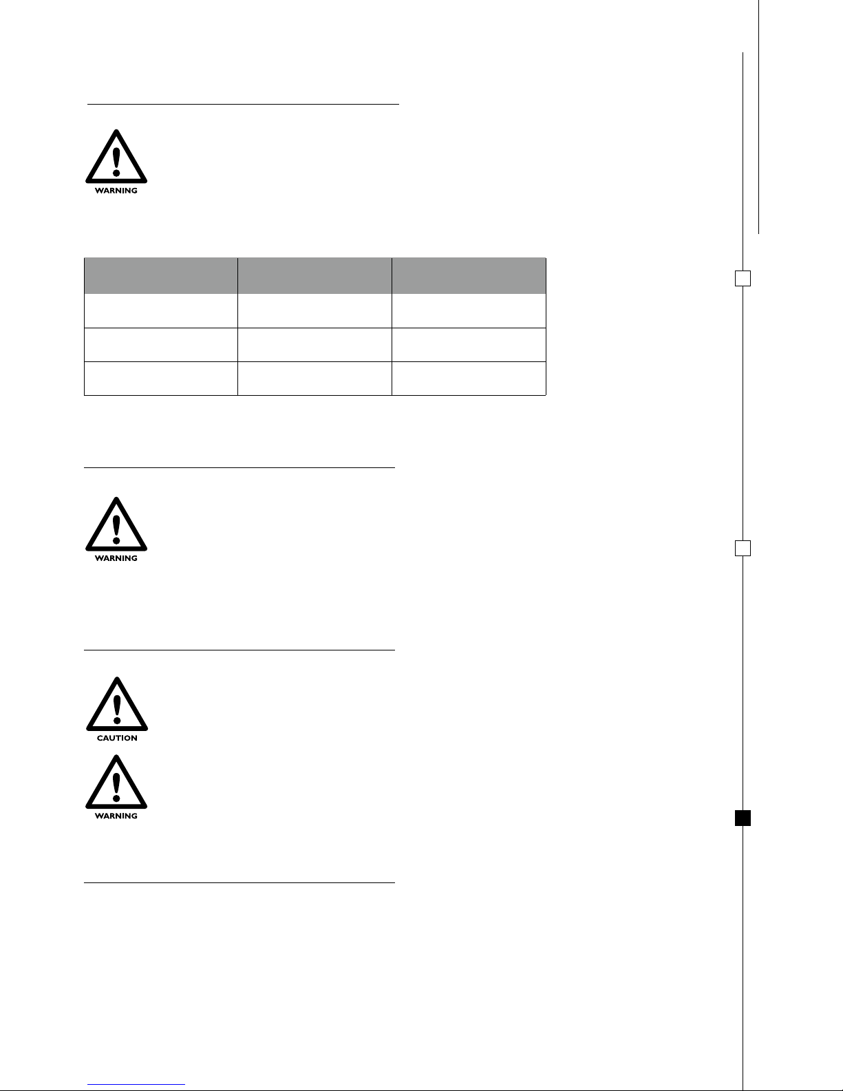
SAFETY ALERT SYMBOLS
COOKTOPS & COMBINATION UNITS
Instruction Book
FOR YOUR SAFETY
Safety Symbols alerting you to potential personal safety hazards. Obey all safety messages following these symbols.
MO0911 - MO8302 - MO8322 - MO8801D - MO8801S - MO8821D - MO8821S - MO9523RSUS - PI8002 - PI8022
PI8022A - PI8003 PI8023 - PI8621A - PI8621R - PI8621S - PI8802D - PI8802S - PI8822D - PI8822S - PI8842D - PI8842S
PI8862D - PI8862S
WARNING: if the information in this manual is not followed
exactly, a fire or explosion may result causing property
damage, personal ijury or death.
- Do not store or use gasoline or other flammable vapors
and liquids in the vicinity of this or any other appliance.
- WHAT TO DO IF YOU SMELL GAS
• Do not try light any appliance.
• Do not touch any electrical switch.
• Do not use any phone in your recreational vehicle.
• Clear the recreational vehicle of all occupants.
• Turn off the gas supply tank valve(s) or main gas supply.
• Immediately call your gas supplier for instructions.
• If you cannot reach your gas supplier, call the fire
department.
- Have the gas system checked and leakage source
corrected by a qualified installer, service agency,
manufacturer or dealer or the gas supplier.
WARNING
Avoid possible injury
or death.
CAUTION
Avoid possible injury and/or
property damage.
FOR YOUR SAFETY READ ALL INSTRUCTIONS BEFORE OPERATING APPLIANCE
INSTALLER: PROVIDE THESE INSTRUCTIONS TO THE CONSUMER.
CONSUMER: KEEP DOCUMENTS FOR FUTURE REFERENCE.
Page 2
EN GL IS H
2
CONTENTS
INSTALLATION 3
WARNING 3
HOLE 3
CONNECTING TO GAS SUPPLY 4
CONNECTING TO ELECTRICITY SUPPLY 4
FIXING 5
USE 6
SAFETY WARNINGS 6
CONTROLS 6
BURNERS 7
SELECTING BURNER 8
ELECTRONIC IGNITION COOKTOP 8
MANUAL IGNITION COOKTOP 8
COOKTOP FLAME REGULATION 8
VISUAL FLAME CONTROL 8
MAINTENANCE 9
INJECTOR 9
TEST PRESSURE POINT 9
CLEANING 9
WARRANTY 9
TECHNICAL PLAN 21-31
CARBON MONOXIDE POISONING
• NEVER USE THIS APPLIANCE AS A SPACE HEATER TO HEAT OR WARM THE ROOM.
DOING SO MAY RESULT IN CARBON MONOXIDE POISONING AND OVERHEATING
OF THE APPLIANCE.
• CARBON MONOXIDE (CO) POISONING PRODUCES FLU-LIKE SYMPTOMS, WATERY
EYES, HEADACHES, DIZZINESS, FATIGUE AND POSSIBLY DEATH. YOU CAN’T SEE
IT AND YOU CAN’T SMELL IT. IT’S AN INVISIBLE KILLER. IF THESE SYMPTOMS ARE
PRESENT DURING OPERATION OF THIS PRODUCT GET FRESH AIR IMMEDIATELY!
FOR YOUR SAFETY
Page 3
US E
MA IN TEN AN CE
IN STA LLAT IO N
EN GL IS H
3
WARNING
THIS APPLIANCE MUST BE INSTALLED IN ACCORDANCE WITH REGULATIONS IN
FORCE AND ONLY USED IN A WELL VENTILATED SPACE. READ THE INSTRUCTIONS
BEFORE INSTALLING OR USING THIS APPLIANCE.THE APPLIANCE MUST BE
INSTALLED BY SPECIALIST TECHNICIANS.
Installation must conform with local codes or in the absence of local codes, with the American National Standard
for Recreational Vehicles, ANSI/A119.2 and the National Electrical Code, ANSI/NFPA 70. In Canada, installation
must conform with CSA Z240.4.2-M.
This appliance is designed to cook foods only. Any other use is considered incorrect and dangerous.
Any storage cabinet placed directly above the appliance should not be used when one or more of the appliance
burners are on. The manufacturer is not responsible for any damage to persons or parts due to incorrect
installation, improper, incorrect, or irresponsible use.
For proper operation of your cooking appliance:
THE CABINET MUST BE
• properly constructed.
• squared to the countertop and cabinet face
THE OPENING IN CABINET MUST BE
• level from side to side and front to rear
The cabinet opening must be constructed so that no combustible material can be placed next to the cooktop sides.
The maximum depth of cabinets installed above the cooking top must be 13’’.
INFLAMMABLE MATERIALS MUST BE KEPT AT A SAFE DISTANCE FROM THE
APPLIANCE.
HOLE
Clearances are measured to combustible materials.
Make a hole in the furniture as indicated in FIG. 2 - PAG. 22
The cabinet must be suitably constructed and horizontally and vertically aligned.
The cabinet aperture must be perfectly squared and aligned.
If there are apertures for cabinet ventilation, avoid that any flammable material can enter these.
MINIMUM CLEARANCES FROM THE EXTERNAL COMBUSTIBLE SURFACES (FIG. 4 - PAG. 31):
SIDE CLEARANCE FROM THE EDGE OF THE
APPLIANCE TO ANY VERTICAL WALL
OVERHEAD CLEARANCE FROM THE
APPLIANCE COOKTOP TO A
RANGE-HOOD OR SHELVES
FROM THE LOWER PART OF THE APPLIANCE
TO THE WALL UNDERNEATH
0 mm - 0”
762 mm - 30”
THE CLEARANCE MAY BE 495 mm - 19 1/2”
ONLY WHEN A VENT HOOD IS INSTALLED IN
ACCORDANCE WITH ANSI/NFPA 1192 ET CSA Z240
25 mm - 1”
THE APPLIANCE IS NOT TO BE USED AS A SPACE HEATER.
Page 4
US E
IN STA LLAT IO N
MA IN TEN AN CE
EN GL IS H
4
DURING INSTALLATION AND CONNECTION, THE APPLIANCE GAS PIPE MUST
NOT BE TWISTED, STRETCHED OR DEFORMED IN ANY OTHER WAY CAUSING A
HAZARD TO THE USER.
THE APPLIANCE AND ITS INDIVIDUAL SHUTOFF VALVE MUST BE DISCONNECTED
FROM THE GAS SUPPLY PIPING SYSTEM DURING ANY PRESSURE TESTING.
LEAK TEST IN EXCESS OF 1/2 PSI (3,5 kPa) OF AIR PRESSURE WILL INVALIDATE
WARRANTY.
Do not over tighten connections to the gas regulator, as this may crack the regulator and cause a gas leak. Do not
allow the regulator to turn on the pipe when tightening fittings.
The connection of the gas supply pipe to the appliance must be gastight. Make sure that the gas supply pipe does
not touch any metal parts which get hot during operation of the appliance. It must also be installed so that there is
no contact with moving parts (e.g. drawers etc.) and must not pass through spaces where it can be deformed.
PRESSURE
GAS
INPUT
INLET MAX INLET MIN. MANIFOLD
propane
14 IN. W.C.
(1/2 PSI)
11 IN. W.C.
(1/2 PSI)
10 IN. W.C.
(1/2 PSI)
TOTAL FLOW RATE DEPENDS ON THE MODEL AND NUMBER OF BURNERS. FOR FURTHER DETAILS ON
TOTAL FLOW RATE FOR THE MODEL PURCHASED, REFER TO THE “ BURNER” SECTION.
CONNECTING TO ELECTRICITY SUPPLY
CONNECT THE UNIT TO 12 V DIRECT CURRENT ONLY
DO NOT CONNECT TO HIGHER VOLTAGE
CONNECT ONLY TO PROTECTED CIRCUIT FUSED FOR NOT MORE THAN 3 Amps.
This chapter provides details on wiring for the following models: MO8322 - MO9523RSUS - PI8022A - PI8023.
The above models must be wired as illustrated in the “WIRING DIAGRAM”. Voltage supply must be between 9
and 13 V
This appliance operate with the following gas and corresponding supply pressure. The gas category of the appliance is
given on the specifications label affixed to the appliance.
CONNECTING TO GAS SUPPLY
THE USE OF A TYPE OF GAS AND/OR OF A PRESSURE DIFFERENT FROM THOSE
PRESCRIBED BY DOMETIC, MAY CAUSE IRREGULAR OPERATING CONDITIONS
OF THE APPLIANCE; FOR THIS REASON, DOMETIC DECLINES ANY
RESPONSIBILITY ORIGINATING FROM INCORRECT USE OF THE APPLIANCE
ITSELF.
Check all connections for gas leaks using a non-corrosive leak detection fluid. Do not use a soap and water
solution. Never use a naked flame.
LEAK TESTING OF THE APPLIANCE SHALL BE CONDUCTED ACCORDING TO THE
MANUFACTURER’S INSTRUCTIONS.
Page 5
US E IN STA LLAT IO N
MA IN TEN AN CE
EN GL IS H
5
FIXING
The appliance must be secured by means of the fastening screws (FIG. 3 - PAG. 29):
1) insert the appliance in the unit;
2) tighten the screws.
ALWAYS DISCONNECT THE ELECTRIC SUPPLY BEFORE ANY TYPE OF
INTERVENTION ON THE UNIT
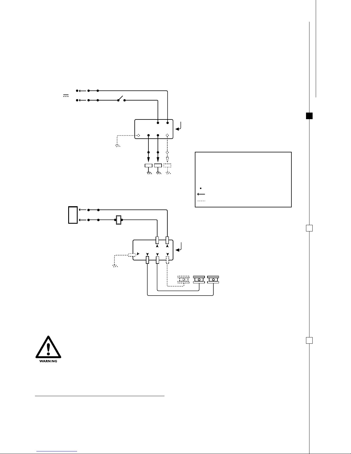
LABEL ALL WIRES PRIOR TO DISCONNECTION WHEN SERVICING CONTROLS.
WIRING ERRORS CAN CAUSE IMPROPER AND DANGEROUS OPERATION.
VERIFY PROPER OPERATION AFTER SERVICING.
If polarity is incorrect electronic igniter will not function.
R = RED Wire
G = GREEN WITH YELLOW STRIPES Wire
(only for three burner models)
W = WHITE Wire
BK = BLACK Wire
= WIRE Connection
= Wired by Installer
=
only for three burner models
SCHEMATIC DIAGRAM
CONNECTION DIAGRAM
W W W
TOP BURNERS
+
+
-
-
BKW BK
SWITCH
RBK
12 VOLT
BATTERY
IGNITION
MODULE
G
CONNECTORS
W W W
TOP BURNERS
+
+
-
-
BKW BK
SWITCH
RBK
IGNITION
MODULE
G
SPARK ELECTRODES
12 V
WIRING DIAGRAM:
Page 6
US E
IN STA LLAT IO N
MA IN TEN AN CE
EN GL IS H
6
SAFETY WARNINGS
THIS APPLIANCE MUST ONLY BE USED BY RESPONSIBLE ADULTS. DURING AND
IMMEDIATELY AFTER USE ACCESSIBLE PARTS MAY BE HOT; DO NOT TOUCH THEM
AND KEEP CHILDREN AWAY. ONCE COOKING IS COMPLETED, ENSURE THAT ALL
GAS CONTROL KNOBS ARE TURNED TO THE OFF POSITION. AFTER USE TURN OFF
THE GAS AT THE MAIN SUPPLY.
USE THE APPLIANCE ONLY IN A WELL VENTILATED SPACE. THE USE OF A GAS
COOKING APPLIANCE RESULTS IN THE PRODUCTION OF HEAT AND MOISTURE
IN THE ROOM IN WHICH IT IS INSTALLED. ENSURE THAT THE KITCHEN IS WELL
VENTILATED: KEEP NATURAL VENTILATION APERTURE OPEN OR INSTALL
A MECHANICAL VENTILATION DEVICE (MECHANICAL EXTRACTOR HOOD).
PROLONGED INTENSIVE USE OF THE APPLIANCE MAY REQUIRE ADDITIONAL
VENTILATION, FOR EXAMPLE OPENING OF A WINDOW, OR MORE EFFECTIVE
VENTILATION, FOR EXAMPLE INCREASING THE LEVEL OF THE MECHANICAL
VENTILATION WHERE PRESENT. COOKING FACILITIES MUST NOT BE USED
TO HEAT THE INSIDE OF THE VEHICLE. USE OVEN GLOVES OR POT HOLDERS
WHEN HANDLING HOT ELEMENTS. NEVER LAY PYREX LIDS OR OTHER ITEMS ON
THE BURNERS. KEEP APPLIANCE AREA CLEAR AND FREE FROM COMBUSTIBLE
MATERIALS, GASOLINE AND OTHER FLAMMABLE VAPORS AND LIQUIDS. DO NOT
OBSTRUCT THE FLOW OF COMBUSTION OR VENTILATION AIR.
CONTROLS
GLASS COOKTOP COVERS MAY SHATTER WHEN HEATED.
TOP COVER MUST BE OPEN WHEN ANY BURNER (COOKTOP, OVEN AND BROILER)
IS IN OPERATION AND TURN OFF ALL BURNERS (COOKTOP, OVEN AND BROILER)
BEFORE LOWERING THE COOKTOP GLASS COVER.
The following symbols indicate the burner corresponding to the control knob.
NOTE: different models may have different knobs and different symbols.
THIS SYMBOL IS PLACED NEXT TO THE COOKTOP BURNER KNOBS.
FULL DOT REFERS TO THE CORRESPONDING COOKTOP BURNER.
OFF
OFF
LIGHT
GAS OFF
HIGH FLAME
MINIMUM FLAME
IGNITE POSITION
The following symbols indicate the burner regulation corresponding to the knob position.
NOTE: different models may have different knobs and different symbols.
Page 7
US E IN STA LLAT IO N
MA IN TEN AN CE
EN GL IS H
7
OTHER SYMBOLS
PUSH BUTTON ELECTRONIC IGNITION
BURNERS
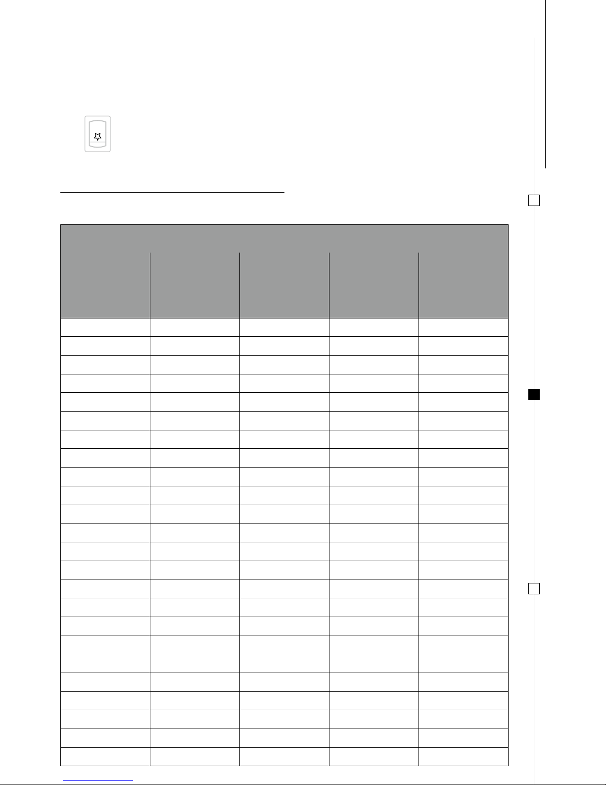
Technical specifications for burners referring to appliance model:
MODEL BURNERS TOTAL FLOW RATE
AUXILIARY SEMIRAPID RAPID
Ø 47 mm
Ø 1 27/32”
Ø 62 mm
Ø 2 7/16”
Ø 77 mm
Ø 3”
nr. (BTU/HR) nr. (BTU/HR) nr. (BTU/HR) BTU/HR
MO0911
1 (3700) 1 (5900) 9600
MO8302
1 (3700) 1 (5900) 9600
MO8322
1 (3700) 1 (5900) 9600
MO8801D
1 (3700) 3700
MO8801S
1 (3700) 3700
MO8821D
1 (3700) 3700
MO8821S
1 (3700) 3700
MO9523RSUS
1 (3700) 1 (5900) 1 (7200) 16800
PI8002
1 (3700) 1 (5900) 9600
PI8022
1 (3700) 1 (5900) 9600
PI8022A
1 (3700) 1 (5900) 9600
PI8003
1 (3700) 2 (5900) 15500
PI8023
1 (3700) 2 (5900) 15500
PI8621A
1 (3700) 3700
PI8621R
1 (7200) 7200
PI8621S
1 (5900) 5900
PI8802D
1 (3700) 1 (7200) 10900
PI8802S
1 (3700) 1 (7200) 10900
PI8822D
1 (3700) 1 (7200) 10900
PI8822S
1 (3700) 1 (7200) 10900
PI8842D
1 (3700) 1 (7200) 10900
PI8842S
1 (3700) 1 (7200) 10900
PI8862D
1 (3700) 1 (7200) 10900
PI8862S
1 (3700) 1 (7200) 10900
Page 8
US E
IN STA LLAT IO N
MA IN TEN AN CE
EN GL IS H
8
VISUAL FLAME CONTROL
Propane: The flames internal tongue should be blue and the outline well defined.
6 - 16 cm
2 3/8” - 6 5/16”
16 - 22 cm
6 5/16” - 8 21/32”
AUXILIARY
Ø 47 mm - 1 27/32”
SEMIRAPID
Ø 62 mm - 2 7/16”
BURNER PAN DIAMETER
16 - 22 cm
6 5/16” - 8 21/32”
RAPID
Ø 77 mm - 3”
To ignite burner, gently push-in and turn the control knob to IGNITE POSITION and maintaining the knob pushed at
the same time press the electronic ignition pushbutton. Once the burner is alight maintain the knob in this position
for few seconds to the ensure the flame remains alight.
MANUAL IGNITION COOKTOP
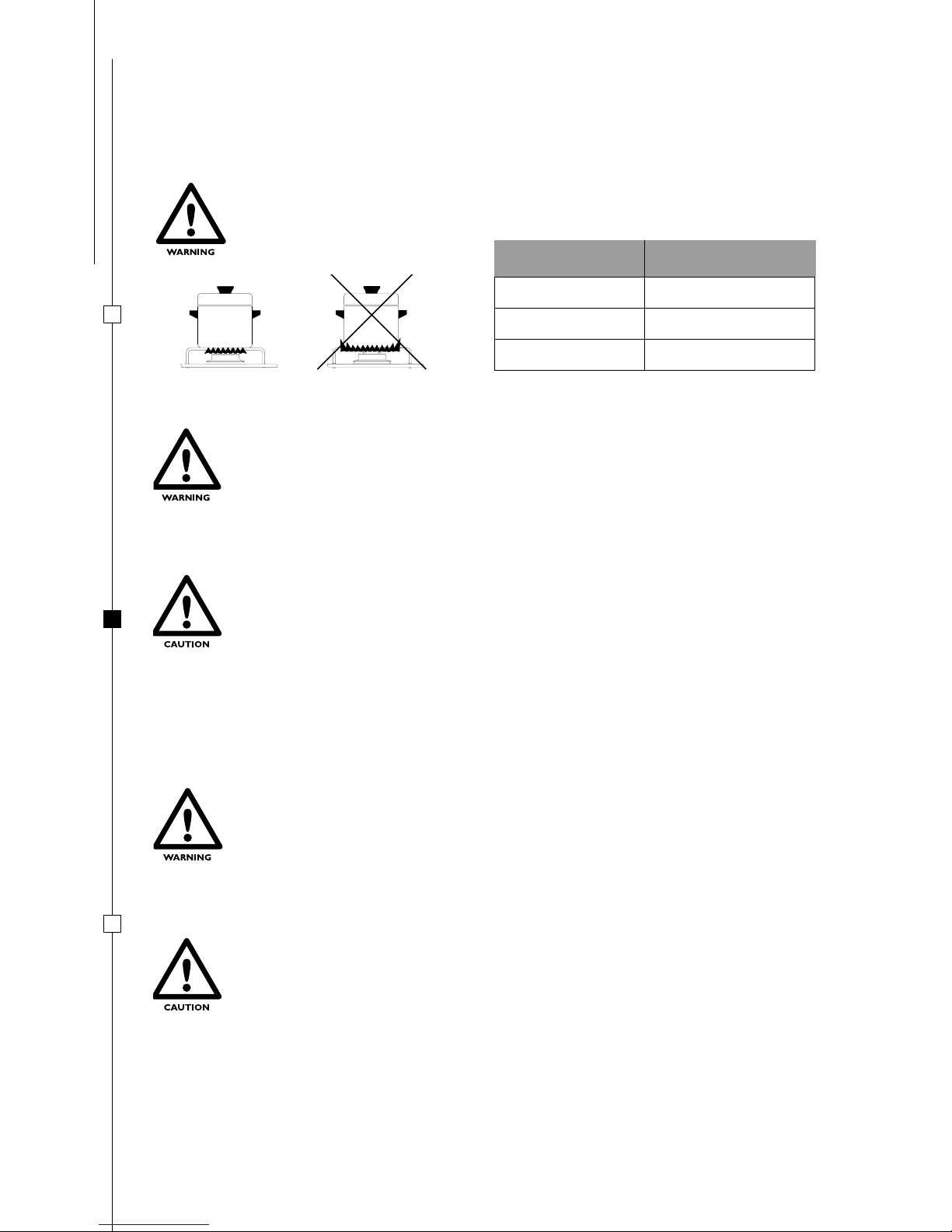
THE FLAME MUST NEVER EXTEND BEYOND THE EDGE OF THE PAN. CENTER THE
PAN OVER THE BURNER ENSURING STABILITY ON THE PAN SUPPORT.
SELECTING BURNER
ELECTRONIC IGNITION COOKTOP (DEPENDING ON MODEL)
Manual ignition when the appliance is not fitted with the electronic ignition feature or in the event of failure in the
electronic ignition.
MAKE SURE THERE ARE NO PANS OR OTHER ANY OBJECTS ON THE BURNERS
WHEN IGNITING.
IF THE BURNER DOES NOT IGNITE IMMEDIATELY REPEAT IGNITION AFTER
HAVING FOLLOWED EACH STEP BELOW:
• TURN THE KNOB TO “MINIMUM FLAME”
• PROCEED WITH MANUAL IGNITION
• CHECK THERE IS SUFFICIENT GAS IN THE GAS BOTTLE.
IF THE APPLIANCE STILL DOES NOT IGNITE SHUT OFF THE GAS SUPPLY AT THE
MAIN GAS TAP AND CONTACT YOUR LOCAL DEALER.
MAKE SURE THERE ARE NO PANS OR OTHER ANY OBJECTS ON THE BURNERS
WHEN IGNITING.
To ignite burner, gently push-in and turn the control knob to IGNITE POSITION and maintaining the knob pushed at
the same time light the burner with a match or gas lighter. Once the burner is alight maintain the knob in this position
for few seconds to the ensure the flame remains alight.
IF THE BURNER DOES NOT IGNITE IMMEDIATELY CHECK THERE IS SUFFICIENT
GAS IN THE GAS BOTTLE.
IF THE APPLIANCE STILL DOES NOT IGNITE SHUT OFF THE GAS SUPPLY AT THE
MAIN GAS TAP AND CONTACT YOUR LOCAL DEALER.
COOKTOP FLAME REGULATION
To regulate flame turn the knob to the desired cooking flame.
Page 9
US E IN STA LLAT IO N
MA IN TEN AN CE
INJECTOR
CLEANING AND/OR REPLACEMENT OF BURNER INJECTORS (FIG. 1 - PAG. 21)
When removing or installing an injector, the holder must be held with a suitable tool.
THE OPERATIONS MUST BE CARRIED OUT BY AUTHORIZED PERSONNEL.
DOMETIC DECLINES ANY RESPONSIBILITY RELATED TO SAID INTERVENTION.
BURNERS HOBBED
NUMBER
AUXILIARY
Ø 47 mm - 1 27/32”
SEMIRAPID
Ø 62 mm - 2 7/16”
RAPID
Ø 77 mm - 3”
57
72
80
0,57
0,72
0,80
EN GL IS H
9
TURN OFF THE APPLIANCE AND ALLOW TO COOL BEFORE CLEANING.
COLD WATER OR A DAMP CLOTH MAY DAMAGE HOT SURFACES.
CLEANING
TEST PRESSURE POINT
THE OPERATIONS MUST BE CARRIED OUT BY AUTHORIZED PERSONNEL.
DOMETIC DECLINES ANY RESPONSIBILITY RELATED TO SAID INTERVENTION.
The test pressure point is located on the pressure regulator.
WARRANTY
In case of warranty claim or any repair or replacement which becomes necessary, the vehicle or part dealer who sold
the product should be contacted. Give model and serial number on all repair part orders and correspondence.
DO NOT USE ABRASIVE, CORROSIVE, CHLORIDE-BASED PRODUCTS OR STEEL OR
OTHER SCOURING PADS. DO NOT LEAVE ACIDIC SUBSTANCES E.G. VINEGAR, SALT,
LEMON JUICE ETC. ON THE APPLIANCE SURFACES. STAINLESS STEEL SURFACES
AND ENAMELED PARTS SHOULD ONLY BE WASHED WITH SOAPY WATER OR
NEUTRAL DETERGENT, RINSED AND DRIED. ONLY USE CLEAN SPONGES OR
CLOTHS.
Page 10

NOTE
10
Page 11

w w w . d o m e t i c . c o m
ATTENTION ET SYMBOLES DE SECURITE
PLAN DE CUISSON ET PLAN
DE CUISSON INTEGRE AVEC EVIER
Livret d’instructions
POUR VOTRE SECURITE
Les symboles de sécurité vous avertissent des risques potentiels pour votre sécurité personnelle. Respecter tous
les messages de sécurité en suivant ces symboles.
MO0911 - MO8302 - MO8322 - MO8801D - MO8801S - MO8821D - MO8821S - MO9523RSUS - PI8002 - PI8022
PI8022A - PI8003 PI8023 - PI8621A - PI8621R - PI8621S - PI8802D - PI8802S - PI8822D - PI8822S - PI8842D - PI8842S
PI8862D - PI8862S
ATTENTION: suivre scrupuleusement les instructions contenues dans ce
livret d’instructions, car dans le cas contraire on pourrait provoquer un
incendie ou une explosion en causant des dommages à l’appareil, en risquant
de blesser des personnes ou de provoquer la mort.
- Ne pas stocker ou utiliser de l’essence ou d’autres produits
ou liquides inflammables à proximité de cet appareil.
- QUE FAIRE SI ON SENT UNE ODEUR DE GAZ
• N’allumer aucun appareil.
• Ne pas toucher les interrupteurs électriques.
• Ne pas utiliser de téléphone à l’intérieur de votre véhicule.
• Faire évacuer tous les occupants du véhicule.
• Fermer le robinet du gaz sur la soupape ou sur
l’alimentation générale.
• Appeler immédiatement la société distributrice de gaz
pour recevoir des instructions.
• Si vous n’arrivez pas à la joindre, appelez les pompiers.
- Faire contrôler l’installation du gaz et réparer les éventuelles
fuites par un technicien qualifié, un centre d’assistance
autorisé, le constructeur, le revendeur ou la société de
distribution du gaz.
ATTENTION
Danger de lésion
ou de mort.
IMPORTANT
Pour éviter les lésions possibles et/ou les possibilités
de panne.
POUR VOTRE SECURITE, LISEZ TOUTES LES INSTRUCTIONS AVANT DE FAIRE
FONCTIONNER L’APPAREIL
INSTALLATEUR: FOURNIR CES INSTRUCTIONS A L’USAGER.
UTILISATEUR: CONSERVER CE DOCUMENT COMME REFERENCE FUTURE.
Page 12

FR AN C AI S
12
TABLE DES MATIERES
INSTALLATION 13
AVERTISSEMENTS 13
PERÇAGE 13
RACCORDEMENT AU GAZ 14
BRANCHEMENT A L’ALIMENTATION ELECTRIQUE 14
FIXATION 15
USAGE 16
AVERTISSEMENTS DE SECURITE 16
TABLEAU DE COMMANDE 16
BRULEURS 17
CHOIX DU BRULEUR 18
ALLUMAGE ELECTRONIQUE DU PLAN DE CUISSON 18
ALLUMAGE MANUEL DU PLAN DE CUISSON 18
REGLAGE DU PLAN DE CUISSON 18
CONTROLE VISUEL DE LA FLAMME
18
ENTRETIEN 19
INJECTEURS 19
DISPOSITIF POUR TESTER LA PRESSION 19
NETTOYAGE 19
GARANTIE 19
DESSINS TECHNIQUES 21-31
INTOXICATION DUE AU MONOXYDE DE CARBONE
• NE JAMAIS UTILISER CET APPAREIL COMME UN CHAUFFAGE, PARCE QU’ON
POURRAIT SURCHAUFFER L’APPAREIL ET/OU CAUSER UNE INTOXICATION DUE
AU MONOXYDE DE CARBONE.
• L’INTOXICATION DUE AU MONOXYDE DE CARBONE (CO) PRODUIT DES
SYMPTOMES SEMBLABLES A CEUX CAUSES PAR LA GRIPPE, LARMOIEMENT DES
YEUX, MAL DE TETE, FAIBLESSE, FATIGUE ET POURRAIT CAUSER LA MORT. LE
MONOXYDE DE CARBONE EST INVISIBLE ET INODORE. C’ES T UN ASSASSIN
INVISIBLE. SI VOUS CONSTATEZ LA PRESENCE D’UN DE CES SYMPTOMES PENDANT
L’USAGE DE CET APPAREIL, SORTEZ IMMEDIATEMENT DU VEHICULE ET RESPIREZ
DE L’AIR FRAIS!
POUR VOTRE SECURITE
Page 13

US AGE
EN TR ETI EN
FR AN C AI S
13
AVERTISSEMENTS
CET APPAREIL DOIT ETRE INSTALLE CONFORMEMENT A LA LEGISLATION EN
VIGUEUR ET UTILISE UNIQUEMENT DANS UN LOCAL BIEN AERE. CONSULTER LES
INSTRUCTIONS AVANT D’INSTALLER ET D’UTILISER CET APPAREIL. L’APPAREIL
DOIT ETRE INSTALLE PAR DES TECHNICIENS SPECIALISES.
L’installation doit être conforme à la législation locale ou faute de législation locale, aux normes nationales
américaines qui règlementent les véhicules de détente, ANSI/A119.2 et aux normes nationales électriques, ANSI/
NFPA 70. Pour le Canada, l’installation doit être conforme à la norme CSA Z240.4.2-M.
Cet appareil a été conçu uniquement pour la cuisson d’aliments. Tout autre usage doit être considéré comme
incorrect et donc dangereux. Toute armoire de rangement qui se trouverait directement au-dessus de l’appareil
ne devra pas être utilisée pendant le fonctionnement d’un ou de plusieurs brûleurs. Le constructeur décline toute
responsabilité pour les dommages causés aux biens ou aux personnes dus à une mauvaise installation ou à un usage
impropre, incorrect ou irresponsable de l’appareil.
Pour un usage correct du plan de cuisson:
L’ARMOIRE DEVRA ETRE
• construite correctement.
• en équerre avec le plan de cuisson et la façade de l’armoire
L’OUVERTURE DE L’ARMOIRE DEVRA ETRE
• nivelée latéralement, de face et à l’arrière
L’ouverture de l’armoire devra être réalisée de sorte qu’aucun matériau combustible ne puisse être placé sur les côtés
du plan de cuisson. La profondeur de l’armoire installée au-dessus du plan de cuisson doit être de maximum 13’’.
LES MATERIAUX INFLAMMABLES DOIVENT ETRE CONSERVES LOIN DE
L’APPAREIL.
PERÇAGE
Les espaces libres sont mesurés en se référant à des matériaux combustibles.
Effectuer un trou dans l’armoire comme indiqué dans la FIG. 2 - PAG. 22
L’armoire doit être conçue de façon appropriée et alignée horizontalement et verticalement.
L’ouverture de l’armoire doit être parfaitement en équerre et alignée.
Si l’armoire est munies d’ouverture pour l’aération,
éviter que tout matériau inflammable puisse passer à l’intérieur.
CET APPAREIL NE DOIT PAS ETRE UTILISE COMME CHAUFFAGE.
ESPACE LIBRE MINIMUM ENTRE L’APPAREIL ET LES SURFACES INFLAMMABLES EXTERNES
(FIG. 4 - PAGE 31):
ESPACE LIBRE LATERALEMENT ENTRE
LE BORD DU L’APPAREIL ET N’IMPORTE
QUELLE PAROIS VERTICALE
ESPACE LIBRE VERS LE HAUT ENTRE LE
PLAN DE CUISSON ET UNE ETAGERE OU
UNE HOTTE
ENTRE LA PARTIE INFERIEURE DE
L’APPAREIL ET LA SURFACE
0 mm - 0”
762 mm - 30”
LA DISTANCE PEUT ÊTRE 495 mm - 19 1/2”
UNIQUEMENT DU CAS OÙ EST INSTALLÉ
UNE HOTTE EN ACCORD AVEC
ANSI/NFPA 1192 ET CSAZ240
25 mm - 1”
Page 14

US AGE
EN TR ETI EN
FR AN C AI S
14
PENDANT LES OPERATIONS D’INSTALLATION ET DE BRANCHEMENT, LE TUYAU
D’AMENEE DU GAZ DE L’APPAREIL NE DOIT PAS ETRE SUJET A DES TORSIONS,
DES TRACTIONS OU D’AUTRES CONTRAINTES, QUI POURRAIENT ETRE
DANGEREUSES POUR L’UTILISATEUR.
PENDANT LES TESTS DE PRESSION DU GAZ, IL FAUT DEBRANCHER L’APPAREIL ET
FERMER LA VANNE D’AMENEE DU GAZ. LES TESTS DE FUITE EXCEDANT 1/2 PSI (3,5
kPa) DE PRESSION DE L’AIR FERONT DECHOIR LA GARANTIE.
Ne pas serrer trop fort le régulateur du gaz, car il pourrait se fêler et causer des fuites de gaz. Ne pas faire tourner
le régulateur autour du tuyau pendant la fixation des raccordements. Le raccordement du tuyau d’alimentation gaz
à l’appareil doit être serré de façon appropriée pour le gaz. Vérifier que le tuyau d’amenée du gaz ne touche pas
d’éléments en métal qui se réchauffent pendant le fonctionnement de l’appareil. Il faudra également l’installer de
sorte qu’il n’entre pas en contact avec des parties en mouvement (ex. tiroirs, etc.) et il ne devra pas traverser des
espaces à travers lesquels il pourrait se déformer.
PRESSION
ENTREE DE
GAZ
ENTREE MAX ENTREE MIN. RACCORD
propane
14 IN. W.C.
(1/2 PSI)
11 IN. W.C.
(1/2 PSI)
10 IN. W.C.
(1/2 PSI)
LE DEBIT TOTAL DEPEND DU MODELE ET DU NOMBRE DE BRULEURS. POUR PLUS DE DETAILS SUR LE DEBIT
TOTAL DU MODELE QUE VOUS POSSEDEZ, CONSULTER LA SECTION “ BRULEURS”.
BRANCHEMENT A
L’ALIMENTATION ELECTRIQUE
CET APPAREIL PEUT ETRE UNIQUEMENT BRANCHE A UNE UNITE DE 12 V
NE PAS BRANCHER L’APPAREIL A DES TENSIONS SUPERIEURES
LE CIRCUIT DOIT ETRE PROTEGE PAR UN FUSIBLE NON SUPERIEUR A 3 Ampères.
Ce chapitre fournit les détails sur le câblage pour les modèles suivants: MO8322 - MO9523RSUS
PI8022A - PI8023.
Le modèle ci-dessus doit être branché comme indiqué dans le “SCHEMA ELECTRIQUE”.
La tension d’alimentation doit être comprise entre 9 et 13 V
Cet appareil peut fonctionner avec les gaz suivants et les pressions d’alimentation correspondantes.
La catégorie selon lesquelles l’appareil a été réglé, est indiquée clairement sur l’étiquette d’identification collée sur
l’appareil.
RACCORDEMENT AU GAZ
L’USAGE D’UN TYPE DE GAZ ET/OU D’UNE PRESSION DIFFERENTE DE
CELLE PRESCRITE PAR LA MAISON DOMETIC, POURRAIT PROVOQUER LE
FONCTIONNEMENT IRREGULIER DE L’APPAREIL; POUR CETTE RAISON,
DOMETIC DECLINE TOUTE RESPONSABILITE DUE A L’USAGE INCORRECT DE
L’APPAREIL MEME.
Vérifier tous les raccordements du gaz en utilisant un liquide non-corrosif pour la détection des fuites. Ne pas
utiliser une solution d’eau savonneuse. Ne jamais utiliser de flammes libres.
LE CONTROLE DES FUITES SUR L’APPAREIL DEVRA ETRE EFFECTUE
CONFORMEMENT AUX INSTRUCTIONS DU CONSTRUCTEUR.
Page 15

US AGE
EN TR ETI EN
FR AN C AI S
15
FIXATION
Cet appareil doit être fixé à l’aide de vis de fixation (FIG. 3 - PAGE 29):
1) insérer l’appareil dans l’unité;
2) serrer les vis.
DEBRANCHER TOUJOURS L ’APPAREIL DE L ’ALIMENTATION ELECTRIQUE AVANT
D’EFFECTUERTOUTE INTERVENTION
MARQUERTOUS LES FILS AVANT DE LES DEBR ANCHER POUR EFFECTUER DES
CONTROLES D’ENTRETIEN. TOUTE ERREUR DE CABLAGE POURRAIT CAUSER
UN FONCTIONNEMENT ANORMAL E T DANGEREUX DE L’APPAREIL. VERIFIER
QUE L’APPAREIL FONCTIONNE CORRECTEMENT APRES LES OPERATIONS
D’ENTRETIEN.
Si les polarités ne sont pas correcte, l’allumage électronique ne fonctionnera pas.
R = Fil ROUGE
G = Fil à LIGNES VERTES ET JAUNES
(uniquement pour les modèles
à trois brûleurs)
W = Fil BLANC
BK = Fil NOIR
= Fil de BRANCHEMENT
= Câblage de l'installateur
= uniquement pour les modèles
à trois brûleurs
SCHEMA
SCHEMA DE BRANCHEMENT
W W W
BRULEURS
+
+
-
-
BKW BK
INTERRUPTEUR
RBK
12 VOLT
BATTERIE
MODULE
ALLUMAGE
G
CONNECTEURS
W W W
BRULEURS
+
+
-
-
BKW BK
INTERRUPTEUR
RBK
MODULE
ALLUMAGE
G
ELECTRODES ALLUMAGE
12 V
SCHEMA ELECTRIQUE:
Page 16

US AGE
EN TR ETI EN
FR AN C AI S
16
AVERTISSEMENTS DE SECURITE
CET APPAREIL DOIT ETRE UTILISE UNIQUEMENT PAR DES ADULTES
RESPONSABLES. PENDANT L’UTILISATION ET IMMEDIATEMENT APRES LES
PARTIES ACCESSIBLES PEUVENT ETRE CHAUDES; NE PAS LES TOUCHER ET
TENIR LES ENFANTS A DISTANCE. A LA FIN DE LA CUISSON, NE PAS OUBLIER DE
REPLACER LES BOUTONS SUR LA POSITION ETEINT. APRES L’USAGE, FERMER LE
ROBINET PRINCIPAL DU TUYAU DE GAZ.
L’UTILISATION D’UN APPAREIL AU GAZ PRODUIT DE LA CHALEUR, DE L’HUMIDITE
DANS LE LOCAL OU IL EST INSTALLE. IL FAUDRA DONC GARANTIR UNE
BONNE AERATION DE LA CUISINE: MAINTENIR LES OUVERTURES D’AERATION
NATURELLE OUVERTES OU INSTALLER UN DISPOSITIF D’AERATION MECANIQUE
(HOTTE D’ASPIRATION MECANIQUE). UNE UTILISATION INTENSE ET PROLONGEE
DE L’APPAREIL PEUT RENDRE NECESSAIRE UNE AERATION SUPPLEMENTAIRE,
PAR EXEMPLE L’OUVERTURE D’UNE FENETRE OU UNE AERATION PLUS EFFICACE,
PAR EXEMPLE EN AUGMENTANT LA PUISSANCE DE L’EVENTUELLE ASPIRATION
MECANIQUE. LES APPAREILS DE CUISSON NE DOIVENT JAMAIS ETRE UTILISES
POUR RECHAUFFER LE LOCAL. UTILISER DES GANTS DE PROTECTION POUR
MANIPULER LES ELEMENTS CHAUDS. NE JAMAIS DEPOSER DE COUVERCLES
EN PYREX OU D’AUTRES ELEMENTS SUR LES BRULEURS. NE PAS TENIR DES
MATERIAUX OU DES LIQUIDES INFLAMMABLES, OU DE L’ESSENCE AUX
ALENTOURS DE L’APPAREIL. NE PAS OBSTRUER LE FLUX DE COMBUSTION OU
L’AERATION.
TABLEAU DE COMMANDE
LES COUVERCLES EN VERRE POURRAIENT SE BRISER A CAUSE DE LA CHALEUR.
LE COUVERCLE DOIT TOUJOURS ETRE OUVERT PENDANT LE FONCTIONNEMENT
D’UN BRULEUR (PLAN DE CUISSON, FOUR ET GRIL) ET ETEINDRE TOUS LES
BRULEURS (PLAN DE CUISSON, FOUR ET GRIL) AVANT DE FERMER LE COUVERCLE.
Les symboles suivants indiquent le brûleur correspondant au bouton de commande.
REMARQUE: selon le modèle les boutons et les symboles peuvent être différents.
OFF
OFF
LIGHT
CE SYMBOLE SE TROUVE PRES DES BOUTONS ET REGLE UN DES BRULEURS
DU PLAN DE CUISSON. LE POINT NOIR INDIQUE A QUEL BRULEUR DU PLAN DE
CUISSON CORRESPOND LE BOUTON.
GAZ FERME
GRANDE FLAMME
PETITE FLAMME
POSITION D’ALLUMAGE
Les symboles suivants indiquent le réglage du brûleur en fonction de la position du bouton de réglage.
REMARQUE: selon le modèle les boutons et les symboles peuvent être différents.
Page 17

US AGE
EN TR ETI EN
FR AN C AI S
17
AUTRES SYMBOLES
BOUTON D’ALLUMAGE ELECTRONIQUE
BRULEURS
Ci-dessous on donne les caractéristiques des brûleurs en fonction des différents modèles:
MODELE BRULEURS DEBIT TOTAL
AUXILIAIRE SEMIRAPIDE RAPIDE
Ø 47 mm
Ø 1 27/32”
Ø 62 mm
Ø 2 7/16”
Ø 77 mm
Ø 3”
nr. (BTU/HR) nr. (BTU/HR) nr. (BTU/HR) BTU/HR
MO0911
1 (3700) 1 (5900) 9600
MO8302
1 (3700) 1 (5900) 9600
MO8322
1 (3700) 1 (5900) 9600
MO8801D
1 (3700) 3700
MO8801S
1 (3700) 3700
MO8821D
1 (3700) 3700
MO8821S
1 (3700) 3700
MO9523RSUS
1 (3700) 1 (5900) 1 (7200) 16800
PI8002
1 (3700) 1 (5900) 9600
PI8022
1 (3700) 1 (5900) 9600
PI8022A
1 (3700) 1 (5900) 9600
PI8003
1 (3700) 2 (5900) 15500
PI8023
1 (3700) 2 (5900) 15500
PI8621A
1 (3700) 3700
PI8621R
1 (7200) 7200
PI8621S
1 (5900) 5900
PI8802D
1 (3700) 1 (7200) 10900
PI8802S
1 (3700) 1 (7200) 10900
PI8822D
1 (3700) 1 (7200) 10900
PI8822S
1 (3700) 1 (7200) 10900
PI8842D
1 (3700) 1 (7200) 10900
PI8842S
1 (3700) 1 (7200) 10900
PI8862D
1 (3700) 1 (7200) 10900
PI8862S
1 (3700) 1 (7200) 10900
Page 18

US AGE
EN TR ETI EN
CONTROLE VISUEL DE LA FLAMME
Propane: Le dard intérieur de la flamme doit être bleu et le contour net.
6 - 16 cm
2 3/8” - 6 5/16”
16 - 22 cm
6 5/16” - 8 21/32”
AUXILIAIRE
Ø 47 mm - 1 27/32”
SEMIRAPIDE
Ø 62 mm - 2 7/16”
BRULEUR DIAMETRE CASSEROLE
16 - 22 cm
6 5/16” - 8 21/32”
RAPIDE
Ø 77 mm - 3”
Pour produire la flamme, appuyer à fond sur le bouton de commande et le tourner sur la POSITION D’ALLUMAGE.
Simultanément appuyer sur le bouton d’allumage électronique. Quand la flamme s’allume, maintenir le bouton enfoncé
pendant quelques secondes pour que la flamme reste allumée.
ALLUMAGE MANUEL DU PLAN DE CUISSON
LA FLAMME NE DOIT PAS DEPASSER LE FOND DE LA CASSEROLE. PLACER LA
CASSEROLE AU CENTRE DU BRULEUR, DE SORTE QU’ELLE SOIT STABLE SUR LA
GRILLE DE SUPPORT.
CHOIX DU BRULEUR
L’allumage manuel s’utilise en cas d’absence d’allumage électronique ou en cas de panne de celui-ci.
L’ALLUMAGE DOIT ETRE EFFECTUEE SANS AUCUNE CASSEROLE OU AUTRE
OBJET SUR LES BRULEURS.
SI LE BRULEUR NE S’ALLUME PAS IMMEDIATEMENT, REPETER L’OPERATION APRES
AVOIR EFFECTUES LES CONTROLES SUIVANTS:
• TOURNER LE BOUTON SUR LA POSITION “PETITE FLAMME”
• PROCEDER A L’ALLUMAGE MANUEL
• CONTROLER QU’IL Y AIT DU GAZ DANS LA BOUTEILLE
SI L’APPAREIL NE FONCTIONNE TOUJOURS PAS, FERMER LE ROBINET D’AMENEE
DU GAZ ET CONTACTER VOTRE REVENDEUR.
L’ALLUMAGE DOIT ETRE EFFECTUE SANS AUCUNE CASSEROLE OU AUTRE OBJET
SUR LES BRULEURS.
Pour produire la flamme, appuyer à fond sur le bouton de commande et le tourner sur la POSITION D’ALLUMAGE.
Simultanément allumer le brûleur avec une allumette ou un allume-gaz. Quand la flamme s’allume, maintenir le bouton
enfoncé pendant quelques secondes pour que la flamme reste allumée.
SI LE BRULEUR NE S’ALLUME PAS IMMEDIATEMENT, CONTROLER QU’IL Y AIT DU
GAZ DANS LA BOUTEILLE.
SI L’APPAREIL NE FONCTIONNE TOUJOURS PAS, FERMER LE ROBINET D’AMENEE
DU GAZ ET CONTACTER VOTRE REVENDEUR.
REGLAGE DE LA FLAMME DU PLAN DE CUISSON
Pour régler la flamme, tourner le bouton sur la position désirée.
FR AN C AI S
18
Page 19

US AGE
EN TR ETI EN
INJECTEURS
NETTOYAGE ET/OU SUBSTITUTION DES INJECTEURS (FIG. 1 - PAGE 21)
Le démontage et le montage des injecteurs doit être effectué en maintenant bloqué à l’aide d’un outil approprié le
porte-injecteur.
LES INTERVENTIONS DOIVENT ETRE EFFECTUEES PAR
DU PERSONNEL AUTORISE. LA MAISON DOMETIC DECLINE TOUTE
RESPONSABILITE DERIVANT DE L’INTERVENTION MEME.
BRULEURS INJECTEUR
Ø mm
N° ESTAMPILLE
AUXILIAIRES
Ø 47 mm - 1 27/32”
SEMIRAPIDE
Ø 62 mm - 2 7/16”
RAPIDE
Ø 77 mm - 3”
57
72
80
0,57
0,72
0,80
ETEINDRE L’APPAREIL ET ATTENDRE QU’IL SE SOIT REFROIDI AVANT DE
COMMENCER LE NETTOYAGE. LES SURFACES CHAUDES EN CONTACT AVEC L’EAU
FROIDE OU UN CHIFFON HUMIDE PEUVENT S’ABIMER.
NETTOYAGE
DISPOSITIF POUR TESTER LA PRESSION
LES INTERVENTIONS DOIVENT ETRE EFFECTUEES PAR DU PERSONNEL
AUTORISE. LA MAISON DOMETIC DECLINE TOUTE RESPONSABILITE DERIVANT
DE L’INTERVENTION MEME.
Le dispositif pour tester la pression se trouve sur le régulateur de pression.
GARANTIE
Si on doit faire intervenir la garantie pour une réparation ou pour une substitution, contacter le revendeur du
véhicule ou le revendeur de l’appareil. Mentionner le modèle et le numéro de série de l’appareil sur toute demande de
réparation et dans la correspondance en général.
NE PAS UTILISER DE PRODUITS ABRASIFS, CORROSIFS, A BASE DE CHLORE, OU DE
LA PAILLETTE D’ACIER. NE PAS LAISSER DE SUBSTANCES ACIDES, PAR EXEMPLE
DU VINAIGRE, SEL, JUS DE CITRON ETC. SUR LES SURFACES DE L’APPAREIL. LES
SURFACES EN ACIER INOXYDABLE ET LES PARTIES EMAILLEES DOIVENT ETRE
NETTOYEES AVEC DE L’EAU ET DU SAVON OU DU DETERGENT NEUTRE, RINCEES
ET SECHEES. UTILISER UNIQUEMENT UNE EPONGE OU DES CHIFFONS PROPRES.
FR AN C AI S
19
Page 20

US AGE
EN TR ETI EN
NOTE
FR AN C AI S
20
Page 21

21
1 FIG.
Page 22

22
2 FIG.
mm inch
A
B
C
766
286
35
30 5/32”
11 1/4”
1 3/8”
A
B
C
MIN. 25 mm - 1”
C
C
C
C
B
MIN. 14 mm - 9/16”
A
mm inch
A
B
C
426
666
173
16 25/32”
26 7/32”
6 13/16”
MO0911
MO8302
MO8322
Page 23

23
mm inch
A
B
C
D
E
F
G
H
I
511
212,4
106
202
114
89
100
88
8,5
20 1/8”
8 3/8”
4 3/16”
7 15/16”
4 1/2”
3 1/2”
3 15/16”
3 15/32”
11/32”
mm inch
J
K
L
M
N
O
P
Q
R
408
213
125
133,2
693
195
182
241,3
158,3
16 1/6”
8 3/8”
4 29/32”
5 1/4”
27 9/32”
7 11/16”
7 5/32”
9 1/2”
6 7/32”
mm inch
S
T
U
V
W
X
Y
99
77
79,1
125,4
5,3
62
208
3 29/32”
3 3/64”
3 1/8”
4 15/16”
7/32”
2 7/16”
8 3/16”
A
J
H
O
P
S
T
Y
H
K
L
E
D
V
G
X
B
W
R
MIN. 16 mm - 5/8”
M
Q
U
F
C
A
A
I
A-A
N
MO8801D
MO8821D
PI8802D
PI8822D
PI8842D
PI8862D
Page 24

24
mm inch
A
B
C
D
E
F
G
H
I
8,5
511
212,4
89
114
202
106
100
88
11/32”
20 1/8”
8 3/8”
3 1/2”
4 1/2”
7 15/16”
4 3/16”
3 15/16”
3 15/32”
mm inch
J
K
L
M
N
O
P
Q
R
125,4
79,1
62
5,3
208
77
99
241,3
158,3
4 15/16”
3 1/8”
2 7/16”
7/32”
8 3/16”
3 3/64”
3 29/32”
9 1/2”
6 7/32”
mm inch
S
T
U
V
W
X
Y
182
195
408
213
133,2
125
693
7 5/32”
7 11/16”
16 1/6”
8 3/8”
5 1/4”
4 29/32”
27 9/32”
B
U
I
T
S
P
O
N
I
V
X
E
F
J
H
L
C
M
R
MIN. 16 mm - 5/8”
W
Q
K
D
G
A
A
A
A-A
Y
MO8801S
MO8821S
PI8802S
PI8822S
PI8842S
PI8862S
Page 25

25
mm inch
A
B
C
D
E
F
G
H
I
12
980
464
356
624
280
92
160
253
16/32”
38 19/32”
18 9/32”
14 1/32”
24 9/16”
11 1/32”
3 5/8”
6 5/16”
9 31/32”
mm inch
J
K
L
M
N
O
P
Q
R
100
375
45
155
50
14
328
119
95
3 15/16”
14 3/4”
1 3/4”
6 3/32”
1 3/32”
9/16”
12 9/32”
4 11/16”
3 3/4”
mm inch
S
T
U
V
W
15
20
23
30
38
19/32”
13/16”
29/32”
1 3/16”
1 1/2”
A-A
B-B
B
C
DE
F
G
G
T
U
U
W
V
H I J K
L
L
M
N
OO
Q
R
R
S
S
S
P
A
A
R25
135°
R15
135°
135°
A
A
B
B
MIN. 14 mm - 9/16”
MO9523RSUS
Page 26

26
mm inch
A
B
C
D
E
30
358
70
466
248
1 3/16”
14 1/8”
2 3/4”
18 3/8”
9 3/4”
B
D
A
A
A
A
C
E E
C
MIN. 14 mm - 9/16”
135°
135°
PI8002
PI8022
PI8022A
Page 27

27
mm inch
A
B
C
D
E
30
428
70
546
301
1 3/16”
16 7/8”
2 3/4”
21 1/2”
11 7/8”
135°
135°
B
D
A
A
A
A
C
E E
C
MIN. 14 mm - 9/16”
PI8003
PI8023
Page 28

28
A A
MIN. 19 mm - 3/4”
mm inch
A
B
C
D
E
F
3
224
216
4
296
5
1/8”
8 13/16”
8 1/2”
5/35”
11 21/32”
3/16”
A-A
A
B
C
D
D
B
F
E
PI8621A
PI8621R
PI8621S
Page 29

29
Y
X
X
≥ 21 mm - 13/16”
≤ 25 mm - 1”
≥ 16 mm - 5/8”
≤ 21 mm - 13/16”
MO0911
PI8621A
PI8621R
PI8621S
Fixture screws not included
MO8302
MO8322
Fixture screws included
3 FIG.
Page 30

30
MO8801D
MO8801S
MO8821D
MO8821S
MO9523RSUS
PI8802D
PI8802S
PI8822D
PI8822S
PI8842D
PI8842S
PI8862D
PI8862S
Fixture screws included
Y
X
≥ 21 mm - 13/16”
≤ 25 mm - 1”
≥ 16 mm - 5/8”
≤ 21 mm - 13/16”
X
PI8002
PI8022
PI8022A
PI8003
PI8023
Fixture screws included
Page 31

4 FIG.
25 mm
1"
762 mm
30”
457 mm
18”
MAX 330 mm
MAX 13”
NOT LESS THAN
APPLIANCE WIDTH
MO0911
MO8302
MO8322
MO8801D
MO8801S
MO8821D
MO8821S
MO9523RSUS
PI8002
PI8022
PI8022A
PI8003
PI8023
PI8621A
PI8621R
PI8621S
PI8802D
PI8802S
PI8822D
PI8822S
PI8842D
PI8842S
PI8862D
PI8862S
31
Page 32

COD 39 REV 5
 Loading...