

Page 1

DTD01
Tank Discharge
Control
EN
DE
FR
ES
NL
IT
FI
SV
DA
NO
Tank Discharge Control
Instruction manual................... 5
Tankentsorgungssteuerung
Einbauanleitung.................... 13
Commande d'évacuation du réservoir
Mode d'emploi .....................19
Control de descarga del depósito
Manual de instrucciones..............26
Tank-afvoerregeling
Gebruiksaanwijzing..................33
Comando di scarico del serbatoio
Manuale di istruzioni .................39
Säiliön tyhjennysohjaus
Ohjekirja...........................45
Styrning för tanktömning
Bruksanvisning .....................51
Tankudledningsstyring
Instruktionsvejledning ................57
Styreanordning for tømming av tank
Brukerhåndbok .....................63
Page 2
2
Dometic Tank Discharge Control
1
1
2
3
4
5
6
7
2
4
5
3
1
3
2
A
B
C
D
Page 3

3
1
2
3
4
5
Dometic Tank Discharge Control
Page 4

4
Dometic Tank Discharge Control
1
2
4
3
6
7
Page 5

5
1 Notes on using the manual .................................................... 5
2 General safety instructions .................................................... 5
3 Intended use ............................................................ 5 - 6
4 Components ............................................................... 6
5 Specications ........................................................... 6 - 7
6 Installation .............................................................. 7 - 8
7 Operation............................................................... 8 - 9
8 Warranty and Product Liability ............................................. 9 - 10
1 Notes on using the manual
Note
Supplementary information for operating the device.
fig. 2 1, page 2 : This refers to an element in an illustration. In this example, item 1 in
gure 2 on page 2.
2
Caution!
Safety Instruction: Failure to observe this instruction can cause material damage and
impair the function of the device.
EN
Table of contents
Dometic Tank Discharge Control Notes on using the manual
2 General safety instructions
The manufacturer will not be held liable for claims for damage resulting from the following:
• Faulty assembly or connection
• Damage to the unit from mechanical inuences, misuse or abuse
• Alterations to the unit without express written permission from the manufacturer
• Use for purposes other than those described in the operating manual
3 Intended use
3.1 OPTION 1: DTD01 discharge control panel only
DTD Tank Discharge Control panel provides a key-operated switch to activate a discharge pump that
will empty a holding tank. The DTD01 can be used with virtually any electric discharge pump that
operates on the same rated voltage (12 V DC or 24 V DC).
3.2 OPTION 2: DTD01 discharge control panel with DTM04 tank monitor system
When integrated with the Dometic DTM04 Tank Monitor System, the DTD Tank Discharge Control panel
will automatically shut off the discharge pump when the holding tank is empty.
Page 6

6
Dometic Tank Discharge ControlIntended use
System Voltage Pump Off (amp) Pump On (amp)
12 V DC 0 0.16
24 V DC 0 0.095
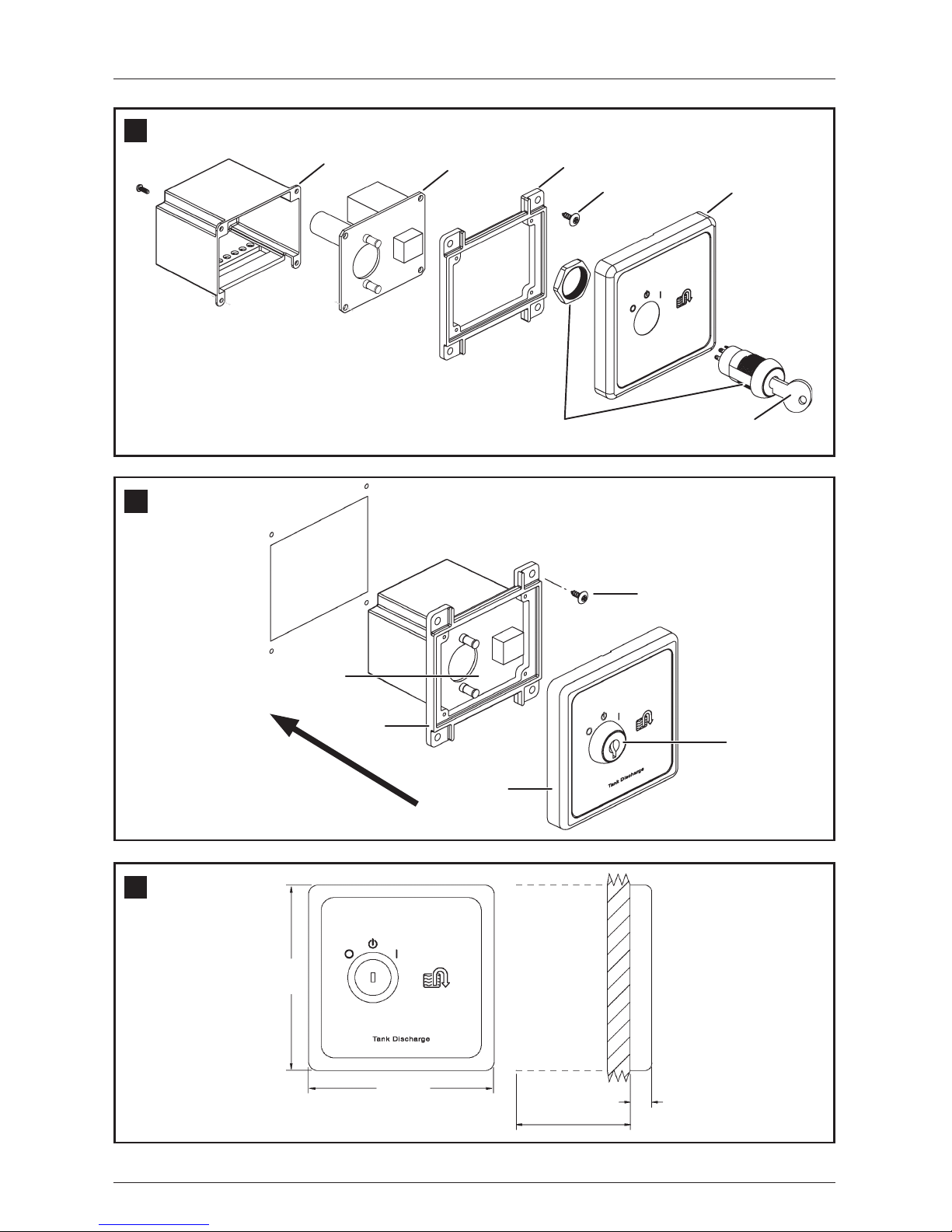
4 Components
Items in fig.
1 page 2
Description Item Number (Europe / North America)
1 Replacement key 860003853110362 / 385311036
2 Switch assembly 860003853116104 / 385311610
3 Panel cover 860003853116112 / 385311611
4 #6 fastener 860003853116120 / 385311612
5 Mounting frame 860003853116138 / 385311613
6 Circuit assembly
860003853116146 / 385311614 – 12 V DC
860003853116153 / 385311615 – 24 V DC
7 Circuit assembly housing 860003853116161 / 385311616
1
5 Specifications
5.1 Materials
3.3 Features
Secure discharge pump control. Key-operated switch provides convenient means to secure
discharge pump operation without use of padlocks or other mechanical fasteners.
Helps prevent pump burn-out. Activated panel light indicates when discharge pump is operating.
Reminds operator to shut off pump when tank discharge is complete.
Automatic pump shut-off with DTM04 tank monitor system. Discharge pump stops when tank level
drops below “Empty” level probe (g. 6 4, page 4).
Simplifies plumbing system. Eliminates wye valves, seacocks and vented loops of multiple
toilet systems.
5.2 Electrical Current Draw (panel only)
Panel frame and mounting frame: ABS Panel surface: Polycarbonate resin
Circuit assembly housing: High-density polyethylene
6
Specications subject to change without notice.
Caution!
Operator must know local regulations for emptying a holding tank.
Page 7

7
6 Installation
1. Select panel location away from direct contact with
water and oil.
2. Conrm clearance for wire connections behind wall,
hull liner or bulkhead.
3. Using control panel template (g. 8 , page 11), cut out
panel access hole (E, F) and drill fastener holes (G).
4. With electrical power off, route 14-gauge stranded copper
wire from power source, through discharge pump circuit
breaker or fuse (not provided), to panel location. Route
additional wire according to diagram on page 3 or 4
(see wiring diagram keys below), depending on your
application, to panel location. Make sure wires extend
out through access hole.
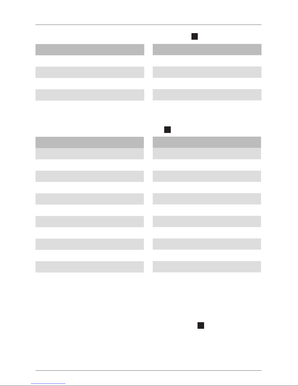
5. Make proper wiring connections to wires extending from
bottom of circuit assembly (g. 2 4, page 2).
6. Remove panel cover (g. 2 1, page 2) from mounting
frame (2) by carefully pulling them apart. Make sure wires
between key switch (3) and circuit assembly (4) remain
attached. (Key pin 1 – red; pin 2 – brown; pin 7 – blue.)
7. Install mounting frame to wall with four fasteners (5).
8. Tuck key switch wires into circuit assembly housing,
and push panel cover onto mounting frame until it
locks into place.
9. Turn on electrical power.
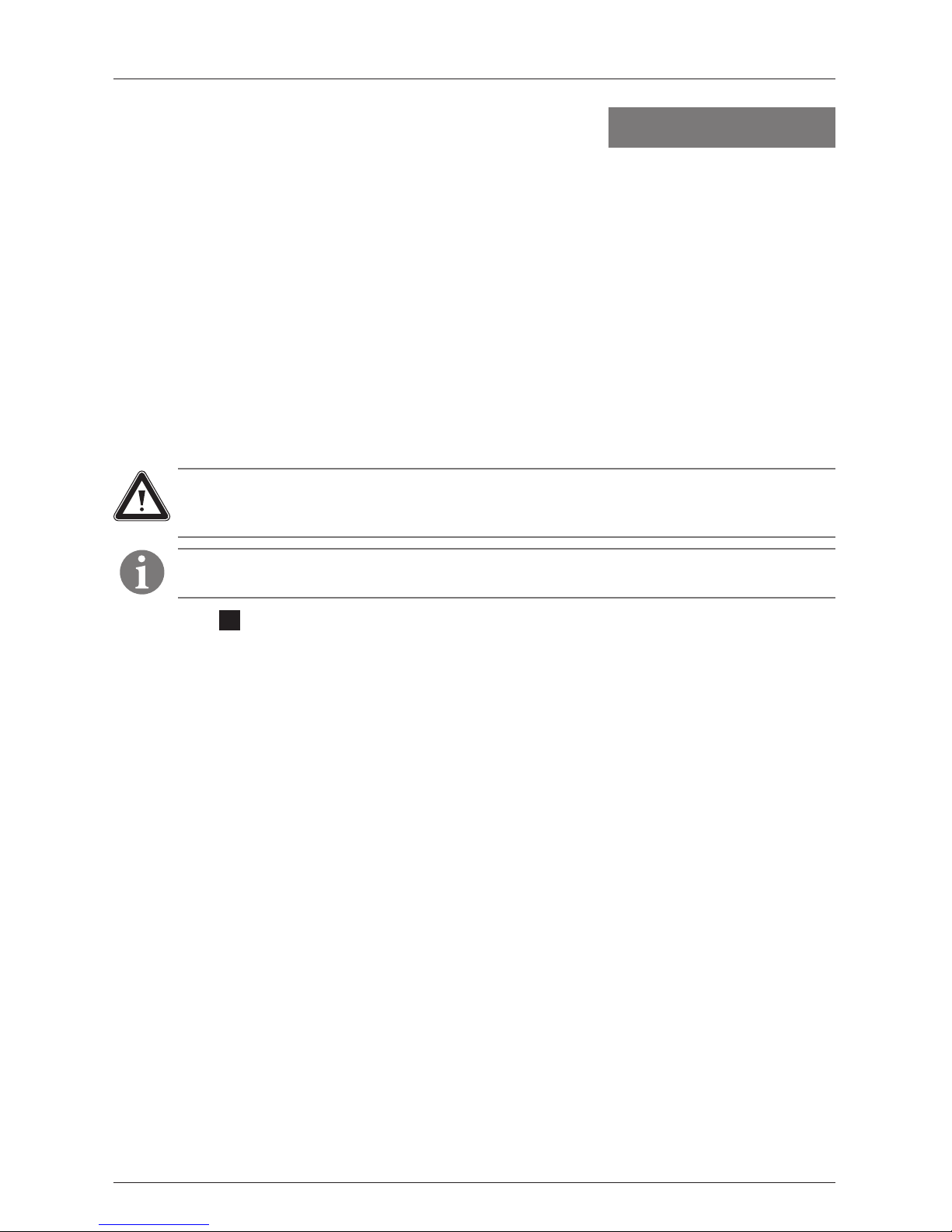
6.1 Tank Discharge Control Panel (g. 2 , page 2)
Control Panel Template
Dimensions (g. 8 , page 11)
2
Dometic Tank Discharge Control Specifications
Caution!
Do not install DTD control panel in an atmosphere with potentially flammable or
explosive vapors.
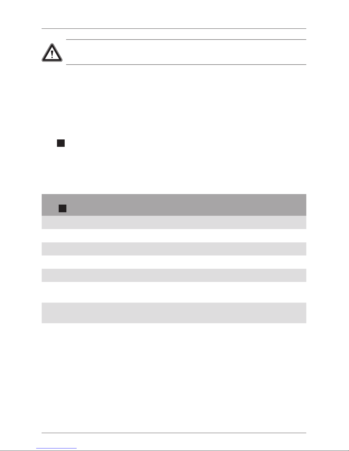
Ref. Dimension
A 83 mm (3.25 in.)
B 83 mm (3.25 in.)
C 67 mm (2.63 in.)
D 67 mm (2.63 in.)
E 55 mm (2.16 in.)
F 68 mm (2.69 in.)
G 2 mm (0.10 in.) dia.
H Cut-out area.
Allow 51 mm (2 in.)
clearance behind wall.
8
8
2
2
ISO8846; EMC Directive 2004/108/EC
5.4 Approvals
5.3 Dimensions (g. 3 , page 2)
Ref. Dimension
A 83 mm (3.25 in.)
B 83 mm (3.25 in.)
3
Ref. Dimension
C 51 mm (2 in.) clearance behind wall
D 10 mm (0.38 in.)
Maximum relay rating for 12 or 24 V DC discharge pump: 20 amps.
Float Switch Rating: 20 watts with resistive load (when used with DTM04 system).
Page 8
8
Dometic Tank Discharge ControlInstallation
7.1 OPTION 1: DTD01 discharge control panel only (g. 4 , page 3)
1. When boat is in unrestricted waters and pump-out is desired, insert key into switch and turn to
momentary “Start” position (1).
2. Allow key to rebound to “Pump On” position (2). Green light indicates that pump is running.
3. When pump-out is complete, turn key to “Off” position (3) and remove key from switch.
4
7 Operation
6.3 Key to DTD01-DTM04 system wiring (g. 7 , page 4)
Ref. Description
A DTD01 control panel
B Discharge pump
C DTM04 indicator panel
D Wastewater tank
E 12 or 24 V DC
F V DC ground
G Discharge pump circuit breaker or fuse
H 12 V DC
I 24 V DC
J 1-amp circuit breaker or fuse
K Toilet system circuit breaker or fuse
7
Ref. Description
L + V DC to electric toilet system
M Full level probe
N Mid level probe
O Low/Empty level probe
P Red
Q Black
R Brown
S Green
T Blue
U Yellow
V Orange
6.2 Key to DTD01 - discharge pump system wiring (g. 5 , page 3)
Ref. Description
A DTD01 control panel
B Discharge pump
C 12 or 24 V DC
D V DC ground
5
Ref. Description
E Discharge pump circuit breaker or fuse
F Red
G Black
H Brown
1. Use 14 gauge or larger diameter standard copper wire.
2. Maximum discharge pump circuit breaker or fuse rating: 20 amps.
1. Heavy line indicates 14 gauge or larger stranded copper wire is required.
2. Other wire can be 18 gauge stranded copper wire or larger.
3. Maximum discharge pump circuit breaker or fuse rating: 20 amps.
Page 9

9
Dometic Tank Discharge Control Warranty and Product Liability
7.2 OPTION 2: DTD01 discharge control panel with DTM04 tank monitor system
(g. 6 , page 4)
1. When the Dometic Tank Monitor panel reads “Full” (3) and boat is in unrestricted waters, insert key
into switch and turn to momentary “Start” position (1).
2. Allow key to rebound to “Pump On” position (2). Green light indicates that pump is running.
3. When pump-out is complete and Tank Monitor panel reads “Empty” (4), pump will automatically
shut off and green light will shut off. Turn key to “Off” position and remove key from switch any time
after pump-out is complete to secure pump.
6
Caution!
Do not allow discharge pump to operate for an extended period of time when there is no
discharge from holding tank. Damage to pump may result.
Europe:
Warranty and Customer Service
Warranty arrangements are in accordance with EC Directive 44/1999/CE and the normal conditions
applicable for the country concerned. For warranty or other service, please contact our Dometic/
Waeco Service department listed elsewhere in this manual. Any damage due to improper use is not
covered by the warranty.
The warranty does not cover any modications to the product or the use of non-original Dometic parts;
the warranty does not apply if the installation and operating instructions are not adhered to and no
liability shall be entertained.
Product Liability
Product liability of Dometic Group and its subsidiary companies does not include damages which
may arise from: faulty operation; improper alterations or intervention in the equipment; adverse
effects from the environment which may impact the equipment itself or the direct vicinity of the
equipment or persons in the area.
To obtain warranty service, rst contact your local dealer from whom you purchased this product or go
to http://www.dometic.com for a dealer near you.
8 Warranty and Product Liability
Caution!
Operator must know local regulations for emptying a holding tank.
Page 10

10
Dometic Tank Discharge ControlWarranty and Product Liability
® Registered; ™ Trademark of Dometic Corporation
North America and Rest of the World:
Manufacturer’s One-Year Limited Warranty
Dometic Corporation, Sanitation Division warrants to the original purchaser only that this product, if
used for personal, family or household purposes, is free from defects in material and workmanship for
a period of one year from the date of purchase.
If this Dometic product is placed in commercial or business use, it will be warranted to the original
purchaser only to be free of defects in material and workmanship for a period of ninety (90) days
from the date of purchase.
Dometic reserves the right to replace or repair any part of this product that proves, upon inspection
by Dometic, to be defective in material or workmanship. All labor and transportation costs or charges
incidental to warranty service are to be borne by the purchaser-user.
EXCLUSIONS
IN NO EVENT SHALL DOMETIC BE LIABLE FOR INCIDENTAL OR CONSEQUENTIAL DAMAGES,
FOR DAMAGES RESULTING FROM IMPROPER INSTALLATION, OR FOR DAMAGES CAUSED BY
NEGLECT, ABUSE, ALTERATION OR USE OF UNAUTHORIZED COMPONENTS. ALL IMPLIED WARRANTIES, INCLUDING ANY IMPLIED WARRANTY OF MERCHANTABILITY OR FITNESS FOR ANY
PARTICULAR PURPOSE, ARE LIMITED TO A PERIOD OF ONE YEAR FROM DATE OF PURCHASE.
IMPLIED WARRANTIES
No person is authorized to change, add to, or create any warranty or obligation other than that set
forth herein. Implied warranties, including those of merchantability and tness for a particular purpose,
are limited to one (1) year from the date of purchase for products used for personal, family or household purposes, and ninety (90) days from the date of purchase for products placed in commercial or
business use.
OTHER RIGHTS
Some states do not allow limitations on the duration of an implied warranty and some states do not
allow exclusions or limitations regarding incidental or consequential damages; so, the above limitations may not apply to you. This warranty gives you specic legal rights, and you may have other rights
which vary from state to state.
To obtain warranty service, rst contact your local dealer from whom you purchased this product or go
to http://www.dometic.com for a dealer near you.
Page 11

11
Dometic Tank Discharge Control Installation template
8
A
C
H
G
F
B D E
Page 12

12
Dometic Tank Discharge Control
Installation template
Page 13
13
1 Hinweise zur Benutzung der Einbauanleitung..................................... 13
2 Grundlegende Sicherheitshinweise ............................................. 13
3 Vorgesehene Verwendung................................................ 13 - 14
4 Komponenten ............................................................. 14
5 Spezikationen ........................................................ 14 - 15
6 Installation ............................................................ 15 - 17
7 Bedienung ................................................................ 17
8 Garantie und Produkthaftung ............................................. 17 - 18
1 Hinweise zur Benutzung der Einbauanleitung
Hinweis
Ergänzende Informationen zur Bedienung des Gerätes.
Abb. 1, Seite 2 : Bezeichnet ein Element in einer Illustration. In diesem Beispiel
Element 1 in Abbildung 2 auf Seite 2.
2
Achtung!
Sicherheitshinweis: Nichtbeachtung kann zu Materialschäden führen und die Funktion des
Gerätes beeinträchtigen.
DE
Inhalt
Entsorgungssteuerung Dometic-Tank Hinweise zur Benutzung der Einbauanleitung
2 Grundlegende Sicherheitshinweise
Der Hersteller übernimmt keine Haftung für Schäden aufgrund von
• Montage- oder Anschlussfehlern
• Schäden am Gerät durch mechanische Einwirkung
• Modikationen am Gerät ohne ausdrückliche Genehmigung des Herstellers
• Verwendung für andere als die in der Anleitung beschriebenen Zwecke
3 Vorgesehene Verwendung
3.1 OPTION 1: Nur Bedienfeld für Entsorgungssteuerung DTD01
Auf dem DTD-Bedienfeld für die Tankentsorgungssteuerung bendet sich ein Schlüsselschalter, mit
dem eine Absaugpumpe zur Leerung eines Schmutzwassertanks eingeschaltet wird. Das DTD01 kann
mit praktisch jeder elektrischen Absaugpumpe verwendet werden, die mit derselben Nennspannung
arbeitet (12 V DC oder 24 V DC).
3.2 OPTION 2: Bedienfeld für Entsorgungssteuerung DTD01 mit
Tanküberwachungssystem DTM04
In Verbindung mit dem Tanküberwachungssystem Dometic DTM04 schaltet das DTD-Bedienfeld für die
Tankentsorgungssteuerung die Absaugpumpe automatisch ab, wenn der Schmutzwassertank leer ist.
Page 14
14
Entsorgungssteuerung Dometic-TankVorgesehene Verwendung
4 Komponenten
Teile in Abb.
. , Seite 2
Beschreibung Artikelnummer (Europa / Nordamerika)
1 Ersatzschlüssel 860003853110362 / 385311036
2 Schlüsselbaugruppe 860003853116104 / 385311610
3 Bedienfeldabdeckung 860003853116112 / 385311611
4 Nr.6 Befestigungselement 860003853116120 / 385311612
5 Montagerahmen 860003853116138 / 385311613
6 Schaltkreisbaugruppe
860003853116146 / 385311614 – 12 V DC
860003853116153 / 385311615 – 24 V DC
7
Gehäuse für
Schaltkreisbaugruppe
860003853116161 / 385311616
1
5 Spezifikationen
5.1 Materialien
3.3 Merkmale
Sichere Absaugpumpensteuerung. Bequeme Möglichkeit zur Absicherung des Absaugpumpenbetriebs ohne Vorhängeschloss oder andere mechanische Befestigungsmittel dank Schlüsselschalter.
Hilft, ein Heißlaufen der Pumpe zu vermeiden. Aktivierte Bedienfeldleuchte signalisiert den Betrieb
der Absaugpumpe. Erinnert den Bediener daran, die Pumpe abzuschalten, wenn die Entleerung des
Tanks abgeschlossen ist.
Automatische Pumpenabschaltung in Verbindung mit dem Tanküberwachungssystem DTM04.
Die Absaugpumpe stoppt, wenn der Tankfüllstand unter die Füllstandsmarke “Leer” fällt.
(Abb. 4, Seite 4)
Vereinfacht das Rohrleitungssystem. Vermeidet Y-Ventile, Flutventile und Entlüftungsbögen bei
Systemen mit mehreren Toiletten.
Bedienfeldrahmen und Montagerahmen: ABS Bedienfeldoberfläche: Polycarbonatharz
Gehäuse für Schaltkreisbaugruppe: Hochdruck-Polyethylen
6
Achtung!
Der Betreiber muss die örtlichen Bestimmungen zum Leeren eines
Schmutzwassertanks beachten.
Page 15
15
6 Installation
1. Wählen Sie den Einbauort des Bedienfelds so, dass
es nicht direkt mit Wasser oder Öl in Berührung
kommen kann.
2. Stellen Sie sicher, dass hinter Wand, Verkleidung oder
Schott Raum für Kabelverbindungen vorhanden ist.
3. Verwenden Sie die Bedienfeld-Schablone (Abb. ,
Seite 11), um das Loch für das Bedienfeld auszuschneiden und die Befestigungslöcher zu bohren.
4. Legen Sie bei ausgeschalteter Stromversorgung eine
Kupferlitze mit einem Querschnitt von 2,5 mm2 von
der Stromquelle über einen Leistungsschalter oder
eine Sicherung (nicht im Lieferumfang enthalten)
zum Einbauort des Bedienfelds. Verlegen Sie weitere
Kabel gemäß dem Schaltplan auf Seite 3 oder 4 (siehe
Schlüssel zu Schaltplänen unten) und entsprechend
Ihrem Anwendungsfall zum Einbauort des Bedienfelds.
Längen Sie die Kabel so ab, dass ihre Enden aus dem
Loch für das Bedienfeld herausragen.
6.1 Bedienfeld für Tankentsorgungssteuerung (Abb. 2 , Seite 2)
Abmessungen der BedienfeldSchablone (Abb. , Seite 11)
2
Entsorgungssteuerung Dometic-Tank Spezifikationen
Achtung!
Installieren Sie das DTD-Bedienfeld nicht in Bereichen mit potenziell entflammbaren
oder explosiven Dämpfen.
Ref. Abmessungen
A 83 mm (3,25 Zoll)
B 83 mm (3,25 Zoll)
C 67 mm (2,63 Zoll)
D 67 mm (2,63 Zoll)
E 55 mm (2,16 Zoll)
F 68 mm (2,69 Zoll)
G 2 mm (0,10 Zoll) Durchmesser
H
51 mm ( 2 Zoll) Mindestabstand
hinter Wand
Systemspannung Pumpe aus (A) Pumpe ein (A)
12 V DC 0 0,16
24 V DC 0 0,095
8
8
5.2 Stromaufnahme (nur Bedienfeld)
ISO 8846; EMV-Richtlinie 2004/108/EG
5.4 Zulassungen
5.3 Abmessungen (Abb. 3 , Seite 2)
Ref. Abmessungen
A 83 mm (3,25 Zoll)
B 83 mm (3,25 Zoll)
3
Ref. Abmessungen
C 51 mm (2 Zoll) Mindestabstand hinter Wand
D 10 mm (0,38 Zoll)
Technische Daten können ohne vorherige Ankündigung geändert werden. Maximaler Relais-Schaltstrom für Absaugpumpe 12 V oder 24 V DC: 20 A. Schwimmerschalter-Nennwert: 20 Watt mit ohmscher
Last (bei Verwendung mit DTM04-System).
Page 16

16
Entsorgungssteuerung Dometic-TankInstallation
6.3 Legende zum Schaltplan DTD01-DTM04 (Abb. 7 , Seite 4)
Ref. Beschreibung
A DTD01-Bedienfeld
B Abwasserpumpe
C Anzeigefeld DTM04
D Schmutzwassertank
E 12 oder 24 V DC
F V DC Masse
G
Leistungsschalter oder Sicherung
für Absaugpumpe
H 12 V DC
I 24 V DC
J 1-A-Leistungsschalter oder -Sicherung
K
Leistungsschalter oder Sicherung für
Toilettensystem
7
Ref. Beschreibung
L + V DC zum elektrischen Toilettensystem
M Füllstandssonde Voll
N Füllstandssonde Mittel
O Füllstandsonde Niedrig/Leer
P rot
Q schwarz
R braun
S grün
T blau
U gelb
V orange
6.2 Legende zurm Schaltplan des Absaugpumpsystems DTD01 (Abb. , Seite 3)
Ref. Beschreibung
A DTD01-Bedienfeld
B Abwasserpumpe
C 12 oder 24 V DC
D V DC Masse
5
Ref. Beschreibung
E
Leistungsschalter oder Sicherung
für Absaugpumpe
F rot
G schwarz
H braun
1. Kupferlitze mit einem Querschnitt von mindestens 2,5 mm2 verwenden.
2. Maximaler Nennwert für Leistungsschalter oder Sicherung Absaugpumpe: 20 A.
5. Verbinden Sie die Enden fest mit den Enden der Kabel, die aus der Unterseite der Schaltkreisbaugruppe herausragen (Abb. 4, Seite 2).
6. Entfernen Sie die Abdeckung des Bedienfelds (Abb. 1, Seite 2) vom Montagerahmen (2), indem
Sie die beiden Teile vorsichtig auseinanderziehen. Achten Sie darauf, dass die Verbindungen der
Kabel zwischen Schlüsselschalter (3) und Schaltkreisbaugruppe (4) erhalten bleiben. (Schlüsselkontakt 1 – rot; Kontakt 2 – braun; Kontakt 7 – blau)
7. Bringen Sie den Montagerahmen mit vier Schrauben (5) an der Wand an.
8. Stecken Sie die Kabel vom Schlüsselschalter in das Baugruppengehäuse und drücken sie die
Bedienfeldabdeckung auf den Montagerahmen, bis sie einrastet.
9. Schalten Sie die Stromversorgung ein.
2
2
Page 17
17
Entsorgungssteuerung Dometic-Tank Installation
7.2 OPTION 2: Bedienfeld für Entsorgungssteuerung DTD01 mit Tanküberwac-
hungssystem DTM04 (Abb. , Seite 4)
1. Wenn der Dometic-Tankmonitor „Voll“ (3) anzeigt, sich Ihr Boot in freiem Gewässer bendet und Sie
das Schmutzwasser abpumpen möchten, stecken Sie den Schlüssel in den Schalter und drehen ihn
kurz in die Stellung „Start“ (1).
2. Lassen Sie den Schlüssel in die Stellung „Pump On“ (2) zurückfedern. Eine grüne Leuchte zeigt an,
dass die Pumpe läuft.
3. Wenn der Tank leergepumpt ist und der Tankmonitor„Leer“ (4) anzeigt, schaltet sich die Pumpe
automatisch ab und die grüne Leuchte erlischt. Drehen Sie den Schlüssel nach dem Abpumpen jedes Mal in die Stellung „Off“ und ziehen Sie den Schlüssel aus dem Schalter, um
die Pumpe abzusichern.
6
7.1 OPTION 1: Nur Bedienfeld für Entsorgungssteuerung DTD01 (Abb. , Seite 3)
1. Wenn sich Ihr Boot in freiem Gewässer bendet und Sie das Schmutzwasser abpumpen möchten,
stecken Sie den Schlüssel in den Schalter und drehen ihn kurz in die Stellung „Start“ (1).
2. Lassen Sie den Schlüssel in die Stellung „Pump On“ (2) zurückfedern. Eine grüne Leuchte zeigt an,
dass die Pumpe läuft.
3. Wenn der Tank leergepumpt ist, drehen Sie den Schlüssel in die Stellung „Off“ (3) und ziehen den
Schlüssel aus dem Schalter.
4
Achtung!
Lassen Sie die Pumpe nicht längere Zeit bei leerem Schmutzwassertank laufen. Dies
könnte zu Schäden an der Pumpe führen.
7 Bedienung
Europa:
Garantie und Kundendienst
Die Garantievereinbarungen entsprechen der EG-Direktive 44/1999/EG und die normalen Bedingungen gelten für das betreffende Land. Wenden Sie sich an die Dometic/Waeco Service-Abteilung, deren
Adresse Sie an anderer Stelle in diesem Handbuch nden, wenn Sie einen Garantiefall oder eine andere
Serviceleistung vereinbaren möchten. Alle Schäden aufgrund falscher oder missbräuchlicher Bedienung
werden von der Garantie nicht abgedeckt.
Von der Garantie werden keine Änderungen am Produkt oder die Verwendung von anderen Bauteilen als
den Dometic Originalteilen abgedeckt; die Garantie gilt nicht, wenn die Installations- oder Betriebsanweisungen nicht beachtet werden. In solchen Fällen wird jedwede Haftung durch den Hersteller abgelehnt.
8 Garantie und Produkthaftung
Achtung!
Der Betreiber muss die örtlichen Bestimmungen zum Leeren eines
Schmutzwassertanks beachten.
1. Dicke Linie steht für Kupferlitze mit Querschnitt von mindestens 2, 5 mm2.
2. Der Querschnitt der übrigen Litzen muss mindestens 1 mm2 betragen.
3. Maximaler Nennwert für Leistungsschalter oder Sicherung Absaugpumpe: 20 A.
Page 18

18
Entsorgungssteuerung Dometic-TankGarantie und Produkthaftung
Produkthaftung
Die Produkthaftung der Dometic Group und ihrer Niederlassungen umfasst keine Schäden, die
durch das Folgende entstehen: fehlerhafter Betrieb; ungeeignete Änderungen oder Eingriffe in die
Anlage; negative Umgebungsauswirkungen, die die Anlage selbst beeinträchtigen oder die direkte
Umgebung der Anlage oder Personen in diesem Bereich.
Wenn Sie eine Garantieleistung in Anspruch nehmen möchten, wenden Sie sich zuerst an Ihren
Fachhändler vor Ort, bei dem Sie das Produkt erworben haben oder informieren Sie sich im
Internet unter http://www.dometic.com über Händler in Ihrer Nähe.
® Eingetragenes ™ Warenzeichen der Dometic Corporation
Page 19

19
1 Remarques concernant ce mode d'emploi ....................................... 19
2 Consignes générales de sécurité .............................................. 19
3 Usage conforme ....................................................... 19 - 20
4 Composants .............................................................. 20
5 Spécications ......................................................... 20 - 21
6 Installation ............................................................ 21 - 23
7 Fonctionnement............................................................ 23
8 Garantie et Responsabilité pour le produit ................................... 23 - 25
1 Remarques concernant ce mode d'emploi
Remarque
Informations supplémentaires relatives à l'utilisation de l'appareil.
fig. 1, page 2 : Ceci désigne un élement d'un schéma. Dans cet exemple, l'item 1 du
schéma 2 sur la page 2.
2
Attention !
Consigne de sécurité : Le non-respect de cette consigne peut entraîner des dégâts
matériels et entraver le fonctionnement de l'appareil.
FR
Table des matières
Commande d'évacuation du réservoir Dometic Remarques concernant ce mode d'emploi
2 Consignes générales de sécurité
Le fabricant ne saurait être tenu responsable dans les cas suivants:
• Assemblage ou connections incorrects
• Appareil endommagé par des inuences mécaniques
• Modication de l'appareil sans l'autorisation écrite expresse du fabricant
• Utilisations autres que celles décrites dans le mode d'emploi
3 Usage conforme
3.1 OPTION 1 : panneau de commande d'évacuation DTD01 uniquement
Le panneau de commande d'évacuation du réservoir DTD fournit un commutateur à clé permettant
d'activer une pompe d'évacuation qui vide le réservoir d'eaux usées. Le DTD01 peut a priori être utilisé
avec toutes les pompes électriques d'évacuation fonctionnant avec la même tension nominale (12 V CC
ou 24 V CC).
3.2 OPTION 2 : panneau de commande d'évacuation DTD01 avec système de
surveillance du réservoir DTM04
S'il est combiné avec le système de surveillance du réservoir Dometic DTM04, le panneau de
commande d'évacuation du réservoir DTD éteint automatiquement la pompe d'évacuation lorsque
le réservoir d'eaux usées est vide.
Page 20

20
Commande d'évacuation du réservoir DometicUsage conforme
4 Composants
Items dans la fig.
, page 2
Description
Numéro d'article
(Europe / Amérique du Nord)
1 Double de clé 860003853110362 / 385311036
2 Assemblage du commutateur 860003853116104 / 385311610
3 Cache du panneau 860003853116112 / 385311611
4 Dispositif de xation n° 6 860003853116120 / 385311612
5 Cadre de montage 860003853116138 / 385311613
6 Assemblage du circuit
860003853116146 / 385311614 – 12 V CC
860003853116153 / 385311615 – 24 V CC
7
Bâti de l'assemblage
du circuit
860003853116161 / 385311616
1
5 Spécifications
5.1 Matériaux
3.3 Fonctions
Commande sécurisée de la pompe d'évacuation. Le commutateur à clé fournit des moyens pratiques de sécuriser le fonctionnement de la pompe d'évacuation sans utiliser de cadenas ou d'autres
éléments mécaniques de xation.
Permet d'éviter une surchauffe de la pompe. L'activation du témoin lumineux du panneau indique le
fonctionnement de la pompe. Cela rappelle à l'opérateur d'éteindre la pompe lorsque la vidange du
réservoir est terminée.
Extinction automatique de la pompe avec le système de surveillance du réservoir DTM04. La
pompe d'évacuation s'arrête lorsque le niveau du réservoir passe en dessous le détecteur de niveau
“Vide” (g. 6 4, page 4).
Simplifie le système de tuyauterie. Plus besoin de vannes en étoiles, de robinets et de boucles de
ventilation présents dans de nombreux systèmes de toilettes.
Cadre du panneau et cadre de montage: ABS
Surface du panneau : résine polycarbonate
Bâti de l'assemblage du circuit : polyéthylène haute densité
6
Attention!
L'opérateur se doit de connaître les réglementations locales concernant la vidange des
réservoirs d'eaux usées.
Page 21

21
6 Installation
1. Ne montez pas le panneau de commande à proximité
de l'eau ou d'huiles.
2. Vériez les espaces derrière le mur, le rembourrage de
la coque ou la cloison pour la connexion des câbles.
3. En utilisant le gabarit du panneau de commande (g.
, page 11), découpez le trou d'accès au panneau
(E, F) et percez les trous des dispositifs de xation (G).
4. Après avoir éteint le courant électrique, connectez
l'endroit choisi pour le panneau à la source de courant
électrique avec du l de cuivre tressé épaisseur 14, en
le faisant passer par un fusible ou le disjoncteur du circuit de la pompe d'évacuation (non fourni). Selon votre
application, posez un câble supplémentaire jusqu'à
l'emplacement de montage du panneau en vous conformant au schéma des pages 3 ou 4 (voir ci-dessous
la légende du schéma de câblage). Assurez-vous que
les câbles passent à travers le trou d'accès.
6.1 Panneau de commande d'évacuation du réservoir (g. 2 , page 2)
Dimensions du gabarit du panneau
de commande (g. 8 , page 11)
2
Commande d'évacuation du réservoir Dometic Spécifications
Attention !
Ne pas monter le panneau de commande DTD dans un environnement potentiellement inflammable ou contenant des vapeurs explosives.
Réf. Dimension
A 83 mm
B 83 mm
C 67 mm
D 67 mm
E 55 mm
F 68 mm
G 2 mm de diamètre
H
Espace minimum de 51 mm
derrière le mur.
Tension du système Pompe éteinte (A) Pompe allumée (A)
12 V CC 0 0,16
24 V CC 0 0,095
8
8
5.2 Courant électrique (panneau uniquement)
ISO8846; Directive EMC 2004/108/EC
5.4 Approbations
5.3 Dimensions (g. , page 2)
Réf. Dimension
A 83 mm
B 83 mm
3
Réf. Dimension
C Espace minimum de 51 mm derrière le mur.
D 10 mm
Spécications sous réserve de modications sans préavis. Valeur nominale maximale du relais pour
pompe d'évacuation 12 ou 24 V CC : 20 A. Valeur nominale interrupteur à otteur : 20 watts avec charge
résistive (en cas d'utilisation avec le système DTM04).
Page 22

22
Commande d'évacuation du réservoir DometicInstallation
6.3 Légende du câblage du système DTD01-DTM04 (g. 7 , page 4)
Réf. Description
A Panneau de commande DTD01
B Pompe d'évacuation
C Panneau indicateur DTM04
D Réservoir d'eaux usées
E 12 ou 24 V CC
F V CC terre
G
Disjoncteur du circuit de la pompe
d’évacuation ou fusible
H 12 V CC
I 24 V CC
J Disjoncteur de circuit ou fusible 1 A
K
Disjoncteur de circuit du système de toilettes ou fusible
7
Réf. Description
L + V CC vers le système électrique des toilettes
M Détecteur de niveau plein
N Détecteur de niveau intermédiaire
O Détecteur de niveau bas/vide
P rouge
Q noir
R marron
S vert
T bleu
U jaune
V orange
6.2 Légende du câblage du système de la pompe d'évacuation-DTD01 (g. , page 3)
Réf. Description
A Panneau de commande DTD01
B Pompe d'évacuation
C 12 ou 24 V CC
D V CC terre
5
Réf. Description
E
Disjoncteur du circuit de la pompe
d'évacuation ou fusible
F rouge
G noir
H marron
1. Utilisez du l de cuivre tressé épaisseur 14 ou plus.
2. Valeur nominale maximale du disjoncteur du circuit de la pompe d'évacuation ou du fusible : 20 A.
5. Effectuez les connexions adéquates avec les câbles sortant en bas de l'assemblage du circuit
(g. 2 4, page 2).
6. Détachez le cache du panneau (g. 2 1, page 2) du cadre de montage (2) en les séparant avec
précaution. Assurez-vous que les câbles entre le commutateur à clé (3) et l'assemblage du circuit
(4) restent branchés. (Légende : broche 1 – rouge ; broche 2 – marron ; broche 7 – bleue.)
7. Installez le cadre de montage au mur à l'aide de quatre dispositifs de xation (5).
8. Insérez les câbles de l'interrupteur à clé dans le bâti de l'assemblage du circuit et appuyez le
cache du panneau sur le cadre de montage jusqu'à ce qu'il s'enclenche.
9. Mettez le panneau sous tension.
2
2
Page 23

23
Commande d'évacuation du réservoir Dometic Installation
7.2 OPTION 2 : panneau de commande d'évacuation DTD01 avec système de
surveillance du réservoir DTM04 (g. 6 , page 4)
1. Lorsque le panneau de surveillance du réservoir Dometic indique “Plein” (3) et que le bateau se
trouve dans des eaux non soumises à restrictions, insérez la clé dans le commutateur et tournez-la
en position “Démarrage” momentané (1).
2. Laissez la clé revenir en position “Pompe Marche” (2). La lumière verte indique que la pompe
est en service.
3. Lorsque le pompage est terminé et que le panneau de surveillance du réservoir indique “Vide” (4),
la pompe s'éteint automatiquement et la lumière verte aussi. Tournez la clé en position “Arrêt” (3) et
retirez la clé du commutateur une fois que le pompage est terminé, an de sécuriser la pompe.
6
7.1 OPTION 1 : panneau de commande d'évacuation DTD01 uniquement (g. 4 , page 3)
1. Lorsque le bateau se trouve dans des eaux non soumises à restrictions et que vous souhaitez
effectuer un pompage, insérez la clé dans le commutateur et tournez-la en position “Démarrage”
momentané (1).
2. Laissez la clé revenir en position “Pompe Marche”(2). La lumière verte indique que la pompe
est en service.
3. Wenn der Tank leergepumpt ist, drehen Sie den Schlüssel in die Stellung „Off“ (3) und ziehen den
Schlüssel aus dem Schalter.
4
Attention !
Ne laissez pas la pompe d'évacuation fonctionner pendant une période prolongée alors que
rien n'est évacué du réservoir des eaux usées. Cela risquerait d'endommager la pompe.
7 Fonctionnement
Europe:
Garantie et service après-vente
Les conditions de la garantie correspondent à la directive 44/1999/CE et aux conditions normales
applicables dans le pays concerné. Pour la garantie ou un autre service, veuillez contacter notre service
après-vente Dometic/Waeco dont la liste gure dans le manuel. Tout dommage dû à une utilisation non
conforme n'est pas couvert par la garantie.
La garantie ne couvre pas les modications apportées au produit ou lutilisation dautres pièces que les
pièces Dometic dorigine; la garantie ne sapplique pas si les instructions dinstallation et dutilisation ne
sont pas respectées et aucune responsabilité ne peut être admise.
8 Garantie et Responsabilité pour le produit
Attention !
L'opérateur se doit de connaître les réglementations locales concernant la vidange des
réservoirs d'eaux usées.
1. Une ligne épaisse indique qu'il faut un câble de cuivre tressé de 14 mm ou plus.
2. Les autres câbles peuvent être des câbles de cuivre tressé de 18 mm ou plus.
3. Valeur nominale maximale du disjoncteur de la pompe d'évacuation ou du fusible : 20 A.
Page 24

24
Commande d'évacuation du réservoir DometicGarantie et Responsabilité pour le produit
Responsabilité pour le produit
La responsabilité du groupe Dometic et de ses liales pour le produit ninclut pas les dommages
éventuellement provoqués par: une utilisation impropre; des modications impropres ou des
interventions sur le matériel; des effets nocifs de lenvironnement pouvant avoir un impact sur le
matériel lui-même ou le matériel et les personnes à proximité directe dans cette zone.
Pour obtenir le service de garantie, veuillez contacter dans un premier temps le revendeur chez
lequel vous avez acheté ce produit ou consulter le site http://www.dometic.com an de trouver un
revendeur près de chez vous.
Amérique du Nord et reste du monde:
Garantie du fabricant limitée à un an et à cinq ans
Le secteur Assainissement du groupe Dometic garantit à lacheteur dorigine uniquement que ce
produit, sil est utilisé à des ns personnelles, familiales et dans le cadre privé, est exempt de défauts de matériau et de fabrication pour une période dun an à compter de la date dachat.
Si ce produit Dometic est utilisé à des ns commerciales, nous garantissons à lacheteur dorigine
exclusivement que ce produit est exempt de défauts de matériau et de fabrication pour une période de quatre-vingt-dix (90) jours à compter de la date dachat.
Dometic se réserve le droit de remplacer ou réparer toute pièce de ce produit savérant, après
inspection par Dometic, présenter des défauts de matériau ou de fabrication. Tous les coûts de
laboratoire et de transport ou les frais relatifs au service de garantie sont à la charge de lacheteurutilisateur.
EXCLUSIONS
DOMETIC NE PEUT EN AUCUN CAS ÊTRE TENU RESPONSABLE DE DOMMAGES ACCIDENTELS OU CONSÉCUTIFS, DE DOMMAGES RÉSULTANT DUNE INSTALLATION IMPROPRE OU DE
DOMMAGES CAUSÉS PAR LA NÉGLIGENCE, LUTILISATION ABUSIVE, LALTÉRATION OU
LUSAGE DE COMPOSANTS NON AUTORISÉS. TOUTES LES GARANTIES IMPLICITES, Y
COMPRIS LA GARANTIE DE VALEUR MARCHANDE ET LA GARANTIE DAPTITUDE POUR UN
USAGE PARTICULIER, SONT LIMITÉES À UNE PÉRIODE D’UN AN À COMPTER DE LA DATE
DACHAT.
GARANTIES IMPLICITES
Il est strictement interdit de modier les garanties ou obligations telles quelles sont xées ici, dy
faire des ajouts ou den créer dautres. Les garanties implicites, y compris la garantie de valeur
marchande et la garantie daptitude pour un usage particulier, sont limitées à une période dun (1)
an à compter de la date dachat pour les produits utilisés à des ns personnelles, familiales et dans
le cadre privé, et à une période de quatre-vingt-dix (90) jours à compter de la date dachat pour les
produits utilisés à des ns commerciales.
AUTRES DROITS
Certains Etats ne permettent pas la limitation de la durée dune garantie implicite et certains Etats
ne permettent pas lexclusion ou la limitation des dommages accidentels ou consécutifs, de sorte
que la limitation ci-dessous peut ne pas vous concerner. Cette garantie vous confère des droits
légaux spéciques et vous pouvez bénécier dautres droits qui varient dun Etat à lautre.
Pour obtenir le service de garantie, veuillez contacter dans un premier temps le revendeur chez
lequel vous avez acheté ce produit ou consulter le site http://www.dometic.com an de trouver un
revendeur près de chez vous.
Page 25

25
Commande d'évacuation du réservoir Dometic Garantie et Responsabilité pour le produit
Marque déposée, Dometic Corporation
Page 26

26
Control de descarga del depósito DometicNotas relativas al uso de este manual
1 Notas relativas al uso de este manual........................................... 26
2 Instrucciones generales de seguridad........................................... 26
3 Uso previsto........................................................... 26 - 27
4 Componentes ............................................................. 27
5 Especicaciones ....................................................... 27 - 28
6 Instalación ............................................................ 28 - 30
7 Funcionamiento............................................................ 30
8 Garantía y Responsabilidad sobre el producto................................ 30 - 32
1 Notas relativas al uso de este manual
Nota
Información suplementaria relativa al manejo del dispositivo.
Fig. 1, pág. 2 : se reere a un elemento de un dibujo. En este ejemplo, elemento 1 en
la gura 2 de la pág. 2.
2
¡Precaución!
Indicación de seguridad: si no respeta esta indicación, se pueden producir daños mate-
riales y perjudicar el funcionamiento del dispositivo.
ES
Índice
2 Instrucciones generales de seguridad
El fabricante no se hará responsable de las reclamaciones por daños resultantes de alguno de los
siguientes casos:
• Montaje o conexión incorrectos
• Daños producidos por inuencias mecánicas
• Modicaciones efectuadas sin la autorización expresa por escrito del fabricante
• Uso para nes distintos de los descritos en el manual de funcionamiento
3 Uso previsto
3.1 OPCIÓN 1: sólo panel de control de descarga DTD01
El panel de control de descarga del depósito DTD dispone de un interruptor con llave para activar una
bomba de descarga que vaciará un depósito de retención. El DTD01 puede utilizarse con prácticamente
cualquier bomba eléctrica de descarga que funcione con la misma tensión nominal (12 V CC o 24 V CC).
3.2 OPCIÓN 2: panel de control de descarga DTD01 con sistema de control
de depósitos DTM04
Cuando esté integrado en el sistema de control de depósitos DTM04 de Dometic, el panel de control
de descarga del depósito DTD apagará automáticamente la bomba de descarga cuando el depósito de
retención esté vacío.
Page 27

27
Control de descarga del depósito Dometic Uso previsto
4 Componentes
Piezas en la
fig. , pág. 2
Descripción
N.° de artículo
(Europa / América del Norte)
1 Llave de repuesto 860003853110362 / 385311036
2 Unidad de interruptor 860003853116104 / 385311610
3 Cubierta del panel 860003853116112 / 385311611
4 #6 dispositivos de jación 860003853116120 / 385311612
5 Marco de montaje 860003853116138 / 385311613
6 Unidad de circuito
860003853116146 / 385311614 – 12 V CC
860003853116153 / 385311615 – 24 V CC
7
Alojamiento de la unidad
de circuito
860003853116161 / 385311616
1
5 Especificaciones
5.1 Materiales
3.3 Características
Control seguro de la bomba de descarga. El interruptor con llave suministra los medios convenientes para asegurar el funcionamiento de la bomba de descarga sin usar candados u otros dispositivos
de sujeción mecánicos.
Ayuda a prevenir que la bomba se funda. La luz del panel activada indica que la bomba de descarga está en funcionamiento. Recuerda al operario que apague la bomba cuando se haya completado la descarga del depósito.
Apagado automático de la bomba con el sistema de control de depósitos DTM04. La bomba de
descarga se detiene cuando el nivel del depósito cae por debajo de la sonda de nivel “Vacía”
(g. 4, pág. 4).
Simplifica el sistema de tuberías. Elimina las válvulas en Y, tomas de mar y circuitos de ventilación
aireados de los sistemas de inodoro múltiples.
Marco del panel y marco de montaje: ABS Superficie del panel: resina de policarbonato
Alojamiento de la unidad de circuito: polietileno de alta densidad
6
¡Precaución!
El usuario debe conocer las normas locales para vaciar un depósito de retención.
Page 28

28
Control de descarga del depósito DometicEspecificaciones
6 Instalación
1. Coloque el panel en un lugar donde no pueda entrar
en contacto directo con agua ni aceite.
2. Compruebe el espacio libre que hay para conexiones
de cable detrás de la pared, del mamparo o del forro
interior del casco.
3. Utilizando la plantilla del panel de control (g. 8 ,
pág. 11), recorte un agujero de acceso al panel (E, F)
y perfore agujeros de jación (G).
4. Con la alimentación eléctrica desconectada, lleve el
cable de cobre trenzado de calibre 14 desde la fuente
de alimentación, a través del disyuntor o fusible de la
bomba de descarga (no incluido en la entrega), hasta
el panel. Tienda el cable adicional según el diagrama
de la página 3 o 4 (véanse las leyendas del esquema
de conexiones más abajo), en función de su aplicación,
hasta el panel. Asegúrese de que los cables salgan a
través del agujero de acceso.
6.1 Panel de control de descarga del depósito (g. 2 , pág. 2)
Dimensiones de la plantilla del
panel de control (g. 8 , pág. 11)
2
¡Precaución!
No instale el panel de control DTD en una atmósfera que contenga vapores
potencialmente inflamables o explosivo.
Ref. Dimensión
A 83 mm (3,25 pulg.)
B 83 mm (3,25 pulg.)
C 67 mm (2,63 pulg.)
D 67 mm (2,63 pulg.)
E 55 mm (2,16 pulg.)
F 68 mm (2,69 pulg.)
G 2 mm (0,10 pulg.) diám.
H
51 mm (2 pulg.) espacio libre
mínimo detrás de la pared
Tensión del sistema Bomba apagada (A) Bomba encendida (A)
12 V CC 0 0,16
24 V CC 0 0,095
8
8
5.2 Diagrama de conexiones eléctricas (sólo panel)
ISO8846; directiva CEM 2004/108/CE
5.4 Homologaciones
5.3 Dimensiones (g. , pág. 2)
Ref. Dimensión
A 83 mm (3,25 pulg.)
B 83 mm (3,25 pulg.)
3
Ref. Dimensión
C
51 mm (2 pulg.) espacio libre mínimo
detrás de la pared
D 10 mm (0,38 pulg.)
Especicaciones sujetas a cambio sin previo aviso. Valor máximo de relé para una bomba de descarga
de 12 o 24 V CC: 20 amperios. Valor de interruptor otante: 20 vatios con carga resistiva (cuando se
utiliza con el sistema DTM04).
Page 29

29
Control de descarga del depósito Dometic Instalación
6.3 Leyenda para el cableado del sistema DTD01-DTM04 (g. 7 , pág. 4)
Ref. Descripcíon
A Panel de control DTD01
B Bomba de descarga
C Panel indicador DTM04
D Depósito de aguas residuales
E 12 o 24 V CC
F Masa V CC
G Disyuntor o fusible de la bomba de descarga
H 12 V CC
I 24 V CC
J Disyuntor o fusible de 1 amperio
K Disyuntor o fusible del sistema de inodoro
7
Ref. Descripcíon
L + V CC al sistema eléctrico de inodoro
M Sonda llenado completo
N Sonda llenado medio
O Sonda llenado bajo/vacía
P rojo
Q negro
R marrón
S verde
T azul
U amarillo
V anaranjado
6.2 Leyenda para DTD01 - cableado del sistema de la bomba de
descarga (g. 5 , pág. 3)
Ref. Descripcíon
A Panel de control DTD01
B Bomba de descarga
C 12 o 24 V CC
D Masa V CC
5
Ref. Descripcíon
E Disyuntor o fusible de la bomba de descarga
F rojo
G negro
H marrón
1. Utilice un cable de cobre trenzado de calibre 14 o superior.
2. Valor máximo del disyuntor o fusible de la bomba de descarga: 20 amperios.
5. Establezca conexiones de cable correctas a los cables que se extienden desde el fondo del la
unidad de circuito (g. 2 4, pág. 2).
6. Retire la cubierta del panel (g. 2 1, pág. 2) del marco de montaje (2) empujándola con cuidado
hacia fuera. Asegúrese de que los cables entre el interruptor de llave (3) y la unidad de circuito (4)
siguen unidos. (leyenda: clavija 1 – roja; clavija 2 – marrón; clavija 7 – azul).
7. Instale el marco de montaje en el muro con cuatro dispositivos de sujeción (5).
8. Introduzca los cables del interruptor de llave en el alojamiento de la unidad de circuito y empuje la
cubierta del panel sobre el marco de montaje hasta que encaje en su sitio.
9. Conecte la alimentación eléctrica.
2
2
Page 30

30
Control de descarga del depósito DometicInstalación
7.2 OPCIÓN 2: panel de control de descarga DTD01 con sistema de control de
depósitos DTM04 (g. 6 , pág. 4)
1. Cuando lea en el panel del control del depósito de Dometic “Lleno” (3) y la embarcación esté en
aguas no restringidas, introduzca la llave en el interruptor y gírela momentáneamente a la posición
“Inicio” (1).
2. Deje que la llave vuelva a la posición “Bomba encendida” (2). La luz verde indica que la bomba está
en funcionamiento.
3. Cuando nalice el bombeo y lea en el panel del control del depósito “Lleno” (4), la bomba se
apagará automáticamente y también la luz verde. Gire la llave a la posición “Apagada” y extraiga
la llave del interruptor una vez que se haya completado el bombeo para asegurar la bomba.
6
7.1 OPCIÓN 1: sólo panel de control de descarga DTD01 (g. 4 , pág. 3)
1. Si la embarcación está en aguas no restringidas y desea bombear, inserte la llave en el interruptor y
gírela momentáneamente a la posición “Inicio” (1).
2. Deje que la llave vuelva a la posición “Bomba encendida” (2). La luz verde indica que la bomba está
en funcionamiento.
3. Cuando nalice el bombeo, dirija la llave a la posición “Apagada” (3) y extráigala del interruptor.
4
¡Precaución!
No deje que la bomba de descarga funcione durante un largo periodo de tiempo cuando no
haya descarga desde el depósito de retención. Esto podría provocar daños en la bomba.
7 Funcionamiento
Europa:
Garantía y Servicio al Cliente
Los acuerdos de garantía se han tomado conforme a la directiva CE 44/1999/CE y las condiciones
normales aplicables al país en cuestión. Para cuestiones relativas a la garantía o a otros servicios,
póngase en contacto con el Departamento de Atención al Cliente que aparece listado en este
manual. La garantía no cubre ningún daño provocado por un uso indebido.
Esta garantía perderá su validez en el caso de que se hayan realizado modicaciones en el producto o de que se hayan utilizado piezas no originales de Dometic. Asimismo, tampoco se aplicará
en el caso de que no se hayan respetado las instrucciones de instalación y manejo, en cuayo caso
se declinará toda responsabilidad.
8 Garantía y Responsabilidad sobre el Producto
¡Precaución!
El usuario debe conocer las normas locales para vaciar un depósito de retención.
1. La línea en negrita indica la necesidad de un cable de cobre trenzado de calibre 14 o superior.
2. El otro cable puede ser de cobre trenzado de calibre 18 o superior.
3. Valor máximo del disyuntor o fusible de la bomba de descarga: 20 amperios.
Page 31

31
Control de descarga del depósito Dometic Garantía y Responsabilidad sobre el producto
Responsabilidad sobre el producto
La responsabilidad de Dometic Group y sus compañías subsidiarias no cubre daños provocados
por: man-ejo incorrecto, modicaciones o intervenciones indebidas en el equipo; efectos adversos
del entorno que puedan afectar al equipo o a las inmediaciones del mismo o a las personas que
se encuentren en la zona.
Para obtener el servicio de garantía, póngase en contacto con el distribuidor local a quien le
compró este producto o visite la página http://www.dometic.com para encontrar un distribuidor
próximo a usted.
América del Norte y el resto del mundo:
Garantía del fabricante limitada a un año y a cinco años
El sector sanitario de Dometic Corporation garantiza al comprador original únicamente que este
producto, no presentará ningún defecto de material ni de fabricación durante el periodo de un año
a partir de la fecha de compra, si se utiliza para nes personales, familiares o domésticos.
Si a este producto Dometic se le da un uso comercial, se le garantizará al comprador original únicamente que estará libre de defectos de material y de fabricación durante un periodo de noventa
días (90) a partir de la fecha de compra.
Dometic se reserva el derecho a sustituir o reparar cualquier pieza de este producto que, tras una
inspección realizada por Dometic, se demuestre defectuosa en material o fabricación. Todos los
costes de mano de obra y de transporte adicionales al servicio de garantía correrán a cargo del
comprador/usuario.
EXCLUSIÓN DE RESPONSABILIDAD
EN NINGÚN CASO DOMETIC SE HARÁ RESPONSABLE DE DAÑOS FORTUITOS O
EMERGENTES NI DE DAÑOS RESULTANTES DE UNA INSTALACIÓN INCORRECTA NI DE
DAÑOS CAUSADOS POR NEGLIGENCIA, USO INDEBIDO, MODIFICACIÓN O USO DE PIEZAS
NO AUTORIZADAS. TODAS LAS GARANTÍAS IMPLICADAS, INCLUYENDO CUALQUIER
GARANTÍA IMPLICADA DE COMERCIALIDAD O DE IDONEIDAD PARA UN FIN DETERMINADO,
SE LIMITAN A UN PERIODO DE UN AÑO A PARTIR DE LA FECHA DE COMPRA.
GARANTÍAS IMPLICADAS
Queda terminantemente prohibido modicar, añadir o crear ninguna garantía u obligación a las
aquí expuestas. Las garantías implicadas, incluyendo las de comercialidad e idoneidad para un
n determinado, se limitan a un (1) año a partir de la fecha de compra para productos destinados
al uso personal, familiar o doméstico, y a noventa (90) días a partir de la fecha de compra para
productos destinados a un uso comercial.
OTROS DERECHOS
Algunos países no permiten limitar la duración de una garantía implicada y otros no permiten
exclusiones o limitación de la responsabilidad en relación a daños fortuitos o emergentes; por
ello, puede ser que las limitaciones expuestas más arriba no se apliquen para usted. Esta garantía
le proporciona a usted unos derechos jurídicos especícos y, dependiendo del país donde se
encuentre, puede ser que también pueda disfrutar de otros derechos.
Para obtener el servicio de garantía, póngase en contacto con el distribuidor local a quien le
compró este producto o visite la página http://www.dometic.com para encontrar un distribuidor
próximo a usted.
Page 32

32
Control de descarga del depósito DometicGarantía y Responsabilidad sobre el producto
™ Marca ® registrada de Dometic Corporation
Page 33

33
1 Opmerkingen over het gebruik van de gebruiksaanwijzing........................... 33
2 Algemene veiligheidsaanwijzingen ............................................. 33
3 Beoogd gebruik........................................................ 33 - 34
4 Componenten ............................................................. 34
5 Specicaties .......................................................... 34 - 35
6 Installatie ............................................................. 35 - 37
7 Bediening................................................................. 37
8 Garantie en Productaansprakelijkheid....................................... 37 - 38
1 Opmerkingen over het gebruik van de gebruiksaanwijzing
Opmerking
Extra informatie over het bedienen van het toestel.
afb. 1, pagina 2: Dit verwijst naar een element in een afbeelding. In dit voorbeeld,
item 1 in afbeelding 2 op pagina 2.
2
Waarschuwing!
Veiligheidsaanwijzing: Als deze aanwijzing niet in acht wordt genomen kan dit leiden tot
materiële schade en een verminderde werking van het toestel.
NL
Inhoudsopgave
2 Algemene veiligheidsaanwijzingen
De fabrikant is niet verantwoordelijk voor schade die wordt veroorzaakt door het volgende:
• verkeerde montage of aansluiting
• beschadiging van de unit door mechanische invloeden
• wijzigingen aan de unit zonder uitdrukkelijke schriftelijke toestemming van de fabrikant
• gebruik voor andere doeleinden dan beschreven in de bedieningshandleiding
3 Beoogd gebruik
3.1 OPTIE 1: alleen DTD01 afvoerregelingspaneel
Het DTD tank-afvoerregelingspaneel biedt u sleutelschakelaar om een afvoerpomp te activeren die de
vuilwatertank zal legen. DE DTD01 kan worden gebruikt met nagenoeg elke elektrische afvoerpomp die
met dezelfde spanning (12 V DC of 24 V DC) werkt.
3.2 OPTIE 2: Het DTD01 afvoer-controlepaneel met DTM04 tankmonitorsysteem
Samen met het Dometic DTM tankmonitorsysteem, zal het tankafvoer-controlepaneel DTD de afvoerpomp automatisch afsluiten als de vuilwatertank leeg is.
Dometic tank-afvoerregeling Opmerkingen over het gebruik van de gebruiksaanwijzing
Page 34

34
Dometic tank-afvoerregelingBeoogd gebruik
4 Componenten
Items in afb.
, pagina 2
Beschrijving
Onderdeelnummer
(Europa / Noord-Amerika)
1 Reservesleutel 860003853110362 / 385311036
2 Montage van de schakelaar 860003853116104 / 385311610
3 Paneelafdekking 860003853116112 / 385311611
4 #6 bevestiging 860003853116120 / 385311612
5 Framemontage 860003853116138 / 385311613
6 Assemblage van het circuit
860003853116146 / 385311614 – 12 V DC
860003853116153 / 385311615 – 24 V DC
7
Behuizing van de
circuitassemblage
860003853116161 / 385311616
1
5 Specificaties
5.1 Materialen
3.3 Kenmerken
Afvoerpompregeling beveiligen. De sleutelschakelaar is een handig instrument om de afvoerpompregeling zonder hangslot of andere mechanische afsluitingen te beveiligen.
Helpt storingen van de pomp te voorkomen. Een brandend paneellampje geeft aan dat de afvoerpomp werkt. Herinnert de gebruiker eraan de pomp af te sluiten wanneer het legen van de tank
voltooid is.
Automatische afsluiting van de pomp met DTM04 tankmonitorsysteem. De afvoerpomp stopt als
het tankniveau onder het niveausensor ’Leeg’ zakt (afb. 6 4, pagina 4).
Vereenvoudigt het buitensysteem. Vervangt Y-kleppen, buitenboordkranen en bochten met lucht
erin bij meervoudige toiletsystemen.
Paneelframe en montageframe: ABS Paneeloppervlak: Polycarbonaathars
Behuizing van de circuitassemblage: HD-polyethyleen
6
Waarschuwing!
De bediener moet op de hoogte zijn van de plaatselijke voorschriften voor het legen van
een vuilwatertank.
Page 35

35
6 Installatie
1. Kies een plaats voor het paneel waar het niet direct
in aanraking kan komen met water en olie.
2. Controleer of er voldoende ruimte is voor het
aansluiten van de bedrading achter de muur, romp
of scheidingswand.
3. Gebruik het sjabloon voor het controlepaneel (afb.
8 , pagina 11), snij de toegangsopeningen voor
het paneel en boor de bevestigingsboringen.
4. Als de elektriciteit is uitgeschakeld, leidt u de draadleiding van kalibermaat 14 van de stroombron, via een
afvoerpomp -stroomonderbreker of zekering (niet
meegeleverd) naar de plaats van het paneel. Leid extra
bedrading volgens het schema op pagina 3 of 4 (zie
bedradingsschema sleutels onderaan), afhankelijk van
uw toepassing, naar een plaats van het paneel. Zorg
ervoor dat de draden lang genoeg zijn om door de
toegangsopening te steken.
6.1 Tankafvoer-regelingspaneel (afb. , pagina 2)
Afmetingen sjabloon controlepaneel Afmetingen (afb. 8 , pagina 11)
2
Dometic tank-afvoerregeling Specificaties
Waarschuwing!
Installeer het indicatorpaneel niet in een atmosfeer met potentieel ontvlambare of
explosieve dampen.
Réf. Afmeting
A 83 mm (3,25 in.)
B 83 mm (3,25 in.)
C 67 mm (2,63 in.)
D 67 mm (2,63 in.)
E 55 mm (2,16 in.)
F 68 mm (2,69 in.)
G 2 mm (0,10 in.) de dia
H
51 mm ( 2 in.) minimale ruimte
achter de muur
Systeemspanning Pomp uit (ampère) Pump aan (ampère)
12 V DC 0 0,16
24 V DC 0 0,095
8
8
5.2 Schakelschema (alleen paneel)
ISO8846; EMC richtlijn 2004/108/EG
5.4 Goedkeuringen
5.3 Afmetingen (afb. 3 , pagina 2)
Réf. Afmeting
A 83 mm (3,25 in.)
B 83 mm (3,25 in.)
3
Réf. Afmeting
C 51 mm (2 in.) minimale ruimte achter de muur
D 10 mm (0,38 in.)
Details die kunnen veranderen zonder dat dit wordt gemeld. Maximale relaisspanning voor 12 of 24 V
DC afvoerpomp: 20 ampère. Spanning vlotterschakelaar: 20 watt met weerstandsvermogen (waneer
gebruikt met het DTM04 systeem).
Page 36

36
Dometic tank-afvoerregelingInstallatie
6.3 Sleutel aan DTD01-DTM04 systeembedrading (afb. 7 , pagina 4)
Réf. Beschrijving
A DTD01 controlepaneel
B Afvoerpomp
C DTM04 indicatorpaneel
D Afvalwatertank
E 12 of 24 V DC
F V DC geaard
G Afvoerpomp stroomonderbreking of zekering
H 12 V DC
I 24 V DC
J 1-ampère stroomonderbreker of zekering
K Toiletsysteem-stroomonderbreker of zekering
7
Réf. Beschrijving
L + V DC naar elektrisch toiletsysteem
M niveausensor vol
N niveausensor in het midden
O Laag/leeg niveausensor
P rood
Q zwart
R bruin
S groen
T blauw
U Geel
V Oranje
6.2 Sleutel aan DTD01 - bedrading afvoerpompsysteem (afb. 5 , pagina 3)
Réf. Beschrijving
A DTD01 controlepaneel
B Afvoerpomp
C 12 of 24 V DC
D V DC geaard
5
Réf. Beschrijving
E Afvoerpomp stroomonderbreking of zekering
F rood
G zwart
H bruin
1. Gebruik de draadleiding van kalibermaat 14.
2. Maximale afvoerpomp-stroomonderbreker of zekering spanning: 20 ampère.
5. Zorg voor geschikte kabelverbindingen vanaf de onderkant van de circuitassemblage
(afb. 4, pagina 2).
6. Verwijder de paneelbedekking (afb. 1, pagina 2) van montageframe (2) door ze zorgvuldig uit
elkaar te trekken. Zorg ervoor dat draden tussen sleutelschakelaar (3) en de circuitassemblage (4)
aan elkaar blijven vastzitten. (Sleutelpin 1 – rood; pin 2 – bruin; pin 7 – blauw.)
7. Installeer montageframe aan de wand met vier bevestigingen (5).
8. Plooi bedrading sleutelschakelaar in de behuizing van de circuitassemblage en druk paneelbedekking op het montageframe totdat het vastklikt.
9. Zet de elektrische stroom aan.
2
2
Page 37

37
Dometic tank-afvoerregeling Installatie
7.2 OPTIE 2: Het DTD01 afvoer-controlepaneel met DTM04 tankmonitor-
systeem (afb. , pagina 4)
1. Als het Dometic tankmonitorpaneel ’Vol” aeest (3) en de boot zich in onbeperkte wateren
bevindt, voert u de sleutel in de schakelaar in en draai hem in de tijdelijke ’Start’-positie (1).
2. Laat de sleutel terugschieten in de ’Pomp aan’ positie (2). Groene lamp geeft aan dat de
pomp werkt.
3. Als het leegpompen voltooid is en het tankmonitorpaneel ’Leeg’ (4) aeest, zal het pompen
automatisch stoppen en het groene licht uitgaan. Draai de sleutel in de ’Uit’-positie en verwijder de sleutel uit de schakelaar nadat het leegpompen voltooid is om de pomp te beveiligen.
6
7.1 OPTIE 1: alleen DTD01 afvoerregelingspaneel (afb. , pagina 3)
1. Als de boot zich in onbeperkte wateren bevindt en leegpompen gewenst wordt, voeg dan de sleutel
in de schakelaar in en draai in de tijdelijke ’Start’-positie (1).
2. Laat de sleutel terugschieten in de ’Pomp aan’ positie (2). Groene lamp geeft aan dat de
pomp werkt.
3. Als het leegpompen voltooid is, draai dan de ’Uit’-positie (3) en verwijder de sleutel uit
de schakelaar.
4
Waarschuwing!
Laat de afvoerpomp werken voor een langere periode als er geen afvoer vanuit de vuilwatertank gebeurt. Er kan schade aan de pomp ontstaan.
7 Bediening
Europa:
Garantie en klantenservice
De garantieaanspraken voldoen aan de Europese richtlijn 1999/44/EG en de normale geldende vereisten in het betreffende land. Voor garantie of andere services neemt u contact op met onze Domtic/Waeco serviceafdeling die in deze handleiding is genoemd. Schade die is veroorzaakt door onjuist
gebruik valt niet onder de garantie.
De garantie vervalt als er wijzigingen aan het product zijn aangebracht of als er geen originele Dometiconderdelen zijn gebruikt. De garantie is niet van toepassing als de aanwijzingen in de installatie- en bedieningshandleidingen niet zijn nageleefd. In deze gevallen wordt er geen aansprakelijkheid geaccepteerd.
8 Garantie en Productaansprakelijkheid
Waarschuwing!
De bediener moet op de hoogte zijn van de plaatselijke voorschriften voor het legen van
een vuilwatertank.
1. De vetgedrukte lijn geeft aan dat er een draadleiding van kalibermaat 14 vereist is.
2. Andere draden kunnen een draadleiding van kalibermaat 18 of groter hebben.
3. Maximale afvoerpomp-stroomonderbreker of zekeringsspanning: 20 ampère.
Page 38

38
Dometic tank-afvoerregelingGarantie en Productaansprakelijkheid
Productaansprakelijkheid
De productaansprakelijkheid van de Dometic-groep en de daaronder vallende ondernemingen geldt
niet voor schade die veroorzaakt is door: verkeerd gebruik, niet correcte wijzigingen of ingrepen in de
uitrusting, nadelige invloeden uit de omgeving die van invloed zijn op de apparatuur zelf of apparaten
of personen in de directe omgeving.
Om gebruik te maken van de garantieservice dient u eerst contact op te nemen met uw lokale
verkoper, van wie u het product hebt gekocht of u gaat naar http://www.dometic.com om een verkoper
bij u in de buurt te zoeken.
® geregistreerd; ™ handelsmerk van Dometic Corporation
Page 39

39
1 Indicazioni sull'uso del manuale ............................................... 39
2 Indicazioni generali di sicurezza ............................................... 39
3 Uso conforme alla destinazione ........................................... 39 - 40
4 Componenti............................................................... 40
5 Speciche ............................................................ 40 - 41
6 Installazione........................................................... 41 - 43
7 Funzionamento ............................................................ 43
8 Garanzia e Responsabilitá per danno da prodotti.............................. 43 - 44
1 Indicazioni sull'uso del manuale
Nota
Ulteriori informazioni sull'uso del dispositivo.
fig. 1, pagina 2 : si riferisce a un elemento in una illustrazione. In questo caso, alla
voce 1 nella gura 2 a pagina 2.
2
Attenzione!
Indicazione di sicurezza: la mancata osservanza delle presenti istruzioni può causare
danni materiali e compromettere il funzionamento del dispositivo.
IT
Indice
Comando di scarico del serbatoio Dometic Indicazioni sull'uso del manuale
2 Indicazioni generali di sicurezza
Il produttore non è da ritenersi responsabile in caso di reclami per danni che risultano dalle seguenti cause:
• Montaggio o collegamento errato
• Danni all'unità dovuti a cause meccaniche
• Modiche effettuate all'unità senza previo permesso scritto da parte del produttore
• Uso per scopi diversi rispetto a quanto riportato nel presente manuale
3 Uso conforme alla destinazione
3.1 OPZIONE 1: solo pannello di controllo di scarico DTD01
Il pannello di controllo di scarico del serbatoio DTD è dotato di un interruttore a chiave per attivare una
pompa di scarico che svuota un serbatoio di ritenzione. Il DTD01 può essere usato praticamente con
ogni pompa elettrica di scarico che funziona con la stessa tensione nominale (12 V CC o 24 V CC).
3.2 OPZIONE 2: pannello di controllo di scarico DTD01 con sistema di
controllo del serbatoio DTM04
Quando viene integrato nel sistema di controllo del serbatoio DTM04 di Dometic, il pannello di controllo
di scarico del serbatoio DTD spegne automaticamente la pompa di scarico quando il serbatoio di
ritenzione è vuoto.
Page 40

40
Comando di scarico del serbatoio DometicUso conforme alla destinazione
4 Componenti
Voci la fig. ,
pagina 2
Descrizione
Numero articolo
(Europa / America del Nord)
1 Chiave di ricambio 860003853110362 / 385311036
2 Unità interruttore 860003853116104 / 385311610
3 Copertura del pannello 860003853116112 / 385311611
4 #6 dispositivo di ssaggio 860003853116120 / 385311612
5 Telaio di montaggio 860003853116138 / 385311613
6 Unità circuito
860003853116146 / 385311614 – 12 V CC
860003853116153 / 385311615 – 24 V CC
7 Alloggiamento unità circuito 860003853116161 / 385311616
1
5 Specifiche
5.1 Materiali
3.3 Caratteristiche
Controllo sicuro della pompa di scarico. L'interruttore a chiave offre i modi migliori per assi-
curare il funzionamento della pompa di scarico senza dover usare lucchetti o altri dispositivi di
ssaggio meccanici.
Aiuta a prevenire il sovraccarico della pompa. La luce del pannello attiva indica quando la pompa
di scarico è in funzione. Ricorda all'operatore di spegnere la pompa una volta completato lo scarico
del serbatoio.
Spegnimento automatico della pompa con il sistema di controllo del serbatoio DTM04. La pompa
di scarico si arresta quando il livello del serbatoio scende al di sotto della sonda di livello “Vuoto”
(g. 4, pagina 4).
Semplifica il sistema idraulico. Elimina le valvole a Y, i rubinetti di presa a mare e i raccordi a U con
sato dei sistemi di WC multipli.
Telaio del pannello e telaio di montaggio: ABS
Superficie del pannello: resina in policarbonato
Alloggiamento unità circuito: polietilene ad alta densità
6
Attenzione!
L'operatore deve essere a conoscenza delle normative locali relative allo scarico di un serbatoio
di ritenzione.
Page 41

41
6 Installazione
1. Collocare il pannello lontano dal contatto diretto con
acqua e olio.
2. Assicurarsi che vi sia una distanza utile per le connessioni del cavo dietro la parete, il paramento o la parete
di separazione.
3. Utilizzando una sagoma del pannello di controllo
(g. 8 , pagina 11), eseguire un foro di accesso al
pannello (E, F) ed effettuare i fori per i dispositivi di
ssaggio (G).
4. Con l'alimentazione elettrica spenta, far passare un
cavo in rame avvolto a treccia da 14 gauge dalla fonte
di alimentazione, attraverso un interruttore di circuito o
un fusibile della pompa di scarico (non compreso nella
fornitura) al luogo di installazione del pannello. Far passare il cavo addizionale seguendo lo schema a pagina
3 o 4 (vedi le legende schema elettrico in basso), a
seconda del tipo di applicazione, no al luogo di installazione del pannello. Assicurarsi che i cavi escano dal
foro di accesso.
6.1 Pannello di controllo di scarico del serbatoio (g. 2 , pagina 2)
Dimensioni della sagoma del pannello di controllo (g. 8 , pagina 11)
2
Comando di scarico del serbatoio Dometic Specifiche
Attenzione!
Non installare il pannello di controllo DTD in atmosfere che contengono vapori potenzialmente infiammabili o esplosivi.
Rif. Dimensioni
A 83 mm
B 83 mm
C 67 mm
D 67 mm
E 55 mm
F 68 mm
G 2 mm diam.
H
51 mm distanza minima dietro
la parete
Tensione di sistema Pompa spenta (amp) Pompa accesa (amp)
12 V CC 0 0,16
24 V CC 0 0,095
8
8
5.2 Assorbimento di corrente elettrica (solo pannello)
ISO8846; direttiva EMC 2004/108/CE
5.4 Approvazione
5.3 Dimensioni (g. , pagina 2)
Rif. Dimensioni
A 83 mm
B 83 mm
3
Rif. Dimensioni
C 51 mm distanza minima dietro la parete
D 10 mm
Speciche soggette a cambiamenti senza preavviso. Valore massimo del relè per pompa di scarico
da 12 o 24 V CC: 20 amp. Valore interruttore galleggiante: 20 watt con carica resistiva (se usato con il
sistema DTM04).
Page 42

42
Comando di scarico del serbatoio DometicInstallazione
6.3 Legenda per il cablaggio del sistema DTD01-DTM04 (g. 7 , pagina 4)
Rif. Descrizione
A Pannello di controllo DTD01
B Pompa di scarico
C Pannello indicatore DTM04
D Serbatoio acque reue
E 12 o 24 V CC
F Messa a terra V CC
G
Fusibile o interruttore di circuito della
pompa di scarico
H 12 V CC
I 24 V CC
J Interruttore di circuito o fusibile da 1 amp
K Interruttore di circuito o fusibile sistema WC
7
Rif. Descrizione
L + V CC al sistema WC elettrico
M Sonda livello massimo
N Sonda livello medio
O Sonda livello basso/vuoto
P rosso
Q nero
R marrone
S verde
T blu
U giallo
V arancione
6.2 Legenda per DTD01 - cablaggio del sistema della pompa di scarico
(g. 5 , pagina 3)
Rif. Descrizione
A Pannello di controllo DTD01
B Pompa di scarico
C 12 o 24 V CC
D Messa a terra V CC
5
Rif. Descrizione
E
Fusibile o interruttore di circuito della pompa
di scarico
F rosso
G nero
H marrone
1. Usare un cavo in rame avvolto a treccia da 14 gauge o più grande.
2. Valore massimo interruttore di circuito o fusibile della pompa di scarico: 20 amp.
5. Stabilire correttamente i collegamenti con i cavi dal fondo dell'unità di circuito (g. 4, pagina 2).
6. Rimuovere la copertura del pannello (g. 2 1, pagina 2) dal telaio di montaggio (2) spingendolo
con attenzione verso l'esterno. Assicurarsi che i cavi tra l'interruttore a chiave (3) e l'unità di circuito (4) restino collegati. (legenda: spina 1 – rosso; spina 2 – marrone; spina 7 – blu.)
7. Installare il telaio di montaggio alla parete con quattro dispositivi di ssaggio (5).
8. Inlare i cavi dell'interruttore a chiave nell'alloggiamento dell'unità di circuito e premere la copertura
del pannello sul telaio di montaggio no a quando viene bloccato in posizione.
9. Accendere l'alimentazione elettrica.
2
2
Page 43

43
Comando di scarico del serbatoio Dometic Installazione
7.2 OPZIONE 2: pannello di controllo di scarico DTD01 con sistema di controllo
del serbatoio DTM04 (g. 6 , pagina 4)
1. Quando sul pannello di controllo del serbatoio Dometic si legge “Pieno” (3) e la barca di trova in
acque non protette, inserire la chiave nell'interruttore e girarla momentaneamente sulla posizione
“Avvio” (1).
2. Permettere che la chiave torni alla posizione “Pompa accesa” (2). La luce verde indica che la pompa
è in funzione.
3. Quando viene completato il pompaggio e sul pannello di controllo del serbatoio si legge
“vuoto” (4), la pompa si spegne automaticamente, così come la luce verde. Per assicurare la
pompa, ruotare la chiave sulla posizione “Off” e toglierla dall'interruttore quando il pompaggio
è terminato.
6
7.1 OPZIONE 1: solo pannello di controllo di scarico DTD01 (g. 4 , pagina 3)
1. Quando la barca si trova in acque non protette e si desidera effettuare il pompaggio, inserire la
chiave nell'interruttore e ruotarla temporaneamente nella posizione “Avvio” (1).
2. Permettere che la chiave torni alla posizione “Pompa accesa” (2). La luce verde indica che la pompa
è in funzione.
3. Una volta completato il pompaggio, ruotare la chiave nella posizione “Off” (3) e toglierla
dall'interruttore.
4
Attenzione!
Assicurarsi che la pompa di scarico non funzioni per un periodo di tempo prolungato quando non viene scaricato dal serbatoio di ritenzione. Potrebbero verificarsi danni alla pompa.
7 Funzionamento
Europa:
Garanzia e Servizio clienti
Le disposizioni di garanzia sono conformi alla direttiva CE 44/1999/CE e alle condizioni generali in vigore
nel Paese in questione. In caso di informazioni relative alla garanzia o ad altri servizi, contattare il Servizio
clienti Dometic/Waeco al recapito riportato in unaltra sezione del presente manuale. Qualsiasi tipo di
danno causato da un uso improprio non è coperto da garanzia.
La garanzia non comprende qualsiasi tipo di modica apportata al prodotto o luso di parti non originali
Dometic; inoltre, la garanzia non è valida, e ci non si assume pertanto nessun tipo di responsabilità, nel
caso in cui non siano state osservate le istruzioni di installazione e uso.
8 Garanzia e Responsabilità per danno da prodotti
Attenzione!
L'operatore deve essere a conoscenza delle normative locali relative allo scarico di un serbatoio
di ritenzione.
1. La linea in grassetto indica la necessità di un cavo in rame avvolto a treccia da 14 gauge o
più grande.
2. L'altro cavo può essere in rame avvolto a treccia da 18 gauge o più grande.
3. Valore massimo dell'interruttore di circuito o fusibile della pompa di scarico: 20 amp.
Page 44

44
Comando di scarico del serbatoio DometicGaranzia e Responsabilitá per danno da prodotti
Responsabilità per danno da prodotti
La responsabilità per danno da prodotti del gruppo Dometic e delle sue liali non include i danni causati da:
cattivo uso; modiche o interventi impropri allapparecchiatura; effetti ambientali avversi che possono danneggiare lapparecchiatura stessa o la diretta vicinanza dellapparecchiatura o di persone in questa area.
Per usufruire del servizio di garanzia, contattare per prima cosa il proprio rappresentante locale presso
il quale è stato acquistato il prodotto o visitare la pagina Web: http://www.dometic.com per trovare il
rappresentante più vicino.
® registrato; ™ marchio registrato di Dometic Corporation
Page 45

45
1 Käsikirjan käyttöä koskevia huomautuksia ....................................... 45
2 Yleiset turvallisuusohjeet ..................................................... 45
3 Käyttötarkoitus ........................................................ 45 - 46
4 Komponentit .............................................................. 46
5 Spesikaatiot.......................................................... 46 - 47
6 Asennus.............................................................. 47 - 48
7 Toiminta .................................................................. 49
8 Takuu ja Tuotevastuu .................................................... 49 - 50
1 Käsikirjan käyttöä koskevia huomautuksia
Huomautus
Lisätietoja laitteen käytöstä.
kuva 1, sivu 2 : Tämä viittaa kuvassa näkyvään kohteeseen. Tässä esimerkissä
kohteeseen 1 kuvassa 2 sivulla 2.
2
Huomio!
Turvallisuusohje: Tämän ohjeen noudattamatta jättäminen voi aiheuttaa
materiaalivahinkoja ja haitata laitteen toimintaa.
FI
Sisällysluettelo
Dometic säiliön tyhjennysohjaus Käsikirjan käyttöä koskevia huomautuksia
2 Yleiset turvallisuusohjeet
Valmistaja ei ole vastuussa vahingonkorvausvaateista, jotka johtuvat seuraavista syistä:
• Väärä asennus tai liitäntä
• Yksikön vahingoittuminen mekaanisten vaikutusten takia
• Laitteeseen ilman valmistajan nimenomaista kirjallista lupaa tehdyt muutokset
• Käyttö muihin kuin tässä käsikirjassa osoitettuihin tarkoituksiin
3 Käyttötarkoitus
3.1 VAIHTOEHTO 1: DTD01 ainoastaan ohjauspaneelin tyhjennys
DTD- säiliön tyhjennysohjauspaneelissa on avainkytkin, joka aktivoi tyhjennyspumpun, joka tyhjentää
keräyssäiliön. DTD01-paneelia voidaan käyttää periaatteessa kaikkien sähköisten tyhjennyspumppujen
kanssa, jotka toimivat samalla jännitteellä (12 V DC tai 24 V DC).
3.2 VAIHTOEHTO 2: DTD01- säiliön tyhjennysohjauspaneeli ja DTM04-
säiliömittarijärjestelmä
Jos DTD- säiliön tyhjennysohjauspaneeli toimii yhdessä Dometic DTM04-säiliömittarijärjestelmän
kanssa, se sammuttaa tyhjennyspumpun automaattisesti, kun keräyssäiliö on tyhjä.
Page 46

46
Dometic säiliön tyhjennysohjausKäyttötarkoitus
Järjestelmäjännite Pumppu pois (amp) Pumppu päällä (amp)
12 V DC 0 0,16
24 V DC 0 0,095
4 Komponentit
Kohteet kuvassa
, sivu 2
Kuvaus
Tuotenumero
(Eurooppa / Pohjois-Amerikka)
1 Avaimen vaihto 860003853110362 / 385311036
2 Kytkinasennus 860003853116104 / 385311610
3 Paneelin kansi 860003853116112 / 385311611
4 #6 kiinnittimet 860003853116120 / 385311612
5 Asennuskehykset 860003853116138 / 385311613
6 Virtapiirin asennus
860003853116146 / 385311614 – 12 V DC
860003853116153 / 385311615 – 24 V DC
7 Virtapiirin asennuskotelo 860003853116161 / 385311616
1
5 Spesifikaatiot
5.1 Materiaalit
3.3 Ominaisuudet
Varma tyhjennyspumpun ohjaus. Avainkytkimellä varmistetaan helpolla tavalla tyhjennyspumpun
toiminta ilman riippulukkoja tai muita mekaanisia kiinnittimiä.
Auttaa estämään pumpun ylikuormitusta. Aktivoitu paneelin valo ilmaisee tyhjennyspumpun olevan
toiminnassa. Muistuttaa käyttäjää sammuttamaan pumpun, kun säiliön tyhjennys on päättynyt.
Automaattinen pumpun sammuttaminen DTM04-säiliömittarijärjestelmässä. Tyhjennyspumppu
pysähtyy kun säiliön taso laskee tasoanturin “Empty”-tason alle (kuva 4, sivu 4).
Yksinkertaistaa viemäröintijärjestelmää. Eliminoi haaraventtiilit, runkoventtiilit ja suodatinmutkat
monikylpyhuonejärjestelmissä.
5.2 Sähkövirran kulutus (vain paneeli)
Paneelin kehys ja asennuskehys: ABS Paneelin pinta: Polykarbonaattihartsi
Virtapiirin asennuskotelo: Tiheä polyetyleeni
6
Oikeus spesikaatioiden muutoksiin pidätetään ilman eri huomautusta.
Huomio!
Käyttäjän täytyy tuntea paikallisen määräykset, jotka koskevat keräyssäiliön tyhjentämistä.
Page 47

47
6 Asennus
1. Valitse paneelille paikka, joka on etäällä suorasta kosketuksesta veden ja öljyn kanssa.
2. Varmista, että johtoliitännöille on tilaa seinän, rungon
verhouksen tai laipion takana.
3. Sahaa ohjauspaneelille aukko (E, F) käyttämällä
osoitin-paneelisapluunaa (kuva , sivu 11) ja poraa
kiinnitinten reiät (G).
4. Vedä sähkön ollessa pois kytkettynä 14-säikeinen
kierretty kuparijohto virtalähteestä, tyhjennyspumpun
katkaisimen tai sulakkeen (ei mukana) läpi paneelin
sijoituspaikkaan. Vedä lisäjohdin sivun 3 tai 4 kaavion
mukaan (katso johdotuskaavion selitykset alla), riippuen
sovelluksestasi, paneelin sijoituspaikkaan. Varmista,
että johdot yltävät ulos paneelin reiästä.
5. Tee asianmukaiset johdotusliitännät maasta virtapiiriin ulottuville johtimille (kuva 4, sivu 2).
6. Poista paneelin kansi (kuva 1, sivu 2) asennuskehyksestä (2) vetämällä niitä varovasti
erilleen. Varmista, että avainkytkimen (3) ja virtapiirin
(4) johtimet pysyvät kiinni. (Avainnapa 1 –
punainen; napa 2 – ruskea; napa 7 – sininen.)
6.1 Säiliön tyhjennysohjauspaneeli (kuva , sivu 2)
Ohjauspaneelisapluunan
mitat (kuva , sivu 11)
2
Dometic säiliön tyhjennysohjaus Spesifikaatiot
Huomio!
Älä asenna DTD-ohjauspaneelia ilmanalaan, jossa on potentiaalisesti syttyviä tai
räjähtäviä höyryjä.
Sel. Mitta
A 83 mm (3,25 tumaa)
B 83 mm (3,25 tumaa)
C 67 mm (2,63 tumaa)
D 67 mm (2,63 tumaa)
E 55 mm (2,16 tumaa)
F 68 mm (2,69 tumaa)
G 2 mm (0,10 tumaa) halk.
H
51 mm (2 tumaa) vähimmäisväli
seinän takana
8
8
ISO8846; sähkömagneettista yhteensopivuutta koskeva direktiivi 2004/108/EY
5.4 Hyväksynnät
5.3 Mitat (kuva , sivu 2)
Sel. Mitta
A 83 mm (3,25 tumaa)
B 83 mm (3,25 tumaa)
3
Sel. Mitta
C 51 mm (2 tumaa) vähimmäisväli seinän takana
D 10 mm (0,38 tumaa)
Maksimi releteho 12 tai 24 V DC tyhjennyspumpulle: 20 ampeeria. Uimurikytkimen teho 20 wattia resistiivisellä kuormalla (jos käytetään DTM04-järjestelmän kanssa).
2
2
Page 48

48
Dometic säiliön tyhjennysohjausAsennus
6.3 Selitys DTD01 -DTM04 -järjestelmän johtimiin (kuva , sivu 4)
Sel. Kuvaus
A DTD01-ohjauspaneeli
B Tyhjennyspumppu
C DTM04-ilmaisinpaneeli
D Jätevesisäiliö
E 12 tai 24 V DC
F V DC maa
G Tyhjennyspumpun virtapiiri tai sulake
H 12 V DC
I 24 V DC
J 1-ampeerin virtapiiri tai sulake
K WC-järjestelmän virtapiiri tai sulake
7
Sel. Kuvaus
L + V DC sähköiseen WC-järjestelmään
M Täyden tason anturi
N Keskitason anturi
O Matalan/tyhjän tason anturi
P punainen
Q musta
R ruskea
S vihreä
T sininen
U keltainen
V oranssi
6.2 Selitys DTD01 - tyhjennyspumppujärjestelmän johtimiin (kuva , sivu 3)
Sel. Kuvaus
A DTD01-ohjauspaneeli
B Tyhjennyspumppu
C 12 tai 24 V DC
D V DC maa
5
Sel. Kuvaus
E LTyhjennyspumpun virtapiiri tai sulake
F punainen
G musta
H ruskea
1. Käytä 14-säikeistä tai suurempaa kierrettyä kuparijohtoa.
2. Suurin tyhjennyspumpun virtapiirin tai sulakkeen teho: 20 ampeeria.
1. Raskaat ilmaisimet vaativat 14-säikeisen tai suuremman kierretyn kuparijohtimen.
2. Muut johtimet voivat olla 18-säikeisiä kierrettyjä kuparijohtimia tai suurempia.
3. Suurin tyhjennyspumpun virtapiirin tai sulakkeen teho: 20 ampeeria.
7. Asenna asennuskehys seinälle ilman kiinnittimiä (5).
8. Taita avainkytkimen johtimet virtapiirin koteloon ja paina paneelin kantta asennuskehykseen,
kunnes se loksahtaa paikalleen.
9. Kytke sähkövirta päälle.
Page 49

49
Dometic säiliön tyhjennysohjaus Toiminta
7.2 VAIHTOEHTO 2: DTD01- säiliön tyhjennysohjauspaneeli ja DTM04-säiliömit
tarijärjestelmä (kuva , sivu 4)
1. Kun Dometic-säiliömittarin paneelissa lukee “Full” (3) ja vene on sallituilla vesillä, aseta avain kytkimeen ja käännä se hetkeksi “Start”-asentoon (1).
2. Anna avaimen palata “Pump On”-asentoon (2). Vihreä valo ilmaisee pumpun olevan toiminnassa.
3. Kun tyhjennys on päättynyt ja säiliömittarin paneelissa lukee “Empty” (4), pumppu pysähtyy
automaattisesti ja vihreä valo sammuu. Käännä avain “Off”-asentoon ja poista avain kytkimestä,
kun tyhjennys on päättynyt, ettei pumppu vaurioidu.
6
7.1 VAIHTOEHTO 1: DTD01 vain tyhjennysohjauksen paneeli (kuva , sivu 3)
1. Kun vene on sallituilla vesillä ja tarvitset pumpun tyhjennystä, aseta avain kytkimeen ja käännä
hetkeksi “Start”-asentoon (1).
2. Anna avaimen palata “Pump On”-asentoon (2). Vihreä valo ilmaisee pumpun olevan toiminnassa.
3. Kun pumpun tyhjennys on päättynyt, käännä avain “Off”-asentoon (3) ja poista avain kytkimestä.
4
Huomio!
Älä anna tyhjennyspumpun toimia yli ajan kun keräyssäiliöstä ei ole tyhjennystä. Pumppu
voi vaurioitua.
7 Toiminta
Eurooppa:
Takuu ja asiakaspalvelu
Takuujärjestelyt vastaavat EY-direktiiviä 44/1999/EY ja normaaleja, ehtoja, joita kyseessä olevassa
maassa sovelletaan. Käänny takuutapauksissa tai muissa palvelutapauksissa muualla tässä
käsikirjassa mainitun Dometic/Waeco-palveluosaston puoleen. Mikään epäasiallisesta käytöstä
johtuva vahinko ei kuuluu takuun piiriin.
Takuu ei kata mitään tuotteeseen tehtyjä muutoksia tai muiden kuin alkuperäisten Dometic-osien
käyttöä; takuu ei ole voimassa eikä mitään velvoitteita ole olemassa, jos asennus- ja käyttöohjeita
ei noudateta.
Tuotevastuu
Dometic Groupin ja siihen kuuluvien yritysten tuotevastuu ei käsitä vahinkoja, joiden syynä
voi olla: virheellinen käyttö; epäasialliset muutokset laitteeseen tai siihen kajoaminen; haitalliset ympäristövaikutukset, jotka voivat vaikuttaa laitteistoon itseensä tai laitteiston välittömään
ympäristöön tai alueella oleviin henkilöihin.
Takuupalvelua saadaksesi käänny ensin sen paikallisen kauppiaasi puoleen, jolta hankit tuotteen,
tai valitse internet-osoite http://www.dometic.com löytääksesi alueeltasi kauppiaan.
8 Takuu ja Tuotevastuu
Huomio!
Käyttäjän täytyy tuntea paikallisen määräykset, jotka koskevat keräyssäiliön tyhjentämistä.
Page 50

50
Dometic säiliön tyhjennysohjaus
® rekisteröity; ™ Dometic Corporationin tuotemerkki
Page 51

51
1 Använda bruksanvisningen . . . . . . . . . . . . . . . . . . . . . . . . . . . . . . . . . . . . . . . . . . . . . . . . . . . 51
2 Allmänna säkerhetsanvisningar................................................ 51
3 Ändamålsenlig användning . . . . . . . . . . . . . . . . . . . . . . . . . . . . . . . . . . . . . . . . . . . . . . . 51 - 52
4 Komponenter.............................................................. 52
5 Specikationer......................................................... 52 - 53
6 Installation ............................................................ 53 - 54
7 Användning ............................................................... 55
8 Garanti och Produktansvar ............................................... 55 - 56
1 Använda bruksanvisningen
Observera
tilläggsinformationen för användning av apparaten.
bild 1, sidan 2: Detta avser en detalj i en bild. I detta exempel, komponent 1 i bild 2
på sidan 2.
2
Varning!
Säkerhetsanvisning: Om inte bruksanvisningen observeras kan material skadas och
försämra apparatens funktion.
SV
Innehållsförteckning
Dometic styrning för tanktömning Använda bruksanvisningen
2 Allmänna säkerhetsanvisningar
Tillverkaren kan inte hållas ansvarig för krav angående skador som orsakas av följande:
• Felaktig montering eller anslutning
• Skador på enheten från mekanisk påverkan
• Ändringar på enheten utan uttryckligt, skriftligt tillstånd från tillverkaren
• Annan användning än den som beskrivs i bruksanvisningen
3 Ändamålsenlig användning
3.1 ALTERNATIV 1: DTD01 endast manöverpanel för tömning
DTD manöverpanel för tanktömning har en nyckelbrytare för aktivering av en avloppspump för tömning
av en avloppstank. DTD01 kan användas tillsammans med de esta elektriska avloppspumpar inom
angett spänningsområde (12 V DC eller 24 V DC).
3.2 ALTERNATIV 2: DTD01 manöverpanel för tömning med DTM4
tankövervakningssystem
När DTD manöverpanelen för tanktömning kombineras med Dometic DTM04 tankövervakningssystem,
stängs avloppspumpen automatisk av när avloppstanken är tom.
Page 52

52
Dometic styrning för tanktömningÄndamålsenlig användning
Systemspänning Pump av (amp) Pump av (amp)
12 V DC 0 0,16
24 V DC 0 0,095
4 Komponenter
Komponenter i
bild , sida 2
Beskrivning
Artikelnummer
(Europa / Nordamerika)
1 Reservnyckel 860003853110362 / 385311036
2 Brytarsats 860003853116104 / 385311610
3 Panelplatta 860003853116112 / 385311611
4 #6 fästanordning 860003853116120 / 385311612
5 Monteringsram 860003853116138 / 385311613
6 Kopplingssats
860003853116146 / 385311614 – 12 V DC
860003853116153 / 385311615 – 24 V DC
7 Anslutningslåda 860003853116161 / 385311616
1
5 Specifikationer
5.1 Material
3.3 Funktioner
Säker styrning av avloppspumpen. Pumpdriften säkras på ett bekvämt och lätthanterligt sätt genom nyckelbrytaren. Det behövs inga hänglås eller andra mekaniska anordningar.
Förhindrar att pumpen skadas på grund av “tomkörning”. Kontrollampan på panelen indikerar att
avloppspumpen är igång. Påminner operatören om att stänga av pumpen när avloppstanken är tom.
Automatisk pumpavstängning med DTM04 tankövervakningssystem. Avloppspumpen stannar när
nivån i tanken sjunker under “tom”-nivåmätaren (bild 4, sidan 4).
Förenklat rörsystem. Det behövs inga Y-formade ventiler, bottenventiler eller ventilerade slingor i
system med era toaletter.
5.2 Elektrisk ström (endast panelen)
Panelens ram och monteringsram: ABS Panelens yta: polykarbonat resin
Anslutningslåda: högdensitets-polyeten (HDPE)
6
Specikationerna kan ändras utan varsel.
Varning!
Operatören måste känna till lokala föreskrifter för tömning av avloppstankar.
Page 53

53
6 Installation
1. Montera panelen där den inte kommer i direkt kontakt
med vatten eller olja.
2. Kontrollera utrymmet för kabelanslutningar bakom
väggen, i skrovet eller skottet.
3. Använd mallen för manöverpanelen (bild 8 , sidan
11), skär ut ett hål (E,F) och borra hål för fästanordningarna (G).
4. Slå av den elektriska strömmen, dra en 14 gauge
kabel (ertrådig kopparledare) från strömkällan, genom
avloppspumpens effektbrytare eller säkring (ingår ej) till
panelen. Dra övriga kablar enligt elschemat på sidan
3 eller 4 (se teckenförklaring till elscheman nedan),
beroende på utrustning, till panelens monteringsställe.
Säkerställ att kablarna går ut genom hålet.
5. Anslut kabeländarna till kablarna som sticker ut på
undersidan av kopplingssatsen (bild 2 4, sidan 2).
6. Ta bort panelplattan (bild 2 1, sidan 2) från monteringsramen (2) genom att försiktigt dra isär dem. Se
till att anslutningarna mellan nyckelbrytaren (3) och
kopplingssatsen (4) inte lossnar. (Nyckel stift 1 – röd;
stift 2 – brun; stift 7 – blå.)
6.1 Manöverpanel för tanktömning (bild , sidan 2)
Mall för manöverpanel
Mått (bild 8 , sidan 11)
2
Dometic styrning för tanktömning Specifikationer
Varning!
Installera inte DTD manöverpanelen i en miljö med potentiellt antändbara eller
explosiva ångor.
Ref. Dimension
A 83 mm (3,25 in.)
B 83 mm (3,25 in.)
C 67 mm (2,63 in.)
D 67 mm (2,63 in.)
E 55 mm (2,16 in.)
F 68 mm (2,69 in.)
G 2 mm (0,10 in.) dia.
H
51 mm (2 in.) fritt utrymme
bakom väggen
8
8
ISO8846; EMC-direktiv 2004/108/EG
5.4 Godkännanden
5.3 Dimensioner (bild , sida 2)
Ref. Dimension
A 83 mm (3,25 in.)
B 83 mm (3,25 in.)
3
Ref. Dimension
C 51 mm (2 in.) fritt utrymme bakom väggen
D 10 mm (0,38 in.)
Max. reläbelastning för 12 eller 24 V DC avloppspump: 20 ampere.
Flottörströmställare: 20 watt vid resistiv last (tillsammans med DTM04-system).
2
2
Page 54

54
Dometic styrning för tanktömningInstallation
6.3 Teckenförklaring till elschema för DTD01-DTM04 system (bild 7 , sidan 4)
Ref. Description
A DTD01 manöverpanel
B Avloppspump
C DTM04 indikatorpanel
D Avloppsvattentank
E 12 eller 24 V DC
F V DC jord
G Effektbrytare eller säkring för avloppspumpen
H 12 V DC
I 24 V DC
J 1 A effektbrytare eller säkring
K Effektbrytare eller säkring för toalettsystem
7
Ref. Description
L + V DC till electriska toalettsystem
M Nivåmätare full
N Nivåmätare medelhög nivå
O Nivåmätare låg nivå/tom
P röd
Q svart
R brun
S grön
T blå
U gul
V orange
6.2 Teckenförklaring till elschemat för DTD01 - avloppspump (bild 5 , sidan 3)
Ref. Description
A DTD01 manöverpanel
B Avloppspump
C 12 eller 24 V DC
D V DC jord
5
Ref. Description
E Effektbrytare eller säkring för avloppspumpen
F röd
G svart
H brun
1. Använd 14 gauge kabel (ertrådig kopparledare), eller större.
2. Effektbrytare eller säkring för avloppspumpen, max.: 20 ampere.
1. Tjock linje anger att en 14 gauge kabel (ertrådig kopparledare), eller större krävs.
2. Andra kablar kan vara 18 gauge (ertrådig kopparledare) eller större.
3. Effektbrytare eller säkring för avloppspumpen, max.: 20 ampere.
7. Montera monteringsramen på väggen med fyra fästanordningar (5).
8. Stoppa in ledningarna till nyckelbrytaren i anslutningslådan och tryck fast panelplattan på monteringsramen så att den hakar fast.
9. Slå på strömmen.
Page 55

55
Dometic styrning för tanktömning Användning
7.2 ALTERNATIV 2: DTD01 manöverpanel för tömning med DTM4 tank-
övervakningssystem (bild 6 , sidan 4)
1. När Dometic tankövervakningspanelen indikerar “Full” och båten benner sig på öppet vatten, där
det inte nns restriktioner: stick in nyckel i kontakten och vrid kort till “Start”-läget (1).
2. Låt nyckeln återgå till “Pump On”-läget (2). Den gröna lampan indikerar att pumpen är igång.
3. När tanken är tom och tankövervakningspanelen indikerar “Tom” (4) stängs pumpen av automatiskt och den gröna lampan slocknar. Vrid nyckeln till “Off”-läget och dra alltid ut nyckeln när
tanken är tom; på sä sätt förhindrar man att pumpen slås på av misstag.
6
7.1 ALTERNATIV 1: Endast DTD01 manöverpanel för tömning (bild 4 , sidan 3)
1. När båten benner sig på öppet vatten, där det inte nns restriktioner: stick in nyckel i kontakten och
vrid kort till “Start”-läget (1).
2. Låt nyckeln återgå till “Pump On”-läget (2). Den gröna lampan indikerar att pumpen är igång.
3. När tanken är tom, vrid nyckeln till läget “Off” (3) och dra ut den.
4
Varning!
Låt inte pumpen vara igång någon längre tid när avloppstanken är tom. Pumpen
kan skadas.
7 Användning
Europa:
Garanti och kundtjänst
Garantiavtalen gäller i överensstämmelse med EU-direktiv 44/1999/EG och de normala villkoren
i respektive land. Vid garantianspråk eller annan service, kontakta Dometic/Waeco kundtjänst,
kontaktuppgifterna hittar du i denna bruksanvisning. Skador orsakade av felaktig användning innefattas inte av garantin.
Garantin täcker inte ändringar på produkten eller användning av icke-original Dometic-delar; om
inte installtions- och bruksanvisningen följs noga, gäller inte garantin eller eventuella ansvarsåtaganden.
Produktansvar
Produktansvaret från Dometic Group och deras dotterbolag inkluderar inte skador som orsakas
av: felaktig drift; felaktiga förändringar eller felaktigt handhavande av utrustningen; negativa
inverkan från omgivningen som kan inverka på själva utrustningen, utrustningens närområde eller
personer inom området.
Vid garantianspråk, kontakta först din lokala återförsäljare där du köpte produkten eller gå till
http://www.dometic.com för att hitta en återförsäljare i din närhet.
8 Garanti og Produktansvar
Varning!
Operatören måste känna till lokala föreskrifter för tömning av avloppstankar.
Page 56

56
Dometic styrning för tanktömning
® Registrerat; ™ varumärke från Dometic Corporation
Page 57

57
1 Henvisninger vedr. brug af vejledningen . . . . . . . . . . . . . . . . . . . . . . . . . . . . . . . . . . . . . . . . . 57
2 Generelle sikkerhedshenvisninger.............................................. 57
3 Korrekt anvendelse ..................................................... 57 - 58
4 Komponenter.............................................................. 58
5 Specikationer......................................................... 58 - 59
6 Installation ............................................................ 59 - 60
7 Betjening ................................................................. 61
8 Garanti og Produktansvar ................................................ 61 - 62
1 Henvisninger vedr. brug af vejledningen
Bemærk
Supplerende information om anvendelse af apparatet.
Fig. 1, side 2 : Dette henviser til et element på en illustration. I dette eksempel
komponent 1 på gur 2 på side 2.
2
Forsigtig!
Sikkerhedshenvisning: Manglende overholdelse af denne henvisning kan meføre materiel
skade og begrænse apparatets funktion.
DA
Indholdsfortegnelse
Dometic tankudledningsstyring Henvisninger vedr. brug af vejledningen
2 Generelle sikkerhedshenvisninger
Producenten er ikke ansvarlig for skadeskrav, som skyldes følgende:
• Forkert montering eller tilslutning
• Beskadigelse af enheden på grund af mekanisk påvirkning
• Ændringer på enheden uden udtrykkelig skriftlig tilladelse fra producenten
• Anvendelse til andre formål end dem, der er beskrevet i driftsvejledningen
3 Korrekt anvendelse
3.1 OPTION 1: Kun udledningskontrolpanel DTD01
DTD tankudledningskontrolpanel har en nøgleafbryder til at aktivere en udledningspumpe, som tømmer
en lagertank. DTD01 kan anvendes med praktisk talt alle elektriske udledningspumper, som forsynes
med samme spænding (12 V DC eller 24 V DC).
3.2 OPTION 2: Udledningskontrolpanel DTD01 med tankkontrolsystem DTM04
Hvis tankudledningskontrolpanelet integreres sammen med tankkontrolsystemet Dometic DTM04,
frakobler det automatisk udledningspumpen, når lagertanken er tom.
Page 58

58
Dometic tankudledningsstyringKorrekt anvendelse
Systemspænding Pumpe fra (amp) Pumpe til (amp)
12 V DC 0 0,16
24 V DC 0 0,095
4 Komponenter
Komponenter på
fig. , side 2
Beskrivelse
Produktnummer
(Europa / Nordamerika)
1 Erstatningsnøgle 860003853110362 / 385311036
2 Nøglemontering 860003853116104 / 385311610
3 Paneler 860003853116112 / 385311611
4 #6 fastgørelser 860003853116120 / 385311612
5 Monteringsramme 860003853116138 / 385311613
6 Montering af kredsløb
860003853116146 / 385311614 – 12 V DC
860003853116153 / 385311615 – 24 V DC
7 Hus til montering af kredsløb 860003853116161 / 385311616
1
5 Specifikationer
5.1 Materialer
3.3 Kendetegn
Sikker udledningspumpestyring. Nøgleafbryderen gør det nemt at betjene udledningspumpen sikkert uden brug af hængelåse eller andre mekaniske fastgørelsesmidler.
Hjælper til at forebygge udbrænding af pumpen. Tændte panellamper angiver, når udledningspumpen er i drift. Påminder brugeren om at frakoble pumpen, når tankudledningen er afsluttet.
Automatisk pumpefrakobling med tankkontrolsystem DTM04. Udledningspumpen standser, når
tankniveauet falder under niveauprøvedækslet “tom” (g. 6 4, side 4).
Gør rørsystemet enklere. Gør Y-ventiler, søventiler og udluftede løkker i multiple toiletsystemer
overødige.
5.2 Elektrisk strømforbrug (kun panel)
Panelramme og monteringsramme: ABS Paneloverflade: Polycarbonat resin
Hus til montering af kredsløb: HD-polyethylen
6
Specikationer kan ændres uden varsel.
Forsigtig!
Brugeren skal kende de lokale forskrifter for tømning af en lagertank.
Page 59

59
6 Installation
1. Vælg panelets placering, så det ikke har direkte kontakt med vand og olie.
2. Sørg for, at der er plads til ledningstilslutninger bagved
væggen, skrogbeklædningen eller skottet.
3. Skær hullet til panelet (E, F) ud ved hjælp af kontrolpanelskabelonen (g. 8 , side 11), og bor fastgørelseshuller (G).
4. Før kobberledningen med 14 ledere fra strømkilden til
panelets placering via udledningspumpens brydekontakt eller sikringen (ikke vedlagt), mens der er slukket
for strømmen. Før ekstra ledning til panelet i henhold til
diagrammet på side 3 eller 4 (se forklaring til strømskema nedenfor) afhængigt af anvendelsen. Sørg for, at
ledninger rager ud gennem hullet.
5. Tilslut ledningerne korrekt til ledningerne, der rager
ud af kredsløbsmonteringens bund (g. 2 4, side 2).
6. Fjern paneler (g. 2 1, side 2) fra monteringsrammen (2) ved forsigtigt at skille dem ad. Sørg for, at
ledningerne mellem nøgleafbryderen (3) og kredsløbsmonteringen (4) fortsat er forbundet. (Nøglens
stikben 1 – rødt; stikben 2 – brunt; stikben 7 – blåt.)
6.1 Tankudledningskontrolpanel (g. 2 , side 2)
Kontrolpanelskabelonens
mål (g. 8 , side 11)
2
Dometic tankudledningsstyring Specifikationer
Forsigtig!
Installér ikke kontrolpanelet DTD i en atmosfære med dampe med brandfarlige eller
eksplosive dampe.
Ref. Mål
A 83 mm
B 83 mm
C 67 mm
D 67 mm
E 55 mm
F 68 mm
G 2 mm dia.
H 51 mm afstand til væggen
8
8
ISO8846; EMC-direktiv 2004/108/EF
5.4 Godkendelser
5.3 Mål (g. , side 2)
Ref. Mål
A 83 mm
B 83 mm
3
Ref. Mål
C 51 mm afstand til væggen
D 10 mm
Maks. relækapacitet for udledningspumpe med 12 eller 24 V DC: 20 ampere.
Svømmeafbrydereffekt: 20 W med resistiv belastning (når den anvendes med systemet DTM04).
2
2
Page 60

60
Dometic tankudledningsstyringInstallation
6.3 Forklaring til ledningsføringen for systemet DTD01-DTM04 (g. 7 , side 4)
Ref. Beskrivelse
A Kontrolpanel DTD01
B Udledningspumpe
C Signalpanel DTM04
D Spildevandstank
E 12 eller 24 V DC
F V DC jord
G
Udledningspumpens brydekontakt eller
sikring
H 12 V DC
I 24 V DC
J Brydekontakt eller sikring på 1 ampere
K Toiletsystemets brydekontakt eller sikring
7
Ref. Beskrivelse
L + V DC til elektrisk toiletsystem
M Prøvedæksel for fuldt niveau
N Prøvedæksel for fuldt midterniveau
O Prøvedæksel for fuldt lavt/tomt niveau
P Rød
Q Sort
R Brun
S Grøn
T Blå
U Gul
V Orange
6.2 Forklaring til ledningsføringen for udledningspumpesystemet DTD01
(g. 5 , side 3)
Ref. Beskrivelse
A Kontrolpanel DTD01
B Udledningspumpe
C 12 eller 24 V DC
D V DC jord
5
Ref. Beskrivelse
E
Udledningspumpens brydekontakt eller
sikring
F Rød
G Sort
H Brun
1. Anvend en kobberledning med 14 ledere eller ere.
2. Maks. nom. værdi for udledningspumpen brydekontakt eller sikring: 20 ampere.
1. Fed linje angiver kobberledning med 14 ledere eller ere er nødvendig.
2. Andre ledninger kan være kobberledninger med 18 ledere eller ere.
3. Maks. nom. værdi for udledningspumpens brydekontakt eller sikring: 20 ampere.
7. Installér monteringsrammen til væggen med re fastgørelser (5)
8. Stik nøgleafbryderens ledninger ind i kredsløbsmonteringens hus, og skub panelerne på monteringsrammen, indtil den sidder fast.
9. Tænd for strømmen.
Page 61

61
Dometic tankudledningsstyring Betjening
7.2 OPTION 2: Udledningskontrolpanel DTD01 med tankkontrolsystem DTM04
(g. 6 , side 4)
1. Sæt nøglen i afbryderen, og drej til den øjeblikkelige “Start”-position (1), når panelet på tankmonitoren DTM1C viser “fuld” (3) og båden er i havområder uden restriktioner.
2. Lad nøglen gå tilbage til positionen “pumpe til” (2). Det grønne lys angiver, at pumpen kører.
3. Pumpen frakobles automatisk, og den grønne lampe slukker, når udpumpningen er afsluttet
og panelet på tankmonitoren viser “tom” (4). Drej nøglen til positionen “off”, og fjern nøglen fra
afbryderen for at sikre pumpen, når udpumpningen er afsluttet.
6
7.1 OPTION 1: Kun udledningskontrolpanel DTD01 (g. 4 , side 3)
1. Sæt nøglen i afbryderen, og drej den til den øjeblikkelige “start”-position (1), hvis båden bender sig
i havområder uden restriktioner og der ønskes en udpumpning.
2. Lad nøglen gå tilbage til positionen “pumpe til” (2). Det grønne lys angiver, at pumpen kører.
3. Drej nøglen til positionen “off” (3), og fjern nøglen fra afbryderen, når udpumpningen er afsluttet.
4
Forsigtig!
Lad ikke udledningspumpen køre i længere tid, når der ikke er noget at udled fra lagertanken. Resultatet kan være en beskadigelse af pumpen.
7 Betjening
Europa:
Garanti og kundeservice
Garantibetingelser er i overensstemmelse med EF-direktiv 44/1999/EF og de normale gældende
betingelser for det pågældende land. Kontakt vores Dometic/Waeco serviceafdeling, der er anført
andetsteds i denne vejledning, for garanti eller anden service. Al beskadigelse på grund af ukorrekt
brug er ikke dækket af garantien.
Garantien dækker ikke ændringer på produktet eller anvendelse af reservedele, der ikke er originale
Dometic-dele; garantien gælder ikke, hvis installations- og driftsinstruktionerne ikke er fulgt, og der
tages intet ansvar.
Produktansvar
Produktansvaret for Dometic Group og datterselskaber omfatter ikke skader som følge af: Forkert
betjening, ukorrekte ændringer eller indgriben i udstyret; uheldige påvirkninger fra miljøet, som kan
påvirke udstyret selv, udstyrets direkte omgivelser eller personer i området.
Kontakt først den lokale forhandler, hvor dette produkt blev købt for at få garantiservice, eller gå til
http://www.dometic.com for nærmeste forhandler.
8 Garanti og Produktansvar
Forsigtig!
Brugeren skal kende de lokale forskrifter for tømning af en lagertank.
Page 62

62
Dometic tankudledningsstyring
® registreret; ™ varemærke fra Dometic Corporation
Page 63

63
1 Merknader om bruk av håndboken ............................................. 63
2 Generelle sikkerhetsanvisninger ............................................... 63
3 Tiltenkt bruk........................................................... 63 - 64
4 Komponenter.............................................................. 64
5 Spesikasjoner ........................................................ 64 - 65
6 Montering ............................................................ 65 - 66
7 Drift ..................................................................... 67
8 Garanti og Produktansvar ................................................ 67 - 68
1 Merknader om bruk av håndboken
Merk
Ekstra informasjon om bruken av enheten.
fig. 1, side 2 : Dette refererer til et element i en illustrasjon. I dette eksemplet,
element 1 i gur 2 på side 2.
2
Forsiktig!
Sikkerhetsanvisning: Dersom denne anvisningen ikke overholdes, kan det føre til materi-
elle skader og at funksjonen til enheten svekkes.
NO
Innhold
Dometic styreanordning for tømming av tank Merknader om bruk av håndboken
2 Generelle sikkerhetsanvisninger
Produsenten kan ikke holdes ansvarlig for krav om skadeerstatning som oppstår pga. følgende:
• Feil montering eller tilkobling
• Skade på enheten pga. mekanisk påvirkning
• Endringer på enheten uten tillatelse fra produsenten
• Brukt til andre formål enn de som er beskrevet i bruksanvisningen
3 Tiltenkt bruk
3.1 ALTERNATIV 1: Kun DTD01 kontrollpanel for tømming
DTD kontrollpanel for tømming av tank har en nøkkel-drevet bryter for aktivering av tømmepumpen som
tømmer en lagertank. DTD01 kan brukes med nær sagt alle elektriske tømmepumper som drives med
samme nominelle spenning (12 V DC eller 24 V DC).
3.2 ALTERNATIV 2: DTD01 kontrollpanel for tømming med DTM04
tankovervåkningssystem
Hvis integrert i Dometic DTM04 tankovervåkningssystem, vil DTD kontrollpanel for tømming av tank slå
av tømmepumpen automatisk når lagertanken er tom.
Page 64

64
Dometic styreanordning for tømming av tankTiltenkt bruk
Systemspenning Pumpe av (amp) Pumpe på (amp)
12 V DC 0 0,16
24 V DC 0 0,095
4 Komponenter
Elementer i fig.
, side 2
Beskrivelse
Elementnummer
(Europa / Nord-Amerika)
1 Reservenøkkel 860003853110362 / 385311036
2 Bryterkomponent 860003853116104 / 385311610
3 Paneldeksel 860003853116112 / 385311611
4 #6 feste 860003853116120 / 385311612
5 Montasjeramme 860003853116138 / 385311613
6 Kretskomponent
860003853116146 / 385311614 – 12 V DC
860003853116153 / 385311615 – 24 V DC
7 Hus kretskomponent 860003853116161 / 385311616
1
5 Spesifikasjoner
5.1 Materialer
3.3 Egenskaper
Trygg kontroll av tømmepumpe. Nøkkel-drevet bryter sørger for trygg tømmepumpe-drift uten bruk
av hengelås eller andre mekaniske fester.
Forebygger at pumpen brenner opp. Panellys lyser når tømmepumpen er i drift. Minner brukeren
på å slå av pumpen når tanktømmingen er fullført.
Automatisk utkobling av pumpen med DTM04 tankovervåkningssystem. Tømmepumpen stopper
når tanknivået synker under nivåføler “Tom” (g. 6 4, side 4).
Forenkler sanitærsystemet. Utelukker stjerneventiler, stoppekraner og luftede sløyfer i systemer
med ere toaletter.
5.2 Strømforbruk (kun panel)
Panelramme og montasjeramme: ABS Paneloverflate: Polykarbonat-plast
Hus kretskomponent: Høytetthets poleetylen
6
Spesikasjonene kan endres uten varsel.
Forsiktig!
Brukeren må være kjent med lokale forskrifter for tømming av lagertank.
Page 65

65
6 Montering
1. Plasser panelet slik at det ikke kommer i direkte
kontakt med vann og olje.
2. Sørg for klaring til kabeltilkoblinger bak vegg
eller skrog.
3. Ved å bruke malen til kontrollpanelet (g. 8 ,
side 11), skjærer du ut tilgangshull (E, F) og borer
festehull for panelet (G).
4. Slå av strømmen og før en 14-gauge ertrådet kobberkabel fra strømkilden, gjennom skillebryteren eller
sikringen til tømmepumpen (følger ikke med), og fram
til panelet. Før ekstra kabel iht. skjema på side 3 eller 4
(se forklaringer for kablingsskjema nedenfor), avhengig
av bruken, og fram til panelet. Sørg for at kablene stikker ut gjennom tilgangshullet.
5. Sørg for korrekt tilkobling til kablene som stikker ut
fra bunnen av kretskomponenten (g. 2 4, side 2).
6. Ta paneldekslet (g. 2 1, side 2) av montasjerammen (2) ved å trekke dem forsiktig fra hverandre.
Kontroller at kablene mellom nøkkelbryter (3) og
kretskomponent (4) forblir tilkoblet. (Nøkkel pinne 1
– rød; pinne 2 – brun; pinne 7 – blå.)
6.1 Kontrollpanel for tømming av tank (g. 2 , side 2)
Mal kontrollpanel Mål
(g. 8 , side 11)
2
Dometic styreanordning for tømming av tank Spesifikasjoner
Forsiktig!
Ikke monter DTD-kontrollpanel i omgivelser med potensielt antennelig eller eksploderende damp.
Ref. Mål
A 83 mm
B 83 mm
C 67 mm
D 67 mm
E 55 mm
F 68 mm
G 2 mm diam.
H 51 mm klaring bak vegg
8
8
ISO8846; EMC-direktiv 2004/108/EC
5.4 Godkjenninger
5.3 Mål (g. , side 2)
Ref. Mål
A 83 mm
B 83 mm
3
Ref. Mål
C 51 mm klaring bak vegg
D 10 mm
Maksimal belastning relé for 12 eller 24 V DC tømmepumpe: 20 amp.
Merkedata ottørbryter: 20 watt med motstandsbelastning (brukt sammen med DTM04-system).
2
2
Page 66

66
Dometic styreanordning for tømming av tankMontering
6.3 Nøkkel til kabling DTD01-DTM04-system (g. 7 , side 4)
Ref. Beskrivelse
A DTD01 kontrollpanel
B Tømmepumpe
C DTM04 indikatorpanel
D Tank avløpsvann
E 12 eller 24 V DC
F V DC jording
G Skillebryter eller sikring for tømmepumpe
H 12 V DC
I 24 V DC
J 1-amp skillebryter eller sikring
K Skillebryter eller sikring toalettsystem
7
Ref. Beskrivelse
L + V DC til elektrisk toalettsystem
M Nivåføler Full
N Nivåføler Medium
O Nivåføler Lav/Tom
P rød
Q svart
R brun
S grønn
T blå
U Gul
V Oransje
6.2 Nøkkel til DTD01 - kabling tømmepumpesystem (g. 5 , side 3)
Ref. Beskrivelse
A DTD01 kontrollpanel
B Tømmepumpe
C 12 eller 24 V DC
D V DC jording
5
Ref. Beskrivelse
E Skillebryter eller sikring for tømmepumpe
F rød
G svart
H brun
1. Bruk 14 gauge eller større ertrådet kobberkabel.
2. Maksimal nominell skillebryter eller sikring for tømmepumpe: 20 amp.
1. Heavy line indikerer at 14 gauge eller større ertrådet kobberkabel er nødvendig.
2. Annen kabel kan være 18 gauge ertrådet kobberkabel eller større.
3. Maksimal nominell skillebryter eller sikring for tømmepumpe: 20 amp.
7. Monter montasjerammen til veggen med re fester (5).
8. Før kablene til nøkkelbryteren inn i huset for kretskomponenten, og skyv paneldekslet på montasjerammen til det smetter på plass.
9. Slå på strømmen.
Page 67

67
Dometic styreanordning for tømming av tank Drift
7.2 ALTERNATIV 2: DTD01 kontrollpanel for tømming med DTM04
tankovervåkningssystem (g. 6 , side 4)
1. Når Dometic tankovervåkningspanelet viser “Full” (3) og båten er i uregulerte farvann, sett nøkkelen
inn i bryteren og vri den til posisjon momentan “Start” (1).
2. La nøkkelen gå tilbake til posisjon “Pumpe på” (2). Grønt lys indikerer at pumpen er i drift.
3. Når utpumpingen er fullført og tankovervåkningspanelet viser “Tom” (4), slås pumpen av automatisk og det grønne lyset slukker. Vri nøkkelen til posisjon “Off” og ta nøkkelen ut av bryteren
når utpumpingen er fullført for å sikre pumpen.
6
7.1 ALTERNATIV 1: Kun DTD01 kontrollpanel for tømming (g. 4 , side 3)
1. Når båten er i uregulerte farvann og en utpumping er påkrevet, sett nøkkelen inn i bryteren og vri
den til posisjon momentan “Start” (1).
2. La nøkkelen gå tilbake til posisjon “Pumpe på” (2). Grønt lys indikerer at pumpen er i drift.
3. Når utpumpingen er fullført, vri nøkkelen til posisjon “Off” (3) og ta nøkkelen ut av bryteren.
4
Forsiktig!
Ikke la tømmepumpen være i drift over lengre tid når det ikke er noe å tømme ut av
lagertanken. Dette kan føre til at pumpen skades.
7 Drift
Europa:
Garanti og kundeservice
Garantiordningen er i samsvar med EU-direktiv 44/1999/EC og de normale betingelsene som
gjelder for hvert respektive land. For garanti eller annen tjeneste, ta kontakt med vår Dometic/
Waeco serviceavdeling som er listet opp et annet sted i denne håndboken. Eventuell skade grunnet feil bruk dekkes ikke av garantien.
Garantien dekker ikke eventuelle endringer som er blitt utført på produktet eller bruken av uoriginale Dometic-deler. Garantien gjelder ikke dersom monteringen og bruksanvisningen ikke følges,
og hvis dette ikke følges opphører vårt ansvar.
Produktansvar
Produktansvaret til Dometic-konsernet og dets datterselskaper inkluderer ikke skader som kan
oppstå fra: Feil bruk; ikke tillatte endringer eller inngripen i utstyret; ugunstige effekter fra miljøet
som kan påvirke selve utstyret eller de direkte omgivelsene til utstyret eller personer i området.
For å få garantiservice, må du først ta kontakt med din lokale forhandler hvor du kjøpte produktet
eller se http://www.dometic.com/no/Europe/Norway/Service-Center/ for en forhandler nær der du
bor.
8 Garanti og Produktansvar
Forsiktig!
Brukeren må være kjent med lokale forskrifter for tømming av lagertank.
Page 68

68
Dometic styreanordning for tømming av tank
® registrert; ™ varemerket til Dometic Corporation
Page 69

69
Page 70

70
Page 71

71
Dometic WAECO International GmbH
Hollefeldstraße 63 · D-48282 Emsdetten
Tel +49 2572 879-0 · Fax +49 2572 879-300
Mail info@dometic-waeco.de
AUSTRALIA
Dometic Australia Pty. Ltd.
1 John Duncan Court
Varsity Lakes QLD 4227
Tel +61 7 55076000
Fax +61 7 55076001
Mail sales@dometic-waeco.
com.au
AUSTRIA
Dometic Austria GmbH
Neudorferstrasse 108
A-2353 Guntramsdorf
Tel +43 2236 908070
Fax +43 2236 90807060
Mail info@waeco.at
BENELUX
Dometic Benelux B.V.
Ecustraat 3
NL-4879 NP Etten-Leur
Tel +31 76 5029000
Fax +31 76 5029090
Mail info@dometic.nl
Dometic Branch Office
Belgium
Zinkstraat 13
B-1500 Ha lle
Tel +32 2 3598040
Fax +32 2 3598050
Mail info@dometic.be
CHINA
WAECO Impex Ltd.
Shenzhen Futian ofce (WIE)
1402-1404 1 D/F,
Zhou Yue Building
Fu Hua Road,
Futian Central Zone
518048 Shenzhen
Tel +86 755 2560 7722
DENMARK
Dometic Denmark A/S
Nordensvej 15, Taulov
DK-7000 Fredericia
Tel +45 75585966
Fax +45 75586307
Mail info@waeco.dk
FINLAND
Dometic Finland OY
Mestarintie 4
FIN-01730 Vantaa
Tel +358 20 7413220
Fax +358 9 7593700
Mail info@dometic.
FRANCE
Dometic S.N.C.
ZA du Pré de la Dame Jeanne
B.P. 5
F-60128 Plailly
Tel +33 3 44633526
Fax +33 3 44636516
Mail marine@dometic.fr
GERMANY
Dometic WAECO
International GmbH
Hollefeldstraße 63
D-48282 Emsdetten
Tel +49 2572 879-0
Fax +49 2572 879-300
Mail info@dometic waeco.de
HONG KONG
Dometic Group Asia Pacific
Suites 2207-11 · 22/F ·
Tower 1
The Gateway · 25 Canton
Road
Tsim Sha Tsui · Kowloon
Tel +852 2 4611386
Fax +852 2 4665553
Mail info@waeco.com.hk
ITALY
Dometic Italy S.p.A.
Via Gazzani, 8/2
I-40012 Calderara di Reno
(BO)
Tel +39 0543 754901
Fax +39 0543 754983
Mail vendite@dometic.it
JAPA N
Dometic KK
Maekawa-Shibaura, Bldg. 2
2-13-9 Shibaura Minato-ku
Tok yo 108-0023
Tel +81 3 5445 3333
Fax +81 3 5445 3339
Mail info@dometic.jp
NEW ZEALAND
Dometic New Zealand Ltd.
26 Cashew Street
NZ-Grenada North
Wellington 6440
Tel +64 4 232 3898
Fax +64 4 232 3878
Mail customerservices@
dometic.com.nz
NORWAY
Dometic Norway AS
Skolmar 24
N-3232 Sandefjord
Tel +47 33428450
Fax +47 33428459
Mail rmapost@dometic.no
POLAND
Dometic Poland Sp. z o.o.
ul. Puławska 435A
PL-02-801 Warszawa
Tel +48 22 414 32 00
Fax +48 22 414 32 01
Mail info@dometic.pl
RUSSIA
Dometic RUS LLC
Komsomolskaya square 6-1
RU-107140 Moscow
Tel +7 495 780 79 39
Fax +7 495 916 56 53
Mail info@dometic.ru
SINGAPORE
Dometic Pte Ltd
18 Boon Lay Way 06-140
Trade Hub 21
Singapore 609966
Tel +65 6795 3177
Fax +65 6862 6620
Mail dometic@dometic.com.
sg
SLOVAKIA
Dometic Slovakia s.r.o
Tehelná 8
SK-98601 Filakovo
Tel +421 47 4319 100
Fax +421 47 4319 144
Mail dometic@dometic.sk
SOUTH AFRICA
Dometic (Pty) Ltd.
Regional Office
South Africa & Sub-Saharan
Africa
P.O. Box 2562
2008 Bedfordview
Tel +27 11 4504978
Fax +27 11 4504976
Mail info@dometic.coM.za
SPAIN
Dometic Spain S.L.
Avda. Sierra del
Guadarrama, 16
E-28691 Villanueva de la
Cañada · Madrid
Tel +34 902 111 042
Fax +34 900 100 245
Mail info@dometic.es
SWEDEN
Dometic Scandinavia AB
Gustaf Melins gata 7
S-421 31 Västra Frölunda
Tel +46 31 7341100
Fax +46 31 7341101
Mail info@dometicgroup.se
SWITZERLAND
Dometic Switzerland AG
Riedackerstrasse 7a
CH-8153 Rümlang
Tel +41 44 8187171
Fax +41 44 8187191
Mail info@
dometic-waeco.ch
UNITED ARAB EMIRATES
Dometic AB
Regional Office Middle East
P O Box 74775
Dubai
Tel +971 4 321 2160
Tel +971 4 883 3858
Mail info@dometic.ae
USA
Dometic Marine Division
2000 N. Andrews Ave. Ext.
Pompano Beach, FL 33069
Tel +954-973-2477
Fax +954-979-4414
Mail marinesales@
dometic.com
Page 72

Dometic Corporation, Sanitation Division
13128 State Rt. 226, P.O. Box 38
Big Prairie, OH 44611 USA
1-800-321-9886 • Fax: 330-496-3097
www.Dometic.com
REVISION A
Form No. 600346034 8/17
©2017 Dometic Corporation
 Loading...