

Page 1
CAM80CM
ENDEFRESPTITNLDASV
NOFIRUPLSKCSHU
DRIVING SUPPORT
PERFECTVIEW
Peruutusvideokamera
Asennus- ja käyttöohje. . . . . . . . . . . . . . 126
Видеокамера заднего вида
Инструкция по монтажу
и эксплуатации. . . . . . . . . . . . . . . . . . . . 137
Kamera cofania
Instrukcja montażu i obsługi . . . . . . . . . 149
Cúvacia kamera
Návod na montáž a uvedenie
do prevádzky . . . . . . . . . . . . . . . . . . . . . .161
Rear View Video Camera
Installation and Operating Manual . . . . . . 9
Rückfahrvideokamera
Montage- und Bedienungsanleitung . . . 21
Caméra vidéo de recul
Instructions de montage
et de service . . . . . . . . . . . . . . . . . . . . . . . 33
Cámara de vídeo de marcha atrás
Instrucciones de montaje y de uso . . . . . 45
Câmara de marcha-atrás
Instruções de montagem e manual de
instruções . . . . . . . . . . . . . . . . . . . . . . . . . 57
Videocamera per la retromarcia
Istruzioni di montaggio e d’uso . . . . . . . .69
Achteruitrijvideocamera
Montagehandleiding en
gebruiksaanwijzing. . . . . . . . . . . . . . . . . . 81
Bakvideokamera
Monterings- og betjeningsvejledning. . . 93
Couvací kamera
Návod k montáži a obsluze . . . . . . . . . . 172
Tolat ó k a m e r a
Szerelési és használati útmutató . . . . . . 183
Backningsvideokamera
Monterings- och bruksanvisning . . . . . . 104
Ryggevideokamera
Monterings- og bruksanvisning . . . . . . . 115
Page 2

Page 3
CAM80CM
1 2 3
4
9
6
8
5
7
10 11
12
1
3
Page 4
CAM80CM
2
3
4
5
6
7
4
Page 5
CAM80CM
8
2
3
1
9
Ø 16 mm
1
3
4
2
5
Page 6
CAM80CM
90°
0
a
b
c
d
e
6
Page 7
CAM80CM
f
~50°
2.
1.
1.
g
h
A
B
i
7
Page 8
CAM80CM
j
8
Page 9

CAM80CM Explanation of symbols
EN
Please read this instruction manual carefully before installation and first use, and store
it in a safe place. If you pass on the product to another person, hand over this instruction manual along with it.
Contents
1 Explanation of symbols. . . . . . . . . . . . . . . . . . . . . . . . . . . . . . . . . . . . . . . . . . . . . . . . . . . . . . . 9
2 Safety and installation instructions . . . . . . . . . . . . . . . . . . . . . . . . . . . . . . . . . . . . . . . . . . . . . 10
3 Scope of delivery . . . . . . . . . . . . . . . . . . . . . . . . . . . . . . . . . . . . . . . . . . . . . . . . . . . . . . . . . . 12
4 Accessories . . . . . . . . . . . . . . . . . . . . . . . . . . . . . . . . . . . . . . . . . . . . . . . . . . . . . . . . . . . . . . . 12
5 Intended use . . . . . . . . . . . . . . . . . . . . . . . . . . . . . . . . . . . . . . . . . . . . . . . . . . . . . . . . . . . . . . 13
6 Technical description . . . . . . . . . . . . . . . . . . . . . . . . . . . . . . . . . . . . . . . . . . . . . . . . . . . . . . . 13
7 Information on the electrical connections . . . . . . . . . . . . . . . . . . . . . . . . . . . . . . . . . . . . . . . 14
8 Mounting the camera . . . . . . . . . . . . . . . . . . . . . . . . . . . . . . . . . . . . . . . . . . . . . . . . . . . . . . . 15
9 Cleaning and caring for the camera. . . . . . . . . . . . . . . . . . . . . . . . . . . . . . . . . . . . . . . . . . . . 19
10 Guarantee . . . . . . . . . . . . . . . . . . . . . . . . . . . . . . . . . . . . . . . . . . . . . . . . . . . . . . . . . . . . . . . . 19
11 Disposal. . . . . . . . . . . . . . . . . . . . . . . . . . . . . . . . . . . . . . . . . . . . . . . . . . . . . . . . . . . . . . . . . . 19
12 Technical data. . . . . . . . . . . . . . . . . . . . . . . . . . . . . . . . . . . . . . . . . . . . . . . . . . . . . . . . . . . . .20
1 Explanation of symbols
WARNING!
!
!
A
Safety instruction: Failure to observe this instruction can cause fatal or serious injury.
CAUTION!
Safety instruction: Failure to observe this instruction can lead to injury.
NOTICE!
Failure to observe this instruction can cause material damage and impair the function
of the product.
NOTE
I
Supplementary information for operating the product.
9
Page 10

Safety and installation instructions CAM80CM
EN
2 Safety and installation instructions
The manufacturer accepts no liability for damage in the following cases:
• Faulty assembly or connection
• Damage to the product resulting from mechanical influences and excess voltage
• Alterations to the product without express permission from the manufacturer
• Use for purposes other than those described in the operating manual
Please observe the prescribed safety instructions and stipulations from the vehicle
manufacturer and service workshops.
WARNING!
Inadequate supply cable connections could result in short circuits, which could have as
!
a consequence that:
• Cable fires occur
• The airbag is triggered
• Electronic control devices are damaged
• Electric functions fail (indicators, brake light, horn, ignition, lights)
NOTICE!
To prevent the risk of short circuits, always disconnect the negative terminal of the vehi-
A
Please observe the following instructions:
• When working on the following cables, only use insulated cable lugs, plugs and flat push-on
receptacles:
– 30 (direct supply from positive battery terminal)
–15 (connected positive terminal, behind the battery)
– 31 (return line from the battery, earth)
– L (indicator lights left)
– R (indicator lights right)
Do not use terminal strips.
• Use a crimping tool to connect the cables.
• When connecting to cable 31 (earth), screw the cable
– to the vehicle's earth bolt with a cable lug and a gear disc or
– to the sheet-metal bodywork with a cable lug and a self-tapping screw.
cle's electrical system before working on it.
If the vehicle has an additional battery, its negative terminal should also be disconnected.
Ensure that there is a good earth connection.
10
Page 11

CAM80CM Safety and installation instructions
EN
If you disconnect the negative terminal of the battery, all data stored in the volatile memories will
be lost.
• The following data must be set again, depending on the vehicle equipment options:
–Radio code
– Vehicle clock
–Timer
– On-board computer
– Seat position
You can find instructions for making these settings in the appropriate operating instructions.
Observe the following installation instructions:
CAUTION!
!
A
Observe the following instructions when working with electrical parts:
A
• Secure the parts installed in the vehicle in such a way that they cannot become loose
under any circumstances (sudden braking, accidents) and cause injuries to the
occupants of the vehicle.
• Secure any parts of the system covered by the bodywork in such a manner that they
cannot be come loose or damage other parts and cables or impair vehicle functions
(steering, pedals, etc).
• Always follow the safety instructions of the vehicle manufacturer.
Some work (e.g. on retention systems such as the AIRBAG etc.) may only be performed by qualified specialists.
NOTICE!
• To prevent damage when drilling, make sure there is sufficient space on the other
side for the drill head to come out.
• Deburr all drill holes and treat them with a rust-protection agent.
NOTICE!
• When testing the voltage in electrical cables, only use a diode test lamp or a voltmeter.
Test lamps with an illuminant take up voltages which are too high and which can damage the vehicle's electronic system.
• When making electrical connections, ensure that:
– they are not kinked or twisted
– they do not rub on edges
– they are not laid in sharp edged ducts without protection.
• Insulate all connections.
• Secure the cables against mechanical wear with cable binders or insulating tape,
for example to existing cables.
11
Page 12

Scope of delivery CAM80CM
EN
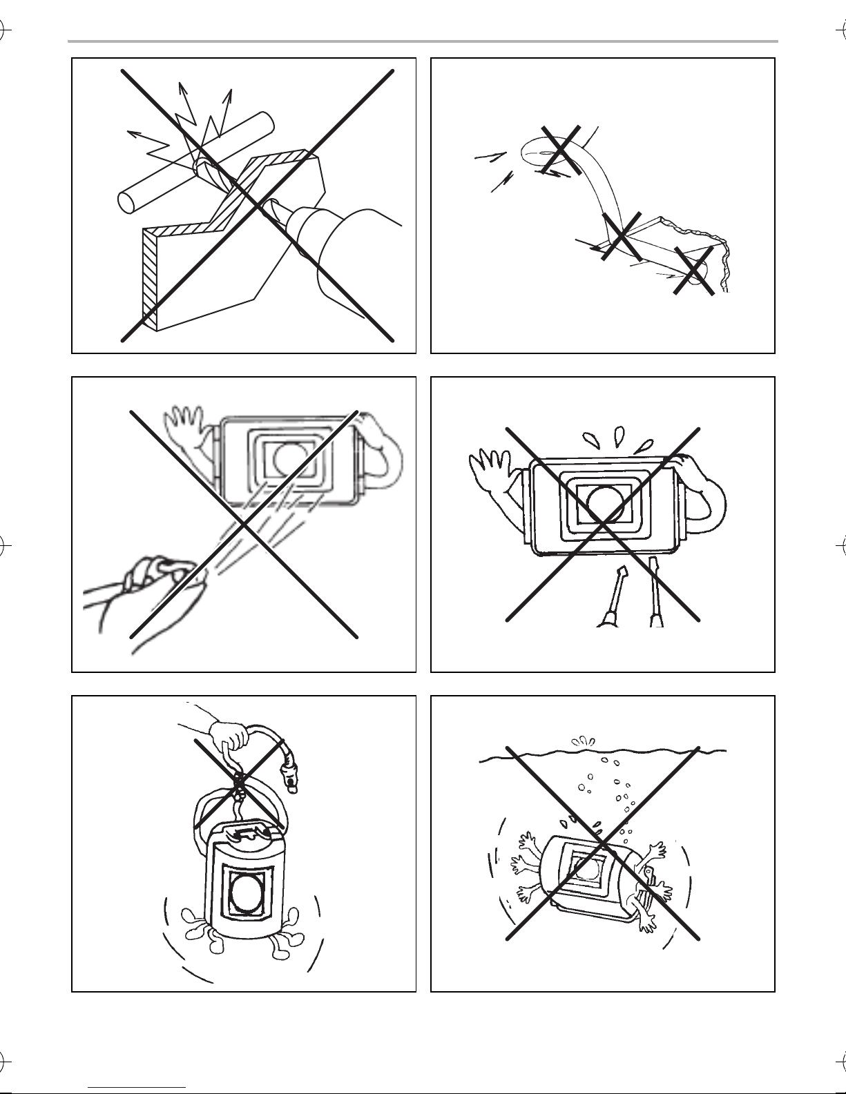
The camera is watertight. However, the sealings on the camera cannot withstand a high-pressure
cleaner (fig. 4, page 4). Therefore, you should observe the following instructions when handling
the camera:
• Do not open the camera, as this impairs the sealing and the function of the camera (fig. 5,
page 4).
• Do not pull at the cables, as this impairs the sealing and the function of the camera (fig. 6,
page 4).
• The camera is not suitable for submerged operation (fig. 7, page 4).
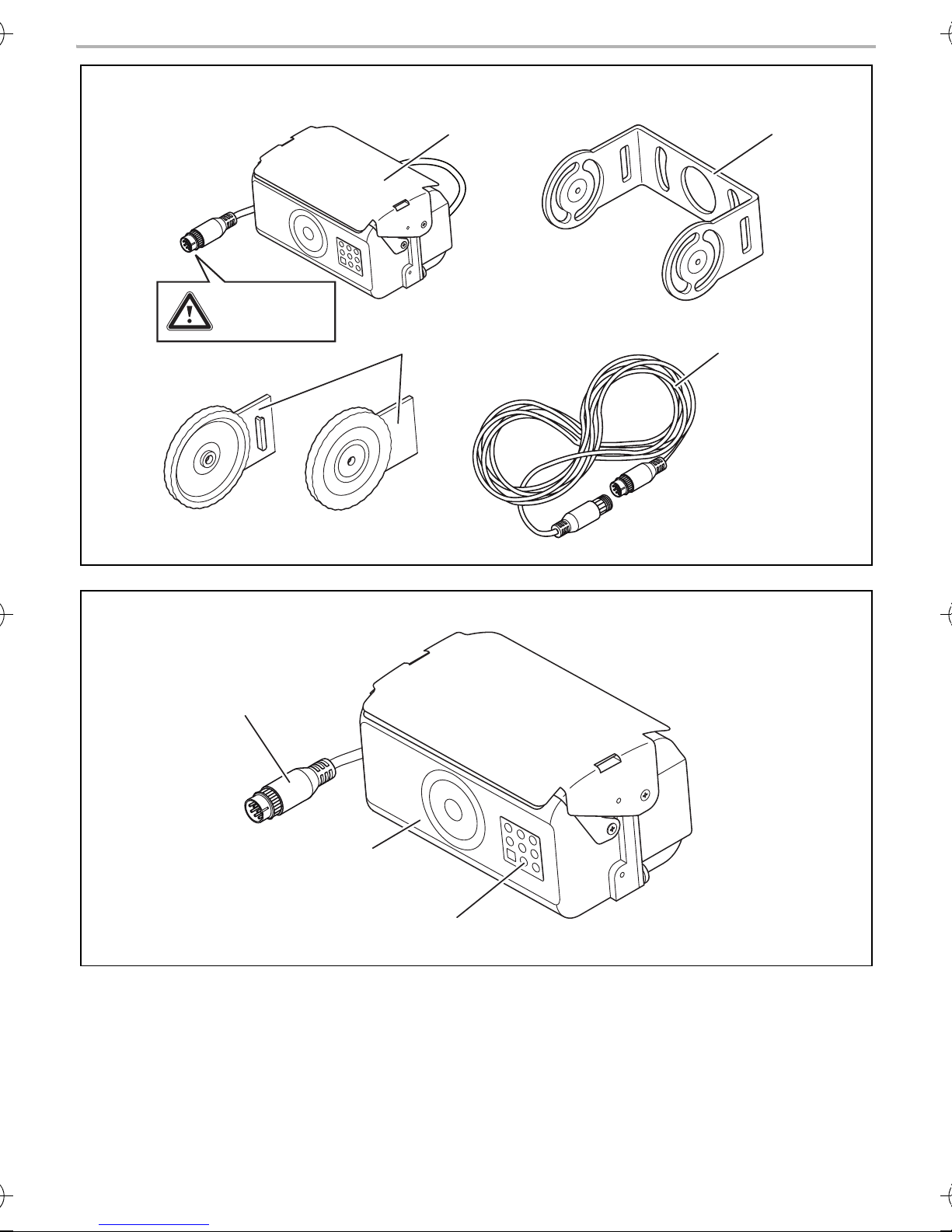
3Scope of delivery
No. in
fig. 8,
page 5
1 1 Colour camera CAM80CM 9600000049 (PAL)/
Quantity Description Ref. no.
9600000198 (NTSC)
2 1 Camera bracket 9102200073
32Side covers
4 1 Extension cable 9102200030
–1Fastening material
4 Accessories
Available as accessory (not included in scope of delivery):
Description Ref. no.
Extension cable 5 m 91022000028
Extension cable 8 m 91022000029
Extension cable 20 m 91022000030
Spiral cable for trailer operation 91022000031
12
Page 13

CAM80CM Intended use
EN
5Intended use
The CAM80CM colour camera is designed primarily for use in vehicles. It can be used in video
systems to observe the space around the vehicle from the driver's seat when manoeuvring or
parking, for example.
WARNING!
!
Risk of injury!
Since rear view systems are designed merely as an additional aid for reversing, it does
not relieve you of the duty to take proper care when reversing.
6 Technical description
The camera, which is encased in aluminium housing, transmits image and sound to a monitor via a
cable. The built-in infrared LEDs improve night vision.
The camera transmits the image as if you are looking in the rear mirror.
The camera consists of the following main elements:
No. in
fig. 9, page 5
1 6-pin connection cable
2Microphone
3 Infrared LEDs
Description
13
Page 14

Information on the electrical connections CAM80CM
EN
7 Information on the electrical connections
7.1 Layi ng cables
NOTICE! Risk of damage!
A
Please observe the following instructions:
• As far as possible, use original openings or alternative openings for the connecting cable duct,
e.g. the paneling edges, ventilation grilles or blank panels. If no openings are available, you
must drill holes for the cables. Check beforehand that there is sufficient room for the drill head
to come out on the other side.
• To prevent damage, when drilling ensure that there is sufficient space on the other
side for the drill head to come out.
• Cables and connections which are not properly installed will cause malfunctions or
damage to components. Correct installation of cables and connections is the basic
prerequisite for lasting and trouble-free operation of the retrofitted components.
• The cables may not be exposed for long periods to solvents such as benzine, as the
solvents can damage the cable.
• Wherever possible lay cables inside the vehicle, as they are better protected inside than outside
the vehicle.
If you do need to lay a cable outside the vehicle, ensure that it is well secured (use additional
cable ties, insulating tape, etc.).
• To prevent damage to the cables, when laying them ensure that there is sufficient distance to
hot or moving vehicle components (exhaust pipes, drive shafts, light systems, fans, heater etc.).
Use corrugated piping or other protective materials to protect against mechanical wear.
• Screw on the plug connection of the connecting cables to protect against water penetration
(fig. g, page 7).
• When laying electric connections, ensure that
– They are not kinked or twisted
– They do not rub on edges
– They are not laid in sharp edged ducts without protection (fig. 3, page 4)
• Attach the cables securely in the vehicles to prevent tripping hazards. Use cable binders,
insulating tape or glue the cables in place.
• Protect every through-hole made in the bodywork against water penetration, e.g. by using a
cable with a sealant and by spraying the cable and the the cable sleeve with sealant.
NOTE
I
Do not start sealing the through-holes until all installation work has been finished for the
camera, and the required cable lengths have been established.
14
Page 15

CAM80CM Mounting the camera
EN
8 Mounting the camera
8.1 Tools required
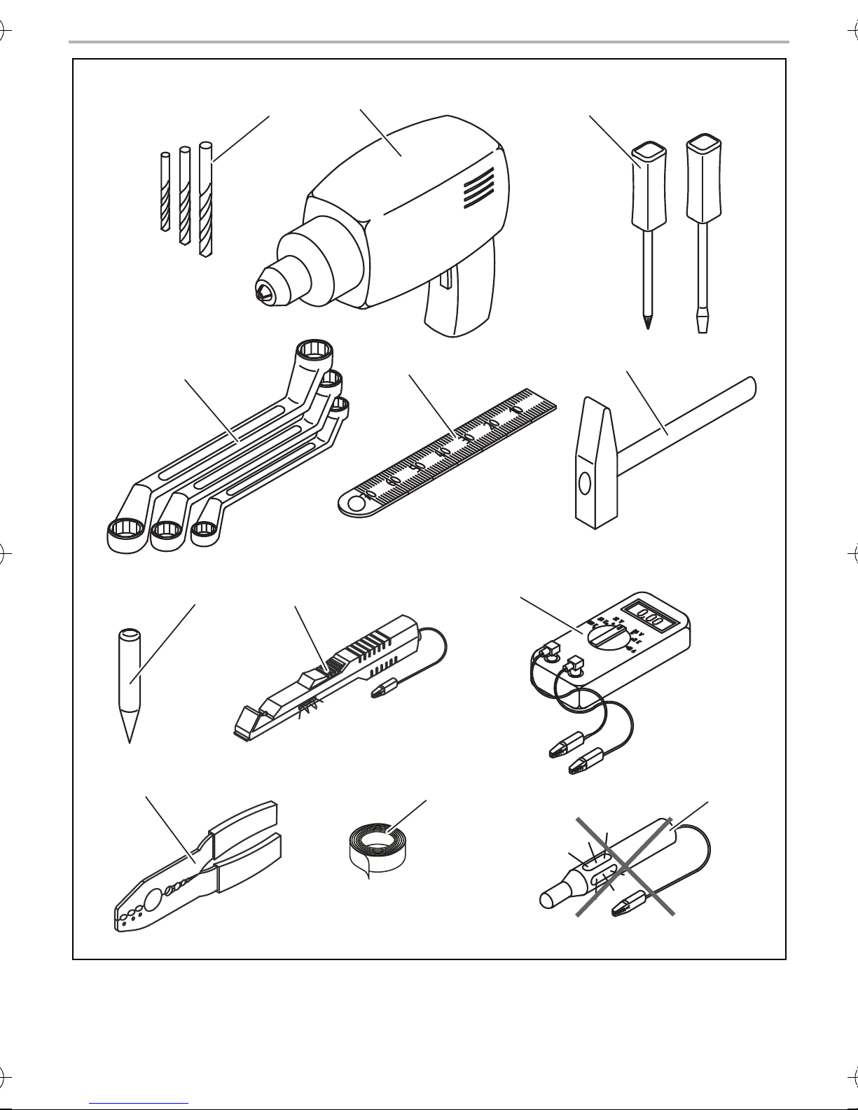
For installation and assembly you will require the following tools:
• Drill bit set (fig. 1 1, page 3)
• Drill (fig. 1 2, page 3)
• Screwdriver (fig. 1 3, page 3)
• Set of ring or open-ended spanners (fig. 1 4, page 3)
• Measuring ruler (fig. 1 5, page 3)
• Hammer (fig. 1 6, page 3)
• Centre punch (fig. 1 7, page 3)
To make and test the electrical connection, the following tools are required:
• Diode test lamp (fig. 1 8, page 3) or voltmeter (fig. 1 9, page 3)
• Crimping tool (fig. 1 10, page 3)
• Insulating tape (fig. 1 11, page 3)
• Cable bushing sleeves, if necessary
To fasten the cables you may require additional cable binders.
8.2 Mounting the camera
CAUTION!
!
I
Select a location for the camera and attach it so securely that it cannot under any
circumstances fall off and injure bystanders (e.g. by being knocked off by branches
brushing over the roof of the vehicle).
NOTE
If installing the camera alters the vehicle height or length specified in the vehicle
documents, your vehicle must be inspected by the appropriate authorities.
Make sure that you are in possession of documents verifying that your vehicle has
passed this inspection.
Observe the following installation instructions:
• To provide a suitable viewing angle, the camera must be attached at a height of at least 2 m.
Ensure that you have a firm place from which to work when mounting the camera.
• Ensure that the installation location of the camera is sufficiently firm (e.g. to prevent the camera
from being knocked down by branches that may brush over the roof of the vehicle).
15
Page 16

Mounting the camera CAM80CM
EN
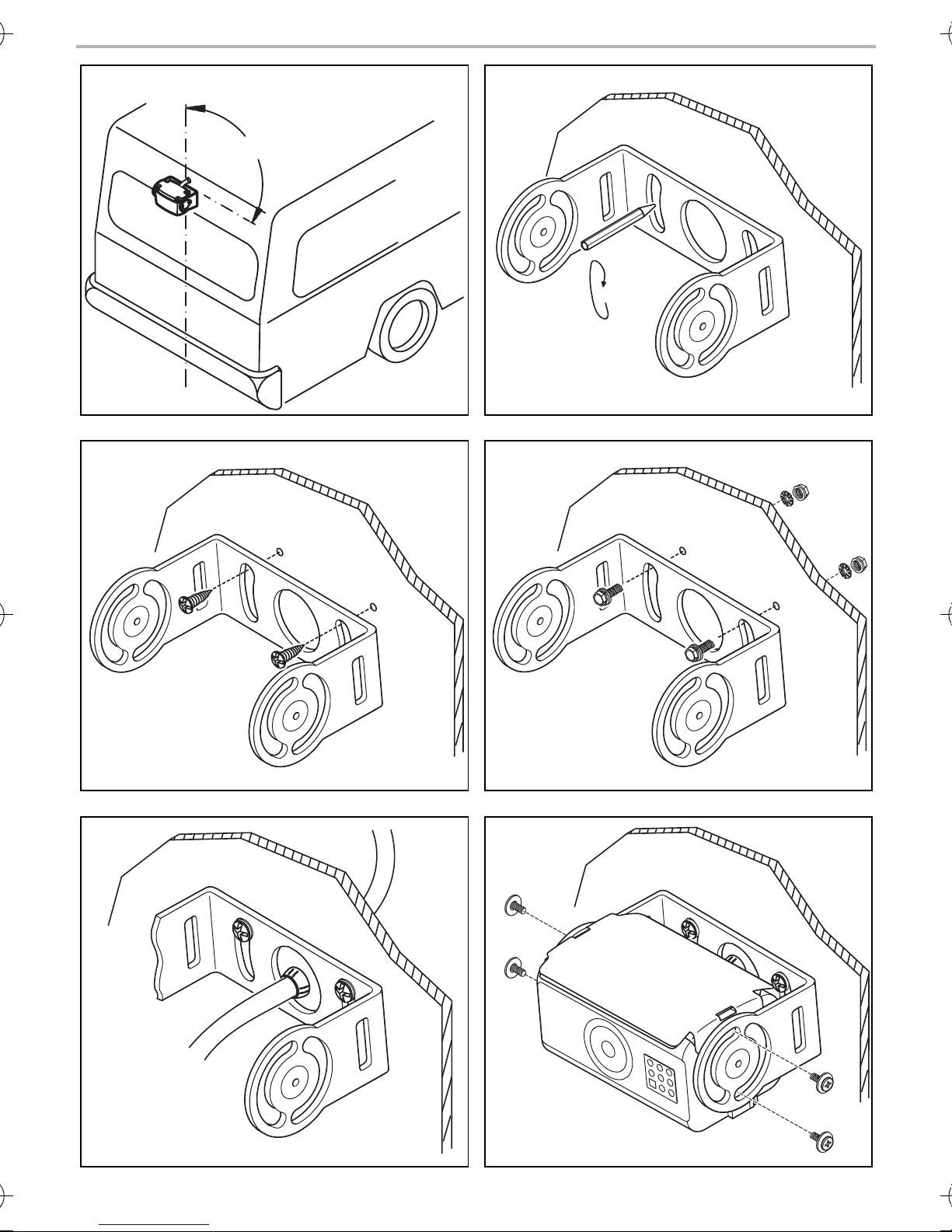
• Mount the camera bracket horizontally and in the middle of the rear of the vehicle (fig. 0,
page 6).
• The most secure type of attachment is with screws fitted through the body. Please observe the
following instructions:
– There must be sufficient space for the mounting procedure behind the chosen installation
location.
– Suitable measures must be taken to prevent water penetrating through any holes made
(e.g. by using screws and sealant and/or spraying the outer attachment parts with a
sealant).
– The location on the body where you wish to attach the camera must be rigid enough to
allow the camera to be tightly fastened.
• Check beforehand that there is sufficient room for the drill head to come out on the other side
(fig. 2, page 4).
• If you are not sure about the location you have chosen, consult the vehicle manufacturer or
dealer.
NOTE
I
We recommend greasing the threads of the bolts to prevent corrosion.
When mounting the camera, proceed as follows:
➤ Hold the camera on the chosen location and mark at least two different points for the drill holes
(fig. a, page 6).
➤ Using a hammer and centre punch, gently pre-punch the previously marked points to prevent
the drill head from slipping off.
If you want to screw on the camera with self-tapping screws (fig. b, page 6)
NOTICE! Risk of damage!
A
➤ Drill Ø 4 mm holes at the points you have just marked.
➤ Deburr all drill holes and apply rust-protection.
➤ Screw the camera bracket on with the 5 x 20 mm self-tapping screws.
The holder may only be attached to steel panels with a minimum thickness of 1.5 mm
using self-tapping screws.
16
Page 17

CAM80CM Mounting the camera
EN
If you would like to attach the camera with threaded screws fitted through the
construction (fig. c, page 6)
NOTICE! Risk of damage!
A
➤ Drill Ø 4.5 mm holes at the points you have just marked.
➤ Deburr all drill holes and apply rust-protection.
➤ Screw the camera bracket on with the M5 x 20 mm threaded screws.
Depending on the thickness of the construction, you may require longer threaded screws.
Creating a through-hole for the camera connection cable (fig. d, page 6)
I
Ensure that that nuts cannot be pulled through the body shell when they are tightened.
Use larger washers or metal plates if necessary.
NOTE
If possible, use available openings – such as ventilation grilles – to feed the connection
cables through. If there are no existing openings, you must drill a hole with a
16 mm diameter.
NOTICE! Risk of damage!
A
➤ Drill a hole of Ø 16 mm near the camera.
➤ Deburr all drill holes that have been made in the sheet metal and apply rust-protection.
➤ Place cable sleeves in all sharp edged ducts.
Mounting the camera
A
➤ Push the camera into the camera bracket.
➤ Attach the camera loosely with the two screws M3 x 8 mm in the slots (fig. e, page 6).
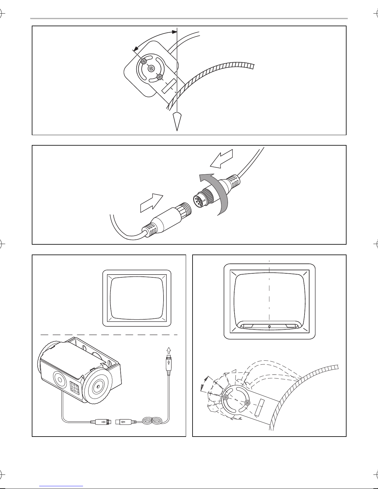
➤ Align the camera provisorily so that the lens is at an angle of approx. 50° to the perpendicular
axis of the vehicle (fig. f, page 7).
A
Ensure that there is sufficient space on the other side for the drill head to come out
NOTICE! Risk of damage!
Only use the screws supplied to mount the camera in the camera bracket. Longer
screws will damage the camera.
NOTICE! Risk of damage!
Never mount the camera without the camera guard.
17
Page 18

Mounting the camera CAM80CM
EN
Connecting the camera
NOTE
I
➤ Guide the camera cable into the vehicle interior.
➤ Insert the plug of the camera cable into the socket of the extension cable.
➤ Screw on the plug connection of the connecting cables to protect against water penetration
(fig. g, page 7).
Aligning the camera
• Lay the camera cable so that should you need to remove the camera, you can access
the plug connection between the camera and the extension cable easily.
This considerably eases dismantling work.
• To minimise corrosion in the plug, apply a small amount of grease – such as pin
grease – inside the plug.
• Additional extension cables are available on request (see chapter “Accessories” on
page 12).
NOTE
I
➤ Use the monitor image to align the camera:
The monitor image should show the bottom edge of the rear or the bumper of your
vehicle (A). The middle of the bumper should be in the middle of the screen (fig. i, page 7).
➤ Check the function of the camera after you have connected it to a monitor.
Fastening the camera
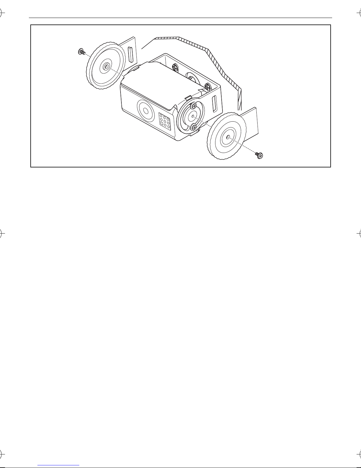
➤ Thighten the two screws in the slots of the camera bracket.
➤ Mount the side covers with the two screws M3 x 8 mm in the middle drill holes (fig. j,
page 8).
If necessary before aligning the camera connect the camera to a monitor and to a
power supply (see connecting diagram, fig. h, page 7
18
Page 19

CAM80CM Cleaning and caring for the camera
EN
9 Cleaning and caring for the camera
NOTICE! Risk of damage!
A
➤ Clean the camera with a soft, damp cloth from time to time.
Do not use sharp or hard objects to clean the device as these may damage the device.
10 Guarantee
The statutory warranty period applies. If the product is defective, please contact the
manufacturer's branch in your country (see the back of the instruction manual for the addresses) or
your retailer.
For repair and guarantee processing, please send the following items:
• Defect components
• A copy of the receipt with purchasing date
• A reason for the claim or description of the fault
11 Disposal
➤ Place the packaging material in the appropriate recycling waste bins wherever possible.
If you wish to finally dispose of the product, ask your local recycling centre or specialist
dealer for details about how to do this in accordance with the applicable disposal regu-
M
lations.
19
Page 20
Technical data CAM80CM
EN
E
12 Technical data
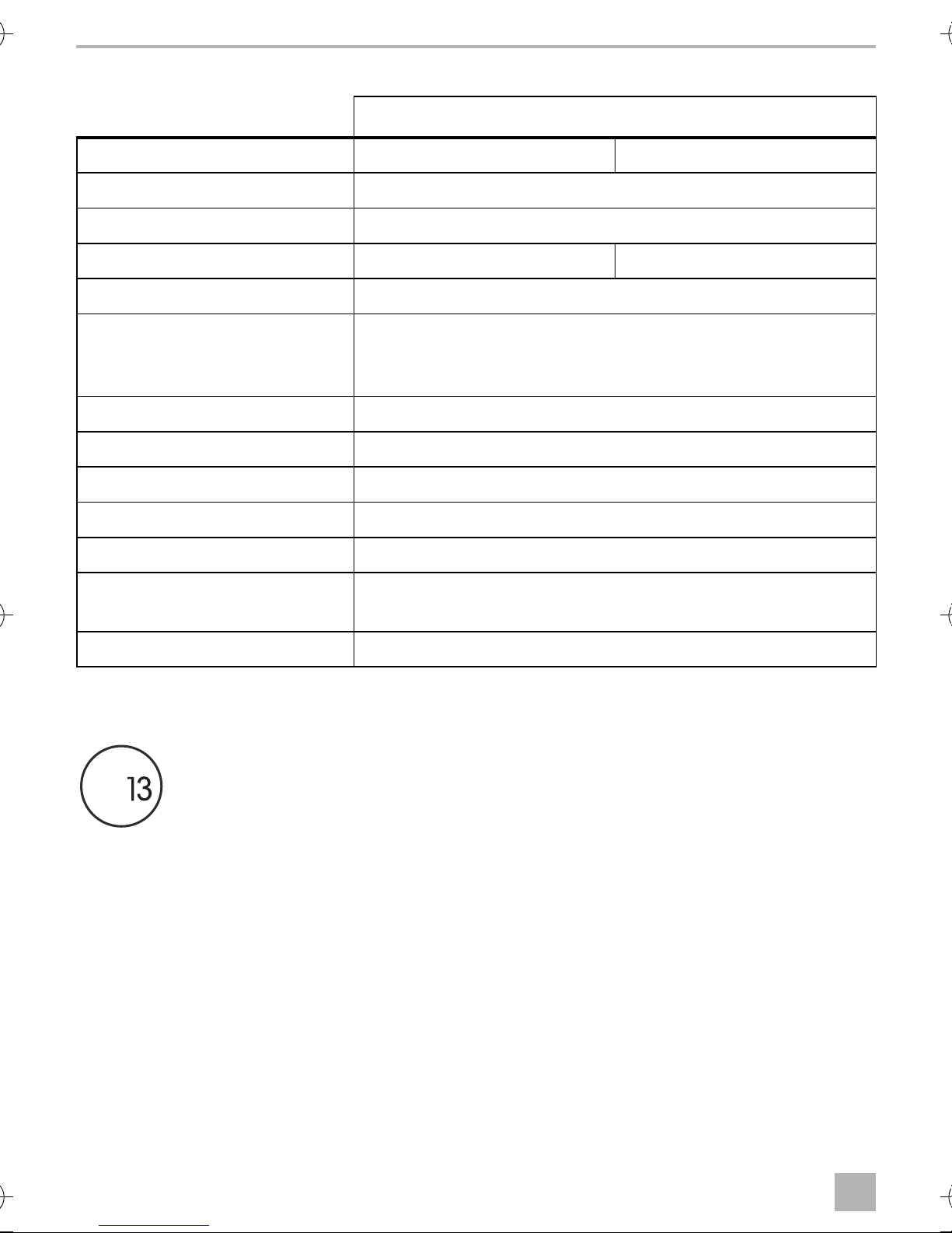
PerfectView CAM80CM
Ref. no: 9600000049 9600000198
Image sensor: 1/3" CCD
Pixels: approx. 270000 pixels
Video standard: PAL, 1 Vpp NTSC, 1 Vpp
Light sensitivity: < 1 Lux
Picture angle: approx. 145° diagonal
approx. 100° horizontal
approx. 72° vertical
Operating voltage: 11 – 16 Vg
Power consumption: 1.8 W
Operating temperature: –20 °C to +65 °C
Protection class: IP68
Resistance against vibration: 6g
Dimensions W x H x D
(with camera bracket):
Weight: approx. 0.35 kg
Approval
The device has the E13 approval.
106 x 68 x 54 mm
20
Page 21

CAM80CM Erklärung der Symbole
DE
Bitte lesen Sie diese Anleitung vor Einbau und Inbetriebnahme sorgfältig durch und
bewahren Sie sie auf. Geben Sie sie im Falle einer Weitergabe des Produktes an den
Nutzer weiter.
Inhaltsverzeichnis
1 Erklärung der Symbole . . . . . . . . . . . . . . . . . . . . . . . . . . . . . . . . . . . . . . . . . . . . . . . . . . . . . . 21
2 Sicherheits- und Einbauhinweise. . . . . . . . . . . . . . . . . . . . . . . . . . . . . . . . . . . . . . . . . . . . . .22
3 Lieferumfang . . . . . . . . . . . . . . . . . . . . . . . . . . . . . . . . . . . . . . . . . . . . . . . . . . . . . . . . . . . . . .24
4 Zubehör . . . . . . . . . . . . . . . . . . . . . . . . . . . . . . . . . . . . . . . . . . . . . . . . . . . . . . . . . . . . . . . . .24
5 Bestimmungsgemäßer Gebrauch . . . . . . . . . . . . . . . . . . . . . . . . . . . . . . . . . . . . . . . . . . . . .25
6 Technische Beschreibung . . . . . . . . . . . . . . . . . . . . . . . . . . . . . . . . . . . . . . . . . . . . . . . . . . .25
7 Hinweise zum elektrischen Anschluss. . . . . . . . . . . . . . . . . . . . . . . . . . . . . . . . . . . . . . . . . .26
8 Kamera montieren . . . . . . . . . . . . . . . . . . . . . . . . . . . . . . . . . . . . . . . . . . . . . . . . . . . . . . . . .27
9 Kamera pflegen und reinigen. . . . . . . . . . . . . . . . . . . . . . . . . . . . . . . . . . . . . . . . . . . . . . . . . 31
10 Gewährleistung . . . . . . . . . . . . . . . . . . . . . . . . . . . . . . . . . . . . . . . . . . . . . . . . . . . . . . . . . . . 31
11 Entsorgung . . . . . . . . . . . . . . . . . . . . . . . . . . . . . . . . . . . . . . . . . . . . . . . . . . . . . . . . . . . . . . . 31
12 Technische Daten . . . . . . . . . . . . . . . . . . . . . . . . . . . . . . . . . . . . . . . . . . . . . . . . . . . . . . . . . .32
1 Erklärung der Symbole
WARNUNG!
!
!
A
Sicherheitshinweis: Nichtbeachtung kann zu Tod oder schwerer Verletzung führen.
VORSICHT!
Sicherheitshinweis: Nichtbeachtung kann zu Verletzungen führen.
ACHTUNG!
Nichtbeachtung kann zu Materialschäden führen und die Funktion des Produktes
beeinträchtigen.
HINWEIS
I
Ergänzende Informationen zur Bedienung des Produktes.
21
Page 22

Sicherheits- und Einbauhinweise CAM80CM
DE
2 Sicherheits- und Einbauhinweise
Der Hersteller übernimmt in folgenden Fällen keine Haftung für Schäden:
• Montage- oder Anschlussfehler
• Beschädigungen am Produkt durch mechanische Einflüsse und Überspannungen
• Veränderungen am Produkt ohne ausdrückliche Genehmigung vom Hersteller
• Verwendung für andere als die in der Anleitung beschriebenen Zwecke
Beachten Sie die vom Fahrzeughersteller und vom Kfz-Handwerk vorgeschriebenen
Sicherheitshinweise und Auflagen!
WARNUNG!
Unzureichende Leitungsverbindungen können zur Folge haben, dass durch Kurzschluss
!
• Kabelbrände entstehen,
• der Airbag ausgelöst wird,
• elektronische Steuerungseinrichtungen beschädigt werden,
• elektrische Funktionen ausfallen (Blinker, Bremslicht, Hupe, Zündung, Licht).
ACHTUNG!
Klemmen Sie wegen der Kurzschlussgefahr vor Arbeiten an der Fahrzeugelektrik immer
A
Beachten Sie deshalb folgende Hinweise:
• Verwenden Sie bei Arbeiten an den folgenden Leitungen nur isolierte Kabelschuhe, Stecker
und Flachsteckhülsen:
– 30 (Eingang von Batterie Plus direkt)
– 15 (Geschaltetes Plus, hinter Batterie)
– 31 (Rückleitung ab Batterie, Masse)
– L (Blinkerleuchten links)
– R (Blinkerleuchten rechts)
Verwenden Sie keine Lüsterklemmen.
• Verwenden Sie eine Krimpzange zum Verbinden der Kabel.
• Schrauben Sie das Kabel bei Anschlüssen an Leitung 31 (Masse)
– mit Kabelschuh und Zahnscheibe an eine fahrzeugeigene Masseschraube oder
– mit Kabelschuh und Blechschraube an das Karosserieblech.
den Minuspol ab.
Bei Fahrzeugen mit Zusatzbatterie müssen Sie an dieser ebenfalls den Minuspol abklemmen.
Achten Sie auf eine gute Masseübertragung!
22
Page 23

CAM80CM Sicherheits- und Einbauhinweise
DE
Beim Abklemmen des Minuspols der Batterie verlieren alle flüchtigen Speicher der Komfortelektronik ihre gespeicherten Daten.
• Folgende Daten müssen Sie je nach Fahrzeugausstattung neu einstellen:
–Radiocode
–Fahrzeuguhr
– Zeitschaltuhr
– Bordcomputer
– Sitzposition
Hinweise zur Einstellung finden Sie in der jeweiligen Bedienungsanleitung.
Beachten Sie folgende Hinweise bei der Montage:
VORSICHT!
!
A
Beachten Sie folgende Hinweise bei der Arbeit an elektrischen Teilen:
A
• Befestigen Sie die im Fahrzeug montierten Teile so, dass sie sich unter keinen
Umständen (scharfes Abbremsen, Verkehrsunfall) lösen und zu Verletzungen der
Fahrzeuginsassen führen können.
• Befestigen Sie verdeckt unter Verkleidungen anzubringende Teile des Systems so,
dass sie sich nicht lösen oder andere Teile und Leitungen beschädigen und keine
Fahrzeugfunktionen (Lenkung, Pedale usw.) beeinträchtigen können.
• Beachten Sie immer die Sicherheitshinweise des Fahrzeugherstellers.
Einige Arbeiten (z. B. an Rückhaltesystemen wie Airbag usw.) dürfen nur von geschultem Fachpersonal durchgeführt werden.
ACHTUNG!
• Achten Sie beim Bohren auf ausreichenden Freiraum für den Bohreraustritt, um Schäden zu vermeiden.
• Entgraten Sie jede Bohrung und behandeln Sie diese mit Rostschutzmittel.
ACHTUNG!
• Benutzen Sie zum Prüfen der Spannung in elektrischen Leitungen nur eine Diodenprüflampe oder ein Voltmeter.
Prüflampen mit einem Leuchtkörper nehmen zu hohe Ströme auf, wodurch die Fahrzeugelektronik beschädigt werden kann.
• Beachten Sie beim Verlegen der elektrischen Anschlüsse, dass diese
– nicht geknickt oder verdreht werden,
– nicht an Kanten scheuern,
– nicht ohne Schutz durch scharfkantige Durchführungen verlegt werden.
• Isolieren Sie alle Verbindungen und Anschlüsse.
• Sichern Sie die Kabel gegen mechanische Beanspruchung durch Kabelbinder oder
Isolierband, z. B. an vorhandenen Leitungen.
23
Page 24

Lieferumfang CAM80CM
DE
Die Kamera ist wasserdicht. Die Dichtungen der Kamera halten aber nicht einem Hochdruckreiniger stand (Abb. 4, Seite 4). Beachten Sie deshalb folgende Hinweise zum Umgang mit der
Kamera:
• Öffnen Sie die Kamera nicht, da dieses ihre Dichtigkeit und die Funktionsfähigkeit beeinträchtigt (Abb. 5, Seite 4).
• Ziehen Sie nicht an den Kabeln, da dieses die Dichtigkeit und die Funktionsfähigkeit der
Kamera beeinträchtigt (Abb. 6, Seite 4).
• Die Kamera ist nicht für den Betrieb unter Wasser geeignet (Abb. 7, Seite 4).
3Lieferumfang
Nr. in
Abb. 8,
Seite 5
1 1 Farbkamera CAM80CM 9600000049 (PAL)/
Menge Bezeichnung Artikel-Nr.
9600000198 (NTSC)
2 1 Kamerahalter 9102200073
3 2 Seitenabdeckungen
4 1 Verlängerungskabel 9102200030
–1Befestigungsmaterial
4Zubehör
Als Zubehör erhältlich (nicht im Lieferumfang enthalten):
Bezeichnung Artikel-Nr.
Verlängerungskabel 5 m 91022000028
Verlängerungskabel 8 m 91022000029
Verlängerungskabel 20 m 91022000030
Spiralkabel für Anhängerbetrieb 91022000031
24
Page 25

CAM80CM Bestimmungsgemäßer Gebrauch
DE
5 Bestimmungsgemäßer Gebrauch
Die Farbkamera CAM80CM ist vorrangig für den Einsatz in Fahrzeugen gedacht. Sie ist einsetzbar
in Videosystemen, die zur Beobachtung des Bereiches um das Fahrzeug vom Fahrersitz aus
dienen, z. B. beim Rangieren oder Einparken.
WARNUNG!
!
Gefahr von Personenschäden durch das Fahrzeug.
Rückfahrvideosysteme stellen eine Unterstützung beim Rückwärtsfahren dar,
sie entbinden Sie jedoch nicht von der besonderen Vorsichtspflicht beim
Rückwärtsfahren.
6 Technische Beschreibung
Die Kamera ist in einem Aluminiumgehäuse untergebracht und überträgt Bild und Ton über ein
Kabel zu einem Monitor. Durch die Infrarot-LEDs wird die Nachtsicht verbessert.
Die Kamera übermittelt das Bild, als ob Sie in den Rückspiegel blicken.
Die Kamera besteht aus u. a. folgenden Elementen:
Nr. in
Abb. 9, Seite 5
1 6-poliges Anschlusskabel
2Mikrofon
3Infrarot-LEDs
Bezeichnung
25
Page 26

Hinweise zum elektrischen Anschluss CAM80CM
DE
7 Hinweise zum elektrischen Anschluss
7.1 Kabel verlegen
ACHTUNG! Beschädigungsgefahr!
A
Beachten Sie deshalb folgende Hinweise:
• Verwenden Sie für die Durchführung der Anschlusskabel nach Möglichkeit Originaldurchführungen oder andere Durchführungsmöglichkeiten, z. B. Verkleidungskanten, Lüftungsgitter
oder Blindschalter. Wenn keine Durchführungen vorhanden sind, müssen Sie für die jeweiligen
Kabel entsprechende Löcher bohren. Schauen Sie vorher nach, ob ausreichender Freiraum für
den Bohreraustritt vorhanden ist.
• Wenn Sie Löcher bohren, prüfen Sie vorher, ob ausreichender Freiraum für den
Bohreraustritt vorhanden ist.
• Nicht fachgerechte Kabelverlegungen und Kabelverbindungen führen immer
wieder zu Fehlfunktionen oder Beschädigungen von Bauteilen. Eine korrekte
Kabelverlegung bzw. Kabelverbindung ist die Grundvoraussetzung für eine
dauerhafte und fehlerfreie Funktion der nachgerüsteten Komponenten.
• Die Kabel dürfen nicht über längere Zeit mit Lösungsmitteln wie z. B. Benzin in
Berührung kommen, da Lösungsmittel die Kabel beschädigen würden.
• Verlegen Sie die Kabel nach Möglichkeit immer im Fahrzeuginneren, denn dort sind sie besser
geschützt als außen am Fahrzeug.
Wenn Sie die Kabel trotzdem außerhalb des Fahrzeuges verlegen, achten Sie auf eine sichere
Befestigung (durch zusätzliche Kabelbinder, Isolierband usw.).
• Um Beschädigungen am Kabel zu vermeiden, halten Sie beim Verlegen der Kabel immer
ausreichend Abstand zu heißen und sich bewegenden Fahrzeugteilen (Auspuffrohre,
Antriebswellen, Lichtmaschine, Lüfter, Heizung usw.). Verwenden Sie zum mechanischen
Schutz Wellrohr oder ähnliche Schutzmaterialien.
• Verschrauben Sie die Steckverbindungen der Verbindungskabel zum Schutz gegen das
Eindringen von Wasser (Abb. g, Seite 7).
• Beachten Sie beim Verlegen der Kabel, dass diese
– nicht stark geknickt oder verdreht werden,
–nicht an Kanten scheuern,
– nicht ohne Schutz durch scharfkantige Durchführungen verlegt werden (Abb. 3, Seite 4).
• Befestigen Sie die Kabel sicher im Fahrzeug, um ein Verfangen (Sturzgefahr) zu vermeiden.
Dieses kann erfolgen durch den Einsatz von Kabelbindern, Isolierband oder durch Ankleben
mit Klebstoff.
• Schützen Sie jeden Durchbruch an der Außenhaut durch geeignete Maßnahmen gegen
Wassereinbruch, z. B. durch Einsetzen des Kabels mit Dichtungsmasse und durch Abspritzen
des Kabels und der Durchführungstülle mit Dichtungsmasse.
26
Page 27

CAM80CM Kamera montieren
DE
HINWEIS
I
Beginnen Sie mit dem Abdichten der Durchbrüche erst, nachdem alle Einstellarbeiten
an der Kamera abgeschlossen sind und die benötigten Längen der Anschlusskabel
festliegen.
8 Kamera montieren
8.1 Benötigtes Werkzeug
Für Einbau und Montage benötigen Sie folgende Werkzeuge:
• Satz Bohrer (Abb. 1 1, Seite 3)
• Bohrmaschine (Abb. 1 2, Seite 3)
• Schraubendreher (Abb. 1 3, Seite 3)
• Satz Ring- oder Maulschlüssel (Abb. 1 4, Seite 3)
• Maßstab (Abb. 1 5, Seite 3)
• Hammer (Abb. 1 6, Seite 3)
• Körner (Abb. 1 7, Seite 3)
Für den elektrischen Anschluss und seine Überprüfung benötigen Sie folgende Hilfsmittel:
• Diodenprüflampe (Abb. 1 8, Seite 3) oder Voltmeter (Abb. 1 9, Seite 3)
• Krimpzange (Abb. 1 10, Seite 3)
• Isolierband (Abb. 1 11, Seite 3)
• Ggf. Kabeldurchführungstüllen
Zur Befestigung der Kabel benötigen Sie ggf. noch weitere Kabelbinder.
27
Page 28

Kamera montieren CAM80CM
DE
8.2 Kamera montieren
VORSICHT!
!
I
Beachten Sie folgende Hinweise bei der Montage:
• Bringen Sie die Kamera für einen vernünftigen Blickwinkel in mindestens zwei Metern Höhe an.
Achten Sie bei der Montage auf einen ausreichend standfesten Arbeitsplatz.
Wählen Sie den Platz der Kamera so und befestigen Sie diese so sicher, dass unter
keinen Umständen in der Nähe stehende Personen verletzt werden können, z. B. weil
über das Fahrzeugdach streifende Äste die Kamera abreißen.
HINWEIS
Wenn durch den Anbau der Kamera die in den Fahrzeugpapieren eingetragene
Fahrzeughöhe oder Fahrzeuglänge verändert wird, muss eine neue Abnahme durch
die zuständigen Stellen (TÜV, DEKRA usw.) erfolgen.
Lassen Sie die neue Abnahme durch Ihr zuständiges Straßenverkehrsamt in die
Fahrzeugpapiere eintragen.
• Achten Sie darauf, dass der Montageort der Kamera ausreichende Festigkeit bietet
(z.B.können sich über das Fahrzeugdach streifende Äste in der Kamera verfangen).
• Montieren Sie den Kamerahalter waagerecht und mittig am Heck des Fahrzeuges (Abb. 0,
Seite 6).
• Die sicherste Art der Befestigung sind Schrauben, die durch den Aufbau gehen. Beachten Sie
dabei folgende Hinweise:
– Hinter der gewählten Montageposition muss ausreichend Freiraum für die Montage
vorhanden sein.
– Jeder Durchbruch muss durch geeignete Maßnahmen gegen Wassereinbruch geschützt
werden (z. B. durch Einsetzen der Schrauben mit Dichtungsmasse und/oder Abspritzen
der äußeren Befestigungsteile mit Dichtungsmasse).
– Der Aufbau an der Befestigungsstelle muss genügend Festigkeit bieten, damit sich der
Kamerahalter genügend fest anziehen lässt.
• Kontrollieren Sie vorher, ob ausreichender Freiraum für den Bohreraustritt vorhanden ist
(Abb. 2, Seite 4).
• Wenn Sie sich nicht sicher über den von Ihnen gewählten Montageort sind, erkundigen Sie sich
beim Aufbauhersteller oder dessen Vertretung.
HINWEIS
I
Gehen Sie bei der Montage wie folgt vor:
➤ Halten Sie den Kamerahalter an den gewählten Montageort und markieren Sie mindestens
zwei verschiedene Bohrpunkte (Abb. a, Seite 6).
➤ Körnen Sie an den zuvor angezeichneten Punkten mit Hammer und Körner vor, um ein
Verlaufen des Bohrers zu verhindern.
28
Um die Korrosion der Schrauben zu minimieren, fetten Sie die Gewinde ein.
Page 29

CAM80CM Kamera montieren
DE
Wenn Sie die Kamera mit Blechschrauben anschrauben möchten (Abb. b, Seite 6)
ACHTUNG! Beschädigungsgefahr!
A
➤ Bohren Sie an den zuvor angezeichneten Punkten jeweils ein Loch von Ø 4 mm.
➤ Entgraten Sie alle Bohrlöcher und versehen Sie sie mit Rostschutz.
➤ Schrauben Sie den Kamerahalter mit den Blechschrauben 5 x 20 mm an.
Wenn Sie die Kamera mit Gewindeschrauben durch den Aufbau befestigen möchten
(Abb. c, Seite 6)
A
Die Befestigung mit Blechschrauben darf nur in Stahlblechen mit einer Mindestdicke
von 1,5 mm erfolgen.
ACHTUNG! Beschädigungsgefahr!
Achten Sie darauf, dass sich die Muttern beim Anziehen nicht durch den Aufbau
ziehen können.
Verwenden Sie ggf. größere Unterlegscheiben oder Blechplatten.
➤ Bohren Sie an den zuvor angezeichneten Punkten jeweils ein Loch von Ø 4,5 mm.
➤ Entgraten Sie alle Bohrlöcher und versehen Sie sie mit Rostschutz.
➤ Schrauben Sie den Kamerahalter mit den Gewindeschrauben M5 x 20 mm an.
Je nach Aufbaustärke benötigen Sie längere Gewindeschrauben.
Durchbruch für das Anschlusskabel der Kamera anfertigen (Abb. d, Seite 6)
HINWEIS
I
A
➤ Bohren Sie in der Nähe der Kamera ein Loch von Ø 16 mm.
➤ Entgraten Sie alle Bohrlöcher, die im Blech gefertigt sind, und versehen Sie sie mit Rostschutz.
Verwenden Sie für die Durchführung der Anschlusskabel nach Möglichkeit
vorhandene Durchführungsmöglichkeiten, z. B. Lüftungsgitter. Wenn keine
Durchführungen vorhanden sind, müssen Sie ein Loch von Ø 16 mm bohren.
ACHTUNG! Beschädigungsgefahr!
Kontrollieren Sie vorher, ob ausreichender Freiraum für den Bohreraustritt vorhanden
ist.
➤ Versehen Sie alle scharfkantigen Durchführungen mit einer Durchführungstülle.
29
Page 30

Kamera montieren CAM80CM
DE
Kamera montieren
ACHTUNG! Beschädigungsgefahr!
A
➤ Schieben Sie die Kamera in den Kamerahalter ein.
➤ Befestigen Sie die Kamera lose mit den zwei Schrauben M3 x 8 mm in den Langlöchern
(Abb. e, Seite 6).
➤ Richten Sie die Kamera provisorisch so aus, dass das Objektiv einen Winkel von ca. 50° zur
senkrechten Achse des Fahrzeugs bildet (Abb. f, Seite 7).
A
Kamera elektrisch anschließen
I
Verwenden Sie zur Montage der Kamera nur die mitgelieferten Schrauben. Längere
Schrauben beschädigen die Kamera.
ACHTUNG! Beschädigungsgefahr!
Montieren Sie die Kamera nie ohne den Kameraschutz.
HINWEIS
• Verlegen Sie das Kamerakabel so, dass Sie bei einem eventuell notwendigen
Ausbau der Kamera leicht an die Steckerverbindung zwischen Kamera und
Verlängerungskabel kommen. Die Demontage wird dadurch erheblich vereinfacht.
• Um Korrosion im Stecker zu minimieren, geben Sie etwas Fett, z. B. Polfett, in einen
der Stecker.
• Bei Bedarf sind weitere Verlängerungskabel erhältlich (siehe Kapitel „Zubehör“ auf
Seite 24).
➤ Führen Sie das Kamerakabel ins Fahrzeuginnere.
➤ Stecken Sie den Stecker des Kamerakabels in die Steckbuchse des Verlängerungskabels.
➤ Verschrauben Sie die Steckverbindung zum Schutz gegen das Eindringen von Wasser
(Abb. g, Seite 7).
Kamera ausrichten
HINWEIS
I
➤ Richten Sie die Kamera anhand des Monitorbildes aus:
Das Monitorbild sollte am unteren Bildrand das Heck bzw. die Stoßstange Ihres Fahrzeuges
zeigen. Die Mitte der Stoßstange sollte auch in der Mitte des Monitorbildes sein (Abb. i,
Seite 7).
➤ Prüfen Sie die Funktion der Kamera, nachdem Sie sie an einen Monitor angeschlossen haben.
Zum Ausrichten der Kamera müssen Sie ggf. erst noch einen Monitor montieren und
elektrisch anschließen (siehe Prinzip-Anschlussplan Abb. h, Seite 7).
30
Page 31

CAM80CM Kamera pflegen und reinigen
DE
Kamera befestigen
➤ Ziehen Sie die beiden Befestigungsschrauben in den Langlöchern des Kamerahalters fest.
➤ Befestigen Sie die Seitenabdeckungen mit den beiden Schrauben M3 x 8 mm in den mittleren
Gewindebohrungen (Abb. j, Seite 8).
9 Kamera pflegen und reinigen
ACHTUNG! Beschädigungsgefahr!
A
➤ Reinigen Sie die Kamera gelegentlich mit einem weichen, feuchten Tuch.
Keine scharfen oder harten Mittel zur Reinigung verwenden, da dies zu einer
Beschädigung des Geräts führen kann.
10 Gewährleistung
Es gilt die gesetzliche Gewährleistungsfrist. Sollte das Produkt defekt sein, wenden Sie sich bitte
an die Niederlassung des Herstellers in Ihrem Land (Adressen siehe Rückseite der Anleitung) oder
an Ihren Fachhändler.
Zur Reparatur- bzw. Gewährleistungsbearbeitung müssen Sie Folgendes einschicken:
• defekte Komponenten,
• eine Kopie der Rechnung mit Kaufdatum,
• einen Reklamationsgrund oder eine Fehlerbeschreibung.
11 Entsorgung
➤ Geben Sie das Verpackungsmaterial möglichst in den entsprechenden Recycling-Müll.
Wenn Sie das Produkt endgültig außer Betrieb nehmen, informieren Sie sich bitte beim
nächsten Recyclingcenter oder bei Ihrem Fachhändler über die zutreffenden
M
Entsorgungsvorschriften.
31
Page 32

Technische Daten CAM80CM
DE
E
12 Technische Daten
PerfectView CAM80CM
Art.-Nr.: 9600000049 9600000198
Bildsensor: 1/3" CCD
Bildpunkte: ca. 270000 Pixel
Videostandard: PAL, 1 Vpp NTSC, 1 Vpp
Empfindlichkeit: < 1 Lux
Blickwinkel: ca. 145° diagonal
ca. 100° horizontal
ca. 72° vertikal
Betriebsspannung: 11 – 16 Vg
Verbrauch: 1,8 W
Betriebstemperatur: –20 °C bis +65 °C
Schutzklasse: IP68
Vibrationsfestigkeit: 6g
Abmessungen B x H x T
(mit Halter):
Gewicht: ca. 0,35 kg
Zulassungen
Das Gerät hat die E13-Zulassung.
106 x 68 x 54 mm
32
Page 33

CAM80CM
FR
Veuillez lire attentivement cette notice avant le montage et la mise en service. Veuillez
ensuite la conserver. En cas de passer le produit, veuillez le transmettre au nouvel
acquéreur.
Table des matières
1 Explication des symboles. . . . . . . . . . . . . . . . . . . . . . . . . . . . . . . . . . . . . . . . . . . . . . . . . . . .34
2 Consignes de sécurité et instructions de montage. . . . . . . . . . . . . . . . . . . . . . . . . . . . . . . .34
3 Pièces fournies . . . . . . . . . . . . . . . . . . . . . . . . . . . . . . . . . . . . . . . . . . . . . . . . . . . . . . . . . . . .36
4 Accessoires . . . . . . . . . . . . . . . . . . . . . . . . . . . . . . . . . . . . . . . . . . . . . . . . . . . . . . . . . . . . . . .37
5 Usage conforme . . . . . . . . . . . . . . . . . . . . . . . . . . . . . . . . . . . . . . . . . . . . . . . . . . . . . . . . . . .37
6 Description technique . . . . . . . . . . . . . . . . . . . . . . . . . . . . . . . . . . . . . . . . . . . . . . . . . . . . . .37
7 Remarques concernant le raccordement électrique. . . . . . . . . . . . . . . . . . . . . . . . . . . . . . .38
8 Montage de la caméra . . . . . . . . . . . . . . . . . . . . . . . . . . . . . . . . . . . . . . . . . . . . . . . . . . . . . .39
9 Entretien et nettoyage de la caméra . . . . . . . . . . . . . . . . . . . . . . . . . . . . . . . . . . . . . . . . . . .43
10 Garantie. . . . . . . . . . . . . . . . . . . . . . . . . . . . . . . . . . . . . . . . . . . . . . . . . . . . . . . . . . . . . . . . . .43
11 Retraitement . . . . . . . . . . . . . . . . . . . . . . . . . . . . . . . . . . . . . . . . . . . . . . . . . . . . . . . . . . . . . .43
12 Caractéristiques techniques. . . . . . . . . . . . . . . . . . . . . . . . . . . . . . . . . . . . . . . . . . . . . . . . . .44
33
Page 34

Explication des symboles CAM80CM
FR
1 Explication des symboles
AVERTISSEMENT !
!
!
A
I
Consigne de sécurité : le non-respect de ces consignes peut entraîner la mort ou de
graves blessures.
ATTENTION !
Consigne de sécurité : le non-respect de ces consignes peut entraîner des bles-
sures.
AVIS !
Le non-respect de ces consignes peut entraîner des dommages matériels et des dysfonctionnements du produit.
REMARQUE
Informations complémentaires sur l'utilisation du produit.
2 Consignes de sécurité et instructions de montage
Le fabricant décline toute responsabilité pour des dommages dans les cas suivants :
• des défauts de montage ou de raccordement
• des influences mécaniques et des surtensions ayant endommagé le matériel
• des modifications apportées au produit sans autorisation explicite de la part du fabricant
• une utilisation différente de celle décrite dans la notice
Respectez les consignes de sécurité et autres prescriptions imposées par le fabricant
du véhicule et par les professionnels de l'automobile !
AVERTISSEMENT !
Tout branchement électrique inadéquat peut entraîner un court-circuit causant
!
• la combustion de câbles,
• le déclenchement de l'airbag,
• l’endommagement des dispositifs électroniques de commande,
• la défaillance des fonctions électriques (clignotants, feux-stop, klaxon, allumage,
éclairage).
AVIS !
Débranchez toujours la borne négative avant de procéder à des travaux sur les éléments
A
34
électriques du véhicule afin d’éviter tout risque de court-circuit.
Sur les véhicules équipés d’une batterie supplémentaire, vous devez également
débrancher le pôle négatif de cette dernière.
Page 35

CAM80CM Consignes de sécurité et instructions de montage
FR
Veuillez donc respecter les consignes suivantes :
• Pour tous les travaux sur les lignes électriques suivantes, n’utilisez que des cosses de câble,
fiches et alvéoles pour contacts plats isolés :
– 30 (entrée directe pôle positif de la batterie)
–15 (pôle positif connecté, derrière la batterie)
– 31 (ligne de retour à partir de la batterie, masse)
– L (clignotants gauches)
– R (clignotants droits)
N’utilisez pas de dominos.
• Utilisez une pince à sertir pour relier les câbles.
• Pour les raccordements à la ligne électrique 31 (masse), vissez le câble
– à une vis de masse du véhicule, avec une cosse et une rondelle crantée, ou bien
– à la carrosserie, avec une cosse et une vis à tôle.
Veillez à une bonne transmission de la masse !
Lorsque vous débranchez le pôle négatif de la batterie, les mémoires volatiles de l’électronique de
confort perdent toutes les données enregistrées.
• Vous devez procéder à un nouveau réglage des données suivantes en fonction de l’équipement du véhicule :
–code radio
– horloge du véhicule
–minuterie
– ordinateur de bord
– position du siège
Les instructions de réglage figurent dans les notices d’utilisation correspondantes.
Veuillez respecter les consignes suivantes lors du montage :
ATTENTION !
!
• Fixez les pièces installées dans le véhicule de manière à ce qu’elles ne puissent en
aucun cas se desserrer (freinage abrupt, accident) et risquer de causer des blessures
aux occupants du véhicule.
• Fixez les pièces du système sous l'habillage de telle sorte qu'elles ne puissent pas se
détacher, endommager d'autres pièces ou connexions, ni gêner le fonctionnement
du véhicule (direction, pédales, etc.).
• Respectez toujours les consignes de sécurité du fabricant du véhicule.
Certains travaux (p. ex. au niveau des systèmes de retenue, AIRBAG, etc.) doivent
être effectués uniquement par un personnel spécialisé ayant reçu une formation correspondante.
AVIS !
A
• Avant de percer des trous, assurez-vous que vous disposez d’un espace suffisant de
l'autre côté du trou à percer afin que la mèche n'occasionne aucun dégât.
• Ebavurez tous les trous et protégez-les avec un enduit anticorrosif.
35
Page 36

Pièces fournies CAM80CM
FR
Veuillez respecter les consignes suivantes pour les travaux sur les éléments électriques :
AVIS !
A
La caméra est étanche. Les joints de la caméra ne résistent cependant pas à un nettoyeur à haute
pression (fig. 4, page 4). Veillez donc à respecter les consignes suivantes en manipulant la
caméra :
• N’ouvrez jamais la caméra pour ne pas nuire à son étanchéité et à son fonctionnement (fig. 5,
page 4).
• Ne tirez jamais sur les câbles pour ne pas nuire à l’étanchéité et au fonctionnement de la caméra
(fig. 6, page 4).
• Pour le contrôle de la tension des lignes électriques, n’utilisez qu’une lampe étalon à
diode ou un voltmètre.
Les lampes étalons à corps lumineux absorbent des courants trop élevés qui pourraient endommager les composants électroniques du véhicule.
• Lors de l'installation des raccordements électriques, veillez à ce que ceux-ci
– ne soient ni pliés, ni tordus,
– ne frottent pas contre des arêtes,
– ne soient pas placés dans des passages à arêtes vives sans protection.
• Isolez toutes les connexions et tous les raccords.
• Protégez les câbles contre toute contrainte mécanique en les fixant par exemple aux
lignes existantes à l'aide de serre-câbles ou de ruban vinyle.
• La caméra n’est pas conçue pour une utilisation sous-marine (fig. 7, page 4) !
3Pièces fournies
N° dans
fig. 8,
page 5
1 1 Caméra couleur CAM80CM 9600000049 (PAL)/
2 1 Support de caméra 9102200073
3 2 Couvercle latéral
4 1 Câble de rallonge 9102200030
– 1 Matériel de fixation
Quantité Désignation N° d’article
9600000198 (NTSC)
36
Page 37

CAM80CM Accessoires
FR
4 Accessoires
Disponible en accessoires (non compris dans la livraison) :
Désignation N° d’article
Câble de rallonge 5 m 91022000028
Câble de rallonge 8 m 91022000029
Câble de rallonge 20 m 91022000030
Câble spiralé pour utilisation de remorque 91022000031
5Usage conforme
La caméra couleur CAM80CM est conçue principalement pour être installée dans des véhicules.
Elle peut être utilisée sur les systèmes vidéo qui permettent d'observer, depuis le siège du conducteur, la zone située autour du véhicule, p. ex. pour manœuvrer ou pour se garer.
AVERTISSEMENT !
!
Risque de dommages corporels causés par le véhicule.
Les systèmes vidéo de recul vous apportent une aide supplémentaire en marche
arrière, mais ces appareils ne vous dégagent pas du devoir de prudence qui vous
incombe lorsque vous conduisez en marche arrière.
6 Description technique
La caméra est logée dans un boîtier en aluminium et transmet image et son à l'écran par
l'intermédiaire d'un câble. Les LED infrarouge améliorent la vue de nuit.
La caméra transmet l'image comme si vous regardiez dans le rétroviseur.
La caméra se compose entre autres des éléments suivants :
N° dans
fig. 9, page 5
1 Câble de raccordement à 6 pôles
2Micro
3LED infrarouge
Désignation
37
Page 38

Remarques concernant le raccordement électrique CAM80CM
FR
7 Remarques concernant le raccordement électrique
7.1 Pose des câbles
AVIS ! Risque d’endommagement !
A
Veillez donc à respecter les consignes suivantes :
• Pour la pose des câbles de raccordement, utilisez si possible des passages existants ou d’autres
possibilités de passage telles que les arêtes de garnitures, grilles d’aération ou interrupteurs
aveugles. Si aucun passage n’est disponible, vous devrez percer des trous pour y faire passer
les câbles. Vérifiez avant le perçage qu’il y a un espace suffisant pour la sortie de la mèche de
l’autre côté du trou.
• Avant de percer des trous, vérifiez qu'il y a un espace suffisant de l'autre côté du
trou pour le passage de la mèche.
• Toute erreur de pose ou de branchement des câbles entraîne presque toujours des
perturbations et des détériorations des composants. Une pose et un branchement
corrects des câbles sont indispensables au fonctionnement durable et fiable des
composants que vous installez.
• Veillez à ce que les câbles ne soient pas en contact avec des solvants tels que
l’essence pour une durée prolongée. Ces solvants endommageraient les câbles.
• Autant que possible, ne posez les câbles qu’à l’intérieur du véhicule. Ils y seront mieux
protégés qu’à l’extérieur.
Si vous deviez malgré tout faire passer les câbles à l’extérieur du véhicule, veillez à ce qu’ils
soient solidement fixés (en utilisant des serre-fils supplémentaires, du chatterton, etc.).
• Installez les câbles à une distance suffisante des éléments chauds et/ou mobiles du véhicule
(tuyaux d’échappement, arbres de transmission, dynamo, ventilateurs, chauffage, etc.) qui
pourraient les endommager. Pour assurer la protection mécanique des câbles, veuillez utiliser
des tubes ondulés ou autres matériaux de protection.
• Vissez le raccord enfichable afin de le protéger contre les infiltrations d'eau (fig. g, page 7).
• Lors de la pose des câbles, veillez à ce que ceux-ci
– ne soient ni fortement pliés, ni tordus,
– ne frottent pas contre des arêtes,
– ne soient pas placés dans des traversées à arêtes vives sans protection (fig. 3, page 4).
• Fixez soigneusement les câbles à l’intérieur du véhicule pour éviter que quelqu’un ne trébuche
dessus (risque de chute). Pour cela, utilisez des serre-câbles, du ruban isolant ou fixez le câble
avec de la colle.
• Veillez à protéger chaque trou percé dans la carrosserie en prenant des mesures appropriées
contre toute infiltration d’eau, par exemple en appliquant du mastic sur le câble et sur le passecâble.
38
Page 39

CAM80CM Montage de la caméra
FR
REMARQUE
I
Les opérations d’étanchéification des trous pratiqués ne doivent être entreprises
que lorsque tous les réglages de position de la caméra ont été effectués et que les
longueurs nécessaires de câbles de raccordement ont été définies.
8Montage de la caméra
8.1 Outils nécessaires
Pour la mise en place et le montage, vous devez disposer des outils suivants :
• Jeu de mèches (fig. 1 1, page 3)
• Perceuse (fig. 1 2, page 3)
• Tournevis (fig. 1 3, page 3)
• Jeu de clés à œil ou de clés plates (fig. 1 4, page 3)
• Mètre (fig. 1 5, page 3)
• Marteau (fig. 1 6, page 3)
• Pointeau (fig. 1 7, page 3)
Pour le raccordement électrique et le contrôle de celui-ci, vous devez disposer du matériel
suivant :
• Lampe étalon à diode (fig. 1 8, page 3) ou voltmètre (fig. 1 9, page 3)
• Pince de sertissage (fig. 1 10, page 3)
• Ruban isolant (fig. 1 11, page 3)
• Si nécessaire : passe-câbles
Pour la fixation des câbles, vous aurez éventuellement besoin de serre-fils supplémentaires.
8.2 Montage de la caméra
ATTENTION !
!
La caméra doit être placée et fixée de manière à ce qu’en aucun cas des personnes se
trouvant à proximité ne puissent être blessées (pour éviter par exemple que des
branches effleurant le toit du véhicule fassent tomber la caméra).
REMARQUE
I
Si le montage de la caméra entraîne une modification de la hauteur ou de la longueur
du véhicule mentionnées sur les papiers du véhicule, le véhicule doit être recontrôlé et
approuvé par les services compétents (centres de contrôle technique, etc.).
Faites inscrire sur les papiers du véhicule les modifications ainsi approuvées par les
autorités compétentes.
39
Page 40

Montage de la caméra CAM80CM
FR
Veillez à respecter les consignes suivantes lors du montage :
• La caméra doit être installée à une hauteur de 2 mètres minimum pour offrir un angle de vue
suffisant.
Veillez à effectuer les travaux de montage dans un endroit stable.
• Veillez à ce que l’emplacement de la caméra lui garantisse une stabilité suffisante (au cas où,
par exemple, des branches effleurant le toit resteraient accrochées à la caméra).
• Montez le support de la caméra en position horizontale et centrale à l'arrière du véhicule
(fig. 0, page 6).
• Pour assurer une sécurité maximale, il convient de fixer les éléments à l’aide de vis traversant la
carrosserie. Lorsque vous procédez à la fixation, veuillez respecter les consignes suivantes :
– Veillez à ce qu’un espace suffisant soit disponible de l’autre côté de l’emplacement choisi
afin que vous puissiez procéder au montage.
– N’oubliez pas, pour chaque trou percé, de prendre des mesures adéquates afin d’éviter
toute infiltration d’eau (par exemple en appliquant du mastic sur chaque vis et/ou en
recouvrant de mastic les pièces de fixation extérieures).
– Il faut choisir pour la fixation un endroit suffisamment solide de la carrosserie afin de pouvoir
bien visser le support de la caméra.
• Vérifiez avant le perçage que vous disposez d’un espace suffisant de l’autre côté du trou pour
le passage de la mèche (fig. 2, page 4).
• Si vous avez le moindre doute quant au choix de l’emplacement de montage, veuillez vous
adresser au fabricant de la carrosserie ou à un concessionnaire agréé.
REMARQUE
I
Procédez au montage de la façon suivante :
➤ Placez le support de la caméra sur l’emplacement de montage choisi et marquez l’emplace-
ment d’au moins deux points de perçage (voir fig. a, page 6).
➤ A l’aide du marteau, donnez un léger coup de pointeau sur les points préalablement marqués
afin d’éviter tout décentrage de la mèche.
Si vous souhaitez fixer la caméra à l’aide de vis à tôle (fig. b, page 6)
A
Afin de minimiser la corrosion des vis, veuillez graisser leur filetage.
AVIS ! Risque d’endommagement !
La fixation avec des vis à tôle n’est autorisée que sur les tôles en acier d’une épaisseur
de 1,5 mm minimum.
➤ Percez sur chaque point préalablement tracé un trou de Ø 4 mm.
➤ Ebavurez tous les trous percés et protégez-les avec un enduit anticorrosif.
➤ Vissez le support de la caméra à l’aide des vis à tôle 5 x 20 mm.
40
Page 41

CAM80CM Montage de la caméra
FR
Si vous souhaitez fixer la caméra à l’aide de vis filetées traversant la carrosserie
(fig. c, page 6)
AVIS ! Risque d’endommagement !
A
➤ Percez sur chaque point préalablement tracé un trou de Ø 4,5 mm.
➤ Ebavurez tous les trous percés et protégez-les avec un enduit anticorrosif.
➤ Vissez le support de la caméra à l’aide des vis filetées M5 x 20 mm.
Vous aurez éventuellement besoin de vis d’une longueur supérieure en fonction de
l’épaisseur de la carrosserie.
Orifice destiné au câble de raccordement de la caméra (fig. d, page 6)
I
Veillez à ce que les écrous ne risquent pas de passer à travers la carrosserie lorsque
vous les serrez.
Utilisez si nécessaire des plaques de tôle ou des rondelles de grande taille.
REMARQUE
Faites passer, dans la mesure du possible, les câbles de raccordement par des
ouvertures déjà existantes (ex. : grille d’aération). Si aucun passage n’est disponible,
vous devez percer un trou de Ø 16 mm.
AVIS ! Risque d’endommagement !
A
➤ Percez à proximité de la caméra un trou de Ø 16 mm.
➤ Ebavurez tous les trous pratiqués dans la tôle et protégez-les avec un enduit anticorrosif.
➤ Placez un passe-câbles dans chaque passage présentant des arêtes vives.
Montage de la caméra
A
➤ Placez la caméra dans le support.
➤ Fixez la caméra en vissant sans les serrer les deux vis M3 x 8 mm dans les trous allongés
(voir fig. e, page 6).
➤ Orientez provisoirement la caméra de manière à ce que l'objectif forme un angle
d'environ 50° par rapport à l'axe vertical du véhicule (fig. f, page 7).
Vérifiez avant le perçage qu’il y a un espace suffisant de l’autre côté du trou pour le
passage de la mèche.
AVIS ! Risque d'endommagement !
Pour monter la caméra, veuillez utiliser uniquement les vis fournies. Des vis plus
longues endommageraient la caméra.
AVIS ! Risque d'endommagement !
A
Ne montez jamais la caméra sans son cache de protection.
41
Page 42

Montage de la caméra CAM80CM
FR
Raccordement électrique de la caméra
REMARQUE
I
➤ Placez le câble de la caméra à l’intérieur du véhicule.
➤ Enfoncez le connecteur du câble de la caméra dans la prise femelle du câble de rallonge.
➤ Vissez le raccord enfichable afin de le protéger contre les infiltrations d'eau (fig. g, page 7).
Orientation de la caméra
I
• Posez le câble de la caméra de telle manière que la connexion reliant la caméra au
câble de rallonge soit facilement accessible au cas où un démontage de la caméra
serait nécessaire. Cette précaution simplifie énormément le démontage.
• Pour minimiser le risque de corrosion de la connexion, lubrifiez légèrement l’un des
connecteurs à l’aide d’une graisse spéciale.
• En cas de besoin, d’autres câbles de rallonge sont disponibles (voir chapitre
« Accessoires », page 37).
REMARQUE
Pour orienter la caméra, vous devez d'abord monter et brancher, le cas échéant, un
écran (voir schéma électrique de base fig. h, page 7).
➤ Orientez la caméra en fonction de l'image affichée par l'écran :
L'arrière ou le pare-chocs arrière de votre véhicule doit apparaître au bas de l'image. La partie
centrale du pare-chocs doit apparaître au centre de l'écran (fig. i, page 7).
➤ Vérifiez le fonctionnement de la caméra après l'avoir raccordée à un écran.
Fixation de la caméra
➤ Serrez les deux vis de fixation dans les trous allongés du support de la caméra.
➤ Fixez le couvercle latéral en vissant les deux vis M3 x 8 mm dans l'alésage du milieu (fig. j,
page 8).
42
Page 43

CAM80CM Entretien et nettoyage de la caméra
FR
9 Entretien et nettoyage de la caméra
AVIS ! Risque d’endommagement !
A
➤ Nettoyez de temps en temps la caméra avec un tissu doux et humide.
N’utilisez aucun objet coupant ou dur pour le nettoyage. Ceci pourrait endommager
les appareils.
10 Garantie
Le délai légal de garantie s'applique. Si le produit s'avérait défectueux, veuillez vous adresser à la
filiale du fabricant située dans votre pays (voir adresses au verso du présent manuel) ou à votre
revendeur spécialisé.
Pour toute réparation ou autre prestation de garantie, veuillez joindre à l'appareil les documents
suivants :
• composants défectueux,
• une copie de la facture avec la date d'achat,
• le motif de la réclamation ou une description du dysfonctionnement.
11 Retraitement
➤ Jetez les emballages dans les conteneurs de déchets recyclables prévus à cet effet.
Lorsque vous mettrez votre produit définitivement hors service, informez-vous auprès
du centre de recyclage le plus proche ou auprès de votre revendeur spécialisé sur les
M
prescriptions relatives au retraitement des déchets.
43
Page 44

Caractéristiques techniques CAM80CM
FR
12 Caractéristiques techniques
PerfectView CAM80CM
Référence : 9600000049 9600000198
Capteur d'image : 1/3" CCD
Pixels : env. 270000 pixels
Standard vidéo : PAL, 1 Vpp NTSC, 1 Vpp
Sensibilité : < 1 lux
Angle de vue : env. 145° en diagonale
env. 100° à l'horizontale
env. 72° à la verticale
Tension de service : 11 – 16 Vg
Consommation : 1,8 W
Température de
fonctionnement :
Type de protection : IP68
Résistance aux vibrations : 6g
Dimensions L x h x p
(dans le support) :
Poids : env. 0,35 kg
Certifications
Cet appareil possède la certification E13.
–20 °C à +65 °C
106 x 68 x 54 mm
E
44
Page 45

CAM80CM Aclaración de los símbolos
ES
Lea detenidamente estas instrucciones antes de llevar a cabo la instalación y puesta en
funcionamiento, y consérvelas en un lugar seguro. En caso de vender o entregar el producto a otra persona, entregue también estas instrucciones.
Índice
1 Aclaración de los símbolos . . . . . . . . . . . . . . . . . . . . . . . . . . . . . . . . . . . . . . . . . . . . . . . . . .45
2 Indicaciones de seguridad y para la instalación . . . . . . . . . . . . . . . . . . . . . . . . . . . . . . . . . .46
3 Volumen de entrega. . . . . . . . . . . . . . . . . . . . . . . . . . . . . . . . . . . . . . . . . . . . . . . . . . . . . . . .48
4 Accesorios . . . . . . . . . . . . . . . . . . . . . . . . . . . . . . . . . . . . . . . . . . . . . . . . . . . . . . . . . . . . . . .48
5 Uso adecuado. . . . . . . . . . . . . . . . . . . . . . . . . . . . . . . . . . . . . . . . . . . . . . . . . . . . . . . . . . . . .49
6 Descripción técnica . . . . . . . . . . . . . . . . . . . . . . . . . . . . . . . . . . . . . . . . . . . . . . . . . . . . . . . .49
7 Indicaciones relativas a la conexión eléctrica . . . . . . . . . . . . . . . . . . . . . . . . . . . . . . . . . . . .49
8 Montaje de la cámara . . . . . . . . . . . . . . . . . . . . . . . . . . . . . . . . . . . . . . . . . . . . . . . . . . . . . . . 51
9 Mantenimiento y limpieza de la cámara . . . . . . . . . . . . . . . . . . . . . . . . . . . . . . . . . . . . . . . .55
10 Cobertura de la garantía. . . . . . . . . . . . . . . . . . . . . . . . . . . . . . . . . . . . . . . . . . . . . . . . . . . . .55
11 Eliminación . . . . . . . . . . . . . . . . . . . . . . . . . . . . . . . . . . . . . . . . . . . . . . . . . . . . . . . . . . . . . . .55
12 Datos técnicos . . . . . . . . . . . . . . . . . . . . . . . . . . . . . . . . . . . . . . . . . . . . . . . . . . . . . . . . . . . .56
1 Aclaración de los símbolos
¡ADVERTENCIA!
!
!
A
Indicación de seguridad: su incumplimiento puede acarrear la muerte o graves
lesiones.
¡ATENCIÓN!
Indicación de seguridad: su incumplimiento puede acarrear lesiones.
¡AVISO!
Su incumplimiento puede acarrear daños materiales y perjudicar el correcto funcionamiento del producto.
NOTA
I
Información adicional para el manejo del producto.
45
Page 46

Indicaciones de seguridad y para la instalación CAM80CM
ES
2 Indicaciones de seguridad y para la instalación
El fabricante declina toda responsabilidad ante daños ocurridos en los siguientes casos:
• errores de montaje o de conexión
• daños en el producto debido a influencias mecánicas y sobretensiones
• modificaciones realizadas en el producto sin el expreso consentimiento del fabricante
• utilización del aparato para fines distintos a los descritos en las instrucciones
¡Tenga en cuenta las indicaciones de seguridad y la documentación suministrada por
el fabricante y el taller del vehículo!
¡ADVERTENCIA!
Las conexiones eléctricas deficientes pueden provocar, como consecuencia de un cor-
!
tocircuito, que:
• se quemen los cables,
• se dispare el airbag,
• resulten dañados los dispositivos electrónicos de control,
• queden sin funcionamiento determinadas funciones eléctricas (intermitentes, luz de
freno, claxon, encendido, luz).
¡AVISO!
Desemborne el polo negativo siempre que vaya a trabajar en el sistema eléctrico del
A
Por ello, observe las siguientes indicaciones:
• Al trabajar en los siguientes cables, utilice sólo terminales de cable, conectores y manguitos de
enchufe planos que estén provistos de aislamiento:
– 30 (entrada del polo positivo directo de la batería)
– 15 (polo positivo conectado, detrás de la batería)
– 31 (cable de retorno desde la batería, masa)
– L (lámpara de luz intermitente izquierdo)
– R (lámpara de luz intermitente derecho)
No utilice regletas.
• Utilice una crimpadora para empalmar los cables.
• En el caso de conexiones al cable 31 (masa), atornille el cable
– con terminal de cable y arandela dentada a un tornillo de masa del vehículo, o bien,
– con terminal de cable y tornillo para chapa a la chapa de la carrocería.
vehículo para evitar un cortocircuito.
Desemborne también el polo negativo de la batería adicional en aquellos vehículos que
dispongan de una.
Asegúrese de que se produzca una correcta transmisión de masa.
46
Page 47

CAM80CM Indicaciones de seguridad y para la instalación
ES
Tenga en cuenta que al desembornar el polo negativo de la batería se perderán todos los datos
almacenados en las memorias volátiles de la electrónica de confort.
• Dependiendo del equipamiento del vehículo, deberá volver a ajustar los siguientes datos:
– código de la radio
– reloj del vehículo
– reloj programador
– ordenador de a bordo
– posición del asiento
Las indicaciones para realizar los ajustes se encuentran en las instrucciones de uso correspondientes.
Tenga en cuenta las siguientes indicaciones durante el montaje:
¡ATENCIÓN!
!
A
Tenga en cuenta las siguientes indicaciones al trabajar en los componentes eléctricos:
A
• Sujete las piezas montadas en el vehículo de forma que no se puedan soltar bajo nin-
guna circunstancia (frenazo o accidente) ni ocasionar lesiones a los ocupantes del
vehículo.
• Fije ocultas bajo revestimientos las partes del sistema que se deban montar, de
manera que no puedan soltarse o dañar otras piezas ni cables, y de manera que no
puedan afectar a las funciones del vehículo (dirección, pedales, etc.).
• Respete siempre las indicaciones de seguridad del fabricante del vehículo.
Algunos trabajos (p. ej. en los sistemas de retención como AIRBAG, etc.) sólo los
puede realizar personal especializado y con la debida formación.
¡AVISO!
• A fin de evitar que se produzcan daños al utilizar el taladro, asegúrese de disponer
de suficiente espacio para la salida de la broca.
• Lije las perforaciones y aplíqueles un antioxidante.
¡AVISO!
• Para comprobar la tensión en los cables eléctricos utilice solamente un diodo de
comprobación o un voltímetro.
Las lámparas de prueba con un elemento luminoso tienen un consumo de corriente
demasiado elevado, por lo que puede dañarse el sistema electrónico del vehículo.
• Al instalar las conexiones eléctricas tenga en cuenta que éstas:
– no se doblen ni se tuerzan,
– no rocen con bordes,
– no se instalen sin protección en canales de paso con bordes afilados.
• Aísle todos los empalmes y conexiones.
• Asegure los cables frente a tracciones mecánicas mediante abrazaderas para cables
o cinta aislante, por ejemplo, fijándolos a los cables eléctricos ya existentes.
47
Page 48

Volumen de entrega CAM80CM
ES
La cámara es impermeable al agua. Sin embargo, las juntas de la cámara no resisten los efectos de
un limpiador de alta presión (fig. 4, página 4). Por ello, tenga en cuenta también las siguientes
indicaciones de uso para la cámara:
• No abra la cámara, puesto que afectará a la estanqueidad y a la capacidad funcional de la
cámara (fig. 5, página 4).
• No tire de los cables, puesto que afectará a la estanqueidad y a la capacidad funcional de la
cámara (fig. 6, página 4).
• La cámara no se ha concebido para ser utilizada bajo agua (fig.7, página 4).
3 Volumen de entrega
Nº en
fig. 8,
página 5
1 1 Cámara a color CAM80CM 9600000049 (PAL)/
Cantidad Descripción Nº de artículo
9600000198 (NTSC)
2 1 Soporte de la cámara 9102200073
32Cubiertas laterales
4 1 Cable alargador 9102200030
–1Material de fijación
4 Accesorios
Disponible como accesorio (no incluido en el alcance del suministro):
Descripción Nº de artículo
Cable alargador 5 m 91022000028
Cable alargador 8 m 91022000029
Cable alargador 20 m 91022000030
Cable en espiral para remolcar 91022000031
48
Page 49

CAM80CM Uso adecuado
ES
5Uso adecuado
La cámara a color CAM80CM está pensada especialmente para su uso en vehículos. Se puede
utilizar en sistemas de vídeo destinados a observar, desde el asiento del conductor, el área
circundante al vehículo, p.ej., al maniobrar o al aparcar.
¡ADVERTENCIA!
!
Peligro de que se produzcan daños personales con el vehículo.
Los sistemas de video para marcha atrás suponen una ayuda en las maniobras de
marcha atrás, pero ello no excluye que se deban tomar las precauciones
necesarias durante la marcha atrás.
6 Descripción técnica
La cámara está alojada dentro de una carcasa de aluminio y transmite la imagen y el sonido al
monitor a través de un cable. La visibilidad nocturna mejora gracias a los LEDs infrarrojos.
La cámara transmite la imagen como si se estuviera mirando en el espejo retrovisor.
La cámara consta, entre otros, de los siguientes elementos:
N.º en
fig. 9, página 5
1 Cable de alimentación de 6 polos
2Micrófono
3 LEDs infrarrojos
Denominación
7 Indicaciones relativas a la conexión eléctrica
7.1 C a b l e a d o
¡AVISO! ¡Peligro de ocasionar daños materiales!
A
• Si perfora agujeros, compruebe primero si existe el espacio libre suficiente para la
salida del taladro.
• La colocación y conexión de cables no realizadas por personal técnico, tienen
como consecuencia el mal funcionamiento o daños en los componentes. Una
conexión y colocación correctas de los cables, es requisito fundamental para un
funcionamiento duradero y correcto de los accesorios instalados.
• Los cables no deben estar durante largo tiempo en contacto con disolventes, como
p. ej. gasolina, ya que el disolvente dañaría el cable.
49
Page 50

Indicaciones relativas a la conexión eléctrica CAM80CM
ES
Por ello, observe las siguientes indicaciones:
• Para pasar el cable de conexión utilice, siempre que sea posible, canales de paso originales u
otras posibilidades, como p. ej. aristas revestidas, rejillas de ventilación o interruptores falsos.
Si no existe ningún canal de paso previo, deberá realizar los correspondientes agujeros para
cada cable. Antes, compruebe si hay suficiente espacio libre para la salida del taladro.
• Siempre que sea posible, coloque los cables en el interior del vehículo, puesto que allí estarán
más protegidos que fuera del mismo.
Si a pesar de ello, colocase los cables en el exterior del vehículo, procure que queden bien fijos
(mediante abrazaderas de cable adicionales, cinta aislante, etc.).
• A fin de evitar daños en los cables, al colocarlos, mantenga una distancia suficiente respecto a
las piezas del vehículo que estén calientes y en movimiento (tubos de escape, ejes de accionamiento, dínamo, ventiladores, calefacción, etc.). Como protección mecánica utilice tubo
ondulado o material protector semejante.
• Atornille el conector para proteger el sistema frente a la entrada de agua (fig. g, página 7).
• Al colocar los cables tenga en cuenta que:
– no deben quedar demasiado doblados o retorcidos,
– no rocen con aristas,
– no se coloquen sin protección en canales de paso con aristas afiladas (fig. 3, página 4).
• Fije los cables al vehículo de un modo seguro, para evitar un enganche (peligro de caída). Para
lograr este propósito, utilice abrazaderas para cable, cinta aislante o péguelos con pegamento.
• Proteja cada abertura del revestimiento exterior con las medidas adecuadas para evitar la
entrada de agua, p. ej. colocando el cable con pasta para juntas y rociando el cable y la boquilla
de paso con pasta para juntas.
NOTA
I
Comience a impermeabilizar las aberturas sólo cuando haya finalizado todos los
trabajos de ajuste en la cámara y cuando haya determinado la longitud necesaria del
cable de conexión.
50
Page 51

CAM80CM Montaje de la cámara
ES
8Montaje de la cámara
8.1 Herramientas necesarias
Para realizar la instalación y el montaje son necesarias las siguientes herramientas:
• Juego de brocas (fig. 1 1, página 3)
• Taladradora (fig. 1 2, página 3)
• Destornillador (fig. 1 3, página 3)
• Juego de llaves poligonales o de boca (fig. 1 4, página 3)
• Regla graduada (fig. 1 5, página 3)
• Martillo (fig. 1 6, página 3)
• Punzón para marcar (fig. 1 7, página 3)
Para realizar la conexión eléctrica y su comprobación, necesitará los siguientes medios
auxiliares:
• Diodo de comprobación (fig. 1 8, página 3) o voltímetro (fig. 1 9, página 3)
• Unas tenazas crimpadoras (fig. 1 10, página 3)
• Cinta aislante (fig. 1 11, página 3)
• Si fuera necesario, boquillas de paso.
Para la fijación de los cables podrá necesitar adicionalmente abrazaderas para cables.
8.2 Montaje de la cámara
¡ATENCIÓN!
!
I
Elija un lugar de montaje para la cámara y fíjela de tal forma que en ningún caso puedan
resultar heridas las personas que se encuentren cerca (p. ej. por ramas que arranquen
la cámara al rozar el techo del vehículo).
NOTA
Puede ocurrir que al montar la cámara, la altura o la longitud del vehículo que aparece
en la ficha técnica del vehículo se vean modificadas. En tal caso, las autoridades
competentes (ITV, DEKRA, etc.) deberán realizar una nueva comprobación.
Asegúrese de que las autoridades de tráfico competentes reflejen en la ficha técnica
del vehículo la nueva comprobación realizada.
Tenga en cuenta las siguientes indicaciones durante el montaje:
• Fije la cámara a un mínimo de 2 m de altura, para obtener un ángulo de visión adecuado.
Preste atención a que el lugar donde se realicen los trabajos de montaje ofrezca la suficiente
estabilidad.
51
Page 52

Montaje de la cámara CAM80CM
ES
• Preste atención a que el lugar de montaje de la cámara ofrezca la solidez necesaria (p. ej., es
posible que las ramas que pasen por encima del vehículo se queden enganchadas en la
cámara).
• Monte el soporte de la cámara en horizontal y centrado en la parte trasera del vehículo (fig. 0,
página 6).
• La fijación más segura es mediante tornillos que atraviesen la estructura. Por ello, observe las
siguientes indicaciones:
– Asegúrese de que detrás del lugar de montaje seleccionado haya suficiente espacio libre
para poder montar la cámara.
– Cada abertura se debe proteger con medidas adecuadas frente a la entrada de agua (p. ej.
utilizando tornillos con pasta para juntas y/o rociando las piezas de sujeción con pasta para
juntas).
– El punto de sujeción de la estructura debe ser lo suficientemente sólido como para poder
apretar suficientemente el soporte de la cámara.
• Asegúrese previamente de que existe espacio libre suficiente para la salida del taladro (fig. 2,
página 4).
• En caso de no estar seguro del lugar de montaje que haya elegido, acuda al fabricante de la
estructura o a su representante.
NOTA
I
Para el montaje proceda de la siguiente manera:
➤ Coloque el soporte de la cámara en el lugar de montaje elegido y marque al menos 2 puntos
de perforación distintos (fig. a, página 6).
➤ Puncee con el martillo y el punzón en los puntos previamente marcados, para evitar posibles
desviaciones del taladro.
Si atornilla la cámara con tornillos para chapa (fig. b, página 6)
A
➤ Realice una perforación de Ø 4 mm en los puntos que haya marcado anteriormente.
➤ Lije todas las perforaciones y aplique un anticorrosivo.
➤ Atornille el soporte de la cámara con los tornillos para chapa 5 x 20 mm.
Para minimizar la corrosión de los tornillos, se recomienda engrasar las roscas.
¡AVISO! ¡Peligro de ocasionar daños materiales!
La sujeción con tornillos para chapa sólo puede realizarse en chapas de acero con un
grosor mínimo de 1,5 mm.
52
Page 53

CAM80CM Montaje de la cámara
ES
Si desea fijar la cámara a la estructura mediante tornillos roscados (fig. c, página 6)
¡AVISO! ¡Peligro de ocasionar daños materiales!
A
➤ Realice una perforación de Ø 4,5 mm en los puntos que haya marcado anteriormente.
➤ Lije todas las perforaciones realizadas y aplíqueles un anticorrosivo.
➤ Atornille el soporte de la cámara con los tornillos roscados M5 x 20 mm.
Según sea el grosor de la estructura, necesitará tornillos roscados de mayor o menor longitud.
Realizar la abertura para el paso del cable de conexión de la cámara (fig. d, página 6)
I
Asegúrese de que al apretar las tuercas, éstas no se incrusten en la estructura.
En caso necesario, utilice arandelas y placas de chapa de mayor tamaño.
NOTA
Como canal de paso para el cable de conexión utilice, siempre que sea posible,
posibilidades ya existentes, como p. ej., rejillas de ventilación. Si no existe ninguna
posibilidad de paso, deberá perforar un agujero de Ø 16 mm.
¡AVISO! ¡Peligro de ocasionar daños materiales!
A
➤ Perfore un agujero de Ø 16 mm cerca de la cámara.
➤ Lije todas las perforaciones realizadas en la chapa y aplíqueles un anticorrosivo.
➤ Coloque en todos los canales de paso con aristas afiladas una boquilla de paso.
Montaje de la cámara
A
➤ Inserte la cámara en su soporte.
➤ Fije la cámara sin apretarla con los dos tornillos M3 x 8 mm en los agujeros alargados
(fig. e, página 6).
➤ Oriente provisionalmente la cámara de tal manera que el objetivo forme un ángulo de
aprox. 50° respecto al eje vertical del vehículo (fig. f, página 7).
Previamente, compruebe si hay espacio libre suficiente para la salida del taladro.
¡AVISO! Peligro de ocasionar daños materiales
Para montar la cámara, utilice sólo los tornillos que se suministran. Unos tornillos más
largos dañarían la cámara.
¡AVISO! Peligro de ocasionar daños materiales
A
No monte nunca la cámara sin la protección adicional.
53
Page 54

Montaje de la cámara CAM80CM
ES
Conexión eléctrica de la cámara
NOTA
I
➤ Lleve el cable de la cámara hasta el interior del vehículo.
➤ Conecte la clavija del cable de la cámara a la hembrilla del cable alargador.
➤ Atornille el conector para proteger el sistema frente a la entrada de agua (fig. g, página 7).
Orientar la cámara
I
• Coloque el cable de la cámara de tal modo que, en caso de desmontaje de la
cámara, pueda llegar con facilidad a la conexión de enchufe entre la cámara y el
cable alargador. Con ello, el desmontaje se facilita considerablemente.
• Para reducir la corrosión de la clavija, se recomienda aplicar grasa, p. ej. grasa para
polos, en una de las dos partes de la conexión.
• En caso necesario, hay más cables alargadores disponibles (véase capítulo “Accesorios” en la página 48).
NOTA
Para orientar la cámara deberá montar primero un monitor y conectarlo eléctricamente
(ver esquema básico de conexiones fig. h, página 7).
➤ En caso necesario, oriente la cámara según la imagen del monitor:
En el margen inferior de la imagen del monitor debe visualizarse la parte trasera o el
parachoques del vehículo. El centro del parachoques debe estar también en el centro de la
imagen del monitor (fig. i, página 7).
➤ Compruebe el funcionamiento de la cámara tras haberla conectado a un monitor.
Fijar la cámara
➤ Apriete los dos tornillos de fijación en los agujeros alargados del soporte de la cámara.
➤ Fije las cubiertas laterales con los dos tornillos M3 x 8 mm en los orificios roscados centrales
(fig. j, página 8).
54
Page 55

CAM80CM Mantenimiento y limpieza de la cámara
ES
9 Mantenimiento y limpieza de la cámara
¡AVISO! ¡Peligro de ocasionar daños materiales!
A
➤ Limpie la cámara con un paño húmedo y suave cuando sea necesario.
No utilice ningún instrumento afilado o duro en la limpieza, ya que podría dañar los
aparatos.
10 Cobertura de la garantía
Rige el plazo de garantía legal. Si el producto presenta algún defecto, diríjase a la sucursal del
fabricante de su país (ver direcciones en el dorso de estas instrucciones) o a su establecimiento
especializado.
Para la tramitación de la reparación y de la garantía debe enviar lo siguiente:
• componentes defectuosos,
• una copia de la factura con fecha de compra,
• el motivo de la reclamación o una descripción de la avería.
11 Eliminación
➤ Deseche el material de embalaje en el contenedor de reciclaje correspondiente.
Cuando vaya a desechar definitivamente el producto, infórmese en el centro de reciclaje más cercano o en un comercio especializado sobre las normas pertinentes de eli-
M
minación de materiales.
55
Page 56

Datos técnicos CAM80CM
ES
12 Datos técnicos
PerfectView CAM80CM
Art. n.º: 9600000049 9600000198
Sensor de imagen: 1/3" CCD
Píxeles: aprox. 270000 píxeles
Formato de vídeo: PAL, 1 Vpp NTSC, 1 Vpp
Sensibilidad: < 1 lux
Ángulo de visión: aprox. 145° diagonal
aprox. 100° horizontal
aprox. 72° vertical
Tensión de funcionamiento: 11 – 16 Vg
Consumo: 1,8 W
Temperatura de
funcionamiento:
Clase de protección: IP68
Resistencia a vibraciones: 6g
Dimensiones A x H x P
(con soporte):
Peso: aprox. 0,35 kg
Homologaciones
El aparato cumple con la homologación E13.
–20 °C hasta +65 °C
106 x 68 x 54 mm
E
56
Page 57

CAM80CM Explicação dos símbolos
PT
Por favor, leia atentamente este manual antes da montagem e colocação em funcionamento do aparelho e guarde-o em local seguro. Em caso de transmissão do produto,
entregue o manual ao novo utilizador.
Índice
1 Explicação dos símbolos . . . . . . . . . . . . . . . . . . . . . . . . . . . . . . . . . . . . . . . . . . . . . . . . . . . .57
2 Indicações de segurança e de montagem . . . . . . . . . . . . . . . . . . . . . . . . . . . . . . . . . . . . . .58
3 Material fornecido . . . . . . . . . . . . . . . . . . . . . . . . . . . . . . . . . . . . . . . . . . . . . . . . . . . . . . . . .60
4 Acessório . . . . . . . . . . . . . . . . . . . . . . . . . . . . . . . . . . . . . . . . . . . . . . . . . . . . . . . . . . . . . . . .60
5 Utilização adequada. . . . . . . . . . . . . . . . . . . . . . . . . . . . . . . . . . . . . . . . . . . . . . . . . . . . . . . . 61
6 Descrição técnica . . . . . . . . . . . . . . . . . . . . . . . . . . . . . . . . . . . . . . . . . . . . . . . . . . . . . . . . . . 61
7 Indicações sobre a ligação elétrica . . . . . . . . . . . . . . . . . . . . . . . . . . . . . . . . . . . . . . . . . . . . 61
8 Montar a câmara . . . . . . . . . . . . . . . . . . . . . . . . . . . . . . . . . . . . . . . . . . . . . . . . . . . . . . . . . . .63
9 Conservar e limpar a câmara . . . . . . . . . . . . . . . . . . . . . . . . . . . . . . . . . . . . . . . . . . . . . . . . .67
10 Garantia. . . . . . . . . . . . . . . . . . . . . . . . . . . . . . . . . . . . . . . . . . . . . . . . . . . . . . . . . . . . . . . . . .67
11 Eliminação. . . . . . . . . . . . . . . . . . . . . . . . . . . . . . . . . . . . . . . . . . . . . . . . . . . . . . . . . . . . . . . .67
12 Dados técnicos . . . . . . . . . . . . . . . . . . . . . . . . . . . . . . . . . . . . . . . . . . . . . . . . . . . . . . . . . . . .68
1 Explicação dos símbolos
AVISO!
!
!
A
Indicação de segurança: o incumprimento pode provocar a morte ou ferimentos
graves.
PRECAUÇÃO!
Indicação de segurança: o incumprimento pode provocar ferimentos.
NOTA!
O incumprimento pode causar danos materiais e pode prejudicar o funcionamento do
produto.
OBSERVAÇÃO
I
Informações suplementares sobre a operação do produto.
57
Page 58

Indicações de segurança e de montagem CAM80CM
PT
2 Indicações de segurança e de montagem
O fabricante não se responsabiliza por danos nos seguintes casos:
• Erros de montagem ou de conexão
• Danos no produto resultantes de influências mecânicas e sobretensões
• Alterações ao produto sem autorização expressa do fabricante
• Utilização para outras finalidades que não as descritas no manual de instruções
Cumpra as advertências de segurança e o especificado na literatura do fabricante automóvel e das associações profissionais!
AVISO!
Conexões insuficientes podem ter como consequência um curto circuito
!
• queimaduras de cabos,
• o airbag dispara,
• dispositivos de comando electrónicos são danificados,
• falhas de funções eléctricas (pisca-pisca, luz de travagem, buzina, ignição, luzes).
NOTA!
Antes de efetuar trabalhos no sistema eléctrico do veículo, desligue sempre o pólo
A
Preste por isso atenção às seguintes indicações:
• Em trabalhos nos seguintes cabos, utilize apenas terminais de cabos, fichas e mangas para
fichas planas isolados.
– 30 (entrada do positivo da bateria direta)
– 15 (positivo ligado, por detrás da bateria)
– 31 (Cabo de retorno a partir da bateria, terra)
– L (pisca-pisca esquerdo)
– R (pisca-pisca direito)
Não utilize quaisquer barras de junção.
• Utilize um alicate de crimpar para ligar os cabos.
• Aparafuse o cabo por ligações ao cabo 31 (terra)
– com terminal de cabo e arruela dentada a um parafuso terra do veículo ou
– com terminal de cabos e parafuso autorroscante à chapa da carroçaria.
negativo devido a perigo de curto-circuito.
No caso de veículos com bateria adicional a mesma também deve ser desligada do
pólo negativo.
Tenha atenção a uma boa transmissão à terra!
58
Page 59

CAM80CM Indicações de segurança e de montagem
PT
Ao retirar o borne do pólo negativo da bateria todas as memórias voláteis da eletrónica de conforto perdem os seus dados memorizados.
• De acordo com a versão do veículo, terá de configurar novamente os seguintes dados:
– Código do rádio
–Relógio do veículo
– Temporizador
– Computador de bordo
– Posição de utilização
No respetivo manual de instruções encontrará indicações relativas à regulação.
Respeite as seguintes indicações na montagem:
PRECAUÇÃO!
!
A
Respeite as seguintes indicações durante o trabalho em peças elétricas:
A
• Fixe as peças montadas no veículo de forma a que não se soltem em circunstância
alguma (travagem busca, acidente de viação) o que poderia causar ferimentos aos
ocupantes do veículo.
• Fixe os componentes do sistema instalados por debaixo de revestimentos de modo
a que não se soltem ou danifiquem outros componentes e cabos e não limitem as funções do veículo (direção, pedais, etc.).
• Preste sempre atenção às indicações de segurança do fabricante automóvel.
Alguns trabalhos (p.ex. sistemas de retenção como airbag, etc.) apenas podem ser
realizados por técnicos qualificados.
NOTA!
• Durante a perfuração, certifique-se de que existe espaço suficiente para a saída da
broca de modo a evitar danos.
• Remova as rebarbas de cada furo e coloque nos furos um produto anticorrosão.
NOTA!
• Para verificar a tensão em ligações elétricas utilize apenas uma lâmpada-padrão do
diodo ou um voltímetro.
Lâmpadas-padrão com um corpo luminoso consomem correntes muito elevadas,
pelo que a eletrónica do veículo pode ser danificada.
• Ao colocar as ligações elétricas tenha atenção para que estas
– não fiquem dobradas ou torcidas,
– não esfreguem nos cantos,
– não sejam colocadas através de passagens com arestas afiadas sem proteção.
• Isole todos os cabos e ligações.
• Proteja os cabos contra desgaste mecânico através de abraçadeiras ou fita isolante,
p.ex. nos cabos existentes.
59
Page 60

Material fornecido CAM80CM
PT
A câmara é estanque. No entanto as vedações da câmara não resistem a um aparelho de limpeza
a alta pressão (fig. 4, página 4). Preste, por isso, atenção às seguintes indicações sobre o manuseamento da câmara:
• Não abra a câmara, uma vez que isso afeta a sua estanqueidade e a capacidade de
funcionamento.(fig. 5, página 4).
• Não puxe pelos cabos, uma vez que isso afeta a estanqueidade e a capacidade de funcionamento da câmara (fig. 6, página 4).
• A câmara não é adequada para ser utilizada debaixo de água (fig. 7, página 4).
3 Material fornecido
N.º na
fig. 8,
página 5
1 1 Câmara a cores CAM80CM 9600000049 (PAL)/
Quant. Designação N.º de artigo
9600000198 (NTSC)
2 1 Suporte da câmara 9102200073
3 2 Coberturas laterais
4 1 Cabo de extensão 9102200030
– 1 Material de fixação
4 Acessório
Disponível como acessório (não incluído no material fornecido):
Designação N.º de artigo
Cabo de extensão 5 m 91022000028
Cabo de extensão 8 m 91022000029
Cabo de extensão 20 m 91022000030
Cabo em espiral para funcionamento a reboque 91022000031
60
Page 61

CAM80CM Utilização adequada
PT
5 Utilização adequada
A câmara a cores CAM80CM foi idealizada predominantemente para a utilização em veículos.
Pode ser utilizada em sistemas de vídeo para observação da área em torno do veículo a partir do
lugar do motorista, por ex. ao fazer manobras ou ao estacionar.
AVISO!
!
Perigo de ferimentos provocados pelo veículo.
Os sistemas de vídeo de marcha-atrás oferecem uma ajuda adicional nas manobras de
marcha-atrás, não o dispensando, no entanto, de ser extremamente prudente
durante as manobras de marcha-atrás.
6 Descrição técnica
A câmara está alojada numa caixa de alumínio e transmite imagem e som através de um cabo para
um monitor. Os LED de infravermelhos melhoram a visão noturna.
A câmara transmite a imagem como se olhasse pelo espelho retrovisor.
A câmara é composta, entre outros, pelos seguintes elementos:
N.º na
fig. 9, página 5
1 Cabo de ligação de 6 polos
2Microfone
3 LED de infravermelhos
Designação
7 Indicações sobre a ligação elétrica
7.1 Passar os cabos
NOTA! Perigo de danos!
A
• Antes de fazer furos, verifique se existe espaço livre suficiente para a saída da broca.
• A passagem e a ligação de cabos não adequadas provocam sempre falhas de fun-
cionamento ou danos nos componentes. A passagem ou ligação de cabos correta
é uma condição fundamental para um funcionamento duradouro e sem falhas dos
componentes reequipados.
• Os cabos não podem entrar em contacto durante muito tempo com solventes,
como por ex., benzina, uma vez que ficariam danificados.
Preste, por isso, atenção às seguintes indicações:
• Utilize para a passagem do cabo de ligação, se possível, passagens originais ou outras possibilidades de passagem, por ex. cantos de revestimento, grades de ventilação ou interruptores
cegos. Se não estiverem disponíveis quaisquer passagens, terá de perfurar os respetivos furos
para cada cabo. Confira antes se está disponível espaço livre suficiente para a saída da broca.
61
Page 62

Indicações sobre a ligação elétrica CAM80CM
PT
• Sempre que possível, passe os cabos através do interior do veículo, pois aí estão mais
protegidos do que no exterior.
Caso, mesmo assim, passe os cabos pelo exterior do veículo, tenha atenção para que fiquem
bem presos (mediante abraçadeiras para cabos ou fita isolante etc.).
• Para evitar danos no cabo, ao passar os cabos, mantenha sempre uma distância suficiente em
relação a peças do veículo quentes ou em movimento (tubos de escape, eixos de transmissão,
alternador, ventiladores, aquecimento, etc.). Para proteção mecânica utilize tubo ondulado ou
materiais de proteção semelhantes.
• Aparafuse os conetores do cabo de ligação para ficarem protegidos contra a entrada de água
(fig. g, página 7).
• Ao passar os cabos, tenha atenção para que estes
– não fiquem muito dobrados ou torcidos,
– não sejam friccionados de encontro aos cantos,
– não passem sem proteção através de guias de passagem com arestas afiadas (fig. 3,
página 4).
• Fixe os cabos no veículo de modo seguro para evitar um enrolamento (perigo de queda). Isto
pode ser realizado através da utilização de abraçadeiras, fita isolante ou cola.
• Proteja cada fenda do revestimento exterior com medidas adequadas para evitar que penetre
água, por ex. através da colocação do cabo com massa vedante e através da pulverização do
cabo e do bloco de ligação com massa vedante.
OBSERVAÇÃO
I
Comece a selar as fendas apenas quando tiver finalizado todos os trabalhos de ajuste
na câmara e quando tiver determinado os comprimentos necessários do cabo de
ligação.
62
Page 63

CAM80CM Montar a câmara
PT
8Montar a câmara
8.1 Ferramenta necessária
Para a Instalação e montagem necessita das seguintes ferramentas:
• Conjunto de brocas (fig. 1 1, página 3)
• Berbequim (fig. 1 2, página 3)
• Chave de parafusos (fig. 1 3, página 3)
• Conjunto de chaves em estrela ou chaves de bocas (fig. 1 4, página 3)
• Régua (fig. 1 5, página 3)
• Martelo (fig. 1 6, página 3)
• Punções (fig. 1 7, página 3)
Para a ligação elétrica e respetiva verificação necessita das seguintes ferramentas de apoio:
• Lâmpada de verificação do díodo (fig. 1 8, página 3) ou voltímetro (fig. 1 9, página 3)
• Alicate de crimpar (fig. 1 10, página 3)
• Fita isoladora (fig. 1 11, página 3)
• Eventualmente blocos de ligações para passagem de cabos.
Para a fixação dos cabos necessita, eventualmente, de mais abraçadeiras.
8.2 Montar a câmara
PRECAUÇÃO!
!
I
Selecione o local da câmara e fixe-a de forma segura, de modo a que, em caso algum,
pessoas que se encontrem nas proximidades possam ficar feridas, por ex. se ramos
por cima do tejadilho roçarem na câmara.
OBSERVAÇÃO
Se, devido à montagem da câmara, a altura ou o comprimento do veículo registado
nos respetivos documentos for alterado, deve ser realizada uma nova aprovação por
parte das entidades competentes (TÜV, DEKRA, etc.) (organismos de inspeção
alemães).
Dirija-se à entidade rodoviária competente para que esta aprove as alterações ao
veículo.
Respeite as seguintes indicações na montagem:
• Coloque a câmara para um ângulo de visão razoável a uma altura de pelo menos dois metros.
Preste atenção na montagem para que exista um espaço de trabalho estável suficiente.
• Preste atenção para que o local de montagem da câmara ofereça estabilidade suficiente
(por ex. ramos que passam por cima do tejadilho podem enrolar-se na câmara).
63
Page 64

Montar a câmara CAM80CM
PT
• Monte o suporte da câmara na posição horizontal e ao centro na traseira do veículo (fig. 0,
página 6).
• A forma mais segura de fixação são parafusos que atravessam a estrutura. Preste neste caso
atenção às seguintes indicações:
– Por detrás da posição de montagem selecionada deve existir espaço livre suficiente para a
montagem.
– Cada fenda tem de ficar protegida com medidas adequadas para evitar que penetre água,
(p.ex. através da colocação dos parafusos com massa vedante e/ou através da pulverização dos elementos de fixação exteriores com massa vedante).
– A estrutura tem de oferecer estabilidade suficiente no ponto de fixação para que o suporte
da câmara possa ser suficientemente apertado.
• Verifique antes se existe espaço livre suficiente para a saída da broca (fig. 2, página 4).
• Se não se sentir seguro acerca do local de montagem por si selecionado, informe-se junto do
fabricante da estrutura ou do respetivo representante.
OBSERVAÇÃO
I
Para minimizar a corrosão dos parafusos, lubrifique a rosca.
Para a montagem, proceda do seguinte modo:
➤ Segure o suporte da câmara no local de montagem selecionado e marque no mínimo dois
pontos de perfuração diferentes (fig. a, página 6).
➤ Efetue uma punção nos pontos anteriormente assinalados com martelo e punção para evitar
que a broca deslize.
Se pretender aparafusar a câmara com parafusos autorroscantes (fig. b, página 6)
NOTA! Perigo de danos!
A
➤ Faça um furo de Ø 4 mm nos pontos marcados anteriormente.
➤ Remova as rebarbas de todos os furos e coloque nos furos um produto anticorrosão.
➤ Aparafuse o suporte da câmara com os parafusos autorroscantes de 5 x 20 mm.
A fixação com parafusos autorroscantes pode apenas ser realizada em chapas de aço
com uma espessura mínima de 1,5 mm.
64
Page 65

CAM80CM Montar a câmara
PT
Se pretender fixar a câmara com parafusos roscados através da estrutura (fig. c,
página 6)
NOTA! Perigo de danos!
A
➤ Faça um furo de Ø 4,5 mm nos pontos marcados anteriormente.
➤ Remova as rebarbas de todos os furos e coloque nos furos um produto anticorrosão.
➤ Aparafuse o suporte da câmara com os parafusos roscados de M5 x 20 mm.
Consoante a espessura da estrutura, pode necessitar de parafusos roscados mais compridos.
Realizar a fenda para o cabo de ligação da câmara (fig. d, página 6)
I
Preste atenção para que ao apertar as porcas, estas não possam ser puxadas através da
estrutura.
Utilize eventualmente anilhas ou placas de chapa maiores.
OBSERVAÇÃO
Utilize para a passagem do cabo de ligação, se possível, possibilidades de passagem
existentes, por ex. grelhas de ventilação. Se não existirem quaisquer passagens, terá
de fazer um furo com um Ø de 16 mm.
NOTA! Perigo de danos!
A
➤ Faça um furo nas proximidades da câmara com um Ø de 16 mm.
➤ Remova as rebarbas de todos os furos realizados na chapa e coloque nos furos um produto
anticorrosão.
➤ Coloque em todas as passagens pontiagudas um bloco de ligação para a passagem dos
cabos.
Montar a câmara
A
➤ Desloque a câmara para o suporte da câmara.
➤ Fixe a câmara sem apertar muito com os dois parafusos de M3 x 8 mm nos orifícios
oblongos (fig. e, página 6).
➤ Alinhe a câmara provisoriamente de forma a que a objetiva forme um ângulo de aprox. 50° em
relação ao eixo vertical do veículo (fig. f, página 7).
Verifique antes se existe espaço livre suficiente para a saída da broca.
NOTA! Perigo de danos!
Utilize para a montagem da câmara apenas os parafusos juntamente fornecidos.
Parafusos mais compridos danificam a câmara.
NOTA! Perigo de danos!
A
Nunca monte a câmara sem a respetiva proteção.
65
Page 66

Montar a câmara CAM80CM
PT
Efetuar a ligação elétrica da câmara
OBSERVAÇÃO
I
➤ Conduza o cabo da câmara para o interior do veículo.
➤ Insira a ficha do cabo da câmara na tomada do cabo de extensão.
➤ Aparafuse o encaixe para proteção contra a penetração de água (fig. g, página 7)
Alinhar a câmara
• Passe o cabo da câmara de forma a que, em caso de uma desmontagem
eventualmente necessária, se possa aceder facilmente à ligação de ficha entre a
câmara e o cabo de extensão. A desmontagem ficará deste modo consideravelmente simplificada.
• De forma a minimizar a corrosão na ficha, aplique um pouco de massa lubrificante,
por ex. massa própria para pinos, numa das fichas.
• Se necessário estão disponíveis cabos de extensão adicionais (ver capítulo “Acessório” na página 60).
OBSERVAÇÃO
I
➤ Alinhe a câmara com base na imagem do monitor:
A imagem do monitor deverá mostrar na margem inferior da imagem a traseira ou o párachoques do seu veículo. O centro do pára-choques também deverá estar ao centro da
imagem do monitor (fig. i, página 7).
➤ Verifique o funcionamento da câmara, após a ter ligado a um monitor.
Fixar a câmara
➤ Aperte os dois parafusos de fixação nos orifícios oblongos do suporte da câmara.
➤ Fixe as coberturas laterais com os dois parafusos de M3 x 8 mm nas perfurações centrais da
rosca (fig. j, página 8).
Para alinhar a câmara terá de, eventualmente, montar ainda um monitor e efetuar
a respetiva ligação elétrica (ver o esquema de ligações de princípio fig. h, página 7).
66
Page 67

CAM80CM Conservar e limpar a câmara
PT
9 Conservar e limpar a câmara
NOTA! Perigo de danos!
A
➤ De vez em quando, limpe a câmara com um pano macio humedecido.
Não utilize materiais afiados ou duros para a limpeza, uma vez que podem causar
danos no aparelho.
10 Garantia
É válido o prazo de garantia legal. Se o produto estiver com defeito, por favor, dirija-se à representação do fabricante no seu país (endereços, ver verso do manual) ou ao seu revendedor.
Para fins de reparação ou de garantia, terá de enviar os seguintes documentos:
• componentes com defeito,
• uma cópia da fatura com a data de aquisição,
• um motivo de reclamação ou uma descrição da falha.
11 Eliminação
➤ Sempre que possível, coloque o material de embalagem no respectivo contentor de recicla-
gem.
Para colocar o aparelho definitivamente fora de funcionamento, por favor, informe-se
junto do centro de reciclagem mais próximo ou revendedor sobre as disposições de eli-
M
minação aplicáveis.
67
Page 68

Dados técnicos CAM80CM
PT
12 Dados técnicos
PerfectView CAM80CM
N.º art.: 9600000049 9600000198
Sensor de imagem 1/3" CCD
Pontos de imagem: aprox. 270000 Pixel
Padrão de vídeo: PAL, 1 Vpp NTSC, 1 Vpp
Sensibilidade: < 1 Lux
Ângulo de visão: aprox. 145° diagonal
aprox. 100° horizontal
aprox. 72° vertical
Tensão de funcionamento: 11 – 16 Vg
Consumo: 1,8 W
Temperatura de
funcionamento:
Classe de proteção: IP68
Resistência à vibração: 6g
Dimensões L x A x P
(com suporte):
Peso: aprox. 0,35 kg
Certificações
O aparelho possui a certificação E13.
-20 °C a +65 °C
106 x 68 x 54 mm
E
68
Page 69

CAM80CM Spiegazione dei simboli
IT
Prima di effettuare il montaggio e la messa in funzione leggere accuratamente questo
manuale di istruzioni, conservarlo e in caso di trasmissione del prodotto, consegnarlo
all'utente successivo.
Indice
1 Spiegazione dei simboli. . . . . . . . . . . . . . . . . . . . . . . . . . . . . . . . . . . . . . . . . . . . . . . . . . . . .69
2 Indicazioni di sicurezza e montaggio . . . . . . . . . . . . . . . . . . . . . . . . . . . . . . . . . . . . . . . . . .70
3 Dotazione . . . . . . . . . . . . . . . . . . . . . . . . . . . . . . . . . . . . . . . . . . . . . . . . . . . . . . . . . . . . . . . .72
4 Accessori. . . . . . . . . . . . . . . . . . . . . . . . . . . . . . . . . . . . . . . . . . . . . . . . . . . . . . . . . . . . . . . . .72
5 Uso conforme alla destinazione. . . . . . . . . . . . . . . . . . . . . . . . . . . . . . . . . . . . . . . . . . . . . . .73
6 Descrizione tecnica . . . . . . . . . . . . . . . . . . . . . . . . . . . . . . . . . . . . . . . . . . . . . . . . . . . . . . . .73
7 Indicazioni per l’allacciamento elettrico . . . . . . . . . . . . . . . . . . . . . . . . . . . . . . . . . . . . . . . .73
8 Montaggio della telecamera . . . . . . . . . . . . . . . . . . . . . . . . . . . . . . . . . . . . . . . . . . . . . . . . .75
9 Cura e pulizia della telecamera . . . . . . . . . . . . . . . . . . . . . . . . . . . . . . . . . . . . . . . . . . . . . . .79
10 Garanzia . . . . . . . . . . . . . . . . . . . . . . . . . . . . . . . . . . . . . . . . . . . . . . . . . . . . . . . . . . . . . . . . .79
11 Smaltimento . . . . . . . . . . . . . . . . . . . . . . . . . . . . . . . . . . . . . . . . . . . . . . . . . . . . . . . . . . . . . .79
12 Specifiche tecniche . . . . . . . . . . . . . . . . . . . . . . . . . . . . . . . . . . . . . . . . . . . . . . . . . . . . . . . .80
1 Spiegazione dei simboli
AVVERTENZA!
!
!
Avviso di sicurezza: la mancata osservanza di questo avviso può causare ferite gravi
anche mortali.
ATTENZIONE!
Avviso di sicurezza: la mancata osservanza di questo avviso può essere causa di
lesioni.
AVVISO!
A
I
La mancata osservanza di questa nota può causare danni materiali e compromettere il
funzionamento del prodotto.
NOTA
Informazioni integranti relative all'impiego del prodotto.
69
Page 70

Indicazioni di sicurezza e montaggio CAM80CM
IT
2 Indicazioni di sicurezza e montaggio
Il produttore non si assume nessuna responsabilità per danni nei seguenti casi:
• errori di montaggio o di allacciamento
• danni al prodotto dovuti a influenze meccaniche o a sovratensioni
• modifiche al prodotto senza esplicita autorizzazione del produttore
• impiego per altri fini rispetto a quelli descritti nel manuale di istruzioni
Osservare le indicazioni di sicurezza e le direttive previste dal produttore del veicolo e
dagli specialisti del settore!
AVVERTENZA!
Collegamenti elettrici inadeguati possono provocare in caso di cortocircuito:
!
• bruciatura di cavi,
• attivazione dell'airbag,
• danneggiamento ai dispositivi elettronici di controllo,
• guasti delle funzioni elettriche (lampeggiatore, luce di arresto, segnalatore acustico,
accensione, luce di marcia).
AVVISO!
Per scongiurare il pericolo di un cortocircuito, staccare sempre il polo negativo, prima
A
Osservare perciò le seguenti indicazioni:
• Per l'esecuzione dei lavori alle seguenti linee, impiegare solamente spine, spine femmina piatte
e capicorda isolati:
– 30 (ingresso diretto del polo positivo della batteria)
– 15 (polo positivo inserito, dietro batteria)
– 31 (cavo di ritorno dalla batteria, a massa)
– L (lampeggiatori a sinistra)
– R (lampeggiatori a destra)
Non impiegare morsetti.
• Impiegare una pinza a crimpare per collegare i cavi.
• Collegare il cavo con viti agli allacciamenti sulla linea 31 (a massa)
– con capocorda e rosetta elastica dentata piana ad una vite di massa propria del veicolo o
– con capocorda e vite autofilettante alla lamiera della carrozzeria.
di eseguire qualsiasi lavoro al sistema elettrico del veicolo.
È necessario staccare il polo negativo della batteria anche quando si tratta di veicoli con
batteria ausiliare.
Accertarsi che ci sia un buon collegamento di massa!
70
Page 71

CAM80CM Indicazioni di sicurezza e montaggio
IT
Quando si stacca il polo negativo della batteria tutte le memorie volatili del sistema dell'elettronica
per funzioni comfort perdono i dati memorizzati.
• A seconda dell'equipaggiamento del veicolo devono essere reimpostati i seguenti dati per:
–codice radio
–orologio
–timer
– computer di bordo
– posizione sedile
Per indicazioni relative all'impostazione consultare le istruzioni per l'uso valide di volta in
volta.
Osservare le seguenti indicazioni per il montaggio
ATTENZIONE!
!
A
Osservare le seguenti indicazioni durante l'esecuzione dei lavori ai componenti elettrici:
A
• Fissare i componenti montati nel veicolo in modo che non possano staccarsi, (ad es.
in caso di frenate brusche o incidenti) e non possano portare al ferimento dei passeggeri.
• Fissare i componenti del sistema non a vista da applicare sotto il rivestimento in modo
tale che non possano staccarsi o danneggiare altri componenti e cavi e compromettere le funzioni del veicolo (sterzo, pedali ecc.).
• Osservare sempre le indicazioni di sicurezza del produttore del veicolo.
Alcuni lavori (ad es. ai sistemi di arresto quali AIRBAG ecc.) devono essere eseguiti
esclusivamente da personale qualificato addestrato.
AVVISO!
• Durante i lavori di trapanatura, assicurarsi che ci sia spazio sufficiente per l'uscita del
trapano per evitare eventuali danni.
• Sbavare ogni foro e trattarlo con antiruggine.
AVVISO!
• Per il controllo della tensione nelle linee elettriche utilizzare unicamente una lampada
campione a diodi oppure un voltmetro.
Le lampade campione con un corpo luminoso assorbono correnti troppo elevate
rischiando così di danneggiare il sistema elettronico del veicolo.
• Durante la disposizione degli allacciamenti elettrici fare in modo che questi
– non vengano torti o piegati,
– non sfreghino contro spigoli,
– non vengano posati in canaline con spigoli vivi senza protezione.
• Isolare tutti i collegamenti e gli allacciamenti.
• Con fascette serracavi o con nastro isolante fissare i cavi, ad es. alle linee disponibili,
per proteggerli dalle sollecitazioni meccaniche.
71
Page 72

Dotazione CAM80CM
IT
La telecamera è a tenuta stagna. Le guarnizioni della telecamera però non resistono al getto di una
idropulitrice (fig. 4, pagina 4). È opportuno perciò osservare le seguenti indicazioni per
l’impiego della telecamera:
• Non aprire la telecamera in quanto ne verrebbero compromesse la tenuta e la funzionalità
(fig. 5, pagina 4).
• Non tirare i cavi perché la tenuta e la funzionalità della telecamera verrebbero compromesse
(fig. 6, pagina 4).
• La telecamera non è subacquea quindi non adatta per immersioni (vedi fig. 7, pagina 4).
3Dotazione
N. in
fig. 8,
pagina 5
1 1 telecamera a colori CAM80CM 9600000049 (PAL)/
Quantità Denominazione N. art.
9600000198 (NTSC)
2 1 supporto della telecamera 9102200073
3 2 coperture laterali
4 1 cavo di prolunga 9102200030
–1materiale di fissaggio
4 Accessori
Disponibile come accessorio (non in dotazione):
Denominazione N. art.
Cavo di prolunga 5 m 91022000028
Cavo di prolunga 8 m 91022000029
Cavo di prolunga 20 m 91022000030
Cavo a spirale per caravaning 91022000031
72
Page 73

CAM80CM Uso conforme alla destinazione
IT
5 Uso conforme alla destinazione
La telecamera a colori CAM80CM è concepita principalmente per l’impiego in veicoli. Può essere
applicata in videosistemi che servono a controllare l’area circostante il veicolo dal sedile di guida,
ad es. in fase di manovra o di parcheggio.
AVVERTENZA!
!
Pericolo di danni a persone causati dal veicolo.
I videosistemi di retromarcia rappresentano un aiuto nelle manovre di retromarcia,
tuttavia non esulano il conducente dal dovere di guidare con particolare
prudenza durante le manovre di retromarcia.
6 Descrizione tecnica
La telecamera è collocata in un alloggiamento in alluminio e trasmette immagini e suoni attraverso
un cavo collegato ad un monitor. I LED a raggi infrarossi consentono una migliore visibilità
notturna.
La telecamera trasmette l'immagine come se l'utente guardasse nello specchietto retrovisore.
La telecamera è dotata inoltre dei seguenti componenti:
N. in
fig. 9, pagina 5
1 Cavo di allacciamento a 6 poli
2Microfono
3 LED a raggi infrarossi
Denominazione
7 Indicazioni per l’allacciamento elettrico
7.1 Posa dei cavi
AVVISO! Pericolo di danni!
A
• Prima di effettuare dei fori, assicurarsi che ci sia spazio sufficiente per l'uscita della
punta da trapano.
• Pose e collegamenti dei cavi non eseguiti a regola d’arte portano sempre a malfunzionamenti o danni degli elementi costruttivi. Un’esecuzione corretta della posa e
del collegamento dei cavi rappresenta il presupposto essenziale per un funzionamento duraturo e corretto dei componenti dell’equipaggiamento ausiliario.
• I cavi non devono venire in contatto per un periodo prolungato con solventi come
ad es. benzina, poiché possono esserne danneggiati.
73
Page 74

Indicazioni per l’allacciamento elettrico CAM80CM
IT
Osservare perciò le seguenti indicazioni:
• Per il passaggio del cavo di allacciamento impiegare, a seconda delle possibilità, canaline
originali o altri tipi di aperture, ad es. spigoli dei pannelli interni, griglie di aerazione oppure
interruttori finti. Se non ci sono aperture disponibili, occorre realizzare fori orrispondenti per i
vari cavi. Verificare prima che ci sia uno spazio sufficiente per l’uscita del trapano.
• Quando è possibile, posare i cavi sempre all’interno del veicolo perché qui sono più protetti
che al suo esterno.
Se tuttavia i cavi devono essere posati all’esterno del veicolo assicurarsi che siano fissati in modo
sicuro (mediante fascette serracavi supplementari, nastro isolante e simili).
• Nel posare i cavi fare in modo che ci sia sempre una distanza sufficiente da elementi caldi e
rotanti del veicolo (tubi di scarico, alberi motore, alternatore, ventola e simili), per evitare danni
al cavo. Per proteggere le parti meccaniche utilizzare un tubo ondulato o materiali di
protezione simili.
• Per proteggere dalla penetrazione d'acqua, avvitare il collegamento a spina (fig. g, pagina 7).
• Durante la posa dei cavi assicurarsi che questi
– non vengano torti o piegati eccessivamente,
– non sfreghino contro spigoli,
– non vengano posati in canaline con spigoli vivi senza protezione (vedi fig. 3, pagina 4).
• Fissare i cavi in modo sicuro nel veicolo per evitare che si impiglino (pericolo di crollo). A questo
scopo utilizzare fascette serracavi, nastro isolante o adesivi.
• Prendere le dovute precauzioni per proteggere ogni apertura realizzata nella carrozzeria in
modo che non penetri acqua, ad es. mediante l’introduzione del cavo con materiale sigillante
e spruzzando mastice sul cavo e sulla boccola passacavo.
NOTA
I
Iniziare l’impermeabilizzazione delle aperture solo dopo aver terminato i lavori di
installazione della telecamera e aver stabilito le lunghezze necessarie dei cavi di
allacciamento.
74
Page 75

CAM80CM Montaggio della telecamera
IT
8 Montaggio della telecamera
8.1 Attrezzi necessari
Per l’installazione e il montaggio sono necessari i seguenti attrezzi:
• set di punte da trapano (fig. 1 1, pagina 3)
• trapano (fig. 1 2, pagina 3)
• cacciaviti (fig. 1 3, pagina 3)
• set di chiavi ad anello o chiavi fisse (fig. 1 4, pagina 3)
• metro (fig. 1 5, pagina 3)
• martello (fig. 1 6, pagina 3)
• punzoni (fig. 1 7, pagina 3)
Per l’allacciamento elettrico e per il controllo dello stesso sono necessari i seguenti ausili:
• lampada campione a diodi (fig. 1 8, pagina 3) oppure voltmetro (vedi fig. 1 9, pagina 3)
• pinza crimpatrice (fig. 1 10, pagina 3)
• nastro isolante (fig. 1 11, pagina 3)
• evt. boccole passacavi
Per il fissaggio dei cavi sono necessarie eventualmente anche altre fascette serracavi.
8.2 Montaggio della telecamera
ATTENZIONE!
!
I
Scegliere l’ubicazione della telecamera e fissarla saldamente in modo tale da impedire
in qualsiasi situazione che possano venire ferite persone che si trovano nelle vicinanze,
per es. se la telecamera viene staccata da rami bassi che strisciano sul tetto del veicolo.
NOTA
Se con l’installazione della telecamera vengono modificate l’altezza o la lunghezza del
veicolo rispetto a quelle indicate nella carta di circolazione è necessario fare eseguire
un nuovo collaudo dagli enti competenti.
Far registrare il nuovo collaudo sulla carta di circolazione dall’ente per la circolazione
stradale competente.
Osservare le seguenti indicazioni per il montaggio:
• Applicare la telecamera ad almeno 2 metri di altezza, per ottenere un angolo di visibilità
ragionevole.
Durante il montaggio assicurarsi che si disponga di una superficie di ampiezza e stabilità
sufficienti per lavorare.
75
Page 76

Montaggio della telecamera CAM80CM
IT
• Assicurarsi che la telecamera sia montata in modo sufficientemente stabile (ad es. è possibile
che passando sotto ad alberi i rami si possano impigliare nella telecamera sul tetto).
• Montare il supporto della telecamera in orizzontale e disporlo centralmente sulla parte
posteriore del veicolo (fig. 0, pagina 6).
• Il modo migliore per fissare la telecamera è con viti che passano attraverso la carrozzeria.
Osservare quindi le seguenti indicazioni:
– Dietro alla posizione scelta per il montaggio ci deve essere sufficiente spazio per
permettere il montaggio.
– Tenere presente che ogni apertura deve essere protetta con misure adeguate contro la
penetrazione d’acqua (ad es. utilizzando viti con mastice e/o spruzzando mastice sui
componenti di fissaggio esterni).
– La struttura corrispondente alla zona di fissaggio deve offrire sufficiente solidità in modo
che il supporto della telecamera possa essere stretto adeguatamente.
• Prima controllare che ci sia uno spazio sufficiente per l’uscita del trapano (fig. 2, pagina 4).
• Se si nutrono dubbi sulla sicurezza del luogo di montaggio prescelto, consigliamo di richiedere
informazioni presso il costruttore della carrozzeria o presso una filiale.
NOTA
I
Per eseguire il montaggio procedere come segue:
➤ Tenere il supporto della telecamera sul luogo di montaggio prescelto e contrassegnare
almeno due diversi punti per la trapanatura (fig. a, pagina 6).
➤ Punzonare i punti precedentemente contrassegnati usando martello e punzoni per impedire
una deviazione del trapano.
Per avvitare la telecamera con viti per lamiera (fig. b, pagina 6)
A
➤ Su tutti i punti precedentemente contrassegnati realizzare un foro del Ø di 4 mm.
➤ Sbavare ogni foro e trattarlo con antiruggine.
➤ Avvitare il supporto della telecamera con le viti per lamiera 5 x 20 mm.
Per ridurre al minimo la corrosione delle viti, lubrificare la filettatura.
AVVISO! Pericolo di danni!
Il fissaggio con viti per lamiera deve essere eseguito solo in lamiere d’acciaio con uno
spessore minimo di 1,5 mm.
76
Page 77

CAM80CM Montaggio della telecamera
IT
Per fissare la telecamera con viti maschianti attraverso la carrozzeria del veicolo
(fig. c, pagina 6)
AVVISO! Pericolo di danni!
A
➤ Su tutti i punti precedentemente contrassegnati realizzare un foro del Ø di 4,5 mm.
➤ Sbavare ogni foro e trattarlo con antiruggine.
➤ Avvitare il supporto della telecamera con le viti maschianti M5 x 20 mm.
A seconda dello spessore della carrozzeria sono necessarie viti maschianti più lunghe.
Realizzazione dell’apertura per il passaggio del cavo di allacciamento della
telecamera (fig. d, pagina 6)
I
Assicurarsi che durante il serraggio i dadi non trapassino la carrozzeria.
Impiegare eventualmente rondelle di spessore maggiore o piastre in lamiera.
NOTA
Per il passaggio del cavo di allacciamento, utilizzare, a seconda delle possibilità,
aperture già esistenti, per es. griglie di aerazione. Se non ci sono aperture disponibili,
occorre realizzare un foro del Ø di 16 mm.
AVVISO! Pericolo di danni!
A
➤ Realizzare un foro del Ø di 16 mm in prossimità della telecamera.
➤ Sbavare ogni foro realizzato sulla lamiera e trattarlo con antiruggine.
➤ Dotare tutte le canaline con spigoli vivi di una boccola passacavo.
Montaggio della telecamera
A
➤ Inserire la telecamera nel relativo supporto.
➤ Fissare la telecamera avvitandola senza bloccarla con le due viti M3 x 8 mm nelle asole
(fig. e, pagina 6).
➤ Orientare provvisoriamente la telecamera in modo tale che l'obiettivo formi un angolo di
circa 50° con l'asse verticale del veicolo (fig. f, pagina 7).
Prima controllare che ci sia uno spazio sufficiente per l’uscita del trapano.
AVVISO! Pericolo di danni!
Per montare la telecamera impiegare unicamente le viti comprese nella fornitura. Viti
più lunghe danneggiano la telecamera.
AVVISO! Pericolo di danni!
A
Non montare mai la telecamera senza il tappo di protezione per l'obiettivo.
77
Page 78

Montaggio della telecamera CAM80CM
IT
Allacciamento elettrico della telecamera
NOTA
I
➤ Far passare il cavo della telecamera all’interno del veicolo.
➤ Inserire la spina del cavo della telecamera nella presa del cavo di prolunga.
➤ Per proteggere dalla penetrazione d'acqua, avvitare il collegamento a spina (fig. g,
pagina 7).
Orientamento della telecamera
• Posare il cavo della telecamera in modo tale da arrivare senza difficoltà alla
connessione a spina fra la telecamera e il cavo di prolunga nel caso in cui si debba
eventualmente smontare la telecamera. Lo smontaggio viene in questo modo
notevolmente facilitato.
• Per ridurre al minimo il grado di corrosione nella spina, consigliamo di spalmare su
una delle spine uno strato di grasso, ad es. grasso per poli della batteria.
• Se necessario sono disponibili altri cavi di prolunga (vedi capitolo “Accessori” a
pagina 72).
NOTA
I
➤ Orientare la telecamera secondo l'immagine sul monitor:
l'immagine sul monitor deve mostrare sul margine inferiore la parte posteriore ovvero il
paraurti del veicolo. La parte centrale del paraurti dovrebbe trovarsi al centro del monitor
(fig. i, pagina 7).
➤ Verificare il funzionamento della telecamera dopo averla collegata ad un monitor.
Fissaggio della telecamera
➤ Serrare entrambe le viti di fissaggio nelle asole del supporto della telecamera.
➤ Fissare le coperture laterali con entrambe le viti M3 x 8 mm nei fori maschiati medi (fig. j,
pagina 8).
Per orientare la telecamera può essere eventualmente necessario montare prima un
monitor ed effettuarne l'allacciamento elettrico (vedi lo schema di allacciamento di
base fig. h, pagina 7).
78
Page 79

CAM80CM Cura e pulizia della telecamera
IT
9 Cura e pulizia della telecamera
AVVISO! Pericolo di danni!
A
➤ Pulire la telecamera di tanto in tanto con un panno morbido umido.
Per la pulizia non impiegare detergenti corrosivi o oggetti ruvidi perché potrebbero
provocare un danno agli apparecchi.
10 Garanzia
Vale il termine di garanzia previsto dalla legge. Qualora il prodotto risultasse difettoso, La preghiamo di rivolgersi alla filiale del produttore del suo Paese (l'indirizzo si trova sul retro del manuale
di istruzioni), oppure al rivenditore specializzato di riferimento.
Per la riparazione o il disbrigo delle condizioni di garanzia è necessario inviare quanto segue:
• i componenti difettosi,
• una copia della fattura con la data di acquisto del prodotto,
• un motivo su cui fondare il reclamo, oppure una descrizione del guasto.
11 Smaltimento
➤ Raccogliere il materiale di imballaggio possibilmente negli appositi contenitori di riciclaggio.
Quando il prodotto viene messo fuori servizio definitivamente, informarsi al centro di
riciclaggio più vicino, oppure presso il proprio rivenditore specializzato, sulle prescri-
M
zioni adeguate concernenti lo smaltimento.
79
Page 80

Specifiche tecniche CAM80CM
IT
E
12 Specifiche tecniche
PerfectView CAM80CM
N. art.: 9600000049 9600000198
Sensore di immagine: 1/3" CCD
Punti immagine: ca. 270000 pixel
Standard video: PAL, 1 Vpp NTSC, 1 Vpp
Sensibilità: < 1 lux
Angolo di visibilità: ca. 145° in diagonale
ca. 100° in orizzontale
ca. 72° in verticale
Tensione di esercizio: 11 – 16 Vg
Consumo: 1,8 W
Temperatura di esercizio: –20 °C fino a +65 °C
Classe di protezione: IP68
Resistenza alle vibrazioni: 6g
Dimensioni L x A x P
(con supporto):
Peso: ca. 0,35 kg
Omologazioni
L’apparecchio dispone dell’omologazione E13.
106 x 68 x 54 mm
80
Page 81

CAM80CM Verklaring van de symbolen
NL
Lees deze handleiding voor de montage en de ingebruikname zorgvuldig door en
bewaar hem. Geef de handleiding bij het doorgeven van het product aan de gebruiker.
Inhoudsopgave
1 Verklaring van de symbolen. . . . . . . . . . . . . . . . . . . . . . . . . . . . . . . . . . . . . . . . . . . . . . . . . . 81
2 Veiligheids- en montage-instructies. . . . . . . . . . . . . . . . . . . . . . . . . . . . . . . . . . . . . . . . . . . .82
3 Omvang van de levering . . . . . . . . . . . . . . . . . . . . . . . . . . . . . . . . . . . . . . . . . . . . . . . . . . . .84
4 Toebehoren . . . . . . . . . . . . . . . . . . . . . . . . . . . . . . . . . . . . . . . . . . . . . . . . . . . . . . . . . . . . . .84
5 Reglementair gebruik . . . . . . . . . . . . . . . . . . . . . . . . . . . . . . . . . . . . . . . . . . . . . . . . . . . . . . .85
6 Technische beschrijving. . . . . . . . . . . . . . . . . . . . . . . . . . . . . . . . . . . . . . . . . . . . . . . . . . . . .85
7 Instructies voor de elektrische aansluiting . . . . . . . . . . . . . . . . . . . . . . . . . . . . . . . . . . . . . . .85
8 Camera monteren. . . . . . . . . . . . . . . . . . . . . . . . . . . . . . . . . . . . . . . . . . . . . . . . . . . . . . . . . .87
9 Camera onderhouden en reinigen . . . . . . . . . . . . . . . . . . . . . . . . . . . . . . . . . . . . . . . . . . . . 91
10 Garantie. . . . . . . . . . . . . . . . . . . . . . . . . . . . . . . . . . . . . . . . . . . . . . . . . . . . . . . . . . . . . . . . . . 91
11 Afvoer . . . . . . . . . . . . . . . . . . . . . . . . . . . . . . . . . . . . . . . . . . . . . . . . . . . . . . . . . . . . . . . . . . . 91
12 Technische gegevens. . . . . . . . . . . . . . . . . . . . . . . . . . . . . . . . . . . . . . . . . . . . . . . . . . . . . . .92
1 Verklaring van de symbolen
WAARSCHUWING!
!
!
A
Veiligheidsaanwijzing: Het niet naleven kan leiden tot overlijden of ernstig letsel.
VOORZICHTIG!
Veiligheidsaanwijzing: Het niet naleven kan leiden tot letsel.
LET OP!
Het niet naleven ervan kan leiden tot materiële schade en de werking van het product
beperken.
INSTRUCTIE
I
Aanvullende informatie voor het bedienen van het product.
81
Page 82

Veiligheids- en montage-instructies CAM80CM
NL
2 Veiligheids- en montage-instructies
De fabrikant kan in de volgende gevallen niet aansprakelijk worden gesteld voor schade:
• montage- of aansluitfouten
• beschadiging van het product door mechanische invloeden en overspanningen
• veranderingen aan het product zonder uitdrukkelijke toestemming van de fabrikant
• gebruik voor andere dan de in de handleiding beschreven toepassingen
Neem de veiligheidsinstructies en voorschriften van de fabrikant van het voertuig en
het garagebedrijf in acht!
WAARSCHUWING!
Ontoereikende leidingverbindingen kunnen tot gevolg hebben, dat door kortsluiting
!
• kabelbranden ontstaan,
• de airbag wordt geactiveerd,
• elektronische besturingsinrichtingen worden beschadigd,
• elektrische functies uitvallen (knipperlicht, remlicht, claxon, contact, licht).
LET OP!
In verband met kortsluitingsgevaar moet voor werkzaamheden aan het elektrische
A
Neem daarom de volgende instructies in acht:
• Gebruik bij werkzaamheden aan de volgende leidingen alleen geïsoleerde kabelschoenen,
stekkers en vlaksteker-kabelschoenen:
– 30 (ingang van accu plus direct)
– 15 (geschakelde plus, achter accu)
– 31 (retourleiding vanaf accu, massa)
– L (richtingaanwijzers links)
– R (richtingaanwijzers rechts)
Gebruik geen kroonstenen.
• Gebruik een krimptang voor het verbinden van de kabels.
• Schroef de kabel bij aansluitingen aan leiding 31 (massa)
– met kabelschoen en getande ring aan een massaschroef van het voertuig of
– met kabelschoen en plaatschroef aan de carrosserieplaat.
syteem van het voertuig altijd de minpool worden losgekoppeld.
Bij voertuigen met een extra accu moet ook hier de minpool worden losgekoppeld.
Let op een goede massaverbinding!
82
Page 83

CAM80CM Veiligheids- en montage-instructies
NL
Bij het loskoppelen van de minpool van de accu verliezen alle vluchtige geheugens van de elektronica voor comfortvoorzieningen de opgeslagen data.
• De volgende data moet u afhankelijk van de voertuiguitrusting opnieuw instellen:
–radiocode
–voertuigklok
–tijdschakelklok
–boordcomputer
– stoelinstelling
Instructies voor het instellen vindt u in de betreffende gebruiksaanwijzing.
Neem bij de montage de volgende instructies in acht:
VOORZICHTIG!
!
A
Neem bij werkzaamheden aan elektrische onderdelen de volgende instructies in acht:
A
• Bevestig de in het voertuig te monteren delen zodanig, dat deze in geen geval (hard
remmen, verkeersongeval) los kunnen raken en tot verwondingen bij de inzittenden van het voertuig kunnen leiden.
• Bevestig onderdelen die afgedekt onder bekledingen moeten worden aangebracht
zodanig, dat ze niet losraken of andere onderdelen en leidingen beschadigen en
geen functies van het voertuig (besturing, pedalen etc.) kunnen beperken.
• Neem altijd de veiligheidsinstructies van de fabrikant van het voertuig in acht.
Een paar werkzaamheden (bijv. aan beveiligingssystemen zoals AIRBAG etc.) mogen
alleen door geschoolde vaklui uitgevoerd worden.
LET OP!
• Let er bij het boren op dat er ook achter het te doorboren oppervlak genoeg ruimte
is voor de boor, zo kunt u schade voorkomen.
• Ontbraam elk boorgat en behandel de boorgaten met antiroestmiddel.
LET OP!
• Gebruik voor het controleren van de spanning in elektrische leidingen alleen een diodetestlamp of een voltmeter.
Testlampen met een lampbehuizing gebruiken te veel stroom, hierdoor kan de elektronica in het voertuig worden beschadigd.
• Let er bij het leggen van de elektrische aansluitingen op dat deze
– niet worden geknikt of verdraaid,
– niet langs randen schuren,
– niet zonder bescherming door doorvoeren met scherpe randen worden gelegd.
• Isoleer alle verbindingen en aansluitingen.
• Borg de kabels tegen mechanische belasting met kabelverbinders of isolatieband,
bijv. aan de aanwezige leidingen.
83
Page 84

Omvang van de levering CAM80CM
NL
De camera is waterdicht. De afdichtingen van de camera beschermen echter niet tegen een
hogedrukreiniger (afb. 4, pagina 4). Neem daarom de volgende instructies voor de omgang
met de camera in acht:
• Open de camera niet, aangezien hierdoor de dichtheid en werking van de camera beperkt
kunnen worden (afb. 5, pagina 4).
• Trek niet aan de kabels, aangezien hierdoor de dichtheid en werking van de camera beperkt
kunnen worden (afb. 6, pagina 4).
• De camera is niet voor gebruik onder water geschikt (afb. 7, pagina 4).
3 Omvang van de levering
Nr. in
afb. 8,
pagina 5
1 1 Kleurencamera CAM80CM 9600000049 (PAL)/
Aantal Omschrijving Artikel-nr.
9600000198 (NTSC)
2 1 Camerahouder 9102200073
3 2 Zijafdekkingen
4 1 Verlengkabels 9102200030
– 1 Bevestigingsmateriaal
4Toebehoren
Ale toebehoren verkrijgbaar (niet in de leveringsomvang inbegrepen):
Omschrijving Artikel-nr.
Verlengkabel 5 m 91022000028
Verlengkabel 8 m 91022000029
Verlengkabel 20 m 91022000030
Spiraalkabel voor gebruik met aanhangwagen 91022000031
84
Page 85

CAM80CM Reglementair gebruik
NL
5 Reglementair gebruik
De kleurencamera CAM80CM is met name bestemd voor gebruik in voertuigen. Deze kan
worden geïntegreerd in videosystemen die voor het waarnemen van het gebied rondom het voertuig vanuit de bestuurdersstoel dienen, bijv. bij het rangeren of parkeren.
WAARSCHUWING!
!
Gevaar voor lichamelijk letsel door het voertuig.
Achteruitrijvideosystemen vormen een hulp bij het achteruitrijden, ze ontslaan u
echter niet van de bijzondere aandachtsplicht bij het achteruitrijden.
6 Technische beschrijving
De camera is in een aluminiumbehuizing ondergebracht en brengt beeld en geluid via een kabel
naar de monitor over. Door de infrarood-LED's wordt het nachtzicht verbeterd.
De camera geeft het beeld weer alsof u in de achteruigkijkspiegel kijkt.
De camera bestaat o.a. uit de volgende elementen:
Nr. in
afb. 9, pagina 5
1 6-polige aansluitkabel
2Microfoon
3 Infrarood LED's
Omschrijving
7 Instructies voor de elektrische aansluiting
7.1 Kabels aanleggen
LET OP! Gevaar voor beschadiging!
A
• Als u gaten boort, controleer dan voordien of er voldoende vrije ruimte voor de
boor voorhanden is.
• Niet vakkundig aanleggen of verbinden van kabels leidt steeds weer tot storingen
of beschadigingen van onderdelen. Het correct aanleggen en verbinden van
kabels is een voorwaarde voor een duurzame en storingsvrije werking van de later
aangebouwde componenten.
• De kabels mogen niet lang met oplosmiddelen zoals b. v. benzine in aanraking
komen, omdat oplosmiddelen de kabels beschadigen.
85
Page 86

Instructies voor de elektrische aansluiting CAM80CM
NL
Neem daarom de volgende instructies in acht:
• Gebruik voor de doorvoer van de aansluitkabels indien mogelijk originele doorvoeren of
andere doorvoermogelijkheden, zoals b. v. bekledingsranden, ventilatieroosters of blinde
schakelaars. Als er geen doorvoeren voorhanden zijn, moet u voor de betreffende kabels
bijbehorende gaten boren. Controleer van tevoren of er voldoende ruimte is voor de boor aan
de achterkant.
• Leg de kabels indien mogelijk altijd binnen in het voertuig aan, want daar zijn ze beter
beschermd dan buiten op het voertuig.
Als u de kabels desondanks buiten op het voertuig aanlegt, let dan op een veilige bevestiging
(door extra kabelbinders, isolatieband etc.).
• Houd bij het aanleggen van de kabels altijd voldoende afstand met hete en bewegende
voertuigonderdelen (uitlaatpijpen, aandrijfassen, dynamo, ventilatoren, verwarming etc.) om
beschadigingen aan de kabel te vermijden. Gebruik voor de mechanische bescherming
ribbelbuis of dergelijke beschermingsmaterialen.
• Schroef de steekverbinding vast als bescherming tegen het binnendringen van water (afb. g,
pagina 7).
• Let er bij het leggen van de kabels op dat deze
– niet te zeer worden geknikt of verdraaid,
– niet langs randen schuren,
– niet zonder bescherming door doorvoeren met scherpe randen worden gelegd (afb. 3,
pagina 4).
• Bevestig de kabel veilig in het voertuig om verstrikken (gevaar om te vallen) te vermijden. Dit
kan gebeuren door kabelbinders, isolatieband of door vastplakken met lijm.
• Bescherm iedere doorvoer aan de buitenkant d.m.v. geschikte maatregelen tegen het
binnendringen van water, b. v. door de kabel met afdichtingspasta aan te brengen en door de
kabel en de doorvoertule in te spuiten met afdichtingspasta.
INSTRUCTIE
I
Begin met het afdichten van de doorvoeren pas, nadat alle instelwerkzaamheden aan
de camera zijn afgesloten en de benodigde lengtes van de aansluitkabels vastliggen.
86
Page 87

CAM80CM Camera monteren
NL
8 Camera monteren
8.1 Benodigd gereedschap
Voor inbouw en montage heeft u de volgende gereedschappen nodig:
• Set boren (afb. 1 1, pagina 3)
• Boormachine (afb. 1 2, pagina 3)
• Schroevendraaier (afb.1 3, pagina 3)
• Set ring- of steeksleutels (afb. 1 4, pagina 3)
• Maatstaf (afb. 1 5, pagina 3)
• Hamer (afb. 1 6, pagina 3)
• Center (afb. 1 7, pagina 3)
Voor de elektrische aansluiting en de controle daarvan heeft u de volgende hulpmiddelen
nodig:
• Diodetestlamp (afb. 1 8, pagina 3) of voltmeter (afb. 1 9, pagina 3)
• Krimptang (afb. 1 10, pagina 3)
• Isolatieband (afb. 1 11, pagina 3)
• Evt. kabeldoorvoertulen
Voor het bevestigen van de kabels hebt u evt. nog meer kabelbinders nodig.
8.2 Camera monteren
VOORZICHTIG!
!
I
Kies de plaats van de camera zo en bevestig hem zo vast, dat in geen geval in de buurt
staande personen gewond kunnen raken, b. v. omdat over het dak van het voertuig
strijkende takken de camera afbreken.
INSTRUCTIE
Als door de aanbouw van de camera de voertuighoogte of voertuiglengte zoals
aangegeven in de voertuigpapieren wordt veranderd, moet er een nieuwe inspectie
door de betreffende instanties plaatsvinden (in Duitsland: TÜV, DEKRA etc.).
Laat de nieuwe inspectie door de betreffende dienst voor wegverkeer in de
voertuigpapieren zetten.
Neem bij de montage de volgende instructies in acht:
• Breng de camera voor een goed perspectief op minstens twee meter hoogte aan.
Zorg bij de montage voor een voldoende stevige werkplek.
• Let erop, dat de montageplaats van de camera stevig genoeg is (er kunnen b. v. takken die
tegen het dak komen, verstrikt raken in de camera).
87
Page 88

Camera monteren CAM80CM
NL
• Monteer de camerahouder horizontaal en centraal achteraan het voertuig (afb. 0, pagina 6).
• De veiligste manier van bevestigen zijn schroeven die door de opbouw gaan. Neem hierbij de
volgende instructies in acht:
– Achter de gekozen montagepositie moet voldoende vrije ruimte voor de montage
voorhanden zijn.
– Elke doorvoer moet door geschikte maatregelen tegen binnenkomend water beschermd
moet worden (b. v. door het aanbrengen van de schroeven met afdichtingspasta en/of
door de buitenste bevestigingsonderdelen met afdichtingspasta in te spuiten).
– De opbouw aan de bevestigingsplaats moet voldoende stevigheid bieden, zodat de
camerahouder voldoende stevig vastgedraaid kan worden.
• Controleer van tevoren, of er voldoende ruimte is voor de boor aan de achterkant (afb. 2,
pagina 4).
• Als u niet zeker bent over de door u gekozen montageplaats, neem dan contact op met de
fabrikant van de opbouw of een vertegenwoordiger hiervan.
INSTRUCTIE
I
Om corrosie van de schroeven te minimaliseren wordt aanbevolen de schroefdraad in
te vetten.
Ga bij de montage als volgt te werk:
➤ Houd de camerahouder op de gekozen montageplaats en markeer minstens 2 verschillende
boorpunten (afb. a, pagina 6).
➤ Maak op de voordien gemarkeerde punten met hamer en center een gaatje om het verlopen
van de boor te verhinderen.
Als u de camera met plaatschroeven wilt aanbrengen (afb.b, pagina 6)
LET OP! Gevaar voor beschadiging!
A
➤ Boor in de voordien gemarkeerde punten telkens een gat van Ø 4 mm.
➤ Ontbraam alle boorgaten en behandel ze met antiroestmiddel.
➤ Breng de camerahouder met de plaatschroeven 5 x 20 mm aan.
De bevestiging met plaatschroeven mag alleen in stalen platen met een minimumdikte
van 1,5 mm gebeuren.
88
Page 89

CAM80CM Camera monteren
NL
Als u de camera met tapschroeven door de opbouw wilt bevestigen (afb. c,
pagina 6)
LET OP! Gevaar voor beschadiging!
A
➤ Boor in de voordien gemarkeerde punten telkens een gat van Ø 4,5 mm.
➤ Ontbraam alle boorgaten en behandel ze met antiroestmiddel.
➤ Breng de camerahouder met de tapschroeven M5 x 20 mm aan.
De lengte van de tapschroeven is afhankelijk van de dikte van de opbouw.
Doorvoer voor de aansluitkabel van de camera maken (afb. d, pagina 6)
I
Zorg ervoor dat de moeren bij het vastdraaien niet door de opbouw kunnen trekken.
Gebruik evt. grotere onderlegschijven of platen.
INSTRUCTIE
Gebruik voor de doorvoer van de aansluitkabels indien mogelijk reeds aanwezige
doorvoermogelijkheden, b. v. ventilatieroosters. Als er geen doorvoeren zijn, moet u
een gat van Ø 16 mm boren.
LET OP! Gevaar voor beschadiging!
A
➤ Boor in de buurt van de camera een gat van Ø 16 mm.
➤ Ontbraam alle boorgaten, die in een metalen plaat zijn gemaakt en behandel ze met
antiroestmiddel.
➤ Voorzie alle doorvoeren met scherpe randen van een doorvoertule.
Camera monteren
A
➤ Schuif de camera in de camerahouder.
➤ Bevestig de camera los met de twee schroeven M3 x 8 mm in de langgaten (afb. e,
pagina 6).
➤ Richt de camera voorlopig zo uit dat het objectief een hoek van ca. 50° t.o.v. de verticale as
van het voertuig vormt (afb. f, pagina 7).
Controleer van tevoren of er voldoende ruimte is voor de boor aan de achterkant.
LET OP! Beschadigingsgevaar!
Gebruik voor de montage van de camera alleen de bijgeleverde schroeven. Langere
schroeven beschadigen de camera.
LET OP! Beschadigingsgevaar!
A
Monteer de camera nooit zonder de camerabescherming.
89
Page 90

Camera monteren CAM80CM
NL
Camera elektrisch aansluiten
INSTRUCTIE
I
➤ Leid de camerakabel in het voertuig.
➤ Steek de stekker van de camerakabel in de stekkerbus van de verlengkabel.
➤ Schroef de steekverbinding vast als bescherming tegen het binnendringen van water
(afb. g, pagina 7).
Camera uitrichten
• Plaats de camerakabel zodanig, dat u bij een eventueel noodzakelijke uitbouw van
de camera makkelijk bij de stekkerverbinding tussen camera en verlengkabel kunt
komen. De demontage wordt daardoor aanzienlijk vereenvoudigd.
• Om corrosie in de stekker te minimaliseren, adviseren wij om een beetje vet, b. v.
poolvet in een van de stekkers aan te brengen.
• Indien nodig zijn er verdere verlengkabels verkrijgbaar (zie hoofdstuk „Toebehoren” op pagina 84).
INSTRUCTIE
I
➤ Richt de camera aan de hand van het monitorbeeld uit:
het monitorbeeld moet aan de onderste beeldrand de achterkant of de bumper van uw
voertuig weergeven. Het midden van de bumper moet ook in het midden van het
monitorbeeld zijn (afb. i, pagina 7).
➤ Controleer de werking van de camera nadat u ze aan een monitor aangesloten hebt.
Camera bevestigen
➤ Draai de beide bevestigingsschroeven in de langgaten van de camerahouder vast.
➤ Bevestig de zijafdekkingen met de beide schroeven M3 x 8 mm in de middelste
schroefdraadboringen (afb. j, pagina 8).
Voor het uitrichten van de camera moet u evt. eerst nog een monitor monteren en
elektrisch aansluiten (zie principeaansluitschema afb. h, pagina 7).
90
Page 91

CAM80CM Camera onderhouden en reinigen
NL
9 Camera onderhouden en reinigen
LET OP! Gevaar voor beschadiging!
A
➤ Reinig de camera af en toe met een zachte, vochtige doek.
Voor het reinigen geen scherpe of bijtende middelen gebruiken, omdat dit kan leiden
tot schade aan de toestellen.
10 Garantie
De wettelijke garantieperiode is van toepassing. Als het product defect is, wendt u zich tot het filiaal van de fabrikant in uw land (adressen zie achterkant van de handleiding) of tot uw speciaalzaak.
Voor de afhandeling van de reparatie of garantie dient u het volgende mee op te sturen:
• defecte onderdelen,
• een kopie van de factuur met datum van aankoop,
• reden van de klacht of een beschrijving van de storing.
11 Afvoer
➤ Laat het verpakkingsmateriaal indien mogelijk recyclen.
Als u het product definitief buiten bedrijf stelt, informeer dan bij het dichtstbijzijnde recyclingcentrum of uw speciaalzaak naar de betreffende afvoervoorschriften.
M
91
Page 92

Technische gegevens CAM80CM
NL
E
12 Technische gegevens
PerfectView CAM80CM
Artikelnr.: 9600000049 9600000198
Beeldsensor: 1/3" CCD
Beeldpunten: ca. 270000 pixels
Videostandaard: PAL, 1 Vpp NTSC, 1 Vpp
Gevoeligheid: < 1 lux
Perspectief: ca. 145° diagonaal
ca. 100° horizontaal
ca. 72° vertikaal
Bedrijfsspanning: 11 – 16 Vg
Verbruik: 1,8 W
Bedrijfstemperatuur: –20 °C tot +65 °C
Beschermingsklasse: IP68
Vibratievastheid: 6g
Afmetingen b x h x d (met
houder):
Gewicht: ca. 0,35 kg
Certificaties
Het toestel heeft het E13-certificaat.
106 x 68 x 54 mm
92
Page 93

CAM80CM Forklaring af symbolerne
DA
Læs denne vejledning omhyggeligt igennem før installation og ibrugtagning, og
opbevar den. Giv den til brugeren, hvis du giver produktet videre.
Indholdsfortegnelse
1 Forklaring af symbolerne . . . . . . . . . . . . . . . . . . . . . . . . . . . . . . . . . . . . . . . . . . . . . . . . . . . .93
2 Sikkerheds- og installationshenvisninger. . . . . . . . . . . . . . . . . . . . . . . . . . . . . . . . . . . . . . . .94
3 Leveringsomfang . . . . . . . . . . . . . . . . . . . . . . . . . . . . . . . . . . . . . . . . . . . . . . . . . . . . . . . . . .96
4 Tilbehør. . . . . . . . . . . . . . . . . . . . . . . . . . . . . . . . . . . . . . . . . . . . . . . . . . . . . . . . . . . . . . . . . .96
5 Korrekt brug . . . . . . . . . . . . . . . . . . . . . . . . . . . . . . . . . . . . . . . . . . . . . . . . . . . . . . . . . . . . . .96
6 Teknisk beskrivelse . . . . . . . . . . . . . . . . . . . . . . . . . . . . . . . . . . . . . . . . . . . . . . . . . . . . . . . . .97
7 Henvisninger til den elektriske tilslutning . . . . . . . . . . . . . . . . . . . . . . . . . . . . . . . . . . . . . . .97
8 Montering af kameraet . . . . . . . . . . . . . . . . . . . . . . . . . . . . . . . . . . . . . . . . . . . . . . . . . . . . . .98
9 Vedligeholdelse og rengøring af kameraet. . . . . . . . . . . . . . . . . . . . . . . . . . . . . . . . . . . . . 102
10 Garanti. . . . . . . . . . . . . . . . . . . . . . . . . . . . . . . . . . . . . . . . . . . . . . . . . . . . . . . . . . . . . . . . . .102
11 Bortskaffelse . . . . . . . . . . . . . . . . . . . . . . . . . . . . . . . . . . . . . . . . . . . . . . . . . . . . . . . . . . . . . 102
12 Tekniske data . . . . . . . . . . . . . . . . . . . . . . . . . . . . . . . . . . . . . . . . . . . . . . . . . . . . . . . . . . . . 103
1 Forklaring af symbolerne
ADVARSEL!
!
!
A
Sikkerhedshenvisning: Manglende overholdelse kan medføre død eller alvorlig
kvæstelse.
FORSIGTIG!
Sikkerhedshenvisning: Manglende overholdelse kan medføre kvæstelser.
VIGTIGT!
Manglende overholdelse kan medføre materielle skader og begrænse produktets
funktion.
BEMÆRK
I
Supplerende informationer om betjening af produktet.
93
Page 94

Sikkerheds- og installationshenvisninger CAM80CM
DA
2 Sikkerheds- og installationshenvisninger
Producenten påtager sig intet ansvar for skader i følgende tilfælde:
• Monterings- eller tilslutningsfejl
• Beskadigelser på produktet på grund af mekanisk påvirkning og overspænding
• Ændringer på produktet uden udtrykkelig tilladelse fra producenten
• Anvendelse til andre formål end dem, der er beskrevet i vejledningen
Overhold sikkerhedshenvisningerne og pålæggene, der er foreskrevet af køretøjsproducenten og af automobilbranchen.
ADVARSEL!
Utilstrækkelige ledningsforbindelser kan føre til, at en kortslutning
!
• fører til kabelbrand,
• udløser airbaggen,
• beskadiger elektroniske styreanordninger,
• forårsager, at elektriske funktioner svigter (blinklys, bremselys, horn, tænding, lys).
VIGTIGT!
Afbryd på grund af faren for kortslutning altid minuspolen før arbejder på køretøjets el-
A
Overhold derfor følgende henvisninger:
• Anvend kun isolerede kabelsko, stik og fladstiksmuffer ved arbejder på de følgende ledninger:
– 30 (indgang på batteri plus direkte)
– 15 (tilkoblet plus, bag batteri)
–31 (tilbageføring fra batteri, stel)
– L (blinklys til venstre)
– R (blinklys til højre)
Anvend ikke kronemuffer.
• Anvend en krympetang til at forbinde kablerne.
• Skru ved tilslutninger til ledning 31 (stel) kablet
– på en køretøjsegnet stelskrue ved hjælp af kabelsko og tandskive eller
– på karosseripladen ved hjælp af kabelsko og pladeskrue.
Sørg for god stelforbindelse!
system.
Ved køretøjer med ekstra batteri skal du også afbryde minuspolen på dette batteri.
Når batteriets minuspol afbrydes, mister alle komfortelektronikkens flygtige lagre de gemte data.
• Afhængigt af køretøjets udstyr skal du indstille følgende data igen:
–Radiokode
–Køretøjets ur
–Kontaktur
– Køretøjets computer
–Sædeposition
94
Page 95

CAM80CM Sikkerheds- og installationshenvisninger
DA
Henvisninger til indstillingen findes i den pågældende betjeningsvejledning.
Overhold følgende henvisninger ved monteringen:
FORSIGTIG!
!
A
Overhold følgende henvisninger ved arbejde på elektriske dele:
A
• Fastgør de dele, der er monteret i køretøjet, så de under ingen omstændigheder
(hård opbremsning, trafikuheld) kan løsne sig og føre til kvæstelse af dem, der sidder i køretøjet.
• Fastgør de af systemets dele, der skal monteres skjult under beklædningerne, så de
ikke kan løsne sig, beskadige andre dele og ledninger og begrænse køretøjets funktioner (styring, pedaler osv.).
• Læs altid sikkerhedshenvisningerne fra køretøjets producent.
Nogle arbejder (f.eks. på fastholdelsessystemer som AIRBAG osv.) må kun foretages
af uddannet fagpersonale.
VIGTIGT!
• For at undgå skader, når du borer, skal du sørge for tilstrækkeligt frirum, hvor boret
kommer ud.
• Fjern grater fra hvert hul, og behandl dem med rustbeskyttelsesmiddel.
VIGTIGT!
• Anvend kun en diodeprøvelampe eller et voltmeter til spændingskontrol i elektriske
ledninger.
Testlamper med et lyselement optager for høj strøm. Derved kan køretøjets elektronik beskadiges.
• Når de elektriske tilslutninger etableres, skal det sikres, at de
– ikke knækkes eller snos,
– ikke skurer mod kanter,
– ikke trækkes uden beskyttelse mod gennemføringer med skarpe kanter.
• Isolér alle forbindelser og tilslutninger.
• Sørg for at sikre kablerne mod mekanisk belastning ved hjælp af kabelbindere eller
isoleringsbånd, f.eks. på eksisterende ledninger.
Kameraet er vandtæt. Kameraets tætninger må dog ikke udsættes for en højtryksrenser (fig. 4,
side 4). Overhold derfor følgende henvisninger til omgang med kameraet:
• Åbn ikke kameraet, da det reducerer dets tæthed og funktionsevne (fig. 5, side 4).
• Træk ikke i kablerne, da det reducerer kameraets tæthed og funktionsevne (fig. 6, side 4).
• Kameraet er ikke egnet til anvendelse under vand (fig. 7, side 4).
95
Page 96

Leveringsomfang CAM80CM
DA
3 Leveringsomfang
Nr. på
fig. 8,
side 5
1 1 Farvekamera CAM80CM 9600000049 (PAL)/
2 1 Kameraholder 9102200073
3 2 Sideafdækninger
4 1 Forlængerkabler 9102200030
–1Fastgørelsesmateriale
Mængde Betegnelse Artikel-nr.
9600000198 (NTSC)
4Tilbehør
Kan fås som tilbehør (ikke indeholdt i leveringsomfanget):
Betegnelse Artikel-nr.
Forlængerkabel 5 m 91022000028
Forlængerkabel 8 m 91022000029
Forlængerkabel 20 m 91022000030
Spiralkabel til anhængere 91022000031
5Korrekt brug
Farvekameraet CAM80CM er først og fremmest beregnet til anvendelse i køretøjer. Det kan
anvendes i videosystemer, der anvendes til at iagttage området omkring køretøjet fra førersædet,
f.eks. når der rangeres eller parkeres.
ADVARSEL!
!
Fare for personskader på grund af køretøjet.
Bakkamerasystemer er en støtte, når der bakkes, men de fritager dig ikke fra din pligt
til at udvise særlig forsigtighed, når du bakker.
96
Page 97

CAM80CM Teknisk beskrivelse
DA
6 Teknisk beskrivelse
Kameraet er placeret i et aluminiumskabinet og overfører billede og lyd til en monitor via et kabel.
Med de infrarøde lysdioder forbedres natindstillingen.
Kameraet overfører billedet, som om du ser i bakspejlet.
Kameraet består bl.a. af følgende elementer:
Nr. på
fig. 9, side 5
1 Tilslutningskabel med 6 ledere
2Mikrofon
3 Infrarøde lysdioder
Betegnelse
7 Henvisninger til den elektriske tilslutning
7.1 Trækning af kabler
VIGTIGT! Fare for beskadigelse!
A
• Hvis du borer huller, skal du forinden kontrollere, om der er tilstrækkeligt frirum,
hvor boret kommer ud.
• Kabelføringer og kabelforbindelser, der ikke er korrekte, fører igen og igen til
fejlfunktioner ved eller beskadigelser på komponenter. En korrekt kabelføring og
kabelforbindelse er grundforudsætningen for, at de monterede komponenter
fungerer konstant og fejlfrit.
• Kablerne må ikke komme i berøring med opløsningsmidler, som f.eks. benzin,
i længere tid, da opløsningsmidler ville beskadige kablerne.
Overhold derfor følgende henvisninger:
• Anvend originale gennemføringer eller andre gennemføringsmuligheder, f.eks. beklædningskanter, ventilationsgitre eller blindstik, til gennemføringen af tilslutningskablerne. Hvis der ikke
findes gennemføringer, skal du bore huller til de pågældende kabler. Kontrollér først, om der
er tilstrækkeligt frirum, hvor boret kommer ud.
• Hvis det er muligt, skal kablerne altid trækkes inde i køretøjet. Dér er de bedre beskyttet end
uden på køretøjet.
Hvis du alligevel trækker kablerne uden på køretøjet, skal de fastgøres sikkert (med ekstra
kabelbindere, isoleringsbånd osv.).
• For at undgå, at kablet beskadiges, skal der altid være tilstrækkelig afstand til dele på køretøjet,
der er varme eller bevæger sig (udstødningsrør, drivaksler, dynamo, ventilatorer, varmeapparater osv.). Anvend bølgerør eller lignende beskyttelsesmaterialer til mekanisk beskyttelse.
• Skru stikforbindelsen sammen for at beskytte mod indtrængende vand (fig. g, side 7).
97
Page 98

Montering af kameraet CAM80CM
DA
• Når kablerne trækkes, skal det sikres, at de
– ikke knækkes eller snos kraftigt,
– ikke skurer mod kanter,
– ikke trækkes uden beskyttelse mod gennemføringer med skarpe kanter (fig. 3, side 4).
• Fastgør kablerne sikkert inde i køretøjet for at undgå at hænge fast (fare for at falde). Dette kan
foretages ved at anvende kabelbindere, isoleringsbånd eller ved fastklæbning med
klæbemiddel.
• Beskyt hver gennemføring i karosseriets yderbeklædning mod indtrængende vand ved hjælp
af egnede forholdsregler, f.eks. ved at isætte kablet med tætningsmasse og ved at sprøjte
tætningsmasse på kablet og gennemføringsmuffen.
BEMÆRK
I
Begynd først at tætne gennemføringerne, når alle indstillingsarbejder på kameraet er
afsluttet, og de nødvendige længder for tilslutningskablerne er bestemt.
8 Montering af kameraet
8.1 Nødvendigt værktøj
Til installation og montering har du brug for følgende værktøj:
• Sæt bor (fig. 1 1, side 3)
• Boremaskine (fig. 1 2, side 3)
• Skruetrækker (fig. 1 3, side 3)
• Sæt ring- eller gaffelnøgler (fig. 1 4, side 3)
• Målestok (fig. 1 5, side 3)
• Hammer (fig. 1 6, side 3)
• Kørner (fig. 1 7, side 3)
Til den elektriske tilslutning og kontrollen af den har du brug for følgende hjælpemidler:
• Diodetestlampe (fig. 1 8, side 3) eller voltmeter (fig. 1 9, side 3)
• Krympetang (fig. 1 10, side 3)
• Isoleringsbånd (fig. 1 11, side 3)
• Evt. kabelgennemføringsmuffer
Til fastgørelse af kablerne har du evt. brug for yderligere kabelbindere.
98
Page 99

CAM80CM Montering af kameraet
DA
8.2 Montering af kameraet
FORSIGTIG!
!
I
Overhold følgende henvisninger ved monteringen:
• Placér af hensyn til en fornuftig synsvinkel kameraet i mindst to meters højde.
Sørg for en tilstrækkelig stabil arbejdsplads ved monteringen.
Vælg pladsen for kameraet, og fastgør det så sikkert, at personer, der står i nærheden,
under ingen omstændigheder kan komme til skade, f.eks. på grund af grene, der fejer
hen over køretøjets tag og river kameraet ned.
BEMÆRK
Hvis køretøjets højde eller længde, der er noteret i indregistreringspapirerne, ændres,
når kameraet monteres, skal den ansvarlige myndighed (TÜV, DEKRA osv.) foretage en
ny godkendelse.
Lad den ansvarlige myndighed notere den nye godkendelse
i indregistreringspapirerne.
• Kontrollér, at monteringsstedet for kameraet er tilstrækkeligt stabilt (f.eks. kan grene, der fejer
hen over køretøjets tag, blive fanget i kameraet).
• Montér kameraholderen vandret og i midten bag på køretøjet (fig. 0, side 6).
• Den sikreste fastgørelse er skruer, der går gennem karosseriet. Overhold i den forbindelse
følgende henvisninger:
– Bag den valgte monteringsposition skal der være tilstrækkeligt frirum til monteringen.
– Hver gennemføring skal beskyttes mod indtrængende vand ved hjælp af egnede
forholdsregler (f.eks. ved at isætte skruer med tætningsmasse og/eller ved at sprøjte
tætningsmasse på de ydre fastgørelsesdele).
– Karosseriet på fastgørelsesstedet skal være tilstrækkeligt stabilt, så kameraholderen kan
spændes tilstrækkeligt fast.
• Kontrollér først, om der er tilstrækkeligt frirum, hvor boret kommer ud (fig. 2, side 4).
• Hvis du er i tvivl om monteringsstedet, som du har valgt, skal du kontakte karosseriproducenten
eller forhandleren.
BEMÆRK
I
Smør fedt på gevindene for at begrænse korrosion på skruerne.
Gå frem på følgende måde ved monteringen:
➤ Hold kameraholderen på det valgte monteringssted, og markér mindst to forskellige
borepunkter (fig. a, side 6).
➤ Sørg for at kørne de tegnede punkter først med hammer og kørner for at undgå, at boret løber
skævt.
99
Page 100

Montering af kameraet CAM80CM
DA
Hvis du vil skrue kameraet fast med pladeskruer (fig. b, side 6)
VIGTIGT! Fare for beskadigelse!
A
➤ Bor et hul på Ø 4 mm ved hver af de tegnede punkter.
➤ Fjern grater fra alle huller, og påfør rustbeskyttelse.
➤ Skru kameraholderen fast med pladeskruerne 5 x 20 mm.
Hvis du vil fastgøre kameraet med gevindskruerne gennem karosseriet (fig. c,
side 6)
A
➤ Bor et hul på Ø 4,5 mm ved hver af de tegnede punkter.
Fastgørelsen med pladeskruer må kun foretages i stålplader med en minimumtykkelse
på 1,5 mm.
VIGTIGT! Fare for beskadigelse!
Kontrollér, at møtrikkerne ikke kan trækkes gennem karosseriet, når de spændes.
Anvend evt. større spændeskiver eller plader.
➤ Fjern grater fra alle huller, og påfør rustbeskyttelse.
➤ Skru kameraholderen fast med gevindskruerne M5 x 20 mm.
Afhængigt af karosseriets tykkelse skal du evt. bruge længere gevindskruer.
Etablering af gennemføring til kameraets tilslutningskabel (fig. d, side 6)
BEMÆRK
I
A
➤ Bor et hul på Ø 16 mm i nærheden af kameraet.
➤ Fjern grater fra alle huller, der er boret i pladen, og påfør rustbeskyttelse.
➤ Sæt en gennemføringsmuffe i alle gennemføringer med skarpe kanter.
Anvend så vidt muligt eksisterende gennemføringsmuligheder, f.eks. ventilationsgitre, til gennemføring af tilslutningskablerne. Hvis der ikke er gennemføringer til
rådighed, skal du bore et hul på Ø 16 mm.
VIGTIGT! Fare for beskadigelse!
Kontrollér først, om der er tilstrækkeligt frirum, hvor boret kommer ud.
100
 Loading...