

Dometic CAM55, CAM55W Installation & Operating Manual

ENDEFRESPTITNLDASVNOFIRUPLSKCS
HU
DRIVING SUPPORT
CAM55, CAM55W
PERFECTVIEW
Ryggevideokamera
Monterings- og bruksanvisning . . . . . . . . 126
Peruutusvideokamera
Asennus- ja käyttöohje . . . . . . . . . . . . . . . 138
Видеокамера заднего вида
Инструкция по монтажу
и эксплуатации . . . . . . . . . . . . . . . . . . . . . 150
Kamera cofania
Instrukcja montażu i obsługi. . . . . . . . . . . 164
Rear View Video Camera
Installation and Operating Manual. . . . . . . . 8
Rückfahrvideokamera
Montage- und Bedienungsanleitung . . . . . 21
Caméra vidéo de recul
Instructions de montage
et de service . . . . . . . . . . . . . . . . . . . . . . . . .34
Cámara de vídeo de marcha atrás
Instrucciones de montaje y de uso. . . . . . .48
Câmara de marcha-atrás
Instruções de montagem e manual de
instruções . . . . . . . . . . . . . . . . . . . . . . . . . . . 61
Videocamera per la retromarcia
Istruzioni di montaggio e d’uso . . . . . . . . .74
Achteruitrijvideocamera
Montagehandleiding en
gebruiksaanwijzing . . . . . . . . . . . . . . . . . . .88
Cúvacia kamera
Návod na montáž a uvedenie
do prevádzky. . . . . . . . . . . . . . . . . . . . . . . 177
Couvací kamera
Návod k montáži a obsluze . . . . . . . . . . . 190
To l a t ó k a m e r a
Szerelési és használati útmutató . . . . . . .203
Bakvideokamera
Monterings- og betjeningsvejledning . . . 101
Backningsvideokamera
Monterings- och bruksanvisning . . . . . . . 114
CAM55/55W
1 2 3
4
9
6
8
5
7
10 11
12
1
2
CAM55/55W
2
3
4
5
6
7
3
CAM55/55W
1
2
4
3
8
3
2
1
9
4

CAM55/55W
0
a
b
c
d
e
90°
5
f
~50°
2.
1.
1.
g
h
A
B
i
CAM55/55W
6
CAM55/55W
j
7

EN
CAM55/55W
Please read this instruction manual carefully before installation and first
use, and store it in a safe place. If you pass on the product to another
person, hand over this instruction manual along with it.
Contents
1 Explanation of symbols. . . . . . . . . . . . . . . . . . . . . . . . . . . . . . . . . . . . . . . . . . .9
2 Safety and installation instructions . . . . . . . . . . . . . . . . . . . . . . . . . . . . . . . . . .9
3 Scope of delivery . . . . . . . . . . . . . . . . . . . . . . . . . . . . . . . . . . . . . . . . . . . . . .12
4 Accessories . . . . . . . . . . . . . . . . . . . . . . . . . . . . . . . . . . . . . . . . . . . . . . . . . . .12
5 Intended use . . . . . . . . . . . . . . . . . . . . . . . . . . . . . . . . . . . . . . . . . . . . . . . . . .12
6 Technical description . . . . . . . . . . . . . . . . . . . . . . . . . . . . . . . . . . . . . . . . . . .13
7 Notes on the electrical connections . . . . . . . . . . . . . . . . . . . . . . . . . . . . . . .13
8 Mounting the camera . . . . . . . . . . . . . . . . . . . . . . . . . . . . . . . . . . . . . . . . . . .15
9 Cleaning and caring for the camera . . . . . . . . . . . . . . . . . . . . . . . . . . . . . . . .19
10 Guarantee . . . . . . . . . . . . . . . . . . . . . . . . . . . . . . . . . . . . . . . . . . . . . . . . . . . .19
11 Disposal . . . . . . . . . . . . . . . . . . . . . . . . . . . . . . . . . . . . . . . . . . . . . . . . . . . . . 20
12 Technical data . . . . . . . . . . . . . . . . . . . . . . . . . . . . . . . . . . . . . . . . . . . . . . . . 20
8
EN
CAM55/55W Explanation of symbols
1 Explanation of symbols
WARNING!
!
Safety instruction: Failure to observe this instruction can cause fatal or
serious injury.
CAUTION!
Safety instruction: Failure to observe this instruction can lead to injury.
!
NOTICE!
A
Failure to observe this instruction can cause material damage and impair
the function of the product.
NOTE
Supplementary information for operating the product.
I
2 Safety and installation instructions
Please observe the prescribed safety instructions and stipulations from the
vehicle manufacturer and service workshops.
The manufacturer accepts no liability for damage in the following cases:
• Faulty assembly or connection
• Damage to the product resulting from mechanical influences and excess voltage
• Alterations to the product without express permission from the manufacturer
• Use for purposes other than those described in the operating manual
Please observe the following instructions:
• To prevent short circuits, always disconnect the negative terminal of the vehicle’s
electrical system before working on it.
If the vehicle has an additional battery, its negative terminal should also be
disconnected.
• Insufficient supply line connections could result in short circuits which
–Cause cable fires
– Trigger the airbags
– Damage electronic control devices
– Cause electric functions to fail (indicators, brake light, horn, ignition, lights)
9

EN
Safety and installation instructions CAM55/55W
• When working on the following lines, only use insulated cable lugs, plugs and
tab sleeves:
– 30 (direct supply from positive battery terminal)
– 15 (connected positive terminal, behind the battery)
– 31 (return line from the battery, earth)
– 58 (reversing light)
Do not use porcelain wire connectors.
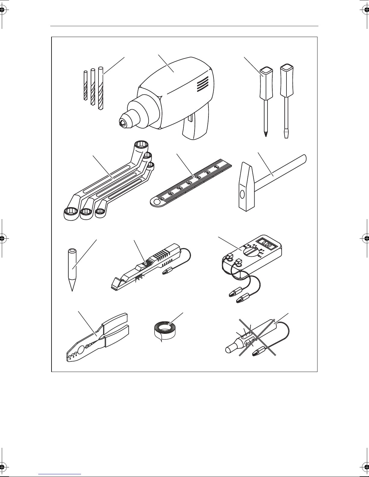
• Use a crimping tool (fig. 1 10, page 2) to connect the cables.
• When connecting to supply line 31 (earth), screw the cable
– To the vehicle’s earth bolt with a cable lug and a gear disc or
– To the sheet metal body work with a cable lug and a self-tapping screw.
Ensure that there is a good earth connection.
When the negative terminal of the battery is disconnected, all data stored in the
volatile memories will be lost.
• The following data must be set again, depending on the vehicle equipment
options:
–Radio code
– Vehicle clock
–Timer
– On-board computer
– Seat position
You can find instructions for making these settings in the appropriate operating
instructions.
Observe the following installation instructions:
• Secure the parts of the camera installed in the vehicle in such a way that they
cannot become loose under any circumstances (sudden braking, accidents) and
cause injuries to the occupants of the vehicle.
• Secure any parts of the system covered by the bodywork in such a manner that
they cannot be come loose or damage other parts and cables and impair vehicle
functions (steering, pedals, etc.).
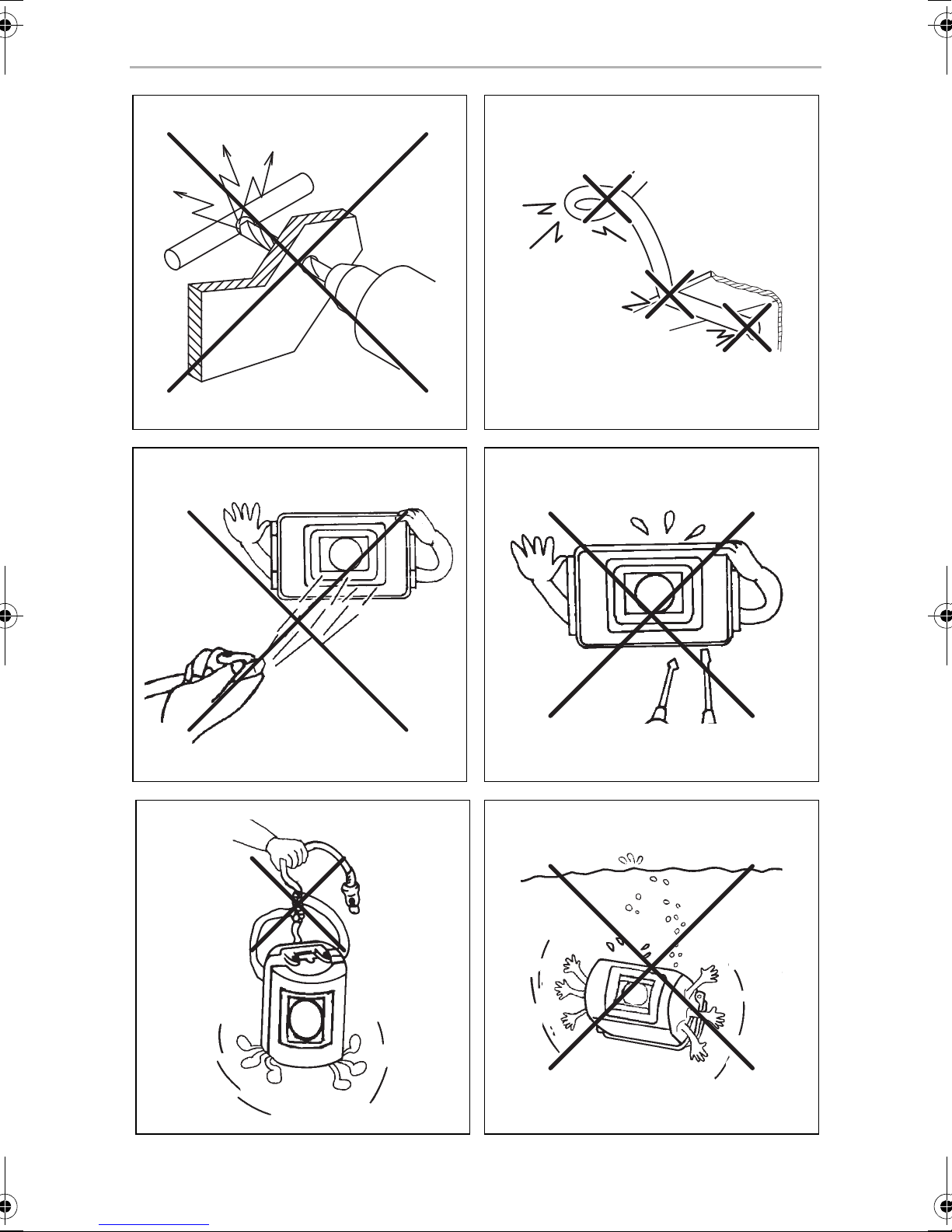
• To prevent damage, when drilling ensure that there is sufficient room for the drill
head to come out on the other side (fig. 2, page 3).
• Deburr all drill holes and treat them with a rust-protection agent.
• Always follow the safety instructions of the vehicle manufacturer.
Some work (e.g. on retention systems such as the AIRBAG etc.) may only be
performed by qualified specialists.
10

EN
CAM55/55W Safety and installation instructions
Observe the following instructions when working with electrical parts:
• When testing the voltage in electrical cables, only use a diode test lamp
(fig. 1 8, page 2) or a voltmeter (fig. 1 9, page 2).
Test lamps with an illuminant (fig. 1 12, page 2) take up voltages which are too
high and which can damage the vehicle’s electronic system.
• When making electrical connections, ensure that
– They are not kinked or twisted
– They do not rub on edges
– They are not laid in sharp edged ducts without protection
(see fig. 3, page 3)
• Insulate all connections.
• Secure the cables against mechanical wear with cable binders or insulating tape,
for example to existing cables.
The camera is watertight. However, the sealings on the camera cannot withstand a
high-pressure cleaner (fig. 4, page 3). Therefore, you should observe the following
instructions when handling the camera:
• People (including children) whose physical, sensory or mental capacities or
whose lack of experience or knowledge prevent them from using this product
safely should not use it without the supervision or instruction of a responsible
person.
• Do not open the camera, as this impairs the sealing and the function of the
camera (fig. 5, page 3).
• Do not pull at the cables, as this impairs the sealing and the function of the camera
(fig. 6, page 3).
• The camera is not suitable for submerged operation (fig. 7, page 3).
11
EN
Scope of delivery CAM55/55W
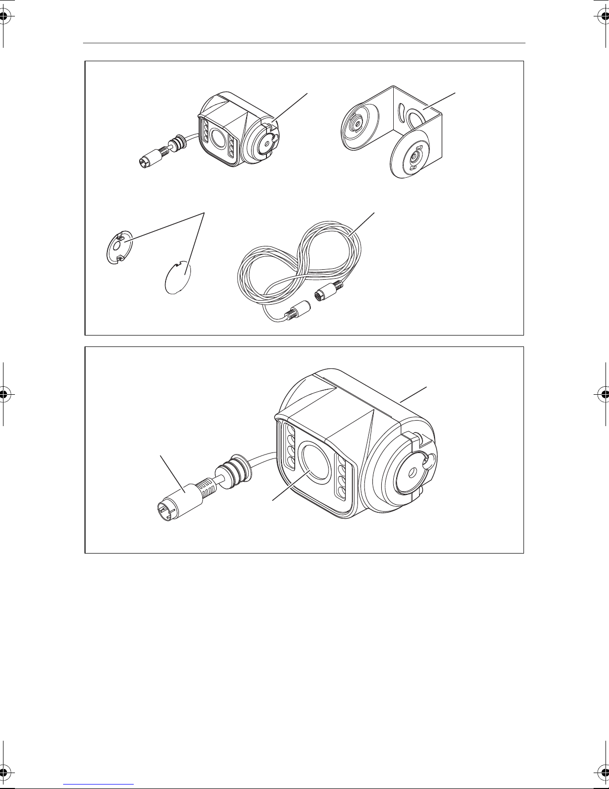
3Scope of delivery
No. in
fig. 8, page 4
1 1 Colour camera CAM55
2 1 Camera bracket
32Side covers
4 1 Extension cable 9600000208
Quantity Description Reference no.
9600000555
Colour camera CAM55W
9600000556
4Accessories
Available as accessory (not included in scope of delivery):
Description Reference no.
Extension cable 5 m 9600000206
Extension cable 10 m 9600000207
Extension cable 20 m 9600000208
Spiral cable for trailer operation SPK170 9600000235
5 Intended use
The CMOS CAM55 (ref. no. 9600000555) and CAM55W (ref. no. 9600000556)
colour cameras are primarily intended for use in vehicles. They can be used in video
systems to observe the space around the vehicle from the driver's seat when
manoeuvring or parking, for example.
WARNING!
!
Risk of injury!
Since rear view systems are designed merely as an additional aid for
reversing, it does not relieve you of the duty to take proper care
when reversing.
12
EN
CAM55/55W Technical description
6 Technical description
The camera with integrated microphone, which is encased in aluminium housing,
transmits image and sound to a monitor via a cable. The built-in infrared LEDs
improve night vision.
The camera transmits the image as if you are looking in the rear mirror.
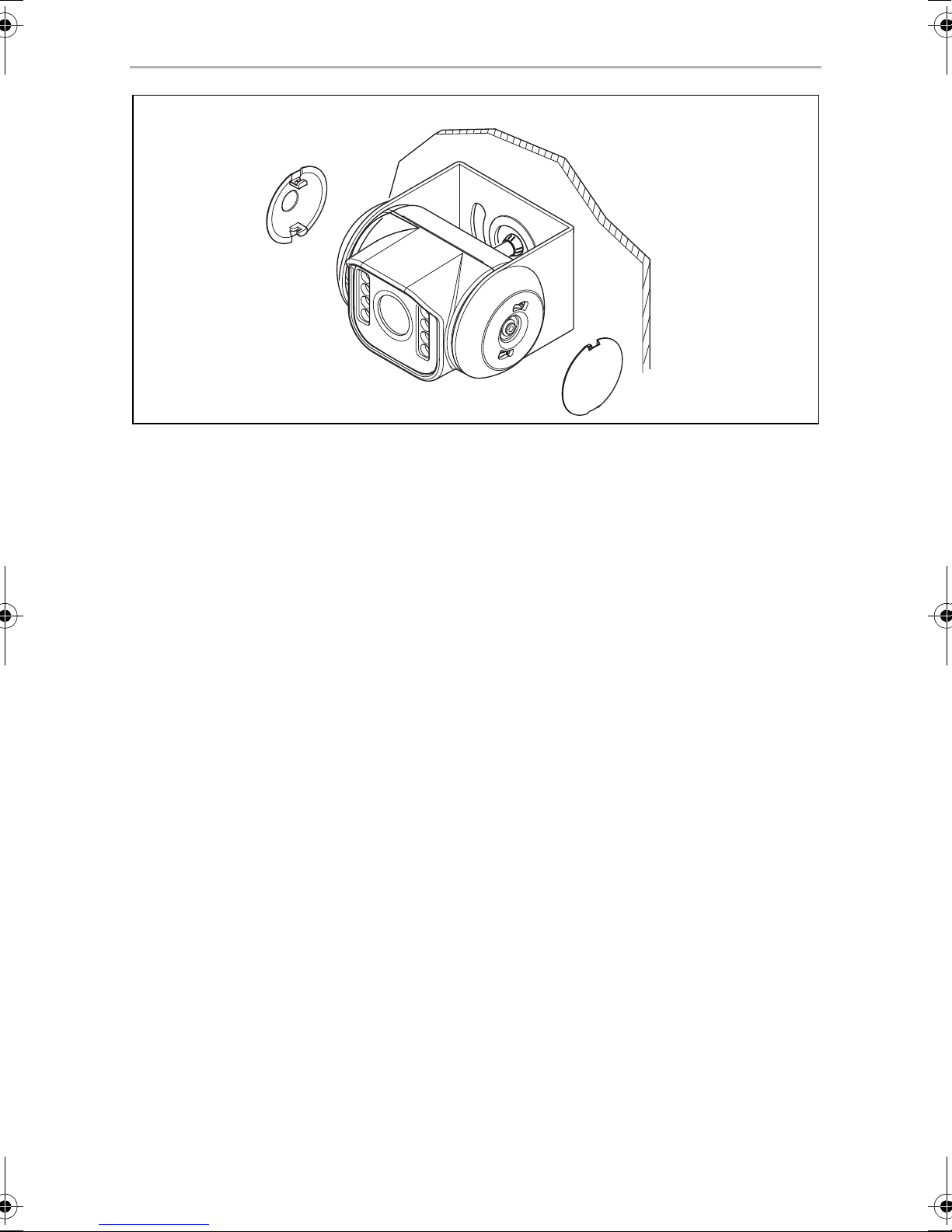
The camera consists of the following main elements:
No. in
fig. 9, page 4
1 6-pin connection cable
2 Infrared LEDs
3 Microphone
Description
7 Notes on the electrical connections
7.1 Laying cables
NOTICE! Risk of damage!
A
• To prevent damage, when drilling ensure that there is sufficient
space on the other side for the drill head to come out.
• Cables and connections which are not properly installed will cause
malfunctions or damage to components. Correct installation of
cables and connections is the basic prerequisite for lasting and
trouble-free operation of the retrofitted components.
• The cables may not be exposed for long periods to solvents such as
benzine, as the solvents can damage the cable.
Please observe the following instructions:
• As far as possible, use original openings or alternative openings for the
connecting cable duct, e.g. the paneling edges, ventilation grilles or blank
panels. If no openings are available, you must drill holes for the cables. Check
beforehand that there is sufficient room for the drill head to come out on the other
side.
13

EN
Notes on the electrical connections CAM55/55W
• Wherever possible lay cables inside the vehicle, as they are better protected
inside than outside the vehicle.
If you do need to lay a cable outside the vehicle, ensure that it is well secured
(use additional cable ties, insulating tape, etc.).
• To prevent damage to the cables, when laying them ensure that there is sufficient
distance to hot or moving vehicle components (exhaust pipes, drive shafts, light
systems, fans, heater etc.). Use corrugated piping or other protective materials to
protect against mechanical wear.
• Screw on the plug connections of the connecting cables to protect against water
penetration (fig. g, page 6).
• When laying electric connections, ensure that
– They are not kinked or twisted
– They do not rub on edges
– They are not laid in sharp edged ducts without protection (fig. 3, page 3)
• Attach the cables securely in the vehicles to prevent tripping hazards. Use cable
binders, insulating tape or glue the cables in place.
• Protect every through-hole made in the bodywork against water penetration,
e.g. by using a cable with a sealant and by spraying the cable and the cable
sleeve with sealant.
NOTE
I
Do not start sealing the through-holes until all installation work has been
finished for the camera, and the required cable lengths have been
established.
14

EN
CAM55/55W Mounting the camera
8Mounting the camera
8.1 Tools required
For installation and assembly you will require the following tools:
• Drill bit set (fig. 1 1, page 2)
• Drill (fig. 1 2, page 2)
• Screwdriver (fig. 1 3, page 2)
• Set of ring or open-ended spanners (fig. 1 4, page 2)
• Measuring ruler (fig. 1 5, page 2)
• Hammer (fig. 1 6, page 2)
• Centre punch (fig. 1 7, page 2)
To make and test the electrical connection, the following tools are required:
• Diode test lamp (fig. 1 8, page 2) or voltmeter (fig. 1 9, page 2)
• Insulating tape (fig. 1 11, page 2)
• Cable bushing sleeves, if necessary
To fasten the cables you may require additional cable binders.
8.2 Mounting the camera
CAUTION!
!
I
Select a location for the camera and attach it so securely that it cannot
under any circumstances fall off and injure bystanders (e.g. by being
knocked off by branches brushing over the roof of the vehicle).
NOTE
If installing the camera alters the vehicle height or length specified in the
vehicle documents, your vehicle must be inspected by the appropriate
authorities.
Make sure that you are in possession of documents verifying that your
vehicle has passed this inspection.
15

EN
Mounting the camera CAM55/55W
Observe the following installation instructions:
• To provide a suitable viewing angle, the camera must be attached at a height of
at least 2 m.
Ensure that you have a firm place from which to work when mounting the camera.
• Ensure that the installation location of the camera is sufficiently firm (e.g. to
prevent the camera from being knocked down by branches that may brush
over the roof of the vehicle).
• Mount the camera bracket horizontally and in the middle of the rear of the vehicle
(fig. 0, page 5).
• The most secure type of attachment is with screws fitted through the body.
Please observe the following instructions:
– There must be sufficient space for the mounting procedure behind the
chosen installation location.
– Suitable measures must be taken to prevent water penetrating through any
holes made (e.g. by using screws and sealant and/or spraying the outer
attachment parts with a sealant).
– The location on the body where you wish to attach the camera must be rigid
enough to allow the camera to be tightly fastened.
• Check beforehand that there is sufficient room for the drill head to come out on
the other side (fig. 2, page 3).
• If you are not sure about the location you have chosen, consult the vehicle
manufacturer or dealer.
NOTE
We recommend greasing the threads of the bolts to prevent corrosion.
I
When mounting the camera, proceed as follows:
➤ Hold the camera on the chosen location and mark at least two different points for
the drill holes (fig. a, page 5).
➤ Using a hammer and centre punch, gently pre-punch the previously marked
points to prevent the drill head from slipping off.
16

EN
CAM55/55W Mounting the camera
If you want to screw on the camera with self-tapping screws
(fig. b, page 5)
NOTICE! Risk of damage!
A
➤ Drill Ø 2 mm holes at the points you have just marked.
➤ Deburr all drill holes and apply rust-protection.
➤ Screw on the camera bracket using 4 x 10 mm self-tapping screws.
If you would like to attach the camera with threaded screws fitted through
the construction (fig. c, page 5)
A
The holder may only be attached to steel panels with a minimum
thickness of 1.5 mm using self-tapping screws.
NOTICE! Risk of damage!
Ensure that that nuts cannot be pulled through the body shell when they
are tightened.
Use larger washers or metal plates if necessary.
➤ Drill Ø 6.5 mm holes at the points you have just marked.
➤ Deburr all drill holes and apply rust-protection.
➤ Screw on the camera bracket using M6 x 20 mm threaded screws.
Depending on the thickness of the construction, you may require longer
threaded screws.
Creating a through-hole for the camera connection cable
(fig. d, page 5)
NOTE
I
A
If possible, use available openings – such as ventilation grilles – to feed
the connection cables through. If there are no existing openings, you
must drill a hole with a 16 mm diameter.
NOTICE! Risk of damage!
Ensure that there is sufficient space on the other side for the drill head to
come out
➤ Drill a hole of Ø 16 mm near the camera.
17

EN
Mounting the camera CAM55/55W
➤ Deburr all drill holes that have been made in the sheet metal and apply
rust-protection.
➤ Place cable sleeves in all sharp edged ducts.
Mounting the camera
NOTICE! Risk of damage!
A
➤ Push the camera into the camera bracket.
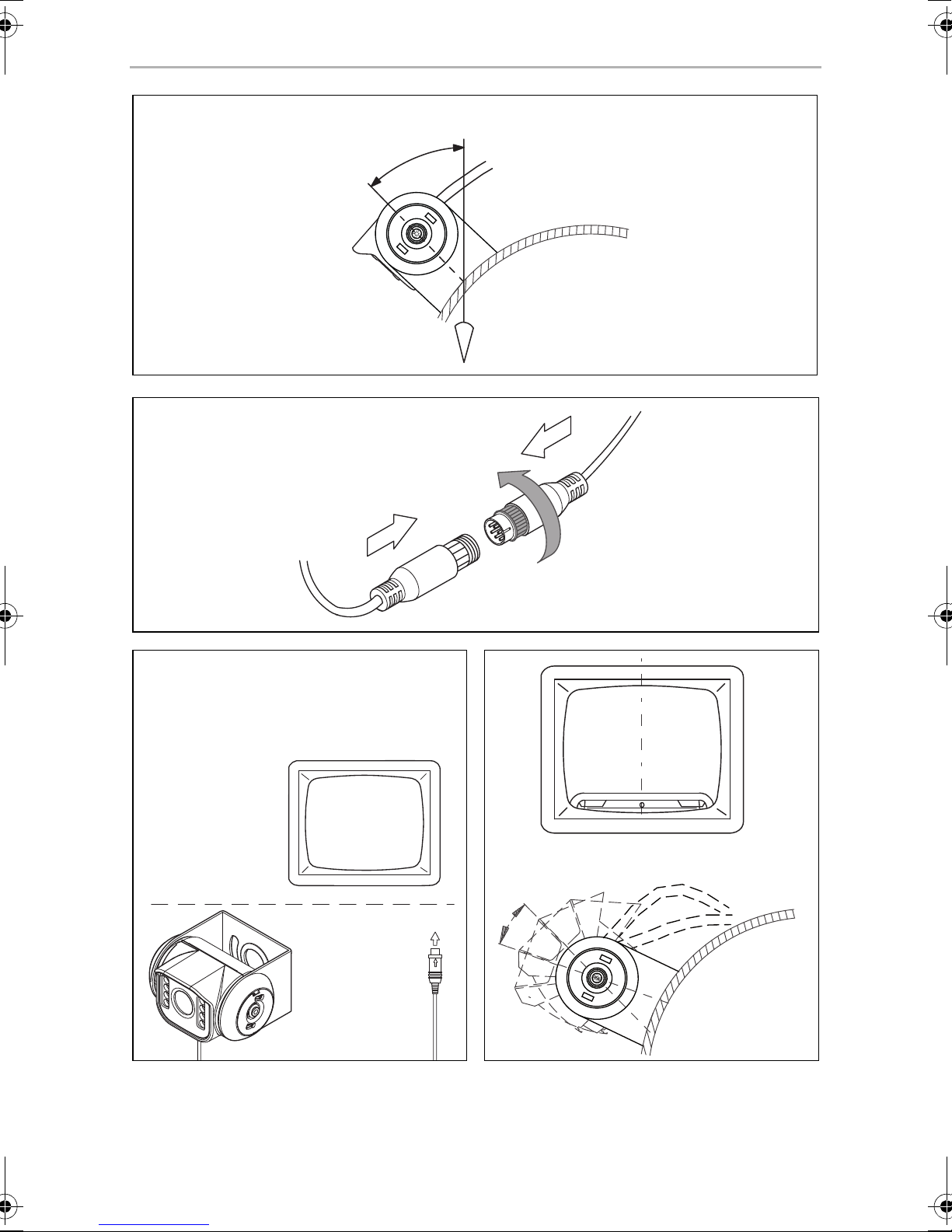
➤ Secure the camera loosely in the holes at the side (fig. e, page 5) by using the
two M4 x 6 mm screws.
➤ Align the camera provisorily so that the lens is at an angle of approx. 50° to the
perpendicular axis of the vehicle (fig. f, page 6).
Only use the screws supplied to mount the camera in the camera
bracket. Longer screws will damage the camera.
Connecting the camera
NOTE
I
➤ Guide the camera cable into the vehicle interior.
➤ Insert the plug of the camera cable into the socket of the extension cable.
➤ Screw on the plug connections of the connecting cables to protect against water
penetration (fig. g, page 6).
• Lay the camera cable so that should you need to remove the camera,
you can access the plug connection between the camera and the
extension cable easily. This considerably eases dismantling work.
• To minimise corrosion in the plug, apply a small amount of grease –
such as pin grease – inside the plug.
• Additional extension cables are available on request (see chapter
“Accessories” on page 12).
18

EN
CAM55/55W Cleaning and caring for the camera
Aligning the camera
NOTE
I
➤ Use the monitor image to align the camera:
The monitor image should show the bottom edge of the rear or the bumper of
your vehicle (A). The middle of the bumper should be in the middle of the
screen. (fig. i, page 6).
➤ Check the function of the camera after you have connected it to a monitor.
Fastening the camera
➤ Tighten the two fastening screws in the holes at the side camera holder.
➤ Click the side covers into the openings at the side provided for this purpose
(fig. j, page 7) and fasten them in place by turning them.
If necessary before aligning the camera connect the camera to a monitor
and to a power supply (see connecting diagram, fig. h, page 6)
➤ To remove the side covers, insert two blunt and flat objects into the openings on
the covers provided for this purpose, and turn them.
9 Cleaning and caring for the camera
NOTICE! Risk of damage!
A
➤ Clean the camera with a soft, damp cloth from time to time.
Do not use sharp or hard objects to clean the device as these may
damage the device.
10 Guarantee
The statutory warranty period applies. If the product is defective, please contact the
manufacturer's branch in your country (see the back of the instruction manual for the
addresses) or your retailer.
For repair and guarantee processing, please send the following items:
• Defect components
• A copy of the receipt with purchasing date
• A reason for the claim or description of the fault
19
EN
Disposal CAM55/55W
13
11 Disposal
➤ Place the packaging material in the appropriate recycling waste bins wherever
possible.
If you wish to finally dispose of the product, ask your local recycling centre
or specialist dealer for details about how to do this in accordance with the
M
applicable disposal regulations.
12 Technical data
PerfectView CAM55 PerfectView CAM55 W
Ref. no.: 9600000555 9600000556
Image sensor: 1/4" CMOS
Pixels: 640 (H) x 480 (V)
Video standard: PAL, 1 Vpp
Light sensitivity: < 1 Lux / 0 Lux with infrared LEDs
Picture angle: approx. 120° diagonal
approx. 100° horizontal
approx. 70° vertical
Operating voltage: 10 – 32 Vg
Power consumption: max. 1.8 W
Operating temperature: –30 °C to +70 °C
Protection class: IP69K
Resistance against vibration: 10 g
Dimensions W x H x D
(with camera bracket):
Weight: approx. 165 g
80 x 50 x 62 mm
Approval
The device has the E13 approval.
20

DE
CAM55/55W
Bitte lesen Sie diese Anleitung vor Einbau und Inbetriebnahme sorgfältig
durch und bewahren Sie sie auf. Geben Sie sie im Falle einer Weitergabe
des Produktes an den Nutzer weiter.
Inhaltsverzeichnis
1 Erklärung der Symbole . . . . . . . . . . . . . . . . . . . . . . . . . . . . . . . . . . . . . . . . . 22
2 Sicherheits- und Einbauhinweise . . . . . . . . . . . . . . . . . . . . . . . . . . . . . . . . . 22
3 Lieferumfang . . . . . . . . . . . . . . . . . . . . . . . . . . . . . . . . . . . . . . . . . . . . . . . . . 25
4 Zubehör. . . . . . . . . . . . . . . . . . . . . . . . . . . . . . . . . . . . . . . . . . . . . . . . . . . . . 25
5 Bestimmungsgemäßer Gebrauch . . . . . . . . . . . . . . . . . . . . . . . . . . . . . . . . 25
6 Technische Beschreibung . . . . . . . . . . . . . . . . . . . . . . . . . . . . . . . . . . . . . . 26
7 Hinweise zum elektrischen Anschluss . . . . . . . . . . . . . . . . . . . . . . . . . . . . . 26
8 Kamera montieren. . . . . . . . . . . . . . . . . . . . . . . . . . . . . . . . . . . . . . . . . . . . . 28
9 Kamera pflegen und reinigen . . . . . . . . . . . . . . . . . . . . . . . . . . . . . . . . . . . . 32
10 Gewährleistung. . . . . . . . . . . . . . . . . . . . . . . . . . . . . . . . . . . . . . . . . . . . . . . 32
11 Entsorgung . . . . . . . . . . . . . . . . . . . . . . . . . . . . . . . . . . . . . . . . . . . . . . . . . . 33
12 Technische Daten . . . . . . . . . . . . . . . . . . . . . . . . . . . . . . . . . . . . . . . . . . . . . 33
21
DE
Erklärung der Symbole CAM55/55W
1 Erklärung der Symbole
WARNUNG!
!
Sicherheitshinweis: Nichtbeachtung kann zu Tod oder schwerer
Verletzung führen.
VORSICHT!
Sicherheitshinweis: Nichtbeachtung kann zu Verletzungen führen.
!
ACHTUNG!
A
Nichtbeachtung kann zu Materialschäden führen und die Funktion des
Produktes beeinträchtigen.
HINWEIS
Ergänzende Informationen zur Bedienung des Produktes.
I
2 Sicherheits- und Einbauhinweise
Beachten Sie die vom Fahrzeughersteller und vom Kfz-Handwerk
vorgeschriebenen Sicherheitshinweise und Auflagen!
Der Hersteller übernimmt in folgenden Fällen keine Haftung für Schäden:
• Montage- oder Anschlussfehler
• Beschädigungen am Produkt durch mechanische Einflüsse und Über-
spannungen
• Veränderungen am Produkt ohne ausdrückliche Genehmigung vom Hersteller
• Verwendung für andere als die in der Anleitung beschriebenen Zwecke
Beachten Sie folgende Hinweise:
• Klemmen Sie wegen der Kurzschlussgefahr vor Arbeiten an der Fahrzeugelektrik
immer den Minuspol ab.
Bei Fahrzeugen mit Zusatzbatterie müssen Sie an dieser ebenfalls den Minuspol
abklemmen.
22

DE
CAM55/55W Sicherheits- und Einbauhinweise
• Unzureichende Leitungsverbindungen können zur Folge haben, dass durch
Kurzschluss
– Kabelbrände entstehen,
– der Airbag ausgelöst wird,
– elektronische Steuerungseinrichtungen beschädigt werden,
– elektrische Funktionen ausfallen (Blinker, Bremslicht, Hupe, Zündung, Licht).
• Verwenden Sie bei Arbeiten an den folgenden Leitungen nur isolierte Kabelschuhe, Stecker und Flachsteckhülsen:
– 30 (Eingang von Batterie Plus direkt),
– 15 (Geschaltetes Plus, hinter Batterie),
– 31 (Rückleitung ab Batterie, Masse),
– 58 (Rückfahrscheinwerfer).
Verwenden Sie keine Lüsterklemmen.
• Verwenden Sie eine Krimpzange (Abb. 1 10, Seite 2) zum Verbinden der
Kabel.
• Schrauben Sie das Kabel bei Anschlüssen an Leitung 31 (Masse)
– mit Kabelschuh und Zahnscheibe an eine fahrzeugeigene Masseschraube
oder
– mit Kabelschuh und Blechschraube an das Karosserieblech.
Achten Sie auf eine gute Masseübertragung!
Beim Abklemmen des Minuspols der Batterie verlieren alle flüchtigen Speicher der
Komfortelektronik ihre gespeicherten Daten.
• Folgende Daten müssen Sie je nach Fahrzeugausstattung neu einstellen:
–Radiocode
–Fahrzeuguhr
– Zeitschaltuhr
– Bordcomputer
– Sitzposition
Hinweise zur Einstellung finden Sie in der jeweiligen Bedienungsanleitung.
Beachten Sie folgende Hinweise bei der Montage:
• Befestigen Sie die im Fahrzeug montierten Teile der Kamera so, dass sie sich
unter keinen Umständen (scharfes Abbremsen, Verkehrsunfall) lösen und zu
Verletzungen der Fahrzeuginsassen führen können.
• Befestigen Sie verdeckt unter Verkleidungen anzubringende Teile des Systems
so, dass sie sich nicht lösen oder andere Teile und Leitungen beschädigen und
keine Fahrzeugfunktionen (Lenkung, Pedale usw.) beeinträchtigen können.
23

DE
Sicherheits- und Einbauhinweise CAM55/55W
• Achten Sie beim Bohren auf ausreichenden Freiraum für den Bohreraustritt,
um Schäden zu vermeiden (Abb. 2, Seite 3).
• Entgraten Sie jede Bohrung und behandeln Sie diese mit Rostschutzmittel.
• Beachten Sie immer die Sicherheitshinweise des Fahrzeugherstellers.
Einige Arbeiten (z. B. an Rückhaltesystemen wie AIRBAG usw.) dürfen nur von
geschultem Fachpersonal durchgeführt werden.
Beachten Sie folgende Hinweise bei der Arbeit an elektrischen Teilen:
• Benutzen Sie zum Prüfen der Spannung in elektrischen Leitungen nur eine
Diodenprüflampe (Abb. 1 8, Seite 2) oder ein Voltmeter (Abb. 1 9, Seite 2).
Prüflampen mit einem Leuchtkörper (Abb. 1 12, Seite 2) nehmen zu hohe
Ströme auf, wodurch die Fahrzeugelektronik beschädigt werden kann.
• Beachten Sie beim Verlegen der elektrischen Anschlüsse, dass diese
– nicht geknickt oder verdreht werden,
– nicht an Kanten scheuern,
– nicht ohne Schutz durch scharfkantige Durchführungen verlegt werden
(Abb. 3, Seite 3).
• Isolieren Sie alle Verbindungen und Anschlüsse.
• Sichern Sie die Kabel gegen mechanische Beanspruchung durch Kabelbinder
oder Isolierband, z. B. an vorhandenen Leitungen.
Die Kamera ist wasserdicht. Die Dichtungen der Kamera halten aber nicht einem
Hochdruckreiniger stand (Abb. 4, Seite 3). Beachten Sie deshalb folgende
Hinweise zum Umgang mit der Kamera:
• Personen (einschließlich Kinder), die aufgrund ihrer physischen, sensorischen
oder geistigen Fähigkeiten oder ihrer Unerfahrenheit oder Unkenntnis nicht in
der Lage sind, das Produkt sicher zu benutzen, sollten dieses Produkt nicht ohne
Aufsicht oder Anweisung durch eine verantwortliche Person nutzen.
• Öffnen Sie die Kamera nicht, da dieses ihre Dichtigkeit und die Funktionsfähigkeit beeinträchtigt (Abb. 5, Seite 3).
• Ziehen Sie nicht an den Kabeln, da dieses die Dichtigkeit und die Funktionsfähigkeit der Kamera beeinträchtigt (Abb. 6, Seite 3).
• Die Kamera ist nicht für den Betrieb unter Wasser geeignet (Abb. 7, Seite 3).
24
DE
CAM55/55W Lieferumfang
3 Lieferumfang
Nr. in
Abb. 8, Seite 4
1 1 Farbkamera CAM55
21Kamerahalter
3 2 Seitenabdeckungen
4 1 Verlängerungskabel 9600000208
Menge Bezeichnung Artikel-Nr.
9600000555
Farbkamera CAM55W
9600000556
4Zubehör
Als Zubehör erhältlich (nicht im Lieferumfang enthalten):
Bezeichnung Artikel-Nr.
Verlängerungskabel 5 m 9600000206
Verlängerungskabel 10 m 9600000207
Verlängerungskabel 20 m 9600000208
Spiralkabel für Anhängerbetrieb SPK170 9600000235
5 Bestimmungsgemäßer Gebrauch
Die CMOS Farbkameras CAM55 (Art.-Nr. 9600000555) und and CAM55W
(Art.-Nr. 9600000556) sind vorrangig für den Einsatz in Fahrzeugen gedacht. Sie
sind einsetzbar in Videosystemen, die zur Beobachtung des Bereiches um das Fahrzeug vom Fahrersitz aus dienen, z. B. beim Rangieren oder Einparken.
WARNUNG!
!
Gefahr von Personenschäden durch das Fahrzeug.
Rückfahrvideosysteme stellen eine Unterstützung beim Rückwärtsfahren
dar, sie entbinden Sie jedoch nicht von der besonderen Vorsichts-
pflicht beim Rückwärtsfahren.
25
DE
Technische Beschreibung CAM55/55W
6 Technische Beschreibung
Die Kamera mit integriertem Mikrofon ist in einem Aluminiumgehäuse untergebracht
und überträgt Bild und Ton über ein Kabel zu einem Monitor. Durch die Infrarot-LEDs
wird die Nachtsicht verbessert.
Die Kamera übermittelt das Bild, als ob Sie in den Rückspiegel blicken.
Die Kamera besteht aus u. a. folgenden Elementen:
Nr. in
Abb. 9, Seite 4
1 6-poliges Anschlusskabel
2 Infrarot-LEDs
3 Mikrofon
Bezeichnung
7 Hinweise zum elektrischen Anschluss
7.1 Kabel verlegen
ACHTUNG! Beschädigungsgefahr!
A
• Wenn Sie Löcher bohren, prüfen Sie vorher, ob ausreichender
Freiraum für den Bohreraustritt vorhanden ist.
• Nicht fachgerechte Kabelverlegungen und Kabelverbindungen
führen immer wieder zu Fehlfunktionen oder Beschädigungen von
Bauteilen. Eine korrekte Kabelverlegung bzw. Kabelverbindung ist
die Grundvoraussetzung für eine dauerhafte und fehlerfreie Funktion
der nachgerüsteten Komponenten.
• Die Kabel dürfen nicht über längere Zeit mit Lösungsmitteln wie
z. B. Benzin in Berührung kommen, da Lösungsmittel die Kabel
beschädigen würden.
Beachten Sie deshalb folgende Hinweise:
• Verwenden Sie für die Durchführung der Anschlusskabel nach Möglichkeit
Originaldurchführungen oder andere Durchführungsmöglichkeiten, z. B.
Verkleidungskanten, Lüftungsgitter oder Blindschalter. Wenn keine Durchführungen vorhanden sind, müssen Sie für die jeweiligen Kabel entsprechende
Löcher bohren. Schauen Sie vorher nach, ob ausreichender Freiraum für den
Bohreraustritt vorhanden ist.
26

DE
CAM55/55W Hinweise zum elektrischen Anschluss
• Verlegen Sie die Kabel nach Möglichkeit immer im Fahrzeuginneren, denn dort
sind sie besser geschützt als außen am Fahrzeug.
Wenn Sie die Kabel trotzdem außerhalb des Fahrzeuges verlegen, achten Sie auf
eine sichere Befestigung (durch zusätzliche Kabelbinder, Isolierband usw.).
• Um Beschädigungen am Kabel zu vermeiden, halten Sie beim Verlegen der
Kabel immer ausreichend Abstand zu heißen und sich bewegenden Fahrzeugteilen (Auspuffrohre, Antriebswellen, Lichtmaschine, Lüfter, Heizung usw.).
Verwenden Sie zum mechanischen Schutz Wellrohr oder ähnliche Schutzmaterialien.
• Verschrauben Sie die Steckverbindungen der Verbindungskabel zum Schutz
gegen das Eindringen von Wasser (Abb. g, Seite 6).
• Beachten Sie beim Verlegen der Kabel, dass diese
– nicht stark geknickt oder verdreht werden,
– nicht an Kanten scheuern,
– nicht ohne Schutz durch scharfkantige Durchführungen verlegt werden
(Abb. 3, Seite 3).
• Befestigen Sie die Kabel sicher im Fahrzeug, um ein Verfangen (Sturzgefahr)
zu vermeiden. Dieses kann erfolgen durch den Einsatz von Kabelbindern,
Isolierband oder durch Ankleben mit Klebstoff.
• Schützen Sie jeden Durchbruch an der Außenhaut durch geeignete Maßnahmen
gegen Wassereinbruch, z. B. durch Einsetzen des Kabels mit Dichtungsmasse
und durch Abspritzen des Kabels und der Durchführungstülle mit Dichtungsmasse.
HINWEIS
I
Beginnen Sie mit dem Abdichten der Durchbrüche erst, nachdem alle
Einstellarbeiten an der Kamera abgeschlossen sind und die benötigten
Längen der Anschlusskabel festliegen.
27

DE
Kamera montieren CAM55/55W
8 Kamera montieren
8.1 Benötigtes Werkzeug
Für Einbau und Montage benötigen Sie folgende Werkzeuge:
• Satz Bohrer (Abb. 1 1, Seite 2)
• Bohrmaschine (Abb. 1 2, Seite 2)
• Schraubendreher (Abb. 1 3, Seite 2)
• Satz Ring- oder Maulschlüssel (Abb. 1 4, Seite 2)
• Maßstab (Abb. 1 5, Seite 2)
• Hammer (Abb. 1 6, Seite 2)
• Körner (Abb. 1 7, Seite 2)
Für den elektrischen Anschluss und seine Überprüfung benötigen Sie folgende
Hilfsmittel:
• Diodenprüflampe (Abb. 1 8, Seite 2) oder Voltmeter (Abb. 1 9, Seite 2)
• Isolierband (Abb. 1 11, Seite 2)
• Ggf. Kabeldurchführungstüllen
Zur Befestigung der Kabel benötigen Sie ggf. noch weitere Kabelbinder.
8.2 Kamera montieren
VORSICHT!
!
I
Wählen Sie den Platz der Kamera so und befestigen Sie diese so sicher,
dass unter keinen Umständen in der Nähe stehende Personen verletzt
werden können, z. B. weil über das Fahrzeugdach streifende Äste die
Kamera abreißen.
HINWEIS
Wenn durch den Anbau der Kamera die in den Fahrzeugpapieren
eingetragene Fahrzeughöhe oder Fahrzeuglänge verändert wird,
muss eine neue Abnahme durch die zuständigen Stellen (TÜV,
DEKRA usw.) erfolgen.
Lassen Sie die neue Abnahme durch Ihr zuständiges Straßenverkehrsamt in die Fahrzeugpapiere eintragen.
28
DE
CAM55/55W Kamera montieren
Beachten Sie folgende Hinweise bei der Montage:
• Bringen Sie die Kamera für einen vernünftigen Blickwinkel in mindestens zwei
Metern Höhe an.
Achten Sie bei der Montage auf einen ausreichend standfesten Arbeitsplatz.
• Achten Sie darauf, dass der Montageort der Kamera ausreichende Festigkeit
bietet (z. B. können sich über das Fahrzeugdach streifende Äste in der Kamera
verfangen).
• Montieren Sie den Kamerahalter waagerecht und mittig am Heck des
Fahrzeuges (Abb. 0, Seite 5).
• Die sicherste Art der Befestigung sind Schrauben, die durch den Aufbau gehen.
Beachten Sie dabei folgende Hinweise:
– Hinter der gewählten Montageposition muss ausreichend Freiraum für die
Montage vorhanden sein.
– Jeder Durchbruch muss durch geeignete Maßnahmen gegen
Wassereinbruch geschützt werden (z. B. durch Einsetzen der Schrauben mit
Dichtungsmasse und/oder Abspritzen der äußeren Befestigungsteile mit
Dichtungsmasse).
– Der Aufbau an der Befestigungsstelle muss genügend Festigkeit bieten,
damit sich der Kamerahalter genügend fest anziehen lässt.
• Kontrollieren Sie vorher, ob ausreichender Freiraum für den Bohreraustritt
vorhanden ist (Abb. 2, Seite 3).
• Wenn Sie sich nicht sicher über den von Ihnen gewählten Montageort sind,
erkundigen Sie sich beim Aufbauhersteller oder dessen Vertretung.
HINWEIS
I
Gehen Sie bei der Montage wie folgt vor:
➤ Halten Sie den Kamerahalter an den gewählten Montageort und markieren Sie
mindestens zwei verschiedene Bohrpunkte (Abb. a, Seite 5).
➤ Körnen Sie an den zuvor angezeichneten Punkten mit Hammer und Körner vor,
um ein Verlaufen des Bohrers zu verhindern.
Um die Korrosion der Schrauben zu minimieren, fetten Sie die Gewinde
ein.
29

DE
Kamera montieren CAM55/55W
Wenn Sie die Kamera mit Blechschrauben anschrauben möchten
(Abb. b, Seite 5)
ACHTUNG! Beschädigungsgefahr!
A
➤ Bohren Sie an den zuvor angezeichneten Punkten jeweils ein Loch von Ø 3 mm.
➤ Entgraten Sie alle Bohrlöcher und versehen Sie sie mit Rostschutz.
➤ Schrauben Sie den Kamerahalter mit Blechschrauben der Größe 4 x 10 mm an.
Wenn Sie die Kamera mit Gewindeschrauben durch den Aufbau
befestigen möchten (Abb. c, Seite 5)
A
Die Befestigung mit Blechschrauben darf nur in Stahlblechen mit einer
Mindestdicke von 1,5 mm erfolgen.
ACHTUNG! Beschädigungsgefahr!
Achten Sie darauf, dass sich die Muttern beim Anziehen nicht durch den
Aufbau ziehen können.
Verwenden Sie ggf. größere Unterlegscheiben oder Blechplatten.
➤ Bohren Sie an den zuvor angezeichneten Punkten jeweils ein Loch von
Ø6,5mm.
➤ Entgraten Sie alle Bohrlöcher und versehen Sie sie mit Rostschutz.
➤ Schrauben Sie den Kamerahalter mit den Gewindeschrauben M6 x 20 mm an.
Je nach Aufbaustärke benötigen Sie längere Gewindeschrauben.
Durchbruch für das Anschlusskabel der Kamera anfertigen (Abb. d,
Seite 5)
HINWEIS
I
A
Verwenden Sie für die Durchführung der Anschlusskabel nach Möglichkeit vorhandene Durchführungsmöglichkeiten, z. B. Lüftungsgitter.
Wenn keine Durchführungen vorhanden sind, müssen Sie ein Loch von
Ø16mm bohren.
ACHTUNG! Beschädigungsgefahr!
Kontrollieren Sie vorher, ob ausreichender Freiraum für den Bohreraustritt vorhanden ist.
➤ Bohren Sie in der Nähe der Kamera ein Loch von Ø 16 mm.
30
 Loading...