

Page 1
2015
GRAND CARAVAN
USER
GUIDE
Page 2
IMPORTANT
This U s er G ui d e is i n tend ed to f am il iari ze you wi th the i mp orta nt feat ur e s
of y our veh ic le . T he D VD en cl o sed con ta i ns y our Owne r’s Manu al ,
Navigation/Uconnect
Road si d e A s sist an c e ( n ew v ehic le s p ur ch ased in t he U . S.) or Road si d e
Assi st a nce ( new v ehic le s pu rc ha sed i n Ca na d a) i n el e ctro ni c fo rm at . We
hope yo u fi nd i t us ef u l. Rep la ce ment DVD ki ts ma y be pu rc ha sed by vis it i ng
www.techauthority.com. DOD GE a nd Gr an d C a rava n a r e reg is te red
trademarks of Chrysler Group LLC. Copyright 2014 Chrysler Group LLC.
If you are the rst registered retail owner of your vehicle, you may
obtain a complimentary printed copy of the Owner’s Manual,
Navigation/Uconnect
1-800-423-6343 (U.S.) or 1-800-387-1143 (Canada) or by
contacting your dealer.
®
M a nual s, W arra nt y B oo k lets , Ti re War ra n ty and
®
Manuals or Warranty Booklet by calling
T h e dr iver's p ri ma ry r esp onsib il it y
is t h e s a f e o p e r a t i o n o f t he
v e hicle. D r i v i ng w hile distracted
c an re sult in l o s s o f v eh ic le
c o n t r o l , r esul ting i n a c ol li si on
and p ersonal i nj ur y. C hr y sler
G r o u p L L C s trongly r ec ommend s
t hat t he d ri ver u se e x t r e m e
c au tion when usin g a ny device or
f e a t u r e t hat may tak e t heir
a t t e n ti on o f f the r oa d. U s e of any
e l e c t r ic al d e v i c e s , such a s
c e l lular t el eph ones, c ompu ters ,
p o r ta bl e rad io s, vehicl e na vig at ion
o r o ther d e v i c es , b y t he d r i v e r
w hile the vehicle is m oving i s
dangerous a n d c ould l e ad t o a
s e r i o u s colli si on. T e xtin g w hi l e
dr i v ing is al so da ng er ous an d
should n ev er b e d one w hi le t h e
v e hicle i s moving . I f you f in d
y o u r s e l f u nable t o d evote your ful l
a t t e n ti on to v e h i c l e o p e ra ti on,
p ull o ff t he r oa d t o a s af e l o ca ti on
and s to p y o u r v ehicl e. S om e s t a t e s
o r p r o v i n c e s p rohi bi t the use of
c e l lular telephones o r t e xtin g
w hile d rivin g. I t i s a lw ay s t he
dr i v e r ' s r esponsib il it y t o c o m p l y
with all local laws.
Page 3

TABLE OF CONTENTS
INTRODUCTION/WELCOME
WELCOME FROM CHRYSLER GROUP
LLC . . . . . . . . . . . . . . . . . . . . . . . 2
CONTROLS AT A GLANCE
DRIVER COCKPIT ...............4
INSTRUMENT CLUSTER ........... 6
GETTING STARTED
KEY FOB . . . . . . . . . . . . . . . . . . . . 8
REMOTE STAR T . . . . . . . . . . . . . . . . 9
KEYLESS ENTER-N-GO™ .........10
VEHICLE SECURITY ALARM ........13
SEA T BELT SYSTEMS ............14
SUPPLEMENTAL RESTRAINT SYSTEM
(SRS) — AIR BAGS .............15
CHILD RESTRAINTS ............18
HEAD RESTRAINTS .............22
FRONT SEA TS ................24
HEA TED SEATS . . . . . . . . . . . . . . . 25
HEA TED STEERING WHEEL ........ 26
TIL T/TELESCOPING STEERING
COLUMN ................... 27
OPERATING YOUR VEHICLE
ENGINE BREAK-IN
RECOMMENDA TIONS ............ 28
TURN SIGNAL/WIPER/WASHER/HIGH BEAM
LEVER .....................28
HEADLIGHT SWITCH AND HALO LIGHT
SWITCH .................... 30
ELECTRONIC RANGE SELECTION (ERS) . . 31
FUEL ECONOMY (ECON) MODE ......32
THREE ZONE AUTOMA TIC TEMPERATURE
CONTROLS (A TC) ...............33
PARKSE NSE
PARKVI EW
BLIND SPOT MONITORING WITH REAR
CROSS PATH .................35
®
REAR PARK ASSIST .... 35
®
REAR BACK-UP CAMERA . . 35
ELECTRONICS
YOUR VEHICLE'S SOUND SYSTEM ....36
®
Uconnect
Uconnect
RADIO .....................41
Uconnect
SiriusXM SA TELLITE RADIO/TRAVEL
LINK ...................... 54
STEERING WHEEL AUDIO CONTROLS . . 58
iPod
Uconnect
Uconnect
Bluetooth
VIDEO ENTERT AINMENT SYSTEM
(VES™) ....................65
ELECTRONIC VEHICLE INFORMA TION
CENTER (EVIC) ................67
PROGRAMMABLE FEA TURES .......67
130 . . . . . . . . . . . . . . . . 38
®
130 WITH SiriusXM SA TELLITE
®
430/430N ............44
®
/USB/MP3 CONTROL .........58
®
Phone ...............59
®
VOICE COMMAND ........62
®
STREAMING AUDIO ...... 65
UNIVERSAL GARAGE DOOR OPENER
(HomeLink
®
).................69
UTILITY
TRAILER TOWING WEIGHTS (MAXIMUM
TRAILER WEIGHT RA TINGS) ........72
RECREA TIONAL TOWING (BEHIND
MOTORHOME, ETC.) ............73
WHAT TO DO IN EMERGENCIES
ROADSIDE ASSISTANCE ..........74
INSTRUMENT CLUSTER WARNING
LIGHTS ....................74
INSTRUMENT CLUSTER INDICA TOR
LIGHTS ....................78
IF YOUR ENGINE OVERHEA TS .......80
TIRE SERVICE KIT ..............80
JACKING AND TIRE CHANGING ......86
JUMP-STAR TING ...............98
SHIFT LEVER OVERRIDE ......... 100
TOWING A DISABLED VEHICLE .....100
FREEING A STUCK VEHICLE .......101
EVENT DA TA RECORDER (EDR) .....102
MAINTAINING YOUR VEHICLE
OPENING THE HOOD ...........103
ENGINE COMPAR TMENT ......... 104
FLUID CAPACITIES ............106
FLUIDS, LUBRICANTS AND GENUINE
PART S . . . . . . . . . . . . . . . . . . . . 1 06
MAINTENANCE PROCEDURES ......108
MAINTENANCE SCHEDULE .......108
MAINTENANCE RECORD .........112
FUSES ....................113
TIRE PRESSURES .............116
SPARE TIRES — IF EQUIPPED ......117
ADDING FUEL ................ 119
WHEEL AND WHEEL TRIM CARE ....120
REPLACEMENT BULBS ..........120
CONSUMER ASSISTANCE
CHRYSLER GROUP LLC CUSTOMER
CENTER ...................121
CHRYSLER CANADA INC. CUSTOMER
CENTER ...................121
PUBLICA TIONS ORDERING ........121
ASSISTANCE FOR THE HEARING
IMPAIRED ..................122
REPORTING SAFETY DEFECTS IN THE
UNITED STATES ..............122
MOPAR® ACCESSORIES
AUTHENTIC ACCESSORIES BY
MOPAR®...................123
FREQUENTLY ASKED QUESTIONS
FREQUENTL Y ASKED QUESTIONS ....124
INDEX
.....................126
Page 4

INTRODUCTION/WELCOME
WELCOME FROM CHRYSLER GROUP LLC
Congratulations on selecting your new Chrysler Group LLC vehicle. Be assured that it
represents precision workmanship, distinctive styling, and high quality - all essentials that
are traditional to our vehicles.
Your new Chrysl er Grou p LLC v ehicle has cha racteri stics t o enhan ce the driver' s contr ol
under some driving conditions. These are to assist the driver and are never a substitute for
attentive driving. They can never take the driver's place. Always drive carefully .
Your new vehicl e has m any fe at ures f or th e comf ort and conven ience of you and y ou r
passengers. Some of these should not be used when driving because they take your eyes
from the road or your attention from driving. Never text while driving or take your eyes more
than momentarily off the road.
This guide illustrates and describes the operation of features and equipment that are
either standard or optional on this vehicle. This guide may also include a description of
features and equipment that are no longer available or were not ordered on this vehicle.
Please disregard any features and equipment described in this guide that are not available
on this vehicle. Chrysler Group LLC reserves the right to make changes in design and
specifications and/or make additions to or improvements to its products without imposing
any obligation upon itself to install them on products previously manufactured.
This User Guide has been prepared to help you quickly become acquainted with the
important features of your vehicle. It contains most things you will need to operate and
maintain the vehicle, including emergency information.
The DVD includes a computer application containing detailed owner's information which
can be viewed on a personal computer or MAC computer. The multimedia DVD also
includes videos which can be played on any standard DVD player (including the
Uconnect
DVD operational information is located on the back of the DVD sleeve.
For complete owner information, refer to your Owner's Manual on the DVD in the owner’s
kit provided at the time of new vehicle purchase. For your convenience, the information
contained on the DVD may also be printed and saved for future reference.
Chrysler Group LLC is committed to protecting our environment and natural resources. By
converting from paper to electronic delivery for the majority of the user information for
your vehicle, together we greatly reduce the demand for tree-based products and lessen
the stress on our environment.
®
Touc hsc r een Rad ios i f eq u ipp ed w ith DVD pl a yer cap abi l iti e s). Ad d iti o nal
2
Page 5
INTRODUCTION/WELCOME
VEHICLES SOLD IN CANADA
With respect to any vehicles sold in Canada, the name Chrysler Group LLC shall be
deemed to be deleted and the name Chrysler Canada Inc. used in substitution (excluding
legal lines).
WARNING!
•Pedalsthatcannotmovefreelycancauselossofvehiclecontrolandincreasethe
risk of serious personal injury.
•Alwaysmakesurethatobjectscannotfallintothedriverfootwellwhilethevehicle
is moving. Objects can become trapped under the brake pedal and accelerator
pedal causing a loss of vehicle control.
•Failuretoproperlyfollowfloormatinstallationormountingcancauseinterference
with the brake pedal and accelerator pedal operation causing loss of control of the
vehicle.
•Neverleavechildrenaloneinavehicle,orwithaccesstoanunlockedvehicle.
Allowing children to be in a vehicle unattended is dangerous for a number of
reasons. A child or others could be seriously or fatally injured. Children should be
warned not to touch the parking brake, brake pedal or the shift lever/transmission
gear selector.
•Donotleavethekeyfobinornearthevehicle,orinalocationaccessibleto
children, and do not leave the ignition of a vehicle equipped with Keyless
Enter-N-Go in the ACC or ON/RUN mode. A child could operate power windows,
other controls, or move the vehicle.
•Neverusethe“PARK”positionasasubstitutefortheparkingbrake.Alwaysapply
the parking brake fully when parked to guard against vehicle movement and
possible injury or damage.
•RefertoyourOwner'sManualontheDVDforfurtherdetails.
USE OF AFTERMARKET PRODUCTS (ELECTRONICS)
The use of aftermarket devices including cell phones, MP3 players, GPS systems, or
chargers may affect the performance of on-board wireless features including Keyless
Enter-N-Go™ and Remote Start range. If you are experiencing difficulties with any of your
wireless features, try disconnecting your aftermarket devices to see if the situation
improves. If your symptoms persist, please see an authorized dealer.
CHRYSLER, DODGE, JEEP, RAM, MOPAR and Uconnect are registered trademarks of
Chrysler Group LLC.
COPYRIGHT ©2014 CHRYSLER GROUP LLC
3
Page 6
CONTROLS AT A GLANCE
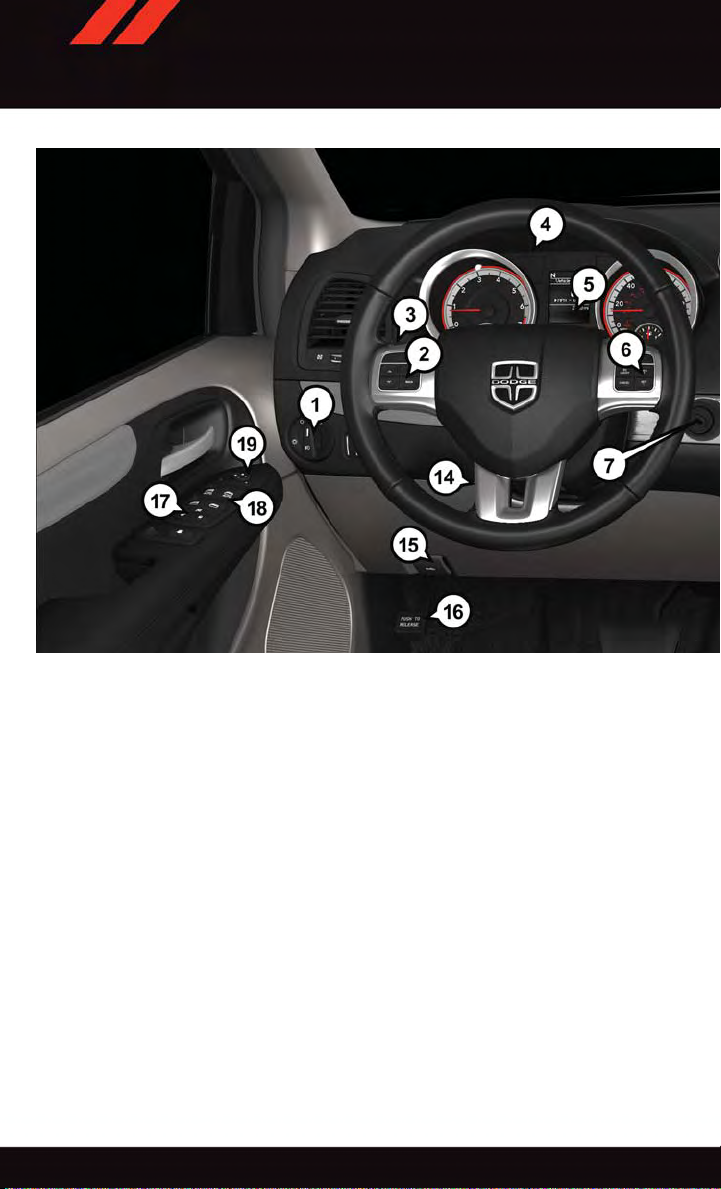
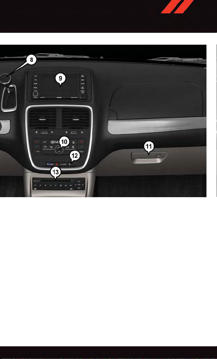
DRIVER COCKPIT
1. Headlight Switch pg. 30
2. Electronic Vehicle Information Center (EVIC) Controls pg. 67
3. Turn Signal/Wiper/Washer/High Beams Lever (behind steering wheel) pg. 28
4. Instrument Cluster pg. 6
5. Electronic Vehicle Information Center (EVIC) Display
6. Speed Control
7. Ignition
8. Shift Lever
9. Audio System (Touchscreen Radio Shown) pg. 36
10. Manual Climate Controls
4
Page 7
CONTROLS AT A GLANCE
11. Glove Compartment
12. Switch Panel
•ParkSense
•ECOOnpg.32
•ElectronicStabilityControl(ESC)OFFpg.78
13. DVD Player
14. Tilt/Telescoping Steering Column pg. 27
15. Hood Release pg. 103
16. Emergency Brake Pedal
17. Power Door Locks
18. Power Windows
19. Power Mirrors
®
pg. 35
5
Page 8
CONTROLS AT A GLANCE
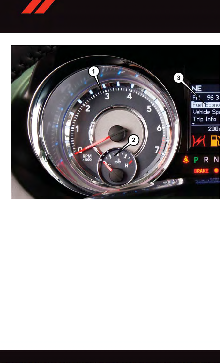
INSTRUMENT CLUSTER
1. Tachometer
2. Temperature Gauge
3. Electronic Vehicle Information Center (EVIC)
(See page 74 for more Instrument Cluster Warning Light information.)
6
Page 9
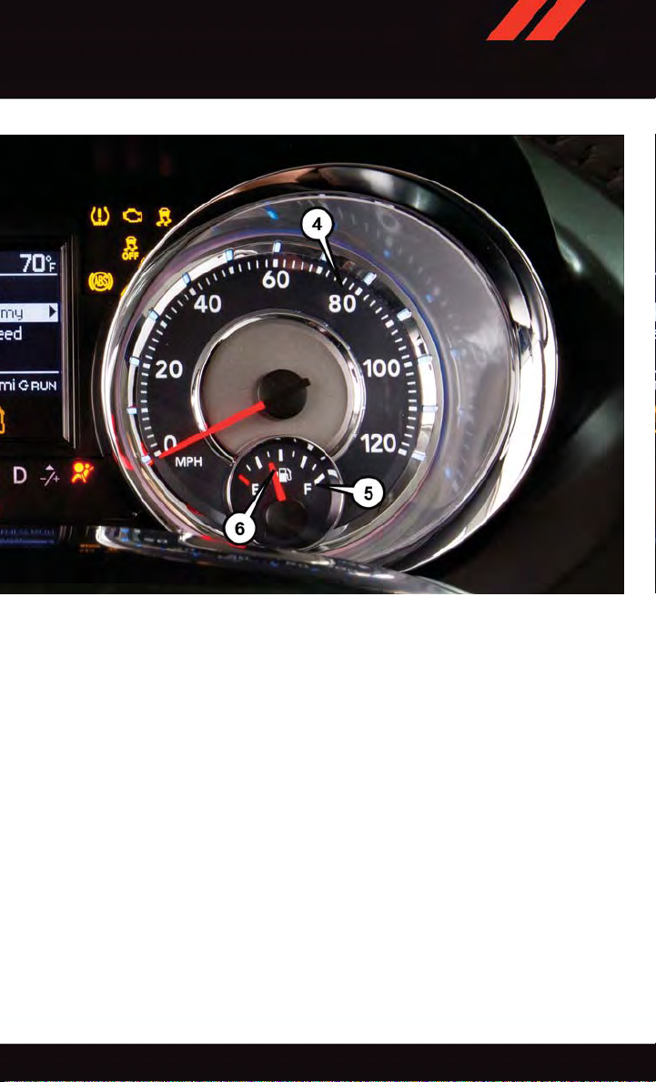
CONTROLS AT A GLANCE
4. Speedometer
5. Fuel Gauge
6. Fuel Filler Door Location
(See page 78 for more Instrument Cluster Indicator Light information.)
7
Page 10
GETTING STARTED
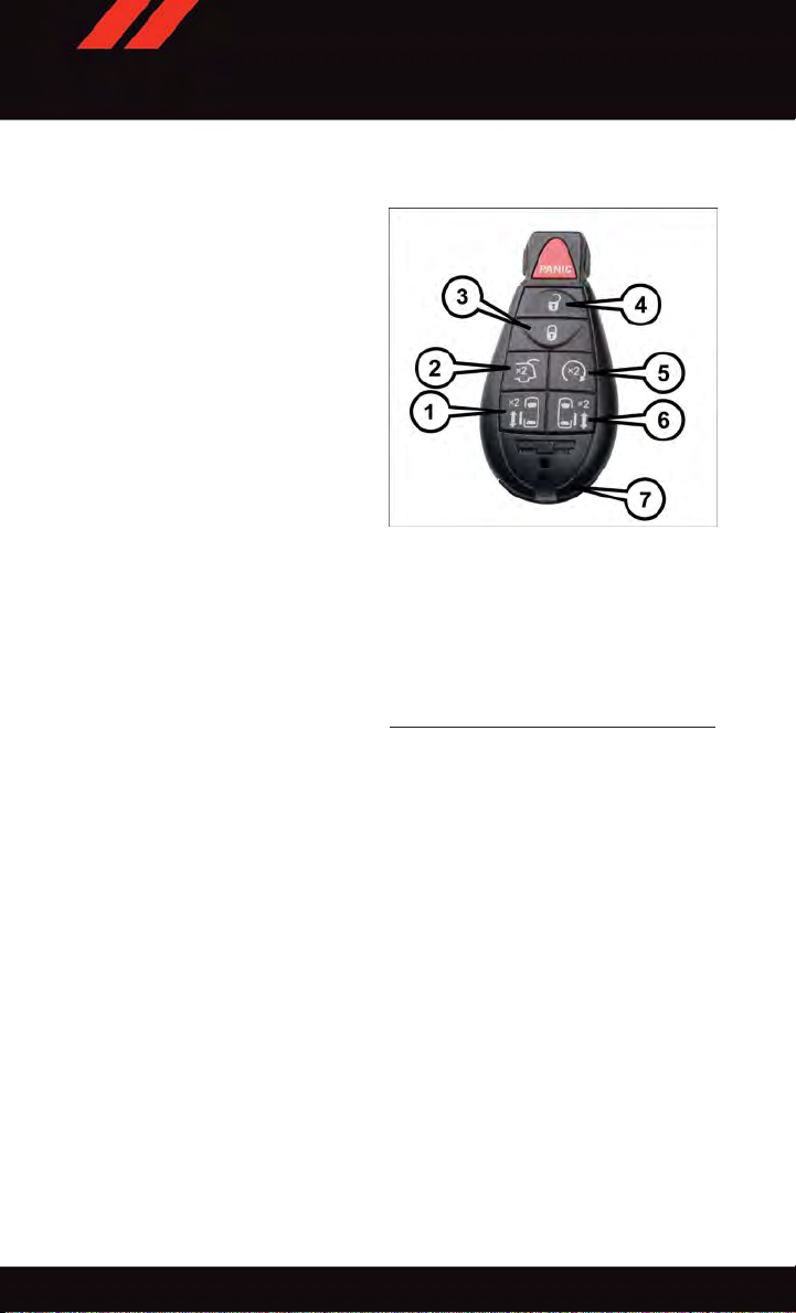
KEY FOB
Locking And Unlocking The Doors And Liftgate
Lock The Doors And Liftgate
•PushandreleasetheLOCKbuttonon
the RKE transmitter to lock all doors and
liftgate. The turn signal lights will flash,
and the horn will chirp to acknowledge
the signal.
Unlock The Doors And Liftgate
•PushandreleasetheUNLOCKbuttonon
the RKE transmitter once to unlock the
driver’s door or twice within five seconds
to unlock all doors and liftgate. The turn
signal lights will flash to acknowledge the
unlock signal. The illuminated entry system will also turn on.
All doors can be programmed to unlock on
the first push of the UNLOCK button. Refer
to “Programmable Features” in the “Electronics” section of this guide.
1—LeftPowerSlidingDoor
2—Liftgate
3—Lock
4—Unlock
5—RemoteStart
6—RightPowerSlidingDoor
7—EmergencyKey
Panic Alarm
1. Push the P ANIC button once to turn the panic alarm on.
2. Wait approximately three seconds and push the button a second time to turn the panic
alarm off.
Key Fob
Power Liftgate
•PushtheLIFTGATEbuttontwicewithinfivesecondstopoweropen/closethePower
Liftgate. If the button is pushed twice while the liftgate is being power closed, the
liftgate will reverse to the full open position.
Power Sliding Doors
•PushtheLEFTorRIGHTPowerSlidingDoorbuttontwicewithinfivesecondstopower
open/close the Power Sliding Door . If the button is pushed again while the door is being
power closed, the door will reverse to the full open position.
8
Page 11
GETTING STARTED
Emergency Key
Should the battery in the vehicle or the Key Fob transmitter go dead, there is an
emergency key located in the Key Fob that can be used for locking and unlocking the
doors.
•Toremovetheemergencykey,slidethebuttonatthetopoftheKeyFobsidewayswith
your thumb and then pull the key out with your other hand.
WARNING!
•Neverleavechildrenaloneinavehicle,orwithaccesstoanunlockedvehicle.
Allowing children to be in a vehicle unattended is dangerous for a number of
reasons. A child or others could be severely injured or killed. Children should be
warned not to touch the parking brake, brake pedal, or the transmission gear
selector. Do not leave the Key Fob in or near the vehicle, or in a location accessible
to children, and do not leave the ignition of a vehicle equipped with Keyless
Enter-N-Go™ in the ACC or ON/RUN mode. A child could start the vehicle, operate
power windows, other controls, or move the vehicle.
•Donotleavechildrenoranimalsinsideparkedvehiclesinhotweather.Interiorheat
build-up may cause them to be severely injured or killed.
•KeepKeyFobtransmittersawayfromchildren.OperationoftheRemoteStart
System, windows, door locks or other controls could cause serious injury or death.
REMOTE START
x
•PushtheREMOTESTARTbutton
Pushing the REMOTE ST AR T button a third time shuts the engine off.
•Todrivethevehicle,pushtheUNLOCKbutton,inserttheKeyFobintheignitionand
turn to the ON/RUN position.
•Withremotestart,theenginewillonlyrunfor15minutes(timeout)unlesstheignition
Key Fob is placed in the ON/RUN position.
•ThevehiclemustbestartedwiththeKeyFobaftertwoconsecutivetimeouts.
2
on the Key Fob twice within five seconds.
WARNING!
•Donotstartorrunanengineinaclosedgarageorconfinedarea.Exhaustgas
contains Carbon Monoxide (CO) which is odorless and colorless. Carbon Monoxide
is poisonous and can cause you or others to be severely injured or killed when
inhaled.
•KeepKeyFobtransmittersawayfromchildren.OperationoftheRemoteStart
System, windows, door locks or other controls could cause you and others to be
severely injured or killed.
9
Page 12
GETTING STARTED
KEYLESS ENTER-N-GO™
The Keyless Enter-N-Go™ system is an enhancement to the vehicle’ s Remote Keyless
Entry (RKE) feature. This feature allows you to lock and unlock the vehicle's door(s) and
liftgate without having to push the Key Fob lock or unlock buttons, as well as starting and
stopping the vehicle with the push of a button.
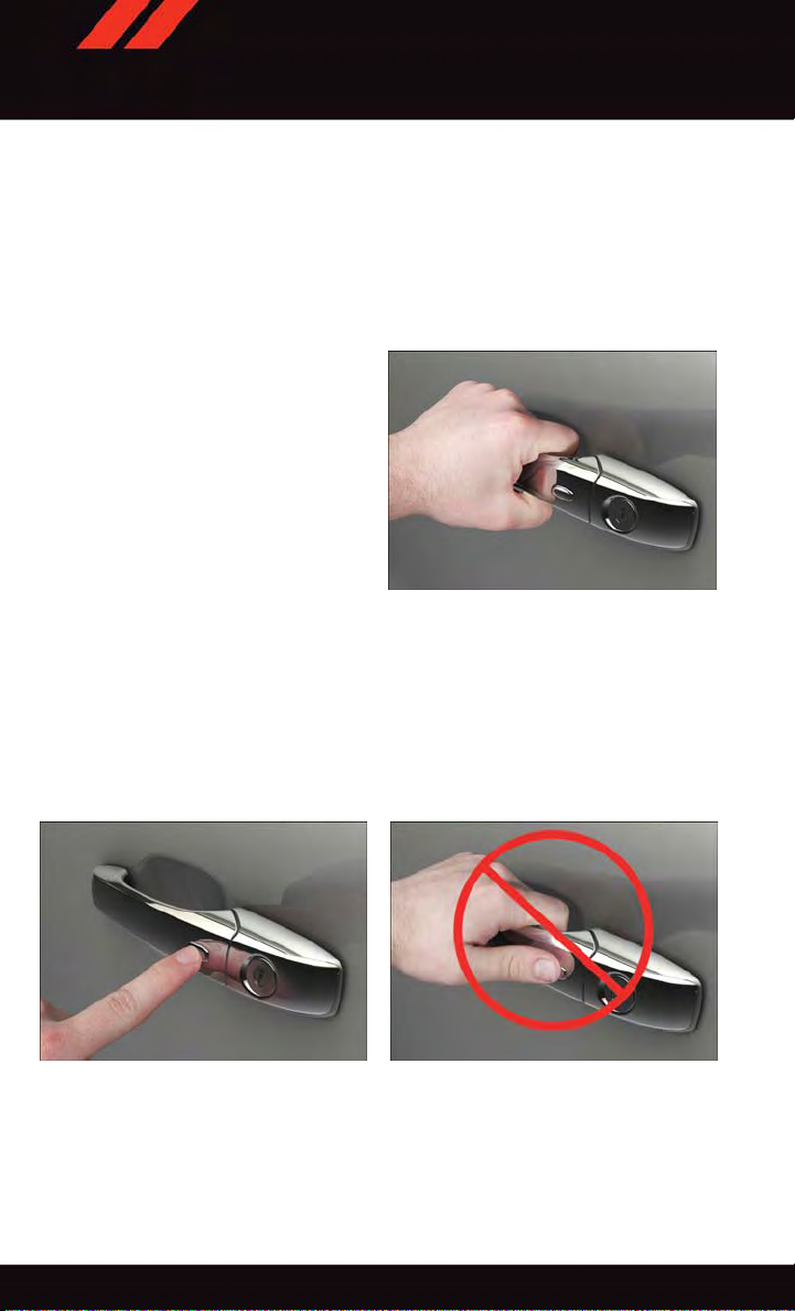
To Unlock From The Driver or Passenger Side:
•
With a valid Keyless Enter-N-Go™ Key
Fob located outside the vehicle and within
5ft(1.5m)ofthedriverorpassengerside
door handle, grab either front door handle
to unlock the door automatically.
Grab The Door Handle To Unlock
To Lock The Vehicle
•Bothfrontdoorhandleshavebuttonslocatedontheoutsideofthehandle.Withoneof
the vehicles Keyless Enter-N-Go™ Key Fobs located outside the vehicle and within 5 ft
(1.5m) of the driver's or passenger front door handle, push the door handle button to
lock all four doors and liftgate.
•DONOTgrabthedoorhandle,whenpushingthedoorhandlebutton.Thiscouldunlock
the door(s).
Push The Door Handle Button To Lock Do Not Grab The Door Handle
NOTE:
If “Unlock All Doors 1st Press” is programmed, all doors will unlock when you grab hold of
•
the front driver's door handle. T o select between “Unlock Driver Door 1st Press” and “Unlock
All Doors 1st Press,” refer to the “Electronic Vehicle Information Center (EVIC)” in your
vehicles Owner's Manual on the DVD or “Programmable Features” in this guide for further
information.
10
Page 13

GETTING STARTED
•If“UnlockAllDoors1stPress”isprogrammed,alldoorsandliftgatewillunlockwhen
you push the liftgate button. If “Unlock Driver Door 1st Press” is programmed, only the
liftgate will unlock when you push the liftgate button. T o select between “Unlock Driver
Door 1st Press” and “Unlock All Doors 1st Press,” refer to the “Electronic Vehicle
Information Center (EVIC)” in your vehicles Owner's Manual on the DVD or “Programmable Features” in this guide for further information.
•IfaKeyFobisdetectedinthevehiclewhenlockingthevehicleusingthepowerdoor
lock switch, the doors and liftgate will unlock, and the horn will chirp three times. On
the third attempt, your Key Fob can be locked inside the vehicle.
•AfterpushingtheKeylessEnter-N-Go™LOCKbutton,youmustwaittwoseconds
before you can lock or unlock the vehicle using the door handle. This is done to allow
you to check if the vehicle is locked by pulling the door handle without the vehicle
reacting and unlocking.
•IfaKeylessEnter-N-Go™doorhandlehasnotbeenusedfor72hours,theKeyless
Enter-N-Go™ feature for that handle may time out. Pulling the deactivated front door
handle will reactivate the door handle's Keyless Enter-N-Go™ feature.
Lock Or Unlock The Liftgate:
•WithavalidPassiveEntryRKEtransmitterwithin5ft(1.5m)oftheliftgate,cyclethe
handle to open the liftgate and pull the liftgate open with one fluid motion.
NOTE:
•Alldoorswillremainlockedwhentheliftgatereleasehandleispushedregardlessofthe
driver’s door unlock preference setting (“Unlock Driver Door 1st Press” or “Unlock All
Doors 1st Press”).
•RefertoyourOwner'sManualontheDVDforfurtherinformation.
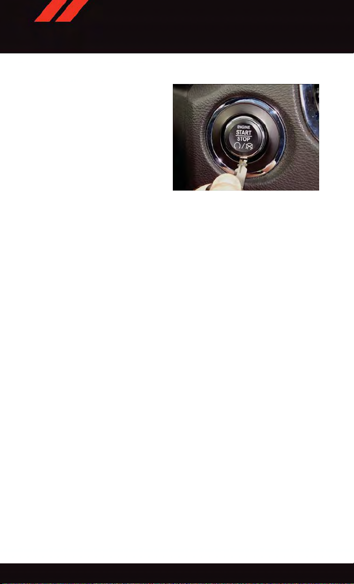
Installing And Removing The ENGINE START/STOP Button
Installing The Button
•RemovetheKeyFobfromtheignitionswitch.
•InserttheENGINESTART/STOPbuttonintotheignitionswitchwiththelettering
facing up and readable.
•Pushfirmlyonthecenterofthebuttontosecureitintoposition.
11
Page 14
GETTING STARTED
Removing The Button
•TheENGINESTART/STOPbuttoncan
be removed from the ignition switch for
Key Fob use.
•Insertthemetalpartoftheemergency
key under the chrome bezel at the 6
o’clock position and gently pry the button
loose.
NOTE:
The ENGINE START/STOP button should
only be removed or inserted with the ignition in the LOCK position (OFF position for
Keyless Enter-N-Go™).
Engine Starting/Stopping
Starting
Perform the following starting procedure with a Remote Keyless Entry (RKE) transmitter
inside the vehicle:
1. Place the shift lever in PARK or NEUTRAL.
2. While pushing the brake pedal, push the ENGINE STAR T/STOP button once. If the
engine fails to start, the starter will disengage automatically after 10 seconds.
3. To stop the cranking of the engine prior to the engine starting, push the button again.
Stopping
1. Bring the vehicle to a complete stop.
2. Shift the transmission to PARK (P).
3. Push the ENGINE STAR T/STOP button once. The ignition switch will return to the OFF
position.
NOTE:
If the transmission is not in PARK and the vehicle is in motion, the ENGINE START/STOP
button must be held for two seconds with the vehicle speed above 5 mph (8 km/h) before
the engine will shut off.
Removing START/STOP Button
Accessory Positions With Engine Off
NOTE:
The following functions are with the driver’s foot off of the Brake Pedal (transmission in
PARK o r NEU TRAL).
12
Page 15
GETTING STARTED
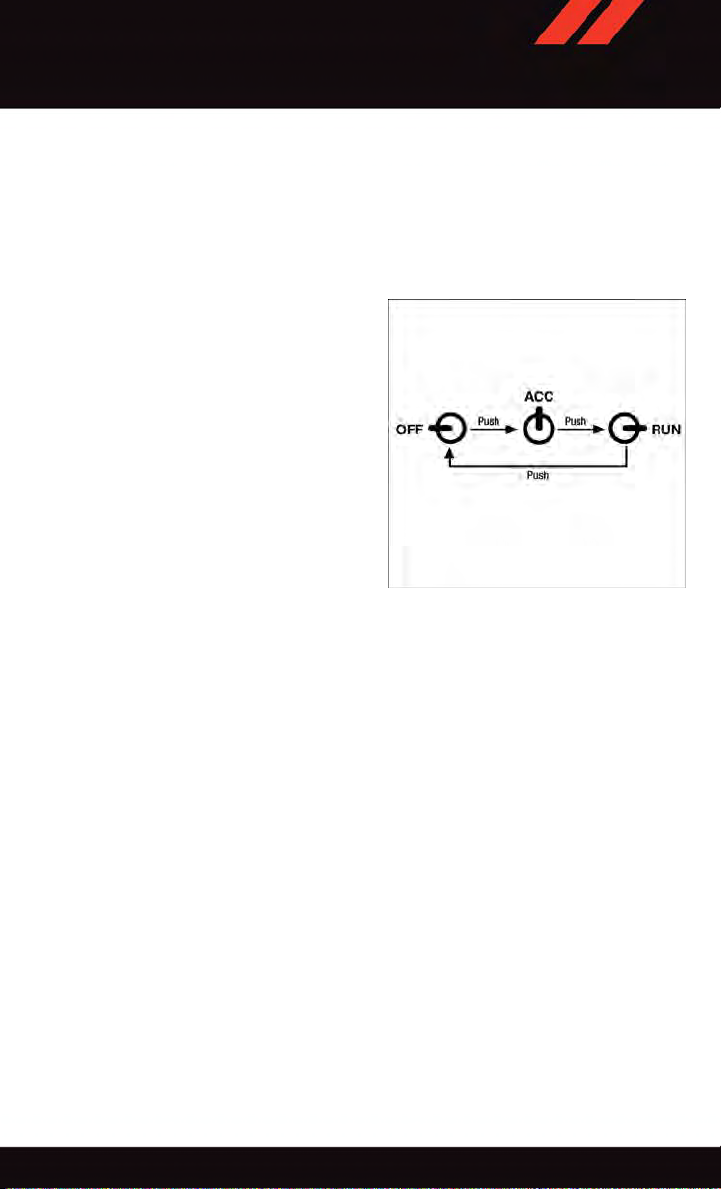
Beginning With The Ignition Switch In The OFF Position:
1. Push the ENGINE STAR T/STOP button once to cycle the ignition to the ACC position.
2. Push the ENGINE START/STOP button a second time to cycle the ignition to the
ON/RUN position.
3. Push the ENGINE START/STOP button a third time to return the ignition to the OFF
position.
NOTE:
If the ignition is left in the ACC or ON/RUN
(engine not running) position and the transmission is in PARK, the system will automatically time out after 30 minutes of inactivity, and the ignition is returned to the OFF
position.
Ignition Positions
VEHICLE SECURITY ALARM
The Vehicle Security Alarm monitors the vehicle doors for unauthorized entry and the
Keyless Enter-N-Go™ START/STOP button for unauthorized operation. While the Vehicle
Security Alarm is armed, interior switches for door locks and decklid release are disabled.
If something triggers the alarm, the Vehicle Security Alarm will provide the following
audible and visible signals: the horn will pulse, the park lamps and/or turn signals will
flash, and the Vehicle Security Light in the instrument cluster will flash.
To Arm:
Lock the door using either the power door lock switch (one door must be open) or the
LOCK button on the Remote Keyless Entry (RKE) transmitter (doors can be open or
closed), and close all doors.
The Vehicle Security Light in the instrument cluster will flash for 16 seconds. This shows
that the Vehicle Security Alarm is arming. During this period, if a door is opened, the
ignition is cycled to ON/RUN, or the power door locks are unlocked in any manner, the
Vehicle Security Alarm will automatically disarm.
NOTE:
•TheVehicleSecurityAlarmwillnotarmifyoulockthedoorswiththemanualdoorlock
plungers.
•Oncearmed,theVehicleSecurityAlarmdisablestheunlockswitchonthedriverdoor
trim panel and passenger door trim panel.
13
Page 16

GETTING STARTED
To Disarm The System:
Push the Key Fob UNLOCK button or cycle the ignition to the ON/RUN position.
The Vehicle Security Alarm is designed to protect your vehicle. However , you can create
conditions where the Vehicle Security Alarm will give you a false alarm. If one of the
previously described arming sequences has occurred, the Vehicle Security Alarm will arm
regardless of whether you are in the vehicle or not. If you remain in the vehicle and open
adoor,thealarmwillsound.Ifthisoccurs,disarmtheVehicleSecurityAlarm.
If the Vehicle Security Alarm is armed and the battery becomes disconnected, the Vehicle
Security Alarm will remain armed when the battery is reconnected. The exterior lights will
flash, and the horn will sound. If this occurs, disarm the Vehicle Security Alarm.
SEAT BELT SYSTEMS
Lap/Shoulder Belts
•Allseatingpositionsinyourvehicleareequippedwithlap/shoulderbelts.
•Besureeveryoneinyourvehicleisinaseatandusingaseatbeltproperly.
•Positionthelapbeltsothatitissnugandlieslowacrossyourhips,belowyour
abdomen. To remove slack in the lap belt portion, pull up on the shoulder belt. To loosen
the lap belt if it is too tight, tilt the latch plate and pull on the lap belt. A snug seat belt
reduces the risk of sliding under the seat belt in a collision.
•Positiontheshoulderbeltacrosstheshoulderandchestwithminimal,ifanyslackso
that it is comfortable and not resting on your neck. The retractor will withdraw any slack
in the shoulder belt.
Seat Belt Pretensioner
•Thefrontseatbeltsystemisequippedwithpretensioningdevicesthataredesignedto
remove slack from the seat belt in the event of a collision.
•Adeployedpretensioneroradeployedairbagmustbereplacedimmediately.
WARNING!
•Inacollision,youandyourpassengerscansuffermuchgreaterinjuriesifyouare
not properly buckled up. You can strike the interior of your vehicle or other
passengers, or you can be thrown out of the vehicle. Always be sure you and others
in your vehicle are buckled up properly.
•Ashoulderbeltplacedbehindyouwillnotprotectyoufrominjuryduringacollision.
You ar e mor e lik ely t o hit your head in a co llision if you do no t wea r you r sho ulder
belt. The lap and shoulder belt are meant to be used together.
•Aseatbeltthatistooloosewillnotprotectyouproperly.Inasuddenstop,youcould
move too far forward, increasing the possibility of injury. Wear your seat belt snugly.
•Afrayedortornseatbeltcouldripapartinacollisionandleaveyouwithno
protection. Inspect the seat belt system periodically, checking for cuts, frays, or
loose parts. Damaged parts must be replaced immediately. Do not disassemble or
modify the system. Seat belt assemblies must be replaced after a collision.
14
Page 17

GETTING STARTED
SUPPLEMENTAL RESTRAINT SYSTEM (SRS) — AIR BAGS
Air Bag System Components
Your v ehicle may be e quipped with the follo wing air bag system compo nents:
•OccupantRestraintController(ORC)
•AirBagWarningLight
•SteeringWheelandColumn
•InstrumentPanel
•KneeImpactBolsters
•AdvancedFrontAirBags
•SupplementalSideAirBags
•SupplementalKneeAirBags
•FrontandSideImpactSensors
•SeatBeltPretenioners
•SeatBeltBuckleSwitch
•SeatTrackPositionSensors
Advanced Front Air Bags
•ThisvehiclehasAdvancedFrontAirBagsforboththedriverandfrontpassengerasa
supplement to the seat belt restraint systems. The Advanced Front Air Bags will not
deploy in every type of collision.
•AdvancedFrontAirBagsaredesignedtoprovideadditionalprotectionbysupplementing the seat belts. Advanced Front Air Bags are not expected to reduce the risk of injury
in rear, side, or rollover collisions.
•TheAdvancedFrontAirBagswillnotdeployinallfrontalcollisions,includingsome
that may produce substantial vehicle damage — for example, some pole collisions,
truck underrides, and angle offset collisions.
•Ontheotherhand,dependingonthetypeandlocationofimpact,AdvancedFrontAir
Bags may deploy in crashes with little vehicle front-end damage but that produce a
severe initial deceleration.
•Becauseairbagsensorsmeasurevehicledecelerationovertime,vehiclespeedand
damage by themselves are not good indicators of whether or not an air bag should have
deployed.
•Seatbeltsarenecessaryforyourprotectioninallcollisions,andalsoareneededtohelp
keep you in position, away from an inflating air bag.
•Theairbagsmustbereadytoinflateforyourprotectioninacollision.TheOccupant
Restraint Controller (ORC) monitors the internal circuits and interconnecting wiring
associated with air bag system electrical components.
15
Page 18

GETTING STARTED
•TheORCturnsontheAirBagWarningLightintheinstrumentpanelforapproximately
four to eight seconds for a self-check when the ignition switch is first turned to the
ON/RUN position. After the self-check, the Air Bag Warning Light will turn off. If the
ORC detects a malfunction in any part of the system, it turns on the Air Bag Warning
Light, either momentarily or continuously. A single chime will sound to alert you if the
light comes on again after initial startup.
•TheORCmonitorsthereadinessoftheelectronicpartsoftheairbagsystemwhenever
the ignition switch is in the START or ON/RUN position. If the ignition switch is in the
OFF position or in the ACC position, the air bag system is not on and the air bags will
not inflate.
•IftheAirBagWarningLightintheinstrumentpanelisnotonduringthefourtoeight
seconds when the ignition switch is first turned to the ON/RUN position, stays on, or
turns on while driving, have the vehicle serviced by an authorized service center
immediately.
NOTE:
If the speedometer, tachometer, or any engine related gauges are not working, the
Occupant Restraint Controller (ORC) may also be disabled. In this condition the air bags
may not be ready to inflate for your protection. Have an authorized dealer service the air
bag system immediately.
•Afteranycollision,thevehicleshouldbetakentoanauthorizeddealerimmediately.
•Donotdriveyourvehicleaftertheairbagshavedeployed.Ifyouareinvolvedinanother
collision, the air bags will not be in place to protect you.
•Ifitisnecessarytomodifytheairbagsystemforpersonswithdisabilities,contactyour
authorized dealer.
•RefertotheOwner'sManualontheDVDforfurtherdetailsregardingtheSupplemental
Restraint System (SRS).
Supplemental Knee Air Bags
This vehicle is equipped with a Supplemental Driver Knee Air Bag mounted in the
instrument panel below the steering column. The Supplemental Driver Knee Air Bag
provides enhanced protection during a frontal impact by working together with the seat
belts, pretensioners, and Advanced Front Air Bags.
WARNING!
•Relyingontheairbagsalonecouldleadtomoresevereinjuriesinacollision.The
air bags work with your seat belt to restrain you properly. In some collisions, the air
bags won't deploy at all. Always wear your seat belts even though you have air bags.
•BeingtooclosetothesteeringwheelorinstrumentpanelduringAdvancedFrontAir
Bag deployment could cause serious injury, including death. Air bags need room to
inflate. Sit back, comfortably extending your arms to reach the steering wheel or
instrument panel.
•Noobjectsshouldbeplacedoverorneartheairbagontheinstrumentpanelor
steering wheel because any such objects could cause harm if the vehicle is in a
collision severe enough to cause the air bag to inflate.
16
Page 19
GETTING STARTED
Supplemental Side Air Bags
•ThisvehicleisequippedwithSupplementalSeat-MountedSideAirBags(SABs)
located in the outboard side of the front seats. The SABs are marked with a SRS
AIRBAG or AIRBAG label sewn into the outboard side of the seats.
•ThisvehicleisequippedwithSupplementalSideAirBagInflatableCurtains(SABICs)
located above the side windows. The trim covering the SABICs is labeled SRS AIRBAG
or AIRBAG. The SABICs may help reduce the risk of partial or complete ejection of
vehicle occupants through side windows in certain side impact events.
•TheSABICsandSABs(“SideAirBags”)aredesignedtoactivateincertainside
impacts and certain rollover events. The Occupant Restraint Controller (“ORC”)
determines whether the deployment of the Side Air Bags in a particular side impact or
rollover event is appropriate, based on the severity and type of collision. Vehicle damage
by itself is not a good indicator of whether or not Side Air Bags should have deployed.
WARNING!
•SideAirBagsneedroomtoinflate.Donotleanagainstthedoororwindow.Sit
upright in the center of the seat.
•BeingtooclosetotheSideAirBagsduringdeploymentcouldcauseyoutobe
severely injured or killed.
•RelyingontheSideAirBagsalonecouldleadtomoresevereinjuriesinacollision.
The Side Air Bags work with your seat belt to restrain you properly. In some
collisions, Side Air Bags won’t deploy at all. Always wear your seat belt even though
you have Side Air Bags.
•ThisvehicleisequippedwithleftandrightSupplementalSideAirBagInflatable
Curtains (SABICs). Do not stack luggage or other cargo up high enough to block the
deployment of the SABICs. The trim covering above the side windows where the
SABIC and its deployment path are located should remain free from any obstructions.
•ThisvehicleisequippedwithSABICs.InorderfortheSABICstoworkasintended,
do not install any accessory items in your vehicle which could alter the roof. Do not
add an aftermarket sunroof to your vehicle. Do not add roof racks that require
permanent attachments (bolts or screws) for installation on the vehicle roof. Do not
drill into the roof of the vehicle for any reason.
•DonotuseaccessoryseatcoversorplaceobjectsbetweenyouandtheSideAir
Bags; the performance could be adversely affected and/or objects could be pushed
into you, causing serious injury.
17
Page 20
GETTING STARTED
CHILD RESTRAINTS
Children 12 years or younger should ride properly buckled up in a rear seat, if available.
According to crash statistics, children are safer when properly restrained in the rear seats
rather than in the front.
Every state in the United States and all Canadian provinces require that small children
ride in proper restraint systems. This is the law, and you can be prosecuted for ignoring it.
NOTE:
•Foradditionalinformation,refertowww.Seatcheck.orgorcall1-866-SEATCHECK.
•CanadianresidentsshouldrefertoTransportCanada’swebsiteforadditionalinformation: http://www.tc.gc.ca/eng/motorvehiclesafety/safedrivers-childsafety-index-53.htm
LATCH – Lower Anchors And Tethers For CHildren
•YourvehicleisequippedwiththechildrestraintanchoragesystemcalledLATCH,
which stands for Lower Anchors and Tethers for CHildren.
•Thesecondrowseatingpostionsandthethirdrowcenterpositionhaveloweranchors
and top tether anchors.
LATCH System Weight Limit
You may use the LATCH anchorage sys tem un til the co mbined weig ht of the child and the
child restraint is 65 lbs (29.5 kg). Use the seat belt and tether anchor instead of the
LA TCH system once the combined weight is more than 65 lbs (29.5 kg).
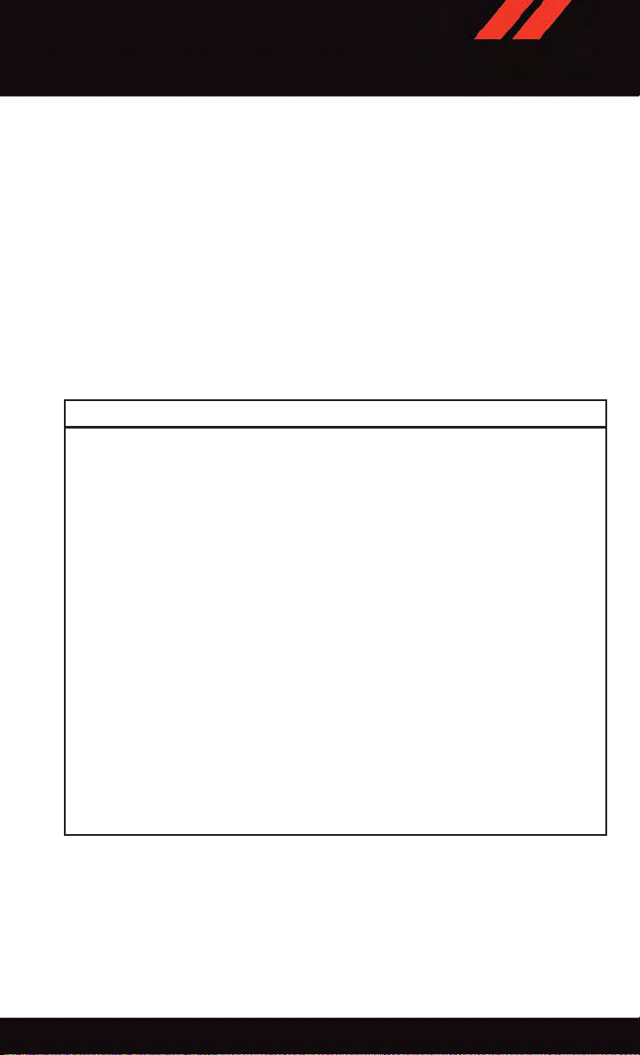
Locating LATCH Anchorages
The lower anchorages are round bars that are found at the rear of the seat cushion
where it meets the seatback. They are just visible when you lean into the rear seat to install
the child restraint. You will easily feel them if you run your finger along the gap between
the seatback and seat cushion.
Lower Anchorages
18
Page 21
GETTING STARTED
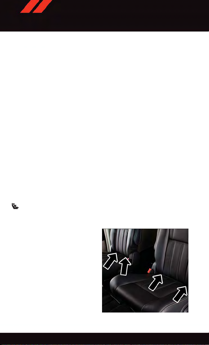
Locating Tether Anchorages
In addition, there are tether strap anchors located behind each rear seatback, near
to the floor.
Center Seat LATCH
If a child restraint installed in the center
position blocks the seat belt webbing or
buckle for the outboard position, do not use
that outboard position. If a child seat in the
center position blocks the outboard LATCH
anchors or seat belt, do not install a child
seat in that outboard position.
Installing The Child Restraint Using
The LATCH Lower Anchors
NOTE:
Never “share” a LATCH anchorage with two
or more child restraints.
1. Loosen the adjusters on the lower straps and on the tether strap of the child seat so that
you can more easily attach the hooks or connectors to the vehicle anchorages.
2. Attach the lower hooks or connectors of the child restraint to the lower anchorages in
the selected seating position.
3. If the child restraint has a tether strap, connect it to the top tether anchorage. See
below for directions to attach a tether anchor .
4. Tighten all of the straps as you push the child restraint rearward and downward into the
seat. Remove slack in the straps according to the child restraint manufacturer’s
instructions.
5. Test that the child restraint is installed tightly by pulling back and forth on the child
seat at the belt path. It should not move more than 1 inch (25.4 mm) in any direction.
Tether Anchorages
Installing The Child Restraint Using The Vehicle Seat Belts
Except for the center position in the third row, all of the seat belts in the passenger seating
positions are equipped with a Switchable Automatic Locking Retractor (ALR). The third
row center position is equipped with a cinching latch plate. Both types of seat belts are
designed to keep the lap portion of the seat belt tight around the child restraint. Any seat
belt system will loosen with time, so check the belt occasionally, and pull it tight if
necessary.
Tether Anchorage Weight Limit
Always use the tether anchor when using the seat belt to install a forward facing child
restraint, up to the recommended weight limit of the child restraint.
19
Page 22

GETTING STARTED
To Install A Child Seat Using An ALR:
1. Pull enough of the seat belt webbing from the retractor to pass it through the belt path
of the child restraint. Do not twist the belt webbing in the belt path.
2. Slide the latch plate into the buckle until you hear a “click.”
3. Pull on the webbing to make the lap portion tight against the child seat.
4. To lock the seat belt, pull down on the shoulder part of the belt until you have pulled
all the seat belt webbing out of the retractor. Then, allow the webbing to retract back
into the retractor. As the webbing retracts, you will hear a clicking sound. This means
the seat belt is now in the Automatic Locking mode.
5. Try to pull the webbing out of the retractor. If it is locked, you should not be able to pull
out any webbing. If the retractor is not locked, repeat the last step.
6. Finally, pull up on any extra webbing to tighten the lap portion around the child
restraint while you push the child restraint rearward and downward into the vehicle
seat.
7. If the child restraint has a top tether strap and the seating position has a top tether
anchorage, connect the tether strap to the anchorage and tighten the tether strap. See
below for directions to attach a tether anchor .
8. Test that the child restraint is installed tightly by pulling back and forth on the child
seat at the belt path. It should not move more than 1 inch (25.4 mm) in any direction.
To Install A Child Seat Using A Cinching Latch Plate:
1. Place the child seat in the center of the seating position.
2. Next, pull enough of the seat belt webbing from the retractor to pass it through the belt
path of the child restraint. Do not twist the belt webbing in the belt path.
3. Slide the latch plate into the buckle until you hear a “click.”
4. Finally, pull up on any excess webbing to tighten the lap portion around the child
restraint while you push the child restraint rearward and downward into the vehicle
seat.
5. If the child restraint has a top tether strap and the seating position has a top tether
anchorage, connect the tether strap to the anchorage and tighten the tether strap. See
below for directions to attach a tether anchor .
6. Test that the child restraint is installed tightly by pulling back and forth on the child
seat at the belt path. It should not move more than 1 inch (25.4 mm) in any direction.
Installing The Top Tether Strap (With Either Lower Anchors Or Vehicle Seat Belt):
When installing a forward-facing child restraint, always secure the top tether strap, up to
the tether anchor weight limit, whether the child restraint is installed with the lower
anchors or the vehicle seat belt.
20
Page 23
GETTING STARTED
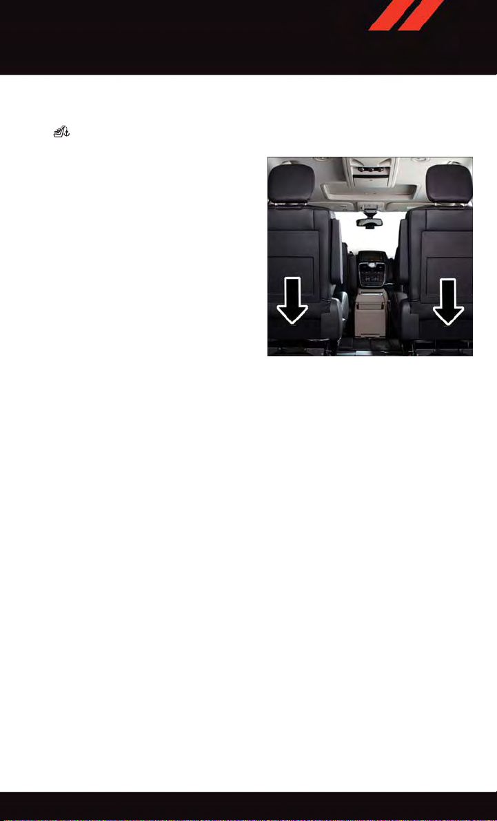
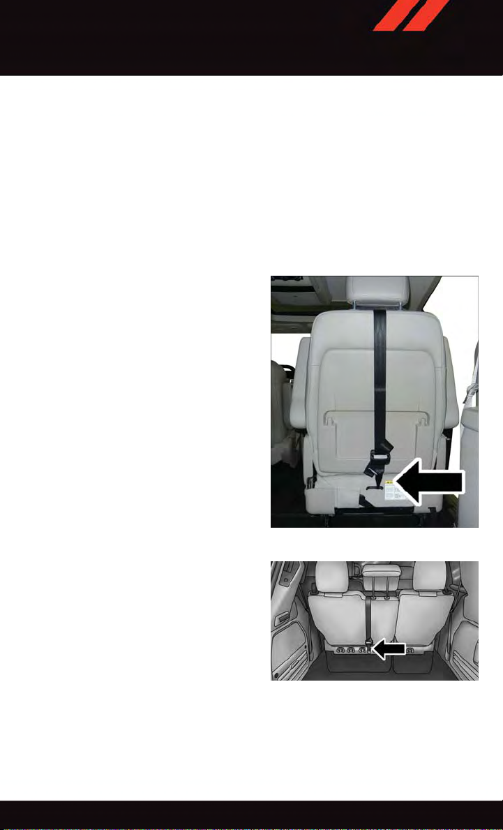
Tether Anchorage Installation
1. Route the tether strap to provide the most direct path for the strap between the anchor
and the child seat.
2. If your vehicle is equipped with adjustable rear head restraints, raise the head
restraint, and where possible, route the tether strap under the head restraint and
between the two posts. If not possible, lower the head restraint and pass the tether
strap around the outboard side of the head restraint.
3. Attach the tether strap hook of the child restraint to the top tether anchorage and
remove slack in the tether strap according to the child restraint manufacturer’s
instructions.
Rear Seat Tether Strap Mounting (Second
Row Anchorage Shown)
Top Tether Strap Mounting (Third Row 60/40
Anchorage Shown)
21
Page 24
GETTING STARTED
WARNING!
Securely lock the seat cushion into position before using the seat. Otherwise, the seat
will not provide the proper stability for child seats and/or passengers. An improperly
latched seat cushion could cause serious injury.
WARNING!
•Inacollision,anunrestrainedchild,evenatinybaby,canbecomeaprojectile
inside the vehicle. The force required to hold even an infant on your lap could
become so great that you could not hold the child, no matter how strong you are.
The child and others could be severely injured or killed. Any child riding in your
vehicle should be in a proper restraint for the child's size.
•Rearward-facingchildseatsmustneverbeusedinthefrontseatofavehiclewith
afrontpassengerairbag.Anairbagdeploymentcouldcausesevereinjuryordeath
to infants in this position.
•Onlyusearearward-facingchildrestraintinavehiclewitharearseat.
•ImproperinstallationofachildrestrainttotheLATCHanchoragescanleadto
failure of an infant or child restraint. The child could be severely injured or killed.
Follow the manufacturer’s directions exactly when installing an infant or child
restraint.
•Anincorrectlyanchoredtetherstrapcouldleadtoincreasedheadmotionand
possible injury to the child. Use only the anchor positions directly behind the child
seat to secure a child restraint top tether strap.
•Ifyourvehicleisequippedwithasplitrearseat,makesurethetetherstrapdoesnot
slip into the opening between the seatbacks as you remove slack in the strap.
HEAD RESTRAINTS
Head restraints are designed to reduce the risk of injury by restricting head movement in
the event of a rear impact. Head restraints should be adjusted so that the top of the head
restraint is located above the top of your ear.
WARNING!
The head restraints for all occupants must be properly installed and adjusted prior to
operating the vehicle or occupying a seat. Head restraints should never be adjusted
while the vehicle is in motion. Driving a vehicle with the head restraints improperly
adjusted or removed could cause serious injury or death in the event of a collision.
Active Head Restraints — Front Seats
Active Head Restraints are passive, deployable components, and vehicles with this
equipment cannot be readily identified by any markings, only through visual inspection of
the head restraint. The Active Head Restraints (AHR) will be split in two halves, with the
front half being soft foam and trim, the back half being decorative plastic.
22
Page 25
GETTING STARTED
When AHRs deploy during a rear impact, the front half of the head restraint extends
forward to minimize the gap between the back of the occupant’s head and the AHR. This
system is designed to help prevent or reduce the extent of injuries to the driver and front
passenger in certain types of rear impacts. Refer to “Occupant Restraints” in your Owner’s
Manual on the DVD for further information.
To ra ise t he h ead res t rai nt, p ull upw a rd o n th e he a d re str a int . To l owe r the hea d re s tra i nt,
press the push button, located at the base of the head restraint, and push downward on
the head restraint.
For comfort the Active Head Restraints can be tilted forward and rearward. To tilt the head
restraint closer to the back of your head, pull forward on the bottom of the head restraint.
Push rearward on the bottom of the head restraint to move the head restraint away from
your head.
NOTE:
•
The head restraints should only be removed by qualified technicians, for service purposes
only. If either of the head restraints require removal, see your authorized dealer.
•IntheeventofdeploymentofanActiveHeadRestraint,referto“OccupantRestraints”
in your Owner’s Manual on the DVD for further information.
WARNING!
•DonotplaceitemsoverthetopoftheActiveHeadRestraint,suchascoats,seat
covers or portable DVD players. These items may interfere with the operation of the
Active Head Restraint in the event of a collision and could result in serious injury or
death.
•ActiveHeadRestraintsmaybedeployediftheyarestruckbyanobjectsuchasa
hand, foot or loose cargo. To avoid accidental deployment of the Active Head
Restraint ensure that all cargo is secured, as loose cargo could contact the Active
Head Restraint during sudden stops. Failure to follow this warning could cause
personal injury if the Active Head Restraint is deployed.
Head Restraints — Second Row Quad Seats
To ra ise t he h ead res t rai nt, p ull upw a rd o n th e he a d re str a int . To l owe r the hea d re s tra i nt,
press the push button, located at the base of the head restraint, and push downward on
the head restraint.
Head Restraints — Second Row Bench
If your vehicle is equipped with a second row bench seat, the head restraints are not
adjustable.
Head Restraints — Third Row
The head restraint in the center position can be raised and lowered for tether routing. Refer to
“Occupant Restraints” in your Owner’s Manual on the DVD for further information.
23
Page 26
GETTING STARTED
FRONT SEATS
Power Seat
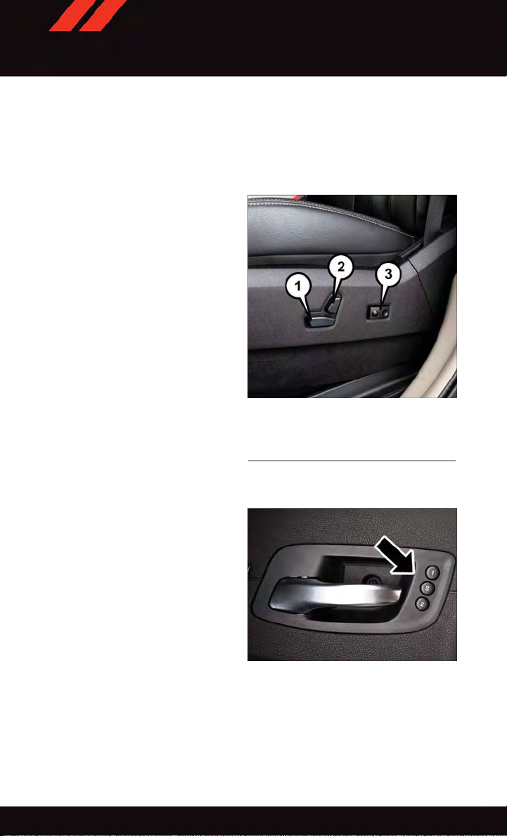
The power seat switch controls forward/back, up/down, and tilt adjustment.
The recline switch, located on the outboard side of the seat, controls seatback adjustment.
Power Lumbar
•Pushtheswitchforwardtoincreasethe
lumbar support. Push the switch rearward to decrease the lumbar support.
1—LowerSeatSwitch
2—ReclineSwitch
3—PowerLumbarSwitch
Power Seat Switches
Memory Seat
The memory seat feature allows you to save
two different driver seating positions, driver's outside mirror, adjustable brake and
accelerator pedals, and radio station preset
settings. The memory seat buttons are located on the driver's door panel.
To set a m emo r y pos iti o n:
1. Cycle the vehicles ignition to the ON
position.
2. Adjust all memory profile settings.
3. Press and release the S (SET) button.
4. Press and release the 1 or 2 button
within five seconds.
NOTE:
Before programming your RKE transmitters you must select the select “RKE Linked to
Memory” in the Electronic Vehicle Information Center (EVIC). Refer to “Programmable
Features” in “Electronics” for further information.
Memory Seat Button Location
24
Page 27
GETTING STARTED
To pro gra m a K ey Fo b to th e m emo ry po s iti on:
1. Cycle the vehicles ignition to the OFF position.
2. Select the desired memory profile 1 or 2.
3. Press and release the S (SET) button on the memory switch, then within five seconds
press and release the 1 or 2 button accordingly.
4. Press and release the LOCK button on the RKE transmitter within 10 seconds.
•Torecallthesavedpositions,press1or2onthememoryswitchorpressUNLOCKon
the programmed RKE transmitter .
CAUTION!
Do not place any article under a power seat or impede its ability to move as it may cause
damage to the seat controls. Seat travel may become limited if movement is stopped
by an obstruction in the seat’s path.
WARNING!
•Adjustingaseatwhilethevehicleismovingisdangerous.Thesuddenmovementof
the seat could cause you to lose control. The seat belt might not be properly
adjusted, and you could be severely injured or killed. Only adjust a seat while the
vehicle is parked.
•Donotridewiththeseatbackreclinedsothattheseatbeltisnolongerresting
against your chest. In a collision, you could slide under the seat belt and be severely
injured or killed. Use the recliner only when the vehicle is parked.
HEATED SEATS
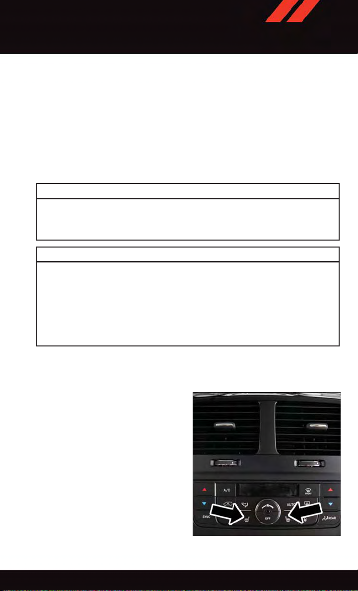
Front Heated Seats
The controls for front heated seats are located on the center instrument panel area.
•PresstheswitchoncetoselectHighlevel heating. Press the switch a second
time to select Low-level heating. Press
the switch a third time to shut the heating elements Off.
If the High-level setting is selected, the
system will automatically switch to Lowlevel after approximately 60 minutes. The
Low-level setting will turn Off automatically
after approximately 45 minutes.
Heated Seat Switch Location
25
Page 28
GETTING STARTED
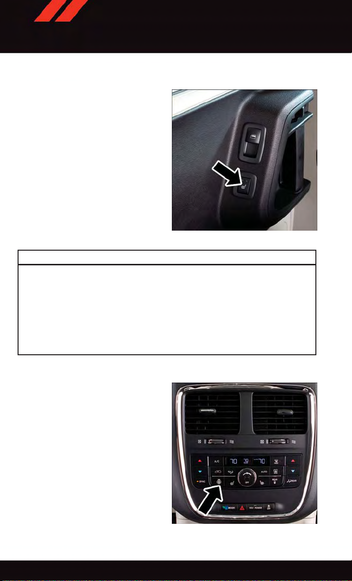
Second Row Heated Seats
Second row heated seat switches are located in the sliding door handle trim panels.
•PresstheswitchoncetoselectHighlevel heating. Press the switch a second
time to select Low-level heating. Press
the switch a third time to shut the heating elements Off.
If the High-level setting is selected, the
system will automatically switch to Lowlevel after approximately 60 minutes. The
Low-level setting will turn Off automatically
after approximately 45 minutes.
Heated Seat Switch Location
WARNING!
•Personswhoareunabletofeelpaintotheskinbecauseofadvancedage,chronic
illness, diabetes, spinal cord injury, medication, alcohol use, exhaustion or other
physical conditions must exercise care when using the seat heater. It may cause
burns even at low temperatures, especially if used for long periods of time.
•Donotplaceanythingontheseatthatinsulatesagainstheat,suchasablanketor
cushion. This may cause the seat heater to overheat. Sitting in a seat that has been
overheated could cause serious burns due to the increased surface temperature of
the seat.
HEATED STEERING WHEEL
The steering wheel contains a heating element that heats the steering wheel to one
temperature setting.
26
Heated Steering Wheel Switch Location
Page 29
GETTING STARTED
The heated steering wheel switch is located on the center instrument panel.
•PresstheswitchoncetoturntheheatingelementOn.Presstheswitchasecondtime
to turn the heating element Off.
Once the heated steering wheel has been turned on, it will operate for approximately 30
to 80 minutes before automatically shutting off. The heated steering wheel can shut off
early or may not turn on when the steering wheel is already warm.
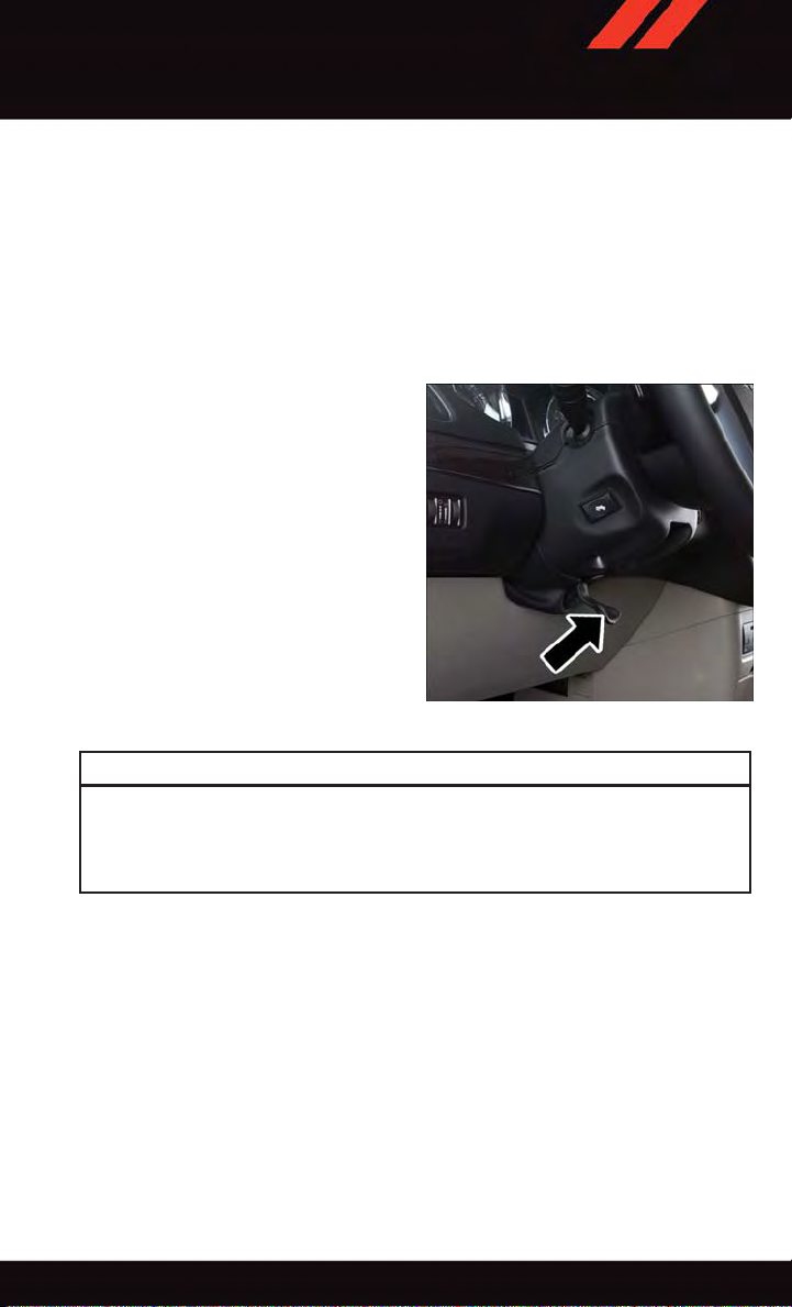
TILT/TELESCOPING STEERING COLUMN
The tilt steering column tilt lever is located
below the steering wheel.
•Pushdownonthetiltlevertounlockthe
steering column.
•Withonehandfirmlyonthesteering
wheel, move the steering column upward
or downward as desired.
•Tolengthenorshortenthesteeringcolumn, pull the steering wheel outward or
push it inward as desired.
•Pullupwardonthetiltlevertolockthe
column firmly in place.
Steering Column Lever
WARNING!
Do not adjust the steering wheel while driving. The tilt adjustment must be locked
while driving. Adjusting the steering wheel while driving or driving without the tilt
adjustment locked could cause the driver to lose control of the vehicle. Failure to follow
this warning may result in you and others being severely injured or killed.
27
Page 30
OPERATING YOUR VEHICLE
ENGINE BREAK-IN RECOMMENDATIONS
Alongbreak-inperiodisnotrequiredfortheengineanddrivetrain(transmissionandaxle)
in your vehicle.
Drive moderately during the first 300 miles (500 km). After the initial 60 miles (100 km),
speeds up to 50 or 55 mph (80 or 90 km/h) are desirable.
While cruising, brief full-throttle acceleration within the limits of local traffic laws
contributes to a good break-in. Wide-open throttle acceleration in low gear can be
detrimental and should be avoided.
The engine oil installed in the engine at the factory is a high-quality energy conserving type
lubricant. Oil changes should be consistent with anticipated climate conditions under
which vehicle operations will occur. For the recommended viscosity and quality grades,
refer to “Maintaining Y our Vehicle.”
NOTE:
Anewenginemayconsumesomeoilduringitsfirstfewthousandmiles(kilometers)of
operation. This should be considered a normal part of the break-in and not interpreted as
an indication of an engine problem or malfunction.
CAUTION!
Never use Non-Detergent Oil or Straight Mineral Oil in the engine or damage may result.
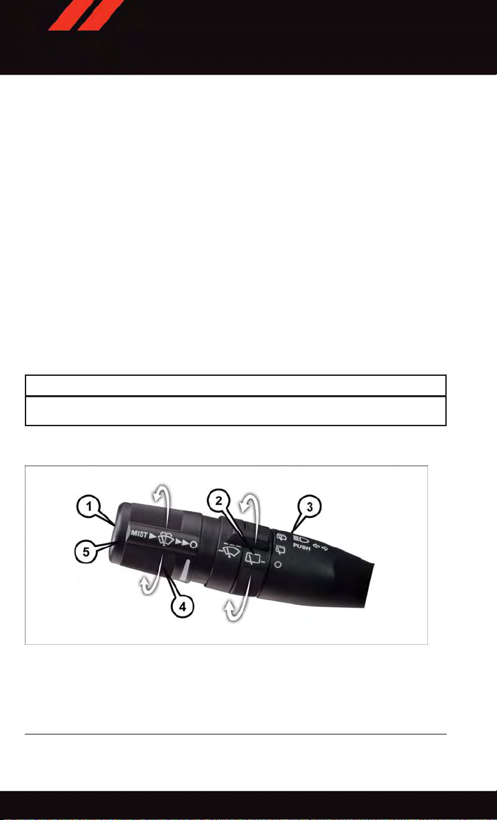
TURN SIGNAL/WIPER/WASHER/HIGH BEAM LEVER
Multifunction Lever
1—Mist(PushToFirstDetent)
2—RearWiper/Washer
3—PushLeverForHighBeams
4—FrontWipers
5—FrontWasher(PushToSecondDetent)
28
Page 31

OPERATING YOUR VEHICLE
Turn Signal/Lane Change Assist
•Taptheleverupordownonceandtheturnsignal(rightorleft)willflashthreetimesand
automatically turn off.
NOTE:
Vehicles equipped with Blind Spot Monitoring will produce a visual alert and may be
programmed to produce an audible alert when signaling a lane change; refer to your
Owner’s Manual on the DVD for operation.
Front Wipers
Intermittent, Low And High Operation
•Rotatetheendofthelevertothefirstdetentpositionforoneoffiveintermittent
settings, the second detent for low wiper operation and the third detent for high wiper
operation.
Rain Sensing Wipers
This feature senses moisture on the vehicle’ s windshield and automatically activates the
wipers for the driver when the switch is in the intermittent positions. Refer to “Programmable Features” in “Electronics” for further details.
Mist
•Pushtheendoftheleverinwardtothefirstdetentwhenasinglewipeisdesired.
NOTE:
The mist feature does not activate the washer pump; therefore, no washer fluid will be
sprayed on the windshield. The wash function must be activated in order to spray the
windshield with washer fluid.
Washer Operation
•Pushtheendoftheleverinwardtotheseconddetentandholdforaslongassprayis
desired.
Rear Wiper
•Rotatethecenterportionoftheleverforwardtothefirstdetentforrearwiperoperation.
Rear Washer
•Rotatethecenterportionoftheleverpastthefirstdetenttoactivatetherearwasher.
High Beams
•Pushtheleverawayfromyoutoactivatethehighbeams.
Ahighbeamsymbolwillilluminateintheclustertoindicatethehighbeamsareon.
NOTE:
For safe driving, turn off the high beams when oncoming traffic is present to prevent
headlight glare and as a courtesy to other motorists.
29
Page 32

OPERATING YOUR VEHICLE
Flash To Pass
•Pullthelevertowardyoutoactivatethehighbeams.Thehighbeamswillremainon
until the lever is released.
HEADLIGHT SWITCH AND HALO LIGHT SWITCH
Automatic Headlights/Parking Lights/Headlights
•Rotatetheheadlightswitch,locatedon
the instrument panel to the left of the
steering wheel, to the first detent for
parking lights
detent for headlights
•Withtheparkinglightsorlowbeam
headlights on, push the headlight switch
once for fog lights.
•RotatetheheadlightswitchtoAUTOfor
Automatic Headlights.
•WhensettoAUTO,thesystemautomatically turns the headlights on or off based
on ambient light levels.
Instrument Panel Dimmer
•Rotatethedimmercontroltotheextreme bottom position to fully dim the
instrument panel lights and prevent the
interior lights from illuminating when a
door is opened.
•Rotatethedimmercontroluptoincreasethebrightnessoftheinstrumentpanelwhen
the parking lights or headlights are on.
•Rotatethedimmercontroluptothenextdetentpositiontofullybrightentheodometer
and radio when the parking lights or headlights are on.
•Rotatethedimmercontroluptothelastdetentpositiontoturnontheinteriorlighting.
If your vehicle is equipped with a touchscreen, the dimming is programmable through the
Uconnect
Panel” in the Owner's Manual on the DVD for further details.
®
system. Refer to “Uconnect®Settings ” in “Understanding Your Instrument
and to the second
.
Headlight Switch/Halo Light Switch
1—Auto
2—PushFogLight
3—RotateHaloLightDimmerControl
4—RotateDimmerControl
5—RotateHeadlightSwitch
Overhead (Halo) Light
•ToactivatetheHalolights,rotatetheHaloswitchcontrolupwardordownwardto
increase or decrease the lighting.
30
Page 33

OPERATING YOUR VEHICLE
ELECTRONIC RANGE SELECTION (ERS)
Electronic Range Select (ERS) allows you to limit the highest available transmission gear,
and can be activated during any driving condition. When towing a trailer or operating the
vehicle in off-road conditions, using ERS shift control will help you maximize both
performance and engine braking.
•ToshiftfromDRIVEmodetoERSmode,
move the shift lever to the left (-) once.
The current gear will be maintained as
the top gear. To disable ERS, simply
press and hold the shift lever to the right
(+) until “D” is displayed in the instrument cluster odometer.
Switching between ERS and DRIVE mode
can be done at any vehicle speed.
Refer to your Owner's Manual on the DVD
for further details.
Electronic Range Select
31
Page 34

OPERATING YOUR VEHICLE
FUEL ECONOMY (ECON) MODE
The Fuel Economy (ECON) mode can improve the vehicle’s overall fuel economy during
normal driving conditions.
•PresstheECONswitchinthecenter
stack of the instrument panel and a
green light will indicate the ECON mode
is engaged.
When the ECON Mode is engaged, the vehicle control systems will be able to change
the following:
•Thetransmissionwillupshiftsoonerand
downshift later.
•Thetransmissionwillskipselectgears
during shifts to allow the engine to operate at lower speeds.
•Thetorqueconverterclutchmayengage
sooner (lower engine rpm’s) and remain
on longer.
•Theengineidlespeedwillbelower.
•Theoveralldrivingperformancewillbemoreconservative.
ECON Switch Location
32
Page 35

OPERATING YOUR VEHICLE
THREE ZONE AUTOMATIC TEMPERATURE CONTROLS (ATC)
Three Zone Automatic Temperature Controls (ATC)
1—PushDriverTemp.ControlUp
2—PushAirRecirc.Button
3—PushA/CButton
4—PushModeControlButton
5—PushAUTOButton
6—PushFrontWindowDefrostButton
7—PushRearWindowDefrostButton
8—PushPassengerTemp.ControlUp
9—PushPassengerTemp.Control
Down
10 — Push Rear Control Button
11 — Push Rear Lock Button
12 — Push OFF Button
13 — Rotate Blower Control
14 — Push SYNC Button
15 — Push Driver T emp. Control Down
Automatic Operation
•PushtheAUTOmodebuttontoactivatetheATCsystem.
•Selectthedesiredtemperaturebypressingthetemperaturecontrolbuttonsforthe
driver or passenger.
•Thesystemwillmaintainthesettemperatureautomatically.
Air Conditioning (A/C)
•IftheairconditioningbuttonispushedwhileinAUTOmode,theindicatorlightwill
flash three times to indicate the cabin air is being controlled automatically .
SYNC Temperature Button
•PushtheSYNCbuttononcetocontroldriverandpassengertemperaturessimultaneously. Push the SYNC button a second time to control the temperatures individually.
33
Page 36

OPERATING YOUR VEHICLE
Air Recirculation
•UseRecirculationformaximumA/Coperation.
•Forwindowdefogging,turntheRecirculationbuttonoff.
•IftheRecirculationbuttonispressedwhenthesystemisinDefrostmodethe
Recirculation LED indicator will flash three times to indicate Recirculation mode is not
allowed.
Heated Mirrors
The mirrors are heated to melt frost or ice. This feature is activated whenever you turn on
the rear window defroster .
Rear Window Defroster
•Pushingtherearwindowdefrosterbuttonwillturnonthedefrosterforapproximately
10 minutes. An indicator in the button will illuminate when the rear window defroster
is on. For an additional 10 minutes of operation, push the button a second time.
Activating Rear Automatic Temperature Control
Rear Automatic Temperature Control
1—RotateBlowerControl
2—RotateTemperatureControl
3—RotateModeControl
•PushingtheREARLOCKbuttonfortheRearAutomaticTemperatureControl(ATC)
System from the front lower A TC panel, illuminates a LOCK symbol in the rear display.
The rear temperature and air source are controlled from the front lower A TC panel.
•RearsecondrowoccupantscanonlyadjusttherearATCcontrolwhentheREARLOCK
button is turned off.
•TheRearATCsystemislocatedintheheadliner,nearthecenterofthevehicle.
4—RearTemperatureLock
5—RearBlowerControlAUTOMode
34
Page 37

OPERATING YOUR VEHICLE
PARKSENSE® REAR PARK ASSIST
If an object is detected behind the rear bumper while the vehicle is in REVERSE, a
warning will display in the instrument cluster and a tone will sound, (closer the object the
faster the tone) that changes speed depending on the distance of the object from the
bumper, will sound.
When the Instrument Cluster reads either “Clean Sensor” or “Blinded”, clean off the
bumper sensors to see if the condition is corrected.
PARKVIEW® REAR BACK-UP CAMERA
You can se e an on-s cr een imag e of the r ear of yo ur vehic le whene ver the s hift lever is put
into REVERSE. The ParkView
display screen, located on the center stack of the instrument panel.
If the radio display screen appears foggy, clean the camera lens located on the liftgate.
Refer to your Owner's Manual on the DVD for further details.
®
Rear Back-Up Camera image will be displayed on the radio
WARNING!
Drivers must be careful when backing up; even when using the ParkView®Rear
Back-Up Camera. Always check carefully behind your vehicle, and be sure to check for
pedestrians, animals, other vehicles, obstructions, or blind spots before backing up.
You m ust continue to pay atten tion while back ing up. Fa ilure to do so c an r esult in
serious injury or death.
BLIND SPOT MONITORING WITH REAR CROSS PATH
The Blind Spot Monitoring (BSM) system uses two radar-based sensors, located inside the
rear bumper fascia, to detect Highway licensable vehicles (automobiles, trucks, motorcycles etc.) that enter the blind spot zones from the rear/front/side of the vehicle.
The Blind Spot Monitoring (BSM) system warning light, located in the outside mirrors, will
illuminate if a vehicle moves into a blind spot zone.
The BSM system can also be configured to sound an audible (chime) alert and mute the
radio to notify you of objects that have entered the detection zones.
Refer to your Owner's Manual on the DVD for further details.
35
Page 38

ELECTRONICS
YOUR VEHICLE'S SOUND SYSTEM
1. Uconnect®Voice Command Button pg. 62
®
2. Uconnect
3. Steering Wheel Audio Controls (Left) pg. 58
4. Steering Wheel Audio Controls (Right) pg. 58
36
Phone Button pg. 59
Page 39

ELECTRONICS
5. USB port pg. 48
6. Audio Jack pg. 48
7. USB Port (inside upper glove box) pg. 58
37
Page 40

ELECTRONICS
Uconnect® 130
1—CDEjectButton
2—SeekDownButton
3—SeekUpButton
4—AM/FMButton
5—DiscModeButton
6—AUXModeButton
7—RewindButton
8—FastForwardButton
Uconnect® 130
9—SetClockButton
10 — Audio Settings/Rotate T o Tune
11 — Radio Sales Code
12 — Audio Jack
13 — Set Preset/CD Random Play
14 — Station Presets Buttons
15 — ON/OFF/Rotate For Volume
NOTE:
•Yourradiohasmanyfeaturesthataddtothecomfortandconvenienceforyouandyour
passengers.
•Someoftheseradiofeaturesshouldnotbeusedwhendrivingbecausetheytakeyour
eyes from the road or your attention from driving.
38
Page 41

ELECTRONICS
Clock Setting
1. Push and hold the TIME button until the hours blink.
2. Turn the TUNE/SCROLL control knob to set the hours.
3. Push the TUNE/SCROLL control knob until the minutes begin to blink.
4. Turn the TUNE/SCROLL control knob to set the minutes.
5. Push the TUNE/SCROLL control knob to save the changes.
6. Push any button/knob or wait five seconds to exit.
Equalizer, Balance And Fade
1. Push the TUNE/SCROLL control knob and “BASS” will display.
2. Rotate the TUNE/SCROLL control knob to select the desired setting.
3. Continue pushing the TUNE/SCROLL control knob to display and set “MID RANGE,”
“TREBLE,” “BALANCE” and “FADE.”
Radio Operation
Seek Up/Down Buttons
•PushtoseekthroughradiostationsinAMorFMbands.
•Holdeitherbuttontobypassstationswithoutstopping.
Store Radio Presets
•PushtheSET/RNDorSET(dependingontheradio)buttononceandSET1willshow
in the display. Then select a preset button (1–6).
•Asecondstationmaybeaddedtoeachpushbutton.PushtheSET/RNDorSET
(depending on the radio) button twice and SET 2 will show in the display. Then select
apresetbutton(1–6).
39
Page 42

ELECTRONICS
CD/DISC Operation
Seek Up/Down Buttons
•PushtoseekthroughCDtracks.
•Holdeitherbuttontobypasstrackswithoutstopping.
SET/RND Or RND (Depending On Radio) Button (Random Play)
•PushthisbuttonwhiletheCDisplayingtoactivateRandomPlay.
•ThisfeatureplaystheselectionsontheCDinrandomordertoprovideaninteresting
change of pace.
Audio Jack Operation
The AUX/Audio Jack provides a means to connect a portable audio device, such as an
MP3 player or an iPod
stereo audio patch cable.
•
Pushing the AUX button will change the mode to auxiliary device if the Audio Jack is
connected, allowing the music from your portable device to play through the vehicle's
speakers.
The functions of the portable device are controlled using the device buttons, not the buttons on
the radio. However, the volume may be controlled using the radio or portable device.
®
,tothevehicle’ssoundsystem.Thisrequirestheuseofa3.5mm
40
Page 43

ELECTRONICS
Uconnect® 130 WITH SiriusXM SATELLITE RADIO
Uconnect® 130 With SiriusXM Satellite Radio
1—CDEjectButton
2—SeekDownButton
3—SeekUpButton
4—VoiceCommandButton
5—Uconnect
6—StationInfoButton
7—RewindButton
8—FastForwardButton
9—SetClockButton
10 — Audio Settings/Rotate T o Tune
11 — Radio Sales Code
®
Phone Button
12 — Audio Jack
13 — Set Preset/CD Random Play
14 — Station Preset Buttons
15 — ON/OFF/Rotate For Volume
16 — AM/FM Mode Button
17 — List Folders On A CD
18 — Satellite Radio Button
19 — Music Type Button
20 — Disc Mode Button
21 — Set Up Function Button
NOTE:
®
•YourradiomaynotbeequippedwiththeUconnect
Phone features. T o determine if your radio has these features, push the Voice Command
button on the radio. You will hear a voice prompt if you have the feature, or see a
message on the radio stating “Uconnect Phone not available” if you do not.
•Yourradiohasmanyfeaturesthataddtothecomfortandconvenienceofyouandyour
passengers. Some of these radio features should not be used when driving because they
take your eyes from the road or your attention from driving.
Voice Command and Uconnect
®
41
Page 44

ELECTRONICS
Clock Setting
1. Push and hold the TIME button until the hours blink.
2. Turn the TUNE/SCROLL control knob to set the hours.
3. Push the TUNE/SCROLL control knob until the minutes begin to blink.
4. Turn the TUNE/SCROLL control knob to set the minutes.
5. Push the TUNE/SCROLL control knob to save the changes.
6. Push any button/knob or wait five seconds to exit.
Equalizer, Balance And Fade
1. Push the TUNE/SCROLL control knob and “BASS” will display.
2. Rotate the TUNE/SCROLL control knob to select the desired setting.
3. Continue pushing the TUNE/SCROLL control knob to display and set “MID RANGE,”
“TREBLE,” “BALANCE” and “FADE.”
Radio Operation
Seek Up/Down Buttons
•PushtoseekthroughradiostationsinAM,FM,orSATbands.
•Holdeitherbuttontobypassstationswithoutstopping.
Store Radio Presets
•PushtheSET/RNDorSET(dependingontheradio)buttononceandSET1willshow
in the display. Then select a preset button (1–6).
•Asecondstationmaybeaddedtoeachpushbutton.PushtheSET/RNDorSET
(depending on the radio) button twice and SET 2 will show in the display. Then select
apresetbutton(1–6).
Music Type
NOTE:
The Music Type function only operates when in FM mode.
•PushtheMUSICTYPEbuttontoactivatethismode.PushtheMUSICTYPEbutton
again or turn the TUNE/SCROLL control knob to select the desired music type (Adult
Hits, Country, Jazz, Oldies, Rock, etc.).
•WhenamusictypeischosenandtheMusictypeisdisplayed,PusheitherSEEKbutton
and the radio will only search for stations with the selected music type.
SETUP Button
•PushingtheSETUPbuttonallowsyoutoselectbetweenitemsthatareavailableinthat
particular mode.
•TurntheTUNE/SCROLLcontrolknobtoscrollthroughtheentries.PushtheAUDIO/
SELECT button to select an entry and make changes.
42
Page 45

ELECTRONICS
SiriusXM Satellite Radio
SiriusXM services require subscriptions, sold separately after the 12-month trial included
with the new vehicle purchase. If you decide to continue your service at the end of your
trial subscription, the plan you choose will automatically renew and bill at then-current
rates until you call SiriusXM at 1-866-635-2349 to cancel. See SiriusXM Customer
Agreement for complete terms at www.siriusxm.com. All fees and programming subject to
change. Our satellite service is available only to those at least 18 and older in the 48
contiguous USA and D.C. Our Sirius satellite service is also available in PR (with coverage
limitations). Our Internet radio service is available throughout our satellite service area
and in AK and HI. ©2014 Sirius XM Radio Inc. Sirius, XM and all related marks and logos
are trademarks of Sirius XM Radio Inc.
SiriusXM Satellite Radio gives you over 130 channels, including 100% commercial-free
music from nearly every genre, plus all your favorite sports, news, talk and entertainment
channels – all with crystal clear, coast-to-coast coverage, all in one place and all at your
fingertips.
•ToaccessSiriusXMSatelliteRadio,pushtheSATbuttononthefaceplate.
CD/DISC Operation
Seek Up/Down Buttons
•PushtoseekthroughCDtracks.
•Holdeitherbuttontobypasstrackswithoutstopping.
SET/RND or RND (Depending On Radio) Button (Random Play)
•PushthisbuttonwhiletheCDisplayingtoactivateRandomPlay.
•ThisfeatureplaystheselectionsontheCDinrandomordertoprovideaninteresting
change of pace.
LIST Button
•PushtheLISTbuttontobringupalistofallfoldersontheCD.Scrollupordownthe
list by turning the TUNE/SCROLL control knob.
•Toselectafolderfromthelist,pushtheTUNE/SCROLLcontrolknobandtheradiowill
begin playing the files contained in that folder .
Audio Jack Operation
The AUX/Audio Jack provides a means to connect a portable audio device, such as an
MP3 player or an iPod
stereo audio patch cable.
•PushingtheAUXbuttonwillchangethemodetoauxiliarydeviceiftheAudioJackis
connected, allowing the music from your portable device to play through the vehicle's
speakers.
®
,tothevehicle’ssoundsystem.Thisrequirestheuseofa3.5mm
43
Page 46

ELECTRONICS
The functions of the portable device are controlled using the device buttons, not the
buttons on the radio. However , the volume may be controlled using the radio or portable
device.
Uconnect® 430/430N
Uconnect® 430/430N
1—VoiceCommandButton
2—Open/CloseDisplay
3—MenuButton
4—AudioSettingsButton
5—InternalHardDriveButton
6—USBPort
7—AudioJack
8—RadioSalesCode
9—ON/OFF/RotateForVolume
10 — Select Media Mode Button
11 — Radio Mode Button
12 — Uconnect
®
Phone Button
NOTE:
®
•YourradiomaynotbeequippedwiththeUconnect
Phone features. T o determine if your radio has these features, push the Voice Command
button on the radio. You will hear a voice prompt if you have the feature, or see a
message on the radio stating “Uconnect Phone not available” if you do not.
•Yourradiohasmanyfeaturesthataddtothecomfortandconvenienceofyouandyour
passengers. Some of these radio features should not be used when driving because they
take your eyes from the road or your attention from driving.
Voice Command and Uconnect
®
Clock Setting
1. Turn the radio on, then press the screen where the time is displayed.
2. Press the “User Clock” button on the touchscreen or the time display (Navigation radio
only).
44
Page 47

ELECTRONICS
3. Toadjust the hours, press either the “Hour Forward” or “Hour Backward” button on the
touchscreen.
4. To adjust the minutes, press either the “Minute Forward” or “Minute Backward”
button on the touchscreen.
5. To save the new time setting, press the screen where the word “Save” is displayed.
Menu
•PushtheMENUbuttononthefaceplatetoaccesstheSystemSetupmenuandtheMy
Files menu.
•PushtheMENUbuttononthefaceplateinanactivemode(SAT,CD,AUX,etc.)to
change mode specific settings.
Equalizer, Balance And Fade
Audio Control Menu
•PushtheAUDIObuttononthefaceplate
on the right side of the radio.
•Useeitherthe“arrow”buttonsonthe
touchscreen or the sliders to adjust
BASS, MID, and/or TREBLE.
•Pressthe“BAL/FADE”buttononthe
touchscreen and use either the “arrow”
buttons on the touchscreen or the crosshair to change Balance and Fade. The
“Center” button on the touchscreen resets the settings.
Display Settings
•PushtheMENUbuttononthefaceplate
and press the “Display Settings” button
on the touchscreen to access the Display
Settings menu.
•Selectthe“DaytimeColors”buttonon
the touchscreen to switch to manual daytime mode and to adjust the brightness
of the display using daytime colors.
•Selectthe“NighttimeColors”buttonon
the touchscreen to switch to manual
nighttime mode and to adjust the brightness of the display using nighttime colors.
•Selectthe“AutoColorMode”buttononthetouchscreentoswitchtoautomatic
daytime/nighttime mode and to control the brightness of the display using the dimmer
switch of the vehicle.
•Pressthe“Exit”buttononthetouchscreentosaveyoursettings.
Audio Control Menu
Display Settings
45
Page 48

ELECTRONICS
Radio Operation
1—RadioTunerTabs
2—IndividualPresets
3—Search/Browse
4—RadioStation/TrackInfo
5—SortPresets
Radio Operation
6—StationScan
7—SeekDown
8—DirectTune
9—SeekUp
•ToaccessRadioMode,pushtheRADIObuttonontheleftsideofthefaceplate,then
press the “AM,” “FM” or “SAT” button on the touchscreen to select the band.
Seek Up/Seek Down
Press the “SEEK UP” or “SEEK DOWN” buttons on the touchscreen to seek through radio
•
stations in AM, FM, or SAT bands. Hold either Seek to bypass stations without stopping.
Store Radio Presets
•Selecttheradiobandbypressingeitherthe“AM,”“FM,”or“SAT”buttononthe
touchscreen.
•Findthestationtostorebyeitherpressingthe“SEEKUP”or“SEEKDOWN”buttons
on the touchscreen, pressing the “Scan” button on the touchscreen, or by using the
“Direct Tune” button on the touchscreen.
46
Page 49

ELECTRONICS
•Oncethestationisfound,pressandholdoneofthe“PRESETS”buttonsonthe
touchscreen in the list to the right, until the preset key flashes and the station text on
the button on the touchscreen changes.
NOTE:
If the Presets are not visible on the right side of the screen, press the “PRESETS” button
on the touchscreen.
CD/DVD Disc Operation
CD/DVD Disc Operation
1—MediaSourceTabs
2—Folder/Track
3—OpenFolder
4—TrackInformation
5—SortTracks
•PushtheMEDIAbuttononthefaceplatetodisplaythemediasourcetabsatthetopof
the screen. Select the source by pressing the “HDD,” “DISC” or “AUX” media source
button on the touchscreen.
NOTE:
Your Touch screen Radio will usua lly a utomati cally switch to the appropr iate mode when
something is first connected or inserted into the system.
6—TrackScan
7—SeekDown
8—Play/Pause
9—SeekUp
47
Page 50

ELECTRONICS
Insert A CD/DVD Disc
•Toinsertadisc,pushtheLOADbuttononthefaceplate.
•Withtheprintedsideupwards,insertthediscintothediscslotoftheradio.Theradio
pulls the disc in automatically and closes the flip screen. The radio selects the
appropriate mode after the disc is recognized, and starts playing the first track. The
display shows “Reading...” during this process.
Seek Up/Seek Down
•PushtheSEEKUPorSEEKDOWNbuttonsonthefaceplatetoseekthroughtracksin
Disc Mode. Holding the SEEK UP button on the touchscreen will fast forward through
the track until the beginning of the track is reached; if still held it will fast-forward
through the next sequential track(s) (if random play node is not active) until released.
Holding the SEEK DOWN button on the touchscreen will fast-reverse through the track
until the beginning of the track is reached; if still held it will fast-reverse through the
next sequential track(s) (if random play node is not active) until released.
Audio Jack Operation
The AUX/Audio Jack provides a means to connect a portable audio device, such as an
MP3 player or an iPod
stereo audio patch cable.
•PushtheMEDIAbuttononthefaceplatethenthe“AUX”buttononthetouchscreento
change the mode to auxiliary device if the Audio Jack is connected, allowing the music
from your portable device to play through the vehicle's speakers.
NOTE:
The functions of the portable device are controlled using the device itself, not the buttons
on the radio. However , the volume may be controlled using the radio or portable device.
®
,tothevehicle’ssoundsystem.Thisrequirestheuseofa3.5mm
Hard Disk Drive (HDD) Operation
•TheHardDiskDrive(HDD)modegivesyouaccesstotheaudiofilesontheinternalhard
disk drive. It functions similar to a CD player, with the exception that the internal HDD
can hold more tracks.
•Itisalsopossibletoimportdisplaypicturestotheinternalharddiskdrive.Thepictures
can be displayed on the right half of the radio screen.
•BeforeusingtheHDDmode,youwillneedtocopysongsandpicturestotheinternal
hard drive. Songs and pictures can be added to the hard drive by using a CD or USB
device (e.g. thumb drive or memory stick).
NOTE:
•HDDsupportsonly.jpg/JPEGformatsforphotos.
•WMA/MP3FilesandSelectiveSongsfromaCDcanalsobeaddedtotheHDD.Seethe
Uconnect
®
430/430N User's Manual for more information.
48
Page 51

ELECTRONICS
Copying Music From CD
•PushtheLOADbuttononthefaceplate.
•Insertadisc,thenpushtheMYFILESbuttononthefaceplate.Selectthe“MYMUSIC”
button on the touchscreen.
•Pressthe“AddMusicFilestoHDD”buttononthetouchscreen,thenpressthe“Disc”
button on the touchscreen in the next screen to start the process.
NOTE:
•Youmightneedtoselectthefolderor
title depending on the CD, then push
“DONE” to start the copy process.
•Thecopyprogressisshowninthelower
left corner of the screen.
Copying Music From CD
Copying Music From USB
•TheUSBportontheradiofaceplateallowsyoutocopyfilestoyourharddrive.To
access, lift up on the cover.
•InsertaUSBdevice(e.g.thumbdriveormemorystick),thenselectthe“MYMUSIC”
button on the touchscreen.
•Pressthe“AddMusicFilestoHDD”buttononthetouchscreen,thenpressthe“Front
USB” button on the touchscreen in the next screen.
•Selectthefoldersortitlesyouwouldlike
to copy, then press the “SAVE” button on
the touchscreen to start the copy process.
•Tocopyallofthetitles,pressthe“ALL”
button on the touchscreen then press the
“SAVE” button on the touchscreen.
NOTE:
The copy progress is shown in the lower left
corner of the screen.
Copying Pictures To The HDD
•InserteitheraCDoraUSBdevicecontainingyourpicturesinJPEGformat.
•PushtheMYFILESbuttononthefaceplate.
•Pressthe“MyPictures”buttononthetouchscreentogetanoverviewofthecurrently
stored images, then press the “Add” button on the touchscreen.
•Pressthe“Disc”or“USB”buttononthetouchscreen,thenselectthefoldersor
pictures you wish to copy to the HDD. Use the “PAGE” buttons on the touchscreen to
page through the list of pictures.
Copying Music From USB
49
Page 52

ELECTRONICS
•Pressthedesiredpicturesorpressthe“All”buttononthetouchscreenforallpictures.
Confirm your selections by pressing the “SAVE” button on the touchscreen.
NOTE:
The copy progress is shown in the lower left
corner of the screen.
Display A Picture On The Radio Screen
•Oncetheimportiscomplete,thepictures will then be available in the “MY
PICTURES” screen.
•PushtheMYFILESbuttononthefaceplate, then press the “My Pictures” button on the touchscreen. Press the desired picture, press the “Set as Picture View”
button on the touchscreen and then press the “Exit” button on the touchscreen. Lastly
push the MENU button on the faceplate and press the “Picture View” button on the
touchscreen to display the chosen picture on the radio screen.
NOTE:
•AcheckmarkintheMyPicturesscreenindicatesthecurrentlyusedpicture.
•Youcanalsodeletepicturesbypressingthe“Delete”buttononthetouchscreen.
Playing Music From The HDD
•PushtheMEDIAbuttononthefaceplatetodisplaythemediasourcetabsatthetopof
the screen. Press the “HDD” button on the touchscreen. Press the desired track button
on the touchscreen to play or press the “SEARCH/BROWSE” button on the touchscreen to search by artist, by album, by song, by genre, from a folder, or from Favorites.
Copying Pictures To The HDD
50
Playing Music From The HDD
Browsing Music From The HDD
Page 53

ELECTRONICS
Cleaning Your Touchscreen Radio
•Donotsprayanyliquidorcausticchemicalsdirectlyonthescreen.Useacleananddry
micro fiber lens cleaning cloth to clean the touchscreen.
•Ifnecessary,usealint-freeclothdampenedwithacleaningsolutionsuchasisopropyl
alcohol or an isopropyl alcohol and water solution ratio of 50:50. Always follow the
solvent manufacturer's precautions and directions.
Garmin® Navigation
•Uconnect®430N integrates Garmin’s consumer-friendly navigation into your vehicle.
•Pressthe“NAV”buttonintheupperrightcornerofthetouchscreentoaccessthe
Changing The Navigation Voice Prompt
Volume
1. Program a destination.
2. While traveling on your route, press the
3. The Navigation system will then repeat
4. While the Navigation system is speaking, use the ON/OFF VOLUME rotary knob to
NOTE:
For your own safety and the safety of others, it is not possible to use certain features while
the vehicle is in motion.
®
Garmin
Navigation system.
upper left area of the map screen where
your next turn is displayed.
the distance to your next turn.
adjust the volume to a comfortable level. Please note the volume setting for Navigation
Voice Prompt is different than the audio system.
Navigation includes a database with over six million points of interest.
Garmin® Navigation
Main Navigation Menu
Finding Points Of Interest
•FromthemainNavigationmenu,pressthe“WhereTo?”buttononthetouchscreen,
then press the “Points of Interest” button on the touchscreen.
•SelectaCategory,thenasubcategory,if
necessary.
•Selectyourdestinationandpressthe
“Go” button on the touchscreen.
Main Navigation Menu
51
Page 54

ELECTRONICS
Finding A Place By Spelling The Name
•FromtheMainNavigationMenupressthe“WhereTo?”buttononthetouchscreen.
Next, press the “Points of Interest” button on the touchscreen then press the “Spell
Name” button on the touchscreen.
•Enterthenameofyourdestination.
•Pressthe“Done”buttononthetouchscreen.
•Selectyourdestinationandpressthe“Go”buttononthetouchscreen.
Entering A Destination Address
•FromthemainNavigationmenupressthe“WhereTo?”buttononthetouchscreen,
then press the “Address” button on the touchscreen.
•Followtheon-screenpromptstoentertheaddressthenpressthe“Go”buttononthe
touchscreen.
Setting Your Home Location
•FromthemainNavigationmenupressthe"Tools"icon.Nextselectthe"MyData"folder
icon. Then select "Set Home Location."
•Youmayenteryouraddressdirectly,useyourcurrentlocationasyourhomeaddress,or
choose from recently found locations.
Edit Home Location
•FromthemainNavigationmenupressthe“WhereTo?”buttononthetouchscreen,
then press the "Tools" icon. Next, press the "My Data" folder.
•Youmayenteranewaddressdirectly,useyourcurrentlocationorchoosefromrecently
found locations.
Go Home
•AHomelocationmustbesavedinthesystem.FromtheMainNavigationmenu,press
the “Where To?” button on the touchscreen, then press the “Go Home” button on the
touchscreen.
52
Page 55

ELECTRONICS
Following Your Route
Your route is mark ed w ith a magenta l in e on t he map. If you depa rt f rom the origi nal route,
your route is recalculated. A speed limit icon could appear as you travel on major
roadways.
Following Your Route
1—DistanceToNextTurn
2—CurrentLocation
3—ZoomIn
4—ZoomOut
5—CurrentSpeed
Adding A Via Point
To ad d a sto p bet w een t he cu rre n t lo c ati o n an d the e nd de s tin ati o n (V ia Po i nt) y ou m u st
be navigating a route.
•Pressthe“backarrow”iconmultipletimestoreturntotheMainNavigationmenu.
•Pressthe“WhereTo?”buttononthetouchscreen,thensearchfortheadditionalstop.
Select the destination you wish to add from the given search results.
•Pressthe“Go”buttononthetouchscreen,thenpress"AddasaViaPoint"buttonon
the touchscreen and press the "Done" button on the touchscreen.
6—DragMapForDifferentView
7—YourLocationOnTheMap
8—EstimatedTimeOfArrival
9—NavigationMainMenu
53
Page 56

ELECTRONICS
Taking A Detour
To tak e a det o ur yo u mus t b e nav iga t ing a r out e .
•Pressthe“backarrow”iconbuttononthetouchscreenmultipletimestoreturntothe
Main Navigation menu.
•Pressthe“Detour”buttononthetouchscreen.
NOTE:
If the route you are currently taking is the only reasonable option, the device might not
calculate a detour.
Acquiring Satellites
The GPS Satellite strength bars indicate the strength of your satellite reception.
•Acquiringsatellitesignalscantakeafewminutes.Whenatleastoneofthebarsis
green, your device has acquired satellite signals.
•Youmayexperiencedelaysreceivingsatellitesignalswheninareaswithanobstructed
view to the sky, such as garages, tunnels, or large cities with tall buildings.
SiriusXM SATELLITE RADIO/TRAVEL LINK
•SiriusXMTravelLinkrequiresasubscription,soldseparatelyafterthefive(5)yeartrial
subscription included with your vehicle purchase.
•SiriusXMTravelLinkisonlyavailableintheUnitedStates.
•ThefollowingdescribesfeaturesthatareavailablewheninSiriusXMSatelliteRadio
mode.
•ToaccessSiriusXMSatelliteRadio,pushtheRADIO/MEDIAorRADIObuttononthe
faceplate, then press the “SA T” button on the touchscreen.
Info
•Pressthe“i”buttononthetouchscreentoviewdetailedinformationaboutthecurrent
Sirius XM Satellite channel.
SiriusXM Parental Controls
•SiriusXM offers the option to permanently block selected channels. Call
1-888-539-7474 and request the Family Package.
• Uconnect® 430/430N and 730N: Push the “MENU” button on the faceplate while in
SiriusXM™ Satellite Radio Mode, then press the “Channel Lock” to enable and/or
disable desired channels. The SEEK and SCAN function will then only display channels
without Channel lock.
54
Page 57

ELECTRONICS
Search/Browse
•Pressthe“magnifyingglass”buttononthetouchscreentosearch/browsetheSiriusXM
channel listing by Favorites and Categories such as Song, Artist and Channel Name.
The Search/Browse also allows you to manage your Favorites.
SAT Browse
SiriusXM™ Satellite Radio Favorites (SAT Favorites)
•Youcansave50favoritesongsand50favoriteartists.
•Pressthe“AddFavorite”buttononthe
touchscreen to add either the song or the
artist of the currently playing program to
the SAT Favorites list. The favorite star
will appear in the upper right corner,
below the “SAT” button on the touchscreen.
•Youwillseeafavoritestarindicatorin
the upper right side of the screen below
the “SAT” button on the touchscreen
and a pop up will alert you that a favorite song or artist is currently playing on one of the
SiriusXM™ satellite radio channels.
NOTE:
Refer to your Uconnect
430N Supplement Manual for more information.
®
730N or 430/
Manage SAT Favorites
Favorites Alert
55
Page 58

ELECTRONICS
Display SAT Favorites List
•Pressthe“Search/Browse”buttononthetouchscreenandselect“Favorites”fromthe
SA T Browse screen.
•Pressthedesiredfavoritesbuttononthe
touchscreen to switch the SA T tuner to
the corresponding channel.
You may use the “LIST” button on the
touchscreen to toggle between:
•FavoriteSongs
•FavoriteArtists
•Currentlyplayingfavorites
Replay
•WhileyouareinSATmode,youcanreplay44minutesofthecurrentSiriusXMchannel
(when the channel is changed, this audio buffer is erased). Push the REPLAY button to
listen to the stored audio.
You c an p ress the on-s creen contr ols to p ause and rewi nd a udio playba ck, press the SCA N
•
button to preview each of the tracks stored in the buffer, or select a track from the list.
The time displayed below the bar indicates
how much time is present between the
current buffer play position and the live
broadcast.
SAT Browse
SAT Favorites
SAT Mode Replay
Replay Option Option Description
Play/Pause
Rewind/RW Rewinds the channel content in steps of five seconds. Press and hold to
Fast Forward/FW Forwards the content, and works similarly to Rewind/RW. However, Fast
Press to pause content playback. Press Pause/Play again to resume playback.
rewind continuously, then release to begin playing content at that point.
Forward/FW can only be used when content has been previously rewound.
56
Page 59

ELECTRONICS
Replay Option Option Description
Replay Time Displays the amount of time in the upper center of the screen by which
Live
SiriusXM Travel Link (Uconnect® 730N & Uconnect® 430N Only)
•SiriusXMTravelLinkbringsawealthofusefulinformationintoyourvehicleandrightto
your fingertips.
•ToaccessTravelLink,pushtheMENUbuttononthefaceplate,thenthe“TravelLink”
button on the touchscreen.
your content lags the live channel.
Resumes playback of live content at any time while replaying rewound
content.
SiriusXM Travel Link
1 – Favorites
2 – Forecast
3 – Ski Info
4 – Fuel Prices
5 – Movies
6 – Sports
NOTE:
•SiriusXMTravelLinkrequiresasubscription,soldseparatelyafterthefive(5)yeartrial
subscription included with your vehicle purchase.
•SiriusXMTravelLinkisonlyavailableintheUnitedStates.
View and store your favorite location, theater and sport teams
for quick access.
View detailed weather conditions, forecasts and ski/
snowboarding conditions at resorts.
View ski and snowboarding conditions at ski resorts.
View detailed price information for fuel stations.
View information on movies that are playing at theaters.
View sports scores and upcoming events for all major sports.
57
Page 60

ELECTRONICS
STEERING WHEEL AUDIO CONTROLS
The steering wheel audio controls are located on the rear surface of the steering wheel.
Right Switch
•Pushtheswitchupordowntoincrease
or decrease the volume.
•Pushthebuttoninthecentertochange
modes AM/FM/CD/SAT.
Left Switch
•Pushtheswitchupordowntosearchfor
the next listenable station or select the
next or previous CD track.
•Pushthebuttoninthecentertoselect
the next preset station (radio) or to
change CDs if equipped with a CD
Changer.
iPod®/USB/MP3 CONTROL
There are many ways to play music from
®
iPod
/MP3 players or USB devices through
your vehicle's sound system.
•TheremoteUSBport,locatedwithinthe
upper glove compartment, allows you to
plug an iPod
system.
NOTE:
If equipped with the Uconnect
USB port on the faceplate allows the same
functions as the remote USB port.
Non-Touchscreen Radios: To hea r a udi o
from devices connected to the USB port,
push the “AUX” button faceplate.
®
into the vehicle's sound
®
730N, the
Steering Wheel Audio Controls
Remote USB Port
58
Page 61

ELECTRONICS
Touchscreen Radios:
“MEDIA” button on the faceplate, then press the “AUX” or “iPod
To hea r aud i o fro m dev ices c onn ecte d to t h e US B p ort , Pus h t he
®
”buttononthetouchscreen.
When connected to this feature:
®
•TheiPod
radio buttons to Play, Browse, and List
the iPod
•TheiPod
can be controlled using the
®
or external devices contents.
®
battery charges when plugged
into the USB port (if supported by the
specific audio device).
•
Compatible iPod®devices may also be con-
trollable using voice commands. Refer to
iPod®/USB/MP3 Control
the Owner's Manual on the DVD for details.
NOTE:
The USB port supports certain Mini, Classic, Nano, T ouch, and iPhone
®
devices. The
USB port also supports playing music from compatible external USB Mass Storage Class
memory devices. For supported audio file formats, refer to the USB Port section in the
Owner's Manual on the DVD. Refer to UconnectPhone.com for a list of tested iPod
Some iPod
Apple’s website for iPod
®
software versions may not fully support the USB port features. Please visit
®
software updates.
®
WARNING!
Do not plug in or remove the iPod®or external device while driving. Failure to follow this
warning could result in a collision.
Uconnect® Phone
The Uconnect®Phone is a voice-activated, hands-free, in-vehicle communications
system with Voice Command Capability that allows you to dial a phone number with your
mobile phone using simple voice commands (see Voice Command section).
•TodetermineifyourvehicleisequippedwithUconnect
Phone” button located on the radio faceplate. If your vehicle has this feature, you
will hear a voice prompt. If not, you will see a message on the radio “Uconnect
not available.”
NOTE:
To a cce ss the tut o ria l, pus h t he “Uc o nne ct
®
Phone” button .AftertheBEEP,say
“tutorial.” Push any button on the faceplate, or press any button on the touchscreen, to
cancel the tutorial.
•RefertoyourvehicleOwner'sManualontheDVDforfurtherdetails.
NOTE:
®
The Uconnect
Free Profile, Version 1.0 or higher. For Uconnect
Phone requires a mobile phone equipped with the Bluetooth®Hands-
®
UconnectPhone.com or call 1-877-855-8400. Canadian residents - visit
UconnectPhone.com or call, 1-800-465-2001 (English) or 1-800-387-9983 (French).
This site will provide specific instructions based on the type of mobile phone being paired.
®
Phone, push the “Uconnect
®
Phone
Customer Support: U.S. residents - visit
s.
®
59
Page 62

ELECTRONICS
Phone Pairing
NOTE:
Pairing is a one - time initial setup before using the phone. Prior to starting the pairing
procedure ensure all additional phones within the vehicle have their Bluetooth
®
1. Activate Bluetooth
2. Push the “Phone”
3. Wait for the “ready” prompt and BEEP .
4. After the BEEP, say ”setup” or “Uconnect device setup.”
5. After the BEEP, say “device pairing.”
6. After the BEEP, say “pair a device.”
7. Follow the audible prompts.
•Youwillbeaskedtosayafour-digit
Personal Identification Number (PIN),
which you will later need to enter into
your mobile phone. You can say any fourdigit PIN. You will not need to remember
this PIN after the initial pairing process.
•Youwillthenbepromptedtogivethe
phone pairing a name (each phone paired should have a unique name).
•Nextyouwillbeaskedtogivethisnewpairingapriorityof1through7(uptoseven
phones may be paired); 1 is the highest and 7 is the lowest priority . The system will only
connect to the highest priority phone that exists within the proximity of the vehicle.
•Youwillthenneedtostartthepairingprocedureonyourcellphone.Followthe
Bluetooth
pairing setup.
®
instructions in your cell phone Owner's Manual to complete the phone
on the phone you are pairing.
button to begin.
Mobile Phone Pairing
®
disabled.
60
Page 63

ELECTRONICS
Phonebook
Phonebook Download — Automatic Phonebook Transfer From Mobile Phone
If equipped and specifically supported by your phone, Uconnect
downloads names (text names) and number entries from your mobile phone’s phonebook.
Specific Bluetooth
Automatic T ransfer is indicated by a green arrow at the bottom of the screen. See
UconnectPhone.com for supported phones.
•Automaticdownloadandupdate,ifsupported, begins as soon as the Bluetooth
wireless phone connection is made to the
Uconnect
you start the vehicle.
NOTE:
The mobile phone may require authorization prior to download.
•Amaximumof1,000entriesperphone
will be downloaded and updated every time a phone is connected to the Uconnect
Phone.
•Dependingonthemaximumnumberofentriesdownloaded,theremaybeashortdelay
before the latest downloaded names can be used. Until then, if available, the previously
downloaded phonebook is available for use.
•Onlythephonebookofthecurrentlyconnectedmobilephoneisaccessible.
•Onlythemobilephone’sphonebookisdownloaded.TheSIMcardphonebookisnot
part of the Mobile phonebook.
•ThisdownloadedphonebookcannotbeeditedordeletedontheUconnect
These can only be edited on the mobile phone. The changes are transferred and
updated to Uconnect
®
Phones with Phone Book Access Profile may support this feature.
®
Phone. For example, after
®
Phone on the next phone connection.
®
®
Phone automatically
Uconnect® myPhone
®
Phone.
®
Making A Phone Call
•Pushthe“Phone”button .
•AftertheBEEP,say“dial”(or“call”aname).
•AftertheBEEP,saynumber(orname).
Receiving A Call — Accept (And End)
•Whenanincomingcallrings/isannouncedonUconnect®,pushthe“Phone”
button
•Toendacall,pushthe“Phone”button
.
.
Mute (Or Unmute) Microphone During Call
•Duringacall,pushthe“VoiceCommand”button
•AftertheBEEP,say“mute”(or“muteoff”).
.
61
Page 64

ELECTRONICS
Transfer Ongoing Call Between Handset And Vehicle
•Duringacall,pushthe“VoiceCommand”button .
•AftertheBEEP,say“transfercall.”
Changing The Volume
•Startadialoguebypushingthe“Phone”button ,thenadjustthevolumeduring
anormalcall.
•UsetheradioON/OFFVOLUMErotaryknobtoadjustthevolumetoacomfortablelevel
while the Uconnect
is different than the audio system.
•Anyvoicecommandedsystemshouldbeusedonlyinsafedrivingconditions
following applicable laws regarding phone use. Your attention should be focused on
safely operating the vehicle. Failure to do so may result in a collision causing you
and others to be severely injured or killed.
•Inanemergency,touseUconnect
•turnedon,
•pairedtoUconnect
•andhavenetworkcoverage.
Uconnect® VOICE COMMAND
®
system is speaking. Please note the volume setting for Uconnect
WARNING!
®
Phone, your mobile phone must be:
®
Phone,
®
Voice Command Operation
The Uconnect®Voice Command system allows you to control your AM, FM radio, satellite
radio, disc player, HDD, Uconnect
media devices.
•Whenyoupushthe“VoiceCommand”button
or steering wheel, you will hear a beep. The beep is your signal to give a command. If
you do not say a command within a few seconds, the system will present you with a list
of options. If you ever want to interrupt the system while it lists options, push the “Voice
Command” button
NOTE:
U.S. residents visit driveuconnect.com for more info on which voice command features
apply to your vehicle. Canadian residents visit driveuconnect.ca for more info on which
voice command features apply to your vehicle.
®
Phone, a memo recorder, and supported portable
located on the radio faceplate
,listenfortheBEEP,andsayyourcommand.
62
Page 65

ELECTRONICS
•Startadialoguebypushingthe“VoiceCommand”button ,youwillheara
beep. The beep is your signal to give a command. Below are a list of voice commands
for each of the different modes.
Voice Command Ready
Common Voice Commands (Examples)
While In: Voice Command Example:
“Radio AM” (to switch to the AM radio mode)
“Radio FM” (to switch to the FM radio mode)
“Satellite Radio” (to switch to the Satellite radio mode)
“Disc” (to switch to the disc mode)
Main Menu
Radio Mode
SiriusXM Satellite Radio
Mode
Disc Mode
“Bluetooth Streaming” (to switch to the Bluetooth
“Channel Number” (to change the channel by its spoken
"Channel Name" (to change the channel by its spoken name)
“USB” (to switch to the USB mode)
mode)
“Memo” (to switch to the memo recorder)
“System Setup” (to switch to system setup)
“Frequency” (to change the frequency)
“Next Station” (to select the next station)
“Previous Station” (to select the previous station)
“Radio Menu” (to switch to the radio menu)
“Main Menu” (to switch to the main menu)
number)
“Next Channel” (to select the next channel)
“Previous Channel” (to select the previous channel)
“List Channel” (to hear a list of available channels)
“Select Name” (to say the name of a channel)
“Radio Menu” (to switch to the radio menu)
“Main Menu” (to switch to the main menu)
“T rack” (#) (to change the track)
“Next Track” (to play the next track)
“Previous Track” (to play the previous track)
“Main Menu” (to switch to the main menu)
®
Streaming
63
Page 66

ELECTRONICS
While In: Voice Command Example:
To sw itc h to t h e vo ice r ec o rd e r mo de, s ay “ Mem o .” T he f o ll o wing are common voice commands for this mode: “New Memo”
(to record a new memo) — During the recording, you may push
the Voice Command button
ceed by saying one of the following commands:
—“Save”(tosavethememo)
—“Continue”(tocontinuerecording)
—“Delete”(todeletetherecording)
Memo Mode
—“PlayMemos”(toplaypreviouslyrecordedmemos)—Dur-
ing the playback you may push the Voice Command button
to stop playing memos. You proceed by saying one of
the following commands:
—“Repeat”(torepeatamemo)
—“Next”(toplaythenextmemo)
—“Previous”(toplaythepreviousmemo)
—“Delete”(todeleteamemo)
—“DeleteAll”(todeleteallmemos)
Voice Text Reply
If equipped with Uconnect®Voice Command, your Uconnect®430N/730N radio may be
able to play incoming Short Message Service (SMS) messages (text messages) through
the vehicle's sound system. It also allows you to respond by selecting from various
predefined phrases.
NOTE:
Not all phones are compatible with this feature. Refer to the phone compatibility list at
UconnectPhone.com. Connected mobile phones must be bluetooth-compatible and
paired with your radio.
•Pushthe“VoiceCommand”button
started.
NOTE:
To acc e ss th e tut o ria l , pus h the “Voi c e Com mand ” but t on
“tutorial.” Push any button on the faceplate or press any button on the touchscreen to
cancel the tutorial.
and after the BEEP , say “SMS” to get
to stop recording. You pro-
.AftertheBEEP,say
WARNING!
Any voice commanded system should be used only in safe driving conditions following
applicable laws regarding phone use. Your attention should be focused on safely
operating the vehicle. Failure to do so may result in a collision causing you and others
to be severely injured or killed.
64
Page 67

ELECTRONICS
Bluetooth® STREAMING AUDIO
If equipped with Uconnect®Voice Command, your Bluetooth®-equipped iPod®devices,
cell phones or other media players, may also be able to stream music to your vehicles
speakers. Your connected device must be Bluetooth
radio (see UconnectPhone.com for pairing instructions).
Non-Touchscreen Radios: Push the AUX
button on the faceplate until "BT" or “Audio
Streaming” is displayed on the radio
screen.
Touchscreen-Radios: Push the RADIO/
MEDIA or MEDIA button on the faceplate
and then press the “AUX” button on the
touchscreen.
VIDEO ENTERTAINMENT SYSTEM (VES™)
System Operation
The screen is located in the overhead compartment console. To lower the screen,
push the release button located in the center of the console rear of the screen.
The system may be controlled by the front
seat occupants using either the radio or
DVD player controls, or by the rear seat
occupants using the remote control.
The video screen displays information in a
split screen format. The left side of the
screen is referred to as Channel 1 and the
right side of the screen is referred to as
Channel 2. All modes except video modes
are displayed in a split screen format.
•
To use the h e adp hone s, p u sh t h e p owe r
button located on the right ear cup. Select
the channel on the headphones (1 or 2)
which corresponds to the channel selected on the desired video screen.
•ToreceiveVES™audiothroughthevehicle'ssoundsystem,presstheVES™buttonon
the touchscreen.
®
-compatible, and paired with your
Bluetooth® Streaming Audio
Video Entertainment System (VES™)
1—3rdRowScreen
2—2ndRowScreen
65
Page 68

ELECTRONICS
Operation Of The Touchscreen Radio/DVD Player/Blu-Ray® Player
To v iew a D VD/ B lu- ray, pus h t h e O PEN / CLO SE o r L OAD but ton on the fa c epl ate and in s ert
the disc or insert the disc into the optional DVD/Blu-ray player. Playback will begin
automatically after the DVD/Blu-ray is recognized by the disc drive. If playback does not
begin automatically when the disc is inserted into the DVD/Blu-ray player push the PLAY
button. If playback does not begin automatically after the disc is inserted into the
touchscreen radio follow these steps:
•PushtheMENUbuttononthefaceplate,thenpresstheRearVES™buttononthe
touchscreen. If a chapter list appears on the right side of the screen, press the HIDE
LIST button on the touchscreen to display the Rear VES™ control screen.
•Pressthe“1“buttononthetouchscreentoselectanaudiochannel,thenpressthe
“DISC” button on the touchscreen in the MEDIA column.
Operation Of The Remote Control
The remote control operates similarly to any DVD remote you may have used before and
allows the rear seat passengers to change stations, tracks, discs and audio/video modes.
The remote control is designed to control either channel by using the selector switch
located on the right side of the remote.
Connect the video game or other external media devices to the AUX jacks following the
color coding for the VES™ jacks.
•PushingthepowerbuttonwillturntheVES™systemON/OFF.
•PushingthemodebuttoncausestheMODESELECTIONmenutoappearontheVES™
screen. Use the remote control arrow buttons to scroll through the available modes, and
then push ENTER to select the desired mode.
Auxiliary Audio/Video Input Jacks
The AUX jacks are located on the drivers side rear trim panel behind the sliding door.
Connect the video game or other external media devices to the AUX jacks following the
color coding for the VES™ jacks.
Using either the touchscreen radio or remote control, select AUX from the REAR VES™
CONTROL or the MODE SELECTION screen.
Refer to the Uconnect
vehicle Owner's Manual on the DVD for further details.
®
Multimedia – Video Entertainment System (VES™) section in the
66
Page 69

ELECTRONICS
ELECTRONIC VEHICLE INFORMATION CENTER (EVIC)
The EVIC features a driver interactive display that is located in the instrument cluster.
Pushing the controls on the left side of the steering wheel allows the driver to select
vehicle information and Personal Settings. For additional information, refer to “Programmable Features” located in this guide.
•PushtheUP
ward through the main menus (Fuel
Economy, Vehicle Speed, T rip Info, Vehicle Info, Messages, Units, System SetUp, Turn Menu Off) and sub menus.
•PushtheDOWN
downward through the main menus and
sub menus.
•PushtheRIGHTarrow
access to main menus, sub menus or to
select a personal setting in the setup
menu.
•PushtheBACKbuttontoscrollbacktoa
previous menu or sub menu.
Compass Calibration
This compass is self-calibrating, which eliminates the need to set the compass manually.
When the vehicle is new, the compass may appear erratic, and the EVIC will display “CAL”
until the compass is calibrated.
You ma y als o cal ibrate the compas s by compl eting one or more 360 d egree turns (in an
area free from large metal or metallic objects) until the “CAL” message displayed in the
EVIC turns off. The compass will now function normally.
button to scroll up-
button to scroll
button for
EVIC Controls
PROGRAMMABLE FEATURES
Electronic Vehicle Information Center (EVIC) — If Equipped
Personal Settings allows you to set and recall features when the transmission is in PARK.
If the transmission is out of PARK or the vehicle begins moving, a warning message
SYSTEM SETUP NOT A VAILABLE VEHICLE NOT IN PARK displays when you try to select
“System Setup” from the main menu.
67
Page 70

ELECTRONICS
The EVIC can be used to program the following Personal Settings. Push the RIGHT arrow
button
through the settings. Push the RIGHT arrow button
•SelectLanguage •Key-OffPowerDelay
•Nav-TurnByTurn •IlluminatedApproach
•AutoLockDoors •HillStartAssist
•AutoUnlockDoors •FlasherswithSlidingDoor
•RemoteUnlockSequence •CalibrateCompass
•RemoteStartComfortSys. •CompassVariance
•HornwithRemoteLock •ParkAssist-IfEquipped
•FlashLampsWithLock •AutomaticHighBeams-IfEquipped
•HeadlampOffDelay •KeylessEnter-N-Go-IfEquipped
•HeadlampsWithWipers •RKELinkedToMemory-IfEquipped
Key Fob Programmable Features
The following features may also be programmed by using the Key Fob transmitter or the
ignition switch and driver's door lock switch.
NOTE:
Pushing the LOCK button while you are inside the vehicle will activate the Vehicle Security
Alarm. Opening a door with the Vehicle Security Alarm activated will cause the alarm to
sound. Push the UNLOCK button to deactivate the Vehicle Security Alarm.
Unlock On First Press
To unl ock e i the r the d r ive r 's si de, o r a ll do ors , o n the f irs t p ush o f the U N LOC K but t on:
•PushandholdtheLOCKbuttonforatleastfourseconds,butnolongerthan10
seconds. Then, push and hold the UNLOCK button while still holding the LOCK button.
•Releasebothbuttonsatthesametime.
Auto Unlock Doors On Exit
To hav e all o f t he ve hic l e doo rs un l ock w hen a n y doo r is op e ned :
•Enteryourvehicleandcloseallthedoors,andfastenyourseatbelt.
•CycletheignitionswitchbetweentheLOCKandONpositionfourtimes,endinginthe
LOCK position (do not start the engine).
•PushthepowerdoorUNLOCKswitchtounlockthedoors.Asinglechimewillindicate
that programming is complete.
Sound Horn With Lock
To tur n the h o rn ch irp o n o r off w hen t h e doo rs ar e l ock ed:
•PushtheLOCKbuttonandPANICbuttonatthesametimeforatleastfourseconds,
but no longer than 10 seconds.
•Releasebothbuttonsatthesametime.
68
until Personal Settings displays, then push the DOWN button to scroll
to change the setting.
Page 71

ELECTRONICS
Flashing Lights With Lock
The turn signal lights flash when the doors are locked, which can be turned on or off. T o
turn this feature on or off:
•PushandholdtheUNLOCKbuttonandtheLOCKbuttonatthesametimeforatleast
four seconds, but no longer than 10 seconds.
•Releasebothbuttonsatthesametime.
UNIVERSAL GARAGE DOOR OPENER (HomeLink®)
HomeLink®replaces up to three hand-held transmitters that operate devices such as
garage door openers, motorized gates, lighting or home security systems. The HomeLink
unit is powered by your vehicles 12 Volt battery.
The HomeLink
three different HomeLink
The HomeLink
®
buttons that are located in the overhead console or sunvisor designate the
®
®
channels.
indicator is located above the center button.
Before You Begin Programming HomeLink®
Ensure that your vehicle is parked outside
of the garage before you begin programming.
For efficient programming and accurate
transmission of the radio-frequency signal,
it is recommended that a new battery be
placed in the hand-held transmitter of the
device that is being programmed to the
HomeLink
To e r ase t he c han nel s , p l ace the i gni t ion
switch into the ON/RUN position, then
push and hold the two outside HomeLink
buttons (I and III) for up to 20 seconds or until the red indicator flashes.
NOTE:
Erasing all channels should only be performed when programming HomeLink
time. Do not erase channels when programming additional buttons.
If you have any problems, or require assistance, please call toll-free 1-800-355-3515 or,
on the Internet at HomeLink.com for information or assistance.
®
system.
®
HomeLink® Buttons
®
for the first
®
69
Page 72

ELECTRONICS
Programming A Rolling Code
NOTE:
For programming Garage Door Openers that were manufactured after 1995. These Garage
Door Openers can be identified by the “LEARN” or “TRAIN” button located where the
hanging antenna is attached to the Garage Door Opener. It is NOT the button that is
normally used to open and close the door . The name and color of the button may vary by
manufacturer.
1. Place the ignition switch into the ON/RUN position.
2. Place the hand-held transmitter 1 to 3 inches (3 to 8 cm) away from the HomeLink
button you wish to program while keeping the HomeLink®indicator light in view .
®
3. Push and hold the HomeLink
the hand-held transmitter button.
4. Continue to hold both buttons and observe the indicator light. The HomeLink
indicator will flash slowly and then rapidly after HomeLink®has received the frequency signal from the hand-held transmitter. Release both buttons after the indicator
light changes from slow to rapid.
5. At the garage door opener motor (in the garage), locate the “LEARN” or “TRAINING”
button. This can usually be found where the hanging antenna wire is attached to the
garage door opener motor. Firmly push and release the “LEARN” or “TRAINING”
button.
NOTE:
You have 30 secon ds in which to in itiate the ne xt step after the LEARN but ton has been
pushed.
6. Return to the vehicle and push the programmed HomeLink
button for two seconds each time). If the device is plugged in and activates,
programming is complete.
NOTE:
If the device does not activate, push the button a third time (for two seconds) to complete
the training.
7. To program the remaining two HomeLink
remaining button. DO NOT erase the channels.
button you want to program while you push and hold
®
button twice (holding the
®
buttons, repeat each step for each
®
®
70
Page 73

ELECTRONICS
Programming A Non-Rolling Code
NOTE:
For programming Garage Door Openers manufactured before 1995.
1. Turn the ignition switch to the ON/RUN position.
2. Place the hand-held transmitter 1 to 3 inches (3 to 8 cm) away from the HomeLink
button you wish to program while keeping the HomeLink®indicator light in view .
®
3. Push and hold the HomeLink
the hand-held transmitter button.
4. Continue to hold both buttons and observe the indicator light. The HomeLink
indicator will flash slowly and then rapidly after HomeLink®has received the frequency signal from the hand-held transmitter. Release both buttons after the indicator
light changes from slow to rapid.
5. Push and hold the programmed HomeLink
the indicator light stays on constantly, programming is complete and the garage door
(or device) should activate when the HomeLink
6. To program the two remaining HomeLink
remaining button. DO NOT erase the channels.
Using HomeLink®
To o p era t e, p ush a nd r ele a se t he p rog r amm ed H o meL ink®button. Activation will now
occur for the programmed device (e.g., garage door opener, gate operator, security system,
entry door lock, home/office lighting, etc.). The hand-held transmitter of the device may
also be used at any time.
button you want to program while you push and hold
®
button and observe the indicator light. If
®
button is pushed.
®
buttons, repeat each step for each
®
®
WARNING!
•Yourmotorizeddoororgatewillopenandclosewhileyouareprogrammingthe
universal transceiver . Do not program the transceiver if people or pets are in the
path of the door or gate.
•Donotrunyourvehicleinaclosedgarageorconfinedareawhileprogrammingthe
transceiver. Exhaust gas from your vehicle contains Carbon Monoxide (CO) which is
odorless and colorless. Carbon Monoxide is poisonous when inhaled and can cause
you and others to be severely injured or killed.
71
Page 74

UTILITY
Max. Tongue Wt.
360 lbs (163 kg)
Wt.)
(1,633 kg) *
Up to 2 persons &
Max. GTW (Gross Trailer
Luggage 3,600 lbs
335 lbs (152 kg)
300 lbs (136 kg)
3,350 lbs (1,519 kg) *
3,000 lbs (1,360 kg) *
3to5persons&Luggage
6to7persons&Luggage
TRAILER TOWING WEIGHTS (MAXIMUM TRAILER WEIGHT RATINGS)
72
Frontal Area
Wt. Rating)
GCWR (Gross Combined
Engine/Transmission
8,750 lbs (3,969 kg) 40 sq ft (3.72 sq m)
3.6L/Automatic
8,750 lbs (3,969 kg) 40 sq ft (3.72 sq m)
8,750 lbs (3,969 kg) 40 sq ft (3.72 sq m)
*ForvehiclesequippedwithFold-in-Floorseating,theGrossTrailerWeightmustbereducedby100lbs(45kg).Refertolocallawsformaxi-
mum trailer towing speeds.
weight referenced on the Tire and Loading Information placard.
NOTE: The trailer tongue weight must be considered as part of the combined weight of occupants and cargo, and should never exceed the
Page 75

UTILITY
RECREATIONAL TOWING (BEHIND MOTORHOME, ETC.)
Towing Condition Wheels OFF the Ground All Models
Flat Tow NONE
Dolly Tow
On Trailer ALL OK
Front OK
Rear
Recreational Towing — All Models
Recreational towing is allowed ONL Y if the front wheels are OFF the ground. This may be
accomplished using a tow dolly or vehicle trailer . If using a tow dolly, follow this procedure:
1. Properly secure the dolly to the tow vehicle, following the dolly manufacturer's
instructions.
2. Drive the front wheels onto the tow dolly .
3. Firmly apply the parking brake. Place the transmission in PARK.
4. Properly secure the front wheels to the dolly , following the dolly manufacturer's
instructions.
5. Release the parking brake.
CAUTION!
•DONOTflattowthisvehicle.Damagetothedrivetrainwillresult.
•Towingthisvehicleinviolationoftheaboverequirementscancausesevere
transmission damage. Damage from improper towing is not covered under the New
Vehicle Limited Warranty.
NOT ALLOWED
NOT ALLOWED
73
Page 76

WHAT TO DO IN EMERGENCIES
ROADSIDE ASSISTANCE
Dial toll-free 1-800-521-2779 for U.S. Residents or 1-800-363-4869 for Canadian
Residents.
•Provideyourname,vehicleidentificationnumber,licenseplatenumber,andyour
location, including the telephone number from which you are calling.
•Brieflydescribethenatureoftheproblemandanswerafewsimplequestions.
•Youwillbegiventhenameoftheserviceproviderandanestimatedtimeofarrival.If
you feel you are in an “unsafe situation”, please let us know. With your consent, we will
contact local police or safety authorities.
INSTRUMENT CLUSTER WARNING LIGHTS
-LowFuelWarningLight
This warning light indicates when the fuel level reaches approximately 2.0 gal (7.8 L).
This light will turn on and a single chime will sound.
-ChargingSystemLight
This light shows the status of the electrical charging system. If the charging system light
remains on, it means that the vehicle is experiencing a problem with the charging system.
We recommend you do not continue driving if the charging system light is on. Have the
vehicle serviced immediately.
-OilPressureWarningLight
This light indicates low engine oil pressure. If the light turns on while driving, stop the
vehicle and shut off the engine as soon as possible. A chime will sound when this light
turns on.
We recommend you do not operate the vehicle or engine damage will occur. Have the
vehicle serviced immediately.
-Anti-LockBrake(ABS)Light
This light monitors the Anti-Lock Brake System (ABS).
If the light is not on during starting, stays on or turns on while driving, we recommend you
contact the nearest authorized dealer and have the vehicle serviced immediately.
-AirBagWarningLight
If the light is not on during starting, stays on, or turns on while driving, have the vehicle
serviced by an authorized dealer immediately.
-ElectronicThrottleControl(ETC)IndicatorLight
This light informs you of a problem with the system.
74
Page 77

WHAT TO DO IN EMERGENCIES
If a problem is detected, the light will come on while the engine is running. Cycle the
ignition when the vehicle has completely stopped and the shift lever is placed in the PARK
position; the light should turn off.
If the light remains lit with the engine running, your vehicle will usually be drivable.
However, see an authorized dealer immediately. If the light is flashing when the engine is
running, immediate service is required, and you may experience reduced performance, an
elevated/rough idle or engine stall, and your vehicle may require towing.
-TirePressureMonitoringSystem(TPMS)Light
Each tire, including the spare (if provided), should be checked monthly when cold and
inflated to the inflation pressure recommended by the vehicle manufacturer on the
vehicle placard or tire inflation pressure label. (If your vehicle has tires of a different size
than the size indicated on the vehicle placard or tire inflation pressure label, you should
determine the proper tire inflation pressure for those tires).
As an added safety feature, your vehicle has been equipped with a tire pressure
monitoring system (TPMS) that illuminates a low tire pressure telltale when one or more
of your tires is significantly under-inflated. Accordingly, when the low tire pressure telltale
illuminates, you should stop and check your tires as soon as possible and inflate them to
the proper pressure. Driving on a significantly under-inflated tire causes the tire to
overheat and can lead to tire failure. Under-inflation also reduces fuel efficiency and tire
tread life and may affect the vehicle’s handling and stopping ability.
IF THE LIGHT STARTS FLASHING INDICATING A LOW TIRE PRESSURE, ADJUST THE AIR
PRESSURE IN THE LOW TIRE TO THE AIR PRESSURE SHOWN ON THE VEHICLE PLACARD OR
TIRE INFLATION PRESSURE LABEL LOCATED ON THE DRIVER'S DOOR.
NOTE:
AFTER INFLA TION, THE VEHICLE MAY NEED TO BE DRIVEN FOR 20 MINUTES
BEFORE THE FLASHING LIGHT WILL TURN OFF.
Please note that the TPMS is not a substitute for proper tire maintenance, and it is the
driver’s responsibility to maintain correct tire pressure, even if under-inflation has not
reached the level to trigger illumination of the TPMS low tire pressure telltale.
Your ve hicle has al so bee n eq uipped with a TPMS malfu nction indica tor to ind icate when
the system is not operating properly. The TPMS malfunction indicator is combined with
the low tire pressure telltale.
When the system detects a malfunction, the telltale will flash for approximately one
minute and then remain continuously illuminated. This sequence will continue upon
subsequent vehicle start-ups as long as the malfunction exists. When the malfunction
indicator is illuminated, the system may not be able to detect or signal low tire pressure
as intended. TPMS malfunctions may occur for a variety of reasons, including the
installation of replacement or alternate tires or wheels on the vehicle that prevent the
TPMS from functioning properly. Always check the TPMS malfunction telltale after
replacing one or more tires or wheels on your vehicle to ensure that the replacement or
alternate tires and wheels allow the TPMS to continue to function properly .
75
Page 78

WHAT TO DO IN EMERGENCIES
NOTE:
Tire p res sur e s ch a nge b y ap p rox ima t ely 1 psi ( 7 kPa ) per 12° F ( 7° C ) of a i r te m per atu r e
change. Keep this in mind when checking tire pressure inside a garage, especially in the
Winter. Example: If garage temperature is 68°F (20°C), and the outside temperature is
32°F (0°C), then the cold tire inflation pressure should be increased by 3 psi (21 kPa),
which equals 1 psi (7 kPa) for every 12°F (7°C) for this outside temperature condition.
CAUTION!
The TPMS has been optimized for the original equipment tires and wheels. TPMS
pressures and warning have been established for the tire size equipped on your vehicle.
Undesirable system operation or sensor damage may result when using replacement
equipment that is not of the same size, type, and/or style. Aftermarket wheels can
cause sensor damage. Do not use tire sealant from a can, or balance beads if your
vehicle is equipped with a TPMS, as damage to the sensors may result.
-EngineTemperatureWarningLight
•Thislightwarnsofanoverheatedenginecondition.
•Ifthelightturnsonorflashescontinuouslywhiledriving,safelypulloverandstopthe
vehicle. If the A/C system is on, turn it off. Also, shift the transmission into NEUTRAL
and idle the vehicle. If the temperature reading does not return to normal, turn the
engine off immediately and call for service.
•Werecommendthatyoudonotoperatethevehicleorenginedamagewilloccur.Have
the vehicle serviced immediately.
WARNING!
Ahotenginecoolingsystemisdangerous.Youorotherscouldbebadlyburnedby
steam or boiling coolant.
-SeatBeltReminderLight
When the ignition switch is first turned to the ON/RUN position, this light will turn on for
four to eight seconds as a bulb check. During the bulb check, if the driver's seat belt is
unbuckled, a chime will sound. After the bulb check or when driving, if the driver or front
passenger seat belt remains unbuckled, the Seat Belt Indicator Light will flash or remain
on continuously. Refer to “Seat Belt Systems” in “Things To Know Before Starting” in your
Owner’s Manual on the DVD for further information.
-BrakeWarningLight
This light monitors various brake functions, including brake fluid level and parking brake
application. If the brake light turns on, it may indicate that the parking brake is applied,
that the brake fluid level is low, or that there is a problem with the anti-lock brake system
reservoir.
76
Page 79

WHAT TO DO IN EMERGENCIES
If the light remains on when the parking brake has been disengaged, and the fluid level is
at the full mark on the master cylinder reservoir, it indicates a possible brake hydraulic
system malfunction or that a problem with the Brake Booster has been detected by the
Anti-Lock Brake System (ABS)/Electronic Stability Control (ESC) system. In this case, the
light will remain on until the condition has been corrected. If the problem is related to the
brake booster, the ABS pump will run when applying the brake, and a brake pedal
pulsation may be felt during each stop.
The dual brake system provides a reserve braking capacity in the event of a failure to a
portion of the hydraulic system. A leak in either half of the dual brake system is indicated
by the Brake Warning Light, which will turn on when the brake fluid level in the master
cylinder has dropped below a specified level. The light will remain on until the cause is
corrected.
Vehicles equipped with the Anti-Lock Brake System (ABS) are also equipped with
Electronic Brake Force Distribution (EBD). In the event of an EBD failure, the Brake
Warning Light will turn on along with the ABS Light. Immediate repair to the ABS system
is required.
Operation of the Brake Warning Light can be checked by turning the ignition switch from
the OFF position to the ON/RUN position. The light should illuminate for approximately
two seconds. The light should then turn off unless the parking brake is applied or a brake
fault is detected. If the light does not illuminate, have the light inspected by an authorized
dealer.
The light also will turn on when the parking brake is applied with the ignition switch in the
ON/RUN position.
NOTE:
This light shows only that the parking brake is applied. It does not show the degree of
brake application.
WARNING!
Driving a vehicle with the red brake light on is dangerous. Part of the brake system may
have failed. It will take longer to stop the vehicle. You could have a collision. Have the
vehicle checked immediately.
-MalfunctionIndicatorLight(MIL)
Certain conditions, such as a loose or missing gas cap, poor fuel quality, etc., may
illuminate the MIL after engine start. The vehicle should be serviced if the light stays on
through several typical driving cycles. In most situations, the vehicle will drive normally
and not require towing.
If the MIL flashes when the engine is running, serious conditions may exist that could lead
to immediate loss of power or severe catalytic converter damage. We recommend you do
not operate the vehicle. Have the vehicle serviced immediately.
77
Page 80

WHAT TO DO IN EMERGENCIES
-ElectronicStabilityControl(ESC)IndicatorLight
If this indicator light flashes during acceleration, apply as little throttle as possible. While
driving, ease up on the accelerator. Adapt your speed and driving to the prevailing road
conditions. To improve the vehicle's traction when starting off in deep snow, sand or
gravel, it may be desirable to switch the ESC system off.
INSTRUMENT CLUSTER INDICATOR LIGHTS
-TurnSignalIndicator
The arrows will flash with the exterior turn signals when the turn signal lever is operated.
Atonewillchime,andaEVICmessagewillappearifeitherturnsignalisleftonformore
than 1 mile (1.6 km).
NOTE:
If either indicator flashes at a rapid rate, check for a defective outside light bulb.
-HighBeamIndicator
Indicates that headlights are on high beam.
-FrontFogLightIndicator
This indicator will illuminate when the front fog lights are on.
-VehicleSecurityLight
This light will flash rapidly for approximately 15 seconds when the vehicle security alarm
is arming. The light will flash at a slower speed continuously after the alarm is set. The
security light will also come on for about three seconds when the ignition is first turned on.
-ElectronicStabilityControl(ESC)OFFIndicatorLight
This light indicates the Electronic Stability Control (ESC) is off.
-ElectronicSpeedControlONIndicator
This indicator will illuminate when the electronic speed control has been activated to the
“ON” position.
-ElectronicSpeedControlSETIndicator
This indicator will illuminate when the cruising speed has been set.
OIL CHANGE REQUIRED
Your vehicl e is equi pped wi th an en gine oi l change indica tor syst em. The Oil Change
Required message will display in the EVIC display for approximately 10 seconds, after a
single chime has sounded, to indicate the next scheduled oil change interval. The engine
oil change indicator system is duty-cycle based, which means the engine oil change
interval may fluctuate dependent upon your personal driving style.
78
Page 81

WHAT TO DO IN EMERGENCIES
Unless reset, this message will continue to display each time you turn the ignition switch
to the ON/RUN position or cycle the ignition to the ON/RUN position if equipped with
Keyless Enter-N-Go™. To turn off the message temporarily, press and release the MENU
button. T o reset the oil change indicator system (after performing the scheduled maintenance), refer to the following procedure.
Vehicles Equipped With Keyless Enter-N-Go™
1. Without pressing the brake pedal, push the ENGINE STAR T/STOP button and cycle
the ignition to the ON/RUN position (do not start the engine).
2. Fully depress the accelerator pedal, slowly, three times within 10 seconds.
3. Without pressing the brake pedal, push the ENGINE START/STOP button once to
return the ignition to the OFF/LOCK position.
Vehicles Not Equipped With Keyless Enter-N-Go™
1. Turn the ignition switch to the ON/RUN position (do not start the engine).
2. Fully depress the accelerator pedal, slowly, three times within 10 seconds.
3. Turn the ignition switch to the OFF/LOCK position.
NOTE:
If the indicator message illuminates when you start the engine, the oil change indicator
system did not reset. If necessary, repeat these steps.
Resetting The Light After Servicing
Vehicles Equipped With Keyless Enter-N-Go™
1. Without pressing the brake pedal, push the ENGINE STAR T/STOP button and cycle
the ignition to the ON/RUN position (do not start the engine).
2. Fully depress the accelerator pedal, slowly, three times within 10 seconds.
3. Without pressing the brake pedal, push the ENGINE START/STOP button once to
return the ignition to the OFF/LOCK position.
Vehicles Not Equipped With Keyless Enter-N-Go™
1. Turn the ignition switch to the ON/RUN position (do not start the engine).
2. Fully depress the accelerator pedal, slowly, three times within 10 seconds.
3. Turn the ignition switch to the OFF/LOCK position.
NOTE:
If the indicator message illuminates when you start the vehicle, the oil change indicator
system did not reset. If necessary, repeat this procedure.
NOTE:
Resetting the oil life can also be done within the "Oil Life" menu under “Vehicle Info.”
79
Page 82

WHAT TO DO IN EMERGENCIES
IF YOUR ENGINE OVERHEATS
In any of the following situations, you can reduce the potential for overheating by taking
the appropriate action:
•Onthehighways—slowdown.
•Incitytraffic—whilestopped,shiftthetransmissiontoNEUTRAL,butdonotincrease
engine idle speed.
NOTE:
There are steps that you can take to slow down an impending overheat condition:
•Ifyourairconditioner(A/C)ison,turnitoff.TheA/Csystemaddsheattotheengine
cooling system and turning the A/C off can help remove this heat.
•Youcanalsoturnthetemperaturecontroltomaximumheat,themodecontroltofloor
and the blower control to high. This allows the heater core to act as a supplement to the
radiator and aids in removing heat from the engine cooling system.
CAUTION!
Driving with a hot cooling system could damage your vehicle. If the temperature gauge
reads HOT (H), pull over and stop the vehicle. Idle the vehicle with the air conditioner
turned off until the pointer drops back into the normal range. If the pointer remains on
HOT (H), and you hear continuous chimes, turn the engine off immediately, and call for
service.
WARNING!
You or others ca n be badly burn ed by hot engin e coolant ( antifre ez e) or steam f rom your
radiator. If you see or hear steam coming from under the hood, do not open the hood
until the radiator has had time to cool. Never try to open a cooling system pressure cap
when the radiator or coolant bottle is hot.
TIRE SERVICE KIT
Your v ehicle may be e quipped with a Tire Se rvice Kit.
Small punctures up to 1/4” (6 mm) in the tire tread can be sealed with the Tire Service Kit.
Foreign objects (e.g., screws or nails) should not be removed from the tire. The T ire Service
Kit can be used in outside temperatures down to approximately -4°F (-20°C).
This kit will provide a temporary tire seal, allowing you to drive your vehicle up to
100 miles (160 km) with a maximum speed of 55 mph (90 km/h).
80
Page 83

WHAT TO DO IN EMERGENCIES
Tire Service Kit Storage
•TheTireServiceKitisstowedbehindtherearleftsidetrimpanelintherearcargoarea.
Tire Service Kit Components And Operation
Using The Mode Select Knob And Hoses
Your Tire Se rvice Ki t is equipped with the
following symbols to indicate the air or sealant mode.
Selecting Air Mode
Turn the Mod e Sel ect Kno b (5) to t his
position for air pump operation only. Use
the Black Air Pump Hose (7) when selecting this mode.
Selecting Sealant Mode
Turn the Mod e Sel ect Kno b (5) to t his
position to inject the T ire Service Kit Sealant and to inflate the tire. Use the Sealant
Hose (clear hose) (6) when selecting this
mode.
Using The Power Button
Push and release the Power Button (4) once
to turn On the Tire Service Kit. Push and
release the Power Button (4) again to turn
Off the Tire Service Kit.
Using The Deflation Button
Press the Deflation Button (2) to reduce the
air pressure in the tire if it becomes over-inflated.
Tire Service Kit Components
1—SealantBottle
2—DeflationButton
3—PressureGauge
4—PowerButton
5—ModeSelectKnob
6—SealantHose(Clear)
7—AirPumpHose(Black)
8—PowerPlug(locatedonbottomside
of Tire Service Kit)
Tire Service Kit Usage Precautions
•ReplacetheTireServiceKitSealantBottle(1)andSealantHose(6)priortothe
expiration date (printed on the bottle label) to assure optimum operation of the system.
Refer to “Sealing A Tire With Tire Service Kit” section (F) “Sealant Bottle and Hose
Replacement.”
•TheSealantBottle(1)andSealantHose(6)areaonetireapplicationuse.Aftereach
use, always replace these components immediately at an authorized dealer.
81
Page 84

WHAT TO DO IN EMERGENCIES
•WhentheTireServiceKitsealantisinaliquidform,cleanwater,andadampclothwill
remove the material from the vehicle or tire and wheel components. Once the sealant
dries, it can easily be peeled off and properly discarded.
•Foroptimumperformance,makesurethevalvestemonthewheelisfreeofdebris
before connecting the Tire Service Kit.
You can use the Tire S ervice Kit air p ump to i nflate bicycl e ti res. T he k it als o co mes wi th t wo
•
needles, located in the Accessory Storage Compartment (on the bottom of the air pump) for
inflating sport balls, rafts, or similar inflatable items. However, use only the Air Pump Hose
(7) and make sure the Mode Select Knob (5) is in the Air Mode when inflating such items to
avoid injecting sealant into them. The T ire Service Kit Sealant is only intended to seal
punctures less than 1/4 inch (6 mm) diameter in the tread of your vehicle.
•DonotliftorcarrytheTireServiceKitbythehoses.
Sealing A Tire With Tire Service Kit
(A) Whenever You Stop To Use Tire Service Kit:
1. Pull over to a safe location and turn on the vehicle’ s Hazard Warning flashers.
2. Verify that the valve stem (on the wheel with the deflated tire) is in a position that is
near to the ground. This will allow the Tire Service Kit Hoses (6) and (7) to reach the
valve stem and keep the Tire Service Kit flat on the ground. This will provide the best
positioning of the kit when injecting the sealant into the deflated tire and running the
air pump. Move the vehicle as necessary to place the valve stem in this position before
proceeding.
3. Place the transmission in PARK (auto transmission) or in Gear (manual transmission)
and cycle the ignition to the OFF position.
4. Set the parking brake.
(B) Setting Up To Use Tire Service Kit:
1. Turn the Mode Select Knob (5) to the Sealant Mode position.
2. Uncoil the Sealant Hose (6) and then remove the cap from the fitting at the end of the
hose.
3. Place the Tire Service Kit flat on the ground next to the deflated tire.
4. Remove the cap from the valve stem and then screw the fitting at the end of the
Sealant Hose (6) onto the valve stem.
5. Uncoil the Power Plug (8) and insert the plug into the vehicle’s 12 Volt power outlet.
6. Do not remove foreign objects (e.g., screws or nails) from the tire.
(C) Injecting Tire Service Kit Sealant Into The Deflated Tire:
Always start the engine before turning ON the T ire Service Kit.
NOTE:
Manual transmission vehicles must have the parking brake engaged and the shift lever in
NEUTRAL.
82
Page 85

WHAT TO DO IN EMERGENCIES
After pressing the Power Button (4), the sealant (white fluid) will flow from the Sealant
Bottle (1) through the Sealant Hose (6) and into the tire.
NOTE:
Sealant may leak out through the puncture in the tire.
If the sealant (white fluid) does not flow within0–10seconds through the Sealant
Hose (6):
1. Press the Power Button (4) to turn Off the Tire Service Kit. Disconnect the Sealant
Hose (6) from the valve stem. Make sure the valve stem is free of debris. Reconnect the
Sealant Hose (6) to the valve stem. Check that the Mode Select Knob (5) is in the
Sealant Mode position and not Air Mode. Press the Power Button (4) to turn On the Tire
Service Kit.
2. Connect the Power Plug (8) to a different 12 Volt power outlet in your vehicle or
another vehicle, if available. Make sure the engine is running before turning ON the
Tire S erv i ce Ki t.
3. The Sealant Bottle (1) may be empty due to previous use. Call for assistance.
NOTE:
If the Mode Select Knob (5) is on Air Mode and the pump is operating, air will dispense
from the Air Pump Hose (7) only, not the Sealant Hose (6).
If the sealant (white fluid) does flow through the Sealant Hose (6):
1. Continue to operate the pump until sealant is no longer flowing through the hose
(typically takes 30 - 70 seconds). As the sealant flows through the Sealant Hose (6),
the Pressure Gauge (3) can read as high as 70 psi (4.8 Bar). The Pressure Gauge (3)
will decrease quickly from approximately 70 psi (4.8 Bar) to the actual tire pressure
when the Sealant Bottle (1) is empty.
2. The pump will start to inject air into the tire immediately after the Sealant Bottle (1)
is empty. Continue to operate the pump and inflate the tire to the pressure indicated
on the tire pressure label on the driver-side latch pillar (recommended pressure).
Check the tire pressure by looking at the Pressure Gauge (3).
If the tire does not inflate to at least 26 psi (1.8 Bar) pressure within 15 minutes:
The tire is too badly damaged. Do not attempt to drive the vehicle further. Call for
assistance.
NOTE:
If the tire becomes over-inflated, press the Deflation Button to reduce the tire pressure to
the recommended inflation pressure before continuing.
If the tire inflates to the recommended pressure or is at least 26 psi (1.8 Bar) pressure
within 15 minutes:
1. Press the Power Button (4) to turn off the Tire Service Kit.
2. Remove the Speed Limit sticker from the top of the Sealant Bottle (1) and place the
sticker on the instrument panel.
83
Page 86

WHAT TO DO IN EMERGENCIES
3. Immediately disconnect the Sealant Hose (6) from the valve stem, reinstall the cap on
the fitting at the end of the hose, and place the T ire Service Kit in the vehicle storage
location. Quickly proceed to (D) “Drive Vehicle.”
(D) Drive Vehicle:
Immediately after injecting sealant and inflating the tire, drive the vehicle 5 miles (8 km)
or 10 minutes to ensure distribution of the Tire Service Kit Sealant within the tire. Do not
exceed 55 mph (88 km/h).
(E) After Driving:
Pull over to a safe location. Refer to “Whenever You Stop to Use Tire Service Kit” before
continuing.
1. Turn the Mode Select Knob (5) to the Air Mode position.
2. Uncoil the Air Pump Hose (7) (black in color) and screw the fitting at the end of hose
(7) onto the valve stem.
3. Uncoil the power plug and insert the plug into the vehicles 12 Volt power outlet.
4. Check the pressure in the tire by reading the Pressure Gauge (3).
If tire pressure is less than 19 psi (1.3 Bar), the tire is too badly damaged. Do not attempt
to drive the vehicle further. Call for assistance.
If the tire pressure is 19 psi (1.3 Bar) or higher:
1. Press the Power Button (4) to turn on Tire Service Kit and inflate the tire to the pressure
indicated on the tire and loading information label on the driver-side door opening.
2. Disconnect the Tire Service Kit from the valve stem, reinstall the cap on the valve stem
and unplug from 12 Volt outlet.
3. Place the Tire Service Kit in its proper storage area in the vehicle.
4. Have the tire inspected and repaired or replaced at the earliest opportunity at an
authorized dealer or tire service center.
5. Remove the Speed Limit sticker from the instrument panel after the tire has been
repaired.
6. Replace the Sealant Bottle (1) and Sealant Hose (6) assembly at your authorized
dealer as soon as possible. Refer to “(F) Sealant Bottle and Hose Replacement.”
NOTE:
•Ifthetirebecomesover-inflated,presstheDeflationButtontoreducethetirepressure
to the recommended inflation pressure before continuing.
•Whenhavingthetireserviced,advisetheauthorizeddealerorservicecenterthatthe
tire has been sealed using the Tire Service Kit.
84
Page 87

WHAT TO DO IN EMERGENCIES
(F) Sealant Bottle And Hose Replacement:
1. Uncoil the Sealant Hose (6) (clear in color).
2. Locate the round Sealant Bottle release button in the recessed area under the sealant
bottle.
3. Press the Sealant Bottle release button. The Sealant Bottle (1) will pop up. Remove
the bottle and dispose of it accordingly.
4. Clean any remaining sealant from the Tire Service Kit housing.
5. Position the new Sealant Bottle (1) in the housing so that the Sealant Hose (6) aligns
with the hose slot in the front of the housing. Press the bottle into the housing. An
audible click will be heard indicating the bottle is locked into place.
6. Verify that the cap is installed on the fitting at the end of the Sealant Hose (6) and
return the hose to its storage area (located on the bottom of the air pump).
7. Return the Tire Service Kit to its storage location in the vehicle.
NOTE:
•ThemetalendfittingfromPowerPlug(8)maygethotafteruse,soitshouldbehandled
carefully.
•FailuretoreinstallthecaponthefittingattheendoftheSealantHose(6)canresult
in sealant contacting your skin, clothing, and the vehicle’ s interior. It can also result in
sealant contacting internal Tire Service Kit components which may cause permanent
damage to the kit.
85
Page 88

WHAT TO DO IN EMERGENCIES
WARNING!
•Donotattempttosealatireonthesideofthevehicleclosesttotraffic.Pullfar
enough off the road to avoid the danger of being hit when using the T ire Service Kit.
•DonotusetheTireServiceKitordrivethevehicleunderthefollowingcircumstances:
•Ifthepunctureinthetiretreadisapproximately1/4”.(6mm)orlarger.
•Ifthetirehasanysidewalldamage.
•Ifthetirehasanydamagefromdrivingwithextremelylowtirepressure.
•Ifthetirehasanydamagefromdrivingonaflattire.
•Ifthewheelhasanydamage.
•Ifyouareunsureoftheconditionofthetireorthewheel.
•KeeptheTireServiceKitawayfromopenflamesorheatsource.
•AlooseTireServiceKitthrownforwardinacollisionorhardstopcouldendangerthe
occupants of the vehicle. Always stow the Tire Service Kit in the place provided.
Failure to follow these warnings can result in injuries that are serious or fatal to you,
your passengers, and others around you.
•TakecarenottoallowthecontentsoftheTireServiceKittocomeincontactwith
hair, eyes, or clothing. The T ire Service Kit is harmful if inhaled, swallowed, or
absorbed through the skin. It causes skin, eye, and respiratory irritation. Flush
immediately with plenty of water if there is any contact with eyes or skin. Change
clothing as soon as possible, if there is any contact with clothing.
•TheTireServiceKitSealantsolutioncontainslatex.Incaseofanallergicreaction
or rash, consult a physician immediately . Keep the Tire Service Kit out of reach of
children. If swallowed, rinse mouth immediately with plenty of water and drink
plenty of water. Do not induce vomiting! Consult a physician immediately.
•TheTireServiceKitisnotapermanentflattirerepair.Havethetireinspectedand
repaired or replaced after using the Tire Service Kit. Do not exceed 55 mph
(88 km/h) until the tire is repaired or replaced. Failure to follow this warning can
result in injuries that are serious or fatal to you, your passengers, and others around
you.
JACKING AND TIRE CHANGING
Jack Location
Your v ehicle may be e quipped with jack ing a nd ti re changing equ ipment.
The jack, jack handle and winch handle tools are stowed behind the rear left side trim
panel in the rear cargo area. Turn the two cover latches to release the cover.
86
Page 89

WHAT TO DO IN EMERGENCIES
Remove the pouch containing the scissors jack, jack handle, and tools.
Spare Tire Removal
The spare tire is stowed inside a protective
cover located under the center of the vehicle between the front doors by means of a
cable winch mechanism. The “spare tire
drive” nut is located on the floor, under a
plastic cap at the front of the floor console
or under front super console forward bin
liner.
To Access Spare Tire Winch Drive Nut
To a c ces s t h e s p are ti r e w i nch dri ve n ut a nd
lower the spare tire, you will need to refer to
one of the following center console configurations.
Super Console
For vehicles equipped with the Super Console, the spare tire winch assembly drive nut is
located beneath the console.
1. Pull the lower drawer out from the rear of the floor console.
Jack Location
Drawer Location
1—LowerDrawer
2—FrontDrawerLiner
3—FrontDrawer
87
Page 90

WHAT TO DO IN EMERGENCIES
2. Open the front drawer to expose the storage compartment.
Storage Compartment Location
3. Remove the liner from the console's storage compartment to access the spare tire
winch drive nut.
Premium/Base/Cargo Center Console
Pull the Winch Cover assembly plug (if equipped) to access the winch drive nut.
Winch Drive Nut Location
Winch Cover Location
88
Page 91

WHAT TO DO IN EMERGENCIES
Spare Tire Tools
The tool pouch contains three pieces and can be assembled into a spare tire hook; to
remove the compact spare tire/cover assembly from under the vehicle, or a Winch
T-ha ndl e ; to ra ise/ low e r the c omp a ct sp are t i re/ cov e r ass e mbl y.
Assembled T-handle
A—SpareTireHook/T-handle
B—Extension1
C—Extension2
Assembling The Spare Tire Hook
A—SpareTireHook/T-handle
B—Extension1
C—Extension2
89
Page 92

WHAT TO DO IN EMERGENCIES
Spare Tire Removal Instructions
The spare tire is located under the vehicle beneath the center console area.
1. Assemble the spare tire tools into a
T-ha ndl e a nd pl a ce th e squ a re en d ove r
the spare tire winch drive nut.
Spare Tire Carrier
2. Rotate the nut to the left until the winch mechanism stops turning freely. This will
allow enough slack in the cable to allow you to pull the spare tire out from underneath
the vehicle.
3. Assemble the winch handle extensions
to form the spare tire hook, and pull the
spare tire from under the vehicle.
NOTE:
If either front tire is flat it may be necessary
to jack up the vehicle to remove the compact spare tire/cover assembly from under
the vehicle.
90
Spare Tire And Hook
1—SpareTire
2—SpareTireHook
Page 93

WHAT TO DO IN EMERGENCIES
4. Stand the tire/cover assembly upright and remove the wheel spacer by squeezing the
winch retaining tabs together. Push the retainer through the spare tire to release it from
the wheel.
Wheel Spacer
Preparations For Jacking
1. Park the vehicle on a firm, level surface. Avoid ice or slippery areas.
2. Turn on the Hazard Warning flasher.
3. Set the parking brake.
4. Place the shift lever into PARK.
5. Turn OFF the ignition.
NOTE:
Passengers should not remain in the vehicle
when the vehicle is being jacked.
•Blockboththefrontandrearofthe
wheel diagonally opposite the jacking position. For example, if changing the right
front tire, block the left rear wheel.
Wheel Blocked
91
Page 94

WHAT TO DO IN EMERGENCIES
Jacking Instructions
1. Loosen (but do not remove) the wheel
lug nuts by turning them to the left one
turn while the wheel is still on the
ground.
Warning Label
2. There are two jack engagement locations on each side of the vehicle body. These
locations are on the sill flange of the vehicle body.
92
Jack Engagement Locations
Page 95

WHAT TO DO IN EMERGENCIES
Rear jack locations are between a pair of down-facing tabs on the sill flange of the
vehicle side body.
Rear Jacking Location Engaged
Front jack location is on the sill flange of the vehicle body and is located 6 in
(150 mm) from door edge.
NOTE:
In some situations the jack may need to be
placed on its side in order to be pushed
under the vehicle. Return the jack to its
correct orientation once it is under the vehicle.
3. Place the wrench on the jack screw and
turn to the right until the jack head is
properly engaged in the described location. Do not raise the vehicle until you
are sure the jack is securely engaged.
4. Raise the vehicle by turning the jack
screw to the right, using the swivel wrench. Raise the vehicle only until the tire just
clears the surface and enough clearance is obtained to install the spare tire. Minimum
tire lift provides maximum stability.
Front Jacking Location Engaged
93
Page 96

WHAT TO DO IN EMERGENCIES
5. Remove the wheel lug nuts, for vehicles with wheel covers, remove the cover from the
wheel by hand. Do not pry the wheel cover off. Then pull the wheel off the hub.
6. Install the compact spare tire. Lightly tighten the lug nuts.
NOTE:
•Donotinstallthewheelcoveronthe
compact spare.
•Donotuseahammerorforcetoinstall
the wheel covers.
7. Lower the vehicle by turning the jack
screw to the left.
8. Finish tightening the lug nuts. Push
down on the wrench while at the end of
the handle for increased leverage.
Tigh ten t h e l u g nu t s in a sta r patt ern
until each nut has been tightened twice. The correct wheel nut tightness is 100 ft lbs
(135 N·m). If in doubt about the correct tightness, have them checked with a torque
wrench by your authorized dealer or at a service station.
9. Lower the jack to its fully-closed position.
10. Place the deflated (flat) tire and compact spare tire cover assembly in the rear cargo
area. Do not stow the deflated tire in the spare tire location. Have the full-sized tire
repaired or replaced, as soon as possible.
11. Stow the cable and wheel spacer before driving the vehicle. Reassemble the winch
handle extensions to form a “T” and fit the winch T-handle over the drive nut. Rotate
the nut to the right until the winch mechanism clicks at least three times.
NOTE:
Refer to the “Spare T ire Tools” section for instructions on assembling the T-handle.
12. Stow the jack, jack handle and winch handle tools back in the stowage compartment.
13. Check the compact spare tire pressure as soon as possible. Correct the tire pressure,
as required.
Installing Compact Spare
94
Page 97

WHAT TO DO IN EMERGENCIES
Securing The Spare Tire
1. Assemble the winch handle extensions to form a T-handle and fit the winch T-handle
over the drive nut. Rotate the nut to the left until the winch mechanism stops turning
freely. This will allow enough slack in the cable to allow you to pull the wheel spacer out
from under the vehicle.
2. Assemble the winch handle extensions to form the spare tire hook, and pull the wheel
spacer from under the vehicle.
3. Turn the compact spare tire so that the valve stem is down, and place the tire into the
spare tire/cover assembly. Slide the wheel spacer through the center of the wheel and
spare tire/cover assembly , so that the two retainer tabs snap out and engage the spare
tire cover on the opposite side.
4. Using the winch T-handle, rotate the drive nut to the right until the compact spare
tire/cover assembly is drawn into place against the underside of the vehicle.
5. Continue to rotate the nut to the right until you hear the winch mechanism click three
times. It cannot be overtightened. Check under the vehicle to ensure the compact
spare tire/cover assembly is positioned correctly against the underside of the vehicle.
Road Tire Installation
Vehicles Equipped With Wheel Covers
1. Mount the road tire on the axle.
2. To ease the installation process for steel wheels with wheel covers, install two lug nuts
on the mounting studs which are on each side of the valve stem. Install the lug nuts
with the cone shaped end of the nut toward the wheel. Lightly tighten the lug nuts.
3. Align the valve notch in the wheel cover
with the valve stem on the wheel. Install
the cover by hand, snapping the cover
over the two lug nuts. Do not use a
hammer or excessive force to install the
cover.
4. Install the remaining lug nuts with the
cone shaped end of the nut toward the
wheel. Lightly tighten the lug nuts.
5. Lower the vehicle to the ground by turning the jack handle counterclockwise.
1—ValveStem
2—ValveNotch
3—WheelLugNut
4—WheelCover
5—MountingStud
Wheel Cover Installation
95
Page 98

WHAT TO DO IN EMERGENCIES
6. Finish tightening the lug nuts. Push down on the wrench while at the end of the handle
for increased leverage. T ighten the lug nuts in a star pattern until each nut has been
tightened twice. The correct tightness of each lug nut is 100 ft/lbs (135 N·m). If in
doubt about the correct tightness, have them checked with a torque wrench by your
authorized dealer or service station.
7. After 25 miles (40 km) check the lug nut torque with a torque wrench to ensure that
all lug nuts are properly seated against the wheel.
Vehicles Without Wheel Covers
1. Mount the road tire on the axle.
2. Install the remaining lug nuts with the cone shaped end of the nut toward the wheel.
Lightly tighten the lug nuts.
3. Lower the vehicle to the ground by turning the jack handle counterclockwise.
4. Finish tightening the lug nuts. Push down on the wrench while at the end of the handle
for increased leverage. T ighten the lug nuts in a star pattern until each nut has been
tightened twice. The correct tightness of each lug nut is 100 ft/lbs (135 N·m). If in
doubt about the correct tightness, have them checked with a torque wrench by your
authorized dealer or service station.
5. After 25 miles (40 km) check the lug nut torque with a torque wrench to ensure that
all lug nuts are properly seated against the wheel.
CAUTION!
•ThewinchmechanismisdesignedforusewiththewinchT-handleonly.Useofair
wrench or other power tools is not recommended and can damage the winch.
•Donotattempttoraisethevehiclebyjackingonlocationsotherthanthose
indicated in the Jacking Instructions for this vehicle.
•Besuretomountthesparetirewiththevalvestemfacingoutward.Thevehicle
could be damaged if the spare tire is mounted incorrectly.
•Thecompactsparetire/coverassemblymustbeusedwhenthecompactsparetire
is stored. Failure to use this cover could drastically reduce the life of the compact
spare tire.
•Thewinchmechanismisdesignedspecificallytostowacompactsparetireonly.Do
not attempt to use the winch to stow the full size flat tire, or any other full-size tire.
Vehicle damage may result.
96
Page 99

WHAT TO DO IN EMERGENCIES
WARNING!
•Donotattempttochangeatireonthesideofthevehicleclosetomovingtraffic.
Pull far enough off the road to avoid the danger of being hit when operating the jack
or changing the wheel.
•Beingunderajacked-upvehicleisdangerous.Thevehiclecouldslipoffthejack
and fall on you. You could be crushed. Never put any part of your body under a
vehicle that is on a jack. If you need to get under a raised vehicle, take it to a service
center where it can be raised on a lift.
•Neverstartorruntheenginewhilethevehicleisonajack.
•Thejackisdesignedtobeusedasatoolforchangingtiresonly.Thejackshouldnot
be used to lift the vehicle for service purposes. The vehicle should be jacked on a
firm level surface only. Avoid ice or slippery areas.
•Carefullyfollowthesetirechangingwarningstohelppreventpersonalinjuryor
damage to your vehicle:
•Alwaysparkonafirm,levelsurfaceasfarfromtheedgeoftheroadwayaspossible
before raising the vehicle.
•TurnontheHazardWarningflasher.
•Blockthewheeldiagonallyoppositethewheeltoberaised.
•SettheparkingbrakefirmlyandsetanautomatictransmissioninPARK;amanual
transmission in REVERSE.
•Donotletanyonesitinthevehiclewhenitisonajack.
•Donotgetunderthevehiclewhenitisonajack.
•Onlyusethejackinthepositionsindicatedandforliftingthisvehicleduringatire
change.
•Ifworkingonorneararoadway,beextremelycarefulofmotortraffic.
•Toassurethatsparetires,flatorinflated,aresecurelystowed,sparesmustbe
stowed with the valve stem facing the ground.
•Raisingthevehiclehigherthannecessarycanmakethevehiclelessstable.Itcould
slip off the jack and hurt someone near it. Raise the vehicle only enough to remove
the tire.
•Toavoidtheriskofforcingthevehicleoffthejack,donottightenthewheelnuts
fully until the vehicle has been lowered. Failure to follow this warning may result in
personal injury.
•Aloosetireorjackthrownforwardinacollisionorhardstopcouldendangerthe
occupants of the vehicle. Always stow the jack parts and the spare tire in the places
provided. Have the deflated (flat) tire repaired or replaced immediately.
•Verifythatbothretainertabsofthewheelspacerhavebeenproperlyextended
through the center of the wheel and spare tire/cover assembly. Failure to properly
engage both retainer tabs could result in loss of the spare tire and cover assembly,
which will cause vehicle damage and may cause loss of vehicle control.
97
Page 100

WHAT TO DO IN EMERGENCIES
JUMP-STARTING
If your vehicle has a discharged battery it can be jump-started using a set of jumper cables
and a battery in another vehicle or by using a portable battery booster pack.
Jump-starting can be dangerous if done improperly so please follow the procedures in this
section carefully.
NOTE:
When using a portable battery booster pack
follow the manufacturer’s operating instructions and precautions.
Preparations For Jump-Start
•Thebatteryinyourvehicleislocatedon
the left side of the engine compartment.
•Settheparkingbrake,shifttheautomatic transmission into P ARK and turn
the ignition to LOCK.
•Turnofftheheater,radio,andallunnecessary electrical accessories.
•Ifusinganothervehicletojump-startthe
battery, park the vehicle within the
jumper cables reach, set the parking brake and make sure the ignition is OFF .
Positive Battery Post
Jump-Starting Procedure
1. Connect the positive (+) end of the jumper cable to the positive (+) post of the vehicle
with the discharged battery.
2. Connect the opposite end of the positive (+) jumper cable to the positive (+) post of the
booster battery.
3. Connect the negative (-) end of the jumper cable to the negative (-) post of the booster
battery.
4. Connect the opposite end of the negative (-) jumper cable to a good engine ground
(exposed metal part of the discharged vehicle’s engine) away from the battery and the
fuel injection system.
5. Start the engine in the vehicle that has the booster battery, let the engine idle a few
minutes, and then start the engine in the vehicle with the discharged battery.
Once the engine is started, remove the jumper cables in the reverse sequence:
1. Disconnect the negative (-) end of the jumper cable from the engine ground of the
vehicle with the discharged battery.
2. Disconnect the opposite end of the negative (-) jumper cable from the negative (-) post
of the booster battery.
98
 Loading...