

Page 1

DR
MANUAL TRANSMISSION - GETRAG 238 - SERVICE INFORMATION 21 - 69
MANUAL TRANSMISSION - GETRAG 238 - SERVICE
INFORMATION
TABLE OF CONTENTS
page page
MANUAL TRANSMISSION - GETRAG 238 -
SERVICE INFORMATION
DIAGNOSIS AND TESTING
MANUAL TRANSMISSION - GETRAG 238 . . . . . 70
STANDARD PROCEDURE
DRAIN AND FILL . . . . . . . . . . . . . . . . . . . . . . . . . . . . 70
REMOVAL . . . . . . . . . . . . . . . . . . . . . . . . . . . . . . . . . . . . 71
DISASSEMBLY . . . . . . . . . . . . . . . . . . . . . . . . . . . . . . . 73
CLEANING . . . . . . . . . . . . . . . . . . . . . . . . . . . . . . . . . . . 99
INSPECTION . . . . . . . . . . . . . . . . . . . . . . . . . . . . . . . . . 99
ASSEMBLY . . . . . . . . . . . . . . . . . . . . . . . . . . . . . . . . . . 102
INSTALLATION . . . . . . . . . . . . . . . . . . . . . . . . . . . . . . 134
SPECIFICATIONS
MANUAL TRANSMISSION - GETRAG 238 . . . . 135
SPECIAL TOOLS . . . . . . . . . . . . . . . . . . . . . . . . . . . . 137
Page 2
21 - 70 MANUAL TRANSMISSION - GETRAG 238 - SERVICE INFORMATION
DR
MANUAL TRANSMISSION - GETRAG 238 - SERVICE INFORMATION
DIAGNOSIS AND TESTING
MANUAL TRANSMISSION - GETRAG 238
LOW LUBRICANT LEVEL
A low transmission lubricant level is generally the result of a leak, inadequate lubricant fill or incorrect lubricant level
check.
Rear transmission leaks will be from the oil seals or transfer case front seal on 4x4.
Front transmission leaks will be from the front input shaft retainer seal. Lubricant may drip from the clutch housing
after extended operation. If leak is severe, it may contaminate the clutch disc.
Lubricant level check can only be made when the vehicle is level and allowing the lubricant to settle for a minute
before checking. This will ensure an accurate check and avoid an under or overfill condition.
HARD SHIFTING
Hard shifting can be caused by low lubricant level, improper or contaminated lubricants. This will cause noise,
excessive wear, internal bind, and hard shifting. Substantial lubricant leaks can result in gear, shift rail, synchro, and
bearing damage. The first indications of component damage is usually hard shifting and noise.
Shift component damage, clutch adjustment, worn pressure plate or disc, can increased shift effort. If clutch problem
is advanced, gear clash during shifts can result. Worn or damaged synchronizer rings can cause gear clash when
shifting into any forward gear. In some new or rebuilt transmissions, new synchro rings may tend to stick slightly
causing hard or noisy shifts. In most cases, this condition will decline as the rings wear-in.
TRANSMISSION NOISE
Most manual transmissions make some noise during normal operation. Rotating gears generate a mild whine that is
audible, but generally only at extreme speeds.
Severe, highly audible transmission noise is generally the initial indicator of a lubricant problem. Insufficient,
improper or contaminated lubricant will promote rapid wear of gears, synchronizer rings, shift rails, forks and bearings. The overheating caused by a lubricant problem, can also lead to gear and bearing damage.
STANDARD PROCEDURE
DRAIN AND FILL
1. Raise and support vehicle.
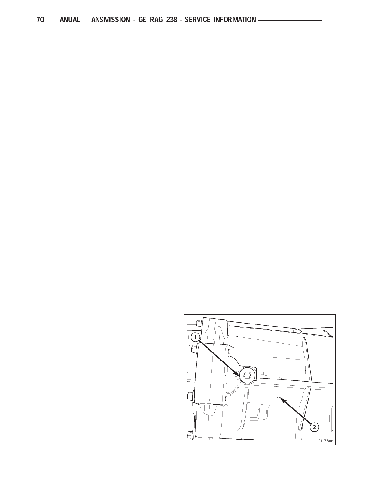
2. Remove drain plug (1) on transmission (2) and
drain fluid.
3. Install drain plug and tighten to 50 N·m (37 ft. lbs.).
Page 3
DR
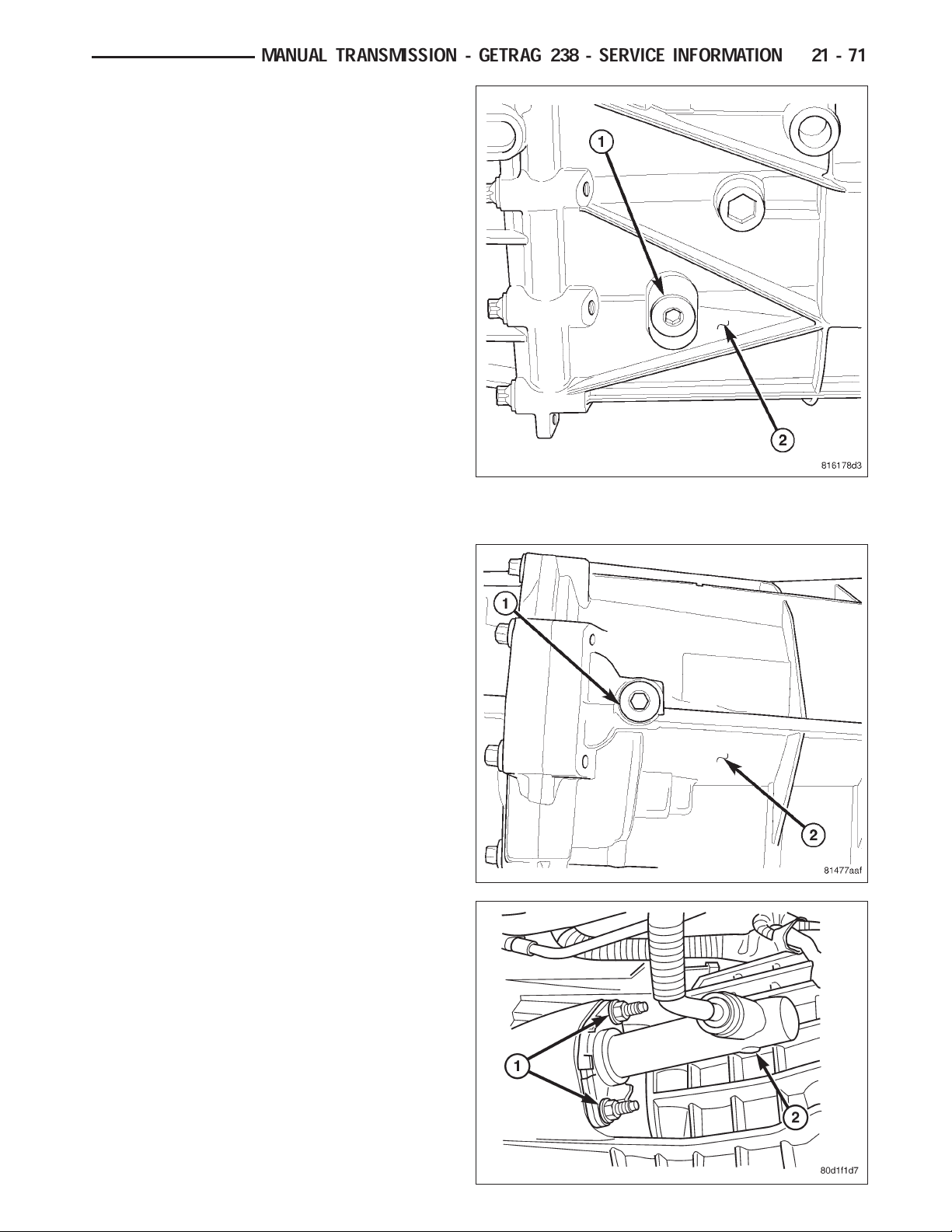
4. Remove fill plug (1) from side of transmission (2).
5. Fill transmission even with the bottom of the fill
hole.
6. Install fill plug and tighten to 50 N·m (37 ft. lbs.).
MANUAL TRANSMISSION - GETRAG 238 - SERVICE INFORMATION 21 - 71
REMOVAL
1. With vehicle in neutral, position vehicle on hoist.
2. Disconnect battery negative cable.
3. Remove shift boot bezel screws and slide boot
upward on shift lever extension.
4. Remove shift lever extension from the shift tower
and lever assembly.
5. Remove 4WD shift boot if equipped and remove
floor console.
6. Remove skid plate, if equipped.
7. Remove drain plug (1) from rear housing (2) and
drain fluid.
8. Mark propeller shaft/shafts and companion flange
yoke/yokes for installation reference and remove
propeller shaft/shafts.
9. Disconnect harness from clips on transmission
housing.
10. Remove transfer case linkage if equipped.
11. Remove transfer case mounting nuts and remove
transfer case if equipped.
12. Remove slave cylinder (2) mounting nut (1) and
remove cylinder.
Page 4
21 - 72 MANUAL TRANSMISSION - GETRAG 238 - SERVICE INFORMATION
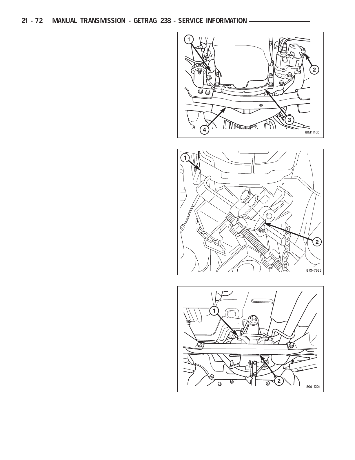
13. Remove starter motor (2), structural dust cover (3)
bolts to clutch housing, dust shield (1) bolt and
suspension crossmember (4).
CAUTION: Do not remove structural dust cover
from engine block. If cover is removed clutch
housing and cover must be aligned with the
engine.
14. Remove exhaust pipe from the exhaust manifolds.
15. Support engine with adjustable jack stand and
wood block.
16. Support and secure transmission (1) to a trans-
mission jack (2) with safety chains.
DR
17. Remove bolts from the rear transmission mount.
18. Remove the rear crossmember (2) and transmis-
sion mount (1).
19. Remove bolts attaching transmission to the
engine.
20. Move transmission rearward until input shaft is
clear of clutch disc and pressure plate. Then
lower jack and remove transmission from under
vehicle.
Page 5
DR
MANUAL TRANSMISSION - GETRAG 238 - SERVICE INFORMATION 21 - 73
DISASSEMBLY
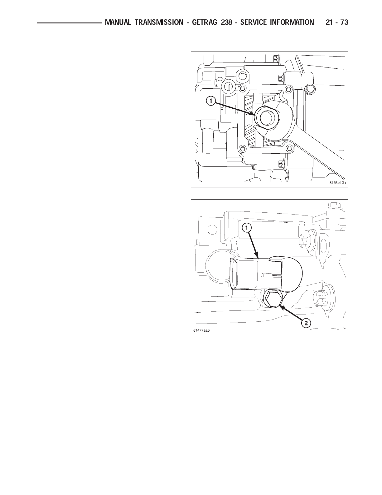
1. Remove shifter socket (1) from main shift rail.
2. Remove back up lamp switch (1) bolt (2) and
remove switch.
Page 6
21 - 74 MANUAL TRANSMISSION - GETRAG 238 - SERVICE INFORMATION
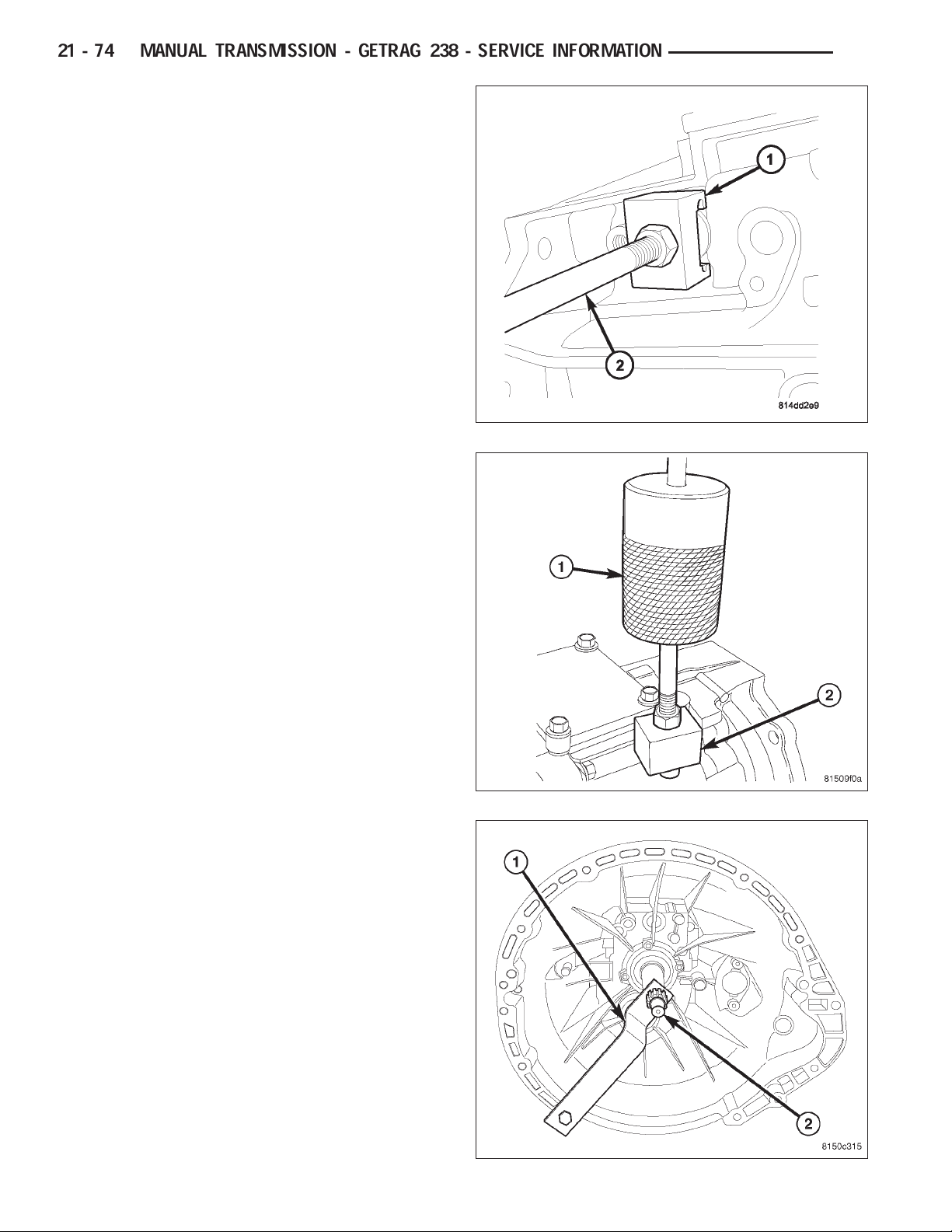
3. Remove large detent plug, next to back up lamp
switch opening with Puller 9583 (1) and Slide Hammer C-3752 (2).
4. Remove two small detent plugs on top of rear
housing with Puller 8870 (2) and Slide Hammer
C-3752 (1).
DR
5. Install Wrench 9586 (1) on input shaft (2).
Page 7
DR
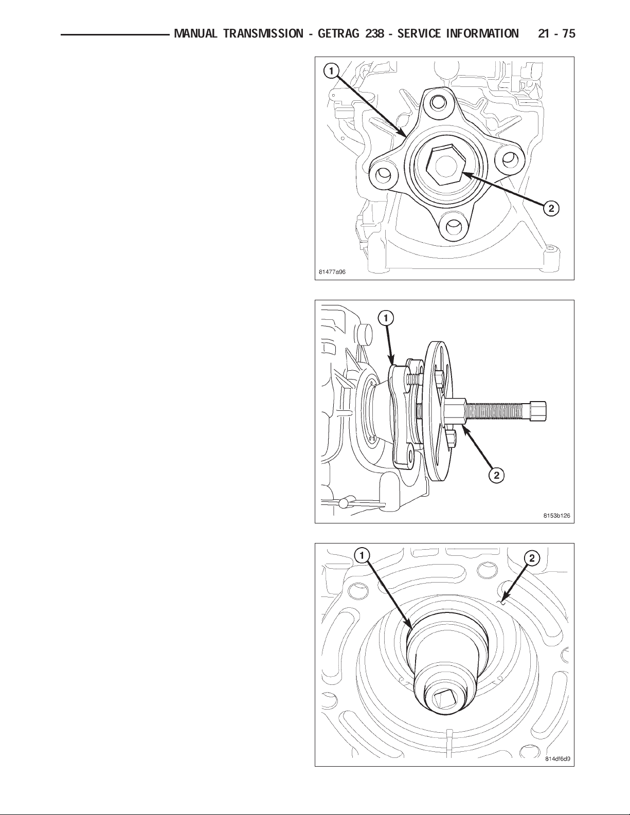
6. Remove output flange (1) nut (2) on 4x2 transmission.
7. Remove output flange (1) on 4x2 transmission with
Puller 8992 (2) and Button 9618-2.
MANUAL TRANSMISSION - GETRAG 238 - SERVICE INFORMATION 21 - 75
8. Remove output shaft nut with Socket 9584 (1) on
4x4 transmission (2).
9. Remove Wrench 9586 from input shaft.
Page 8
21 - 76 MANUAL TRANSMISSION - GETRAG 238 - SERVICE INFORMATION
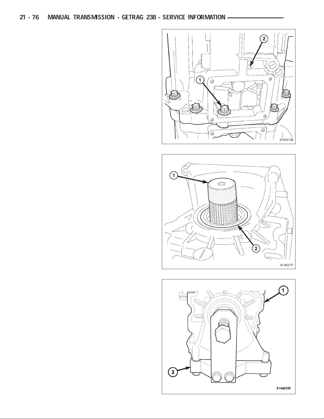
10. Place transmission on front housing and remove
rear housing (2) bolts (1). If necessary, remove
the cover plate to access the one rear housing (2)
bolt (1) located in the opening.
11. Install Button 9618-2 (1) into output shaft (2).
DR
12. Separate rear housing (1) from mainshaft with
Puller 9621(2). Bolt puller to the bottom of the
rear housing, then turn puller bolt to push mainshaft out of the housing.
Page 9
DR
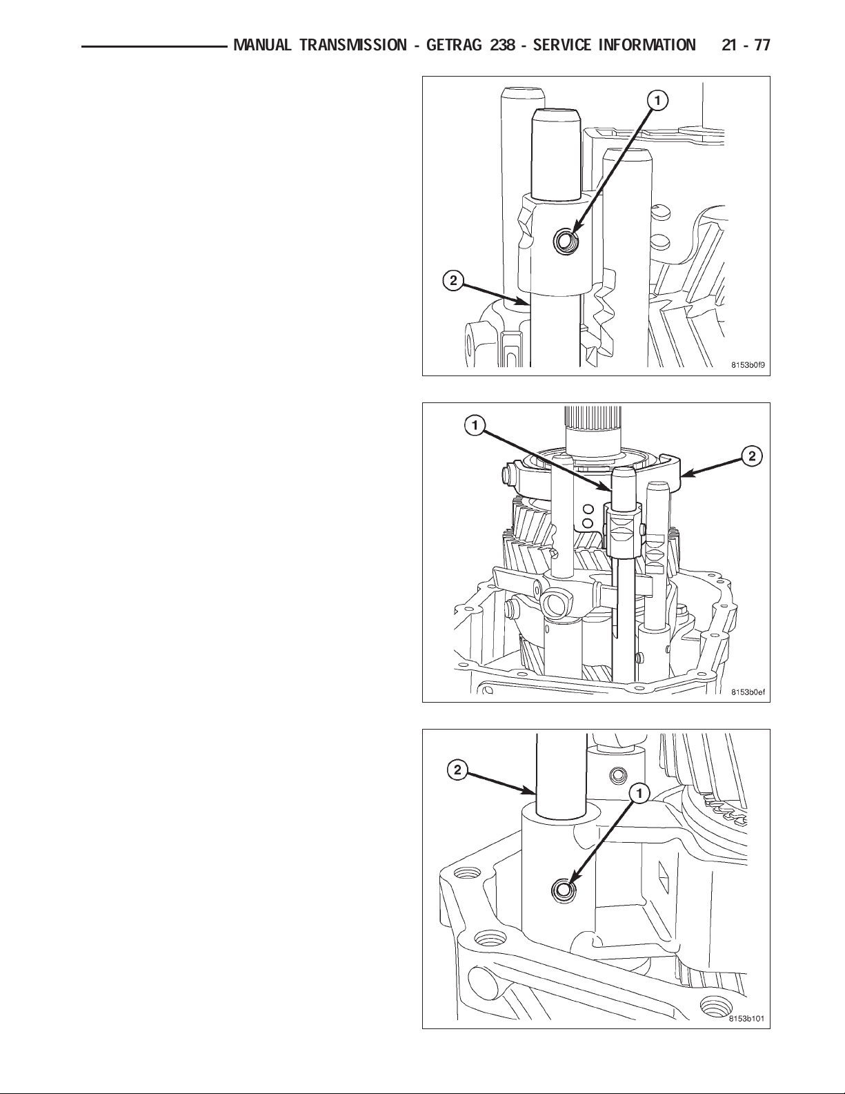
13. Remove reverse shift fork roll pin (1) from reverse
shift rail (2).
14. Slide reverse shift rail (1) down out of the shift
fork (2) and remove reverse shift fork. Then slide
shift rail up and out of the front housing.
MANUAL TRANSMISSION - GETRAG 238 - SERVICE INFORMATION 21 - 77
15. Remove 1-2 shift fork roll pin (1) from shift rail (2).
Slide shift rail up out of shift fork and rear housing. Remove 1-2 shift fork.
Page 10
21 - 78 MANUAL TRANSMISSION - GETRAG 238 - SERVICE INFORMATION
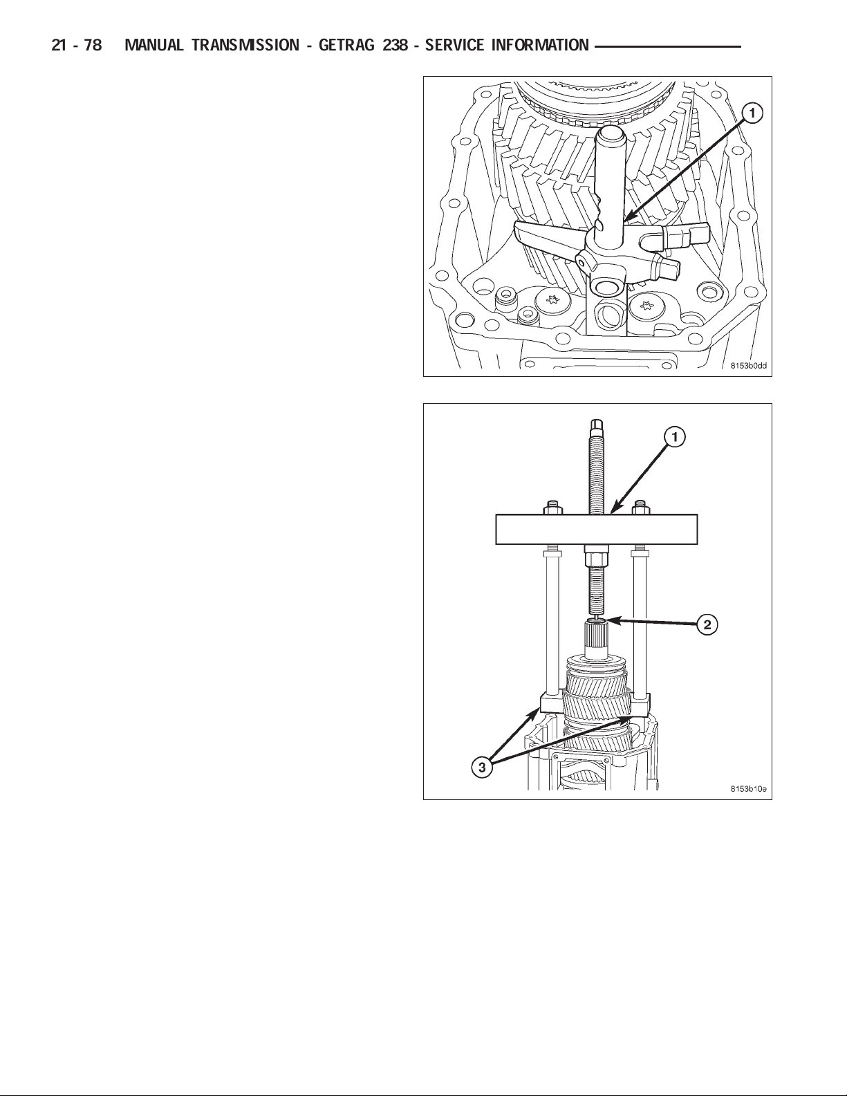
16. Rotate main shift rail (1) clockwise and pull up
and out of the front housing.
17. Remove first gear, reverse gear, reverse bearing,
reverse gear bearing race and reverse synchronizer with Bridge 938 (1), Button 9618-2 (2) and
puller Adapters 9628 (3). Position puller Adapters
9628 (3) under first gear.
DR
Page 11
DR
18. Remove first gear bearing (1) from mainshaft (2).
19. Remove first gear synchronizer inner friction ring
(1) from 1-2 synchronizer hub (2).
MANUAL TRANSMISSION - GETRAG 238 - SERVICE INFORMATION 21 - 79
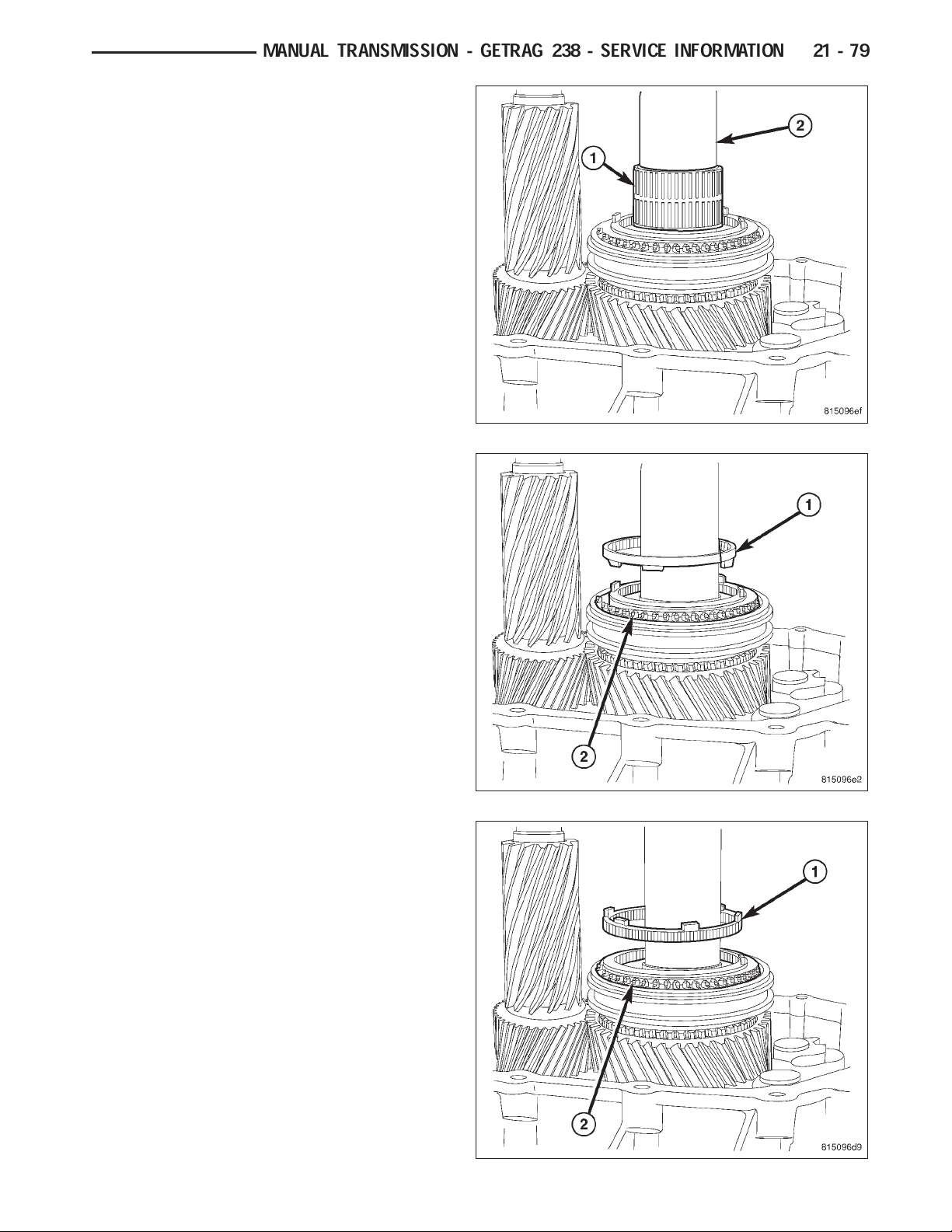
20. Remove first gear synchronizer outer friction ring
(1) from 1-2 synchronizer hub (2).
Page 12
21 - 80 MANUAL TRANSMISSION - GETRAG 238 - SERVICE INFORMATION
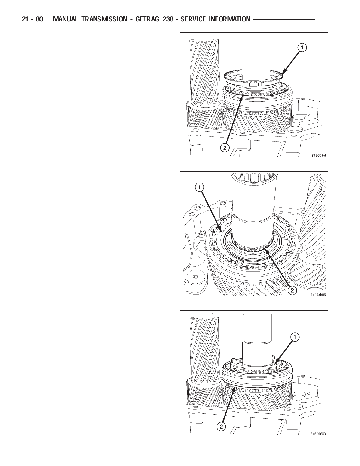
21. Remove first gear synchronizer blocker ring (1)
from 1-2 synchronizer hub (2).
22. Remove 1-2 synchronizer hub (1) snap ring (2).
DR
23. Remove 1-2 synchronizer sleeve (1) from 1-2 syn-
chronizer hub (2).
Page 13
DR
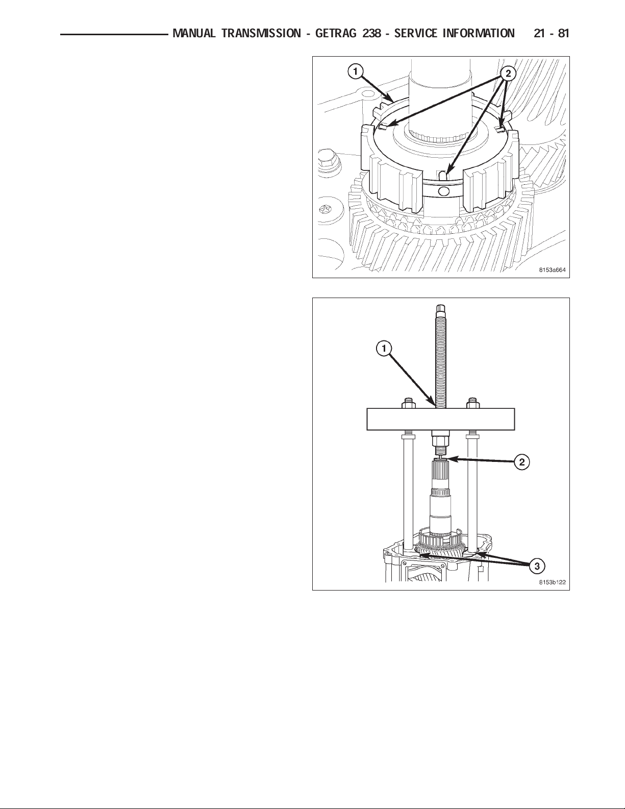
24. Remove 1-2 synchronizer hub (1) detents (2).
25. Remove second gear and 1-2 synchronizer hub
with Bridge 938 (1), Button 9618-2 (2) and Adapters 9627 (3).
MANUAL TRANSMISSION - GETRAG 238 - SERVICE INFORMATION 21 - 81
Page 14
21 - 82 MANUAL TRANSMISSION - GETRAG 238 - SERVICE INFORMATION
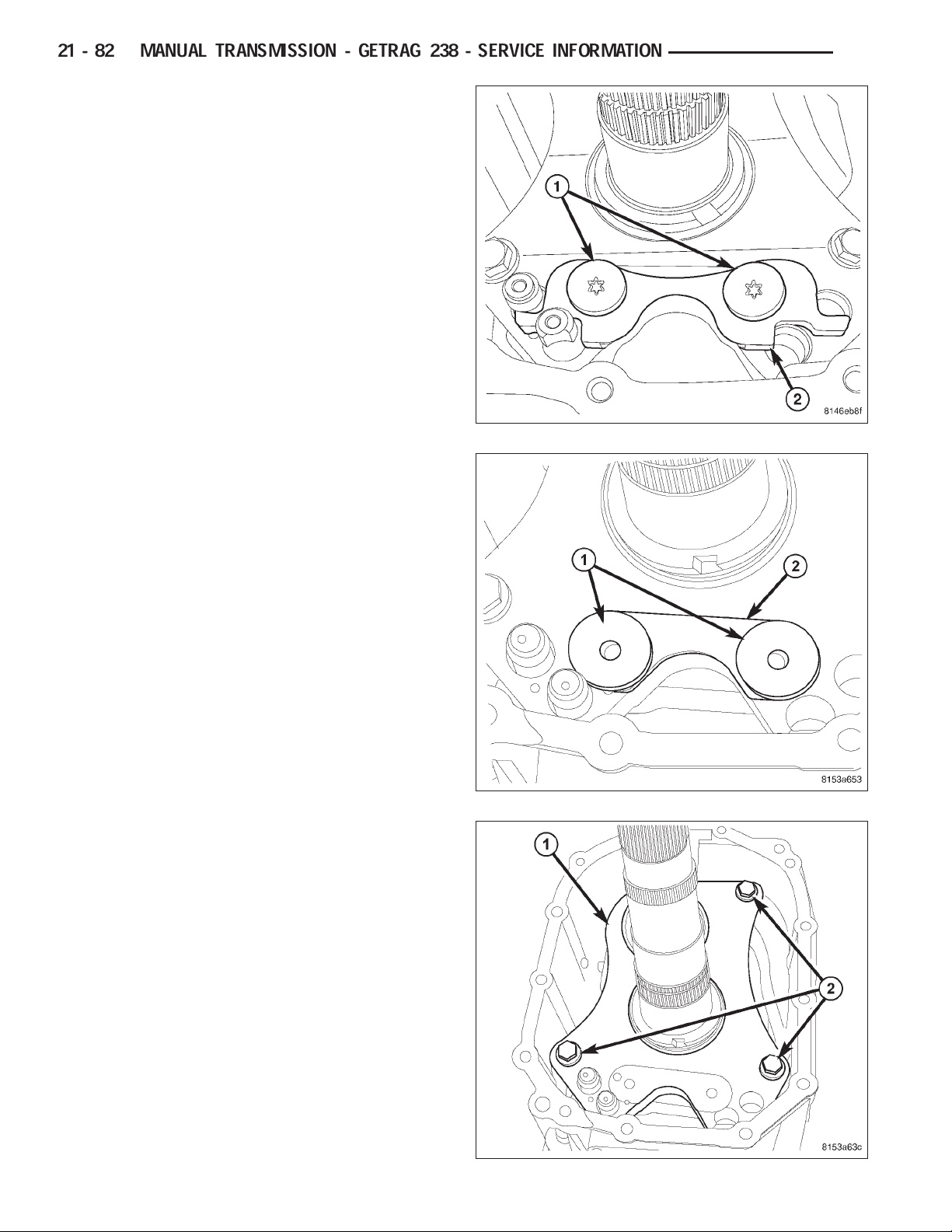
26. Remove interlock plate bolts (1) and remove inter-
lock plate (2).
27. Remove washers (1) from intermediate plate (2).
DR
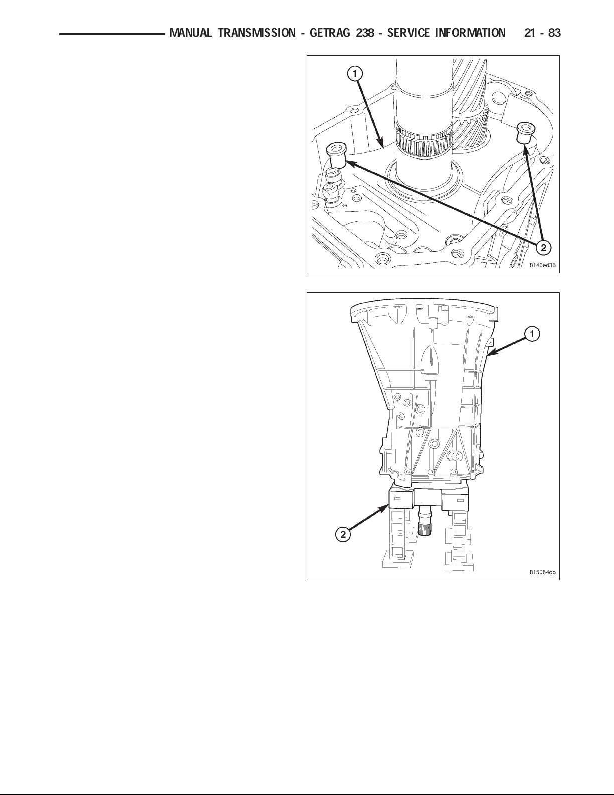
28. Remove intermediate plate (1) bolts (2).
Page 15
DR
29. Remove intermediate plate (1) dowels (2) with a
suitable tool and remove intermediate plate.
30. Install Fixture 9626 (2) on main/countershaft and
shift rails. Turn fixture (2) with transmission (1)
over onto the fixture.
MANUAL TRANSMISSION - GETRAG 238 - SERVICE INFORMATION 21 - 83
Page 16
21 - 84 MANUAL TRANSMISSION - GETRAG 238 - SERVICE INFORMATION
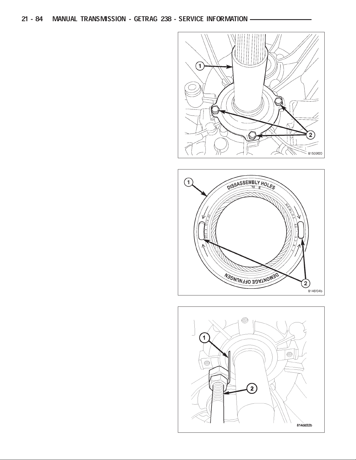
31. Remove clutch release bearing support bolts (2)
and retainer (1).
32. Insert seal Puller 9667 through one input shaft
seal (1) disassembly hole (2).
DR
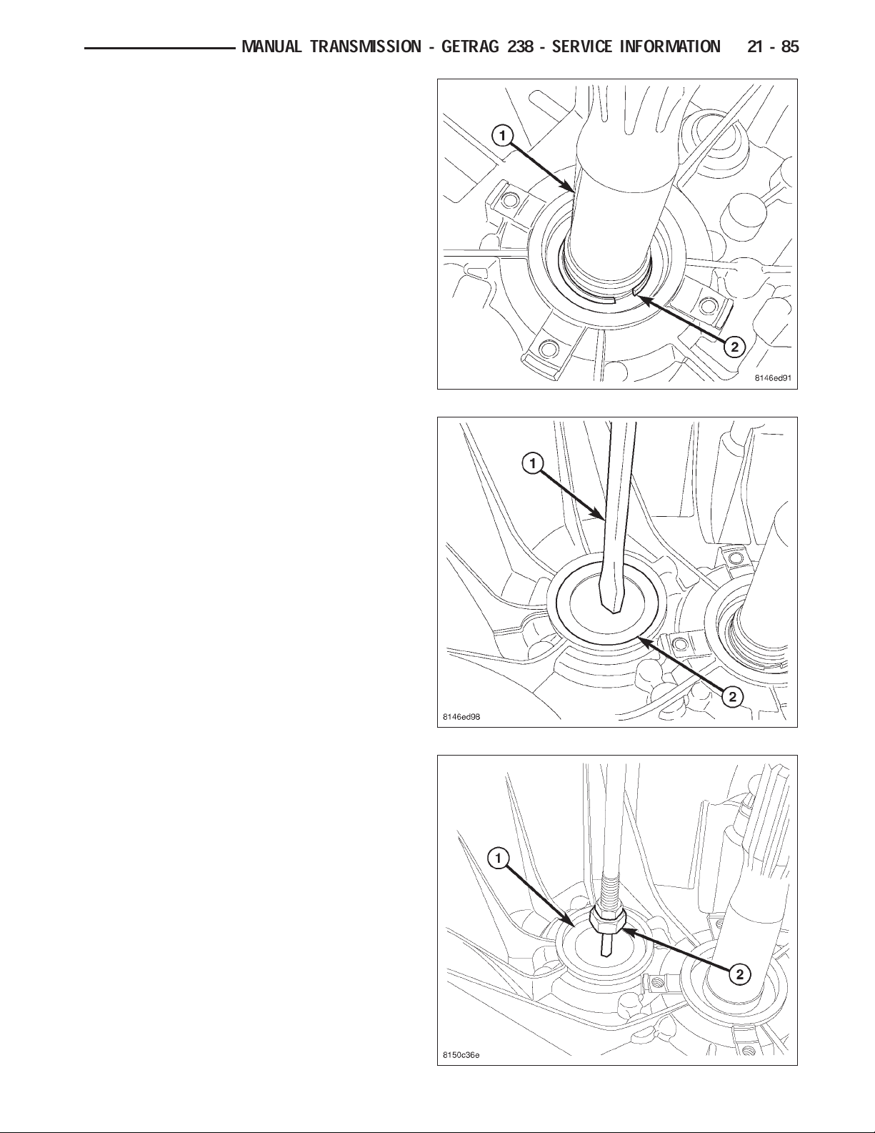
33. Remove input shaft seal with Remover 9667 (1)
and Slide Hammer C-3752 (2).
Page 17
DR
34. Remove input shaft (1) snap ring (2).
35. Put a hole in the center of the countershaft plug
(2) with a punch (1).
MANUAL TRANSMISSION - GETRAG 238 - SERVICE INFORMATION 21 - 85
36. Remove countershaft plug (1) from front housing
with Puller 9667 (2) and Slide Hammer C-3752.
Page 18

21 - 86 MANUAL TRANSMISSION - GETRAG 238 - SERVICE INFORMATION
37. Install Wrench 9586 (1) on input shaft (2).
38. Remove countershaft allen bolt (1).
39. Remove input shaft wrench.
DR
40. Remove two detent plugs from the side of the
housing with Puller 8870 (1) and Slide Hammer
C-3752 (2).
Page 19
DR
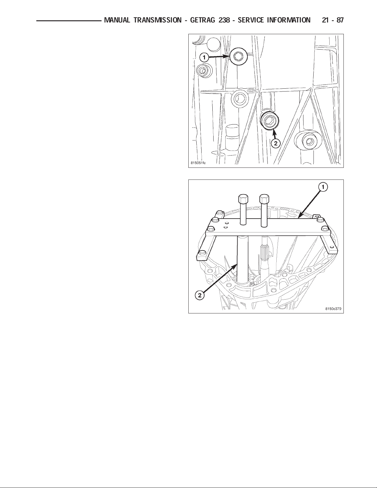
41. Remove 3-4 (2) and 5-6 (1) shift fork pivot bolts
from both sides of the front housing.
42. Install Puller 9621(1) with puller Plug 9621-2 (2)
on front housing. Tighten puller bolts evenly and
remove front housing from the mainshaft and
countershaft.
MANUAL TRANSMISSION - GETRAG 238 - SERVICE INFORMATION 21 - 87
Page 20
21 - 88 MANUAL TRANSMISSION - GETRAG 238 - SERVICE INFORMATION
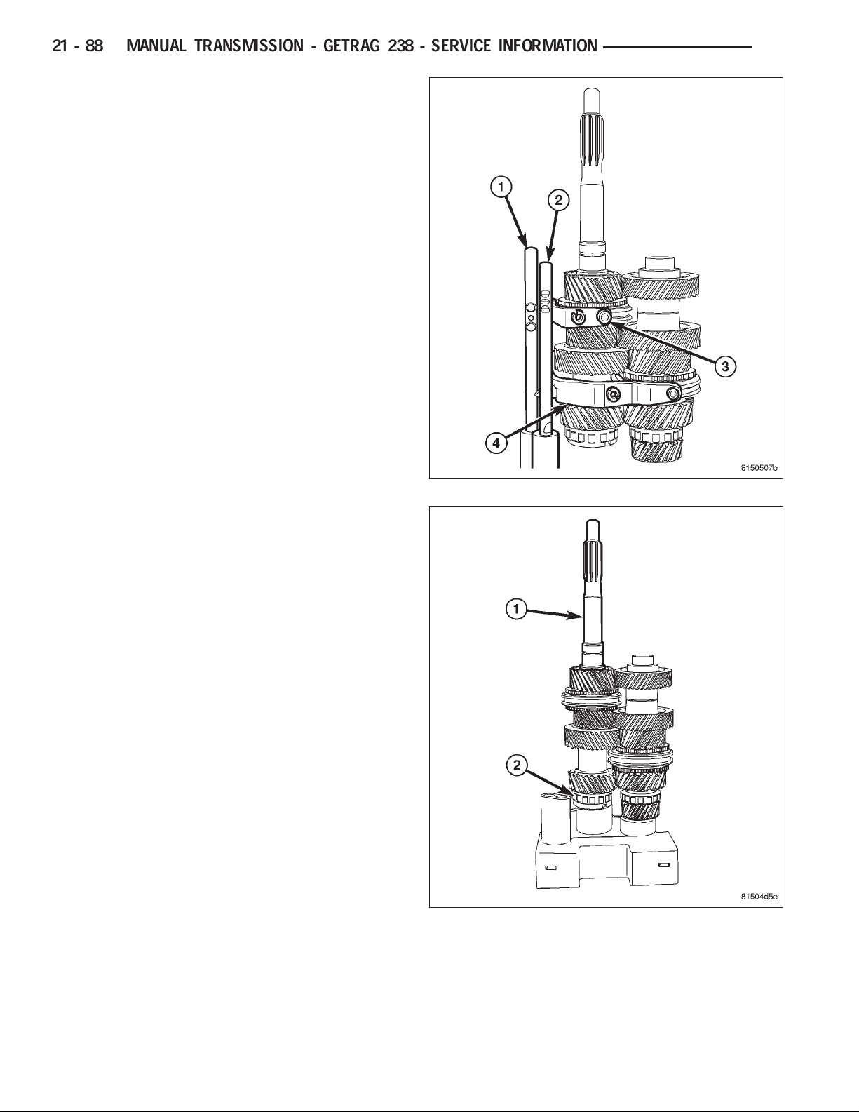
43. Remove 5-6 shift fork (3) and 3-4 shift fork (4).
Then remove 5-6 shift rail (1) and 3-4 shift rail (2)
from Fixture 9626.
DR
44. Remove input shaft (1) from mainshaft (2).
Page 21
DR
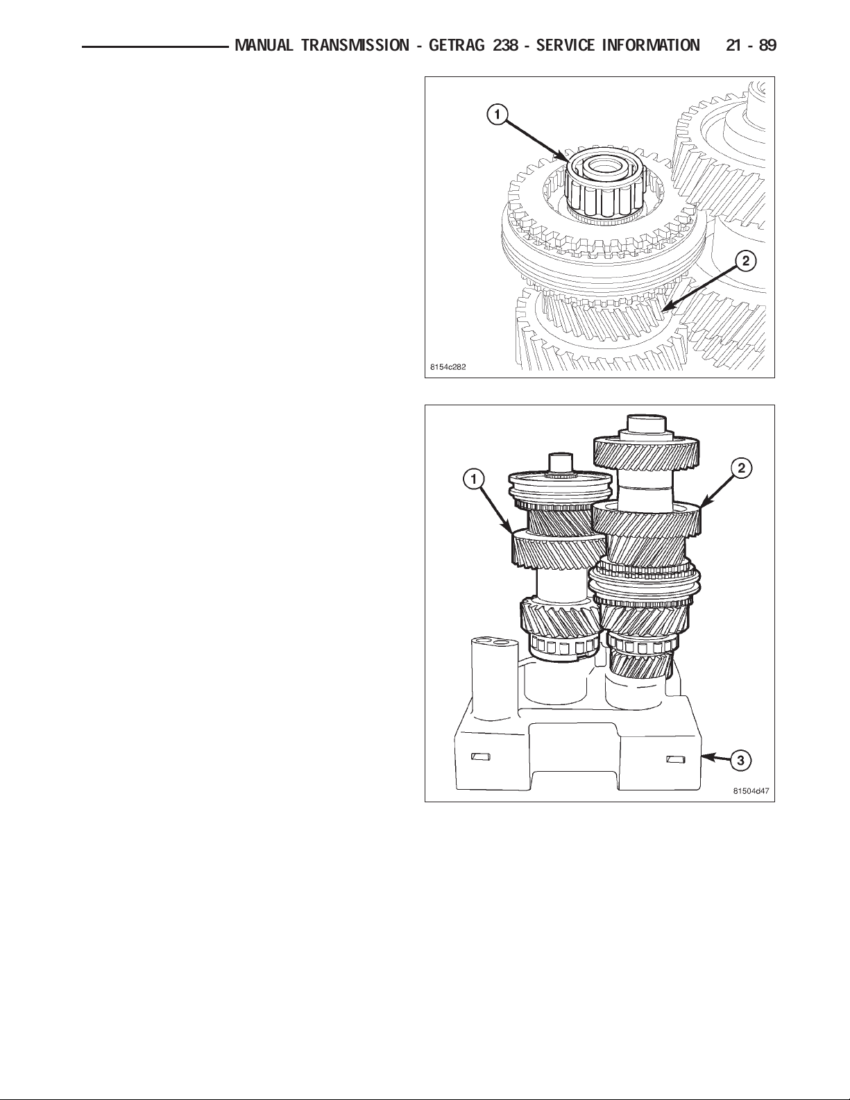
45. Remove input shaft bearing (1) from mainshaft
(2).
46. Remove countershaft (2) from fixture (3).
MANUAL TRANSMISSION - GETRAG 238 - SERVICE INFORMATION 21 - 89
Page 22
21 - 90 MANUAL TRANSMISSION - GETRAG 238 - SERVICE INFORMATION
MAINSHAFT
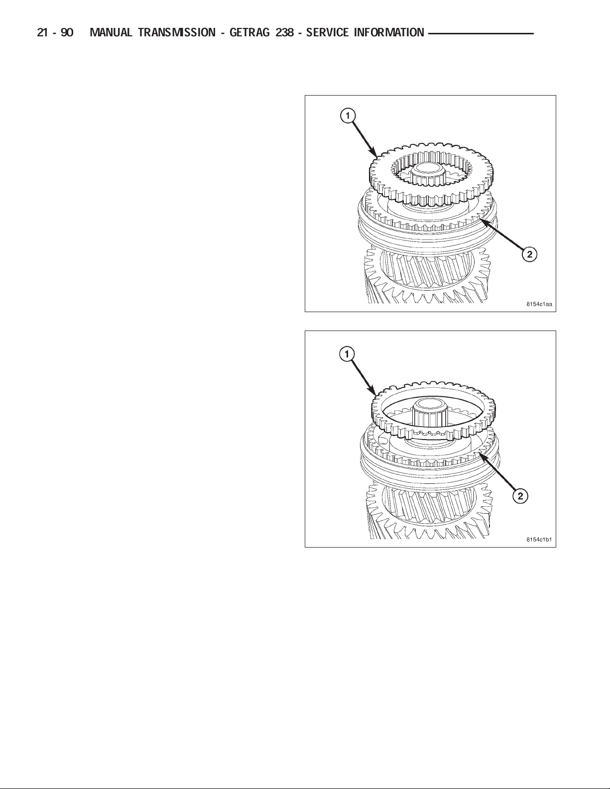
1. Remove fifth gear synchronizer clutch body (1)
from 5-6 synchronizer hub (2).
DR
2. Remove fifth gear synchronizer friction ring (1) from
5-6 synchronizer hub (2).
Page 23

DR
3. Remove 5-6 synchronizer sleeve (1) from hub (2).
4. Remove 5-6 synchronizer detents (1) from hub (2).
MANUAL TRANSMISSION - GETRAG 238 - SERVICE INFORMATION 21 - 91
5. Remove 5-6 synchronizer hub (1) snap ring (2).
Page 24

21 - 92 MANUAL TRANSMISSION - GETRAG 238 - SERVICE INFORMATION
6. Remove 5-6 synchronizer hub (1) with three jaw
puller (2) and Button 9618-2 (3). Position jaws
under sixth gear clutch body (4).
DR
7. Remove sixth gear (1) from mainshaft (2).
Page 25

DR
8. Remove sixth gear bearing (1) from mainshaft (2).
9. Remove mainshaft center support bearing (1) from
mainshaft (2).
MANUAL TRANSMISSION - GETRAG 238 - SERVICE INFORMATION 21 - 93
Page 26

21 - 94 MANUAL TRANSMISSION - GETRAG 238 - SERVICE INFORMATION
COUNTERSHAFT
1. Remove countershaft center support bearing (1)
from counter shaft (2).
NOTE: Countershaft with 3-4 synchronizer, is serviced as an assembly except bearings.
DR
CENTER SUPPORT PLATE
1. Remove center support (1) roller bearing race
retainer (2).
Page 27

DR
2. Remove mainshaft center support (1) bearing race
with Remove/Installer 9668 (2) and Handle C4171.
3. Remove countershaft center support (1) bearing
race with Remove/Installer 9617 (2) and Handle
C4171.
MANUAL TRANSMISSION - GETRAG 238 - SERVICE INFORMATION 21 - 95
Page 28

21 - 96 MANUAL TRANSMISSION - GETRAG 238 - SERVICE INFORMATION
FRONT HOUSING
1. Remove mainshaft bearing retainer (1) and countershaft bearing retainers (2).
2. Remove mainshaft bearing and countershaft bearing with hammer and driver.
DR
REAR HOUSING
1. Remove reverse idler gear shaft bolt (1) from housing (2).
Page 29

DR
2. Remove reverse idler gear shaft (1) from idler gear
(2).
3. Remove reverse idler gear (1) shaft support (2).
MANUAL TRANSMISSION - GETRAG 238 - SERVICE INFORMATION 21 - 97
4. Remove reverse idler gear (1) and bearing (2).
Page 30

21 - 98 MANUAL TRANSMISSION - GETRAG 238 - SERVICE INFORMATION
5. Remove mainshaft bearing (1) retainer (2) bolts
and remove retainer.
6. Remove bearing from housing with a hammer and
driver.
7. Break plastic countershaft roller bearing cage with
a screw driver. Then remove cage and roller bearing.
8. Insert Puller 9585 through the countershaft roller
bearing shell (1) and expand the tool (2) to grab
the bottom (3) of the bearing shell (1).
DR
9. Remove countershaft roller bearing shell (1) from
the rear housing with Puller 9585 (2) and Slide
Hammer C-637.
Page 31

DR
10. Remove shift rail roller bearing from rear housing
(3) with Puller 9609 (1) and Slide Hammer C-637
(2).
MANUAL TRANSMISSION - GETRAG 238 - SERVICE INFORMATION 21 - 99
CLEANING
Clean gears, shafts, shift components and transmission housings with a standard parts cleaning solvent. Do not use
acid or corrosive base solvents. Dry all parts except bearings with compressed air.
Clean shaft bearings with a mild solvent such as MOPART degreasing solvent, GunkT or similar solvents. Do not
dry the bearings with compressed air. Allow the bearings to either air dry or wipe them dry with clean shop towels.
INSPECTION
NOTE: Minor corrosion, nicks, or pitting can be
smoothed with 400 grit emery and polished out
with crocus cloth.
Bearings: Inspect roller bearings for wear, chips,
cracks, flat-spots or brinnelling. Inspect sealed bearings, and verify bearings roll smoothly.
Gears: Inspect for worn, chipped, or cracked teeth.
Inspect bearing surfaces for wear or flat-spots.
Mainshaft: Inspect for worn splines (1), snap ring
grooves (2) and worn, chipped or cracked teeth (3).
Inspect all bearing surfaces (4) for wear or flat-spots.
Third and fourth gear (3) are serviced with
mainshaft.
Page 32

21 - 100 MANUAL TRANSMISSION - GETRAG 238 - SERVICE INFORMATION
Countershaft: Inspect all gears for worn, chipped or
cracked teeth (1). Inspect 3-4 synchronizer assembly
for wear (2). Inspect center support bearing surfaces
(3) for wear or flat-spots. The countershaft with 3-4
synchronizer is serviced as an assembly, except
for bearings.
Synchronizer components: Inspect for worn,
chipped, or cracked teeth and burned or flaking off
friction material. Synchronizers are serviced as an
assembly.
Input Shaft: Inspect input shaft bearing (1) and bear-
ing surfaces for wear or flat-spots. Inspect input shaft
splines (2) for wear. Inspect snap ring groove (3) for
wear. Inspect fifth gear (4) for worn, chipped, or
cracked teeth.
DR
Shift forks: Inspect shift forks (1) for distortion.
Inspect fork shoes (2) for wear and fit shoes in synchronizer sleeve to ensure parts fit and work smoothly.
Page 33

DR
Shift Rails: Inspect shift rails, bushings, and bearing
for wear. Verify main shift rail (1) bearings (2) roll
smoothly.
Clutch Release Bearing Support: Inspect clutch
release bearing support (1) release bearing slide surface (2) for damage.
Housing/Tail housing: Inspect sealing and mating
surfaces are free of burrs and nicks. Inspect alignment
dowels are tight and in good condition. Inspect shift
rail bushings for wear.
MANUAL TRANSMISSION - GETRAG 238 - SERVICE INFORMATION 21 - 101
Page 34

21 - 102 MANUAL TRANSMISSION - GETRAG 238 - SERVICE INFORMATION
ASSEMBLY
MAINSHAFT
1. Install mainshaft center support bearing (1) on
mainshaft (2).
DR
2. Install sixth gear bearing (1) on mainshaft (2).
Page 35

DR
3. Install sixth gear (1) on mainshaft (2).
4. Install sixth gear clutch body (1) on sixth gear (2).
MANUAL TRANSMISSION - GETRAG 238 - SERVICE INFORMATION 21 - 103
5. Install sixth gear friction ring (1) on clutch body (2).
Page 36

21 - 104 MANUAL TRANSMISSION - GETRAG 238 - SERVICE INFORMATION
6. Install 5-6 synchronizer hub (1) on mainshaft with
Installer W-262 (2).
DR
7. Install 5-6 synchronizer hub (1) snap ring (2).
Page 37

DR
8. Install 5-6 synchronizer detents (1) in hub (2).
9. Install 5-6 synchronizer sleeve (1) on hub (2).
NOTE: Align grooves in the sleeve with detents in
hub.
MANUAL TRANSMISSION - GETRAG 238 - SERVICE INFORMATION 21 - 105
10. Install fifth gear synchronizer friction ring (1) on
5-6 synchronizer hub (2).
Page 38

21 - 106 MANUAL TRANSMISSION - GETRAG 238 - SERVICE INFORMATION
11. Install fifth gear synchronizer clutch body (1) on
5-6 synchronizer hub (2).
COUNTERSHAFT
1. Install countershaft center support bearing (1) on
countershaft (2).
DR
Page 39

DR
MANUAL TRANSMISSION - GETRAG 238 - SERVICE INFORMATION 21 - 107
CENTER SUPPORT
1. Install center support (1) countershaft roller bearing
race with Installer/Remover 9617 (2) and Handle
C-4171.
2. Install center support (1) mainshaft roller bearing
race with Installer/Remover 9668 (2) and Handle
C-4171.
Page 40

21 - 108 MANUAL TRANSMISSION - GETRAG 238 - SERVICE INFORMATION
3. Install center support (1) race retainer screw (2)
and tighten to 22 N·m (16 ft. lbs.).
REAR HOUSING
1. Install mainshaft bearing (1) in rear housing with
hammer and driver.
2. Install mainshaft bearing (1) retainer (2). Apply
MoparT Lock & Seal Adhesive or equivalent to
retainer bolts and tighten to 10 N·m (88 in. lbs.).
DR
Page 41

DR
3. Install shift rail roller bearing (1) with Installer 8475
(2).
4. Install countershaft bearing with Installer 9624 (1)
and Handle C-4171 (2).
MANUAL TRANSMISSION - GETRAG 238 - SERVICE INFORMATION 21 - 109
5. Install idler gear (1) in rear housing (2).
Page 42

21 - 110 MANUAL TRANSMISSION - GETRAG 238 - SERVICE INFORMATION
6. Install idler gear bearing (1) in idler gear (2).
7. Install idler gear (1) shaft support (2).
DR
8. Install idler gear (2) shaft (1).
Page 43

DR
9. Install shaft bolt and align idler gear shaft (1) with
shaft bolt (2).
10. Apply MoparT Lock & Seal Adhesive or equivalent
to idler shaft bolt. Tighten bolt (1) in housing (2) to
25 N·m (18 ft. lbs.).
MANUAL TRANSMISSION - GETRAG 238 - SERVICE INFORMATION 21 - 111
Page 44

21 - 112 MANUAL TRANSMISSION - GETRAG 238 - SERVICE INFORMATION
FRONT HOUSING
1. Install mainshaft and countershaft bearings in front
housing with hammer and driver.
2. Install mainshaft bearing retainer (1) and countershaft bearing retainers (2). Apply MoparT Lock &
Seal Adhesive or equivalent to retainer bolts and
tighten to 10 N·m (88 in. lbs.).
DR
3. Install mainshaft (1) and countershaft (2) in build
Fixture 9626 (3).
Page 45

DR
4. Install input shaft bearing (1) on mainshaft (2).
5. Install input shaft (1) on mainshaft (2).
MANUAL TRANSMISSION - GETRAG 238 - SERVICE INFORMATION 21 - 113
Page 46

21 - 114 MANUAL TRANSMISSION - GETRAG 238 - SERVICE INFORMATION
6. Install 5-6 shift rail (1) and 3-4 shift rail (2) in build
Fixture 9626. Then install 5-6 shift fork (3) and 3-4
shift fork (4)
DR
WARNING: Use tongs when handling heated components. Failure to follow these instructions will
result in personal injury.
CAUTION: A bearing heater (3) is used to heat
Plug 9625 (1) and Plug 9619-1 (2). Use only a bearing heater/hot plate and follow manufacture’s
instructions. Heat components to 100 - 177 Celsius (212° Min. - 350° Max Fahrenheit). Never use
an open flame to heat components. Never leave
components on heater for an extended amount of
time. If component is discolored after heating, the
component has been overheated and must not be
used. Failure to follow these instructions will
result in component damage.
7. Heat Plug 9625 (1) and Plug 9619-1 (2) to a maximum of 177 Celsius (350° Fahrenheit) with bearing
heater (3).
Page 47

DR
8. With tongs place heated Plug 9625 in countershaft
bearing and heated Plug 9619-1 into mainshaft
bearing. Allow plugs to heat bearings for two
minutes.
9. Remove Plug 9625 and Plug 9619 with welding
gloves or tongs, then install front housing (1) on
mainshaft and countershaft in fixture (2).
MANUAL TRANSMISSION - GETRAG 238 - SERVICE INFORMATION 21 - 115
Page 48

21 - 116 MANUAL TRANSMISSION - GETRAG 238 - SERVICE INFORMATION
10. Apply MoparT Lock & Seal Adhesive or equivalent
to shift fork pivot bolts. Install 5-6 (1) and 3-4 (2)
shift fork pivot bolts, in both sides of the front
housing and tighten to 35 N·m (26 ft. lbs.).
NOTE: Verify shift fork pivot holes are aligned with
pivot bolt holes before installing bolts.
11. Install two detents (1) in the side of the front hous-
ing (2).
DR
Page 49

DR
MANUAL TRANSMISSION - GETRAG 238 - SERVICE INFORMATION 21 - 117
FINAL ASSEMBLY
1. Turn front housing (1) with fixture (2) over onto the
front housing and remove fixture.
2. Install intermediate plate (1) and two dowels (2).
Page 50

21 - 118 MANUAL TRANSMISSION - GETRAG 238 - SERVICE INFORMATION
3. Install intermediate plate (1) bolts (2) and tighten to
22 N·m (16 ft. lbs.).
4. Install interlock plate washers (1) on support (2).
DR
5. Install interlock plate (2) and tighten bolts (1) to 10
N·m (88 in. lbs.).
Page 51

DR
6. Install second gear bearing (1) on mainshaft (2).
7. Install second gear (1) on mainshaft (2).
MANUAL TRANSMISSION - GETRAG 238 - SERVICE INFORMATION 21 - 119
8. Install second gear inner friction ring (1) on second
gear (2).
Page 52

21 - 120 MANUAL TRANSMISSION - GETRAG 238 - SERVICE INFORMATION
9. Install second gear outer friction ring (1) on second
gear (2).
10. Install second gear blocker ring (1) on second
gear (2).
DR
Page 53

DR
11. Align 1-2 synchronizer hub (1) with blocker ring on
mainshaft and install hub with Installer D-389 (2).
NOTE: If 1-2 synchronizer hub is installed incorrectly the snap ring groove will not be visible.
MANUAL TRANSMISSION - GETRAG 238 - SERVICE INFORMATION 21 - 121
12. Install 1-2 synchronizer hub (1) snap ring (2).
Page 54

21 - 122 MANUAL TRANSMISSION - GETRAG 238 - SERVICE INFORMATION
13. Install 1-2 synchronizer hub (1) detents (2).
14. Install 1-2 synchronizer sleeve (2) on 1-2 hub (1).
NOTE: Align grooves in the sleeve with detents in
hub.
DR
15. Install first gear blocker ring (1) on 1-2 hub (2).
Page 55

DR
16. Install first gear outer friction ring (1) on 1-2 hub
(2).
17. Install first gear inner friction ring (1) on 1-2 hub
(2).
MANUAL TRANSMISSION - GETRAG 238 - SERVICE INFORMATION 21 - 123
18. Install first gear bearing (1) on mainshaft (2).
Page 56

21 - 124 MANUAL TRANSMISSION - GETRAG 238 - SERVICE INFORMATION
19. Install first gear (1) on mainshaft (2).
WARNING: Use welding gloves or tongs when
handling heated components. Failure to follow
these instructions will result in personal injury.
DR
CAUTION: A bearing heater is used to heat reverse
bearing race (1). Use only a bearing heater/hot
plate and follow manufacturer’s instructions. Heat
components to 100 - 177 Celsius (212° Min. - 350°
Max Fahrenheit). Never use an open flame to heat
components. Never leave components on heater
for an extended amount of time. If component is
discolored after heating, the component has been
overheated and must not be used. Failure to follow these instructions will result in component
damage.
20. Heat reverse bearing race (1) with bearing heater
(2) to a maximum of 177 Celsius (350°
Fahrenheit).
21. With welding gloves or tongs install reverse bear-
ing race (1) on mainshaft (2).
Page 57

DR
22. Install reverse gear bearing (1) on bearing race
(2).
23. Install reverse gear (1) on mainshaft (2).
MANUAL TRANSMISSION - GETRAG 238 - SERVICE INFORMATION 21 - 125
24. Install reverse gear friction/blocker ring (1) on
reverse gear (2).
Page 58

21 - 126 MANUAL TRANSMISSION - GETRAG 238 - SERVICE INFORMATION
25. Install reverse synchronizer detents (1) in reverse
hub (2).
26. Install reverse synchronizer sleeve (1) on reverse
hub (2).
NOTE: Align grooves in the sleeve with detents in
hub.
DR
27. Install reverse gear synchronizer hub (1) with
Installer D-389 (2).
Page 59

DR
28. Install main shift rail (1) bearings (2) on main shift
rail.
29. Install main shift rail (1) through rail support (2)
and housing, then rotate counterclockwise into
place.
MANUAL TRANSMISSION - GETRAG 238 - SERVICE INFORMATION 21 - 127
30. Install 1-2 shift fork then, install 1-2 shift rail (2)
into shift fork and housing. Install shift fork roll pin
(1).
Page 60

21 - 128 MANUAL TRANSMISSION - GETRAG 238 - SERVICE INFORMATION
31. Install reverse shift rail (1) into the housing. Then
install reverse shift fork (2) and pull shift rail (1)
up into the shift fork.
32. Install reverse shift fork roll pin (1).
DR
WARNING: Use tongs when handling heated components. Failure to follow these instructions will
result in personal injury.
CAUTION: A bearing heater (2) is used to heat
Plug 9619-2 (1). Use only a bearing heater/hot
plate and follow manufacturer’s instructions. Heat
components to 100 - 177 Celsius (212° Min. - 350°
Max Fahrenheit). Never use an open flame to heat
components. Never leave components on heater
for an extended amount of time. If component is
discolored after heating, the component has been
overheated and must not be used. Failure to follow these instructions will result in component
damage.
33. Heat Plug 9619-2 (1) with bearing heater (2) to a
maximum of 177 Celsius (350° Fahrenheit).
Page 61

DR
34. With tongs place Plug 9619-2 in rear housing
mainshaft bearing (2). Allow plug to heat bearing
for two minutes.
35. Apply a bead of MoparT Gasket Maker or equiv-
alent to the front housing sealing surface.
36. Remove plug and install rear housing (1) on front
housing (2).
37. Install housing bolts and tighten to 22 N·m (16 ft.
lbs.).
MANUAL TRANSMISSION - GETRAG 238 - SERVICE INFORMATION 21 - 129
38. Install output shaft seal in rear housing (1) with
Installer 9629 (2).
Page 62

21 - 130 MANUAL TRANSMISSION - GETRAG 238 - SERVICE INFORMATION
39. Install 4x4 transmission output shaft nut with
Socket 9584 and tighten to 200 N·m (147 ft. lbs.).
Then loosen nut and tighten to 170 N·m (125 ft.
lbs.).
40. Drive output shaft flange onto the output shaft
with Installer D-389.
41. Install 4x2 transmission output shaft flange (1)
and tighten bolt (2) to 200 N·m (147 ft. lbs.). Then
loosen bolt and tighten to 170 N·m (125 ft. lbs.).
Remove Wrench 9586 from input shaft.
DR
42. Install two detent plugs in the top of the rear
housing.
43. Install large detent plunger (1) and spring (2) in
the side of the rear housing.
Page 63

DR
44. Install large detent plug (1) in the side of the rear
housing (2).
45. Install back up lamp switch (1) and tighten bolt (2)
to 10 N·m (88 in. lbs.). Then lay transmission
down on bench.
MANUAL TRANSMISSION - GETRAG 238 - SERVICE INFORMATION 21 - 131
46. Install input shaft (1) snap ring (2).
Page 64

21 - 132 MANUAL TRANSMISSION - GETRAG 238 - SERVICE INFORMATION
47. Install input shaft seal in front housing with
Installer 9620 (1) and Tube C-3717 (2).
48. Install clutch bearing release support (1) and
tighten bolts (2) to 10 N·m (88 in. lbs.).
DR
49. Install Wrench 9586 (1) on input shaft (2).
Page 65

DR
50. Install countershaft bolt (1) in front housing.
Tighten bolt (1) to 90 N·m (66 ft. lbs.).
51. Install countershaft plug in front housing (1) with
Installer 9622 (2) and Handle C-4171.
MANUAL TRANSMISSION - GETRAG 238 - SERVICE INFORMATION 21 - 133
52. Install the cover plate for the second shift tower
location, if necessary.
53. Apply MoparT Lock & Seal or equivalent to shifter
socket threads and install shifter socket (1).
Page 66

21 - 134 MANUAL TRANSMISSION - GETRAG 238 - SERVICE INFORMATION
INSTALLATION
1. Clean transmission front housing mounting surface.
2. Apply light coat of Mopar high temperature bearing
grease or equivalent to contact surfaces of following components:
• release fork (1) ball stud (2)
• release bearing slide surface (3)
• input shaft splines (4)
• release bearing bore (5)
• propeller shaft slip yoke.
3. Support and secure transmission to jack.
4. Raise and align transmission input shaft with clutch
disc, then slide transmission into place.
5. Verify front housing is fully seated. Install transmission bolts without washers (1) and tighten bolts into
the engine to 41 N·m (30 ft. lbs.). Tighten the bolts
with washers (2) into the transmission to 68 N·m
(50 ft. lbs.).
6. Install rear crossmember (1) and tighten nuts to
102 N·m (75 ft. lbs.).
7. Install transmission rear mount (2) bolts and tighten
to 68 N·m (50 ft. lbs.).
DR
Page 67

DR
8. Install front dust shield (1) tighten bolt to 4.5 N·m
(40 in. lbs.).
9. Install structural cover (3) to transmission bolts and
tighten to 54 N·m (40 ft. lbs.).
10. Install starter motor (2).
11. Install suspension crossmember (4) and tighten
nuts to 102 N·m (75 ft. lbs.).
12. Connect transmission harnesses to clips on case
and connect switches.
13. Install slave cylinder (2) and tighten cylinder nuts
(1) to 23 N·m (200 in. lbs.).
14. Install transfer case and transfer case linkage if
equipped.
15. Remove transmission jack.
16. Install propeller shaft/shafts with reference marks
aligned.
17. Install exhaust on the exhaust manifolds.
18. Fill transmission with lubricant. Correct fill level is
to bottom edge of fill plug hole.
MANUAL TRANSMISSION - GETRAG 238 - SERVICE INFORMATION 21 - 135
SPECIFICATIONS
MANUAL TRANSMISSION - GETRAG 238
TORQUE SPECIFICATIONS
DESCRIPTION N·m Ft. Lbs. In. Lbs.
Drain Plug 50 37 -
Fill Plug 50 37 -
Shift Tower Bolts 10 - 88
Back Up Lamp Switch Bolt 10 - 88
4x2 Output Flange Bolt
4x4 Output Shaft Nut
Housing Bolts 22 16 -
Interlock Plate Bolts 10 - 88
Intermediate Support Bolts 22 16 -
Intermediate Support Race
Retainer Bolt
Countershaft Bolt 90 66 -
200 then loosen and
tighten to 170
200 then loosen and
tighten to 170
22 16 -
147 then loosen and
tighten to 125
147 then loosen and
tighten to 125
-
-
Page 68

21 - 136 MANUAL TRANSMISSION - GETRAG 238 - SERVICE INFORMATION
DESCRIPTION N·m Ft. Lbs. In. Lbs.
Reverse Idler Gear Shaft
Bolt
Mainshaft, Countershaft
Bearing Retainer Bolts
Input Shaft Retainer Bolts 10 - 88
Shift Fork Pivot Bolts 35 26 -
Support Braket to Trans
Bolts
GEAR SPECIFICATIONS
GEAR RATIO
FIRST 4.23
SECOND 2.53
THIRD 1.67
FOURTH 1.23
FIFTH 1.00
SIXTH 0.79
REVERSE 3.84
25 18 -
10 - 88
54 40 -
DR
Page 69

DR
SPECIAL TOOLS
INSTALLER C-3717
MANUAL TRANSMISSION - GETRAG 238 - SERVICE INFORMATION 21 - 137
INSTALLER W-262
SLIDE HAMMER C-3752
SLIDE HAMMER C-637
INSTALLER 8475
PULLER 8870
INSTALLER D-389
PULLER 8992
Page 70

21 - 138 MANUAL TRANSMISSION - GETRAG 238 - SERVICE INFORMATION
DR
BRIDGE 938
PULLER 9583
WRENCH 9586
PULLER 9609
SOCKET 9584
PULLER 9585
REMOVER/INSTALLER 9617
PULLER 9618
Page 71

DR
MANUAL TRANSMISSION - GETRAG 238 - SERVICE INFORMATION 21 - 139
BUTTON 9618-2
HEAT PLUG 9619-1 & 9619-2
INSTALLER 9622
INSTALLER 9624
INSTALLER 9620
PULLER 9621
HEAT PLUG 9625
FIXTURE 9626
Page 72

21 - 140 MANUAL TRANSMISSION - GETRAG 238 - SERVICE INFORMATION
DR
PULLER ADAPTER 9627
PULLER ADAPTER 9628
REMOVER/INSTALLER 9668
INSTALLER 9629
REMOVER 9667
 Loading...