

Page 1

DR FUEL SYSTEM 14 - 1
FUEL SYSTEM
TABLE OF CONTENTS
page page
FUEL DELIVERY - GAS ....................1
FUEL INJECTION - GAS ...................44
FUEL DELIVERY - GAS
TABLE OF CONTENTS
page page
FUEL DELIVERY - GAS
DESCRIPTION .................................2
OPERATION ...................................4
STANDARD PROCEDURE
STANDARD PROCEDURE - FUEL SYSTEM
PRESSURE RELEASE........................4
STANDARD PROCEDURE - DRAINING FUEL
TANK - EXCEPT DIESEL......................5
SPECIFICATIONS
FUEL SYSTEM PRESSURE ...................5
TORQUE - EXCEPT DIESEL ..................5
SPECIAL TOOLS
FUEL SYSTEM ..............................8
FUEL FILTER/PRESSURE REGULATOR
DESCRIPTION .................................9
OPERATION ...................................9
SENSOR - FUEL LEVEL SENDING UNIT
DESCRIPTION ................................10
OPERATION ..................................10
REMOVAL ....................................10
INSTALLATION ................................11
LINES, FUEL
DESCRIPTION ................................12
FITTING-QUICK CONNECT
DESCRIPTION ................................13
STANDARD PROCEDURE - QUICK-CONNECT
FITTINGS ..................................13
MODULE-FUEL PUMP
DESCRIPTION ................................19
FUEL DELIVERY - DIESEL ................104
FUEL INJECTION - DIESEL ...............140
OPERATION ..................................19
MODULE - FUEL PUMP
DESCRIPTION ................................20
OPERATION ..................................20
REMOVAL ....................................20
INSTALLATION ...............................21
RAIL - FUEL
DESCRIPTION ................................22
OPERATION ..................................22
REMOVAL
3.7L V-6 ....................................22
4.7L V-8 ....................................23
5.7L .......................................24
8.3L - SRT-10 ...............................26
INSTALLATION
3.7L .......................................30
4.7L .......................................31
5.7L .......................................32
8.3L - SRT-10 ...............................32
TANK - FUEL
DESCRIPTION ................................34
OPERATION ..................................34
REMOVAL- EXCEPT DIESEL ...................34
INSTALLATION - EXCEPT DIESEL ..............38
FILTER - INLET
REMOVAL ....................................43
INSTALLATION ...............................43
Page 2
14 - 2 FUEL DELIVERY - GAS DR
FUEL DELIVERY - GAS
DESCRIPTION
The fuel delivery system consists of:
• a fuel pump module containing the electric fuel pump, fuel filter/fuel pressure regulator, fuel gauge sending unit
(fuel level sensor) and a secondary fuel filter located at the bottom of the pump module
• fuel tubes/lines/hoses
• a combination fuel filter/fuel pressure regulator
• quick-connect fittings
• fuel injector rail
• fuel tank
• fuel tank filler/vent tube assembly
• fuel tank filler tube cap
• accelerator pedal
• throttle cable
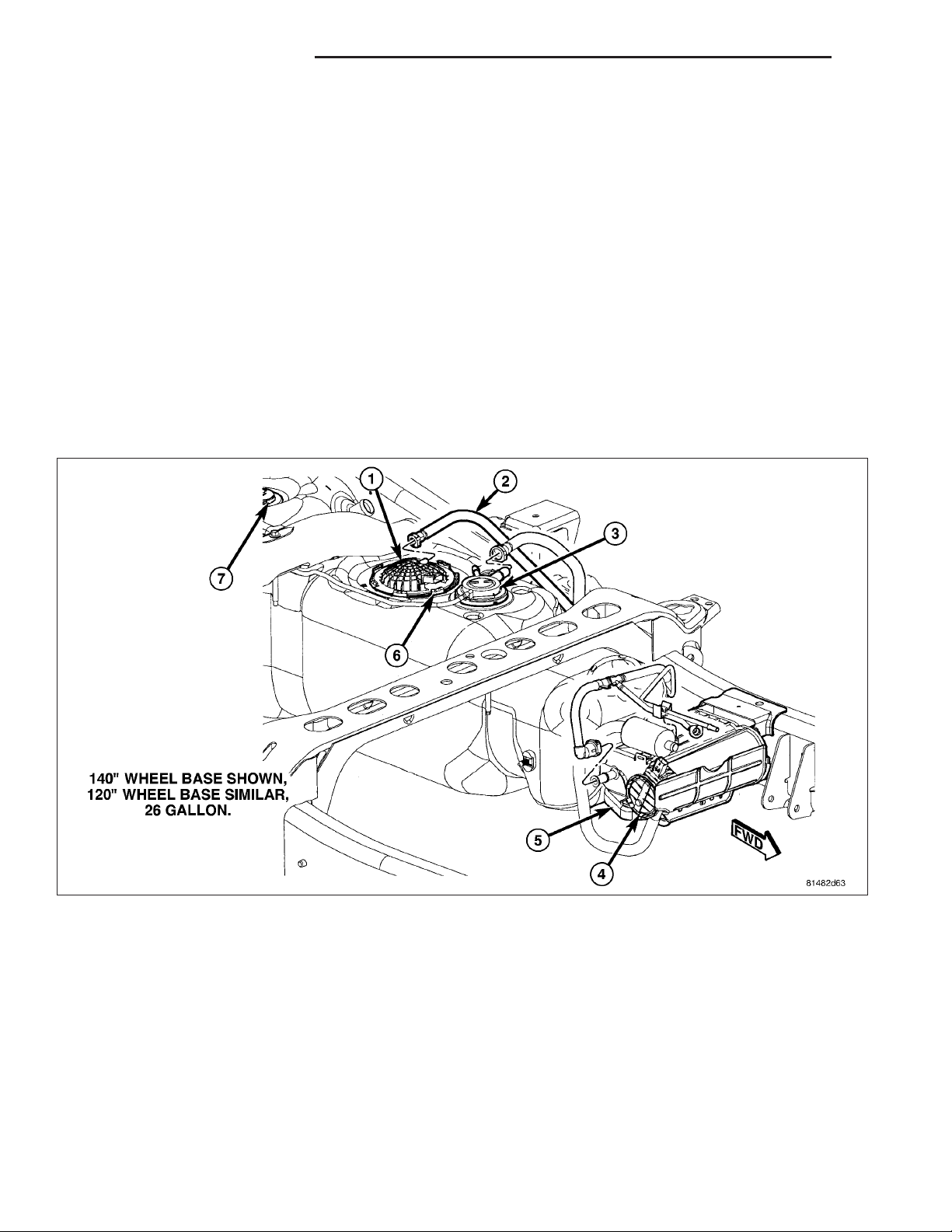
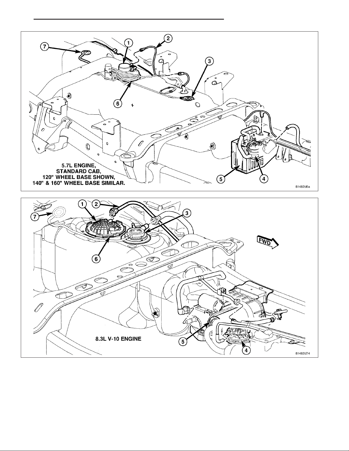
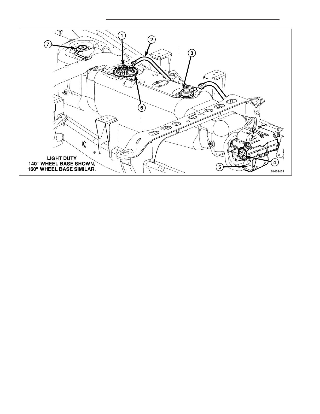
Certain fuel delivery components can be found in the following graphics:
Page 3
DR FUEL DELIVERY - GAS 14 - 3
Page 4
14 - 4 FUEL DELIVERY - GAS DR
OPERATION
Fuel is returned through the fuel pump module and back into the fuel tank through the fuel filter/fuel pressure regulator. A separate fuel return line from the engine to the tank is not used.
The fuel tank assembly consists of: the fuel tank, fuel pump module assembly, fuel pump module locknut/gasket,
and fuel tank check valve (refer to Fuel Tank Check Valve for information).
A fuel filler/vent tube assembly using a pressure/vacuum, 1/4 turn fuel filler cap is used. The fuel filler tube contains
a flap door located below the fuel fill cap.
Also to be considered part of the fuel system is the evaporation control system. This is designed to reduce the
emission of fuel vapors into the atmosphere. The description and function of the Evaporative Control System is
found in Emission Control Systems.
Both fuel filters (at bottom of fuel pump module and within fuel pressure regulator) are designed for extended service. They do not require normal scheduled maintenance. Filters should only be replaced if a diagnostic procedure
indicates to do so.
STANDARD PROCEDURE
STANDARD PROCEDURE - FUEL SYSTEM PRESSURE RELEASE
Use following procedure if the fuel injector rail is, or is not equipped with a fuel pressure test port.
1. Remove fuel fill cap.
2. Remove fuel pump relay from Power Distribution Center (PDC). For location of relay, refer to label on underside
of PDC cover.
3. Start and run engine until it stalls.
4. Attempt restarting engine until it will no longer run.
5. Turn ignition key to OFF position.
CAUTION: Steps 1, 2, 3 and 4 must be performed to relieve high pressure fuel from within fuel rail. Do not
attempt to use following steps to relieve this pressure as excessive fuel will be forced into a cylinder chamber.
6. Unplug connector from any fuel injector.
7. Attach one end of a jumper wire with alligator clips (18 gauge or smaller) to either injector terminal.
Page 5

DR FUEL DELIVERY - GAS 14 - 5
8. Connect other end of jumper wire to positive side of battery.
9. Connect one end of a second jumper wire to remaining injector terminal.
CAUTION: Powering an injector for more than a few seconds will permanently damage the injector.
10. Momentarily touch other end of jumper wire to negative terminal of battery for no more than a few seconds.
11. Place a rag or towel below fuel line quick-connect fitting at fuel rail.
12. Disconnect quick-connect fitting at fuel rail. Refer to Quick-Connect Fittings.
13. Return fuel pump relay to PDC.
14. One or more Diagnostic Trouble Codes (DTC’s) may have been stored in PCM memory due to fuel pump relay
removal. The DRBT scan tool must be used to erase a DTC.
STANDARD PROCEDURE - DRAINING FUEL TANK - EXCEPT DIESEL
WARNING: The fuel system may be under constant fuel pressure even with the engine off. This pressure
must be released before servicing fuel tank.
Two different procedures may be used to drain fuel tank: through the fuel fill fitting on tank, or using a diagnostic
scan tool to activate the fuel pump relay. Due to a one-way check valve installed into the fuel fill opening fitting at
the tank, the tank cannot be drained conventionally at the fill cap.
The quickest draining procedure involves removing the rubber fuel fill hose at the fuel tank.
As an alternative procedure, the electric fuel pump may be activated allowing tank to be drained at fuel rail con-
nection. Refer to diagnostic scan tool for fuel pump activation procedures. Before disconnecting fuel line at fuel rail,
release fuel pressure. Refer to the Fuel System Pressure Release Procedure for procedures. Attach end of special
test hose tool number 6631 or 6539 at fuel rail disconnection (tool number 6631 is used on 5/16” fuel lines while
tool number 6539 is used on 3/8” fuel lines). Position opposite end of this hose tool to an approved gasoline draining station. Activate fuel pump and drain tank until empty.
If electric fuel pump is not operating, fuel must be drained through fuel fill fitting at tank. Refer to following procedures.
1. Release fuel system pressure.
2. Raise vehicle.
3. Thoroughly clean area around fuel fill fitting and rubber fuel fill hose at tank.
4. If vehicle is equipped with 4 doors and a 6 foot (short) box, remove left-rear tire/wheel.
5. Loosen clamp and disconnect rubber fuel fill hose at tank fitting. Using an approved gas holding tank, drain fuel
tank through this fitting.
SPECIFICATIONS
FUEL SYSTEM PRESSURE
58 psi +/- 2 psi
TORQUE - EXCEPT DIESEL
DESCRIPTION N-m Ft. Lbs. In. Lbs.
Accelerator Pedal Bracket
Mounting
Accelerator Pedal Position
Sensor Bracket-to-Battery
Tray Bolts
Crankshaft Position
Sensor - 3.7L
Crankshaft Position
Sensor - 4.7L
12 - 105
3-30
28 21 -
28 21 -
Page 6

14 - 6 FUEL DELIVERY - GAS DR
DESCRIPTION N-m Ft. Lbs. In. Lbs.
Crankshaft Position
Sensor - 5.7L
Camshaft Position Sensor
- 3.7L
Camshaft Position Sensor
- 4.7L
Camshaft Position Sensor
- 5.7L
Engine Coolant
Temperature Sensor - 3.7L
Engine Coolant
Temperature Sensor - 4.7L
Engine Coolant
Temperature Sensor - 5.7L
EVAP Canister- to-Bracket
Nuts
EVAP Canister-to-Frame
Bolts
Fuel Filler Hose Clamp at
Tank
Fuel Filler Housing-to-
Body Screws
Fuel Pump Module Lock
Ring
Fuel Rail Mounting Bolts -
3.7L
Fuel Rail Mounting Bolts -
4.7L
Fuel Rail Mounting Bolts -
5.7L
Fuel Rail Mounting Bolts -
8.3L
Fuel Tank Mounting Straps 41 30 -
IAC Motor Mounting
Screws - 3.7L
IAC Motor Mounting
Screws - 4.7L
Leak Detection Pump
Mounting Bolt
Map Sensor Mounting
Screws - 3.7L
Map Sensor Mounting
Screws - 4.7L
PCM-to-Mounting Bracket
Mounting Screws
Power Steering Pressure
Switch - 3.7L
Power Steering Pressure
Switch - 4.7L
12 - 105 (+/-20)
12 - 106
12 - 106
12 9 105 (+/-) 20
11 - 96
11 - 96
11 - 96
8.5 - 75
34 25
3-30
2-17
54 40 -
11 -
11 - 100
11 - 100
12 - 105
7-60
7-60
8.5 - 75
3-25
3-25
4-35
14-22 - 124-195
14-22 - 124-195
100
Page 7

DR FUEL DELIVERY - GAS 14 - 7
DESCRIPTION N-m Ft. Lbs. In. Lbs.
TPS Mounting Screws -
3.7L
TPS Mounting Screws -
4.7L
Throttle Body Mounting
Bolts - 3.7L
Throttle Body Mounting
Bolts - 4.7L
Throttle Body Mounting
Bolts - 5.7L
Oxygen Sensors 30 22 -
Ignition Coil Mounting
Bolts
7-60
7-60
11 - 100
12 - 105
12 - 105
11 - 100
Page 8
14 - 8 FUEL DELIVERY - GAS DR
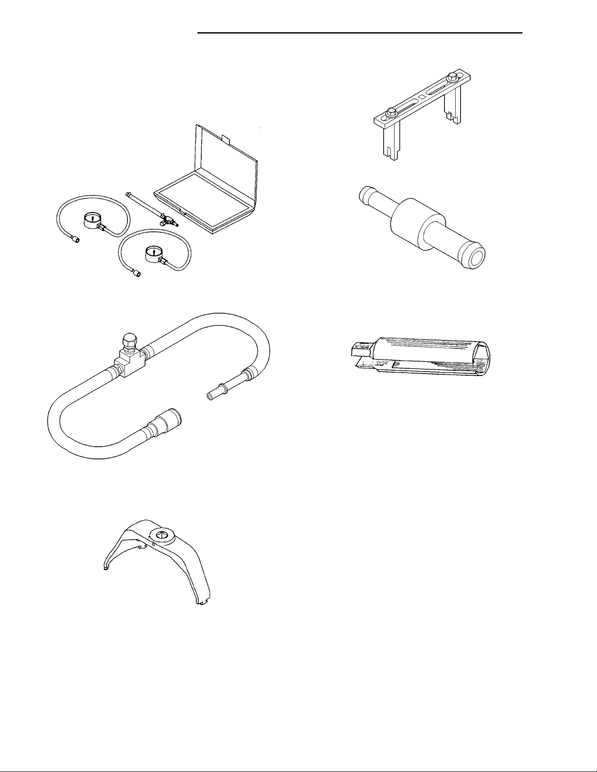
SPECIAL TOOLS
FUEL SYSTEM
SPANNER WRENCH - #6856
TEST KIT, FUEL PRESSURE #5069
ADAPTERS, FUEL PRESSURE TEST - #6539
AND/OR #6631
FITTING, AIR METERING - #6714
O2S (OXYGEN SENSOR) REMOVER/INSTALLER -
#C-4907
LOCKRING REMOVER/INSTALLER #9340
Page 9
DR FUEL DELIVERY - GAS 14 - 9
FUEL FILTER/PRESSURE REGULATOR
DESCRIPTION
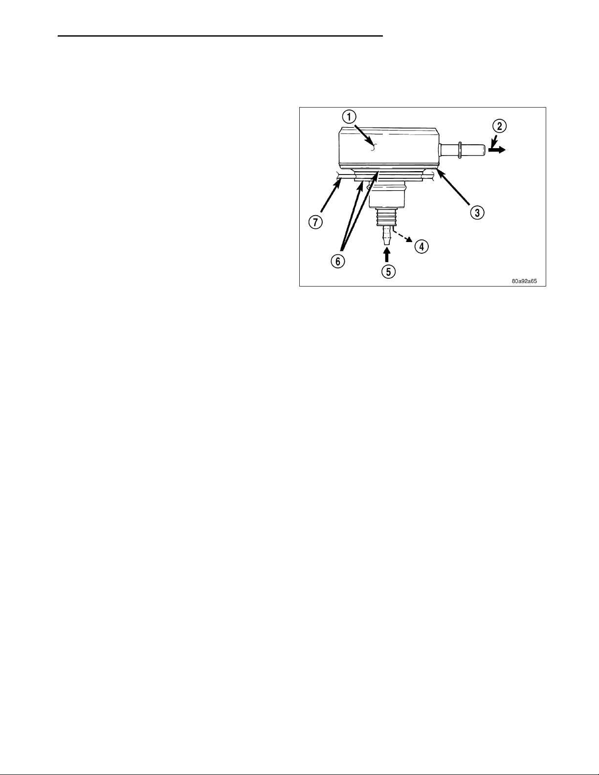
A combination fuel filter and fuel pressure regulator (3)
is used on all engines. It is located on the top of the
fuel pump module. A separate frame mounted fuel filter is not used with any engine.
Both fuel filters (at bottom of fuel pump module and
within fuel pressure regulator) are designed for
extended service. They do not require normal scheduled maintenance. Filters should only be replaced if a
diagnostic procedure indicates to do so.
OPERATION
Fuel Pressure Regulator Operation: The pressure regulator is a mechanical device that is not controlled by
engine vacuum or the Powertrain Control Module (PCM).
The regulator is calibrated to maintain fuel system operating pressure of approximately 58 ± 2 psi at the fuel injec-
tors. It contains a diaphragm, calibrated springs and a fuel return valve. The internal fuel filter is also part of the
assembly.
Fuel is supplied to the filter/regulator by the electric fuel pump through an opening tube at the bottom of filter/regulator.
The regulator acts as a check valve to maintain some fuel pressure when the engine is not operating. This will help
to start the engine. A second check valve is located at the outlet end of the electric fuel pump. Refer to Fuel Pump
- Description and Operation for more information.
If fuel pressure at the pressure regulator exceeds approximately 60 psi, an internal diaphragm opens and excess
fuel pressure is routed back into the tank through the bottom of pressure regulator.
Both fuel filters (at bottom of fuel pump module and within fuel pressure regulator) are designed for extended service. They do not require normal scheduled maintenance. Filters should only be replaced if a diagnostic procedure
indicates to do so.
Page 10
14 - 10 FUEL DELIVERY - GAS DR
SENSOR - FUEL LEVEL SENDING UNIT
DESCRIPTION
The fuel gauge sending unit (fuel level sensor) is attached to the side of the fuel pump module. The sending unit
consists of a float, an arm, and a variable resistor track (card).
OPERATION
The fuel pump module has 4 different circuits (wires). Two of these circuits are used for the fuel gauge sending unit
for fuel gauge operation, and for certain OBD II emission requirements. The other 2 wires are used for electric fuel
pump operation.
For Fuel Gauge Operation: A constant current source is supplied to the resistor track on the fuel gauge sending
unit. This is fed directly from the Powertrain Control Module (PCM). NOTE: For diagnostic purposes, this 12V
power source can only be verified with the circuit opened (fuel pump module electrical connector
unplugged). With the connectors plugged, output voltages will vary from about 0.6 volts at FULL, to about
8.6 volts at EMPTY (about 8.6 volts at EMPTY for Jeep models, and about 7.0 volts at EMPTY for Dodge
Truck models). The resistor track is used to vary the voltage (resistance) depending on fuel tank float level. As fuel
level increases, the float and arm move up, which decreases voltage. As fuel level decreases, the float and arm
move down, which increases voltage. The varied voltage signal is returned back to the PCM through the sensor
return circuit.
Both of the electrical circuits between the fuel gauge sending unit and the PCM are hard-wired (not multi-plexed).
After the voltage signal is sent from the resistor track, and back to the PCM, the PCM will interpret the resistance
(voltage) data and send a message across the multi-plex bus circuits to the instrument panel cluster. Here it is
translated into the appropriate fuel gauge level reading. Refer to Instrument Panel for additional information.
For OBD II Emission Monitor Requirements: The PCM will monitor the voltage output sent from the resistor track
on the sending unit to indicate fuel level. The purpose of this feature is to prevent the OBD II system from recording/
setting false misfire and fuel system monitor diagnostic trouble codes. The feature is activated if the fuel level in the
tank is less than approximately 15 percent of its rated capacity. If equipped with a Leak Detection Pump (EVAP
system monitor), this feature will also be activated if the fuel level in the tank is more than approximately 85 percent
of its rated capacity.
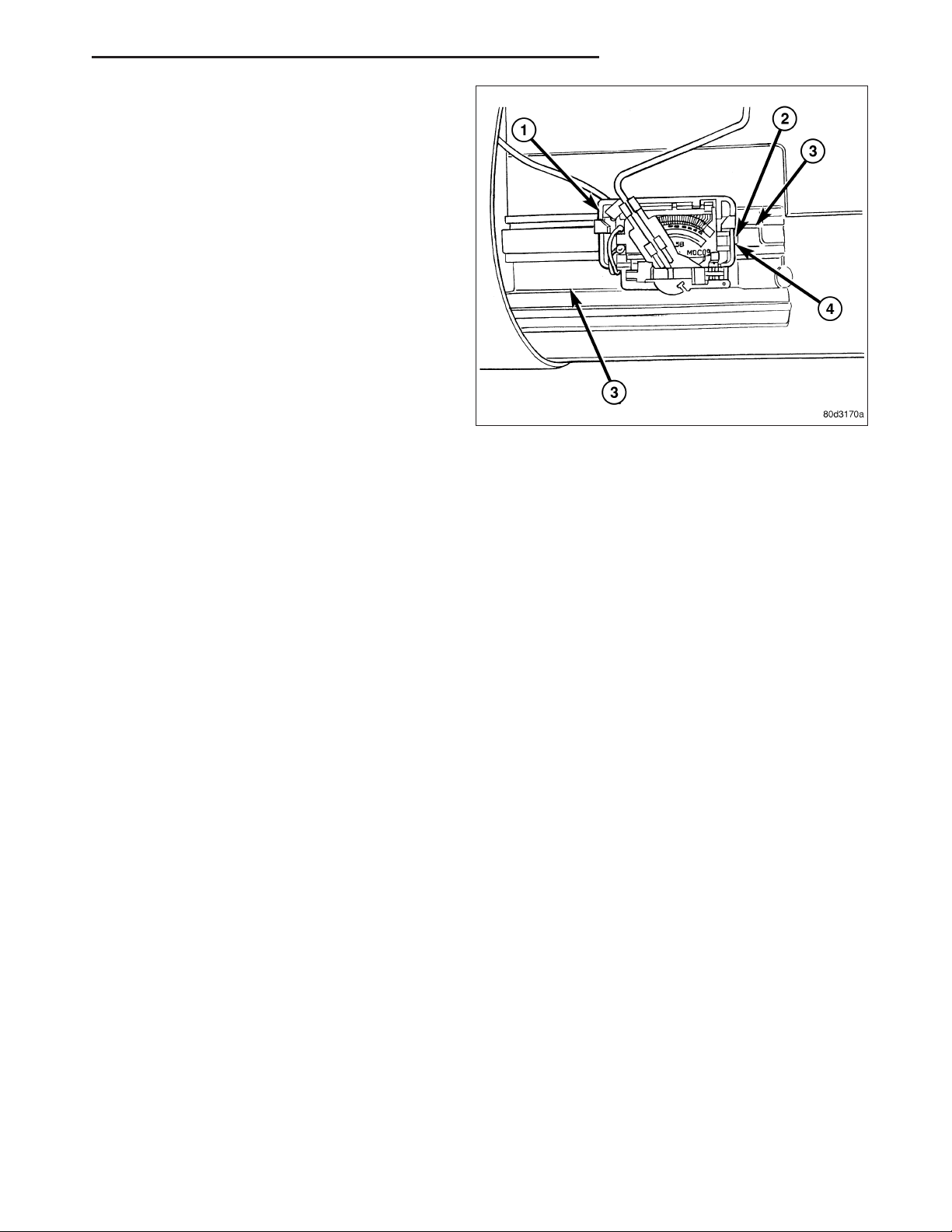
REMOVAL
The fuel level sending unit (fuel level sensor) and float
assembly (7) is located on the side of the fuel pump
module.
1. Remove fuel pump module from fuel tank. Refer to
Fuel Pump Module Removal/Installation.
2. Disconnect 4–wire electrical connector (3) from fuel
pump module. Separate necessary sending unit
wiring from connector using terminal pick / removal
tool. Refer to Special Tools in 8W Wiring for tool
part numbers.
Page 11
DR FUEL DELIVERY - GAS 14 - 11
3. To remove sending unit from pump module, lift on
plastic locking tab while sliding sending unit tracks.
INSTALLATION
1. Connect necessary wiring into electrical connectors. Connect 4–wire electrical connector to pump module.
2. Position sending unit to pump module. Slide and snap into place.
3. Install fuel pump module. Refer to Fuel Pump Module Removal/Installation.
Page 12

14 - 12 FUEL DELIVERY - GAS DR
LINES, FUEL
DESCRIPTION
Also refer to Quick-Connect Fittings.
WARNING: The fuel system may be under a constant pressure (even with the engine off). Before servicing
any fuel system hoses, fittings, lines, or most components, fuel system pressure must be released. Refer to
the fuel system pressure release procedure.
The lines/tubes/hoses used on fuel injected vehicles are of a special construction. This is due to the higher fuel
pressures and the possibility of contaminated fuel in this system. If it is necessary to replace these lines/tubes/
hoses, only those marked EFM/EFI may be used.
If equipped: The hose clamps used to secure rubber hoses on fuel injected vehicles are of a special rolled edge
construction. This construction is used to prevent the edge of the clamp from cutting into the hose. Only these rolled
edge type clamps may be used in this system. All other types of clamps may cut into the hoses and cause highpressure fuel leaks.
Use new original equipment type hose clamps.
Page 13

DR FUEL DELIVERY - GAS 14 - 13
FITTING-QUICK CONNECT
DESCRIPTION
Different types of quick-connect fittings are used to attach the various fuel system components, lines and tubes.
These are: a single-button type, a two-button type, a pinch type, a single-tab type, a two-tab type or a plastic
retainer ring type. Some are equipped with safety latch clips. Some may require the use of a special tool for disconnection and removal. (Refer to 14 - FUEL SYSTEM/FUEL DELIVERY/QUICK CONNECT FITTING - STANDARD
PROCEDURE)
CAUTION: Before separating a quick-connect fitting, pay attention to what type of fitting is being used by
referring to Quick-Connect Fitting Removal. This will prevent unnecessary fitting or fitting latch breakage.
CAUTION: The interior components (O-rings, clips) of quick-connect fittings are not serviced separately, but
new plastic spacers and latches are available for some types. If service parts are not available, do not
attempt to repair the damaged fitting or fuel line (tube). If repair is necessary, replace the complete fuel line
(tube) assembly.
STANDARD PROCEDURE - QUICK-CONNECT FITTINGS
Different types of quick-connect fittings are used to attach the various fuel system components, lines and tubes.
These are: a single-button type, a two-button type, a pinch type, a single-tab type, a two-tab type or a plastic
retainer ring type. Some are equipped with safety latch clips. Some may require the use of a special tool for disconnection and removal.
DISCONNECTING
WARNING: The fuel system is under a constant pressure (even with engine off). Before servicing any fuel
system hose, fitting or line, fuel system pressure must be released. Refer to fuel system pressure release
procedure.
CAUTION: Before separating a quick-connect fitting, pay attention to what type of fitting is being used by
referring to Quick-Connect Fitting Removal. This will prevent unnecessary fitting or fitting latch breakage.
CAUTION: The interior components (O-rings, clips) of quick-connect fittings are not serviced separately, but
new plastic spacers and latches are available for some types. If service parts are not available, do not
attempt to repair the damaged fitting or fuel line (tube). If repair is necessary, replace the complete fuel line
(tube) assembly.
1. Perform fuel pressure release procedure. Refer to Fuel Pressure Release Procedure.
2. Disconnect negative battery cable from battery.
3. Clean fitting of any foreign material before disassembly.
Page 14
14 - 14 FUEL DELIVERY - GAS DR
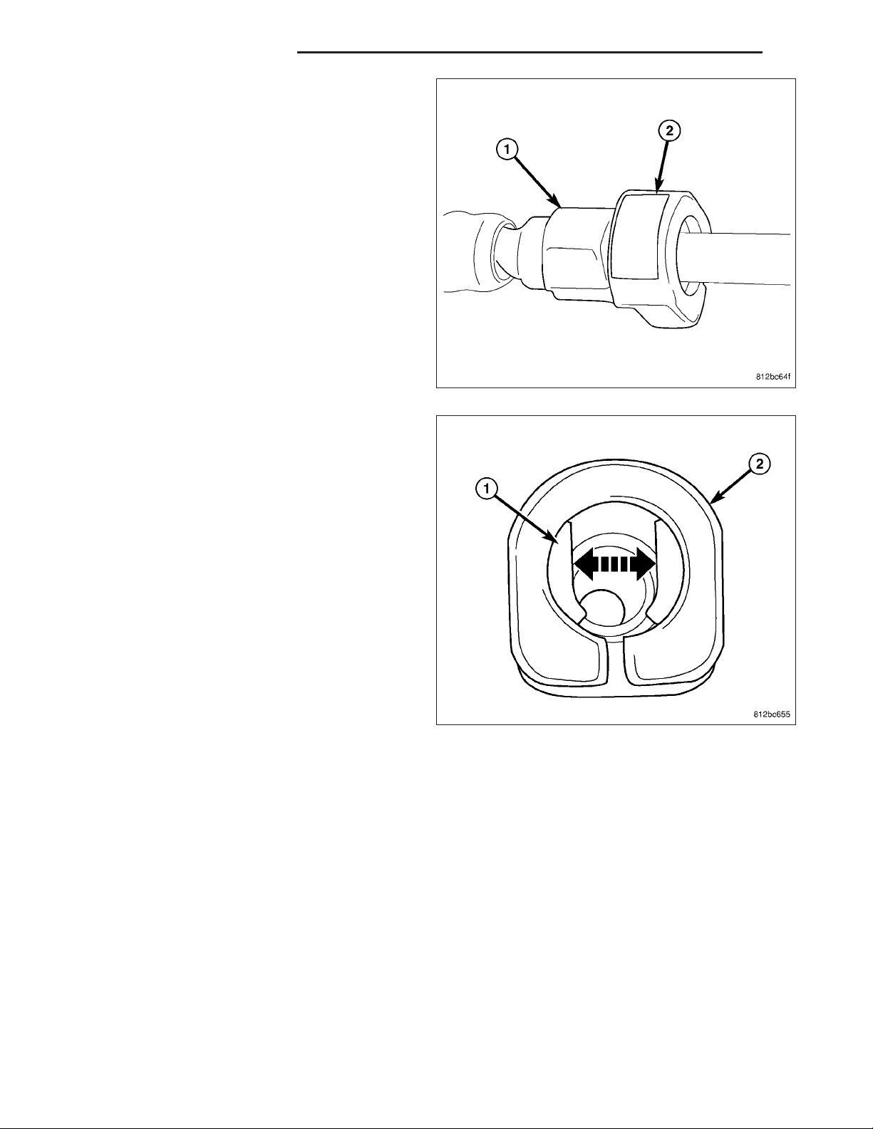
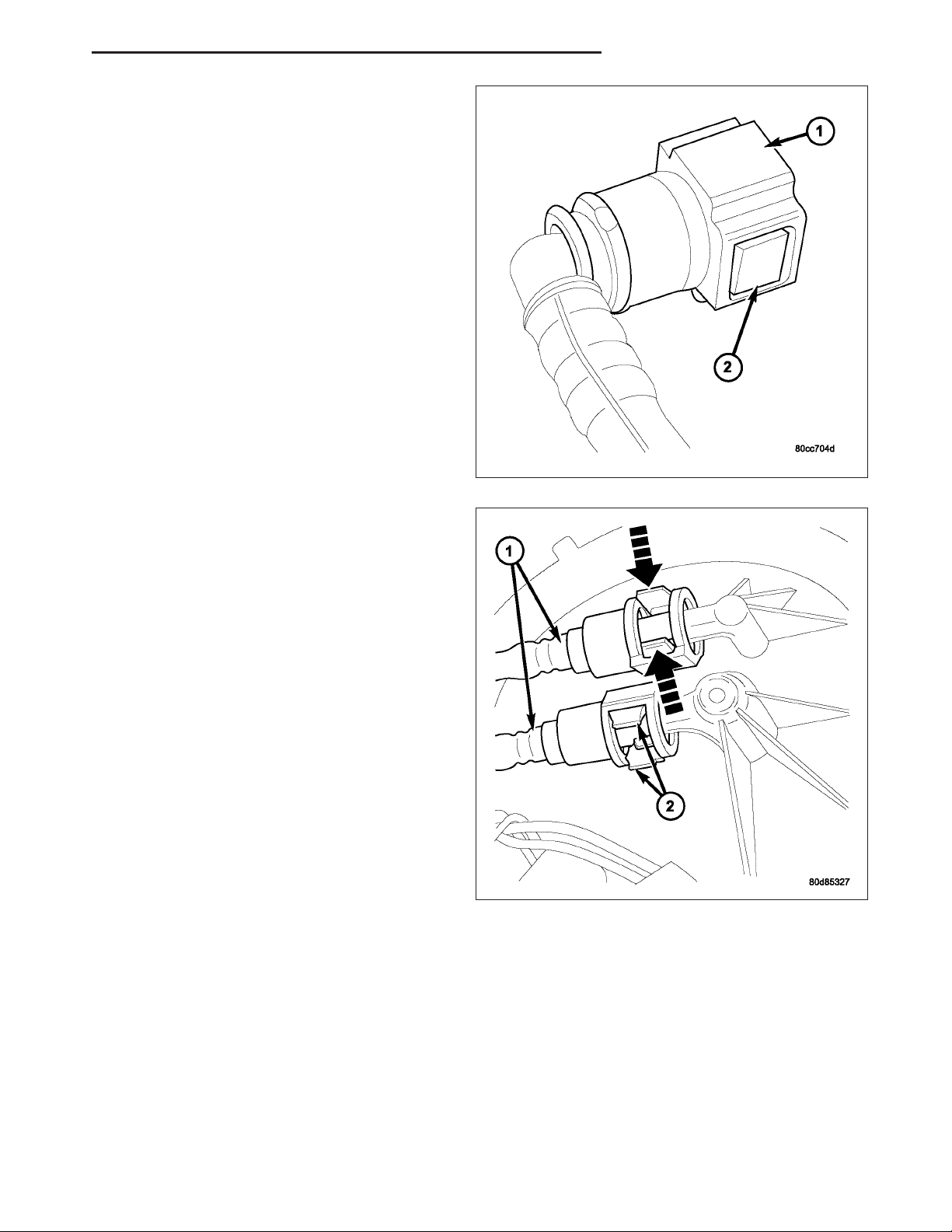
4. Single–Button Type Fitting: This type of fitting is
equipped with a single push-button (2) located on
the quick-connect fitting.
5. The push-button is attached to two internal latches
(1). To disconnect, press on push-button with your
thumb and unlatch fitting from fuel line. Special
tools are not required for disconnection. DO NOT
ATTEMPT TO PRY OR PULL UP ON PUSH-BUTTON. LATCHES WILL BE BROKEN.
Page 15
DR FUEL DELIVERY - GAS 14 - 15
6. Perform fuel pressure release procedure. Refer to
Fuel Pressure Release Procedure.
7. Disconnect negative battery cable from battery.
8. Clean fitting of any foreign material before disassembly.
9. 2–Button Type Fitting: This type of fitting (1) is
equipped with a push-button located on each side
of quick-connect fitting (2). Press on both buttons
simultaneously for removal. Special tools are not
required for disconnection.
10. Pinch-Type Fitting: This fitting (1) is equipped
with two finger tabs (2). Pinch both tabs together
while removing fitting. Special tools are not
required for disconnection.
Page 16
14 - 16 FUEL DELIVERY - GAS DR
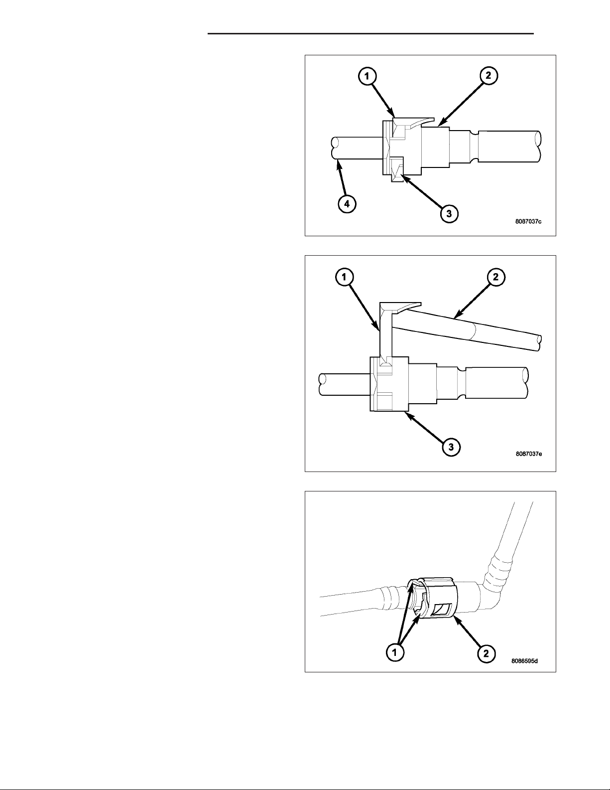
11. Single-Tab Type Fitting: This type of fitting (3) is
equipped with a single pull tab (1). The tab is
removable. After tab is removed, quick-connect fitting can be separated from fuel system component. Special tools are not required for
disconnection.
12. Press release tab on side of fitting to release pull
tab (1). If release tab is not pressed prior to
releasing pull tab, pull tab will be damaged.
13. While pressing release tab on side of fitting, use
screwdriver (2) to pry up pull tab.
14. Raise pull tab until it separates from quick-con-
nect fitting.
15. Two-Tab Type Fitting: This type of fitting (2) is
equipped with tabs located on both sides of fitting
(1). The tabs are supplied for disconnecting quickconnect fitting from component being serviced.
a. To disconnect quick-connect fitting, squeeze
plastic retainer tabs (1) against sides of quickconnect fitting with your fingers. Tool use is not
required for removal and may damage plastic
retainer.
b. Pull fitting from fuel system component being
serviced.
c. The plastic retainer will remain on component
being serviced after fitting is disconnected. The
O-rings and spacer will remain in quick-connect
fitting connector body.
Page 17
DR FUEL DELIVERY - GAS 14 - 17
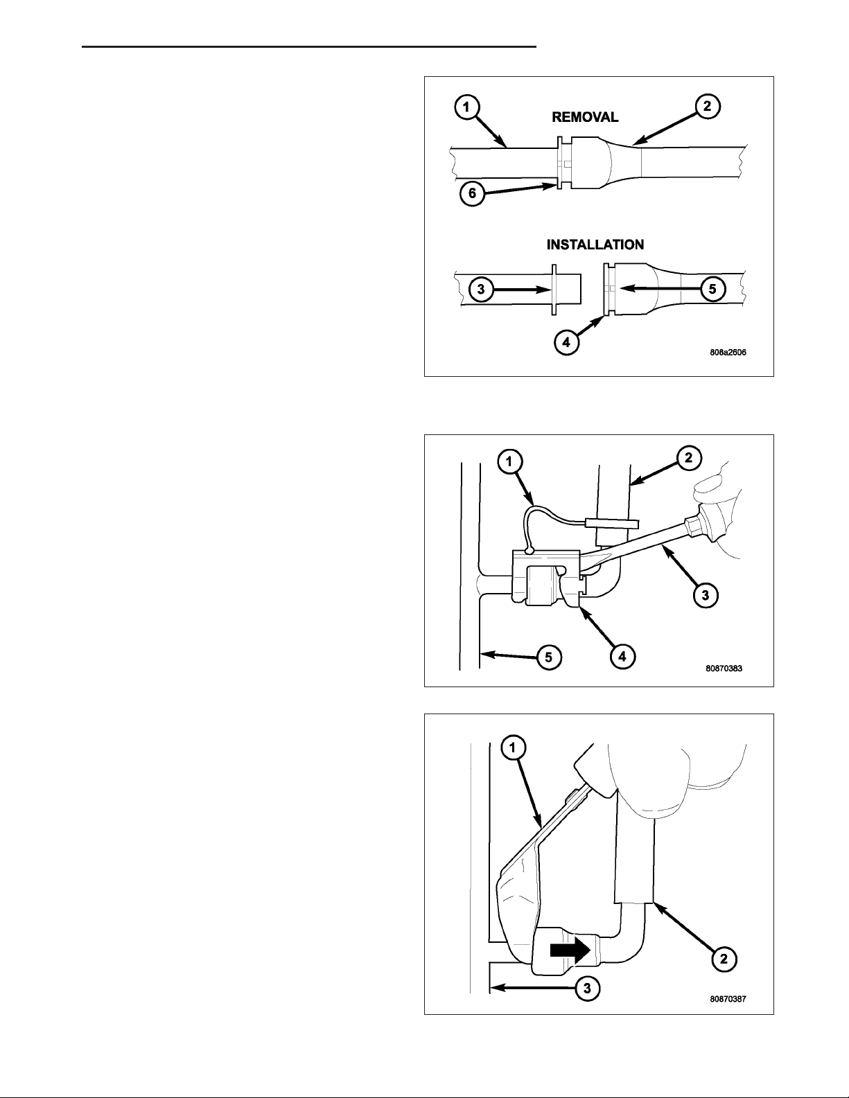
16. Plastic Retainer Ring Type Fitting: This type of
fitting can be identified by the use of a full-round
plastic retainer ring (4) usually black in color.
a. To release fuel system component from quick-
connect fitting, firmly push fitting towards component being serviced while firmly pushing
plastic retainer ring into fitting (6). With plastic
ring depressed, pull fitting from component.
The plastic retainer ring must be pressed
squarely into fitting body. If this retainer is
cocked during removal, it may be difficult
to disconnect fitting. Use an open-end
wrench on shoulder of plastic retainer ring
to aid in disconnection.
b. After disconnection, plastic retainer ring will
remain with quick-connect fitting connector
body.
c. Inspect fitting connector body, plastic retainer
ring and fuel system component for damage. Replace as necessary.
17. Latch Clips — Type 1: Depending on vehicle
model and engine, 2 different types of safety latch
clips are used. Type-1 (4) is tethered to fuel line
and type-2 is not. A special tool will be necessary
to disconnect fuel line after latch clip is removed.
The latch clip may be used on certain fuel line/
fuel rail connection, or to join fuel lines together.
18. Pry up on latch clip with a screwdriver (3).
19. Slide latch clip toward fuel rail while lifting with
screwdriver.
20. Insert special fuel line removal tool (Snap-On
number FIH 9055-1 or equivalent) into fuel line
(1). Use tool to release locking fingers in end of
line.
21. With special tool still inserted, pull fuel line from
fuel rail.
22. After disconnection, locking fingers will remain
within quick-connect fitting at end of fuel line.
23. Disconnect quick-connect fitting from fuel system
component being serviced.
Page 18
14 - 18 FUEL DELIVERY - GAS DR
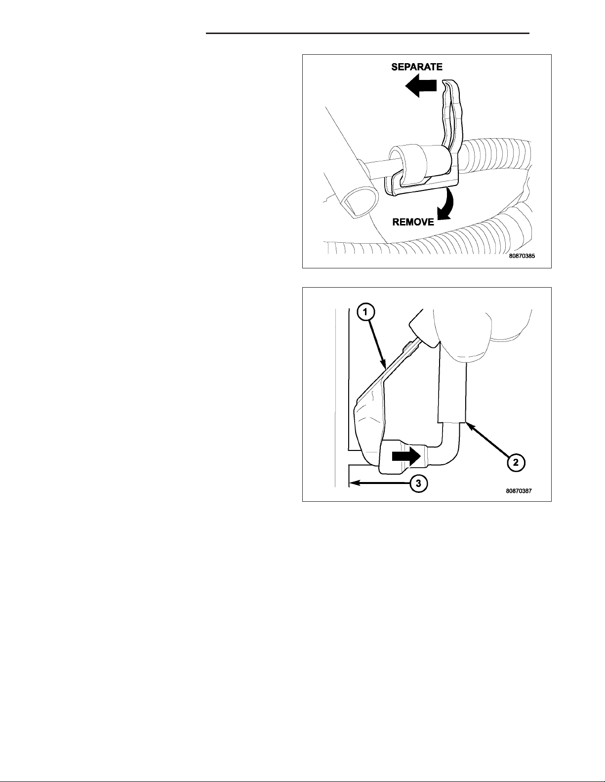
24. Latch Clips — Type 2: Depending on vehicle
model and engine, 2 different types of safety latch
clips are used. Type-1 is tethered to fuel line and
type-2 is not. A special tool will be necessary to
disconnect fuel line after latch clip is removed.
The latch clip may be used on certain fuel line/
fuel rail connection, or to join fuel lines together.
25. Type 2: Separate and unlatch small arms (1) on
end of clip and swing away from fuel line.
26. Slide latch clip toward fuel rail while lifting with
screwdriver.
27. Insert special fuel line removal tool (Snap-On
number FIH 9055-1 or equivalent) into fuel line
(1). Use tool to release locking fingers in end of
line.
28. With special tool still inserted, pull fuel line from
fuel rail.
29. After disconnection, locking fingers will remain
within quick-connect fitting at end of fuel line.
30. Disconnect quick-connect fitting from fuel system
component being serviced.
CONNECTING
1. Inspect quick-connect fitting body and fuel system component for damage. Replace as necessary.
2. Prior to connecting quick-connect fitting to component being serviced, check condition of fitting and component.
Clean parts with a lint-free cloth. Lubricate with clean engine oil.
3. Insert quick-connect fitting into fuel tube or fuel system component until built-on stop on fuel tube or component
rests against back of fitting.
4. Continue pushing until a click is felt.
5. Single-tab type fitting: Push new tab down until it locks into place in quick-connect fitting.
6. Verify a locked condition by firmly pulling on fuel tube and fitting (15-30 lbs.).
7. Latch Clip Equipped: Install latch clip (snaps into position). If latch clip will not fit, this indicates fuel line is
not properly installed to fuel rail (or other fuel line). Recheck fuel line connection.
8. Connect negative cable to battery.
9. Start engine and check for leaks.
Page 19

DR FUEL DELIVERY - GAS 14 - 19
MODULE-FUEL PUMP
DESCRIPTION
The electric fuel pump is located inside of the fuel pump module. A 12 volt, permanent magnet, electric motor powers the fuel pump. The electric fuel pump is not a separate, serviceable component.
OPERATION
Voltage to operate the electric pump is supplied through the fuel pump relay.
Fuel is drawn in through a filter at the bottom of the module and pushed through the electric motor gearset to the
pump outlet.
Check Valve Operation: The bottom section of the fuel pump module contains a one-way check valve to prevent
fuel flow back into the tank and to maintain fuel supply line pressure (engine warm) when pump is not operational.
It is also used to keep the fuel supply line full of gasoline when pump is not operational. After the vehicle has cooled
down, fuel pressure may drop to 0 psi (cold fluid contracts), but liquid gasoline will remain in fuel supply line
between the check valve and fuel injectors. Fuel pressure that has dropped to 0 psi on a cooled down vehicle
(engine off) is a normal condition.
The electric fuel pump is not a separate, serviceable component.
Page 20
14 - 20 FUEL DELIVERY - GAS DR
MODULE - FUEL PUMP
DESCRIPTION
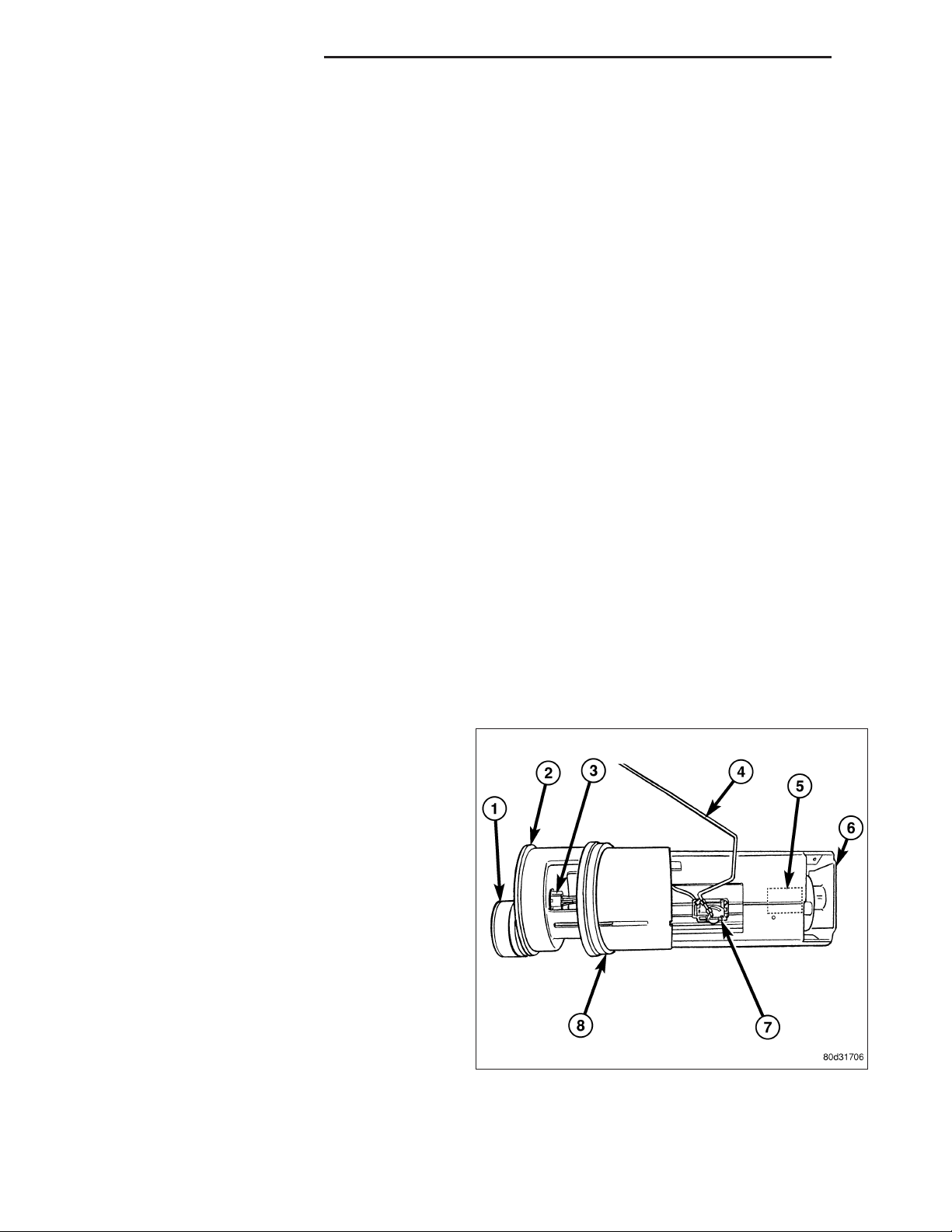
The fuel pump module assembly is located on the top of the fuel tank. The complete assembly contains the following components:
• A combination fuel filter/fuel pressure regulator
• A separate fuel pick-up, or inlet filter
• An electric fuel pump
• A lockring to retain pump module to tank
• A soft gasket between tank flange and module
• A fuel gauge sending unit (fuel level sensor)
• Fuel line connection
The fuel gauge sending unit may be serviced separately. If the electrical fuel pump, primary inlet filter, fuel filter or
fuel pressure regulator require service, the fuel pump module must be replaced.
OPERATION
Refer to Fuel Pump, Inlet Filter, Fuel Filter / Fuel Pressure Regulator and Fuel Gauge Sending Unit.
REMOVAL
WARNING: The fuel system may be under a constant pressure (even with the engine off). Before servicing
the fuel pump module, the fuel system pressure must be released.
1. Drain and remove fuel tank. Refer to Fuel Tank
Removal/Installation.
2. Note rotational position of module before attempting removal. An indexing arrow is located on top of
module for this purpose.
3. Position Special Tool 9340 (3) into notches on outside edge of lockring (5).
4. Install 1/2 inch drive breaker bar (1) to tool 9340
(3).
5. Rotate breaker bar counter-clockwise to remove
lockring (5).
6. Remove lockring. The module will spring up slightly
when lockring is removed.
7. Remove module from fuel tank. Be careful not to
bend float arm while removing.
Page 21
DR FUEL DELIVERY - GAS 14 - 21
INSTALLATION
1. Using a new seal (gasket), position fuel pump module into opening in fuel tank.
2. Position lockring (5) over top of fuel pump module.
3. Rotate module until embossed alignment arrow
points to center alignment mark. This step must be
performed to prevent float from contacting side of
fuel tank. Also be sure fuel fitting on top of pump
module is pointed to drivers side of vehicle.
4. Install Special Tool 9340 (3) to lockring.
5. Install 1/2 inch drive breaker (1) into Special Tool
9340 (3).
6. Tighten lockring (clockwise) until all seven notches
have engaged.
7. Install fuel tank. Refer to Fuel Tank
Removal/Installation.
Page 22
14 - 22 FUEL DELIVERY - GAS DR
RAIL - FUEL
DESCRIPTION
The fuel injector rail is used to mount the fuel injectors to the engine.
OPERATION
High pressure from the fuel pump is routed to the fuel rail. The fuel rail then supplies the necessary fuel to each
individual fuel injector.
A quick-connect fitting with a safety latch clip is used to attach the fuel line to the fuel rail.
The fuel rail is not repairable.
CAUTION: The left and right sections of the fuel rail are connected with either a flexible connecting hose, or
joints. Do not attempt to separate the rail halves at these connecting hose or joints. Due to the design of
the connecting hose or joint, it does not use any clamps. Never attempt to install a clamping device of any
kind to the hose or joint. When removing the fuel rail assembly for any reason, be careful not to bend or
kink the connecting hose or joint.
REMOVAL
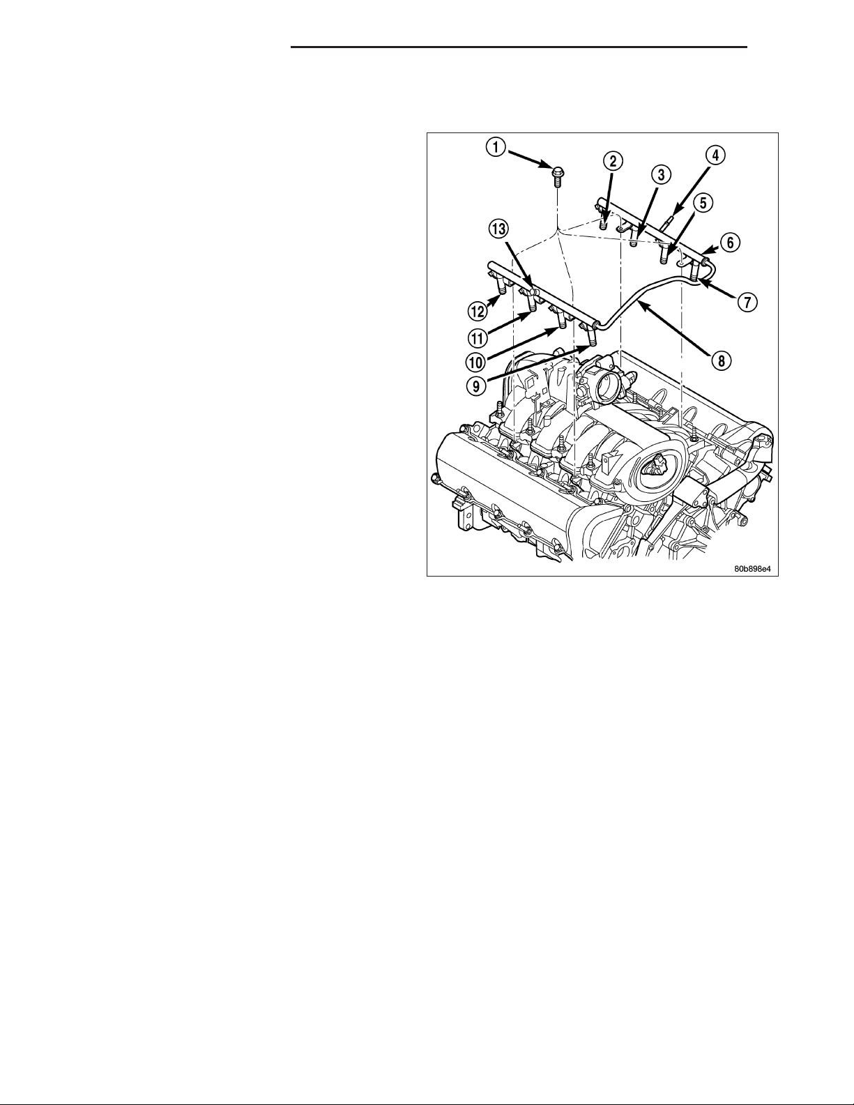
3.7L V-6
WARNING: The fuel system is under constant pressure even with engine off. Before servicing fuel rail, fuel
system pressure must be released.
CAUTION: The left and right fuel rails are replaced as an assembly. Do not attempt to separate rail halves
at connector tubes. Due to design of tubes, it does not use any clamps. Never attempt to install a clamping
device of any kind to tubes. When removing fuel rail assembly for any reason, be careful not to bend or
kink tubes.
1. Remove fuel tank filler tube cap.
2. Perform Fuel System Pressure Release Procedure.
(Refer to 14 - FUEL SYSTEM/FUEL DELIVERY STANDARD PROCEDURE)
3. Remove negative battery cable at battery.
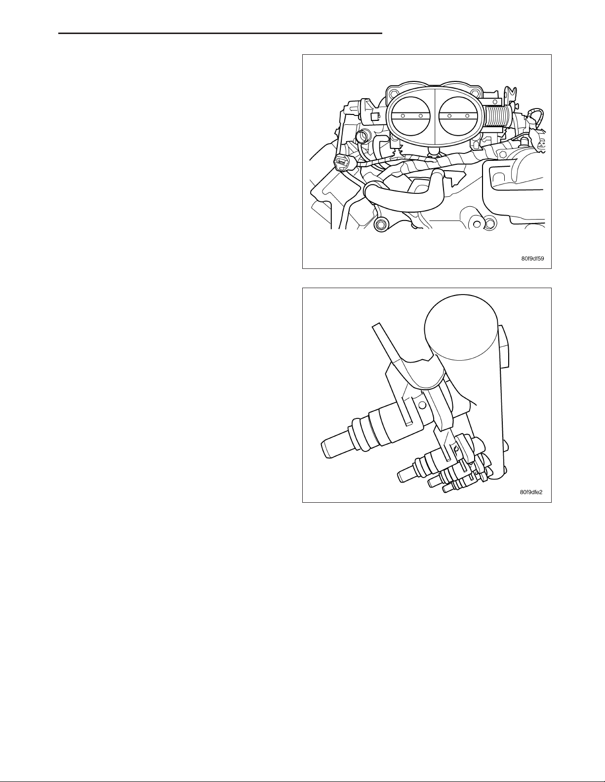
4. Remove air duct at throttle body air box.
5. Remove air box at throttle body.
6. Remove air resonator mounting bracket at front of
throttle body (2 bolts).
7. Disconnect fuel line latch clip and fuel line at fuel
rail. A special tool will be necessary for fuel line
disconnection. (Refer to 14 - FUEL SYSTEM/FUEL
DELIVERY/QUICK CONNECT FITTING - STANDARD PROCEDURE)
8. Remove necessary vacuum lines at throttle body.
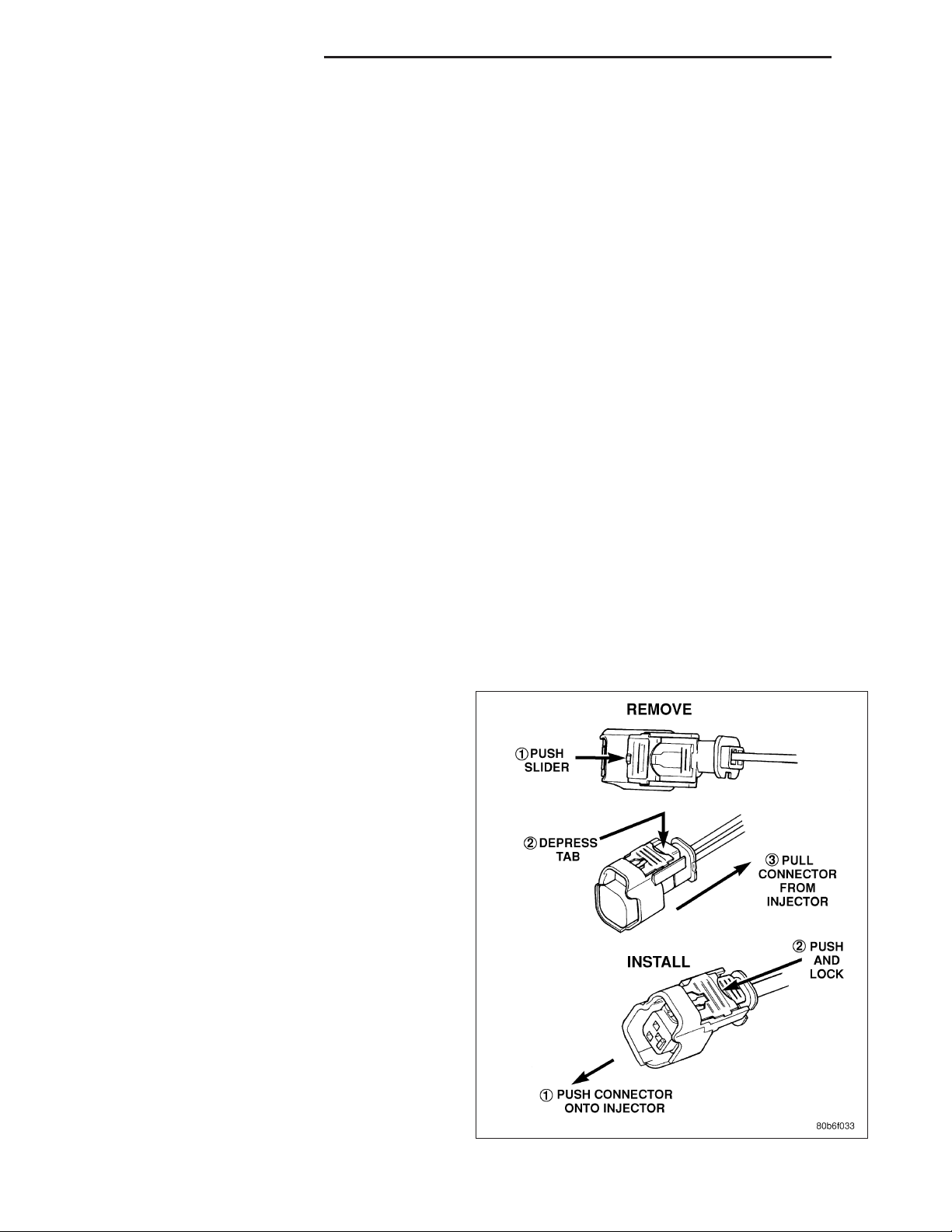
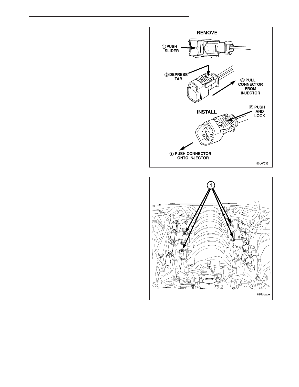
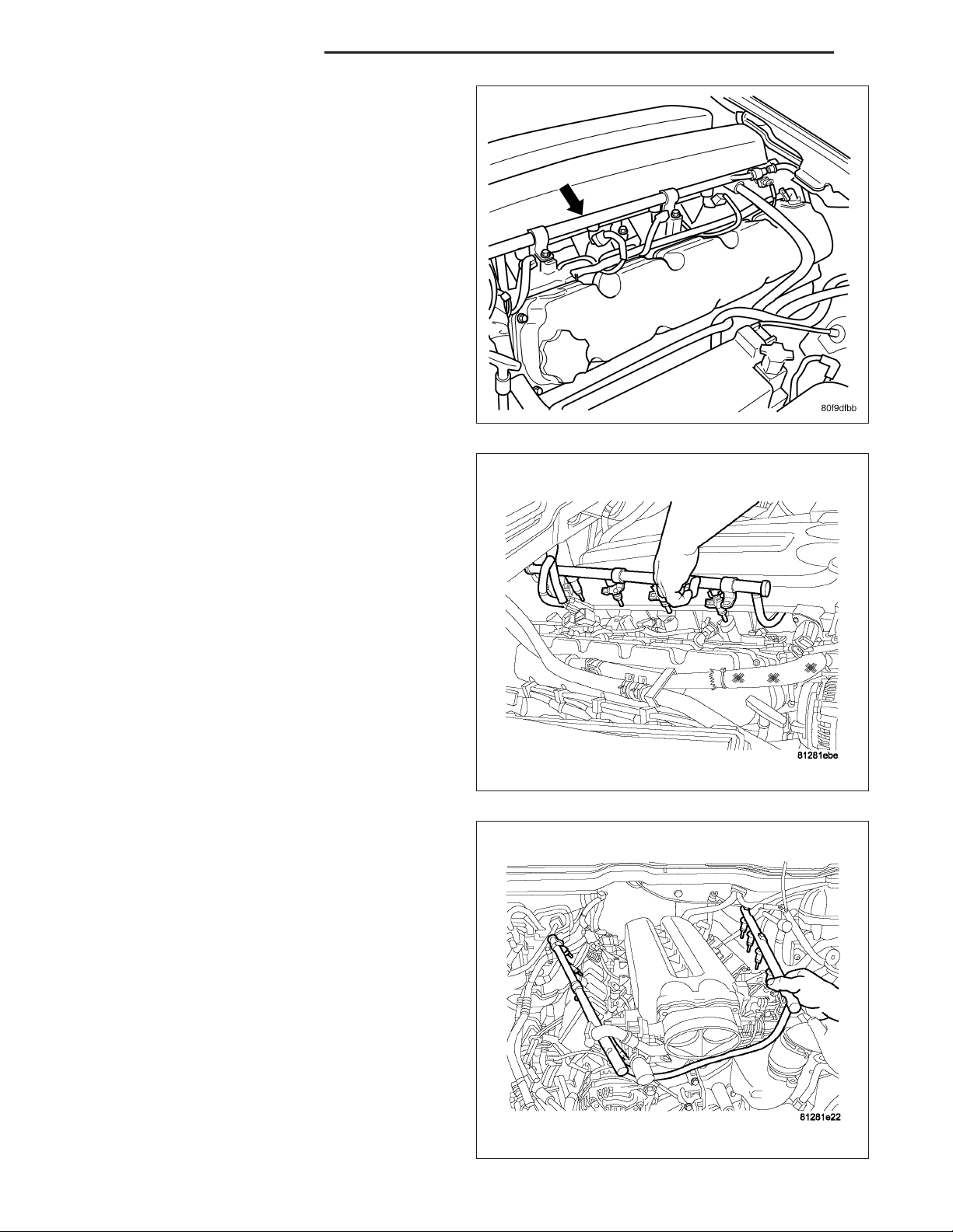
9. Disconnect electrical connectors at all 6 fuel injectors. To remove connector refer to. Push red colored slider away from injector (1). While pushing
slider, depress tab (2) and remove connector (3)
from injector. The factory fuel injection wiring harness is numerically tagged (INJ 1, INJ 2, etc.) for
injector position identification. If harness is not
tagged, note wiring location before removal.
10. Disconnect electrical connectors at all throttle body sensors.
Page 23
DR FUEL DELIVERY - GAS 14 - 23
11. Remove 6 ignition coils. (Refer to 8 - ELECTRICAL/IGNITION CONTROL/IGNITION COIL - REMOVAL)
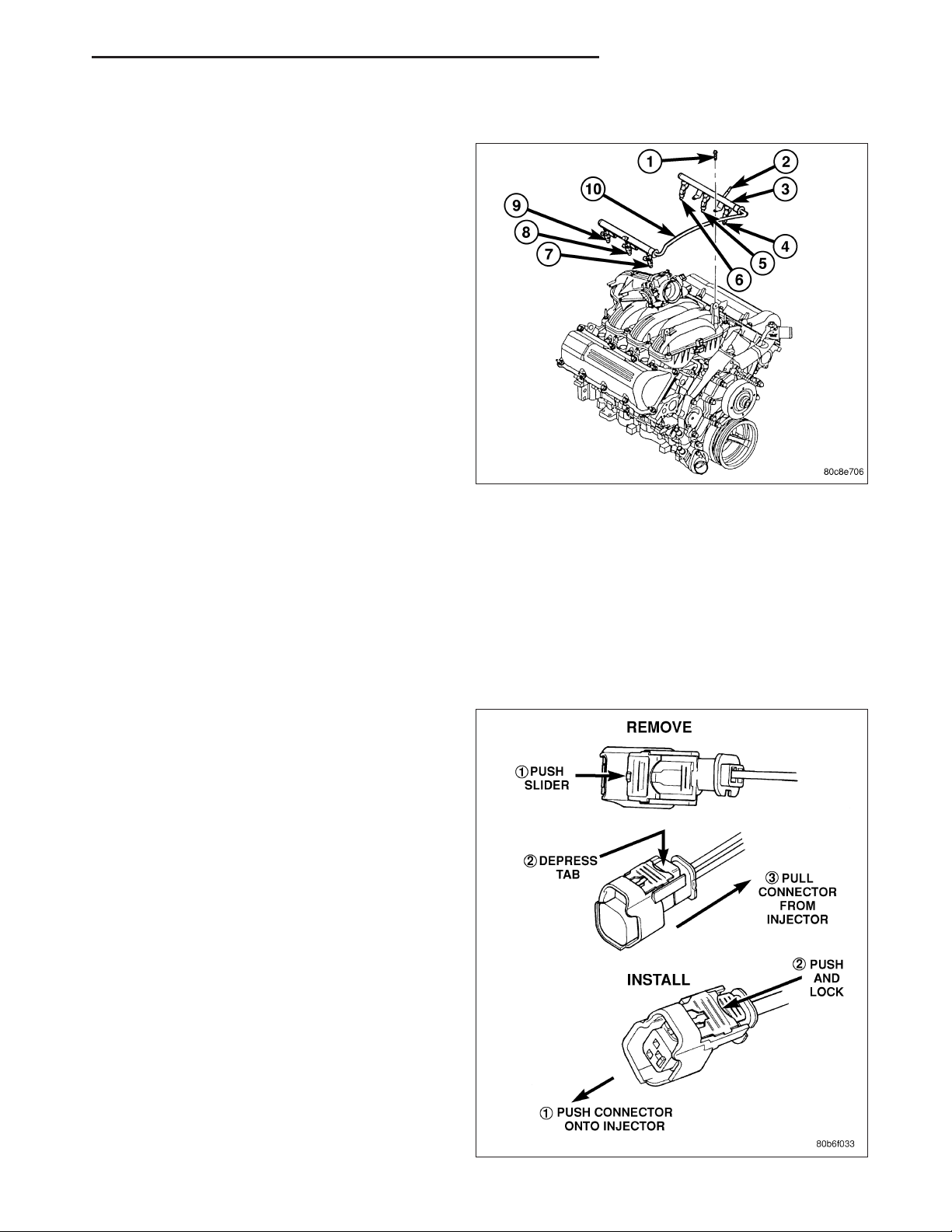
12. Remove 4 fuel rail mounting bolts (1).
13. Gently rock and pull left side of fuel rail until fuel
injectors just start to clear machined holes in cylinder head. Gently rock and pull right side of rail
until injectors just start to clear cylinder head
holes. Repeat this procedure (left/right) until all
injectors have cleared cylinder head holes.
14. Remove fuel rail (with injectors attached) from
engine.
15. If fuel injectors are to be removed, (Refer to 14 -
FUEL SYSTEM/FUEL INJECTION/FUEL INJECTOR - REMOVAL).
4.7L V-8
WARNING: The fuel system is under constant pressure even with engine off. Before servicing fuel rail, fuel
system pressure must be released.
CAUTION: The left and right fuel rails are replaced as an assembly. Do not attempt to separate rail halves
at connector tubes. Due to design of tubes, it does not use any clamps. Never attempt to install a clamping
device of any kind to tubes. When removing fuel rail assembly for any reason, be careful not to bend or
kink tubes.
1. Remove fuel tank filler tube cap.
2. Perform Fuel System Pressure Release Procedure.
(Refer to 14 - FUEL SYSTEM/FUEL DELIVERY STANDARD PROCEDURE)
3. Remove negative battery cable at battery.
4. Remove air duct at throttle body air box.
5. Remove air box at throttle body.
6. Remove air resonator mounting bracket at front of
throttle body (2 bolts).
7. Disconnect fuel line latch clip and fuel line at fuel
rail. A special tool will be necessary for fuel line
disconnection. (Refer to 14 - FUEL SYSTEM/FUEL
DELIVERY/QUICK CONNECT FITTING - STANDARD PROCEDURE)
8. Remove necessary vacuum lines at throttle body.
9. Disconnect electrical connectors at all 8 fuel injectors. To remove connector refer to. Push red colored slider away from injector (1). While pushing
slider, depress tab (2) and remove connector (3)
from injector. The factory fuel injection wiring harness is numerically tagged (INJ 1, INJ 2, etc.) for
injector position identification. If harness is not
tagged, note wiring location before removal.
Page 24
14 - 24 FUEL DELIVERY - GAS DR
10. Disconnect electrical connectors at all throttle body sensors.
11. Remove 8 ignition coils. (Refer to 8 - ELECTRICAL/IGNITION CONTROL/IGNITION COIL - REMOVAL)
12. Remove 4 fuel rail mounting bolts (1).
13. Gently rock and pull left side of fuel rail until fuel
injectors just start to clear machined holes in cylinder head. Gently rock and pull right side of rail
until injectors just start to clear cylinder head
holes. Repeat this procedure (left/right) until all
injectors have cleared cylinder head holes.
14. Remove fuel rail (with injectors attached) from
engine.
15. If fuel injectors are to be removed, (Refer to 14 -
FUEL SYSTEM/FUEL INJECTION/FUEL INJECTOR - REMOVAL).
5.7L
WARNING: The fuel system is under constant pressure even with engine off. Before servicing fuel rail, fuel
system pressure must be released. (Refer to 14 - FUEL SYSTEM/FUEL DELIVERY - STANDARD PROCEDURE)
CAUTION: The left and right fuel rails are replaced as an assembly. Do not attempt to separate rail halves
at connector tube. Due to design of tube, it does not use any clamps. Never attempt to install a clamping
device of any kind to tube. When removing fuel rail assembly for any reason, be careful not to bend or kink
tube.
Page 25
DR FUEL DELIVERY - GAS 14 - 25
1. Remove fuel tank filler tube cap.
2. Perform fuel system pressure release procedure.
(Refer to 14 - FUEL SYSTEM/FUEL DELIVERY STANDARD PROCEDURE)
3. Remove negative battery cable at battery.
4. Remove flex tube (air cleaner housing to engine).
5. Remove air resonator box at throttle body.
6. Disconnect electrical connectors at all 8 fuel injectors. Push red colored slider away from injector (1).
While pushing slider, depress tab (2) and remove
connector (3) from injector. The factory fuel injection wiring harness is numerically tagged (INJ 1,
INJ 2, etc.) for injector position identification. If harness is not tagged, note wiring location before
removal.
7. Disconnect electrical connectors at all throttle body
sensors.
8. Disconnect fuel supply tube quick connect fitting at
the fuel rail, (Refer to 14 - FUEL SYSTEM/FUEL
DELIVERY/QUICK CONNECT FITTING - STANDARD PROCEDURE).
9. Remove four fuel rail mounting bolts (1) and holddown clamps.
10. Gently rock and pull left side of fuel rail until fuel
injectors just start to clear machined holes in
intake manifold. Gently rock and pull right side of
rail until injectors just start to clear intake manifold
head holes. Repeat this procedure (left/right) until
all injectors have cleared machined holes.
11. Remove fuel rail (with injectors attached) from
engine.
12. If fuel injectors are to be removed, (Refer to 14 -
FUEL SYSTEM/FUEL INJECTION/FUEL INJECTOR - REMOVAL).
Page 26
14 - 26 FUEL DELIVERY - GAS DR
8.3L - SRT-10
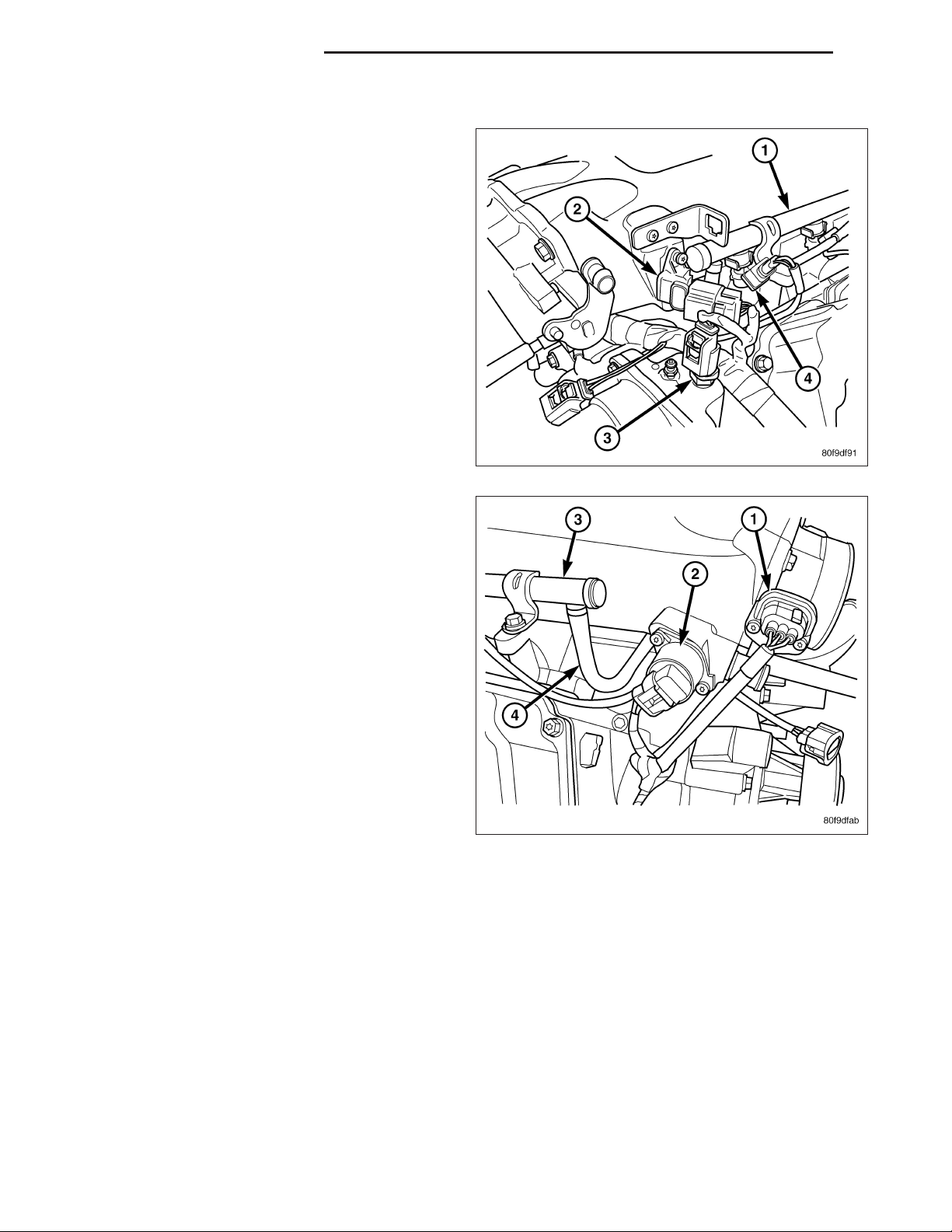
1. Disconnect the electrical connector to the MAP
sensor (2) and Coolant Temperature sensor (3).
2. Release fuel system pressure. Refer to Fuel Pressure Release Procedure in this section.
3. Disconnect negative battery cable.
4. Remove the air cleaner assembly, refer to the
Engine/Air Intake System/Air Cleaner Housing for
more information.
5. Disconnect the electrical connector to the TPS (1)
and Idle Air Control.
Page 27
DR FUEL DELIVERY - GAS 14 - 27
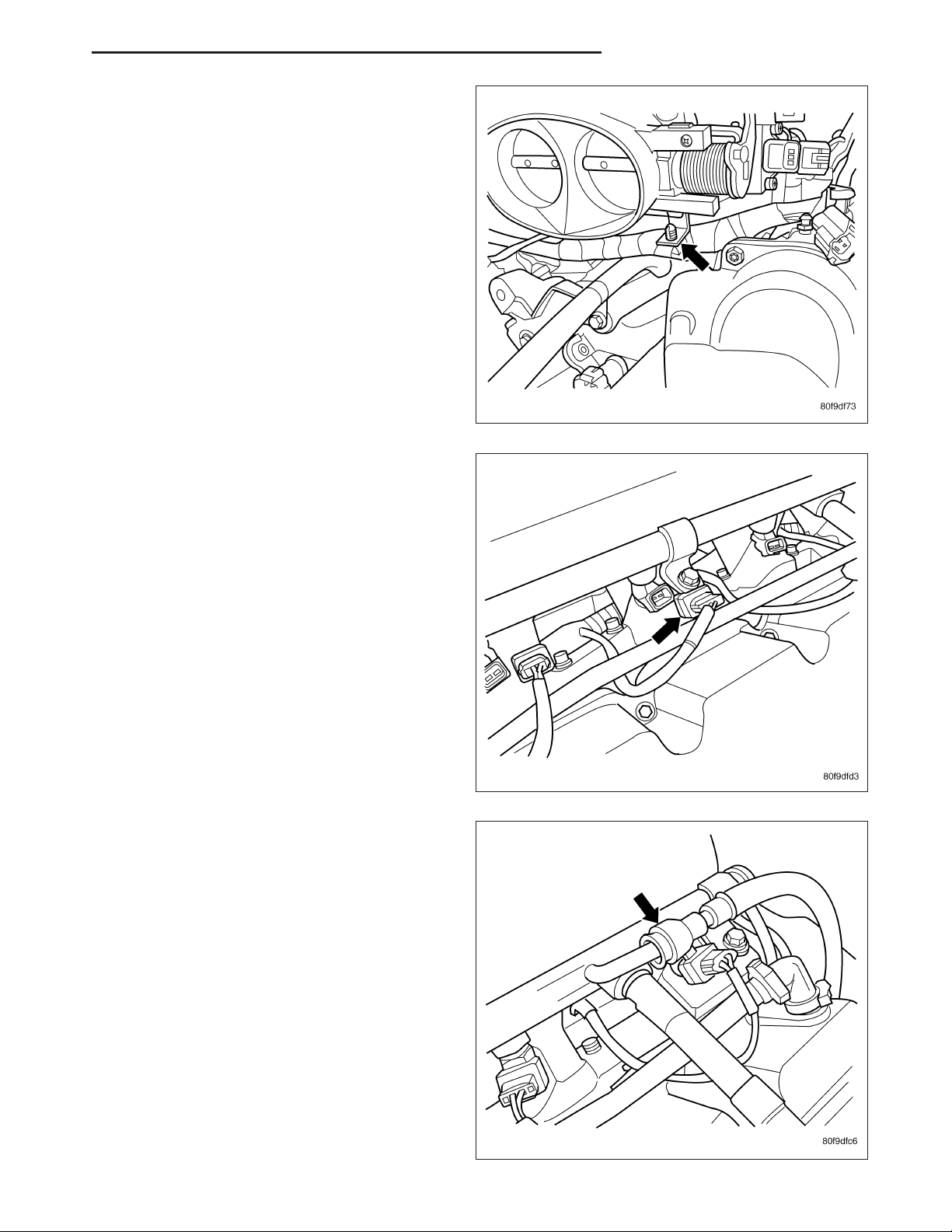
6. Remove the wiring harness from the wiring clips
under the throttle body.
7. Disconnect the electrical connector from the fuel
injectors.
8. Disconnect the fuel line quick connector.
Page 28
14 - 28 FUEL DELIVERY - GAS DR
9. Remove the bolts for the fuel rail.
10. Pull fuel rail and injectors straight up and out of
the intake manifold.
Page 29
DR FUEL DELIVERY - GAS 14 - 29
11. Move the fuel rail forward and out from under the
intake manifold and throttle body.
12. Remove the fuel injector from the fuel rail.
Page 30
14 - 30 FUEL DELIVERY - GAS DR
INSTALLATION
3.7L
1. If fuel injectors are to be installed, (Refer to 14 FUEL SYSTEM/FUEL INJECTION/FUEL INJECTOR - INSTALLATION).
2. Clean out fuel injector machined bores in intake
manifold.
3. Apply a small amount of engine oil to each fuel
injector O-ring. This will help in fuel rail installation.
4. Position fuel rail/fuel injector assembly to machined
injector openings in cylinder head.
5. Guide each injector into cylinder head. Be careful
not to tear injector O-rings.
6. Push right side of fuel rail down until fuel injectors
have bottomed on cylinder head shoulder. Push
left fuel rail down until injectors have bottomed on
cylinder head shoulder.
7. Install 4 fuel rail mounting bolts and tighten. (Refer
to 14 - FUEL SYSTEM/FUEL DELIVERY - SPECIFICATIONS)
8. Install 6 ignition coils. (Refer to 8 - ELECTRICAL/
IGNITION CONTROL/IGNITION COIL - INSTALLATION)
9. Connect electrical connectors to throttle body.
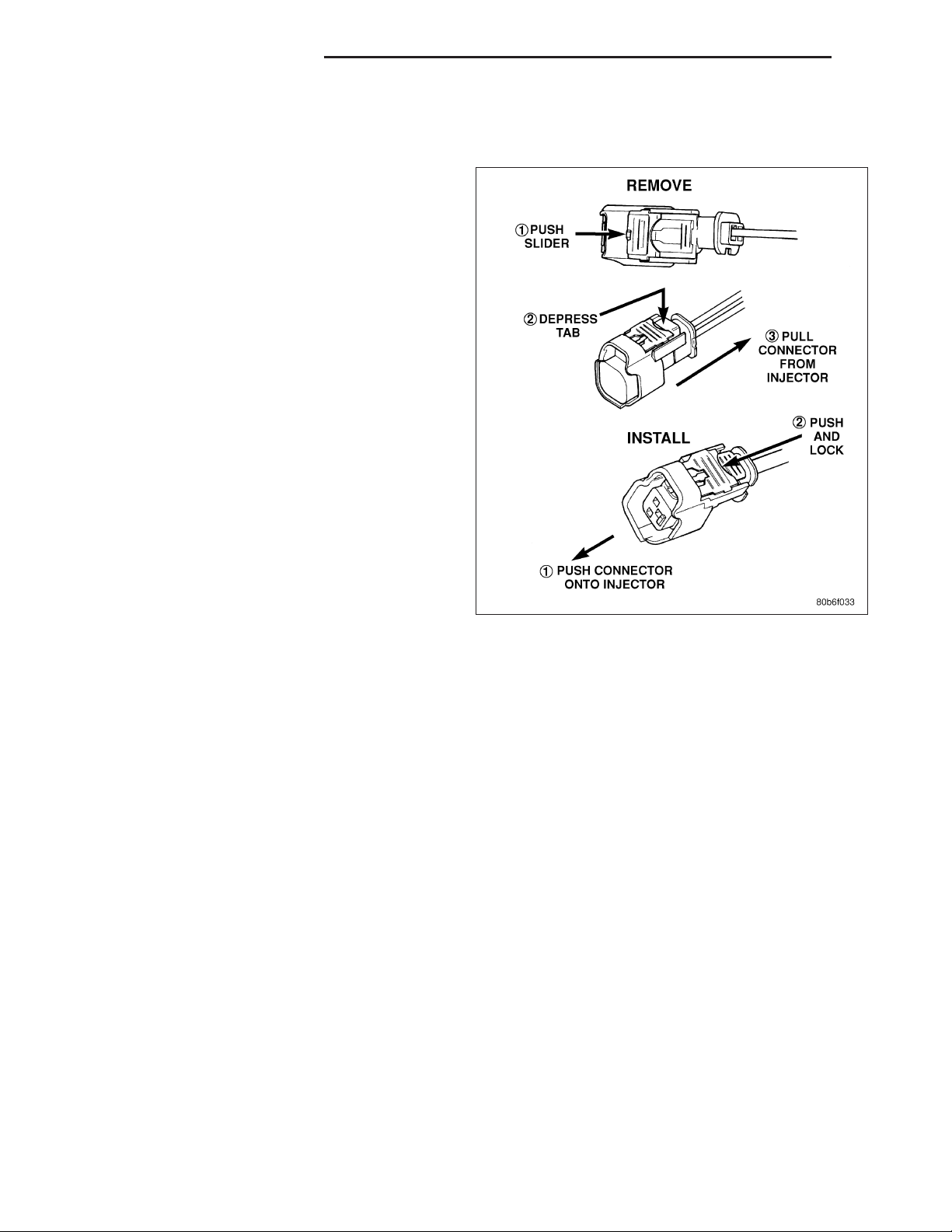
10. Connect electrical connectors at all fuel injectors.
To install connector, refer to. Push connector onto
injector (1) and then push and lock red colored slider (2). Verify connector is locked to injector by lightly tugging
on connector.
11. Connect necessary vacuum lines to throttle body.
12. Install air resonator mounting bracket near front of throttle body (2 bolts).
13. Connect fuel line latch clip and fuel line to fuel rail. (Refer to 14 - FUEL SYSTEM/FUEL DELIVERY/QUICK
CONNECT FITTING - STANDARD PROCEDURE)
14. Install air box to throttle body.
15. Install air duct to air box.
16. Connect battery cable to battery.
17. Start engine and check for leaks.
Page 31

DR FUEL DELIVERY - GAS 14 - 31
4.7L
1. If fuel injectors are to be installed, (Refer to 14 FUEL SYSTEM/FUEL INJECTION/FUEL INJECTOR - INSTALLATION).
2. Clean out fuel injector machined bores in intake
manifold.
3. Apply a small amount of engine oil to each fuel
injector O-ring. This will help in fuel rail installation.
4. Position fuel rail/fuel injector assembly to machined
injector openings in cylinder head.
5. Guide each injector into cylinder head. Be careful
not to tear injector O-rings.
6. Push right side of fuel rail down until fuel injectors
have bottomed on cylinder head shoulder. Push
left fuel rail down until injectors have bottomed on
cylinder head shoulder.
7. Install 4 fuel rail mounting bolts and tighten. (Refer
to 14 - FUEL SYSTEM/FUEL DELIVERY - SPECIFICATIONS)
8. Install 8 ignition coils. (Refer to 8 - ELECTRICAL/
IGNITION CONTROL/IGNITION COIL - INSTALLATION)
9. Connect electrical connectors to throttle body.
10. Connect electrical connectors at all fuel injectors.
To install connector, refer to. Push connector onto
injector (1) and then push and lock red colored slider (2). Verify connector is locked to injector by lightly tugging
on connector.
11. Connect necessary vacuum lines to throttle body.
12. Install air resonator mounting bracket near front of throttle body (2 bolts).
13. Connect fuel line latch clip and fuel line to fuel rail. (Refer to 14 - FUEL SYSTEM/FUEL DELIVERY/QUICK
CONNECT FITTING - STANDARD PROCEDURE)
14. Install air box to throttle body.
15. Install air duct to air box.
16. Connect battery cable to battery.
17. Start engine and check for leaks.
Page 32

14 - 32 FUEL DELIVERY - GAS DR
5.7L
1. If fuel injectors are to be installed, (Refer to 14 FUEL SYSTEM/FUEL INJECTION/FUEL INJECTOR - INSTALLATION).
2. Clean out fuel injector machined bores in intake
manifold.
3. Apply a small amount of engine oil to each fuel
injector O-ring. This will help in fuel rail installation.
4. Position fuel rail/fuel injector assembly to machined
injector openings in intake manifold.
5. Guide each injector into intake manifold. Be careful
not to tear injector O-rings.
6. Push right side of fuel rail down until fuel injectors
have bottomed on shoulders. Push left fuel rail
down until injectors have bottomed on shoulders.
7. Install 4 fuel rail holddown clamps and 4 mounting
bolts (1) (Refer to 14 - FUEL SYSTEM/FUEL
DELIVERY - SPECIFICATIONS).
8. Connect electrical connector to throttle body.
9. Connect electrical connectors at all fuel injectors.
Push connector onto injector (1) and then push and
lock red colored slider (2). Verify connector is
locked to injector by lightly tugging on connector.
10. Connect fuel line latch clip and fuel line to fuel
rail. (Refer to 14 - FUEL SYSTEM/FUEL DELIVERY/QUICK CONNECT FITTING - STANDARD
PROCEDURE).
11. Install air resonator to throttle body (2 bolts).
12. Install flexible air duct to air box.
13. Connect battery cable to battery.
14. Start engine and check for leaks.
8.3L - SRT-10
1. Install the fuel injectors to the fuel rail.
2. Install fuel rail under throttle body.
3. Apply a light coating of clean engine oil to the O-ring on the nozzle end of each injector.
4. Insert fuel injector nozzles into openings in intake manifold. Seat the injectors in place. Tighten fuel rail bolts to
12 N·m (105 in. lbs.).
5. Attach electrical connectors to fuel injectors.
Page 33

DR FUEL DELIVERY - GAS 14 - 33
6. Connect the electrical connector to the MAP sensor and Coolant Temperature sensor.
7. Connect the electrical connector to the TPS and Idle Air Control.
8. Install the wiring harness to the wiring clips under the throttle body.
9. Connect fuel supply tube to fuel rail. Refer to Quick Connect Fittings in the Fuel Delivery section.
10. Install the negative battery cable.
11. Install the air cleaner assembly, refer to the Engine/Air Intake System/Air Cleaner Housing for more information.
12. Use the DRBIIIT scan tool ASD Fuel System Test to pressurize the fuel system. Check for leaks.
Page 34

14 - 34 FUEL DELIVERY - GAS DR
TANK - FUEL
DESCRIPTION
The fuel tank is constructed of a plastic material. Its main functions are for fuel storage and for placement of the fuel
pump module, and (if equipped) certain ORVR components.
OPERATION
All models pass a full 360 degree rollover test without fuel leakage. To accomplish this, fuel and vapor flow controls
are required for all fuel tank connections.
Two check (control) valves are mounted into the top of the fuel tank. Refer to Fuel Tank Check Valve for additional
information.
An evaporation control system is connected to the fuel tank to reduce emissions of fuel vapors into the atmosphere.
When fuel evaporates from the fuel tank, vapors pass through vent hoses or tubes to a charcoal canister where
they are temporarily held. When the engine is running, the vapors are drawn into the intake manifold. Certain models are also equipped with a self-diagnosing system using a Leak Detection Pump (LDP) or NVLD Pump, and/or an
On-Board Refueling Vapor Recovery (ORVR) system. Refer to Emission Control System for additional information.
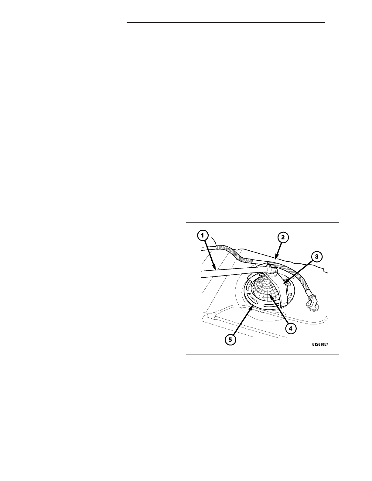
REMOVAL- EXCEPT DIESEL
1. Disconnect and separate fuel vent line (1) from fuel fill bezel (2).
Page 35

DR FUEL DELIVERY - GAS 14 - 35
Page 36

14 - 36 FUEL DELIVERY - GAS DR
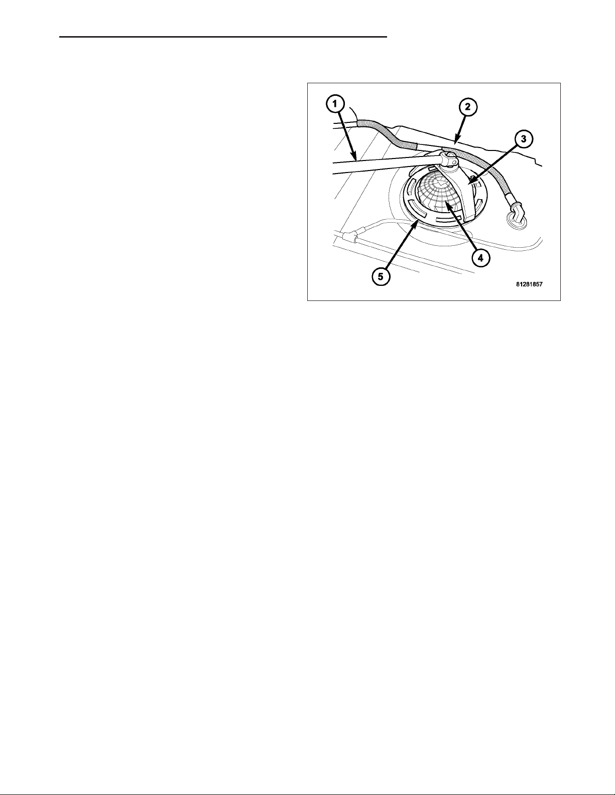
2. Disconnect electrical connector at top of fuel pump module. To disconnect electrical connector: Push upward on
red colored tab to unlock. Push on black colored tab while removing connector.
3. Disconnect necessary emission vent lines from leak pump and EVAP canister (4) and/or (5).
4. Disconnect fuel supply line (2) from fuel pump module (1).
5. Disconnect necessary emission vent lines from check valves (3) and/or (7) at top of tank.
Page 37

DR FUEL DELIVERY - GAS 14 - 37
6. Loosen clamps (3) and disconnect rubber fuel hoses at tank fittings.
7. Support tank with a hydraulic jack.
Page 38

14 - 38 FUEL DELIVERY - GAS DR
8. Remove two fuel tank strap nuts (5) and remove both tank support straps (4).
9. Continue to lower tank for removal.
10. If fuel tank is to be replaced, remove fuel pump module from tank. Refer to Fuel Pump Module Removal/In-
stallation procedures.
INSTALLATION - EXCEPT DIESEL
1. If fuel tank is to be replaced, install fuel pump module into tank. Refer to Fuel Pump Module Removal/
Installation procedures.
2. Disconnect clamps and remove rubber fuel fill hose
and fuel vent hose at fuel fill tube. Install these two
hoses to two fuel tank fittings. Rotate hoses until
paint marks (2) on hoses line up with alignment
marks (1). Tighten both clamps.
Page 39

DR FUEL DELIVERY - GAS 14 - 39
3. Position fuel tank (1) to hydraulic jack.
4. Raise tank (1) until positioned near body.
5. Continue raising tank until positioned snug to body.
6. Install and position both tank support straps (4). Install two fuel tank strap nuts (5) and tighten. Tighten rear
strap nut first. Refer to Torque Specifications.
Page 40

14 - 40 FUEL DELIVERY - GAS DR
7. Connect rubber fill and vent hoses to fuel fill tube and tighten clamps (3).
Page 41

DR FUEL DELIVERY - GAS 14 - 41
Page 42

14 - 42 FUEL DELIVERY - GAS DR
8. Connect electrical connector to top of fuel pump module.
9. Connect necessary emission vent lines to leak pump and EVAP canister (4) and/or (5).
10. Connect fuel supply line (2) to fuel pump module (1).
11. Connect necessary emission vent lines from check valves (3) and/or (7) at top of tank.
12. Connect fuel vent line (1) to fuel fill bezel (2).
13. Fill fuel tank with fuel.
14. Start engine and check for fuel leaks near top of module.
Page 43

DR FUEL DELIVERY - GAS 14 - 43
FILTER - INLET
REMOVAL
The fuel pump inlet filter (strainer) is located on the
bottom of the fuel pump module (1). The fuel pump
module is located inside of fuel tank.
1. Remove fuel tank. Refer to Fuel Tank Removal/Installation.
2. Remove fuel pump module. Refer to Fuel Pump
Module Removal/Installation.
3. Remove filter by carefully prying 2 lock tabs (2) at
bottom of module with 2 screwdrivers. Filter is
snapped to module.
4. Clean bottom of pump module.
INSTALLATION
The fuel pump inlet filter (strainer) is located on the bottom of the fuel pump module. The fuel pump module is
located inside of fuel tank.
1. Snap new filter to bottom of module. Be sure o-ring is in correct position.
2. Install fuel pump module. Refer to Fuel Pump Module Removal/Installation.
3. Install fuel tank. Refer to Fuel Tank Removal/Installation.
Page 44

14 - 44 FUEL INJECTION - GAS DR
FUEL INJECTION - GAS
TABLE OF CONTENTS
page page
PEDAL - ACCELERATOR
REMOVAL ....................................46
INSTALLATION ...............................46
SENSOR-ACCELERATOR PEDAL POSITION
DESCRIPTION ................................47
OPERATION ..................................47
REMOVAL ....................................47
INSTALLATION ...............................48
SENSOR-CRANKSHAFT POSITION
DESCRIPTION
3.7L V-6 ....................................49
4.7L V-8 ....................................49
5.7L V-8 ....................................50
OPERATION
3.7L V-6 ....................................50
4.7L V-8 ....................................51
5.7L V-8 ....................................51
REMOVAL
3.7L V-6 ....................................52
4.7L V-8 ....................................52
5.7L V-8 ....................................53
8.3L - SRT-10 ...............................53
INSTALLATION
3.7L V-6 ....................................54
4.7L V-8 ....................................55
5.7L V-8 ....................................55
8.3L - SRT-10 ...............................55
INJECTOR - FUEL
DESCRIPTION ................................56
OPERATION
FUEL INJECTOR ............................56
PCM OUTPUT ..............................56
REMOVAL
3.7/4.7/ 5.7L ................................57
8.3L - SRT-10 ...............................57
INSTALLATION
3.7/ 4.7/ 5.7L ...............................60
8.3L - SRT-10 ...............................60
RELAY - FUEL PUMP
DESCRIPTION ................................61
OPERATION ..................................61
REMOVAL ....................................61
INSTALLATION ...............................61
MOTOR-IAC
DESCRIPTION
3.7L, 4.7L, 5.7L .............................62
8.3L - SRT-10 ...............................63
OPERATION
3.7L V-6/4.7L V-8 ............................63
REMOVAL
3.7L V-6 ....................................64
4.7L V-8 ....................................65
5.7L V-8 ....................................65
8.3L - SRT-10 ...............................65
INSTALLATION
3.7L V-6 ....................................66
4.7L V-8 ....................................66
5.7L V-8 ....................................66
8.3L - SRT-10 ...............................67
SENSOR - INLET AIR TEMPERATURE
REMOVAL — 8.3L .............................68
INSTALLATION ...............................68
SENSOR-INTAKE AIR TEMPERATURE
DESCRIPTION
3.7L V-6 ....................................69
4.7L V-8 ....................................69
5.7L V-8 ....................................70
OPERATION ..................................70
REMOVAL
3.7L V-6 ....................................71
4.7L V-8 ....................................72
5.7L V-8 ....................................73
INSTALLATION
3.7L V-6 ....................................74
4.7L V-8 ....................................75
5.7L V-8 ....................................75
SENSOR-MAP
DESCRIPTION
3.7L V-6 ....................................76
4.7L V-8 ....................................76
5.7L V-8 ....................................77
8.3L - SRT-10 ...............................77
OPERATION ..................................77
REMOVAL
3.7L V-6 ....................................79
4.7L V-8 ....................................80
5.7L V-8 ....................................80
8.3L-SRT-10 ..............................81
INSTALLATION
3.7L V-6 ....................................81
4.7L V-8 ....................................82
5.7L V-8 ....................................83
8.3L - SRT-10 ...............................83
SENSOR - OXYGEN
DESCRIPTION ................................84
REMOVAL ....................................84
INSTALLATION ...............................85
SWITCH-PTO
DESCRIPTION ................................86
OPERATION ..................................86
THROTTLE BODY
DESCRIPTION ................................87
Page 45

DR FUEL INJECTION - GAS 14 - 45
OPERATION ..................................87
REMOVAL
3.7L V-6 ....................................87
4.7L V-8 ....................................88
5.7L V-8 ....................................88
8.3L - SRT-10 ...............................90
INSTALLATION
3.7L V-6 ....................................92
4.7L V-8 ....................................93
5.7L V-8 ....................................93
8.3L - SRT-10 ...............................94
CABLE - THROTTLE CONTROL
REMOVAL ....................................95
INSTALLATION ...............................97
SENSOR-THROTTLE POSITION
DESCRIPTION
3.7/4.7/5.7L .................................98
8.3L - SRT-10 ...............................98
OPERATION ..................................99
REMOVAL
3.7L V6 ....................................99
4.7L V-8 ...................................100
5.7L V-8 ...................................100
8.3L - SRT-10 ..............................100
INSTALLATION
3.7L V-6 ...................................101
4.7L V-8 ...................................102
8.3L - SRT-10 ..............................103
Page 46

14 - 46 FUEL INJECTION - GAS DR
PEDAL - ACCELERATOR
REMOVAL
The following procedure applies only to vehicles without the Adjustable Pedal Package (code XAP).
The accelerator pedal is serviced as a complete
assembly including the bracket.
The accelerator cable is connected to the upper part
of the accelerator pedal arm by a plastic retainer (clip)
(2). This plastic retainer snaps into the top of the
accelerator pedal arm.
1. From inside the vehicle, hold up accelerator pedal.
Remove plastic cable retainer (clip) and throttle
cable core wire from upper end of accelerator
pedal arm. Plastic cable retainer (clip) snaps into
pedal arm.
2. Remove 2 accelerator pedal mounting bracket
nuts. Remove accelerator pedal assembly.
INSTALLATION
1. Place accelerator pedal assembly over 2 studs.
2. Install and tighten 2 mounting nuts. Refer to Torque Specifications.
3. Slide throttle cable into opening slot in top of pedal arm.
4. Push plastic cable retainer (clip) into accelerator pedal arm opening until it snaps into place.
5. Before starting engine, operate accelerator pedal to check for any binding.
Page 47

DR FUEL INJECTION - GAS 14 - 47
SENSOR-ACCELERATOR PEDAL POSITION
DESCRIPTION
The Accelerator Pedal Position Sensor (APPS) (1) is
located inside the vehicle. It is attached to the accelerator pedal assembly (3). It is used only on 5.7L V-8
gas engines and diesel engines.
OPERATION
The Accelerator Pedal Position Sensor (APPS) provides the Powertrain Control Module (PCM) with two DC voltage
signals which change as the position of the accelerator pedal changes. One of the DC voltage signals will be half
the voltage of the other signal.
REMOVAL
CAUTION: Do not attempt to separate or remove the Accelerator Pedal Position Sensor (APPS) from the
accelerator pedal assembly. The APPS is replaced as an assembly along with the pedal. If sensor is
removed from pedal, its electronic calibration may be destroyed.
1. Disconnect 6–way electrical connector at top of
APPS (2).
2. Remove APPS lower mounting bolt (4) and two
mounting nuts.
3. Remove pedal and APPS assembly from vehicle.
Page 48

14 - 48 FUEL INJECTION - GAS DR
INSTALLATION
CAUTION: Do not attempt to separate or remove the Accelerator Pedal Position Sensor (APPS) from the
accelerator pedal assembly. The APPS is replaced as an assembly along with the pedal. If sensor is
removed from pedal, its electronic calibration may be destroyed.
1. Position pedal and APPS assembly to its mounting
bracket.
2. Connect 6–way electrical connector to top of APPS
(2).
3. Install APPS lower mounting bolt (4) and two
mounting nuts.
4. If necessary, use a Scan Tool to erase any Diagnostic Trouble Codes (DTC’s).
Page 49

DR FUEL INJECTION - GAS 14 - 49
SENSOR-CRANKSHAFT POSITION
DESCRIPTION
3.7L V-6
The Crankshaft Position (CKP) (2) sensor is mounted
into the right rear side of the cylinder block. It is positioned and bolted into a machined hole.
4.7L V-8
The Crankshaft Position (CKP) (1) sensor is mounted
into the right rear side of the cylinder block. It is positioned and bolted into a machined hole.
Page 50

14 - 50 FUEL INJECTION - GAS DR
5.7L V-8
The Crankshaft Position (CKP) (4) sensor is mounted
into the right rear side of the cylinder block. It is positioned and bolted into a machined hole.
OPERATION
3.7L V-6
Engine speed and crankshaft position are provided
through the CKP (Crankshaft Position) sensor. The
sensor generates pulses that are the input sent to the
Powertrain Control Module (PCM). The PCM interprets
the sensor input to determine the crankshaft position.
The PCM then uses this position, along with other
inputs, to determine injector sequence and ignition
timing.
The sensor is a hall effect device combined with an
internal magnet. It is also sensitive to steel within a
certain distance from it.
A tonewheel (targetwheel) (1) is bolted to the engine
crankshaft. This tonewheel has sets of notches (2) at
its outer edge.
The notches cause a pulse to be generated when they
pass under the sensor. The pulses are the input to the
PCM.
Page 51

DR FUEL INJECTION - GAS 14 - 51
4.7L V-8
Engine speed and crankshaft position are provided
through the CKP (Crankshaft Position) sensor. The
sensor generates pulses that are the input sent to the
Powertrain Control Module (PCM). The PCM interprets
the sensor input to determine the crankshaft position.
The PCM then uses this position, along with other
inputs, to determine injector sequence and ignition
timing.
The sensor is a hall effect device combined with an
internal magnet. It is also sensitive to steel within a
certain distance from it.
A tonewheel (1) is bolted to the engine crankshaft.
This tonewheel has sets of notches (2) at its outer
edge.
The notches cause a pulse to be generated when they
pass under the sensor. The pulses are the input to the
PCM.
5.7L V-8
Engine speed and crankshaft position are provided
through the CKP (Crankshaft Position) sensor. The
sensor generates pulses that are the input sent to the
Powertrain Control Module (PCM). The PCM interprets
the sensor input to determine the crankshaft position.
The PCM then uses this position, along with other
inputs, to determine injector sequence and ignition
timing.
The sensor is a hall effect device combined with an
internal magnet. It is also sensitive to steel within a
certain distance from it.
A tonewheel is bolted to the engine crankshaft. This
tonewheel has sets of notches (3) at its outer edge.
The notches cause a pulse to be generated when they
pass under the sensor. The pulses are the input to the
PCM.
Page 52

14 - 52 FUEL INJECTION - GAS DR
REMOVAL
3.7L V-6
The Crankshaft Position (CKP) sensor is mounted into
the right rear side of the cylinder block. It is positioned
and bolted into a machined hole.
1. Raise vehicle.
2. Disconnect sensor electrical connector.
3. Remove sensor mounting bolt (1).
4. Carefully twist sensor (2) from cylinder block.
5. Check condition of sensor O-ring (3).
4.7L V-8
The Crankshaft Position (CKP) sensor is located at
the right-rear side of the engine cylinder block. It is
positioned and bolted into a machined hole in the
engine block.
1. Raise vehicle.
2. Disconnect CKP electrical connector at sensor.
3. Remove CKP mounting bolt (2).
4. Carefully twist sensor (1) from cylinder block.
5. Remove sensor from vehicle.
6. Check condition of sensor O-ring.
Page 53

DR FUEL INJECTION - GAS 14 - 53
5.7L V-8
The Crankshaft Position (CKP) sensor (4) is located at
the right-rear side of the engine cylinder block. It is
positioned and bolted into a machined hole in the
engine block.
1. Raise vehicle.
2. Disconnect CKP electrical connector at sensor.
3. Remove CKP mounting bolt (3).
4. Carefully twist sensor (4) from cylinder block.
5. Remove sensor from vehicle.
6. Check condition of sensor O-ring.
8.3L - SRT-10
The sensor is located at the rear lower passenger side
of motor.
Page 54

14 - 54 FUEL INJECTION - GAS DR
1. Disconnect electrical connector from crankshaft
position sensor.
2. Remove sensor mounting bolt.
3. Pull sensor out. A light tap to top of sensor may
ease removal.
INSTALLATION
3.7L V-6
1. Clean out machined hole in engine block.
2. Apply a small amount of engine oil to sensor O-ring
(3).
3. Install sensor into engine block with a slight rocking
and twisting action.
CAUTION: Before tightening sensor mounting bolt,
be sure sensor is completely flush to cylinder
block. If sensor is not flush, damage to sensor
mounting tang may result.
4. Install mounting bolt and tighten to 28 N·m (21 ft.
lbs.) torque.
5. Connect electrical connector to sensor.
6. Lower vehicle.
Page 55

DR FUEL INJECTION - GAS 14 - 55
4.7L V-8
1. Clean out machined hole in engine block.
2. Apply a small amount of engine oil to sensor
o-ring.
3. Install sensor (1) into engine block with a slight
rocking and twisting action.
CAUTION: Before tightening sensor mounting bolt,
be sure sensor is completely flush to cylinder
block. If sensor is not flush, damage to sensor
mounting tang may result.
4. Install mounting bolt and tighten to 28 N·m (21 ft.
lbs.) torque.
5. Connect electrical connector to sensor.
6. Lower vehicle.
5.7L V-8
1. Clean out machined hole in engine block.
2. Apply a small amount of engine oil to sensor
o-ring.
3. Install sensor (4) into engine block with a slight
rocking and twisting action.
CAUTION: Before tightening sensor mounting bolt,
be sure sensor is completely flush to cylinder
block. If sensor is not flush, damage to sensor
mounting tang may result.
4. Install mounting bolt (3) and tighten to 28 N·m (21
ft. lbs.) torque.
5. Connect electrical connector to sensor.
6. Lower vehicle.
8.3L - SRT-10
1. Slide the sensor into the hole.
2. Install and tighten the mounting bolt to 11 N·m (95 in. lbs.) torque.
3. Connect the electrical connector to the sensor and lock.
Page 56

14 - 56 FUEL INJECTION - GAS DR
INJECTOR - FUEL
DESCRIPTION
An individual fuel injector (1) is used for each individual cylinder.
OPERATION
FUEL INJECTOR
The top (fuel entry) end of the injector (1) is attached
into an opening on the fuel rail.
The fuel injectors are electrical solenoids. The injector
contains a pintle that closes off an orifice at the nozzle
end. When electric current is supplied to the injector,
the armature and needle move a short distance
against a spring, allowing fuel to flow out the orifice.
Because the fuel is under high pressure, a fine spray
is developed in the shape of a pencil stream. The
spraying action atomizes the fuel, adding it to the air
entering the combustion chamber.
The nozzle (outlet) ends of the injectors are positioned
into openings in the intake manifold just above the
intake valve ports of the cylinder head. The engine
wiring harness connector for each fuel injector is
equipped with an attached numerical tag (INJ 1, INJ 2 etc.). This is used to identify each fuel injector.
The injectors are energized individually in a sequential order by the Powertrain Control Module (PCM). The PCM will
adjust injector pulse width by switching the ground path to each individual injector on and off. Injector pulse width is
the period of time that the injector is energized. The PCM will adjust injector pulse width based on various inputs it
receives.
Battery voltage is supplied to the injectors through the ASD relay.
The PCM determines injector pulse width based on various inputs.
PCM OUTPUT
The nozzle ends of the injectors are positioned into openings in the intake manifold just above the intake valve ports
of the cylinder head. The engine wiring harness connector for each fuel injector is equipped with an attached
numerical tag (INJ 1, INJ 2 etc.). This is used to identify each fuel injector with its respective cylinder number.
The injectors are energized individually in a sequential order by the Powertrain Control Module (PCM). The PCM will
adjust injector pulse width by switching the ground path to each individual injector on and off. Injector pulse width is
the period of time that the injector is energized. The PCM will adjust injector pulse width based on various inputs it
receives.
Page 57

DR FUEL INJECTION - GAS 14 - 57
Battery voltage (12 volts +) is supplied to the injectors through the ASD relay. The ASD relay will shut-down the 12
volt power source to the fuel injectors if the PCM senses the ignition is on, but the engine is not running. This
occurs after the engine has not been running for approximately 1.8 seconds.
The PCM determines injector on-time (pulse width) based on various inputs.
REMOVAL
3.7/4.7/ 5.7L
1. Remove fuel rail. (Refer to 14 - FUEL SYSTEM/
FUEL DELIVERY/FUEL RAIL - REMOVAL)
2. Disconnect clip(s) that retain fuel injector(s) to fuel
rail (2).
8.3L - SRT-10
1. Release fuel system pressure. Refer to Fuel Pressure Release Procedure in this section.
2. Remove the battery cover and disconnect negative
battery cable.
3. Remove the air cleaner assembly, refer to the
Engine/Air Intake System/Air Cleaner Housing for
more information.
4. Disconnect the electrical connector to the MAP
sensor and Coolant Temperature sensor.
Page 58

14 - 58 FUEL INJECTION - GAS DR
5. Disconnect the electrical connector to the TPS and
Idle Air Control.
6. Remove the wiring harness from the wiring clips
under thew throttle body.
7. Disconnect the electrical connector from the fuel
injectors.
Page 59

DR FUEL INJECTION - GAS 14 - 59
8. Disconnect the fuel line quick connector.
9. Remove the bolts for the fuel rail.
10. Pull fuel rail and injectors straight up and out of
the intake manifold.
11. Move the fuel rail forward and out from under the
intake manifold and throttle body.
Page 60

14 - 60 FUEL INJECTION - GAS DR
12. Remove the fuel injector from the fuel rail.
INSTALLATION
3.7/ 4.7/ 5.7L
1. Install fuel injector(s) into fuel rail assembly and install retaining clip(s).
2. If same injector(s) is being reinstalled, install new O-ring(s).
3. Apply a small amount of clean engine oil to each injector O-ring. This will aid in installation.
4. Install fuel rail. (Refer to 14 - FUEL SYSTEM/FUEL DELIVERY/FUEL RAIL - INSTALLATION)
5. Start engine and check for fuel leaks.
8.3L - SRT-10
1. Install the fuel injectors to the fuel rail.
2. Install fuel rail under throttle body.
3. Apply a light coating of clean engine oil to the O-ring on the nozzle end of each injector.
4. Insert fuel injector nozzles into openings in intake manifold. Seat the injectors in place. Tighten fuel rail bolts to
12 N·m (105 in. lbs.).
5. Attach electrical connectors to fuel injectors.
6. Connect the electrical connector to the MAP sensor and Coolant Temperature sensor.
7. Connect the electrical connector to the TPS and Idle Air Control.
8. Install the wiring harness to the wiring clips under the throttle body.
9. Connect fuel supply tube to fuel rail. Refer to Quick Connect Fittings in the Fuel Delivery section
10. Install the negative battery cable and install the battery cover.
11. Install the air cleaner assembly, refer to the Engine/Air Intake System/Air Cleaner Housing for more information.
12. Use the DRBIIIT scan tool ASD Fuel System Test to pressurize the fuel system. Check for leaks.
Page 61

DR FUEL INJECTION - GAS 14 - 61
RELAY - FUEL PUMP
DESCRIPTION
The 5–pin, 12–volt, fuel pump relay is located in the Power Distribution Center (PDC). Refer to the label on the PDC
cover for relay location.
OPERATION
The Powertrain Control Module (PCM) energizes the electric fuel pump through the fuel pump relay. The fuel pump
relay is energized by first applying battery voltage to it when the ignition key is turned ON, and then applying a
ground signal to the relay from the PCM.
Whenever the ignition key is turned ON, the electric fuel pump will operate. But, the PCM will shut-down the ground
circuit to the fuel pump relay in approximately 1–3 seconds unless the engine is operating or the starter motor is
engaged.
REMOVAL
The fuel pump relay is located in the Power Distribution Center (PDC) (2). Refer to label on PDC cover for
relay location.
1. Remove PDC cover.
2. Remove relay from PDC.
3. Check condition of relay terminals and PDC connector terminals for damage or corrosion. Repair if
necessary before installing relay.
4. Check for pin height (pin height should be the
same for all terminals within the PDC connector).
Repair if necessary before installing relay.
INSTALLATION
The fuel pump relay is located in the Power Distribution Center (PDC). Refer to label on PDC cover for relay location.
1. Install relay to PDC.
2. Install cover to PDC.
Page 62

14 - 62 FUEL INJECTION - GAS DR
MOTOR-IAC
DESCRIPTION
3.7L, 4.7L, 5.7L
3.7L: The IAC stepper motor (3) is mounted to the
throttle body. It regulates the amount of air bypassing
the control of the throttle plate. As engine loads and
ambient temperatures change, engine rpm changes. A
pintle on the IAC stepper motor protrudes into a passage in the throttle body, controlling air flow through
the passage. The IAC is controlled by the Powertrain
Control Module (PCM) to maintain the target engine
idle speed.
4.7L: The IAC stepper motor (3) is mounted to the
throttle body. It regulates the amount of air bypassing
the control of the throttle plate. As engine loads and
ambient temperatures change, engine rpm changes. A
pintle on the IAC stepper motor protrudes into a passage in the throttle body, controlling air flow through
the passage. The IAC is controlled by the Powertrain
Control Module (PCM) to maintain the target engine
idle speed.
5.7L: A separate IAC motor is not used with the 5.7L
V-8 engine.
Page 63

DR FUEL INJECTION - GAS 14 - 63
8.3L - SRT-10
The idle air control motor is mounted at the front right
of the intake manifold.
OPERATION
3.7L V-6/4.7L V-8
A separate IAC motor is not used with the 5.7L V-8 engine.
At idle, engine speed can be increased by retracting the IAC motor pintle and allowing more air to pass through the
port, or it can be decreased by restricting the passage with the pintle and diminishing the amount of air bypassing
the throttle plate.
The IAC is called a stepper motor because it is moved (rotated) in steps, or increments. Opening the IAC opens an
air passage around the throttle blade which increases RPM.
The PCM uses the IAC motor to control idle speed (along with timing) and to reach a desired MAP during decel
(keep engine from stalling).
The IAC motor has 4 wires with 4 circuits. Two of the wires are for 12 volts and ground to supply electrical current
to the motor windings to operate the stepper motor in one direction. The other 2 wires are also for 12 volts and
ground to supply electrical current to operate the stepper motor in the opposite direction.
To make the IAC go in the opposite direction, the PCM just reverses polarity on both windings. If only 1 wire is
open, the IAC can only be moved 1 step (increment) in either direction. To keep the IAC motor in position when no
movement is needed, the PCM will energize both windings at the same time. This locks the IAC motor in place.
In the IAC motor system, the PCM will count every step that the motor is moved. This allows the PCM to determine
the motor pintle position. If the memory is cleared, the PCM no longer knows the position of the pintle. So at the
first key ON, the PCM drives the IAC motor closed, regardless of where it was before. This zeros the counter. From
this point the PCM will back out the IAC motor and keep track of its position again.
When engine rpm is above idle speed, the IAC is used for the following:
• Off-idle dashpot (throttle blade will close quickly but idle speed will not stop quickly)
• Deceleration air flow control
• A/C compressor load control (also opens the passage slightly before the compressor is engaged so that the
engine rpm does not dip down when the compressor engages)
• Power steering load control
The PCM can control polarity of the circuit to control direction of the stepper motor.
IAC Stepper Motor Program: The PCM is also equipped with a memory program that records the number of steps
the IAC stepper motor most recently advanced to during a certain set of parameters. For example: The PCM was
attempting to maintain a 1000 rpm target during a cold start-up cycle. The last recorded number of steps for that
may have been 125. That value would be recorded in the memory cell so that the next time the PCM recognizes the
Page 64

14 - 64 FUEL INJECTION - GAS DR
identical conditions, the PCM recalls that 125 steps were required to maintain the target. This program allows for
greater customer satisfaction due to greater control of engine idle.
Another function of the memory program, which occurs when the power steering switch (if equipped), or the A/C
request circuit, requires that the IAC stepper motor control engine rpm, is the recording of the last targeted steps
into the memory cell. The PCM can anticipate A/C compressor loads. This is accomplished by delaying compressor
operation for approximately 0.5 seconds until the PCM moves the IAC stepper motor to the recorded steps that
were loaded into the memory cell. Using this program helps eliminate idle-quality changes as loads change. Finally,
the PCM incorporates a 9No-Load9 engine speed limiter of approximately 1800 - 2000 rpm, when it recognizes that
the TPS is indicating an idle signal and IAC motor cannot maintain engine idle.
A (factory adjusted) set screw is used to mechanically limit the position of the throttle body throttle plate. Never
attempt to adjust the engine idle speed using this screw. All idle speed functions are controlled by the IAC
motor through the PCM.
REMOVAL
3.7L V-6
The Idle Air Control (IAC) motor (3) is located on the
side of the throttle body.
1. Remove air resonator box at throttle body.
2. Disconnect electrical connector from IAC motor.
3. Remove two mounting bolts (screws) (4).
4. Remove IAC motor from throttle body.
Page 65

DR FUEL INJECTION - GAS 14 - 65
4.7L V-8
The Idle Air Control (IAC) motor (3) is located on the
side of the throttle body.
1. Remove air resonator box at throttle body.
2. Disconnect electrical connector from IAC motor.
3. Remove two mounting bolts (screws).
4. Remove IAC motor from throttle body.
5.7L V-8
The IAC motor is not serviceable on the 5.7L V-8 engine.
8.3L - SRT-10
The IAC motor is inserted into a housing at the front of the intake manifold. The IAC motor and housing are serviced together.
1. Remove housing to manifold screws. Remove IAC motor and housing.
2. Disconnect the electrical connector from IAC motor.
Page 66

14 - 66 FUEL INJECTION - GAS DR
INSTALLATION
3.7L V-6
The Idle Air Control (IAC) motor (3) is located on the
side of the throttle body.
1. Install IAC motor to throttle body.
2. Install and tighten two mounting bolts (screws) to 7
N·m (60 in. lbs.) torque.
3. Install electrical connector.
4. Install air resonator to throttle body.
4.7L V-8
The Idle Air Control (IAC) motor (3) is located on the
side of the throttle body.
1. Install IAC motor to throttle body.
2. Install and tighten two mounting bolts (screws) to 7
N·m (60 in. lbs.) torque.
3. Install electrical connector.
4. Install air resonator to throttle body.
5.7L V-8
The IAC motor is not serviceable on the 5.7L V-8 engine.
Page 67

DR FUEL INJECTION - GAS 14 - 67
8.3L - SRT-10
The IAC motor is inserted into a housing at the front of the intake manifold. The IAC motor and housing are serviced together.
1. Attach electrical connector to IAC motor.
2. Install IAC motor into and housing on manifold. Tighten mounting screws to 4 N·m (35 in. lbs.) torque.
Page 68

14 - 68 FUEL INJECTION - GAS DR
SENSOR - INLET AIR TEMPERATURE
REMOVAL — 8.3L
NOTE: Take care not to damage the thermister pill
when removing the sensor.
1. Remove the battery cover and disconnect the neg-
ative battery cable.
2. Disconnect the electrical connector from the inlet
temperature sensor.
3. Remove sensor from inlet hose.
INSTALLATION
NOTE: Take care not to damage the open thermister pill when installing the sensor.
1. Install sensor , use a little water to aid in insertion
of sensor.
2. Make sure that the rib on the sensor matches up
with the rib on the inlet hose. The thermister pill
should be in direct contact with the inlet air stream.
3. Connect the electrical connector.
4. Connect the negative battery cable and install bat-
tery cover.
Page 69

DR FUEL INJECTION - GAS 14 - 69
SENSOR-INTAKE AIR TEMPERATURE
DESCRIPTION
3.7L V-6
The 2-wire Intake Manifold Air Temperature (IAT) sensor (1) is installed in the intake manifold with the sensor element extending into the air stream.
The IAT sensor is a two-wire Negative Thermal Coefficient (NTC) sensor. Meaning, as intake manifold temperature increases, resistance (voltage) in the sensor
decreases. As temperature decreases, resistance
(voltage) in the sensor increases.
4.7L V-8
The 2-wire Intake Manifold Air Temperature (IAT) sensor (3) is installed in the intake manifold with the sensor element extending into the air stream.
The IAT sensor is a two-wire Negative Thermal Coefficient (NTC) sensor. Meaning, as intake manifold temperature increases, resistance (voltage) in the sensor
decreases. As temperature decreases, resistance
(voltage) in the sensor increases.
Page 70

14 - 70 FUEL INJECTION - GAS DR
5.7L V-8
The 2-wire Intake Manifold Air Temperature (IAT) sensor is installed in the intake manifold (2) with the sensor element extending into the air stream.
The IAT sensor is a two-wire Negative Thermal Coefficient (NTC) sensor. Meaning, as intake manifold temperature increases, resistance (voltage) in the sensor
decreases. As temperature decreases, resistance
(voltage) in the sensor increases.
OPERATION
The IAT sensor provides an input voltage to the Powertrain Control Module (PCM) indicating the density of the air
entering the intake manifold based upon intake manifold temperature. At key-on, a 5–volt power circuit is supplied
to the sensor from the PCM. The sensor is grounded at the PCM through a low-noise, sensor-return circuit.
The PCM uses this input to calculate the following:
• Injector pulse-width
• Adjustment of spark timing (to help prevent spark knock with high intake manifold air-charge temperatures)
The resistance values of the IAT sensor is the same as for the Engine Coolant Temperature (ECT) sensor.
Page 71

DR FUEL INJECTION - GAS 14 - 71
REMOVAL
3.7L V-6
The intake manifold air temperature (IAT) sensor is
installed into the left side of intake manifold plenum.
1. Disconnect electrical connector from IAT sensor.
2. Clean dirt from intake manifold at sensor base.
3. Gently lift on small plastic release tab (3) and
rotate sensor about 1/4 turn counterclockwise for
removal.
4. Check condition of sensor O-ring.
Page 72

14 - 72 FUEL INJECTION - GAS DR
4.7L V-8
The intake manifold air temperature (IAT) sensor (3) is
installed into the left side of intake manifold plenum.
1. Disconnect electrical connector from IAT sensor.
2. Clean dirt from intake manifold at sensor base.
3. Gently lift on small plastic release tab (3) and
rotate sensor about 1/4 turn counterclockwise for
removal.
4. Check condition of sensor O-ring.
Page 73

DR FUEL INJECTION - GAS 14 - 73
5.7L V-8
The intake manifold air temperature (IAT) sensor (2) is
installed into the front of the intake manifold air box
plenum.
1. Disconnect electrical connector (2) from IAT sensor.
2. Clean dirt from intake manifold at sensor base.
Page 74

14 - 74 FUEL INJECTION - GAS DR
3. Gently lift on small plastic release tab (3) and
rotate sensor about 1/4 turn counterclockwise for
removal.
4. Check condition of sensor O-ring.
INSTALLATION
3.7L V-6
The intake manifold air temperature (IAT) sensor (1) is
installed into the left side of intake manifold plenum.
1. Check condition of sensor O-ring.
2. Clean sensor mounting hole in intake manifold.
3. Position sensor into intake manifold and rotate
clockwise until past release tab (2).
4. Install electrical connector.
Page 75

DR FUEL INJECTION - GAS 14 - 75
4.7L V-8
The intake manifold air temperature (IAT) sensor (3) is
installed into the left side of intake manifold plenum.
1. Check condition of sensor O-ring.
2. Clean sensor mounting hole in intake manifold.
3. Position sensor into intake manifold and rotate
clockwise until past release tab.
4. Install electrical connector.
5.7L V-8
The intake manifold air temperature (IAT) sensor (2) is
installed into the front of the intake manifold air box
plenum.
1. Check condition of sensor O-ring.
2. Clean sensor mounting hole in intake manifold.
3. Position sensor into intake manifold and rotate
clockwise until past release tab.
4. Install electrical connector.
Page 76

14 - 76 FUEL INJECTION - GAS DR
SENSOR-MAP
DESCRIPTION
3.7L V-6
The Manifold Absolute Pressure (MAP) sensor (2) is
mounted into the front of the intake manifold with 2
screws.
4.7L V-8
The Manifold Absolute Pressure (MAP) sensor (1) is
mounted into the front of the intake manifold with 2
screws.
Page 77

DR FUEL INJECTION - GAS 14 - 77
5.7L V-8
The Manifold Absolute Pressure (MAP) sensor is
mounted to the front of the intake manifold air plenum
box.
8.3L - SRT-10
The MAP sensor (2) mounts to the drivers side intake
manifold plenum.
OPERATION
The MAP sensor is used as an input to the Powertrain Control Module (PCM). It contains a silicon based sensing
unit to provide data on the manifold vacuum that draws the air/fuel mixture into the combustion chamber. The PCM
requires this information to determine injector pulse width and spark advance. When manifold absolute pressure
(MAP) equals Barometric pressure, the pulse width will be at maximum.
A 5 volt reference is supplied from the PCM and returns a voltage signal to the PCM that reflects manifold pressure.
The zero pressure reading is 0.5V and full scale is 4.5V. For a pressure swing of 0–15 psi, the voltage changes
4.0V. To operate the sensor, it is supplied a regulated 4.8 to 5.1 volts. Ground is provided through the low-noise,
sensor return circuit at the PCM.
The MAP sensor input is the number one contributor to fuel injector pulse width. The most important function of the
MAP sensor is to determine barometric pressure. The PCM needs to know if the vehicle is at sea level or at a
Page 78

14 - 78 FUEL INJECTION - GAS DR
higher altitude, because the air density changes with altitude. It will also help to correct for varying barometric pressure. Barometric pressure and altitude have a direct inverse correlation; as altitude goes up, barometric goes down.
At key-on, the PCM powers up and looks at MAP voltage, and based upon the voltage it sees, it knows the current
barometric pressure (relative to altitude). Once the engine starts, the PCM looks at the voltage again, continuously
every 12 milliseconds, and compares the current voltage to what it was at key-on. The difference between current
voltage and what it was at key-on, is manifold vacuum.
During key-on (engine not running) the sensor reads (updates) barometric pressure. A normal range can be
obtained by monitoring a known good sensor.
As the altitude increases, the air becomes thinner (less oxygen). If a vehicle is started and driven to a very different
altitude than where it was at key-on, the barometric pressure needs to be updated. Any time the PCM sees Wide
Open Throttle (WOT), based upon Throttle Position Sensor (TPS) angle and RPM, it will update barometric pressure
in the MAP memory cell. With periodic updates, the PCM can make its calculations more effectively.
The PCM uses the MAP sensor input to aid in calculating the following:
• Manifold pressure
• Barometric pressure
• Engine load
• Injector pulse-width
• Spark-advance programs
• Shift-point strategies (certain automatic transmissions only)
• Idle speed
• Decel fuel shutoff
The MAP sensor signal is provided from a single piezoresistive element located in the center of a diaphragm. The
element and diaphragm are both made of silicone. As manifold pressure changes, the diaphragm moves causing
the element to deflect, which stresses the silicone. When silicone is exposed to stress, its resistance changes. As
manifold vacuum increases, the MAP sensor input voltage decreases proportionally. The sensor also contains electronics that condition the signal and provide temperature compensation.
The PCM recognizes a decrease in manifold pressure by monitoring a decrease in voltage from the reading stored
in the barometric pressure memory cell. The MAP sensor is a linear sensor; meaning as pressure changes, voltage
changes proportionately. The range of voltage output from the sensor is usually between 4.6 volts at sea level to as
low as 0.3 volts at 26 in. of Hg. Barometric pressure is the pressure exerted by the atmosphere upon an object. At
sea level on a standard day, no storm, barometric pressure is approximately 29.92 in Hg. For every 100 feet of
altitude, barometric pressure drops 0.10 in. Hg. If a storm goes through, it can change barometric pressure from
what should be present for that altitude. You should know what the average pressure and corresponding barometric
pressure is for your area.
Page 79

DR FUEL INJECTION - GAS 14 - 79
REMOVAL
3.7L V-6
The Manifold Absolute Pressure (MAP) sensor is
mounted into the front of the intake manifold
An O-ring (2) is used to seal the sensor to the intake
manifold.
1. Disconnect electrical connector at sensor.
2. Clean area around MAP sensor.
3. Remove 2 sensor mounting screws.
4. Remove MAP sensor from intake manifold.
5. Check condition of sensor O-ring.
Page 80

14 - 80 FUEL INJECTION - GAS DR
4.7L V-8
The MAP sensor (3) is located on the front of the
intake manifold. An O-ring seals the sensor to the
intake manifold.
1. Disconnect electrical connector at sensor.
2. Clean area around MAP sensor.
3. Remove 2 sensor mounting bolts.
4. Remove MAP sensor from intake manifold.
5. Check condition of sensor O-ring.
5.7L V-8
The Manifold Absolute Pressure (MAP) sensor is
mounted to the front of the intake manifold air plenum
box.
Page 81

DR FUEL INJECTION - GAS 14 - 81
1. Disconnect electrical connector at sensor by sliding
release lock out. Press down on lock tab for
removal.
2. Rotate sensor (3) 1/4 turn counterclockwise for
removal.
3. Check condition of sensor O-ring.
8.3 L - SRT-10
The manifold absolute pressure sensor is mounted on the drivers side of the intake manifold.
1. Disconnect the electrical connector from the MAP sensor.
2. Remove MAP sensor mounting screws.
INSTALLATION
3.7L V-6
The Manifold Absolute Pressure (MAP) sensor is
mounted into the front of the intake manifold.
Page 82

14 - 82 FUEL INJECTION - GAS DR
An O-ring (2) is used to seal the sensor to the intake
manifold.
1. Clean MAP sensor mounting hole at intake mani-
fold.
2. Check MAP sensor O-ring seal for cuts or tears.
3. Position sensor into manifold.
4. Install MAP sensor mounting bolts (screws). (Refer
to 14 - FUEL SYSTEM/FUEL DELIVERY - SPECIFICATIONS)
5. Connect electrical connector.
4.7L V-8
The MAP sensor is located on the front of the intake
manifold.
Page 83

DR FUEL INJECTION - GAS 14 - 83
An O-ring (2) seals the sensor to the intake manifold.
1. Clean MAP sensor mounting hole at intake mani-
fold.
2. Check MAP sensor O-ring seal for cuts or tears.
3. Position sensor into manifold.
4. Install MAP sensor mounting bolts (screws). (Refer
to 14 - FUEL SYSTEM/FUEL DELIVERY - SPECIFICATIONS)
5. Connect electrical connector.
5.7L V-8
The Manifold Absolute Pressure (MAP) sensor (1) is
mounted to the front of the intake manifold air plenum
box.
1. Clean MAP sensor mounting hole at intake mani-
fold.
2. Check MAP sensor O-ring seal for cuts or tears.
3. Position sensor into manifold.
4. Rotate sensor 1/4 turn clockwise for installation.
5. Connect electrical connector.
8.3L - SRT-10
1. Install the MAP sensor to the intake manifold.
2. Install MAP sensor mounting screws and tighten mounting screws to 4 N·m (35 in. lbs.).
3. Connect the electrical connector to the MAP sensor.
Page 84

14 - 84 FUEL INJECTION - GAS DR
SENSOR - OXYGEN
DESCRIPTION
The Oxygen Sensors (O2S) are attached to, and protrude into the vehicle exhaust system. Depending on the
engine or emission package, the vehicle may use a total of either 2 or 4 sensors.
Federal Emission Packages : Two sensors are used: upstream (referred to as 1/1) and downstream (referred to as
1/2). With this emission package, the upstream sensor (1/1) is located just before the main catalytic convertor. The
downstream sensor (1/2) is located just after the main catalytic convertor.
California Emission Packages: On this emissions package, 4 sensors are used: 2 upstream (referred to as 1/1
and 2/1) and 2 downstream (referred to as 1/2 and 2/2). With this emission package, the right upstream sensor (2/1)
is located in the right exhaust downpipe just before the mini-catalytic convertor. The left upstream sensor (1/1) is
located in the left exhaust downpipe just before the mini-catalytic convertor. The right downstream sensor (2/2) is
located in the right exhaust downpipe just after the mini-catalytic convertor, and before the main catalytic convertor.
The left downstream sensor (1/2) is located in the left exhaust downpipe just after the mini-catalytic convertor, and
before the main catalytic convertor.
REMOVAL
CAUTION: Never apply any type of grease to the oxygen sensor electrical connector, or attempt any soldering of the sensor wiring harness.
WARNING: The exhaust manifold, exhaust pipes and catalytic converter become very hot during engine
operation. Allow engine to cool before removing oxygen sensor.
1. Raise and support vehicle.
2. Disconnect wire connector from O2S sensor.
CAUTION: When disconnecting sensor electrical
connector, do not pull directly on wire going into
sensor.
3. Remove O2S sensor with an oxygen sensor
removal and installation tool.
4. Clean threads in exhaust pipe using appropriate
tap.
Page 85

DR FUEL INJECTION - GAS 14 - 85
INSTALLATION
Threads of new oxygen sensors are factory coated with anti-seize compound to aid in removal. DO NOT add any
additional anti-seize compound to threads of a new oxygen sensor.
1. Install O2S sensor. Tighten to 30 N·m (22 ft. lbs.) torque.
2. Connect O2S sensor wire connector.
3. Lower vehicle.
Page 86

14 - 86 FUEL INJECTION - GAS DR
SWITCH-PTO
DESCRIPTION
This Powertrain Control Module (PCM) input is used only on models equipped with aftermarket Power Take Off
(PTO) units.
OPERATION
The input is used only to tell the PCM (or ECM-Diesel) that the PTO has been engaged. The PCM (or ECM) will
disable (temporarily shut down) certain OBD II diagnostic trouble codes when the PTO is engaged.
JTEC and NGC Engine Controllers: When the aftermarket PTO switch has been engaged, a 12V + signal is sent
through circuit G113 to PCM pin A13. The PCM will then sense and determine that the PTO has been activated.
CM 845 or CM 848 Diesel Engine Controllers: When the aftermarket PTO switch has been engaged, a 12V +
signal is sent through circuit G113 to ECM pin B38. The ECM will then sense and determine that the PTO has been
activated.
Page 87

DR FUEL INJECTION - GAS 14 - 87
THROTTLE BODY
DESCRIPTION
The throttle body is located on the intake manifold. Fuel does not enter the intake manifold through the throttle body.
Fuel is sprayed into the manifold by the fuel injectors.
OPERATION
Filtered air from the air cleaner enters the intake manifold through the throttle body. The throttle body contains an air
control passage controlled by an Idle Air Control (IAC) motor. The air control passage is used to supply air for idle
conditions. A throttle valve (plate) is used to supply air for above idle conditions.
5.7L V-8 Engine:
The throttle body on the 5.7L engine is an electrically controlled unit. A mechanical cable is not used to connect the
throttle body to the accelerator pedal. The Accelerator Pedal Position Sensor (APPS) along with inputs from other
sensors sets the throttle blade to pre-determined positions.
Except 5.7L V-8 Engine:
Certain sensors are attached to the throttle body. The accelerator pedal cable, speed control cable and transmission
control cable (when equipped) are connected to the throttle body linkage arm.
A (factory adjusted) set screw is used to mechanically limit the position of the throttle body throttle plate. Never
attempt to adjust the engine idle speed using this screw. All idle speed functions are controlled by the PCM.
REMOVAL
3.7L V-6
A (factory adjusted) set screw is used to mechanically
limit the position of the throttle body throttle plate.
Never attempt to adjust the engine idle speed
using this screw. All idle speed functions are con-
trolled by the Powertrain Control Module (PCM).
1. Remove air cleaner tube at throttle body.
2. Disconnect throttle body electrical connectors at
IAC motor and TPS.
3. Remove all control cables from throttle body (lever)
arm. Refer to the Accelerator Pedal and Throttle
Cable section for removal/installation procedures.
4. Disconnect necessary vacuum lines at throttle
body.
5. Remove 3 throttle body mounting bolts (2).
6. Remove throttle body from intake manifold.
Page 88

14 - 88 FUEL INJECTION - GAS DR
7. Check condition of old throttle body-to-intake man-
ifold O-ring.
4.7L V-8
1. Remove air duct and air resonator box at throttle
body.
2. Disconnect throttle body electrical connectors at
IAC motor and TPS.
3. Remove vacuum line at throttle body.
4. Remove all control cables from throttle body (lever)
arm. Refer to Accelerator Pedal and Throttle Cable.
5. Remove three throttle body mounting bolts (1).
6. Remove throttle body from intake manifold.
5.7L V-8
CAUTION: Do not use spray (carb) cleaners on any part of the throttle body. Do not apply silicone lubricants to any part of the throttle body.
Page 89

DR FUEL INJECTION - GAS 14 - 89
1. Remove air duct and air resonator box at throttle
body.
2. Disconnect electrical connector (2) at throttle body.
3. Remove 4 throttle body mounting bolts (4).
4. Remove throttle body from intake manifold.
5. Check condition of throttle body O-ring (2).
6. If the throttle body has been changed, the following
procedure must be performed:
a. Disconnect negative battery cable from battery.
Leave cable disconnected for approximately 90
seconds.
b. Reconnect cable to battery.
c. Turn ignition switch ON, but do not crank
engine.
d. Leave ignition switch ON for a minimum of 10
seconds. This will allow PCM to learn throttle
body electrical parameters.
Page 90

14 - 90 FUEL INJECTION - GAS DR
8.3L - SRT-10
1. Remove the throttle cable.
2. Remove the battery cover and disconnect the negative battery cable.
3. Remove the air cleaner assembly, refer to the
Engine/Air Intake System/Air Cleaner Housing for
more information.
4. Disconnect the TPS electrical connector.
Page 91

DR FUEL INJECTION - GAS 14 - 91
5. Remove the throttle body bolts.
6. Remove the throttle body wiring clips.
7. Remove the throttle body.
Page 92

14 - 92 FUEL INJECTION - GAS DR
INSTALLATION
3.7L V-6
1. Check condition of throttle body-to-intake manifold
O-ring (2). Replace as necessary.
2. Clean mating surfaces of throttle body and intake
manifold.
3. Install throttle body-to-intake manifold o-ring.
4. Install throttle body to intake manifold.
5. Install three mounting bolts (2). Tighten bolts to 12
N·m (105 in. lbs.) torque.
6. Install control cables.
7. Install electrical connectors.
8. Install necessary vacuum lines.
9. Install air plenum.
Page 93

DR FUEL INJECTION - GAS 14 - 93
4.7L V-8
1. Clean throttle body-to-intake manifold o-ring.
2. Clean mating surfaces of throttle body and intake
manifold.
3. Install throttle body to intake manifold by positioning throttle body to manifold alignment pins.
4. Install three mounting bolts (1). Tighten bolts to 12
N·m (105 in. lbs.) torque.
5. Install control cables.
6. Install vacuum line to throttle body.
7. Install electrical connectors.
8. Install air plenum.
5.7L V-8
CAUTION: Do not use spray (carb) cleaners on any part of the throttle body. Do not apply silicone lubricants to any part of the throttle body.
1. Clean and check condition of throttle body-to-intake
manifold O-ring (2).
2. Clean mating surfaces of throttle body and intake
manifold.
3. Install throttle body to intake manifold by positioning throttle body to manifold alignment pins.
Page 94

14 - 94 FUEL INJECTION - GAS DR
4. Install 4 mounting bolts. (Refer to 14 - FUEL SYSTEM/FUEL DELIVERY - SPECIFICATIONS)
5. Install electrical connector.
6. Install air plenum.
7. If the throttle body has been changed, the fol-
lowing procedure must be performed:
a. Disconnect negative battery cable from battery.
Leave cable disconnected for approximately 90
seconds.
b. Reconnect cable to battery.
c. Turn ignition switch ON, but do not crank
engine.
d. Leave ignition switch ON for a minimum of 10
seconds. This will allow PCM to learn throttle
body electrical parameters.
8.3L - SRT-10
1. Mount throttle body and wiring clips , tighten bolts to 12 N.m (105 in. lbs.).
2. Connect electrical connector to throttle position sensor.
3. Install the throttle cable.
4. Install the air cleaner housing, refer to Engine/Air Intake System/Air Cleaner Housing.
5. Connect the negative battery cable and install the battery cover.
Page 95

DR FUEL INJECTION - GAS 14 - 95
CABLE - THROTTLE CONTROL
REMOVAL
3.7L V-6
CAUTION: Be careful not to damage or kink cable core wire (within cable sheathing) while servicing accelerator pedal or throttle cable.
1. From inside vehicle, hold up accelerator pedal.
Remove plastic cable retainer (clip) and throttle
cable core wire from upper end of pedal arm. Plastic cable retainer snaps into top of pedal arm.
2. Remove cable core wire at pedal arm.
3. From inside vehicle, remove metal clip holding
cable to dashpanel.
4. Remove air resonator box at throttle body.
5. Unsnap cable from dashpanel routing clip.
6. Remove cable housing from dash panel and pull
into engine compartment.
7. Hold throttle in wide open position. While held in
this position, slide throttle cable pin (1) from throttle
body bellcrank.
8. Using a pick or small screwdriver (3), press release
tab (2) to release plastic (4) cable mount from
bracket. Press on tab only enough to release
cable from bracket. If tab is pressed too much,
it will be broken. Slide plastic mount towards right
side of vehicle to remove throttle cable from throttle
body bracket.
9. Remove throttle cable from vehicle.
4.7L V-8
CAUTION: Be careful not to damage or kink cable core wire (within cable sheathing) while servicing accelerator pedal or throttle cable.
Page 96

14 - 96 FUEL INJECTION - GAS DR
1. From inside vehicle, hold up accelerator pedal.
Remove plastic cable retainer (clip) and throttle
cable core wire from upper end of pedal arm. Plastic cable retainer (clip) snaps into pedal arm.
2. Remove cable core wire at pedal arm.
3. From inside vehicle, remove cable clip holding
cable to dashpanel.
4. Remove air box at throttle body.
5. Unsnap cable from dashpanel routing clip.
6. Remove cable housing from dash panel and pull
into engine compartment.
7. Using finger pressure only, disconnect accelerator
cable connector at throttle body bellcrank pin by
pushing connector off bellcrank pin towards front of
vehicle. DO NOT try to pull connector off per-
pendicular to bellcrank pin. Connector will be
broken.
8. Lift accelerator cable from top of cable cam.
9. Press tab (3) to release plastic cable mount from
bracket. Press on tab only enough to release
cable from bracket. If tab is pressed too much,
it will be broken. Slide plastic mount towards pas-
senger side of vehicle to remove cable from
bracket.
10. Remove throttle cable from vehicle.
5.7L V-8
The Throttle Control Cable on the 5.7L V-8 engine connects the accelerator pedal to the Accelerator Pedal Position
Sensor (APPS). A separate mechanical cable is not routed to the throttle body.
CAUTION: Be careful not to damage or kink cable core wire (within cable sheathing) while servicing accelerator pedal, cables or APPS.
1. From inside vehicle, hold up accelerator pedal. Remove plastic cable retainer and throttle cable core wire from
upper end of pedal arm. The plastic cable retainer snaps into pedal arm.
2. Remove cable core wire at pedal arm.
3. Remove APPS. Refer to Accelerator Pedal Position Sensor (APPS) Removal / Installation.
4. From inside vehicle, remove cable clip.
5. Remove cable housing from dash panel and pull cable into engine compartment.
Page 97

DR FUEL INJECTION - GAS 14 - 97
6. Remove cable housing at APPS bracket by pressing on release tab with a small screwdriver. To prevent cable
housing breakage, press on tab only enough to release cable from APPS bracket.
INSTALLATION
3.7L V-6
1. Slide accelerator cable plastic mount into throttle body mounting bracket. Continue sliding until release tab is
aligned to hole in mounting bracket.
2. Hold throttle in wide open position. While held in this position, slide throttle cable pin into throttle body bellcrank.
3. Push cable housing into rubber grommet and through opening in dash panel.
4. From inside vehicle, install metal clip holding cable to dashpanel.
5. From inside vehicle, slide throttle cable core wire into opening (slot) in top of pedal arm.
6. Push plastic cable retainer (clip) into pedal arm opening until it snaps in place.
7. Install air resonator tube to throttle body.
8. Before starting engine, operate accelerator pedal to check for any binding.
4.7L V-8
1. Slide accelerator cable plastic mount into bracket. Continue sliding until tab is aligned to hole in mounting
bracket.
2. Route accelerator cable over top of cable cam.
3. Connect cable end to throttle body bellcrank pin (snaps on rearward).
4. Slide rubber grommet away from plastic cable housing.
5. Install rubber grommet into dash panel until seated.
6. Push cable housing into rubber grommet and through opening in dash panel.
7. From inside vehicle, install clip holding cable to dashpanel.
8. From inside vehicle, slide throttle cable core wire into opening in top of pedal arm.
9. Push cable retainer (clip) into pedal arm opening until it snaps in place.
10. Snap cable into dashpanel routing clip.
11. Install air resonator tube to throttle body.
12. Before starting engine, operate accelerator pedal to check for any binding.
5.7L V-8
1. Attach cable to Accelerator Pedal Position Sensor (APPS). Refer to APPS Removal / Installation.
2. Push cable housing into rubber grommet and through opening in dash panel.
3. From inside vehicle, install clip holding cable to dashpanel.
4. From inside vehicle, slide throttle cable core wire into opening in top of pedal arm.
5. Push cable retainer (clip) into pedal arm opening until it snaps in place.
6. Before starting engine, operate accelerator pedal to check for any binding.
7. If necessary, use DRB IIIT Scan Tool to erase any APPS Diagnostic Trouble Codes (DTC’s) from PCM.
Page 98

14 - 98 FUEL INJECTION - GAS DR
SENSOR-THROTTLE POSITION
DESCRIPTION
3.7/4.7/5.7L
The 3-wire Throttle Position Sensor (TPS) (2) is
mounted on the throttle body and is connected to the
throttle blade shaft.
The 5.7L V-8 engine does not use a separate TPS on
the throttle body.
8.3L - SRT-10
The TPS (1) is mounted on the passenger side of the
throttle body. The sensor connects to the throttle blade
shaft. The TPS is a variable resistor that provides the
Powertrain Control Module (PCM) with an input signal
(voltage).
Page 99

DR FUEL INJECTION - GAS 14 - 99
OPERATION
The 5.7L V-8 engine does not use a separate Throttle Position Sensor (TPS) on the throttle body.
The 3-wire TPS provides the Powertrain Control Module (PCM) with an input signal (voltage) that represents the
throttle blade position of the throttle body. The sensor is connected to the throttle blade shaft. As the position of the
throttle blade changes, the output voltage of the TPS changes.
The PCM supplies approximately 5 volts to the TPS. The TPS output voltage (input signal to the PCM) represents
the throttle blade position. The PCM receives an input signal voltage from the TPS. This will vary in an approximate
range of from .26 volts at minimum throttle opening (idle), to 4.49 volts at wide open throttle. Along with inputs from
other sensors, the PCM uses the TPS input to determine current engine operating conditions. In response to engine
operating conditions, the PCM will adjust fuel injector pulse width and ignition timing.
The PCM needs to identify the actions and position of the throttle blade at all times. This information is needed to
assist in performing the following calculations:
• Ignition timing advance
• Fuel injection pulse-width
• Idle (learned value or minimum TPS)
• Off-idle (0.06 volt)
• Wide Open Throttle (WOT) open loop (2.608 volts above learned idle voltage)
• Deceleration fuel lean out
• Fuel cutoff during cranking at WOT (2.608 volts above learned idle voltage)
• A/C WOT cutoff (certain automatic transmissions only)
REMOVAL
3.7L V6
The Throttle Position Sensor (TPS) (1) is mounted to
the throttle body.
1. Remove air resonator tube at throttle body.
2. Disconnect TPS electrical connector.
3. Remove 2 TPS mounting screws.
4. Remove TPS.
Page 100

14 - 100 FUEL INJECTION - GAS DR
4.7L V-8
The TPS (2) is located on the throttle body.
1. Remove air duct and tube at throttle body.
2. Disconnect TPS electrical connector.
3. Remove two TPS mounting bolts (screws).
4. Remove TPS from throttle body.
5.7L V-8
The 5.7L V-8 engine does not use a separate Throttle Position Sensor (TPS) on the throttle body.
8.3L - SRT-10
The TPS is attached to the throttle body.
1. Disconnect the TPS electrical connector.
2. Remove the TPS mounting screws.
3. Remove the TPS.
 Loading...