

Page 1

> 2014 AVENGER // USER GUIDE
Page 2

> iMpoRtANt
This User Guide is intended to familiarize you with the important features of your vehicle.
The DVD enclosed contains your Owner’s Manual, Navigation/Uconnect
Booklets, Tire Warranty and Roadside Assistance (new vehicles purchased in the U.S.) or
Roadside Assistance (new vehicles purchased in Canada) in electronic format. We hope you
find it useful. Replacement DVD kits may be purchased by visiting www.techauthority.com.
Copyright 2013 Chrysler Group LLC.
®
Manuals, Warranty
If you are the first registered retail owner of your vehicle, you
may obtain a complimentary printed copy of the Owner’s
Manual, Navigation/Uconnect® Manuals or Warranty Booklet
by calling 1-800-423-6343 (U.S.) or 1-800-387-1143 (Canada)
or by contacting your dealer.
The driver’s primary responsibility is the safe operation of the vehicle. Driving while
distracted can result in loss of vehicle control, resulting in a collision and personal injury.
Chrysler Group LLC strongly recommends that the driver use extreme caution when using any
device or feature that may take their attention off the road. Use of any electrical devices such
as cell phones, computers, portable radios, vehicle navigation or other devices by the driver while
the vehicle is moving is dangerous and could lead to a serious collision. Texting while driving is
also dangerous and should never be done while the vehicle is moving. If you find yourself unable
to devote your full attention to vehicle operation, pull off the road to a safe location and stop your
vehicle. Some States or Provinces prohibit the use of cellular telephones or texting while driving.
It is always the driver’s responsibility to comply with all local laws.
Page 3

TABLE OF CONTENTS
INTRODUCTION/WELCOME
WELCOME FROM CHRYSLER GROUP LLC . . . 2
CONTROLS AT A GLANCE
DRIVER COCKPIT ................4
INSTRUMENT CLUSTER .............6
GETTING STARTED
KEYFOB .....................8
REMOTE START .................9
TRUNK LOCK AND RELEASE ..........9
SECURITY ALARM ...............10
SEATBELT ...................11
SUPPLEMENTAL RESTRAINT SYSTEM
(SRS)—AIRBAGS ................11
CHILD RESTRAINTS ..............12
FRONT SEATS .................16
REARSEATS ..................18
HEATEDSEATS .................18
TILT/TELESCOPING STEERING COLUMN . . . 19
OPERATING YOUR VEHICLE
ENGINE BREAK-IN RECOMMENDATIONS . . . 20
TURN SIGNAL/LIGHTS LEVER .........20
WIPER/WASHER LEVER ............22
SPEED CONTROL ................23
MANUAL CLIMATE CONTROLS ........25
AUTOMATIC TEMPERATURE CONTROLS
(ATC) ......................26
POWER SUNROOF ...............27
WIND BUFFETING ...............29
ELECTRONICS
YOUR VEHICLE'S SOUND SYSTEM ......30
Uconnect® 130 .................32
Uconnect® 130 WITH SiriusXM SATELLITE
RADIO ......................34
Uconnect® 430/430N .............37
Uconnect® 730N ................46
SiriusXM SATELLITE RADIO/TRAVEL LINK . . 57
STEERING WHEEL AUDIO CONTROLS ....61
iPod®/USB/MP3 CONTROL ..........61
Uconnect® PHONE ...............62
Uconnect® VOICE COMMAND .........65
Bluetooth® STREAMING AUDIO ........68
ELECTRONIC VEHICLE INFORMATION
CENTER (EVIC) .................68
PROGRAMMABLE FEATURES .........69
UNIVERSAL GARAGE DOOR OPENER
(HomeLink®) ..................70
POWER OUTLET ................73
UTILITY
TRAILER TOWING WEIGHTS (MAXIMUM TRAILER
WEIGHTRATINGS) ...............74
RECREATIONAL TOWING (BEHIND
MOTORHOME, ETC.) ..............75
WHAT TO DO IN EMERGENCIES
ROADSIDE ASSISTANCE ............76
INSTRUMENT CLUSTER WARNING LIGHTS . . 76
IF YOUR ENGINE OVERHEATS ........80
JACKING AND TIRE CHANGING ........81
BATTERY LOCATION ..............87
JUMP-STARTING ................87
SHIFT LEVER OVERRIDE ...........90
TOWING A DISABLED VEHICLE ........91
FREEING A STUCK VEHICLE .........92
EVENT DATA RECORDER (EDR) ........93
MAINTAINING YOUR VEHICLE
OPENING THE HOOD ..............94
ENGINE COMPARTMENT ...........95
FLUIDS AND CAPACITIES ...........97
MAINTENANCE SCHEDULE ..........99
MAINTENANCE RECORD ...........103
FUSES .....................104
TIRE PRESSURES ...............106
WHEEL AND WHEEL TRIM CARE .......107
EXTERIOR BULBS ...............107
CONSUMER ASSISTANCE
CHRYSLER GROUP LLC CUSTOMER
CENTER ....................108
CHRYSLER CANADA INC. CUSTOMER
CENTER ....................108
ASSISTANCE FOR THE HEARING
IMPAIRED ...................108
PUBLICATIONS ORDERING ..........108
REPORTING SAFETY DEFECTS IN THE
UNITEDSTATES ................109
MOPAR® ACCESSORIES
AUTHENTIC ACCESSORIES BY MOPAR® . . . 110
INDEX
.....................111
FREQUENTLY ASKED QUESTIONS
FAQ’s ......................114
Page 4

INTRODUCTION/WELCOME
WELCOME FROM CHRYSLER GROUP LLC
Congratulations on selecting your new Chrysler Group LLC vehicle. Be assured that it
represents precision workmanship, distinctive styling, and high quality - all essentials that
are traditional to our vehicles.
Your new Chrysler Group LLC vehicle has characteristics to enhance the driver's control
under some driving conditions. These are to assist the driver and are never a substitute for
attentive driving. They can never take the driver's place. Always drive carefully.
Your new vehicle has many features for the comfort and convenience of you and your
passengers. Some of these should not be used when driving because they take your eyes
from the road or your attention from driving. Never text while driving or take your eyes more
than momentarily off the road.
This guide illustratesand describes the operation of features andequipment that areeither
standard or optional on this vehicle. This guide may also include a description of features
and equipment that are no longer available or were not ordered on this vehicle. Please
disregard any features and equipment described in this guide that are not available on this
vehicle. Chrysler Group LLC reserves the right to make changes in design and specifications and/or make additions to or improvements to its products without imposing any
obligation upon itself to install them on products previously manufactured.
This User Guide has been prepared to help you quickly become acquainted with the
important features of your vehicle. It contains most things you will need to operate and
maintain the vehicle, including emergency information.
The DVD includes a computer application containing detailed owner's information which
can be viewed ona personal computer or MAC computer.The multimedia DVD also includes
videos which can be played on any standard DVD player (including the Uconnect® Touchscreen Radios). Additional DVD operational information is located on the back of the DVD
sleeve.
For complete owner information, refer to your Owner's Manual on the DVD in the owner’s
kit provided at the time of new vehicle purchase. For your convenience, the information
contained on the DVD may also be printed and saved for future reference.
Chrysler Group LLC is committed to protecting our environment and natural resources. By
converting from paper to electronic deliveryfor the majority of the user information for your
vehicle, together we greatly reduce the demand for tree-based products and lessen the
stress on our environment.
2
Page 5

INTRODUCTION/WELCOME
VEHICLES SOLD IN CANADA
With respect to any vehicles sold in Canada, the name Chrysler Group LLC shall be deemed
to be deleted and the name Chrysler Canada Inc. used in substitution.
WARNING!
• Pedals that cannot move freely can cause loss of vehicle control and increase the
risk of serious personal injury.
• Always make sure that objects cannot fall into the driver foot well while the vehicle is
moving. Objects can become trapped under the brake pedal and accelerator pedal
causing a loss of vehicle control.
• Failure to properly follow floor mat installation or mounting can cause interference
with the brake pedal and accelerator pedal operation causing loss of control of the
vehicle.
• Never leave children alone in a vehicle, or with access to an unlocked vehicle.
Allowing children to be in a vehicle unattended is dangerous for anumber of reasons.
A child or others could be seriously or fatally injured. Children should be warned not
to touch the parking brake, brake pedal or the shift lever.
• Never use the ‘PARK’ position as a substitute for the parking brake. Always apply the
parking brake fully when parked to guard against vehicle movement and possible
injury or damage.
• Refer to your Owner's Manual on the DVD for further details.
USE OF AFTERMARKET PRODUCTS (ELECTRONICS)
The use of aftermarket devices including cell phones, MP3 players, GPS systems, or
chargers may affect the performance of on-board wireless features including Keyless
Enter-N-Go™ and Remote Start range. If you are experiencing difficulties with any of your
wireless features, try disconnecting your aftermarket devices to see if the situation improves. If your symptoms persist, please see an authorized dealer.
CHRYSLER, DODGE, JEEP, RAM TRUCK, SRT, ATF+4, MOPAR and Uconnect are registered
trademarks of Chrysler Group LLC.
COPYRIGHT ©2013 CHRYSLER GROUP LLC
3
Page 6

CONTROLS AT A GLANCE
DRIVER COCKPIT
1. Electronic Vehicle Information Center (EVIC) Controls pg. 68
2. Turn Signal/Lights Lever (behind steering wheel) pg. 20
3. Instrument Cluster pg. 6
4. Electronic Vehicle Information Center (EVIC) Display
5. Speed Control pg. 23
6. Wiper/Washer Lever pg. 22
7. Ignition Switch (behind steering wheel)
8. Audio System pg. 30
9. Switch Panel
• Heated Seat Switches pg. 18
• Electronic Stability Control (ESC) OFF pg. 76
• Hazard Switch
10. Automatic Climate Controls pg. 26
4
Page 7

CONTROLS AT A GLANCE
11. Glove Compartment
12. Power Outlet pg. 73
13. iPod®/USB/MP3 Control pg. 61
14. Shifter
15. Emergency Brake
16. Hood Release pg. 94
17. Power Windows
18. Auto Down
19. Power Door Locks
20. Power Mirrors
5
Page 8

CONTROLS AT A GLANCE
INSTRUMENT CLUSTER
Warning Lights
- Low Fuel Warning Light
- Charging System Light**
- Oil Pressure Warning Light**
- Anti-Lock Brake (ABS) Light**
- Air Bag Warning Light**
- Electronic Throttle Control (ETC) Light
- Tire Pressure Monitoring System (TPMS) Light
- Engine Temperature Warning Light
- Transmission Temperature Warning Light
- Seat Belt Reminder Light
BRAKE
(See page 76 for more information.)
6
- Brake Warning Light**
- Malfunction Indicator Light (MIL)**
- Electronic Stability Control (ESC) Activation/Malfunction Indicator Light**
Page 9

CONTROLS AT A GLANCE
Indicators
- Turn Signal Indicators
- High Beam Indicator
- Front Fog Light Indicator
- Park/Headlight ON Indicator
Odometer Messages
door - Door Ajar CHANgE OIL* - Change Engine Oil
deck - Trunk Ajar gASCAP - Fuel Cap Fault
HOTOIL* - Engine Oil is over temperature LoW tirE* - Low Tire Pressure
* If equipped
** Bulb Check with Key On
CRUISE
-
VehicleSecurity Indicator*
- Cruise Indicator
- Electronic Stability Control (ESC) Off Indicator
7
Page 10

GETTING STARTED
KEY FOB
Locking And Unlocking The Doors
• Press and release the LOCK button on the
RKE transmitter to lock both doors. The
turn signal lights will flash and the horn
will chirp to acknowledge the signal.
• Press and release the UNLOCK button on
the RKE transmitter once to unlock the
driver’s door (EVIC can be setup for driver
door first, otherwise this will unlock all
doors), or press the unlock button twice
within five seconds to unlock all doors.
The turn signal lights will flash to acknowledge the unlock signal. The illuminated entry system will also turn on.
• All doors can be programmed to unlock
on the first press of the UNLOCK button.
Refer to Programmable Features in this
guide.
Opening The Trunk
• Press the Trunk Release button on the
transmitter two times within five seconds to open the trunk.
1 — Trunk Release
2 — Unlock Door(s)
3 — Lock Door(s)
4 — Remote Start
Panic Alarm
• Press the PANIC button once to turn the panic alarm on.
• Wait approximately three seconds and press the button a second time to turn the panic
alarm off.
WARNING!
• When leaving the vehicle, always remove the Key Fob from the ignition and lock your
vehicle.
• Never leave children alone in a vehicle, or with access to an unlocked vehicle.
Allowing children to be in a vehicle unattended is dangerous for anumber of reasons.
A child or others could be seriously or fatally injured. Children should be warned not
to touch the parking brake, brake pedal or the shift lever.
• Do not leave the Key Fob in the vehicle, or in a location accessible to children. A child
could operate power windows, other controls, or move the vehicle.
8
Page 11

GETTING STARTED
REMOTE START
x
• Press the REMOTE STARTbutton
the REMOTE START button a third time shuts the engine off.
• To drivethe vehicle, press the UNLOCKbutton,insert the key inthe ignition and turnto the
ON/RUN position.
• Withremote start, theengine will only run for 15 minutes(timeout) unless the ignition key
is placed in the ON/RUN position.
• The vehicle must be started with the key after two consecutive timeouts.
• Do not start or run an engine in a closed garage or confined area. Exhaust gas
contains Carbon Monoxide (CO) which is odorless and colorless. Carbon Monoxide is
poisonous and can cause you or others to be severely injured or killed when inhaled.
• Keep Key Fob transmitters away from children. Operation of the Remote Start
System, windows, door locks or other controls could cause you and others to be
severely injured or killed.
TRUNK LOCK AND RELEASE
• Use the Remote Keyless Entry (RKE) transmitter to open the trunk from outside the
vehicle. From inside the vehicle the trunk lid can be released by pressing the TRUNK
RELEASE button located on the instrument panel to the left of the steering wheel.
NOTE:
The shift lever must be in PARK for this button to operate.
• To unlatch the trunk lid from outside the vehicle, press and release the TRUNK button on
the RKE transmitter two times.
• With the ignition switch in the ON/RUN position, the word “dECK” will display in place of
the odometer display indicating that the trunk is open. The odometer display will reappear once the trunk is closed or if the trip button is depressed.
• With the ignition switch in the LOCK position or with the key out, the word “dECK” will
display until the trunk is closed.
• On EVIC-equipped vehicles, the words “Trunk Ajar” will display.
2
on the Key Fob twice within five seconds. Pressing
WARNING!
9
Page 12

GETTING STARTED
Trunk Emergency Release
•
As a security measure, a Trunk Internal Emergency Release lever is built intothe trunk latching
mechanism. In theevent of an individual being lockedinside the trunk, the trunk can be simply
opened by pulling on the glow-in-the-dark handle attached to the trunk latching mechanism.
WARNING!
Do not allow children to have access to the trunk, either by climbing into the trunk from
outside, or through the inside of the vehicle. Always close the trunk lid when your vehicle
is unattended. Once in the trunk, young children may not be able to escape, even if they
entered through the rear seat.If trapped in thetrunk, children can diefromsuffocation or
heat stroke.
SECURITY ALARM
To Arm:
• Lock the door using either the power door lock switch (one door must be open) or the
LOCK button on the Remote Keyless Entry (RKE) transmitter (doors can be open or
closed), and close all doors.
NOTE:
The Vehicle Security Alarm will not arm if you lock the doors with the manual door lock
plungers.
• The Vehicle Security Light in the instrument cluster will flash for 16 seconds. This shows
that the Vehicle Security Alarm is arming. During this period, if a door is opened, the
ignition is cycled to ON/RUN, or the power door locks are unlocked in any manner, the
Vehicle Security Alarm will automatically disarm.
NOTE:
• During the 16-second arming period, if a door is opened or the ignition is cycled to
ON/RUN, the Vehicle Security Alarm will automatically disarm.
• Once armed, the Vehicle Security Alarm disables the unlock switch on the driver door
trim panel and passenger door trim panel.
To Disarm The System:
• Press the Key Fob UNLOCK button or cycle the ignition to the ON/START position.
• The Vehicle Security Alarm is designed to protect your vehicle; however, you can create
conditions where the Vehicle Security Alarm will give you a false alarm. If one of the
previously described arming sequences has occurred, the Vehicle Security Alarm will
arm regardless of whether you are in the vehicle or not. If you remain in the vehicle and
open a door, the alarm will sound. If this occurs, disarm the Vehicle Security Alarm.
• Ifthe VehicleSecurity Alarm is armedand the battery becomes disconnected the Vehicle
Security Alarm will remainarmed when the battery is reconnected. The exteriorlights will
flash, and the horn will sound. If this occurs, disarm the Vehicle Security Alarm.
10
Page 13
GETTING STARTED
SEAT BELT
• Be sure everyone in your vehicle is in a seat and using a seat belt properly.
• Position the lap belt across your thighs, below your abdomen. To remove slack in the lap
portion, pull up a bit on the shoulder belt. To loosen the lap belt if it is too tight, tilt the
latch plate and pull on the lap belt. A snug belt reduces the risk of sliding under the belt
in a collision.
• Position the shoulder belt on your chest so that it is comfortable and not resting on your
neck. The retractor will withdraw any slack in the belt.
• A shoulder belt placed behind you will not protect you from injury during a collision. You
are more likelyto hit your head in a collision if you do not wear your shoulder belt. The lap
and shoulder belt are meant to be used together.
• A belt that is too loose will not protect you properly. In a sudden stop you could move too
far forward, increasing the possibility of injury. Wear your seat belt snugly.
• Afrayed or torn belt could rip apart ina collision and leaveyou with no protection.Inspect
the belt system periodically,checking for cuts, frays,orloose parts. Damagedparts must
be replaced immediately. Do not disassemble or modify the system. Seat belt assemblies must be replaced after a collision if they have been damaged (bent retractor, torn
webbing, etc.).
• The seat belts for both front seating positions are equipped with pretensioning devices
that are designed to remove slack from the seat belt in the event of a collision.
• A deployed pretensioner or a deployed air bag must be replaced immediately.
WARNING!
In a collision, you and your passengers can suffer much greater injuries if you are not
buckled up properly.You can strike theinterior of your vehicleor other passengers, oryou
can be thrown out of the vehicle. Always be sure you and others in your vehicle are
buckled up properly.
SUPPLEMENTAL RESTRAINT SYSTEM (SRS) — AIR BAGS
• This vehicle has Advanced Front Air Bags for both the driver and right front passenger as
a supplement to the seat belt restraint system. The Advanced Front Air Bags will not
deploy in every type of collision.
• AdvancedFrontAir Bags are designed to provide additional protectionby supplementing
the seat belts in certain frontal collisions depending on several factors, including the
severity and type of collision. Advanced Front Air Bags are not expected to reduce the
risk of injury in rear, side, or rollover collisions.
• This vehicle may be equipped with Supplemental Side Air Bag Inflatable Curtains to
protect the driver, front and rear passengers sitting next to a window.
• This vehicle is equipped with Supplemental Seat-Mounted Side Air Bags to provide
enhanced protection to help protect an occupant during a side impact.
11
Page 14

GETTING STARTED
• If the Air Bag Warning Light is not on during starting, stays on, or turns on while
driving, have the vehicle serviced by an authorized service center immediately.
• Refer to the Owner's Manual on the DVD for further details regarding the Supplemental
Restraint System (SRS).
WARNING!
• Relying on the air bags alone could lead to more severe injuries in a collision. The air
bags work with your seat belt to restrain you properly. In some collisions, the air bags
won't deploy at all. Always wear your seat belts even though you have air bags.
• Being too close to the steering wheel or instrument panel during Advanced Front Air
Bag deployment could cause serious injury, including death. Air bags need room to
inflate. Sit back, comfortably extending your arms to reach the steering wheel or
instrument panel.
• Supplemental SideAir Bag Inflatable Curtains and Supplemental Seat-MountedSide
Air Bags need room to inflate. Do not lean against the door or window. Sit upright in
the center of the seat.
• Being too close to the Supplemental Side Air Bag Inflatable Curtain and/or SeatMounted Side Air Bag during deployment could cause you to be severely injured or
killed.
• Do not drive your vehicle after the air bags have deployed. If you are involved in
another collision, the air bags will not be in place to protect you.
• After any collision, the vehicle should be taken to an authorized dealer immediately.
CHILD RESTRAINTS
• Children 12 years or younger should ride properly buckled up in a rear seat, if available.
According to crash statistics, children are safer when properly restrained in the rear
seats rather than in the front.
• Every state in the United States and all Canadian provinces require that small children
ride in properrestraint systems. This isthe law, and you can be prosecuted forignoring it.
NOTE:
• For additional information, refer to www.seatcheck.org or call 1–866–SEATCHECK
(1–866–732–8243).
• Canadian residents, should refer to Transport Canada’s website for additional information: http://www.tc.gc.ca/eng/roadsafety/safedrivers-childsafety-index-53.htm
LATCH — Lower Anchors And Tethers For CHildren
• Your vehicle is equipped with the child restraint anchorage system called LATCH, which
stands for Lower Anchors and Tethers for CHildren.
• The rear outboard seating positions have lower anchors and top tether anchors. The rear
center seating position has a top tether anchor only.
12
Page 15

GETTING STARTED
• Youmay use the LATCH anchorage system until thecombined weight of the childand the
child restraint is 65 lbs (29.5 kg). Use the seat belt and tether anchor instead of the
LATCH system once the combined weight is more than 65 lbs (29.5 kg).
The lower anchorages are round bars that are found at the rear of the seat cushion
•
where it meets the seatback, below the anchorage symbols on the seatback. They are
just visible when youlean into the rear seatto install the childrestraint.You will easily feel
them if you run your finger along the gap between the seatback and seat cushion.
In addition, there are tether strap anchorages behind each rear seating position
•
located in the panel between the rear seatback and the rear window. These tether strap
anchorages are under a plastic cover with the tether anchorage symbol on it.
• Do not install child restraints with rigid
lower attachments in the center seating
position. Only install this type of child restraint in the outboard seating positions.
Child restraints with flexible, webbing
mounted lower attachments can be installed in any rear seating position. In the
center position, the inner anchorages are
15.4 inches (392 mm) apart.
13
Page 16

GETTING STARTED
Installing The Child Restraint Using The LATCH Lower Anchors
NOTE:
Never “share” a LATCH anchorage with two or more child restraints.
1. Loosen the adjusters on the lower straps and on the tether strap of the child seat so that
you can more easily attach the hooks or connectors to the vehicle anchorages.
2. Attach the lowerhooks or connectors of thechild restraint to the loweranchorages in the
selected seating position.
3. If the child restrainthas a tether strap, connect it to the top tether anchorage. See below
for directions to attach a tether anchor.
Tighten all of the strapsas you push the childrestraintrearward and downward into the seat.
4.
Remove slack in the straps according to the child restraint manufacturer’s instructions.
5. Test that the child restraint is installed tightly by pulling back and forth on the child seat
at the belt path. It should not move more than 1 inch (25.4 mm) in any direction.
Installing The Child Restraint Using The Vehicle Seat Belts
• The seat belts in the passenger seating positions are equipped with a Switchable
Automatic Locking Retractor (ALR) that is designed to keep the lap portion of the seat
belt tight around the child restraint. Any seat belt system will loosen with time, so check
the belt occasionally, and pull it tight if necessary.
• Always use the tether anchor when using the seat belt to install a forward facing child
restraint, up to the recommended weight limit of the child restraint.
To Install A Child Seat Using An ALR:
1. Pull enough of the seat belt webbing from the retractor to pass it throughthe belt path of
the child restraint. Do not twist the belt webbing in the belt path.
2. Slide the latch plate into the buckle until you hear a “click.”
3. Pull on the webbing to make the lap portion tight against the child seat.
4. To lock the seat belt, pull down on the shoulder part of the belt until you have pulled all
the seat belt webbingout of the retractor.Then, allow the webbing toretract back into the
retractor. As the webbing retracts, you will hear a clicking sound. This means the seat
belt is now in the Automatic Locking mode.
5. Try to pull the webbingout of the retractor. If it is locked,youshould not be ableto pull out
any webbing. If the retractor is not locked, repeat the last step.
6. Finally, pull up on any extra webbing to tighten the lap portion around the child restraint
while you push the child restraint rearward and downward into the vehicle seat.
7. If the child restraint has a top tether strap and the seating position has a top tether
anchorage, connect the tether strap to the anchorage and tighten the tether strap. See
below for directions to attach a tether anchor.
8. Test that the child restraint is installed tightly by pulling back and forth on the child seat
at the belt path. It should not move more than 1 inch (25.4 mm) in any direction.
14
Page 17

GETTING STARTED
Installing The Top Tether Strap (With Either Lower Anchors Or Vehicle Seat Belt):
• When installing a forward-facing child restraint, alwayssecure the top tether strap, up to
the tether anchor weight limit, whether the child restraint is installed with the lower
anchors or the vehicle seat belt.
1. Rotate or lift the cover to access the anchor directly behind the seat where you are
placing the child restraint.
2. Route the tether strap to provide the most direct path for the strap between the anchor
and the child seat.
3. If your vehicle is equipped with adjustable rear head restraints, raise the head restraint,
and where possible, route the tether strap under the head restraint and between the two
posts. If not possible, lower the head restraint and pass the tether strap around the
outboard side of the head restraint.
4. Attach the tether strap hook of the child restraint to the top tether anchorage and
remove slack in the tether strap according to the child restraint manufacturer’s instructions.
WARNING!
• In a collision, an unrestrained child, even a tiny baby, can become a projectile inside
the vehicle. The force required to hold even an infant on your lap could become so
great that you could not hold the child, no matter how strong you are. The child and
others could be severely injured or killed. Any child riding in your vehicle should be in
a proper restraint for the child's size.
• Rear ward-facing child seats must never be used in the front seat of a vehicle with a
front passenger air bag. An air bag deployment could cause severe injury or death to
infants in this position.
• Only use a rearward-facing child restraint in a vehicle with a rear seat.
• Improper installation of a child restraint to the LATCH anchorages can lead to failure
of an infant or child restraint. The child could be severely injured or killed. Follow the
manufacturer’s directions exactly when installing an infant or child restraint.
• An incorrectly anchored tether strap could lead to increased head motion and
possible injury to the child. Use only the anchor positions directly behind the child
seat to secure a child restraint top tether strap.
• If your vehicle is equipped with a split rear seat, make sure the tether strap does not
slip into the opening between the seatbacks as you remove slack in the strap.
15
Page 18

GETTING STARTED
FRONT SEATS
Power Seat
•
The power seat switch, located on the outboard side of theseat near the floor,controls
forward/back, up/down, and tilt adjustment.
• The recline switch controls the seatback
recliner.
Manual Seat Adjustment
Forward/Rearward
• Lift up on the adjusting bar located at the
front of the seat near the floor andrelease
it when the seat is at the desired position.
Then, using body pressure, move forward
and backward on the seat to be sure that
the seat adjusters have latched.
Recliner
• Lift the recliner lever located on the outboard side of the seat, lean back and release at the desired position.
Lumbar Support
• Thelumbar adjust lever is on theoutboard
side of the seatback. Rotate the lumbar
adjust lever downward to increase the
lumbar support orupward to decrease the
lumbar support as desired.
16
Page 19
GETTING STARTED
Driver’s Seat Height Adjustment
• The height adjustment control lever is located on the outboard side of the seat.
Raise the lever to raise the seat. Lowerthe
lever to lower the seat.
CAUTION!
Do not place any article under a power seat or impede its ability to move as it may cause
damage to the seat controls.Seat travel may become limited if movement is stopped by
an obstruction in the seat’s path.
WARNING!
• Adjusting a seat while the vehicle is moving is dangerous. The sudden movement of
the seat could cause youtolose control. The seat belt mightnot be properly adjusted,
and you could be severely injured or killed. Only adjust a seat while the vehicle is
parked.
• Do not ride with the seatback reclined so that the seat belt is no longer resting
against your chest. In a collision, you could slide under the seat belt and be severely
injured or killed. Use the recliner only when the vehicle is parked.
17
Page 20

GETTING STARTED
REAR SEATS
Folding Rear Seatback
• To fold the rear seatback forward, pull on
the loops to fold down either or both seatbacks. When returning the rear seatback
to the upright position, be sure the seatback is latched.
HEATED SEATS
Front Heated Seats
• Thecontrolsforthe front heated seats are
located in the center console below the
climate controls.
Press the switch once to select High-level
•
heating. Press the switch a second time to
select Low-level heating. Press the switcha
third time to shut the heating elements Off.
• If the High-level setting is selected, the
system will automatically switch to Lowlevel after approximately60 minutes. The
Low-level setting will turn Off automatically after approximately 45 minutes.
WARNING!
• Persons who are unable to feel pain to the skin because of advanced age, chronic
illness, diabetes, spinal cord injury, medication, alcohol use, exhaustion or other
physical conditions must exercise care when using the seat heater. It may cause
burns even at low temperatures, especially if used for long periods of time.
• Do not place anything on the seat that insulates against heat, such as a blanket or
cushion. This may cause the seat heater to overheat. Sitting in a seat that has been
overheated could cause serious burns due to the increased surface temperature of
the seat.
18
Page 21

GETTING STARTED
TILT/TELESCOPING STEERING COLUMN
• The tilt/telescoping control lever is located below the steering wheel at the end
of the steering column.
• Push down on the lever to unlock the
steering column.
• To tilt the steering column, move the
steering wheel upward or downward as
desired.
• To lengthen or shorten the steering column, pull the steering wheel outward or
push it inward as desired.
• Pull upward on the lever to lock the column firmly in place.
WARNING!
Do not adjust the steering wheel while driving. The tilt/telescoping adjustment must be
locked while driving. Adjusting the steering wheel while driving or driving without the
tilt/telescoping adjustment locked could cause the driver to lose control of the vehicle.
Failure to follow this warningmay result in you and others beingseverely injured or killed.
19
Page 22
OPERATING YOUR VEHICLE
ENGINE BREAK-IN RECOMMENDATIONS
• A long break-in period is not required for the engine and drivetrain (transmission and
axle) in your vehicle.
• Drive moderately during the first 300 miles (500 km). After the initial 60 miles (100 km),
speeds up to 50 or 55 mph (80 or 90 km/h) are desirable.
• While cruising, brief full-throttle acceleration within the limits of local traffic laws
contributes to a good break-in. Wide-open throttle acceleration in low gear can be
detrimental and should be avoided.
• The engine oil installed in the engine at the factory is a high-quality energy conserving
type lubricant. Oil changes should be consistent with anticipated climate conditions
under which vehicle operations will occur. For the recommended viscosity and quality
grades, refer to “Maintaining Your Vehicle.”
NOTE:
A new engine may consume some oil during its first few thousand miles (kilometers) of
operation. This should be considered a normal part of the break-in and not interpreted as
an indication of an engine problem or malfunction.
CAUTION!
Never use Non-Detergent Oil or Straight Mineral Oil in the engine or damage may result.
TURN SIGNAL/LIGHTS LEVER
Headlights/Parking Lights/Automatic Headlights
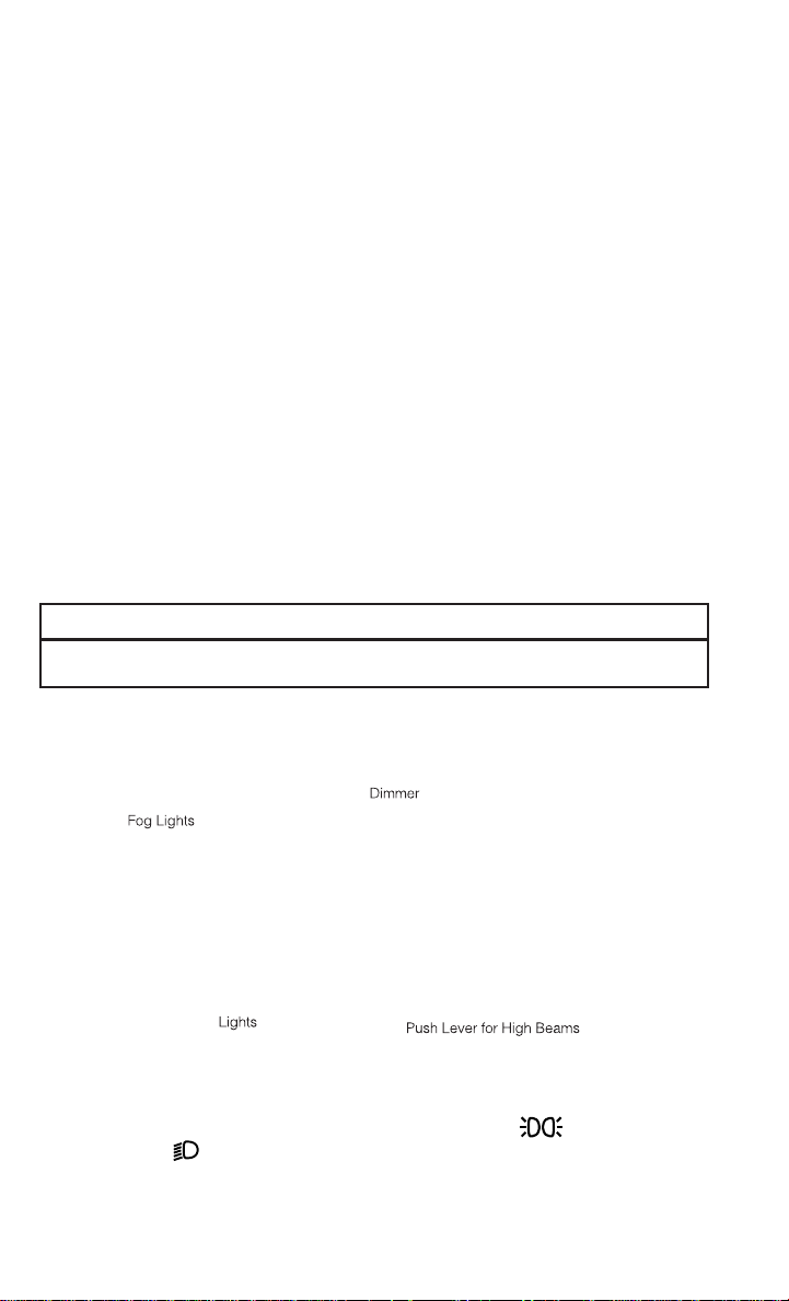
• Rotatethe end of the lever to the first detent for parking lights , the second detent
for headlights
• When set to AUTO, the system automatically turns the headlights on or off based on
ambient light levels.
, and the third detent for AUTO.
20
Page 23

OPERATING YOUR VEHICLE
Instrument Panel Dimmer
• Rotate the center portion of the lever to the extreme bottom position to fully dim the
instrument panel lights and prevent the interior lights from illuminating when a door is
opened.
• Rotate the center portion of the lever up to increase the brightness of the instrument
panel lights when the parking lights or headlights are on.
• Rotate the center portion of the lever upward to the next detent position to brighten the
odometer and radio controls when the parking lights or headlights are on.
• Rotate the center portion of the lever upward to the last detent to turn on the interior
lighting.
Flash To Pass
• Pull the lever toward you to activate the high beams. The high beams will remain on until
the lever is released.
High Beam Operation
• Push the lever forward to activate the high beams.
NOTE:
For safe driving, turn off the high beams when oncoming traffic is present to prevent
headlight glare and as a courtesy to other motorists.
Front Fog Lights
• Thefrontfoglight switch is on the multifunction lever.Toactivatethe front fog lights, turn
on the parking lights or the low beam headlights and pull out the end of the multifunction
lever.
Turn Signals/Lane Change Assist
• Tap the lever up or down once and the turn signal (right or left) will flash three times and
automatically turn off.
21
Page 24

OPERATING YOUR VEHICLE
WIPER/WASHER LEVER
Front Wipers
Intermittent, Low And High Operation
• Rotatethe end of thelever to the first detent position forone of five intermittent settings,
the second detent for low wiper operation and the third detent for high wiper operation.
Mist
• Pull down on the lever and release when a single wipe is desired.
NOTE:
The mist feature does not activate the washer pump; therefore, no washer fluid will be
sprayed on the windshield. The wash function must be activated in order to spray the
windshield with washer fluid.
Washer Operation
• Pull the lever toward you and hold for as long as spray is desired.
22
Page 25

OPERATING YOUR VEHICLE
SPEED CONTROL
• The Speed Control switches are located on the steering wheel.
Cruise ON/OFF
• Push the ON/OFF button to activate the
Speed Control.
• CRUISE
ment cluster to indicate the Speed Control is on.
• Push the ON/OFF button a second time to
turn the system off.
SET
• With the Speed Control on, push and release the SET – button to set a desired
speed.
Accel/Decel
To Increase Speed
• When the Electronic Speed Control is set,
you can increase speed by pushing the
RES + button.
• The speed increment shown is dependant on the speed of U.S. (mph) or Metric (km/h)
units:
U.S. Speed (mph)
• Pressing the RES + button once will result in a 1 mph increase in set speed. Each
subsequent tap of the button results in an increase of 1 mph.
• If the button is continually pressed, the set speed will continue to increase until the
button is released, then the new set speed will be established.
Metric Speed (km/h)
• Pressing the RES + button once will result in a 2 km/h increase in set speed. Each
subsequent tap of the button results in an increase of 2 km/h.
• If the button is continually pressed, the set speed will continue to increase until the
button is released, then the new set speed will be established.
will appear on the instru-
1 — Push On/Off
2 — Push Resume/Accel
3 — Push Set/Decel
4 — Push Cancel
23
Page 26

OPERATING YOUR VEHICLE
To Decrease Speed
• When the Electronic Speed Control is set, you can decrease speed by pushing the SET button.
• The speed decrement shown is dependant on the speed of U.S. (mph) or Metric (km/h)
units:
U.S. Speed (mph)
• Pressing the SET - button once will result in a 1 mph decrease in set speed. Each
subsequent tap of the button results in a decrease of 1 mph.
• If the button is continually pressed, the set speed will continue to decrease until the
button is released, then the new set speed will be established.
Metric Speed (km/h)
• Pressing the SET - button once will result in a 2 km/h decrease in set speed. Each
subsequent tap of the button results in a decrease of 2 km/h.
• If the button is continually pressed, the set speed will continue to decrease until the
button is released, then the new set speed will be established.
Resume
• To resume a previously selected set speed in memory, push the RES + button and
release.
Cancel
• Push the CANCEL button, or apply the brakes to cancel the set speed and maintain the
set speed memory.
• Push the ON/OFF button to turn the system off and erase the set speed memory.
WARNING!
• Leaving the Electronic Speed Control system on when not in use is dangerous. You
could accidentally set the system or cause it to go faster than you want. You could
lose control and have a collision. Always leave the Electronic Speed Control system
off when you are not using it.
• Electronic Speed Control can be dangerous where the system cannot maintain a
constant speed. Your vehicle could go too fast for the conditions, and you could lose
control. A collision could be the result. Do not use Electronic Speed Control in heavy
traffic or on roads that are winding, icy, snow-covered or slippery.
24
Page 27

OPERATING YOUR VEHICLE
MANUAL CLIMATE CONTROLS
Air Recirculation
• Use Recirculation for maximum A/C operation.
• For window defogging, turn the Recirculation button off.
• Recirculation is allowed in floor and defrost/floor (mix modes) for approximately five
minutes.
Heated Mirrors
• The mirrors are heatedto melt frostor ice. This feature is activated whenever you turn on
the rear window defroster.
25
Page 28

OPERATING YOUR VEHICLE
AUTOMATIC TEMPERATURE CONTROLS (ATC)
Automatic Operation
• Turn the Mode and Blower Controls to the AUTO position.
• Select the desired temperature by rotating the Temperature Control.
• The system will maintain the set temperature automatically.
Air Conditioning (A/C)
• If the air conditioning button is pressed while in AUTO mode, the system will exit AUTO
mode and stay in A/C. The mode and blower will go to the previous user setting.
Air Recirculation
• Use Recirculation for maximum A/C operation.
• For window defogging, turn the Recirculation button off.
• If the Recirculation button is pressed while in the AUTO mode, the indicator light may
flash three times to indicate the cabin air is being controlled automatically.
Heated Mirrors
• The mirrors are heatedto melt frostor ice. This feature is activated whenever you turn on
the rear window defroster.
26
Page 29

OPERATING YOUR VEHICLE
POWER SUNROOF
• The power sunroof switch is located on
the overhead console.
Opening Sunroof
Express Open
• Press the switch rearward and release it
within one-half second. The sunroof will
fully open and stop automatically.
Manual Open
• Press and hold the switch rearward to
open the sunroof. Any release of the
switch will stop the movement, and the
sunroof will remain in a partially open position until the switch is pressed again.
Venting Sunroof
• Pressand release the button and the sunroof will open to the vent position. This is
called “Express Vent” and will occur regardless of sunroof position. During Express Vent operation, any movement of the switch will stop the sunroof.
1 — Opening Sunroof
2 — Venting Sunroof
3 — Closing Sunroof
Closing Sunroof
Express Closing
• Press the switch forward and release it within one-half second. The sunroof will fully
close automatically from any position.
Manual Closing
• Pressand hold the switch forward to close the sunroof. Any releaseof the switch will stop
the movement, and the sunroof will remain in a partially closed position until the switch
is pressed again.
Pinch Protection Feature
• Thisfeaturewill detect an obstructionin the opening ofthe sunroof during ExpressClose
operation. If an obstruction in the path of the sunroof is detected, the sunroof will
automatically retract. Remove the obstruction if this occurs. Next, press the switch
forward and release to Express Close.
NOTE:
If three consecutive sunroof close attempts result in Pinch Protect reversals, the fourth
close attempt will be a Manual Close movement with Pinch Protect disabled.
27
Page 30

OPERATING YOUR VEHICLE
WARNING!
• Do notlet children play withthe sunroof.Neverleave children unattended in a vehicle,
or with access to an unlocked vehicle. Do not leave the Key Fob in or near the vehicle,
and do not leave the ignition of a vehicle equipped with Keyless Enter-N-Go™ in the
ACC or ON/RUN position. Occupants, particularly unattended children, can become
entrapped by the power sunroof while operating the power sunroof switch. Such
entrapment may result in serious injury or death.
• In a collision, there is a greater risk of being thrown from a vehicle with an open
sunroof. You could also be severely injured or killed. Always fasten your seat belt
properly and make sure all passengers are properly secured.
• Do not allow small children to operate the sunroof. Never allow your fingers, other
body parts, or any object to project through the sunroof opening. Injury may result.
28
Page 31

OPERATING YOUR VEHICLE
WIND BUFFETING
• Wind buffeting can be described as a helicopter-type percussion sound. If buffeting
occurs with the rear windows open, adjust the front and rear windows together.
• If buffeting occurs with the sunroof open, adjust the sunroof opening, or adjust any
window. This will minimize buffeting.
29
Page 32

ELECTRONICS
YOUR VEHICLE'S SOUND SYSTEM
1. Uconnect® Voice Command Button pg. 65
2. Uconnect® Phone Button pg. 62
3. Steering Wheel Audio Controls (Left) pg. 61
4. Steering Wheel Audio Controls (Right) pg. 61
30
Page 33

ELECTRONICS
5. USB port pg. 41
6. Audio Jack pg. 41
7. Power Outlet pg. 73
8. USB Port pg. 50
31
Page 34
ELECTRONICS
Uconnect® 130
NOTE:
• Your radio has many features that add to the comfort and convenience for you and your
passengers.
• Some of these radio features should not be used when driving because they take your
eyes from the road or your attention from driving.
Clock Setting
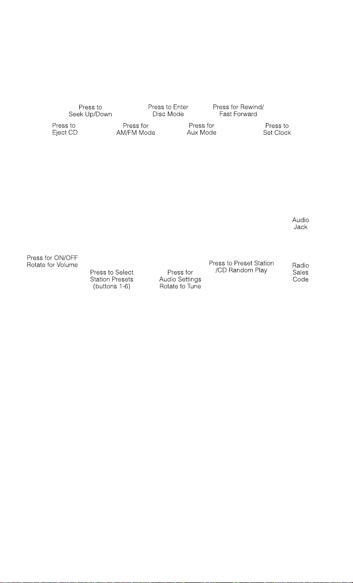
1. Press and hold the TIME button until the hours blink.
2. Turn the TUNE/SCROLL control knob to set the hours.
3. Press the TUNE/SCROLL control knob until the minutes begin to blink.
4. Turn the TUNE/SCROLL control knob to set the minutes.
5. Press the TUNE/SCROLL control knob to save the changes.
6. Press any button/knob or wait five seconds to exit.
32
Page 35

ELECTRONICS
Equalizer, Balance And Fade
1. Press the TUNE/SCROLL control knob and “BASS” will display.
2. Rotate the TUNE/SCROLL control knob to select the desired setting.
3. Continue pressing the TUNE/SCROLL control knob to display and set “MID RANGE,”
“TREBLE,” “BALANCE” and “FADE.”
Radio Operation
Seek Up/Down Buttons
• Press to seek through radio stations in AM or FM bands.
• Hold either button to bypass stations without stopping.
Store Radio Presets
• Pressthe SET/RNDor SET (depending on the radio)button once and SET1 will show inthe
display. Then select a preset button (1–6).
• A second station may be added to each push button. Press the SET/RND or SET
(depending on the radio) button twice and SET 2 will show in the display. Then select a
preset button (1–6).
CD/DISC Operation
Seek Up/Down Buttons
• Press to seek through CD tracks.
• Hold either button to bypass tracks without stopping.
SET/RND Or RND (Depending On Radio) Button (Random Play)
• Press this button while the CD is playing to activate Random Play.
• This feature plays the selections on the CD in random order to provide an interesting
change of pace.
Audio Jack Operation
• The AUX/Audio Jack provides a means to connect a portable audio device, such as an
MP3 player or an iPod®, to the vehicle’s sound system. This requires the use of a 3.5 mm
stereo audio patch cable.
• Pressing the AUX button will change the mode to auxiliary device if the Audio Jack is
connected, allowing the music from your portable device to play through the vehicle's
speakers.
The functions of theportable device are controlledusingthe device buttons, notthe buttons
•
on the radio. However, the volume may be controlled using the radio or portable device.
33
Page 36
ELECTRONICS
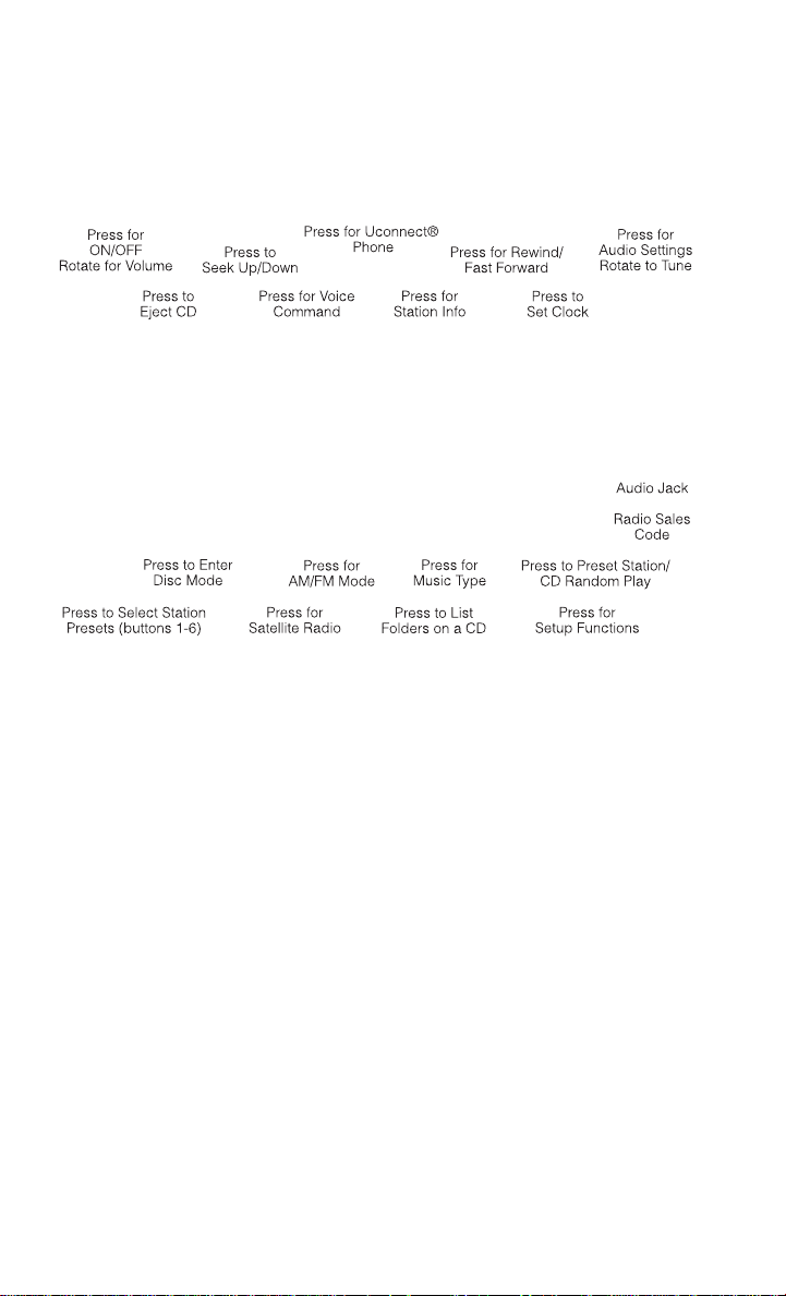
Uconnect® 130 WITH SiriusXM SATELLITE RADIO
NOTE:
• Your radio may not be equipped with the Uconnect® Voice Command and Uconnect®
Phone features. Todetermine if yourradio has these features, press the VoiceCommand
button on the radio.You will hear a voice prompt if youhave the feature, or seea message
on the radio stating “Uconnect Phone not available” if you do not.
• Your radio has many features that add to the comfort and convenience of you and your
passengers. Some of these radio featuresshould not be used when driving because they
take your eyes from the road or your attention from driving.
Clock Setting
1. Press and hold the TIME button until the hours blink.
2. Turn the TUNE/SCROLL control knob to set the hours.
3. Press the TUNE/SCROLL control knob until the minutes begin to blink.
4. Turn the TUNE/SCROLL control knob to set the minutes.
5. Press the TUNE/SCROLL control knob to save the changes.
6. Press any button/knob or wait five seconds to exit.
34
Page 37

ELECTRONICS
Equalizer, Balance And Fade
1. Press the TUNE/SCROLL control knob and “BASS” will display.
2. Rotate the TUNE/SCROLL control knob to select the desired setting.
3. Continue pressing the TUNE/SCROLL control knob to display and set “MID RANGE,”
“TREBLE,” “BALANCE” and “FADE.”
Radio Operation
Seek Up/Down Buttons
• Press to seek through radio stations in AM, FM, or SAT bands.
• Hold either button to bypass stations without stopping.
Store Radio Presets
• Pressthe SET/RNDor SET (depending on the radio)button once and SET1 will show inthe
display. Then select a preset button (1–6).
• A second station may be added to each push button. Press the SET/RND or SET
(depending on the radio) button twice and SET 2 will show in the display. Then select a
preset button (1–6).
Music Type
NOTE:
The Music Type function only operates when in FM mode.
• Press the MUSIC TYPE button to activate this mode. Press the MUSIC TYPE button again
or turn the TUNE/SCROLL control knob to select the desired music type (Adult Hits,
Country, Jazz, Oldies, Rock, etc.).
• When a music type is chosen and the Music type is displayed, press either SEEK button
and the radio will only search for stations with the selected music type.
SETUP Button
• Pressing the SETUP button allows you to select between items that are available in that
particular mode.
• Turn the TUNE/SCROLL control knob to scroll through the entries. Push the AUDIO/
SELECT button to select an entry and make changes.
35
Page 38

ELECTRONICS
SiriusXM Satellite Radio
• SiriusXM services require subscriptions, sold separately after the 12-month trial included with the new vehicle purchase. If you decide to continue your service at the end
of your trial subscription, the plan you choose will automatically renew and bill at
then-current rates until you call SiriusXM at 1-866-635-2349 to cancel. See SiriusXM
Customer Agreement for complete terms at http://www.siriusxm.com. All fees and
programming subject to change.Our satellite service is available only to those at least18
and older in the 48 contiguous USA and D.C. Our Sirius satellite service is also available
in PR (with coverage limitations). Our Internet radio service is available throughout our
satellite service area and in AK and HI. © 2013 Sirius XM Radio Inc. Sirius, XM and all
related marks and logos are trademarks of Sirius XM Radio Inc.
• SiriusXM Satellite Radio gives you over 130 channels, including 100% commercial-free
music from nearly every genre, plus allyour favorite sports, news, talk and entertainment
channels–all with crystal clear, coast-to-coast coverage, all in one place and all at your
fingertips.
• To access SiriusXM Satellite Radio, press the SAT hard-key.
CD/DISC Operation
Seek Up/Down Buttons
• Press to seek through CD tracks.
• Hold either button to bypass tracks without stopping.
SET/RND or RND (Depending On Radio) Button (Random Play)
• Press this button while the CD is playing to activate Random Play.
• This feature plays the selections on the CD in random order to provide an interesting
change of pace.
LIST Button
• Press the LIST button to bring up a list of all folders on the CD. Scroll up or down the list
by turning the TUNE/SCROLL control knob.
• To select a folder from the list, press the TUNE/SCROLL control knob and the radio will
begin playing the files contained in that folder.
Audio Jack Operation
• The AUX/Audio Jack provides a means to connect a portable audio device, such as an
MP3 player or an iPod®, to the vehicle’s sound system. This requires the use of a 3.5 mm
stereo audio patch cable.
• Pressing the AUX button will change the mode to auxiliary device if the Audio Jack is
connected, allowing the music from your portable device to play through the vehicle's
speakers.
• The functions of the portable device are controlled using the device buttons, not the
buttons on the radio. However, the volume may be controlled using the radio or portable
device.
36
Page 39
ELECTRONICS
Uconnect® 430/430N
NOTE:
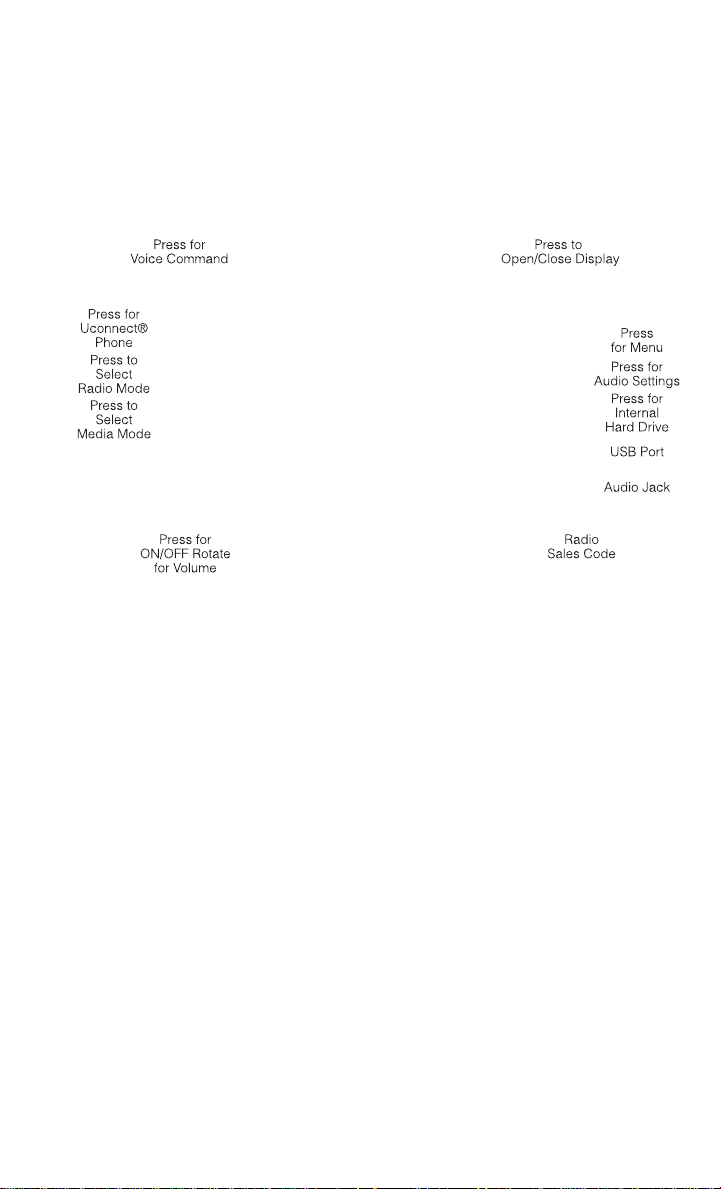
• Your radio may not be equipped with the Uconnect® Voice Command and Uconnect®
Phone features. Todetermine if yourradio has these features, press the VoiceCommand
button on the radio.You will hear avoice prompt if youhavethe feature, or see a message
on the radio stating “Uconnect Phone not available” if you do not.
• Your radio has many features that add to the comfort and convenience of you and your
passengers. Some of these radio featuresshould not be used when driving because they
take your eyes from the road or your attention from driving.
Clock Setting
1. Turn the radio on, then touch the screen where the time is displayed.
2. Touch the “User Clock” soft-key (Navigation radio only).
3. To adjust the hours, touch either the “Hour Forward” or “Hour Backward” soft-key.
4. Toadjust the minutes, touch either the “Minute Forward” or “Minute Backward” soft-key.
5. To save the new time setting, touch the screen where the word “Save” is displayed.
37
Page 40

ELECTRONICS
Menu
• Press the MENU hard-key to access the System Setup menu and the My Files menu.
• Press the MENU hard-key in an active mode (SAT, CD, AUX, etc.) to change mode specific
settings.
Equalizer, Balance And Fade
Audio Control Menu
• Press the “AUDIO” hard-key on the right
side of the radio.
• Use either the arrow soft-keys or the
cross-hair on the screen to change Balance and Fade. The “CENTER” soft-key
resets the settings.
• Touch the “Equalizer” soft-key and use
either the arrow soft-keysor the sliders on
the screen to adjust BASS, MID, and/or
TREBLE.
Display Settings
• Press the “MENU” hard-key and touch the
“Display Settings” soft-key to access the
Display Settings menu.
• Select the “Daytime Colors” soft-key to
switch to manual daytime mode and to
adjust the brightness of the display using
daytime colors.
• Select the “Nighttime Colors” soft-key to
switch to manual nighttime mode and to
adjust the brightness of the display using nighttime colors.
• Select the “Auto Color Mode” soft-key to switch to automatic daytime/nighttime mode
and to control the brightness of the display using the dimmer switch of the vehicle.
• Touch the “EXIT” soft-key to save your settings.
38
Page 41

ELECTRONICS
Radio Operation
• To access Radio Mode, touch the “RADIO” hard-key on the left side of the faceplate, then
touch the “AM,” “FM” or “SAT” soft-key at the top of the screen to select the band.
Seek Up/Seek Down
• Press the “Seek Up” or “Seek Down” soft-keys to seek through radio stations in AM, FM,
or SAT bands. Hold either Seek to bypass stations without stopping.
Store Radio Presets
• Select the radio band by touching either the “AM,” “FM,” or “SAT” soft-key.
• Find the station to store by either pressing the “Seek Up” or “Seek Down” soft-keys,
touching the “SCAN” soft-key, or by using the “DIRECT TUNE” soft-key.
• Once the station is found, touch and hold one of the “PRESET” soft-keys in the list to the
right, until the preset key flashes and the station text on the soft-key changes.
NOTE:
If the Presets are not visible on the right side of the screen, press the “Presets” soft-key.
39
Page 42
ELECTRONICS
CD/DVD Disc Operation
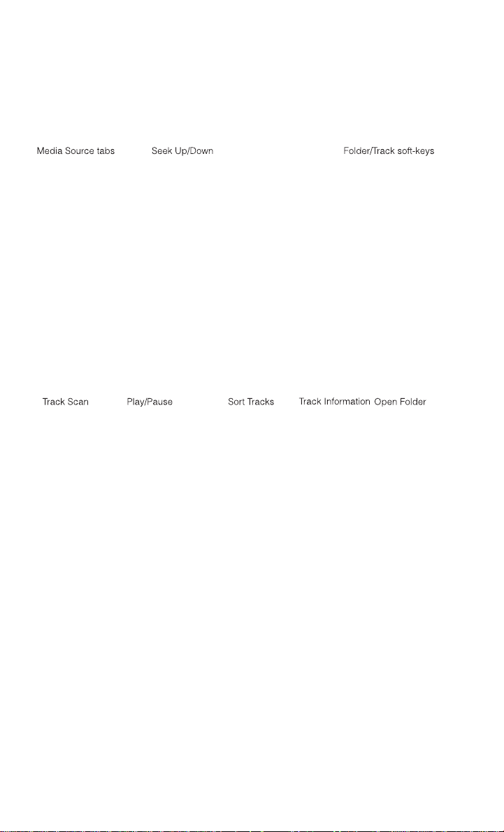
• Press the “MEDIA” hard key to display the media source tabs at the top of the screen.
Select the source by touching the “HDD,” “DISC,” or “AUX” media source soft-key tab.
NOTE:
Your Touchscreen Radio will usually automatically switch to the appropriate mode when
something is first connected or inserted into the system.
Insert a CD/DVD Disc
• To insert a disc, press the “LOAD” hard-key.
• With the printed side upwards, insert the disc into the disc slot of the radio. The radio
pulls the disc in automatically and closes the flip screen. The radio selects the appropriate mode after the disc is recognized, and starts playing the first track. The display
shows “Reading...” during this process.
Seek Up/Seek Down
• Press the “Seek Up” or “Seek Down” soft-keys to seek through tracks in Disc Mode.
Holding the “Seek Up” soft-key will fast forward through the track until the beginning of
the track is reached; if still held it will fast-forward through the next sequential track(s) (if
random play mode is not active) until released. Holding the “Seek Down” soft-key will
fast-reversethrough the track until thebeginning of the trackis reached; if still heldit will
fast-reversethrough the next sequential track(s) (if random play mode is not active) until
released.
40
Page 43

ELECTRONICS
Audio Jack Operation
• The AUX/Audio Jack provides a means to connect a portable audio device, such as an
MP3 player or an iPod®, to the vehicle’s sound system. This requires the use of a 3.5 mm
stereo audio patch cable.
• Pressthe MEDIA hard-key then the “AUX”soft-keyto change the mode toauxiliary device
if the Audio Jack is connected, allowing the music from your portable device to play
through the vehicle's speakers.
• The functions of the portable device are controlled using the device itself, not the
buttons on the radio. However, the volume may be controlled using the radio or portable
device.
Hard Disk Drive (HDD) Operation
• The Hard Disk Drive (HDD) mode gives you access to the audio files on the internal hard
disk drive. Itfunctions similar to a CD player, with the exception that the internal HDD can
hold more tracks.
• It is also possible to import display pictures to the internal hard disk drive. The pictures
can be displayed on the right half of the radio screen.
• Beforeusing the HDD mode, you will need to copy songs and pictures to the internal hard
drive. Songs and pictures can be added to the harddrive by using a CD or USB device (e.g.
thumb drive or memory stick).
NOTE:
• HDD supports only .jpg/JPEG formats for photos.
• WMA/MP3 Files and Selective Songs from a CD can also be added to the HDD. See the
Uconnect® 430/430N User's Manual for more information.
Copying Music From CD
• Press the “LOAD” hard-key.
• Insert a disc, then press the “MY FILES” hard-key and then select “MY MUSIC” soft-key.
• Touch the “Add Music Files to HDD” soft-key, then touch the “Disc” soft-key in the next
screen to start the process.
NOTE:
• You might need to select the folder or title
depending on the CD, then press “DONE”
to start the copy process.
• The copy progress is shown in the lower
left corner of the screen.
41
Page 44

ELECTRONICS
Copying Music From USB
• TheUSB port on the radio faceplate allows you tocopy files to your hard drive. Toaccess,
lift up the cover.
• Insert a USB device (e.g. thumb drive or memory stick), then select the “MY MUSIC”
soft-key.
• Touch the “Add Music Files to HDD” soft-key, then touch the “Front USB” soft-key in the
next screen.
• Select the folders or titles you would like
to copy, then touch the “SAVE”soft-key to
start the copy process. To copy all of the
titles touch the "ALL" soft-key, then press
the "SAVE" soft-key.
NOTE:
The copy progress is shown in the lower left
corner of the screen.
Copying Pictures To The HDD
• Insert either a CD or a USB device containing your pictures in JPEG format.
• Press the “MY FILES” hard-key.
• Touch the “My Pictures” soft-key to get an overview of the currently stored images, then
touch the “Add” soft-key.
• Touch the “Disc” or “USB” soft-key, then select the folders or pictures you wish to copy to
the HDD. Use the “PAGE” soft-keys to page through the list of pictures.
• Touch the desired pictures or press the “All” soft-key for all pictures. Confirm your
selections by touching the “SAVE” soft-key.
NOTE:
The copy progress is shown in the lower left
corner of the screen.
Display A Picture On The Radio Screen
• Once the import is complete, the pictures
will then be available in the “MY PICTURES” screen.
• Press the “MY FILES” hard-key, then
touch the “My Pictures” soft-key. Touch the desired picture, touch the “Set as Picture
View” soft-key and then touch the “Exit” soft-key. Finally, press the “MENU” hard-key and
touch the “Picture View” soft-key to display the chosen picture on the radio screen.
NOTE:
• A check mark in the “My Pictures” screen indicates the currently used picture.
• You can also delete pictures by touching the “Delete” soft-key.
42
Page 45

ELECTRONICS
Playing Music From The HDD
• Press the “MEDIA” hard-key to display the media source tabs at the top of the screen.
Touch the “HDD” soft-key tab. Touch the desired track soft-key to play or touch the
“SEARCH/BROWSE” soft-key to search by artist, by album, by song, by genre, from a
folder, or from Favorites.
Cleaning Your Touchscreen Radio
• Do not spray any liquid or caustic chemicals directly on the screen. Use a clean and dry
micro fiber lens cleaning cloth to clean the touchscreen.
• If necessary, use a lint-free cloth dampened with a cleaning solution such as isopropyl
alcohol or an isopropyl alcohol and water solution ratio of 50:50. Always follow the
solvent manufacturer's precautions and directions.
Garmin® Navigation
• Uconnect® 430N integrates Garmin’s consumer-friendly navigation into your vehicle.
Garmin® Navigation includes a database with over six million points of interest.
• Touch the “NAV”soft-key in the upper right corner of the screen to access the Navigation
system.
Changing The Navigation Voice Prompt
Volume
1. Program a destination.
2. While traveling on your route, touch the
upper left area of the map screen where
your next turn is displayed.
3. The Navigation system will then repeat
the distance to your next turn.
4. While the Navigation system is speaking, use the ON/OFF VOLUME rotary knob to adjust
the volume to a comfortable level. Please note the volume setting for Navigation Voice
Prompt is different than the audio system.
NOTE:
For your own safety and the safety of others, it is not possible to use certain featureswhile
the vehicle is in motion.
43
Page 46

ELECTRONICS
Main Navigation Menu
Finding Points Of Interest
• From the main Navigation menu, touch the “Where To?” soft-key,then touch the “Points
of Interest” soft-key.
• Select a Category, then a subcategory, if
necessary.
• Select your destination and touch the
“Go” soft-key.
Finding A Place By Spelling The Name
• Fromthe Main Navigation Menu touch the
“Where To?” soft-key. Next, touch the
“Points of Interest” soft-key then touch
the “Spell Name” soft-key.
• Enter the name of your destination.
• Touch the “Done” soft-key.
• Select your destination and touch the “Go” soft-key.
Entering A Destination Address
• From the main Navigation menu touch the “Where To?” soft-key, then touch the “Address” soft-key.
• Follow the on-screen prompts to enter the address then touch the “Go” soft-key.
Setting Your Home Location
• From the main Navigation menu touch the "Tools" icon. Next select the "My Data" folder
icon. Then select "Set Home Location."
• You may enter your address directly, use your current location as your home address, or
choose from recently found locations.
Edit Home Location
• From the main Navigation menu touch the “Where To?” soft-key, then touch the "Tools"
icon. Next, touch the "My Data" folder.
• You may enter a new address directly, use your current location or choose from recently
found locations.
Go Home
• A Home location must be saved in the system. From the Main Navigation menu, touch
the “Where To?” soft-key, then touch the “Go Home” soft-key.
44
Page 47

ELECTRONICS
Following Your Route
•
Your route is marked with a magenta line on the map. If you depart from the original route,
your route is recalculated. A speed limit icon could appear as you travel on major roadways.
Adding A Via Point
• To add a stop between the current location and the end destination (Via Point) you must
be navigating a route.
• Touch the “back arrow” icon multiple times to return to the Main Navigation menu.
• Touch the “Where To?” soft-key, then search for the additional stop. Select the destination you wish to add from the given search results.
•
Touch the “Go” soft-key,thentouch "Add as a Via Point"soft-keyand press the "Done" soft-key.
Taking A Detour
• To take a detour you must be navigating a route.
•
Touch the “back arrow” icon soft-key multiple times to return to the Main Navigation menu.
• Touch the “Detour” soft-key.
NOTE:
If the route you are currently taking is the only reasonable option, the device might not
calculate a detour.
Acquiring Satellites
• The GPS Satellite strength bars indicate the strength of your satellite reception.
• Acquiringsatellite signals can takea few minutes. When at least one of the barsis green,
your device has acquired satellite signals.
• You may experience delays receiving satellite signals when in areas with an obstructed
view to the sky, such as garages, tunnels, or large cities with tall buildings.
45
Page 48
ELECTRONICS
Uconnect® 730N
NOTE:
Your radio has many features that add to the comfort and convenience of you and your
passengers. Some of these radio features should not be used when driving because they
take your eyes from the road or your attention from driving.
Clock Setting
1. Turn the radio on, then touch the screen where the time is displayed.
2. Touch the “User Clock” soft-key.
3. To adjust the hours, touch either the “Hour Forward” or “Hour Backward” soft-key.
4. Toadjust the minutes, touch either the “Minute Forward” or “Minute Backward” soft-key.
5. To save the new time setting, touch the screen where the word “Save” is displayed.
Menu
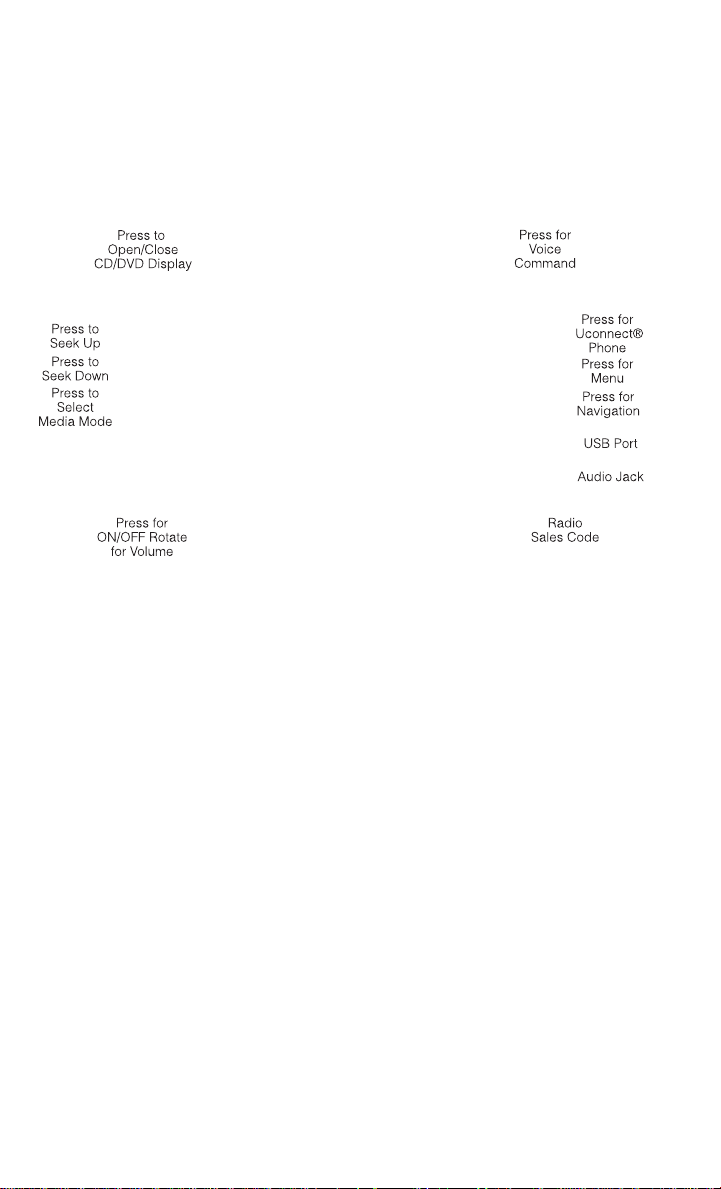
• Press the MENU hard-key to access the System Setup menu and the My Files menu.
• Press the MENU hard-key in an active mode (SAT, CD, AUX, etc.) to change mode specific
settings.
46
Page 49

ELECTRONICS
Equalizer, Balance And Fade
Audio Control Menu
• Pressthe MENU hard-key onthe right side
of the radio. Then press the “Audio Control” soft-key to get to the audio control
menu.
• Use either the arrow soft-keys or the
cross-hair on the screen to change Balance and Fade. The “Center” soft-key resets the settings.
• Touch the “Equalizer” soft-key and use
either the arrow soft-keys or the sliders on the screen to adjust BASS, MID, and/or
TREBLE.
Display Settings
• Press the MENU hard-key and touch the
“Display Settings” soft-key to access the
Display Settings menu.
• Select the “Daytime Colors” soft-key to
switch to manual daytime mode and to
adjust the brightness of the display using
daytime colors.
• Select the “Nighttime Colors” soft-key to
switch to manual nighttime mode and to
adjust the brightness of the display using nighttime colors.
• Select the “Auto Color Mode” soft-key to switch to automatic daytime/nighttime mode
and to control the brightness of the display using the dimmer switch of the vehicle.
• Touch the “EXIT” soft-key to save your settings.
47
Page 50
ELECTRONICS
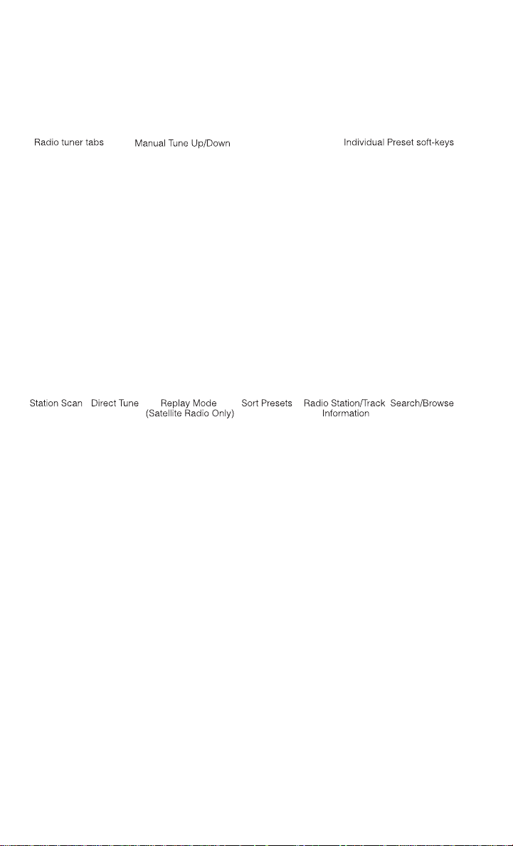
Radio Operation
• To access Radio Mode, touch the RADIO/MEDIA hard-keyon the left side of the faceplate
repeatedly until AM/FM/SATappears at the top of the screen, then touch the “AM,” “FM”
or “SAT” soft-key to select the band.
Seek Up/Seek Down
• Press the SEEK UP or SEEK DOWN hard-keys to seek through radio stations in AM, FM, or
SAT bands. Hold either Seek to bypass stations without stopping.
Store Radio Presets
• Select the radio band by touching either the “AM,” “FM” or “SAT” soft-key.
• Find the station to store by either pressing the SEEK UP or SEEK DOWN hard-keys,
touching the “SCAN” soft-key, or by using the “DIRECT TUNE” soft-key.
• Oncethe station is found, touch and hold one of the“PRESETS” soft-keys in the listto the
right, until you hear a confirmation beep.
NOTE:
If the Presets are not visible on the right side of the screen, press the “PRESETS” soft-key.
48
Page 51
ELECTRONICS
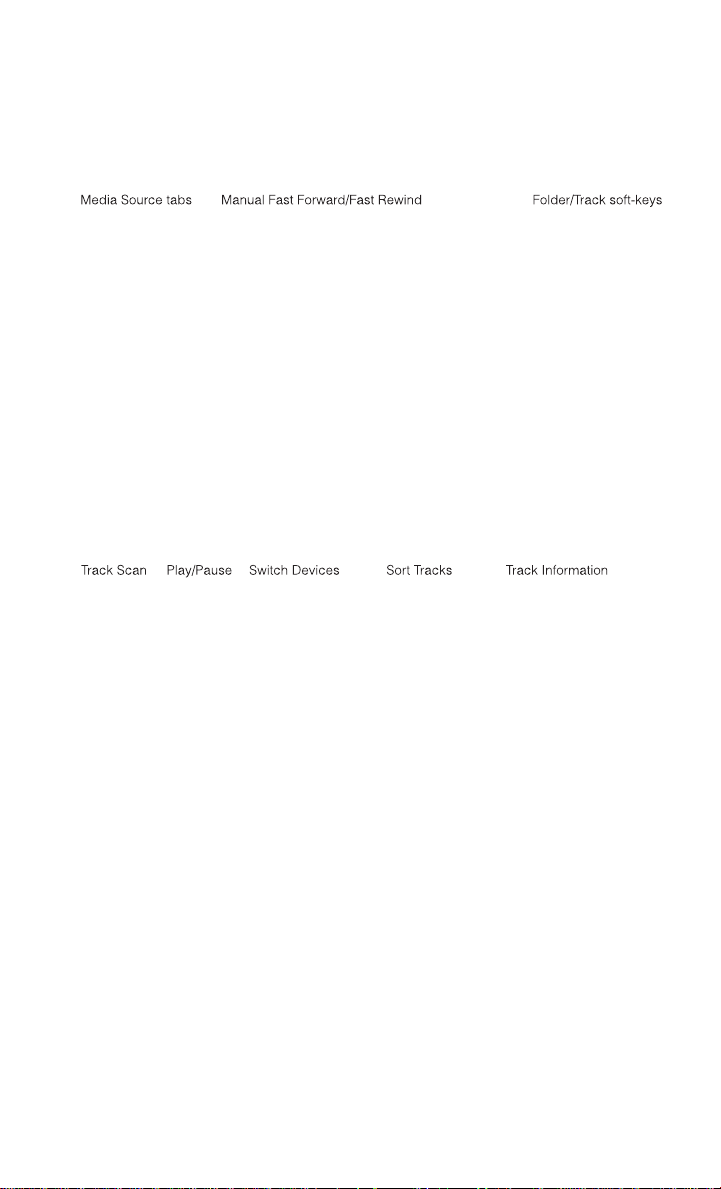
CD/DVD Disc Operation
• Press the RADIO/MEDIA hard-key until the media source tabs are displayed at the top of
the screen. Select the source by touching the “HDD,” “DISC” or “AUX” media source
soft-key tab.
NOTE:
Your Touchscreen Radio will usually automatically switch to the appropriate mode when
something is first connected or inserted into the system.
Insert A CD/DVD Disc
• To insert a disc, press the OPEN/CLOSE hard-key.
• With the printed side upwards, insert the disc into the disc slot of the radio. The radio
pulls the disc in automatically and closes the flip screen. The radio selects the appropriate mode after the disc is recognized, and starts playing the first track. The display
shows “Reading...” during this process.
Seek Up/Seek Down
• Press the SEEK UP or SEEK DOWN hard-keys to seek through tracks in Disc Mode. Hold
either SEEK to bypass tracks without stopping.
49
Page 52

ELECTRONICS
Audio Jack Operation
• The AUX/Audio Jack provides a means to connect a portable audio device, such as an
MP3 player or an iPod®, to the vehicle’s sound system. This requires the use of a 3.5 mm
stereo audio patch cable.
• Press the RADIO/MEDIA hard-key, then the “AUX” soft-key to change the mode to
auxiliary device if the Audio Jack is connected, allowing the music from your portable
device to play through the vehicle's speakers.
• The functions of the portable device are controlled using the device itself, not the
buttons on the radio. The volume may be controlled using the radio or portable device.
Hard Disk Drive (HDD) Operation
• The Hard Disk Drive (HDD) mode gives you access to the audio files on the internal hard
disk drive. Itfunctions similar to a CD player, with the exception that the internal HDD can
hold more tracks.
• It is also possible to import display pictures to the internal hard disk drive. The pictures
can be displayed on the right half of the radio screen.
• Beforeusing the HDDmode, you will need to copy songs and pictures to the internal hard
drive. Songs and pictures can be added to the harddrive by using a CD or USB device (e.g.
thumb drive or memory stick).
NOTE:
• HDD supports only .jpg/JPEG formats for photos.
• WMA/MP3 Files and Selective Songs from a CD can also be added to the HDD. See the
Uconnect® 730N Supplement Manual for more information.
Copying Music From CD
• Press the OPEN/CLOSE hard-key.
• Insert a disc, then press the MENU hard-key.
• Touch the “MY FILES” soft-key, then select “MY MUSIC.”
50
Page 53

ELECTRONICS
• Touch the “Add Music Files to HDD” soft-key, then touch the “From Disc” soft-key in the
next screen to start the process.
NOTE:
• You might need to select the folder or title
depending on the CD, then press “Done”
to start the copy process.
• The copy progress is shown in the lower
left corner of the screen.
Copying Music From USB
• TheUSB port on the radio faceplate allows you tocopy files to your hard drive. Toaccess,
lift up on the cover.
• Insert a USB device (e.g. thumb drive or memory stick), then select “MY FILES.”
• Touch the “MY MUSIC” soft-key, then touch the “Add Music Files” to HDD soft-key.
• Touch the“From USB” soft-key,then select the folders or titlesyouwould like to copy, and
then touch the “SAVE” soft-key to start the copy process.
NOTE:
The copy progress is shown in the lower left
corner of the screen.
51
Page 54

ELECTRONICS
Copying Pictures To The HDD
• Insert either a CD or a USB device containing your pictures in JPEG format.
• Press the MENU hard-key to access the Settings Menu, then touch the “My Files”
soft-key.
• Touch the “My Pictures” soft-key to get an overview of the currently stored images, then
touch the “Add” soft-key.
• Touch the “From Disc” or “From USB”
soft-key, then select the folders or pictures you wish to copy tothe HDD. Use the
“PAGE” soft-keys to page through the list
of pictures.
• Touch the desired pictures or press the
“All” soft-key for all pictures. Confirm your
selections by touching the “SAVE”
soft-key.
NOTE:
The copy progress is shown in the lower left corner of the screen.
Display A Picture On The Radio Screen
• Once the import is complete, the pictures will then be available in the “MY PICTURES”
screen.
• Pressthe MENU hard-keyto access the Settings Menu. Touch the “My Files” soft-key and
then touch the “My Pictures” soft-key. Touch the desired picture, touch the “Set as
Picture View” soft-key and then touch the “Exit” soft-key. Lastly press the MENU hardkey and touch the “Picture View” soft-key to display the chosen picture on the radio
screen.
NOTE:
• A check mark in the My Pictures screen indicates the currently used picture.
• You can also delete pictures by touching the “Delete” soft-key.
52
Page 55

ELECTRONICS
Playing Music From The HDD
• Press the RADIO/MEDIA hard-key until the media source tabs are displayed at the top of
the screen. Touch the “HDD” soft-key tab. Touch the desired track soft-key to play or
touch the “SEARCH/BROWSE” soft-key to search by artist, by album, by song, by genre,
from a folder, or from Favorites.
Cleaning Your Touchscreen Radio
• Do not spray any liquid or caustic chemicals directly on the screen. Use a clean and dry
micro fiber lens cleaning cloth to clean the touchscreen.
• If necessary, use a lint-free cloth dampened with a cleaning solution such as isopropyl
alcohol or an isopropyl alcohol and water solution ratio of 50:50. Always follow the
solvent manufacturer's precautions and directions.
Navigation
• Your navigation system receives GPS signals from up to 16 satellites to display the
position of your vehicle. Map and database information is supplied through a
hard disk drive.
• Touch the NAV hard-key on the radio face
plate to access the Navigation system
and the NAV – Main Menu.
Changing The Navigation Guidance Prompt Volume
1. From the Navigation Map screen, touch the MENU hard-key then touch the “NAV Settings” soft-key. Next select "Guidance Prompts."
Select and adjust the navigation guidance prompt volume using the left and right arrows.
2.
3. Touch the “SAMPLE VOL” soft-key to lis-
ten to the current volume setting.
53
Page 56
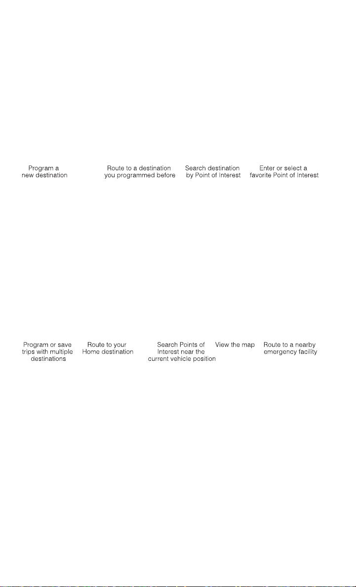
ELECTRONICS
4. Once satisfied with thevolume, touch the “SAVE” soft-key to save the settings. Touch the
“CANCEL” soft-key to exit the menu without saving the settings.
NOTE:
For your own safety and the safety of others, it is not possible to use certain featureswhile
the vehicle is in motion.
Main Navigation Menu
Finding Points Of Interest
• From the NAV main menu, touch the “Points of Interest” soft-key.
• Select a Category and then a subcategory, if necessary.
• Select your destination and touch “GO.”
Finding A Place By Entering The Street Address
NOTE:
Tip: Entering the city or zip code before entering the street name facilitates address entry.
If the State and/or Country displayed are incorrect, touch the corresponding soft-key to
make the correction.
• From the NAV main menu, touch “New Destination,” then touch “Street Address.”
• Once the Country and State are set and the Street Address screen is displayed, begin
spelling the street name in the speller. In the upper right corner the number of possible
roads decreases.
54
Page 57

ELECTRONICS
• Touch the “LIST” soft-key to display a list of possible street names. Select the correct
street name.
• Next input the number.
• In the Confirm Route screen the navigation radio displays the complete address, a map
of the destination area, and the current routing method for you to verify.
• Touch the “GO” soft-key to activate the route guidance.
Entering Your Home Location
• Press the NAV hard-key on the right side of the radio.
• From the Nav – Main Menu, touch “Guide Me Home” to enter your home address. If no
home address has been set, touch “YES” to access the Enter Home Address menu.
• Touch “Street Address” to enter your address. Touch the soft-key with your state’s name
and enter your street name into the speller.
• Once the street name has been input, touch “CONTINUE” to confirm. Enter the house
number into the next screen. If more than one city has this address, you will then need to
select your city from a list.
• Once the address is entered completely, the system shows a map of your home address
area. Touch “SAVE” to confirm the address. The system will then ask if you want to go
there. Touch the “Yes” or “No” soft-key.
Change Home Address
NOTE:
This procedure will allow you to change your HomeAddressif one has alreadybeen entered.
Entering the city or zip code before entering the street name facilitates address entry.
• Press the MENU hard-key, touch “My Files” and then touch “My Address Book.”
• Touch “Home”, then touch “Edit Contacts” and then “Change Address.”
• Touch the soft-key with your state’s name and enter your street name into the speller.
• Once the street name has been input, touch “CONTINUE” to confirm.
• Enter the house number into the next screen. If more than one city has this address, you
will then need to select your city from a list.
• Touch the “SAVE” soft-key to confirm the address.
Go Home
• From the NAV main menu, touch “Guide Me Home” when you want to route to your home
destination.
Where Am I Now?
• From the NAV main menu, touch “Where Am I Now?” The Where Am I Now? menu
displays location information for the current vehicle position.
• Touch the “NEARBY POI” soft-key to search for a local Point of Interest.
• Touch the “SAVE LOCATION” soft-key to save the current location in the Saved Locations
memory.
55
Page 58
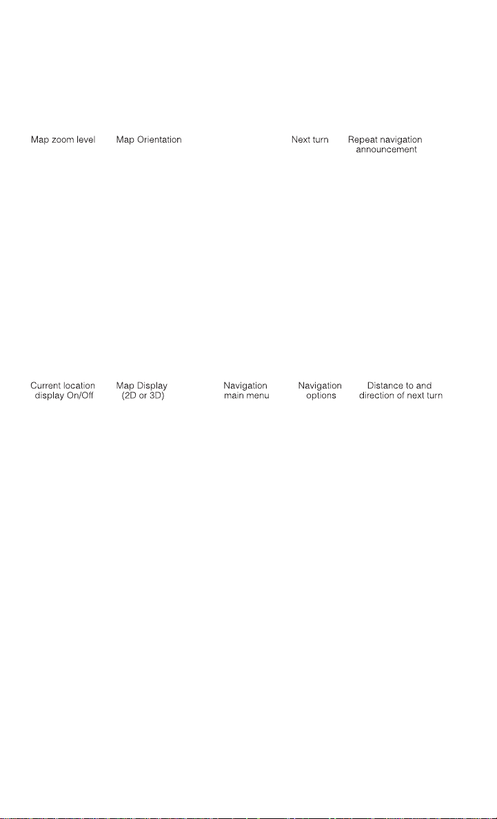
ELECTRONICS
Route Guidance
• After starting route guidance, the system calculates the route and announces: “Follow
the arrows on the display.” You will receive navigation recommendations by voice messages and screen displays.
Route Options
• After pressing the “OPTIONS” soft-key in the Route Guidance Menu, the following information is displayed:
• In the left half of the screen, the current position and the current routing method are
displayed.
• “ Take Detour” will allow you to calculate a different route.
• “Find Nearby POI” to search for a local POI.
• “Destination Info” displays destination information.
• “View Turn List” lists streets utilized for the current route.
• “Save Destination” to save the destination address.
• “Change Method” will allow you to change the routing method.
56
Page 59

ELECTRONICS
SiriusXM SATELLITE RADIO/TRAVEL LINK
• SiriusXM Travel Link requires a subscription, sold separately after the 1 year trial subscription included with your vehicle purchase.
• SiriusXM Travel Link is only available in the United States.
The following describes features that are available when in SiriusXM Satellite Radio mode.
•
• To access SiriusXM Satellite Radio, press the RADIO/MEDIA or RADIO hard-key, then
touch the “SAT” soft-key tab.
Info
• Touch the “i” soft-key to view detailed information about the current Sirius XM Satellite
channel.
SiriusXM Parental Controls
• SiriusXM offers the option to permanently block selected channels. Call 1-888-539-7474
and request the Family Package.
• Uconnect® 430/430N and 730N: Press the “MENU” hard-key while in SiriusXM Satellite
Radio Mode, then touch the “Channel Lock” to enable and/or disable desired channels.
The SEEK and SCAN function will then only display channels without Channel lock.
Search/Browse
• Touch the “magnifying glass” soft-key to search/browse the SiriusXM channel listing by
Favorites and Categories such as Song, Artist and Channel Name. The Search/Browse
also allows you to manage your Favorites.
57
Page 60

ELECTRONICS
SiriusXM Satellite Radio Favorites (SAT Favorites)
• You can save 50 favorite songs and 50 favorite artists.
Touch the “Add Favorite” soft-key to add
•
either the song or the artist of the currently
playing program to the SAT Favorites list.
The favorite star will appear in the upper
right corner, below the “SAT” soft-key.
• You will see a favorite star indicator in the upper right side of the screen below the “SAT”
soft-keyand a pop up will alert you that afavoritesong or artist iscurrently playing on one
of the SiriusXM satellite radio channels.
NOTE:
Refer to your Uconnect® 730N or 430/430N
Supplement Manual for more information.
Display SAT Favorites List
• Touch the “Search/Browse” soft-key andselect “Favorites” from the SATBrowse screen.
• Touch the desired favorites soft-key to
switch the SAT tuner to thecorresponding
channel.
• You may use the “LIST” soft-key to toggle
between:
• Favorite Songs
• Favorite Artists
• Currently playing favorites
58
Page 61

ELECTRONICS
Replay
• While you are in SAT mode, you can replay 44 minutes of the current SiriusXM channel
(when the channel is changed, this audio buffer is erased). Press the REPLAY button to
listen to the stored audio.
• You can touch the on-screen controls to
pause and rewind audio playback, touch
the SCAN button to preview each of the
tracks stored in the buffer, or select a
track from the list.
• The time displayed below the bar indicates how much time is present between
the current buffer play position and the
live broadcast.
Replay Option Option Description
Play/Pause Touch to pause content playback. Touch Pause/Play again to resume
Rewind/RW Rewinds the channel content in steps of five seconds. Touch and hold to
Fast Forward/FW Forwards the content, and works similarly to Rewind/RW. However, Fast
Replay Time Displays the amount of time in the uppercenterof the screen by which your
Live Resumes playback of live content at any time while replaying rewound
playback.
rewind continuously, then release to begin playing content at that point.
Forward/FW can only be used when content has been previously rewound.
content lags the live channel.
content.
59
Page 62

ELECTRONICS
SiriusXM Travel Link (Uconnect® 730N & Uconnect® 430N Only)
• SiriusXM Travel Link brings a wealth of useful information into your vehicle and right to
your fingertips.
• To access Travel Link, press the MENU hard-key, then the “Travel Link” soft-key.
1 – Favorites
2 – Forecast
3 – Ski Info
4 – Fuel Prices
5 – Movies
6 – Sports
NOTE:
• SiriusXM Travel Link requires a subscription, sold separately after the 1 year trial subscription included with your vehicle purchase.
• SiriusXM Travel Link is only available in the United States.
View and storeyour favorite location, theater and sport teams
for quick access.
View detailed weather conditions, forecasts and ski/
snowboarding conditions at resorts.
View ski and snowboarding conditions at ski resorts.
View detailed price information for fuel stations.
View information on movies that are playing at theaters.
View sports scores and upcoming events for all major sports.
60
Page 63

ELECTRONICS
STEERING WHEEL AUDIO CONTROLS
• The steering wheel audio controls are located on the rear surface of the steering
wheel.
Right Switch
• Pressthe switch up or down to increaseor
decrease the volume.
• Press the button in the center to change
modes AM/FM/CD/SAT.
Left Switch
• Press the switch up or down to search for the next listenable station or select the next or
previous CD track.
• Press the button in the center to select the next preset station (radio) or to change CDs if
equipped with a CD Changer.
iPod®/USB/MP3 CONTROL
• Thereare many waysto play musicfrom iPod®/MP3 playersor USB devices through your
vehicle's sound system.
• The remote USB port, located within the front storage area, allows you to plug an iPod®
into the vehicle's sound system.
NOTE:
If equipped with the Uconnect® 730N, the
USB port on the faceplate allows the same
functions as the remote USB port.
• Non-Touchscreen Radios: To hear audio
from devices connected to the USB port,
press the “AUX” button on the radio faceplate.
61
Page 64
ELECTRONICS
• Touchscreen Radios: To hear audio from devices connected to the USB port, press the
“MEDIA” hard-key, then touch the “AUX” or “iPod®” soft-key.
• When connected to this feature:
• The iPod® can be controlled using the
radio buttons to Play, Browse, and List
the iPod® or external devices contents.
• The iPod® battery charges when
plugged into the USB port (if supported
by the specific audio device).
• Compatible iPod® devices may also be
controllable using voice commands. Refer to the Owner's Manual on the DVD for
details.
NOTE:
The USB port supports certain Mini, Classic, Nano, Touch, and iPhone® devices. The USB
port also supports playing music from compatible external USB Mass Storage Class
memory devices. For supported audio file formats, refer to the USB Port section in the
Owner's Manual on the DVD. Refer to www.UconnectPhone.com website for a list of tested
iPod®s. Some iPod® software versions may not fully support the USB port features. Please
visit Apple’s website for iPod® software updates.
WARNING!
Do not plug in or remove the iPod® or external device while driving. Failure to follow this
warning could result in a collision.
Uconnect® PHONE
Uconnect® Phone
• To determine if your vehicle is equipped with Uconnect® Phone, press the “Uconnect®
Phone” button
will hear a voiceprompt.If not, you will seea message on theradio “Uconnect® Phone not
available.”
• The Uconnect® Phone is a voice-activated, hands-free, in-vehicle communications
system with Voice Command Capability (see Voice Command section).
NOTE:
To access the tutorial, press the “Uconnect® Phone” button
“tutorial.” Press any hard-key/buttonor touch the display (Touchscreen radio) to cancel the
“tutorial.”
• The Uconnect® Phone allows you to dial a phone number with your mobile phone using
simple voice commands.
• Refer to your vehicle Owner's Manual on the DVD for further details.
62
located on the radio faceplate. If your vehicle has this feature, you
. After the BEEP, say
Page 65

ELECTRONICS
NOTE:
The Uconnect® Phone requires a mobile phone equipped with the Bluetooth® Hands-Free
Profile, Version 1.0 or higher. For Uconnect® Customer Support: U.S. residents - visit
www.UconnectPhone.com or call 1–877–855–8400. Canadian residents - visit
www.UconnectPhone.com or call, 1-800-465–2001 (English) or 1-800-387-9983 (French).
This site will provide specific instructions based on the type of mobile phone being paired.
Phone Pairing
NOTE:
Pairing is a one - time initial setup before using the phone. Prior to star ting the pairing
procedure ensure all additional phones within the vehicle have their Bluetooth® disabled.
1. Press the “Phone”
2. Wait for the “ready” prompt and BEEP.
3. After the BEEP, say ”setup” or “Uconnect device setup.”
4. After the BEEP, say “device pairing.”
5. After the BEEP, say “pair a device.”
6. Follow the audible prompts.
• You will be asked to say a four-digit Personal Identification Number (PIN), which
you will later need to enter into your mobile phone. You can say any four-digit PIN.
You will not need to remember this PIN
after the initial pairing process.
• You will then be prompted to give the phone pairing a name (each phone paired should
have a unique name).
• Next you will beasked to give thisnew pairing a priority of 1 through 7 (up toseven phones
may be paired); 1 is the highest and 7 is the lowest priority. The system will only connect
to the highest priority phone that exists within the proximity of the vehicle.
• You will then need to start the pairing procedure on your cell phone. Follow the
Bluetooth® instructions in yourcell phone Owner's Manual to complete thephone pairing
setup.
button to begin.
63
Page 66

ELECTRONICS
Phonebook
Phonebook Download — Automatic Phonebook Transfer From Mobile Phone
• If equipped and specifically supported by your phone, Uconnect® Phone automatically
downloads names (text names) and number entries from your mobile phone’s phonebook. Specific Bluetooth® Phones with Phone Book Access Profile may support this
feature.AutomaticTransferis indicated by a greenarrowat the bottom of thescreen. See
www.UconnectPhone.com for supported phones.
• Automatic download and update, if supported, begins as soon as the Bluetooth®
wireless phone connection is made to the
Uconnect® Phone. For example, after you
start the vehicle.
NOTE:
The mobile phone may require authorization
prior to download.
• Amaximum of 1000 entries per phone will
be downloaded and updated every time a phone is connected to the Uconnect® Phone.
• Depending on the maximum number of entries downloaded, there may be a short delay
before the latest downloaded names can be used. Until then, if available, the previously
downloaded phonebook is available for use.
• Only the phonebook of the currently connected mobile phone is accessible.
• Only the mobile phone’s phonebook is downloaded. The SIM card phonebook is not part
of the Mobile phonebook.
• This downloaded phonebook cannot be edited or deleted on the Uconnect® Phone.
These can only be edited on the mobile phone. The changes are transferred and updated
to Uconnect® Phone on the next phone connection.
Making A Phone Call
• Press the “Phone” button .
• After the BEEP, say “dial” (or “call” a name).
• After the BEEP, say number (or name).
Receiving A Call — Accept (And End)
• When an incoming call rings/is announced on Uconnect®, press the “Phone” button
.
• To end a call, press the “Phone” button
Mute (Or Unmute) Microphone During Call
• During a call, press the “Voice Command” button .
• After the BEEP, say “mute” (or “mute off”).
.
64
Page 67
ELECTRONICS
Transfer Ongoing Call Between Handset And Vehicle
• During a call, press the “Voice Command” button
• After the BEEP, say “transfer call.”
Changing The Volume
• Start a dialogue by pressing the “Phone” button , then adjust the volume during a
normal call.
• Use the radio ON/OFF VOLUME rotary knob to adjust the volume to a comfortable level
while the Uconnect® system is speaking. Please note the volume setting for Uconnect®
is different than the audio system.
WARNING!
• Any voice commanded system should be used only in safe driving conditions following applicable laws regarding phone use. Yourattention should be focused on safely
operating the vehicle. Failure todo so may result ina collision causing youandothers
to be severely injured or killed.
• In an emergency, to use Uconnect® Phone, your mobile phone must be:
• turned on,
• paired to Uconnect® Phone,
• and have network coverage.
Uconnect® VOICE COMMAND
.
Voice Command Operation
• TheUconnect® Voice Command system allowsyou to control yourAM, FM radio, satellite
radio, disc player, HDD, Uconnect® Phone, a memo recorder, and supported portable
media devices.
• When you press the “Voice Command” button
steering wheel, you will hear a beep. The beep is your signal to give a command. If you do
not say a command within a few seconds, the system will present you with a list of
options. If you ever want to interrupt the system while it lists options, press the “Voice
Command” button
NOTE:
Visit http://www.driveuconnect.com/features/voiceCommand/ for more info on which
voice command features apply to your vehicle.
, listen for the BEEP, and say your command.
located on the radio faceplate or
65
Page 68
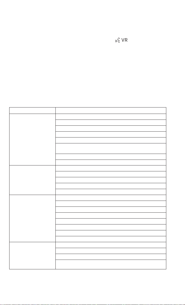
ELECTRONICS
• Start a dialogue by pressing the “Voice Command” button , you will hear a beep.
The beep is your signal to give a command. Below are a list of voice commands for each
of the different modes.
Common Voice Commands (Examples)
While In: Voice Command Example:
“Radio AM” (to switch to the AM radio mode)
“Radio FM” (to switch to the FM radio mode)
“Satellite Radio” (to switch to the Satellite radio mode)
“Disc” (to switch to the disc mode)
Main Menu
Radio Mode
SiriusXM Satellite Radio
Mode
Disc Mode
“Bluetooth Streaming” (to switch to the Bluetooth® Streaming
“Channel Number” (to change the channel by its spoken number)
"Channel Name" (to change the channel by its spoken name)
“USB” (to switch to the USB mode)
mode)
“Memo” (to switch to the memo recorder)
“System Setup” (to switch to system setup)
“Frequency” (to change the frequency)
“Next Station” (to select the next station)
“Previous Station” (to select the previous station)
“Radio Menu” (to switch to the radio menu)
“Main Menu” (to switch to the main menu)
“Next Channel” (to select the next channel)
“Previous Channel” (to select the previous channel)
“List Channel” (to hear a list of available channels)
“Select Name” (to say the name of a channel)
“Radio Menu” (to switch to the radio menu)
“Main Menu” (to switch to the main menu)
“Track” (#) (to change the track)
“Next Track” (to play the next track)
“Previous Track” (to play the previous track)
“Main Menu” (to switch to the main menu)
66
Page 69
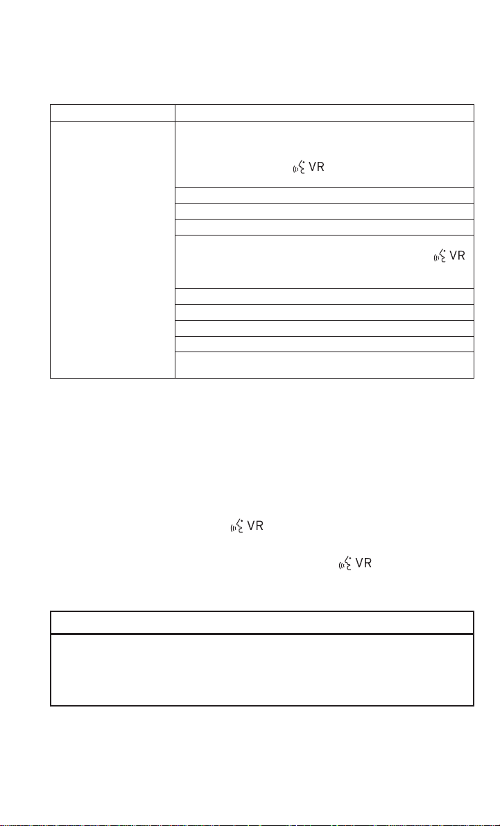
ELECTRONICS
While In: Voice Command Example:
To switch to the voice recorder mode, say “Memo.” The following
are common voice commands for this mode: “New Memo” (to
record a new memo) — During the recording, you may press the
Memo Mode
Voice Command button
— “Play Memos” (to play previously recorded memos) — During
the playback you may press the Voice Command button
to stop playing memos. You proceed by saying one of the follow-
by saying one of the following commands:
— “Save” (to save the memo)
— “Continue” (to continue recording)
— “Delete” (to delete the recording)
— “Repeat” (to repeat a memo)
— “Next” (to play the next memo)
— “Previous” (to play the previous memo)
— “Delete” (to delete a memo)
— “Delete All” (to delete all memos)
Voice Text Reply
• If equipped with Uconnect® Voice Command, your Uconnect® 430N / 730N radio may be
able to play incoming Short Message Service (SMS) messages (text messages) through
the vehicle's sound system.
• It also allows you to respond by selecting from various predefined phrases.
• Not all phones are compatible with this feature. Refer to the phone compatibility list at
www.UconnectPhone.com. Connected mobile phones must be bluetooth-compatible
and paired with your radio.
• Pressthe “VoiceCommand” button
NOTE:
To access the tutorial, press the “Voice Command” button
“tutorial.” Press any hard-key/buttonor touch the display (Touchscreen radio) to cancel the
tutorial.
and after the BEEP, say “SMS” to get started.
to stop recording. You proceed
ing commands:
. After the BEEP, say
WARNING!
Any voice commanded system should be used only in safe driving conditions following
applicable laws regarding phone use. Your attention should be focused on safely operating the vehicle. Failure to do so may result in a collision causing you and others to be
severely injured or killed.
67
Page 70

ELECTRONICS
Bluetooth® STREAMING AUDIO
• If equipped with Uconnect® Voice Command, your Bluetooth®-equipped iPod®
devices, cell phones or other media players, may also be able to stream music to
your vehicles speakers. Your connected
device must be Bluetooth®-compatible,
and paired with your radio (see
www.UconnectPhone.com for pairing instructions).
• Non-Touchscreen Radios: Press the “AUX” button on the radio faceplate until "BT" or
“Audio Streaming” is displayed on the radio screen.
• Touchscreen-Radios:Press the “RADIO/MEDIA” or “MEDIA” hard-key and then touch the
“AUX” soft-key tab.
ELECTRONIC VEHICLE INFORMATION CENTER (EVIC)
• The EVIC features a driver interactive display that is located in the instrument
cluster. Pressing the controls on the left
side of the steering wheel allows the
driver to select vehicle information and
Personal Settings. For additional information, refer to “Programmable Features” located in this guide.
• Press and release the MENU button to
advance the display to Trip Functions or
Personal settings or to return to the default System status display.
• Press and release the DOWN
Functions or Personal Settings.
• Press and release the COMPASS
outside temperature.
• Press and release the SELECT
resets various Trip Functions.
button to advance the display through the various Trip
button to display the compass heading and the
button to accept a selection. The SELECT Button also
68
Page 71

ELECTRONICS
Compass Calibration
• This compass is self-calibrating, which eliminates the need to set the compass manually. When the vehicle is new, the compass may appear erratic and the EVIC will display
“CAL” until the compass is calibrated.
• You may also calibrate the compass by completing one or more 360 degree turns (in an
area free from large metal or metallic objects) until the “CAL” message displayed in the
EVIC turns off. The compass will now function normally.
PROGRAMMABLE FEATURES
Electronic Vehicle Information Center (EVIC)
• The EVIC can be used to program the following Personal Settings. Press and release the
MENU button until Personal Settings displays, then press the DOWN button
through the settings. Press the SELECT button
• Language • Headlights With Wipers
• Auto Unlock On Exit • Key Off Power Delay
• RKE Unlock • Illumin. Approach
• Sound Horn With Lock • Display Units In
• Flash Lamps With Lock • Calibrate Compass
• Headlamp Off Delay • Compass Variance
to change the setting.
(Available with Auto Headlights Only)
to scroll
Key Fob Programmable Features
• The following featuresmay also be programmed by using the Key Fob transmitter or the
ignition switch and driver's door lock switch.
NOTE:
Pressing the LOCK button while you are inside the vehicle will activate the Vehicle Security
Alarm. Opening a door with the Vehicle Security Alarm activated will cause the alarm to
sound. Press the UNLOCK button to deactivate the Vehicle Security Alarm.
Unlock On First Press
• To unlock either the driver's side, or all doors, on the first press of the UNLOCK button:
• Press and hold the LOCK button for at least four seconds, but no longer than 10
seconds. Then, press and hold the UNLOCK button while still holding the LOCK button.
• Release both buttons at the same time.
Auto Unlock Doors On Exit
• To have all of the vehicle doors unlock when any door is opened:
• Enter your vehicle and close all the doors, and fasten your seat belt.
• Cycle the ignition switch between the LOCK and ON position four times, ending in the
LOCK position (do not start the engine).
• Press the power door UNLOCK switch to unlock the doors. A single chime will indicate
that programming is complete.
69
Page 72

ELECTRONICS
Sound Horn With Lock
• To turn the horn chirp on or off when the doors are locked:
• Press the LOCK button for at least four seconds, but no longer than 10 seconds. Then,
press the PANIC button while still holding the LOCK button.
• Release both buttons at the same time.
Flashing Lights With Lock
• The turn signal lights flashing, when the doors are locked or unlocked, feature can be
turned on or off. To turn this feature on or off:
• Press and hold the UNLOCK button for at least four seconds, but no longer than 10
seconds. Then, press and hold the LOCK button while still holding the UNLOCK button.
• Release both buttons at the same time.
UNIVERSAL GARAGE DOOR OPENER (HomeLink®)
• HomeLink® replaces up to three hand-held transmitters that operate devices such as
garage door openers, motorized gates, lighting or home security systems. The
HomeLink® unit is powered by your vehicles 12 Volt battery.
• The HomeLink® buttons that are located in the overhead console or sunvisor designate
the three different HomeLink® channels.
• The HomeLink® indicator is located above the center button.
70
Page 73

ELECTRONICS
Before You Begin Programming HomeLink®
• Ensure that your vehicle is parked outside of the garage before you begin programming.
• Forefficient programming and accurate transmission of the radio-frequency signal, it is
recommended that a new battery be placed in the hand-held transmitter of the device
that is being programmed to the HomeLink® system.
• Erase all channels before you begin programming. To erase the channels, place the
ignition switch into the ON/RUN position, then press and hold the two outside
HomeLink® buttons (I and III) for up to 20 seconds or until the red indicator flashes.
NOTE:
Erasing all channels should only be performed when programming HomeLink® for the first
time. Do not erase channels when programming additional buttons.
• If you have any problems, or require assistance, please call toll-free 1-800-355-3515 or,
on the Internet at www.HomeLink.com for information or assistance.
Programming A Rolling Code
NOTE:
For programming Garage Door Openers that were manufactured after 1995. These Garage
Door Openers can be identified by the “LEARN” or “TRAIN” button located where the
hanging antenna is attachedto the Garage DoorOpener. It is NOT thebutton that is normally
used to open and close the door. The name and color of the button may vary by manufacturer.
1. Place the ignition switch into the ON/RUN position.
2. Place thehand-held transmitter 1 to 3in (3 to 8 cm)away from the HomeLink® button you
wish to program while keeping the HomeLink® indicator light in view.
3. Simultaneously press and hold both the HomeLink® button you want to program and the
hand-held transmitter button.
4. Continue to hold both buttons and observe the indicator light. The HomeLink® indicator
will flash slowly and then rapidly after HomeLink® has received the frequency signal
from the hand-held transmitter. Release both buttons after the indicator light changes
from slow to rapid.
5. At the garage door opener motor (in the garage), locate the “LEARN” or “TRAINING”
button. This can usually be found where the hanging antenna wire is attached to the
garage door opener motor. Firmly press and release the “LEARN” or “TRAINING” button.
NOTE:
You have 30 seconds in which to initiate the next step after the LEARN button has been
pressed.
71
Page 74

ELECTRONICS
6. Return to the vehicle and press the programmed HomeLink® button twice (holding the
button for two seconds each time). If the device is plugged in and activates, programming is complete.
NOTE:
If the device does not activate, press the button a third time (for two seconds) to complete
the training.
7. Toprogram the remaining two HomeLink® buttons, repeat each step for each remaining
button. DO NOT erase the channels.
Programming A Non-Rolling Code
NOTE:
For programming Garage Door Openers manufactured before 1995.
1. Turn the ignition switch to the ON/RUN position.
2. Place the hand-held transmitter 1 to 3 inches (3 to 8 cm) away from the HomeLink®
button you wish to program while keeping the HomeLink® indicator light in view.
3. Simultaneously press and hold both the HomeLink® button you want to program and the
hand-held transmitter button.
4. Continue to hold both buttons and observe the indicator light. The HomeLink® indicator
will flash slowly and then rapidly after HomeLink® has received the frequency signal
from the hand-held transmitter. Release both buttons after the indicator light changes
from slow to rapid.
5. Press andhold the programmed HomeLink® buttonand observe theindicator light. If the
indicator light stays on constantly, programming is complete and the garage door (or
device) should activate when the HomeLink® button is pressed.
6. To program the two remaining HomeLink® buttons, repeat each step for each remaining
button. DO NOT erase the channels.
Using HomeLink®
• To operate, press and release the programmed HomeLink® button. Activation will now
occur for the programmed device (e.g., garage door opener, gate operator, security
system, entry door lock, home/office lighting, etc.,). The hand-held transmitter of the
device may also be used at any time.
WARNING!
• Your motorized door or gate will open and close while you are programming the
universal transceiver.Do not program the transceiver if people or pets are in the path
of the door or gate.
• Do not run your vehicle in a closed garage or confined area while programming the
transceiver. Exhaust gas from your vehicle contains Carbon Monoxide (CO) which is
odorless and colorless. Carbon Monoxide is poisonous when inhaled and can cause
you and others to be severely injured or killed.
72
Page 75

ELECTRONICS
POWER OUTLET
• There are two 12 Volt electrical outlets on
this vehicle.
• The instrument panel power outlet, located below the climate control knobs,
has power available only when the ignition is ON. This power outlet will also operate a conventional cigar lighter unit.
• Thereis also a power outlet located on the
inside of the center console. This power
outlet is powered directlyfrom the battery
(power available at all times). Items
plugged into this power outlet may discharge the battery and/or prevent the engine from starting.
NOTE:
• Do not exceed the maximum power of 160 Watts (13 Amps) at 12 Volts. If the 160 Watt(13
Amp) power rating is exceeded, the fuse protecting the system will need to be replaced.
• Poweroutlets are designed for accessory plugs only.Do not insert any other object in the
power outlet as this will damage the outlet and blow the fuse. Improper use of the power
outlet can cause damage not covered by your new vehicle warranty.
73
Page 76
UTILITY
TRAILER TOWING WEIGHTS (MAXIMUM TR AILER WEIGHT RATINGS)
The following chart provides the maximum trailer weight ratings towable for your given
drivetrain.
Maximum Trailer Weight Ratings
Engine/
Transmission
2.4L/Auto
3.6L/Auto 22 sq. ft. (2.0 sq. m) 1,000 lbs (450 kg) 100 lbs (45 kg)
1
The trailer tongue weightmust be considered as part of the combined weightof occupants
and cargo, and it should never exceed the weight referenced on the Tire and Loading
Information placard.
2
Enclosed trailers or open utility trailers with front shields/guardsare not recommended for
use with four-cylinder engines with an automatic transmission. Please see your authorized
dealer for additional information.
Max. Frontal Area
11 sq ft (1.0 sq.m)
(See Note
Refer to local laws for maximum trailer towing speeds.
2
)
CAUTION!
Towing a trailer with a larger than recommended frontal area could cause the engine to
overheat or cause severe engine damage under extreme conditions.
Max. GTW (Gross
Trailer Wt.)
1,000 lbs (450 kg) 100 lbs (45 kg)
Max. Trailer Tongue
Wt.
1
74
Page 77
UTILITY
RECREATIONAL TOWING (BEHIND MOTORHOME, ETC.)
Towing This Vehicle Behind Another Vehicle
Towing Condition Wheels OFF the
Flat Tow NONE
Dolly Tow
On Trailer ALL OK
Ground
Front OK
Rear
Recreational Towing — All Models
• Recreational towing is allowed ONLY if the front wheels are OFF the ground. This may be
accomplished using a tow dolly or vehicle trailer. If using a tow dolly, follow this procedure:
1. Properly secure the dolly to the tow vehicle, following the dolly manufacturer's instructions.
2. Drive the front wheels onto the tow dolly.
3. Firmly apply the parking brake. Place the transmission in PARK.
4. Properly secure the front wheels to the dolly,following the dolly manufacturer's instruc-
tions.
5. Release the parking brake.
All Models
NOT ALLOWED
NOT ALLOWED
CAUTION!
• DO NOT flat tow this vehicle. Damage to the drivetrain will result.
• Towing this vehicle in violation of the above requirements can cause severe transmission damage. Damage from improper towing is not covered under the New
Vehicle Limited Warranty.
75
Page 78

WHAT TO DO IN EMERGENCIES
ROADSIDE ASSISTANCE
• Dial toll-free 1-800-521-2779 for U.S. Residents or 1-800-363-4869 for Canadian Residents.
• Provide your name, vehicle identification number, license plate number, and your location, including the telephone number from which you are calling.
• Briefly describe the nature of the problem and answer a few simple questions.
• You will be given the name of the service provider and an estimated time of arrival. If you
feel you are in an “unsafe situation”, please let us know. With your consent, we will
contact local police or safety authorities.
INSTRUMENT CLUSTER WARNING LIGHTS
- Electronic Stability Control (ESC) Activation/Malfunction
Indicator Light
• If the “ESC Activation/Malfunction Indicator Light” comes on continuously with the
engine running, a malfunction has been detected in the ESC system. If this light remains
on after several ignition cycles, and the vehicle has been driven several miles (kilometers) at speeds greater than 30 mph (48 km/h), we recommend you do not operate the
vehicle. Have the vehicle serviced immediately.
• The “ESC Activation/Malfunction Indicator Light” starts to flash as soon as the tires lose
traction and the ESC system becomes active. If the light begins to flash during acceleration, ease up on the accelerator and apply as little throttle as possible. Be sure to
adapt your speed and driving to the prevailing road conditions. The light also flashes
when TCS is active. Toimprove the vehicle's traction when starting off in deep snow, sand
or gravel, it may be desirable to switch the ESC system to Partial Off mode by momentarily pressing the ESC Off
switch.
- Electronic Stability Control (ESC) OFF Indicator Light
• This light indicates the Electronic Stability Control (ESC) is off.
- Tire Pressure Monitoring System (TPMS) Light
• Each tire, including the spare (if provided), should be checked monthly, when cold and
inflated to the inflation pressure recommended by the vehicle manufacturer on the
vehicle placard or tire inflation pressure label. (If your vehicle has tires of a different size
than the size indicated on the vehicle placard or tire inflation pressure label, you should
determine the proper tire inflation pressure for those tires.)
• As an added safety feature, your vehicle has been equipped with a Tire Pressure Monitoring System (TPMS) that illuminates a low tire pressure telltale when one or more of
your tires is significantly under-inflated. Accordingly, when the low tire pressure telltale
illuminates, you should stopand check your tires assoon as possible, andinflate them to
the proper pressure. Driving on a significantly under-inflated tire causes the tire to
overheat and can lead to tire failure.Under-inflation also reduces fuel efficiency and tire
tread life, and may affect the vehicle’s handling and stopping ability.
76
Page 79

WHAT TO DO IN EMERGENCIES
• IFTHE LIGHT STARTS FLASHING INDICATING A LOWTIRE PRESSURE, ADJUST THE AIR
PRESSURE IN THE LOW TIRE TO THE AIR PRESSURE SHOWN ON THE VEHICLE PLACARD OR TIRE INFLATION PRESSURE LABEL LOCATED ON THE DRIVER'S DOOR.
NOTE:
AFTER INFLATION,THE VEHICLE MAY NEED TO BE DRIVEN FOR 20 MINUTES BEFORE THE
FLASHING LIGHT WILL TURN OFF.
• Please note that the TPMS is not a substitute for proper tire maintenance, and it is the
driver’s responsibility to maintain correct tire pressure, even if under-inflation has not
reached the level to trigger illumination of the TPMS low tire pressure telltale.
• Your vehicle has also been equipped with a TPMS malfunction indicator to indicate when
the system is not operating properly. The TPMS malfunction indicator is combined with
the low tire pressure telltale. When the system detects a malfunction, the telltale will
flash for approximately one minute and then remain continuously illuminated. This
sequence will continue each time the vehicle is restarted as long as the malfunction
exists.
• When the malfunction indicator is illuminated, the system may not be able to detect or
signal low tire pressure as intended. TPMS malfunctions may occur for a variety of
reasons, including the installation of replacement or alternate tires or wheels on the
vehicle that prevent the TPMS from functioning properly. Always check the TPMS malfunction telltale after replacingone or more tires or wheels on your vehicle, toensurethat
the replacement or alternate tires and wheels allow the TPMS to continue to function
properly.
NOTE:
Tire pressures change by approximately 1 psi (7 kPa) per 12° F (7° C) of air temperature
change. Keep this in mind when checking tire pressure inside a garage, especially in the
Winter. Example: If garage temperature is 68°F (20°C) and the outside temperature is 32°F
(0°C), then the coldtire inflation pressure should be increasedby 3 psi (21 kPa), which equals
1 psi (7 kPa) for every 12°F (7°C) for this outside temperature condition.
CAUTION!
The TPMS has been optimized for the original equipment tires and wheels. TPMS
pressures and warning have been established for the tire size equipped on your vehicle.
Undesirable system operation or sensor damage may result when using replacement
equipment that is notof the same size,type, and/or style. Aftermarket wheelscan cause
sensor damage. Do not use tire sealant from a can, or balance beads if your vehicle is
equipped with a TPMS, as damage to the sensors may result.
77
Page 80
WHAT TO DO IN EMERGENCIES
- Engine Temperature Warning Light
• This light warns of an overheated engine condition.
• If the light turns on or flashes continuously while driving, safely pull over and stop the
vehicle. If the A/C system is on, turn it off. Also, shift the transmission into NEUTRAL and
idle the vehicle. If the temperature reading does not return to normal, turn the engine off
immediately.
• We recommend that you donot operate the vehicle orengine damage will occur.Have the
vehicle serviced immediately.
WARNING!
A hot engine cooling system is dangerous. Youor others could be badly burned by steam
or boiling coolant.
BRAKE
• The Brake Warning light illuminates when there is either a system malfunction or the
parking brake is applied. If the light is on and the parking brake is not applied, it indicates
a possible brake hydraulic malfunction, brake booster problem or an Anti-Lock Brake
System problem.
• Please have your vehicle serviced immediately.
- Brake Warning Light
WARNING!
Driving a vehicle with the red brake light on is dangerous. Part of the brake system may
have failed. It will take longer to stop the vehicle. You could have a collision. Have the
vehicle checked immediately.
- Malfunction Indicator Light (MIL)
• Certain conditions, such as a loose or missing gas cap, poor fuel quality, etc., may
illuminate the MIL after engine start. The vehicle should be serviced if the light stays on
through several typical driving cycles. In most situations, the vehicle will drive normally
and not require towing.
• If the MIL flashes when the engine is running, serious conditions may exist that could
lead to immediate loss of power or severe catalytic converter damage. We recommend
you do not operate the vehicle. Have the vehicle serviced immediately.
- Charging System Light
• Thislight shows the status of the electrical charging system.If the charging system light
remains on, it means that the vehicle is experiencing a problem with the charging
system.
• We recommend you do not continue driving if the charging system light is on. Have the
vehicle serviced immediately.
78
Page 81
WHAT TO DO IN EMERGENCIES
- Oil Pressure Warning Light
• This light indicates low engine oil pressure. If the light turns on while driving, stop the
vehicle and shut off the engine as soon as possible. A chime will sound when this light
turns on.
• We recommend you do not operate the vehicle or engine damage will occur. Have the
vehicle serviced immediately.
- Anti-Lock Brake (ABS) Light
• This light monitors the Anti-Lock Brake System (ABS).
• Ifthe light is not onduring starting, stays on, orturns on while driving, werecommend you
drive to the nearest authorized dealer and have the vehicle serviced immediately.
- Electronic Throttle Control (ETC) Indicator Light
• This light informs you of a problem with the system.
• If a problem is detected, the light will come on while the engine is running. Cycle the
ignition when the vehicle has completely stopped and the shift lever is placed in the
PARK position; the light should turn off.
• If the light remains lit with the engine running, your vehicle will usually be drivable;
however, see an authorized dealer immediately. If the light is flashing when the engine is
running, immediate service is required and you may experience reduced performance,
an elevated/rough idle or engine stall and your vehicle may require towing.
- Transmission Temperature Warning Light
• This light indicates that there is excessive transmission fluid temperature that might
occur with severe usage such as trailer towing. If this light turns on, stop the vehicle and
run the engine at idle, with the transmission in NEUTRAL, until the light turns off. Once
the light turns off, you may continue to drive normally.
CAUTION!
Continuous driving with the Transmission Temperature Warning Light illuminated will
eventually cause severe transmission damage or transmission failure.
WARNING!
If you continue operating the vehicle when the TransmissionTemperature Warning Light
is illuminated you could cause the fluid to boil over, come in contact with hot engine or
exhaust components and cause a fire.
79
Page 82

WHAT TO DO IN EMERGENCIES
- Air Bag Warning Light
• If the light is not on during starting, stays on, or turns on while driving, have the vehicle
serviced by an authorized dealer immediately.
Fuel Cap/Loose Gas Cap Message
• If a “gas cap” message (shown as Check Fuel Cap) appears, tighten the gas cap until a
“clicking” sound is heard.
• Press the odometer reset button to turn the message off.
• Ifthe message continues to appearformorethan three days after tightening thegas cap,
see your authorized service center.
Oil Change Indicator
Message
• If an “oil change” message (shown as CHANgE OIL) appears and a single chime sounds,
it is time for your next required oil change.
Resetting The Light After Servicing
• Turn the ignition switch to the ON/RUN position (do not start engine).
• Fully depress the accelerator pedal three times within 10 seconds.
• Turn the ignition switch to the OFF/LOCK position.
IF YOUR ENGINE OVERHEATS
• In any of the following situations, you can reduce the potential for overheating by taking
the appropriate action.
• On the highways — slow down.
• In city traffic — while stopped, shift transmission into NEUTRAL, but do not increase
engine idle speed.
NOTE:
There are steps that you can take to slow down an impending overheat condition:
• If your air conditioner (A/C) is on, turn it off. The A/C system adds heat to the engine
cooling system and turning the A/C off can help remove this heat.
• You can also turn the Temperature Control to maximum heat, the Mode Control to floor
and the Fan Control to high. This allows the heater core to act as a supplement to the
radiator and aids in removing heat from the engine cooling system.
• If the temperature reading does not return to normal, turn the engine off immediately.
• We recommend that you donot operate the vehicle orengine damage will occur.Have the
vehicle serviced immediately.
80
Page 83
WHAT TO DO IN EMERGENCIES
Engine Oil Overheating — 2.4L Gas
• On hot days the engine oil temperature may become too hot during sustained highspeed driving or if towing a trailer up long grades. If this happens, a HOTOIL message will
flash in the odometer and the vehicle speed will be reduced to 48 mph (77 km/h)
maximum until the engine oil temperature is reduced.
NOTE:
Although the maximum vehicle speed is reduced to 48 mph (77 km/h), you may reduce
vehicle speed further as needed. Once the engine oil temperature is reduced, you may
continue to drive normally.
CAUTION!
Driving with a hot cooling system could damage your vehicle. If the temperature gauge
reads HOT (H), pull over and stop the vehicle. Idle the vehicle with the air conditioner turned
off until the pointer drops back into the normal range. If the pointer remains on HOT (H), and
you hear continuous chimes, turn the engine off immediately, and call for service.
WARNING!
You or others can be badly burned by hot engine coolant (antifreeze) or steam from your
radiator. If you see orhear steam coming fromunderthe hood, do not open the hood until
the radiator has had time to cool. Never try to open a cooling system pressure cap when
the radiator or coolant bottle is hot.
JACKING AND TIRE CHANGING
Jack Location
• The jack and jack-handle are stowed under the load floor in the trunk.
Spare Tire Stowage
• The compact spare tire is stowed under the rear load floor in the trunk.
Spare Tire Removal
• Lift up the load floor cover and remove the hold down.
81
Page 84

WHAT TO DO IN EMERGENCIES
Preparations For Jacking
1. Park the vehicle on a firm, level surface. Avoid ice or slippery areas.
2. Turn on the Hazard Warning flashers.
3. Set the parking brake.
4. Place the shift lever into PARK (automatic transmission) or REVERSE (manual transmission).
5. Turn OFF the ignition.
6. Block both the front and rear of the wheel diagonally opposite the jacking position. For
example, if changing the right front tire, block the left rear wheel.
NOTE:
Passengers should not remain in the vehicle
while the vehicle is being jacked.
Jacking Instructions
1. Remove the scissors jack and lug wrench
from the spare wheel as an assembly.
Turn the jack screw to the left to loosen
the lug wrench, and remove the wrench
from the jack assembly.
82
Page 85

WHAT TO DO IN EMERGENCIES
NOTE:
The jack handle attaches to the side of the jack with two attachment points. When the jack
is partially expanded, the tensionbetween the twoattachment points holds the jack handle
in place.
2. Loosen, but do not remove, the wheel
nuts by turning them to the left one turn
while the wheel is still on the ground.
3. There is a front and rear jacking location on each side of the vehicle.
4. Turn the jack screw to the left until the jack can be placed under the jacking location.
Once the jack is positioned, turn the jack screw to the right until the jack head is properly
engaged with the lift area closest to the wheel to be changed. Do not raise the vehicle
until you are sure the jack is securely engaged.
5. Raise the vehicleby turning the jack screwtothe right, using the swivelwrench.Raise the
vehicle only until the tire just clears the surface and enough clearance is obtained to
install the spare tire. Minimum tire lift provides maximum stability.
83
Page 86

WHAT TO DO IN EMERGENCIES
6. Remove the wheel nuts, and pull the wheel and wheel covers (where applicable) off the
hub. Install the spare wheel and wheel nuts with the cone shaped end of the nuts toward
the wheel. Lightly tighten the nuts.
7. Lower the vehicle by turning the jack
screw to the left.
8.
Finish tightening the nuts. Push down on
the wrench while atthe end of thehandle for
increased leverage. Tighten the lug nuts in a
star pattern until each nut has been tightened twice. The correct wheel nut torque is
100 ft lbs (135 N·m). If you doubt that you
have tightened the nuts correctly, have
them checked with a torque wrench by your
authorized dealer or at a service station.
9. Remove the wheel blocks and lower the jack until it is free. Reassemble the lug wrench
to the jack assembly and stow it in the spare tire area. Secure the assembly using the
means provided.
10. Place the deflated (flat) tire in the cargo area and have the tire repaired or replaced as
soon as possible.
11. Check the tire pressure as soon as possible. Correct the tire pressure as required.
Road Tire Installation
Vehicles Equipped With Wheel Covers
1. Mount the road tire on the axle.
2. To ease the installation process for steel wheels with wheel covers, install two lug nuts
on the mounting studs which are on each side of the valvestem. Install the lug nuts with
the cone shaped end of the nut toward the wheel. Lightly tighten the lug nuts.
84
1 — Valve Stem 4 — Wheel Cover
2 — Valve Notch 5 — Mounting Stud
3 — Wheel Lug Nut
Page 87

WHAT TO DO IN EMERGENCIES
3. Align the valve notch in the wheel cover with the valve stem on the wheel. Install the
cover by hand, snapping the cover over the two lug nuts. Do not use a hammer or
excessive force to install the cover.
4. Install the remaining lug nuts with the cone shaped end of the nut toward the wheel.
Lightly tighten the lug nuts.
5. Lower the vehicle to the ground by turning the jack handle counterclockwise.
6. Finish tighteningthe lug nuts. Push downon the wrench while at theend of the handlefor
increased leverage. Tighten the lug nuts in a star pattern until each nut has been
tightened twice. The correct tightness of each lug nut is 100 ft/lbs (135 N·m). If in doubt
about the correct tightness, have them checkedwith a torque wrenchby your authorized
dealer or service station.
7. After 25 miles (40 km) check the lug nut torque with a torque wrench to ensurethat all lug
nuts are properly seated against the wheel.
Vehicles Without Wheel Covers
1. Mount the road tire on the axle.
2. Install the remaining lug nuts with the cone shaped end of the nut toward the wheel.
Lightly tighten the lug nuts.
3. Lower the vehicle to the ground by turning the jack handle counterclockwise.
4. Finish tightening thelug nuts. Push down onthe wrench while at theend of the handlefor
increased leverage. Tighten the lug nuts in a star pattern until each nut has been
tightened twice. The correct tightness of each lug nut is 100 ft/lbs (135 N·m). If in doubt
about the correcttightness, have them checked with a torquewrench by your authorized
dealer or service station.
5. After 25miles (40 km) check thelug nut torque with atorque wrench to ensure that all lug
nuts are properly seated against the wheel.
CAUTION!
• Do not attempt to raise the vehicle by jacking on locations other than those indicated
in the Jacking Instructions for this vehicle.
• Be sure to mount the spare tirewith the valve stem facing outward.The vehicle could
be damaged if the spare tire is mounted incorrectly.
85
Page 88

WHAT TO DO IN EMERGENCIES
WARNING!
• Being under a jacked-up vehicle is dangerous. The vehicle could slip off the jack and
fall on you. You could be crushed. Never put any part of yourbody under a vehicle that
is on a jack. If you need to get under a raised vehicle, takeit to a service center where
it can be raised on a lift.
• Never start or run the engine while the vehicle is on a jack.
• The jack is designed to be used as a tool for changing tires only. The jack should not
be used to lift the vehicle for service purposes. The vehicleshould be jacked ona firm
level surface only. Avoid ice or slippery areas.
• Do not attempt to change a tire on the side of the vehicle close to moving traffic, pull
far enough off the road to avoid the danger of being hit when operating the jack or
changing the wheel.
• Carefully follow these tire changing warnings to help prevent personal injury or
damage to your vehicle:
• Always park on a firm, level surface as far from the edge of the roadway as pos-
sible before raising the vehicle.
• Turn on the Hazard Warning flasher.
• Block the wheel diagonally opposite the wheel to be raised.
• Set the parking brake firmly and set an automatic transmission in PARK; a
manual transmission in REVERSE.
• Do not let anyone sit in the vehicle when it is on a jack.
• Do not get under the vehicle when it is on a jack.
• Only use the jack in the positions indicated and for lifting this vehicle during a tire
change.
• If working on or near a roadway, be extremely careful of motor traffic.
• To assure that spare tires, flat or inflated, are securely stowed, spares must be
stowed with the valve stem facing the ground.
• Raising the vehicle higher than necessary can make the vehicle less stable. It could
slip off the jack and hurt someone near it. Raise the vehicle only enough to remove
the tire.
• To avoid possible personal injury,handle the wheel covers with care to avoid contact
with any sharp edges.
• A loose tire or jack thrown forward in a collision or hard stop could injure the
occupants in the vehicle. Have the deflated (flat) tire repaired or replaced immediately.
• To avoid the risk of forcing the vehicle off the jack, do not tighten the lug nuts fully
until the vehicle is lowered to the ground. Failure to follow this warning may result in
personal injury.
86
Page 89

WHAT TO DO IN EMERGENCIES
BATTERY LOCATION
• The battery in your vehicle is located between the left front headlight assembly and the
left front wheel splash shield. To allow jump-starting there are remote battery posts
located on the left side of the engine compartment.
JUMP-STARTING
• If your vehicle has a discharged battery it can be jump-started using a set of jumper
cables and a battery in another vehicle or by using a portable battery booster pack.
Jump-starting can be dangerous if done improperly so please follow the procedures in
this section carefully.
NOTE:
When using a portable battery booster pack follow the manufacturer's operating instructions and precautions.
87
Page 90

WHAT TO DO IN EMERGENCIES
Preparations For Jump-Start
• The battery in your vehicle is located between the left front headlight assembly and the
left front wheel splash shield. To allow jump-starting there are remote battery posts
located on the left side of the engine compartment.
1. Set the parking brake, shift the automatic
transmission into PARK and turn the ignition to LOCK.
2. Turn off the heater, radio, and all unnec-
essary electrical accessories.
3. Remove the protective cover over the re-
mote positive (+) battery post. To remove
the cover, press the locking tab and pull
upward on the cover.
4. If using another vehicle to jump-start the
battery, park the vehicle within the
jumper cables reach, set the parking
brake and make sure the ignition is OFF.
1 — Positive Jump Starting Post
2 — Negative Jump Starting Post
Jump-Starting Procedure
1. Connect the positive (+) end of the jumper cable to the remote positive (+) post of the
discharged vehicle.
2. Connect the opposite end of the positive (+) jumper cable to the positive (+) post of the
booster battery.
3. Connect the negative end (-) of the jumper cable to the negative (-) post of the booster
battery.
4. Connect the opposite end ofthe negative (-) jumper cable to the remote negative (-) post
of the vehicle with the discharged battery.
5. Star t the engine in the vehicle that has the booster battery, let the engine idle a few
minutes, and then start the engine in the vehicle with the discharged battery.
Once the engine is started, remove the jumper cables in the reverse sequence:
1. Disconnect the negative (-) jumper cable from the remote negative (-) post of the vehicle
with the discharged battery.
2. Disconnect the negative end (-) of the jumper cable from the negative (-) post of the
booster battery.
3. Disconnect the opposite end of the positive (+) jumper cable fromthe positive (+)post of
the booster battery.
88
Page 91
WHAT TO DO IN EMERGENCIES
4. Disconnect the positive (+) end of the jumper cable from the remote positive (+) post of
the discharged vehicle.
5. Reinstall the protective cover over the remote positive (+) battery post of the discharged
vehicle.
NOTE:
If frequent jump-starting is required to start your vehicle you should have the battery and
charging system inspected at your authorized dealer.
CAUTION!
• Do not use a portable batter y booster pack or any other booster source with a system
voltage greater than 12 Volts or damage to the battery, starter motor, alternator or
electrical system may occur.
• Failure to follow these procedures could result in damage to the charging system of
the booster vehicle or the discharged vehicle.
• Accessories that can be plugged into the vehicle power outlets draw power from the
vehicle’s battery, even when not in use (e.g., cellular phones, etc.). Eventually, if
plugged in long enough, the vehicle’s battery discharges sufficiently to degrade
battery life and/or prevent the engine from starting.
WARNING!
• When temperatures are below the freezing point, electrolyte in a discharged battery
may freeze. Do not attempt jump-starting because the battery could rupture or
explode and cause personal injury. Battery temperature must be brought above the
freezing point before attempting a jump-start.
• Take care to avoid the radiator cooling fan whenever the hood is raised. It can start
anytime the ignition switch is on. You can be injured by moving fan blades.
• Remove any metal jewelry, such as watch bands or bracelets, that might make an
inadvertent electrical contact. You could be severely injured.
• Batteries contain sulfuric acid thatcan burn your skin or eyes and generate hydrogen
gas which is flammable and explosive. Keep open flames or sparks away from the
battery.
• Do notallow vehicles to touch each other as this couldestablish a ground connection
and personal injury could result.
• Failure to follow this procedure could result in personal injury or property damage
due to battery explosion.
• Do not connect the cable to the negative post (-) of the discharged battery. The
resulting electrical spark could cause the battery to explode and could result in
personal injury.
89
Page 92

WHAT TO DO IN EMERGENCIES
SHIFT LEVER OVERRIDE
• Ifa malfunction occurs andthe shift lever cannotbe moved out ofthe PARKposition, you
can use the following procedure to temporarily move the shift lever:
1. Turn the engine OFF.
2. Firmly apply the parking brake.
3. Remove the rubber cupholder liner. Squeeze one side of the liner’s center to expose its
edge and facilitate removal.
4. Turn the ignition to the ACC or ON/RUN position, but do not start the engine.
5. Press and maintain firm pressure on the brake pedal.
6. Inser t a screwdriver or similar tool into the access hole (at the front ofthe cupholder) and
push and hold the override release lever forward.
7. Move the shift lever to the NEUTRAL position.
8. The vehicle may then be started in NEUTRAL.
9. Reinstall the cupholder liner.
90
Page 93

Flatbed Towing (all four
WHAT TO DO IN EMERGENCIES
wheels suspended OFF the
ground)
Front Wheels Raised, Rear
Wheels on the Ground
Rear Wheels Raised, Front
Wheels on the Ground
on the ground)
Model Flat Towing (all four wheels
TOWING A DISABLED VEHICLE
May Be Used Recommended Method
front end dolly
NOT Permitted NOT Permitted without a
FWDWithoutaKey
May Be Used Recommended Method
Shift lever must be in NEUTRAL. The distance to be trav-
eled must not exceed 15 mi (25 km), and the towing speed
FWDWithaKey
must not exceed 25 mph (40 km/h).
91
Page 94
WHAT TO DO IN EMERGENCIES
FREEING A STUCK VEHICLE
• If your vehicle becomes stuck in mud, sand or snow, it can often be moved by a rocking
motion. Turn your steering wheel right and left to clear the area around the front wheels.
Then move the shift lever back and forth between REVERSE and DRIVE. Using minimal
accelerator pedal pressure to maintain the rocking motion, without spinning the wheels,
is most effective.
NOTE:
To improve the vehicle's traction when starting off in deep snow, sand or gravel, it may be
desirable to switch the Electronic Stability Control (ESC) to “Partial Off” mode by momentarily pressing the ESC Off
Manual on the DVD.
• When “rocking” a stuck vehicle by shifting between REVERSE and DRIVE, do not spin
the wheels faster than 15 mph (24 km/h), or drivetrain damage may result.
• Revving the engine or spinning the wheels too fast may lead to transmission overheating and failure. It can also damage the tires. Do not spin the wheels above
30 mph (48 km/h) while in gear (no transmission shifting occurring).
Fast spinning tires can be dangerous. Forces generated by excessive wheel speeds may
cause tire damage or failure. A tire could explode and injure someone. Do not spin your
vehicle's wheels faster than 30 mph (48 km/h) when you are stuck. Do not let anyone
near a spinning wheel, no matter what the speed.
switch. For further information on ESC, refer to the Owner's
CAUTION!
WARNING!
92
Page 95

WHAT TO DO IN EMERGENCIES
EVENT DATA RECORDER (EDR)
• This vehicle is equipped with an Event Data Recorder (EDR). The main purpose of an EDR
is to record, in certain crash or near crash-like situations, such as an air bag deployment
or hitting a road obstacle, data that will assist in understanding how a vehicle’s systems
performed. The EDR is designed to record data related to vehicle dynamics and safety
systems for a short period of time, typically 30 seconds or less. The EDR in this vehicle is
designed to record such data as:
• How various systems in your vehicle were operating.
• Whether or not the driver and passenger safety belts were buckled/fastened.
• How far (if at all) the driver was depressing the accelerator and/or brake pedal.
• How fast the vehicle was traveling.
• These data can help provide a better understanding of the circumstances in which
crashes and injuries occur.
NOTE:
EDR data is recorded by your vehicle only if a non-trivial crash situation occurs; no data is
recorded by the EDR under normal driving conditions and no personal data (e.g. name,
gender, age, and crash location) is recorded. However, other parties, such as law enforcement, could combine the EDR data with the type of personally identifying data routinely
acquired during a crash investigation.
• To read data recorded by an EDR, special equipment is required, and access to the
vehicle or the EDR is needed. In addition to the vehicle manufacturer, other parties such
as law enforcement, that have the special equipment, can read the information if they
have access to the vehicle or the EDR.
93
Page 96

MAINTAINING YOUR VEHICLE
OPENING THE HOOD
1. Pull the release lever located below the
instrument panel and in front of the driver’s door.
2. Raise the hood and locate the safety
latch, in the middle of the hood opening.
3. Move the safety latch while lifting the
hood at the same time.
4. Insert the support rod into the slot on the
hood.
5. To close the hood, remove the support
rod and place it in the retaining clip, then
lower the hood slowly.
WARNING!
Be sure the hood is fully latched before driving your vehicle. If the hood is not fully
latched, it could open when the vehicle is in motion and block your vision. Failure to
follow this warning could result in serious injury or death.
94
Page 97
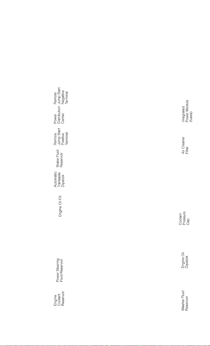
MAINTAINING YOUR VEHICLE
ENGINE COMPARTMENT
2.4L Engine
95
Page 98
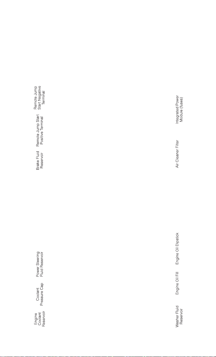
MAINTAINING YOUR VEHICLE
3.6L Engine
96
Page 99

MAINTAINING YOUR VEHICLE
FLUIDS AND CAPACITIES
Component Fluid, Lubricant, or Genuine
We recommend you use
Engine Coolant – 2.4L Engine
Engine Coolant – 3.6L Engine
Engine Oil with Filter – 2.4L
Engine
Engine Oil with Filter – 3.6L
Engine
Fuel Selection – All Engines
(Except 2.4L PZEV)
Fuel Selection – 2.4L PZEV
Engine
Engine Oil Filter
Spark Plugs 2.4L – Except
PZEV Engine
Spark Plugs 2.4L – With PZEV
Engine
Spark Plugs – 3.6L Engine
MOPAR® Antifreeze/Coolant
10 Year/150,000 Mile Formula
OAT (Organic Additive Tech-
We recommend you use
MOPAR® Antifreeze/Coolant
10 Year/150,000 Mile Formula
OAT (Organic Additive Tech-
We recommend you use API
Certified SAE 5W-20 Engine
Oil, meeting the requirements
of Chrysler Material Standard
MS- 6395 such as MOPAR®,
Pennzoil®, and Shell Helix ®.
Refer to your engine oil filler
cap for correct SAE grade.
We recommend you use API
Certified SAE 5W-20 Engine
Oil, meeting the requirements
of Chrysler Material Standard
MS- 6395 such as MOPAR®,
Pennzoil®, and Shell Helix ®.
Refer to your engine oil filler
cap for correct SAE grade.
We recommend you use
MOPAR® brand Engine Oil
We recommend you use
MOPAR® Spark Plugs (Gap
We recommend you use
MOPAR® Spark Plugs (Gap
We recommend you use
MOPAR® Spark Plugs (Gap
Part
nology).
nology).
87 Octane
87 Octane
Filters.
0.043 in [1.1 mm]).
0.031 in [0.8 mm]).
0.043 in [1.1 mm]).
Capacities
7.7 Quarts (7.3 Liters) Includes
heater and coolant recovery
bottle filled to MAX level.
11.6 Quarts (11 Liters) Includes
heater and coolant recovery
bottle filled to MAX level.
4.5 Quarts (4.26 Liters)
6 Quarts (5.6 Liters)
16.9 Gallons (64 Liters)
(Approximate)
18.5 Gallons (70 Liters)
(Approximate)
—
—
—
—
97
Page 100
MAINTAINING YOUR VEHICLE
Component Fluid, Lubricant, or Genuine
Use only ATF+4® Automatic
Transmission Fluid. Failure to
Automatic Transmission
Brake Master Cylinder
Power Steering Reservoir
use ATF+4® fluid may affect
the function or performance
of your transmission. We rec-
ommend MOPAR® ATF+4®
We recommend you use
MOPAR® DOT 3 and SAE
J1703. If DOT 3 is not available, then DOT 4 is accept-
We recommend you use
MOPAR® Power Steering Fluid
+ 4 or MOPAR® ATF+4® Auto-
matic Transmission Fluid.
Part
fluid.
able.
Capacities
—
—
—
CAUTION!
• Mixing of engine coolant (antifreeze) other than specified Organic Additive Technology (OAT) engine coolant (antifreeze), may result in engine damage and may decrease corrosion protection. Organic Additive Technology (OAT) engine coolant is
different and should not be mixed with Hybrid Organic Additive Technology (HOAT)
engine coolant (antifreeze) or any “globally compatible” coolant (antifreeze). If a
non-OAT engine coolant (antifreeze) is introduced into the cooling system in an
emergency, the cooling system will need to be drained, flushed, and refilled with
fresh OAT coolant (conforming to MS-12106), by an authorized dealer as soon as
possible.
• Do not use water aloneor alcohol-based enginecoolant (antifreeze) products. Donot
use additional rust inhibitors or antirust products, as they may not be compatible
with the radiator engine coolant and may plug the radiator.
• This vehicle has not been designed for use with propylene glycol-based engine
coolant (antifreeze). Use of propylene glycol-basedengine coolant (antifreeze)is not
recommended.
E85 FLEXIBLE FUEL — 3.6L ENGINE ONLY
Refer to your Owner's Manual on the DVD for further details.
CAUTION!
Only vehicles with the E-85 fuel filler door label or a yellow gas cap can operate on E-85.
98
 Loading...