

Page 1
Harman Music Group Inc.
Master Level
0-99 Level
Reverb
1-3 Room
4-6 Hall
7-9 Arena
Mono Delay
1-9 100ms
11-19 200ms
21-29 250ms
31-39 300ms
41-49 350ms
51-59 400ms
61-69 500ms
Multi Delay
1-9 Pong 100/200ms
11-19 Pong 150/300ms
21-29 Pong 200/400ms
31-39 Pong 250/500ms
41-49 Taps 100/300ms
51-59 Taps 200/300ms
61-69 Taps 300/400ms
71-79 Taps 400/500ms
Pitch/Detune
1 Octabass
8 3rd
2 Oct
9 4th
bb
3 6th
10 5th
4 6th
11 Oct
5 5th
12-14 5 Cents
6 4th
15-17 10 Cents
b
7 3rd
18-20 15 Cents
Pha/Tre/More
1-4 Phase Slow
5-8 Phase Medium
9-12 Phase Fast
13-21 Tremolo
22-28 Ring Modulator
29-40 Pixellator
Chorus/Flange
1-4 Chorus Slow
5-8 Chorus Medium
9-12 Chorus Fast
13-16 Flange Slow
17-20 Flange Medium
21-24 Flange Fast
Low EQ
Noise Gate Mid EQ
1-8 Gate Threshold
12 dB Boost -2 dB Cut
9-11 Fast Swell
10 dB Boost -4 dB Cut
12-14 Slow Swell
8 dB Boost -6 dB Cut
6 dB Boost -8 dB Cut
4 dB Boost -10 dB Cut
2 dB Boost -12 dB Cut
0 Flat
12 dB Boost -2 dB Cut
10 dB Boost -4 dB Cut
8 dB Boost -6 dB Cut
6 dB Boost -8 dB Cut
4 dB Boost -10 dB Cut
2 dB Boost -12 dB Cut
0 Flat
PGM#BANK
23
High EQ
12 dB Boost -2 dB Cut
10 dB Boost -4 dB Cut
8 dB Boost -6 dB Cut
6 dB Boost -8 dB Cut
4 dB Boost -10 dB Cut
2 dB Boost -12 dB Cut
0 Flat
Data
Distortion
1-10 IT
11-20 Grind
21-30 Fuzz
31-40 FuzzIT
41-50 IT (Spkr Sim)
51-60 Grind (Spkr Sim)
61-70 Fuzz (Spkr Sim)
71-80 Fuzz IT (Spkr Sim)
Compressor
1-10 Comp Amount
Expression
1 Volume
2 Wah
3 Auto Wah
4 Mod Speed
5 Mod Depth
6 Mod Level
7 Detune
8 Pitch/Detune Level
Owner’s Guide
Introduction
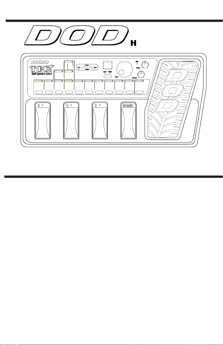
Welcome to the world of the DOD TEC8! You have purchased the finest
guitar signal processor and preamp of its kind; hardly a surprise when it
comes from DOD. The TEC8 gives you both functional flexibility and tonal
excellence, driven by our proven effects processing technology.
Specifications
Up to 8 effects at a time
Ergonomic look and feel
Built-in effect Expression Pedal
Analog IT™ and Grind Distortions
3-band EQ
Effects include: Compressor, 8 Analog Distortions, Noise Gate, Chorus,
Flanger, Phaser, Tremolo, Ring Modulator, Pixellator, Pitch, Shift, Detune,
Mono and Tap Delays, Reverb
Easy-to-use interface
30 User, 30 Factory Presets
Jam-a-long™ Jack
A/D Resolution: 18 Bit
D/A Resolution: 16 Bit
DSP: 24 bit
Frequency Response: 20Hz to 16kHz
Signal to Noise Ratio: -87dB
Power Supply: DOD PS750, 9 VAC @ 750 ma
9 Delay Level
10 Reverb Level
Page 2

IMPORTANT!
FOR YOUR PROTECTION, PLEASE READ THE FOLLOWING:
WATER AND MOISTURE: Appliance should not be used near water (e.g. near a bathtub, washbowl,
kitchen sink, laundry tub, in a wet basement, or near a swimming pool, etc). Care should be taken so
that objects do not fall on and liquids are not spilled into the enclosure through openings.
POWER SOURCES: The appliance should be connected to a power supply only of the type described
in the operating instructions or as marked on the appliance.
GROUNDING OR POLARIZATION: Precautions should be taken so that the grounding or polarization
means of an appliance is not defeated.
POWER CORD PROTECTION: Power supply cords should be routed so that they are not likely to be
walked on or pinched by items placed upon or against them, paying particular attention to cords at
plugs, convenience receptacles, and the point where they exit from the appliance.
SERVICING: The user should not attempt to service the appliance beyond that described in the operating instructions. All other servicing should be referred to qualified service personnel.
FUSING: If your unit is equipped with a fuse receptacle, replace with only same type fuse. Refer to
replacement text on the unit for correct fuse type.
Warranty
1. The warranty registration card must be mailed within ten days after purchase date to
validate this warranty.
2. DOD warrants this product, when used solely within the U.S., to be free from defects
in materials and workmanship under normal use and service.
3. DOD liability under this warranty is limited to repairing or replacing defective materials
that show evidence of defect, provided the product is returned to DOD WITH
RETURN AUTHORIZATION, where all parts and labor will be covered up to a period
of two (2) years. A Return Authorization number may be obtained from DOD by telephone. The company shall not be liable for any consequential damage as a result of
the product’s use in any circuit or assembly.
4. Proof-of-purchase is considered to be the burden of the consumer.
5. DOD reserves the right to make changes in design or make additions to or improvements upon this product without incurring any obligation to install the same on products previously manufactured.
6. The foregoing is in lieu of all other warranties, expressed or implied, and DOD neither
assumes nor authorizes any person to assume for it any obligation or liability in connection with the sale of this product. In no event shall DOD or its dealers be liable for
special or consequential damages or from any delay in the performance of this warranty due to causes beyond their control.
DOD® and TEC8™ are registered trademarks of DOD Electronics Corporation.
The information contained in this manual is subject to change at any time without notifi-
cation. Some information contained in this manual may also be inaccurate due to undocumented changes in the product or operating system since this version of the manual was
completed. The information contained in this version of the owner's manual supersedes
all previous versions.
Page 3

Signal Processing
SECTION 1 - GETTING STARTED . . . . . . . . . . . . . . . . . . . . . . . . . . . . . . . . . . .2
Front Panel Controls . . . . . . . . . . . . . . . . . . . . . . . . . . . . . . . . . . . . . . . . . . . .2
PROGRAM AND BANK SELECTOR FOOTSWITCHES . . . . . . . . . . . . . . . . . . .2
EFFECT SELECTOR BUTTONS (DIGITAL FX) . . . . . . . . . . . . . . . . . . . . . . . . .2
EFFECT GROUPS . . . . . . . . . . . . . . . . . . . . . . . . . . . . . . . . . . . . . . . . . . . .2
EFFECT SELECTOR BUTTONS (PREAMP) . . . . . . . . . . . . . . . . . . . . . . . . . . .2
STORE BUTTON . . . . . . . . . . . . . . . . . . . . . . . . . . . . . . . . . . . . . . . . . . . . .2
DISPLAY . . . . . . . . . . . . . . . . . . . . . . . . . . . . . . . . . . . . . . . . . . . . . . . . .2
DATA WHEEL . . . . . . . . . . . . . . . . . . . . . . . . . . . . . . . . . . . . . . . . . . . . . . .2
CLIP LED . . . . . . . . . . . . . . . . . . . . . . . . . . . . . . . . . . . . . . . . . . . . . . . . .3
OUTPUT KNOB . . . . . . . . . . . . . . . . . . . . . . . . . . . . . . . . . . . . . . . . . . . . .3
INPUT KNOB . . . . . . . . . . . . . . . . . . . . . . . . . . . . . . . . . . . . . . . . . . . . . . .3
EXPRESSION ASSIGN . . . . . . . . . . . . . . . . . . . . . . . . . . . . . . . . . . . . . . . . .3
Rear Panel Connections . . . . . . . . . . . . . . . . . . . . . . . . . . . . . . . . . . . . . . . . .3
INSTRUMENT INPUT . . . . . . . . . . . . . . . . . . . . . . . . . . . . . . . . . . . . . . . . .3
JAM-A-LONG™ INPUT . . . . . . . . . . . . . . . . . . . . . . . . . . . . . . . . . . . . . . . .3
HEADPHONE OUTPUT . . . . . . . . . . . . . . . . . . . . . . . . . . . . . . . . . . . . . . . .3
LEFT / MONO OUT . . . . . . . . . . . . . . . . . . . . . . . . . . . . . . . . . . . . . . . . . .3
RIGHT OUT . . . . . . . . . . . . . . . . . . . . . . . . . . . . . . . . . . . . . . . . . . . . . . . .3
AC POWER INPUT . . . . . . . . . . . . . . . . . . . . . . . . . . . . . . . . . . . . . . . . . . .3
POWER CORD STRAIN RELIEF . . . . . . . . . . . . . . . . . . . . . . . . . . . . . . . . . . .3
Hooking Up and Supplying Power . . . . . . . . . . . . . . . . . . . . . . . . . . . . . . . . .4
SECTION 2 - PROGRAMMING THE TEC8 . . . . . . . . . . . . . . . . . . . . . . . . . . . . .5
Navigating The TEC8 . . . . . . . . . . . . . . . . . . . . . . . . . . . . . . . . . . . . . . . . . . .5
Selecting Programs in the TEC8 . . . . . . . . . . . . . . . . . . . . . . . . . . . . . . . . .5
User LED Indicator . . . . . . . . . . . . . . . . . . . . . . . . . . . . . . . . . . . . . . . . . . .5
Using The Footswitches . . . . . . . . . . . . . . . . . . . . . . . . . . . . . . . . . . . . . . . . .5
Selecting Programs using the footswitches . . . . . . . . . . . . . . . . . . . . . . . . .5
Editing Programs . . . . . . . . . . . . . . . . . . . . . . . . . . . . . . . . . . . . . . . . . . . . . .6
Expression Pedal Assign . . . . . . . . . . . . . . . . . . . . . . . . . . . . . . . . . . . . . . . . .7
Storing Programs . . . . . . . . . . . . . . . . . . . . . . . . . . . . . . . . . . . . . . . . . . . . . .8
Bypassing . . . . . . . . . . . . . . . . . . . . . . . . . . . . . . . . . . . . . . . . . . . . . . . . . . . .8
The TEC8's Effects . . . . . . . . . . . . . . . . . . . . . . . . . . . . . . . . . . . . . . . . . . . . . .9
DISTORTIONS . . . . . . . . . . . . . . . . . . . . . . . . . . . . . . . . . . . . . . . . . . . . . .9
EQUALIZER . . . . . . . . . . . . . . . . . . . . . . . . . . . . . . . . . . . . . . . . . . . . . . . .9
CHORUSES . . . . . . . . . . . . . . . . . . . . . . . . . . . . . . . . . . . . . . . . . . . . . . . .9
FLANGERS . . . . . . . . . . . . . . . . . . . . . . . . . . . . . . . . . . . . . . . . . . . . . . . . .10
PHASERS . . . . . . . . . . . . . . . . . . . . . . . . . . . . . . . . . . . . . . . . . . . . . . . . .10
TREMOLO . . . . . . . . . . . . . . . . . . . . . . . . . . . . . . . . . . . . . . . . . . . . . . . . .10
RING MODULATOR . . . . . . . . . . . . . . . . . . . . . . . . . . . . . . . . . . . . . . . . . .10
PIXELLATOR . . . . . . . . . . . . . . . . . . . . . . . . . . . . . . . . . . . . . . . . . . . . . . . .10
DELAYS . . . . . . . . . . . . . . . . . . . . . . . . . . . . . . . . . . . . . . . . . . . . . . . . .11
Tuner . . . . . . . . . . . . . . . . . . . . . . . . . . . . . . . . . . . . . . . . . . . . . . . . . . . . . . . .11
Accessing the Tuner . . . . . . . . . . . . . . . . . . . . . . . . . . . . . . . . . . . . . . . . . .11
Changing the Tuning Reference . . . . . . . . . . . . . . . . . . . . . . . . . . . . . . . . .12
Factory Program Reset . . . . . . . . . . . . . . . . . . . . . . . . . . . . . . . . . . . . . . . . . .12
Factory Program List . . . . . . . . . . . . . . . . . . . . . . . . . . . . . . . . . . . . . . . . . . . .13
1
Page 4
Signal Processing
Signal Processing
Signal Processing
SECTION 1 - GETTING STARTED
Front and Rear Panel Controls
23
56 7 8 9 10 114
Master Level
0-99 Level
Reverb
1-3 Room
4-6 Hall
7-9 Arena
Delay
1-9 100ms
11-19 200ms
21-29 250ms
31-39 300ms
41-49 350ms
51-59 400ms
61-69 500ms
Multi Delay
1-9 Pong 100/200ms
11-19 Pong 150/300ms
21-29 Pong 200/400ms
31-39 Pong 250/500ms
41-49 Taps 100/300ms
51-59 Taps 200/300ms
61-69 Taps 300/400ms
71-79 Taps 400/500ms
Pitch/Detune
8 3rd
1 Octabass
9 4th
2 Oct
bb
3 6th
10 5th
11 Oct
4 6th
12-14 5 Cents
5 5th
15-17 10 Cents
6 4th
b
18-20 15 Cents
7 3rd
Pha/Tre/More
1-4 Phase Slow
5-8 Phase Medium
9-12 Phase Fast
13-21 Tremolo
22-28 Ring Modulator
29-40 Pixellator
Chorus/Flange
1-4 Chorus Slow
5-8 Chorus Medium
9-12 Chorus Fast
13-16 Flange Slow
17-20 Flange Medium
21-24 Flange Fast
Low EQ
Noise Gate Mid EQ
1-8 Gate Threshold
12 dB Boost -2 dB Cut
9-11 Fast Swell
10 dB Boost -4 dB Cut
12-14 Slow Swell
8 dB Boost -6 dB Cut
6 dB Boost -8 dB Cut
4 dB Boost -10 dB Cut
2 dB Boost -12 dB Cut
0 Flat
12 dB Boost -2 dB Cut
10 dB Boost -4 dB Cut
8 dB Boost -6 dB Cut
6 dB Boost -8 dB Cut
4 dB Boost -10 dB Cut
2 dB Boost -12 dB Cut
0 Flat
PGM#BANK
23
High EQ
12 dB Boost -2 dB Cut
10 dB Boost -4 dB Cut
8 dB Boost -6 dB Cut
6 dB Boost -8 dB Cut
4 dB Boost -10 dB Cut
2 dB Boost -12 dB Cut
0 Flat
Data
Distortion
1-10 IT
11-20 Grind
21-30 Fuzz
31-40 FuzzIT
41-50 IT (Spkr Sim)
51-60 Grind (Spkr Sim)
61-70 Fuzz (Spkr Sim)
71-80 Fuzz IT (Spkr Sim)
1
Compressor
1-10 Comp Amount
Expression
1 Volume
2 Wah
3 Auto Wah
4 Mod Speed
5 Mod Depth
6 Mod Level
7 Detune
8 Pitch/Detune Level
12
9 Delay Level
10 Reverb Level
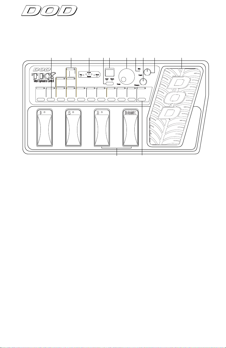
1) PROGRAM and BANK SELECTOR FOOTSWITCHES - These footswitches give you access to the User Programs in the TEC8 and allow you to
change User Banks.
2) EFFECT SELECTOR BUTTONS - This row of buttons lets you select an
effect group for editing, or to bypass the group completely. These
groups include Master Level, Reverb, Delay, Detune, Pitch Shift, Phase,
Tremolo, Ring Modulator, Pixellator, Chorus, Flange, Gate, EQ,
Distortion, and Compressor.
3) EFFECT GROUPS - The TEC8's effects are divided into 14 groups and
labeled on the front panel. When lit, the LED in each group indicates
that an effect in the group is active.
2
4) TUNER LEDS - These LEDs become active when the tuner is selected
and a note is played. Used in conjunction with the Program Display,
they will show whether the input note is sharp or flat.
5) STORE BUTTON - Stores your custom Programs in the User memor y
location you select.
6) DISPLAY - The LED display in Program mode, shows which Bank and
Program is currently selected. In Edit mode, it shows the number
and/or status of the selected effect. In Tuner mode, it displays the
input note.
7) DATA WHEEL - In Program mode, use the Data wheel to scroll through
Programs. In Edit mode, use it to change the setting of effect groups.
Page 5
Signal Processing
Signal Processing
8) CLIP LED - The red Clip LED lights when clipping occurs at the input of
the TEC8 or when the Master Level may be too high. To eliminate clipping, reduce the setting of the Input Level control or the Master Level
parameter until it only blinks occasionally with peak signals.
9) OUTPUT KNOB - Controls the overall output level of both the Left and
Right outputs and the Headphone output.
10) INPUT KNOB - Controls the level of the signal at the TEC8's input
stage.
11) EXPRESSION PEDAL - Controls the parameter selected by Expression
Assign Group. (See Expression Assign on page 8.)
12) EXPRESSION ASSIGN. - Expression Assign selects which effect para-
meter is controlled by the Expression Pedal.
Manufactured in the USA by
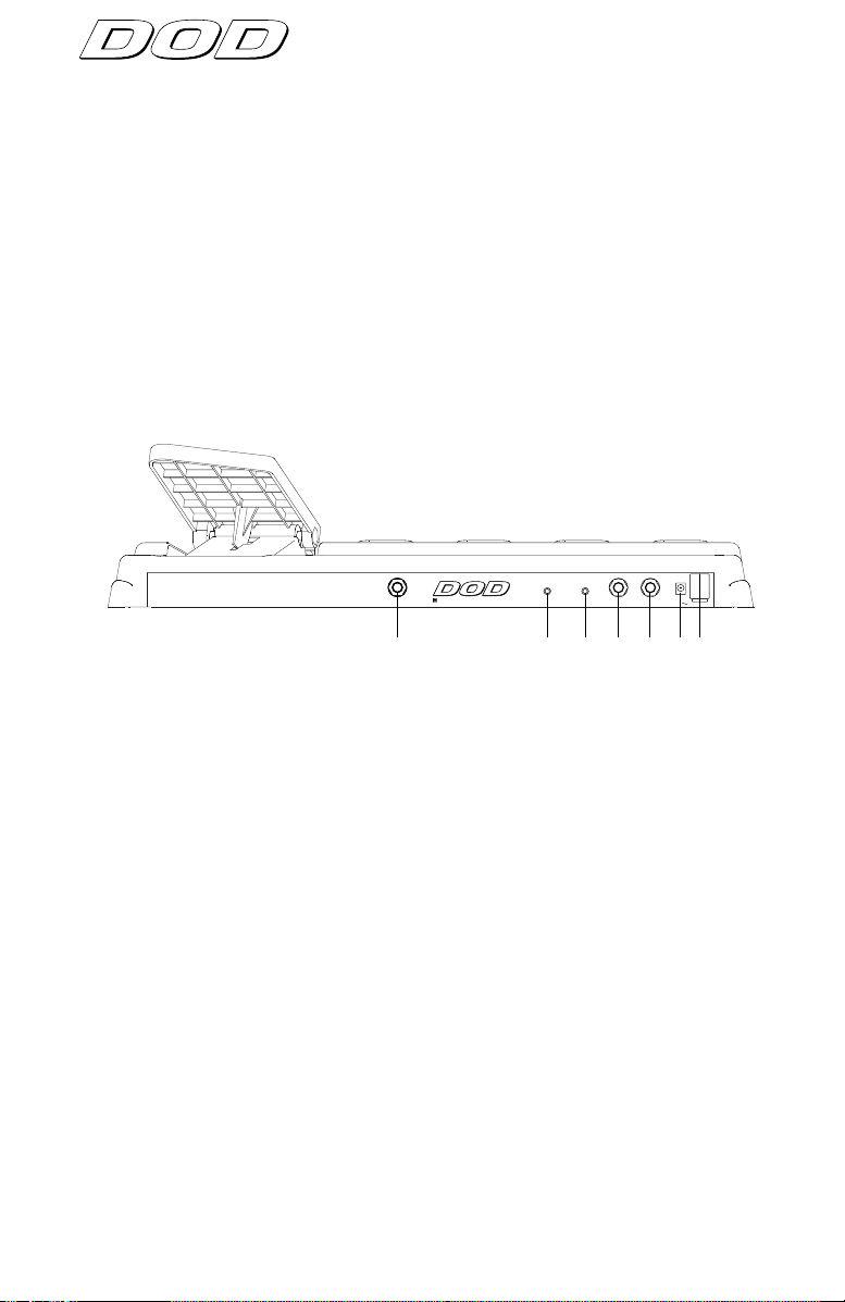
INPUT
A Harman International Company
HEADPHONE
JAM-A-LONG
LEFT / MONO OUT RIGHT OUT
POWER INPUT
9V 500ma
1234567
1) INSTRUMENT INPUT - Plug your instrument in here.
2) HEADPHONE OUTPUT - This stereo mini phone plug is for your head-
phones. The overall headphone level is controlled by the Output level
knob.
3) JAM-A-LONG™ INPUT - This stereo mini jack lets you connect your
tape deck or CD player headphone output to the TEC8 for personal jam
sessions. The Jam-a-Long™ signal is mixed with your instrument signal
at both the main and headphone outputs so you can play along with
your favorite tunes.
4) LEFT / MONO OUT - For stereo applications, this is the Left main out-
put. Use this jack for mono applications.
5) RIGHT OUT - For stereo applications, this is the Right main output. For
mono applications, leave this jack unconnected.
6) AC POWER ADAPTER INPUT - Connect the supplied PS750 AC power
adapter to this jack. Use only the adapter supplied with the TEC8. Use
of any other adapter may damage the unit.
7) POWER CORD STRAIN RELIEF - This clip prevents the AC power cord
from being accidentally pulled out.
3
Page 6

Signal Processing
Signal Processing
Signal Processing
Hooking Up and Supplying Power
DO NOT APPLY POWER TO THE TEC8 UNTIL INSTRUCTED.
1) STEREO: Connect the Left and Right outputs to a pair of guitar amplifiers, or the inputs of a mixing console. If you're using guitar amps, set
the tone controls flat (no boost or cut) and balance the levels between
them. If you're using a console, pan the TEC8 output channels hard
left and right, and turn down the high frequency EQ for best results.
MONO: Connect the Left output to a guitar amplifier or input of a mixing console.
2) Connect your instrument to the input of the TEC8.
3) Power up the TEC8 by connecting the supplied AC adapter between
the TEC8 and a power outlet.
4) Play your instrument and watch the Clip LED on the TEC8 carefully as
you set the Input knob. Turn up the Input level until the Clip LED
begins to light, and reduce the input level slightly. When the Input
knob is set properly, the Clip LED should only flicker on the loudest passages.
5) Set the Output level as desired.
The TEC8, like any piece of computer hardware, is sensitive to voltage
drops, spikes, and surges. Interference such as lightning or power
"brownouts" can seriously, and in extreme cases, permanently damage the
circuitry inside the unit. Here are a few tips that will help get the best possible performance out of your TEC8 while avoiding damage:
4
• Always make sure you have a "clean" power source for connecting to
the TEC8. This means that the AC power line you connect to the TEC8
should be as free from voltage fluctuations and RF interference as possible.
• Use a good quality spike / surge suppressor. This is an inexpensive
solution to all but the most severe AC line conditions. A good quality
power strip can save you a lot of money in repair bills because they
prevent large spikes and surges from reaching your equipment.
• Always make sure that your audio lines are as far as possible from
power cables. This will further prevent noise, hum, and stray magnetic
fields from entering your signal path. If audio and power lines must
run close to each other, try to avoid running them parallel to one
another
Page 7

Signal Processing
Signal Processing
SECTION 2 - PROGRAMMING THE TEC8
Navigating The TEC8
The TEC8 is designed to be both easy to program and flexible. The structure of a TEC8 Program is logical and doesn't require a lot of time to master.
Selecting Programs in the TEC8:
After you power up, use the Data wheel to scroll through the Programs.
DATA
As you scroll, the effect group and footswitch LEDs turn on and off. These
LEDs indicate which effects are used in each Program, and which Program
in the Bank is selected.
There are 14 effect groupings printed on the front panel of the TEC8.
Seven are digital effect groups (delay, reverb, etc.) , six cover the preamp
section (compression, distortion, gate, EQ), and one is the Expression
Assign group. Each group has its own LED that indicates the status of each
group.
If the Status LED is lit continuously, an effect in the indicated group is
active. If the LED is not lit, no effects in the group are active. If the LED is
flashing, edit mode is active, and effects in the group can be selected using
the Data wheel.
Directly below each vertical group are the Effect Selector buttons. These
buttons allow you to select and/or bypass effects in the TEC8. The following things happen when you use the Effect Selector buttons:
• When you select a bypassed effect, its group LED begins flashing and the
display shows two dashes (0 on EQs), indicating that the effect is selected but bypassed. (Pressing the Select button again activates the effect.)
• When you select an active effect, its group LED begins flashing and the
display shows the number of the currently selected effect. (Pressing the
button again bypasses the effect.)
User LED Indicator
The User LED below the display indicates that the current Program is a
User Program in the User bank when lit. When the LED is not lit, the current Program is a permanent Factory Program in the Factory bank.
Using The Footswitches
The TEC8's pedalboard consists of four footswitches. The far right
footswitch is the Bank selector, and the remaining three are Program selectors.
A Bank is a group of three Programs. There are 10 User Banks in the TEC8,
each with 3 Programs for a total of 30 User Programs. There are also 30
Factory Programs that can be selected using the Data wheel only. User
Programs in any of the Banks can be recalled in one of two ways:
5
Page 8

Signal Processing
Signal Processing
Signal Processing
1) by pressing the Bank select footswitch followed by footswitch 1, 2, or 3.
2) by turning the Data wheel in Program mode.
To Select Programs using the footswitches:
1) After you power up, the TEC8 defaults to Program mode. Select a Bank
by pressing the Bank selector footswitch. The display shows the selected bank number on the left side of the display and a dash on the right.
The display might look something like this:
2_
1
or 2) Press footswitch 1, 2, or 3. The dash in the display
2
NOTE: If a new Program number is not selected within 5 seconds after
pressing the Bank select button, the display returns to its previous setting.
3
Editing Programs
As you become more familiar with the TEC8, you may find that you need
to modify certain Programs to better fit your needs. Fortunately, the TEC8
is flexible enough to give you everything you need without being difficult
to program.
The following procedure is an example of how to modify your
Programs. Suppose that Program 63 (which has an Arena reverb,
250 ms Mono Delay, a Tremolo, Noise Gate, EQ, and
Compression) sounds close to what you want, but you want a
300 ms delay with low feedback instead. Here's how to change
it:
DATA
1) Use the Data wheel, or the Bank and Program selector
footswitches to select Program 63.
changes to show the number of the Program you
selected. The display might look something like this:
23
6
2) Press the Delay effect Group button. The Mono Delay Group
Status LED begins flashing and the display reads:
25
Page 9

Signal Processing
Signal Processing
Mono Delay
1-9 100ms
11-19 200ms
21-29 250ms
31-39 300ms
41-49 350ms
51-59 400ms
61-69 500ms
DATA
3) Look at the front panel Delay groupings to locate the effect
you want. In this case, you'll see that the 300 ms mono delays
can be found between 31 and 39 in the Mono Delay (not
Multi-Delay) effect Group.
4) Use the Data wheel to scroll until the the display reads:
NOTE: When you change the selected Parameter from the stored value, a
decimal point appears in the bottom right corner of the display and the
Store LED lights.
That's it! You can manipulate any effect setting in the TEC8 by pressing
the associated Effect Group selector button on the front panel and turning
the Data wheel. The Effect Group buttons also toggle the effects on and
off with each successive press of the button.
When you're editing Programs, be sure to pay attention to the flashing
Status LEDs. This helps you keep track of where you are in the menus.
IMPORTANT: If you want to store your custom Program so you can use it
later, follow the procedure on the next page.
Expression Pedal Assign
The TEC8 Expression Pedal can be assigned to control 1 of 10 different
parameters in a program. This adds a whole new dimension in your sound
by letting you make real-time effects changes during performance.
31.
Changing the pedal’s assignment is accomplished the same
as editing any other effect group in your program. Simply
Expression
1 Volume
2 Wah
3 Auto Wah
4 Mod Speed
5 Mod Depth
6 Mod Level
7 Detune
8 Pitch/Detune Level
9 Delay Level
10 Reverb Level
select the Expression Assign Group button and choose one
of the numbers that corresponds to the parameter you want
the pedal to control. In order for the Expression Pedal to
function with a parameter you have selected, a corresponding effect must be active within the program. To
turn on the Wah or Auto Wah, just select either one in the
Expression Assign Group.
The following list shows which effects are controlled by each Expression
Assignment.
Assignment
Pedal controls:
1- Volume: Master Volume.
2- Wah: Wah Wah.
7
Page 10

Signal Processing
Signal Processing
Signal Processing
Assignment Pedal controls:
3- Auto Wah: Auto Wah sensitivity.
4- Mod Speed: Chorus, Flange, Tremolo, Phaser, or Ring Modulator
speed.
5- Mod Depth: Chorus, Flange, Tremolo, or Phaser depth.
6- Mod Level: Chorus, Flange, Phaser, or Pixellator level.
7- Detune Detune amount.
8- Pitch/Detune Pitch Shift and Detune level.
Level
9- Delay Level: Mono or Multi Delay level.
10- Reverb Level: Reverb level.
When programs where Volume, Wah, or Auto Wah are selected in Expression
Assign, the sound will reflect where the current pedal position is,.otherwise the
pedal must be moved in order for the effect to be changed.
Storing Programs
After you have made modifications to a program, you may want to store
the changes. The TEC8 lets you store up to 30 Programs in the User memory locations.
Remember, you have to store any changes in a User Program memory
location otherwise all your changes will be lost.
To store a Program into a memory location:
User Store
1) Press the Store button. The Store LED begins flashing and the
User LED lights (if not lit already).
DATA
User Store
Bypassing
8
2) Use the Data wheel to select the User location where you
want to store the Program.
3) Press the Store button again to store the Program in the
location you selected.
Note:
Changes made by the Expression Pedal cannot be stored.
The TEC8's bypass functions are very simple.
To Bypass individual effects:
1) From Program mode, decide which effect you want to bypass
and press its Select button twice. The display reads:
--.
Page 11

Press the effect Select button to toggle the effect in and out of
bypass mode.
REMEMBER: The decimal point indicates that the value shown in
the display is not the stored value.
To Bypass the selected Program:
1
1) Press the currently selected Program footswitch on the pedalboard. The footswitch's Status LED flashes and the display
reads:
This indicates that the current program is bypassed. The
Program selector footswitch toggles the TEC8 in and out of
bypass mode.
The TEC8's Effects
The TEC8’s library of effects is capable of handling virtually any musical situation. The following charts give you relevant information about each
module's settings. For example, Noise Gates, Detuners, and Pitch Shifters
are not shown because their Module names are relatively self explanatory
and are displayed on the front panel. The Fast Swell and Slow Swell Noise
Gates have attack times of 500 ms and 1000 ms respectively, which create
a volume pedal or bowing type effect.
Signal Processing
Signal Processing
bp
DISTORTION The TEC8 gives you 8 distortions to choose from, 4 of which
include Cabinet Emulation. Each distortion has 10 settings, giving
you plenty of selections when using either an amp or for going
direct into a mixer or recording device.
Name
IT 1-10 (1-10) IT (SpkrSim) 1-10 (41-50)
Grind 1-10 (11-20) Grind (SpkrSim) 1-10 (51-60)
Fuzz 1-10 (21-30) Fuzz (SpkrSim) 1-10 (61-70)
FuzzIT 1-10 (31-40) FuzzIT (SpkrSim) 1-10 (71-80)
EQUALIZER The TEC8 is equipped with a flexible 3-band graphic EQ capable of
Low EQ @ 150Hz
+/- 12dB +/- 12dB +/- 12dB
CHORUSES A chorus works by splitting the input signal into 2 paths. One path
Gain/(Setting) Name Gain/(Setting)
boosting or cutting each band by 12dB.
Mid EQ @ 1kHz High EQ @ 7kHz
remains unaffected while the other is delayed and the pitch is modulated slightly. Both are then mixed back together. Chorus is used to
create lush thickening effects or wild pitch modulation.
9
Page 12

Signal Processing
Signal Processing
Signal Processing
CHORUSES cont'd.
Name
Slow 1 - .10Hz/25 2 - .15Hz/25 3 - .10Hz/50 4 - .15Hz/50
Medium 5 - .25Hz/25 6 - .35Hz/25 7 - .25Hz/50 8 - .30Hz/50
Fast 9 - 2.0Hz/25 10- 3.5Hz/25 11- 2.0Hz/50 12- 3.5Hz/50
FLANGERS Flangers are like choruses with the exception that part of the effected
Speed/Level Speed/Level Speed/Level Speed/Level
signal is returned back to the input. This is known as feedback.
Settings with larger feedback settings will create more dramatic “jet
airplane” type effects.
Name
Slow 13- .10Hz/40 14- .15Hz/40 15- .15Hz/50 16- .20Hz/50
Medium 17- .30Hz/50 18- .35Hz/50 19- .40Hz/60 20- .40Hz/60
Fast 21- .70Hz/60 22- .80Hz/60 23- 1.0Hz/75 24- 1.0Hz/80
PHASERS Phasers, like Flangers,split the input signal into 2 paths. One path
Name
Slow 1 - .10Hz/60 2 - . 10Hz/70 3 - .15Hz/80 4 - .15Hz/80
Medium 5 - .25Hz/60 6 - .25Hz/70 7 - .45Hz/70 8 - .45Hz/80
Fast 9 - .90Hz/40 10- 1.0Hz/50 11- 1.5Hz/50 12- 2.0Hz/60
TREMOLO Tremolos modulate the level of the signal. This effect is has been found
RING MODULATOR The Ring Modulator produces mathematically related sounds
Speed/Fback Speed/Fback Speed/Fback Speed/Fback
remains unaffected while the other is modulated in and out of phase.
When this is combined with the original, part of this signal is returned
back to the input (feedback). Increased feedback settings can produce
very spacey sounds, reminiscent of late 60’s early 70’s music.
Speed/Fback Speed/Fback Speed/Fback Speed/Fback
in guitar amps for years and has recently become a popular effect
again. The TEC8 gives you 9 speeds ranging from 2.0 Hz - 9.0 Hz
rather than a harmonically related sounds. It is useful for atonal and
percussive-like effects.
Setting
22 80 26 750
23 160 27 1000
24 320 28 1300
25 500
Frequency Setting Frequency
.
PIXELLATOR The Pixellator takes the input signal and undersamples it to create a
raw digital version of the original. This effect is popular in industrial,
rap, and techno music.
Setting
29-31 10 33/67, 67/33, 100/0
32-34 20 33/67, 67/33, 100/0
35-37 30 33/67, 67/33, 100/0
38-40 Random 67/33
Pixellation Wet/Dry Mix
10
Page 13

Signal Processing
Signal Processing
MONO DELAYS
The Mono Delays are arranged in groups of 9. Each delay time has a feedback ratio
(number of repeats) and level associated with each number. Here is an example of
how each delay time works:
Each Mono Delay time has 9 selections. These selections consist
Mono Delay
1-9 100ms
11-19 200ms
21-29 250ms
31-39 300ms
41-49 350ms
51-59 400ms
61-69 500ms
of 3 different feedbacks (number of repeats) and 3 different levels. For example, a Mono 200ms number 15 would have a
200ms delay time, a feedback of 30%, and a level of 30.
Selection fb/lev fb/lev fb/lev
1-3 0%/15 0%/30 0%/50
4-6 30%/15 30%/30 30%/50
7-9 50%/15 50%/30 50%/50
MULTI DELAYS
The Pong and Tap Delays have 2 delay times. The Pong Delays bounce from left to
right at a regular interval while the Tap Delays bounce left to right in more of a
rhythmic way.
As with the Mono Delays, each Multi Delay time has 9 selections.
Multi Delay
1-9 Pong 100/200ms
11-19 Pong 150/300ms
21-29 Pong 200/400ms
31-39 Pong 250/500ms
41-49 Taps 100/300ms
51-59 Taps 200/300ms
61-69 Taps 300/400ms
71-79 Taps 400/500ms
These selections consist of 3 different feedbacks (number of
repeats) and 3 different levels. For example, a Tap 300/400ms
number 63 would have a Tap delay time of 300 and 400 ms, a
feedback of 0%, and a level of 50.
Selection fb/lev fb/lev fb/lev
1-3 0%/15 0%/30 0%/50
4-6 30%/15 30%/30 30%/50
7-9 50%/15 50%/30 50%/50
Tuner
The TEC8 is equipped with a flexible tuner for on the spot adjustments. There are 3
selectable tuning references as well, Standard, tuning, 1/2 step down tuning, and
Whole step down tuning.
To access the tuner: Press and hold the currently selected program’s
footswitch. The display will read tu. Play a note and the display will show
which note is selected. The tuner LED’s will begin to light. If the LEDs to
the left of the green In Tune LED are lit, the note shown in the display is
flat. If the LEDs to the right are lit, the note is sharp.
11
Page 14

Signal Processing
To change tuning reference: Press and hold the currently selected
program’s footswitch. The display will read tu. Turning the data wheel
will select one of 3 references, Standard or A, 1/2 step down or Ab, or
Whole step down or g tuning. Now guitars that are tuned a 1/2 or whole
step lower than standard will still read the normal letter of the selected
string in the display.
Factory Program Reset
Resetting the TEC8 will erase all User programs and restore them to their
original Factory settings. Remember, when resetting the TEC8, all previ-
ous User settings will be lost.
To reset the TEC8
1- With the power off, press and hold the Low EQ and Mid EQ effect
group buttons.
2- Connect the power while still hold the buttons down. The display will
read:
At this point, all User presets will now be restored to their original Factory
settings
rS
12
Page 15

Signal Processing
Signal Processing
Factory Program List
Following is a list of the factory Programs available in the TEC8. They are divided
into Banks with a suggested application for each sound. As always, don't be afraid
to experiment.
PROGRAM #
Cool Stuff
01-Surfin' Drenched Reverb
02-Elbow punk/metal
03-Funkenwankin
Alternative
11-Grunge
12-Big Fluff
13-Industrial Pixellator
Metal
21-Tallica
22-Clean Metal Chorus
23-Wah solo
Country
31-Chicken Pickin’
32-Slide Volume
33-Country Tremolo
PROGRAM #
More Rock
51-“Harmanized” lead
52-Combo Rhythm
53-Homogenized Rock Effects
Retro
61-Dead Phaser
62-Fuzz/IT
63-Tremolo Clean Delay
Reggae/Ska
71-Skank
72-Dr. Reggae
73-Heavy Brains
Sound Effects
81- Adult Video
82- Gonkulator-Ring Modulator
83- Autoswell string pad
Rock
41-British stack
42-Stack lead
43-Flange stack
Bass
91-Octabass(For Guitar)
92-Thick bass
93-Funky bass
13
Page 16

Manufacturer’s Name: DOD Electronics Corporation
DECLARATION OF CONFORMITY
Manufacturer’s Address: 8760 S. Sandy Parkway
declares that the product
Product Name: TEC8
Product Options: All (includes internal battery power and with a Class
conforms to the following product specifications:
Safety: EN 60065 (1993)
EMC: EN 55013: (1990)
Supplementary Information:
The product herewith complies with the requirements of the Low Voltage Directive 73/23/EEC and the EMC Directive
89/336/EEC as ammmended by directive 93/68/EEC.
DOD Electronics
President of DOD
8760 S. Sandy Parkway
Sandy, Utah 84070, USA
Effective: 12/15/96
European Contact: Your Local DOD Sales and Service Office or
International Sales Office
3 Overlook Drive #4
Amherst, New Hampshire 03031, USA
Tel (603) 672-4244
Fax (603) 672-4246
Sandy, Utah 84070, USA
II power adapter that conforms to the requirements of
EN60065, EN60742, or equivalent).
IEC63 (1987) with Amendments 1,2,3
EN 55020: (1991)
DOD Electronics Corporation
8760 South Sandy Parkway
Sandy, Utah, 84070
Telephone (801) 566-8800
FAX (801) 566-7005
International Distribution: 3 Overlook Drive, Unit 4
Amherst, New Hampshire 03031 U.S.A.
FAX (603) 672-4246
TEC8 is a registered trademark of DOD Electronics Corporation
Copyright © 1996
DOD Electronics Corporation
Printed In U.S.A. 10/96
Manufactured in the U.S.A.
TEC8 18-2179-A
OS V1.0
Harman Music Group Inc.
 Loading...