

Page 1
EXTRACTIVE GAS DETECTOR
OPERATION MANUAL
Model PS-7
For Administrators
• Operate this unit only after reading and fully understanding the content of this manual.
• This Operation Manual was written for administrator use. Instructions for the basic
operations of this unit are provided separately in the standard Operation Manual. Refer
to the Operation Manual when necessary.
740 McArdle Drive, Unit C – Crystal Lake, IL 60014
815-788-5200 Phone 815-788-5300 Fax www.dodtec.com
Page 2
Some of the settings on this unit (alarm settings, etc.) are password protected.
This Operation Manual explains the following items:
•
Passwords
•
Changing settings
1 Passwords
1-1 Password-protected Settings
• Span adjustment (Refer to 2-1 Span Adjustment)
•
21vol% adjustment (Refer to
•
The values of various settings (Refer to 2-3 Changing Setting Values)
•
The values of alarm settings (Refer to 2-4 Changing the Alarm Settings)
1-2 Releasing the Password Lock
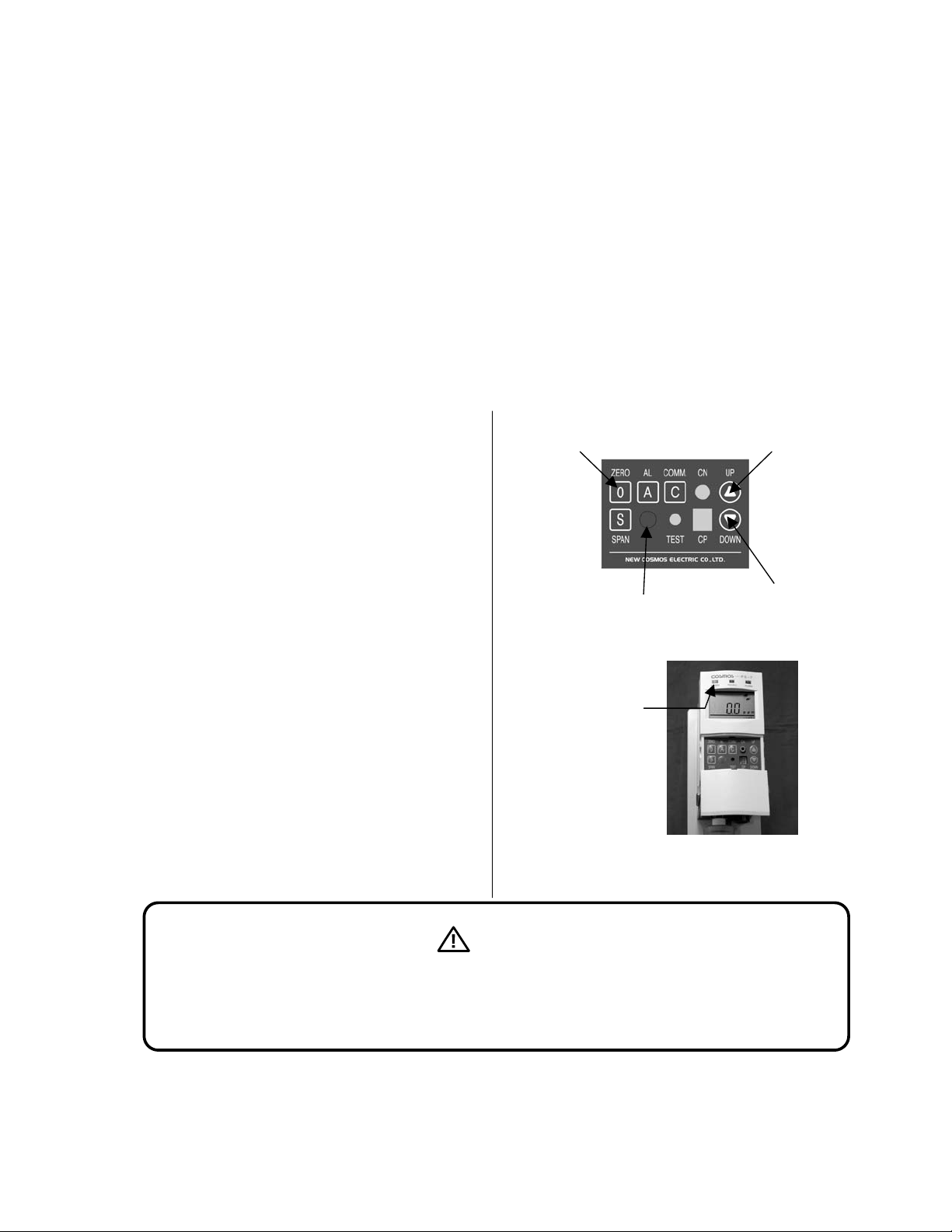
(1) Press these key switches in the following order.
1. ZERO switch
2. UP switch
3. Special command switch
4. DOWN switch
(2) The password lock is released when the
POWER lamp (green) blinks once.
2-2 21Vol% Adjustment
1
3
POWER lamp (green)
Blinks once
)
2
4
(3) The password lock is automatically reactivated
10 minutes after it has been released.
Important tasks, such as changing alarm settings, span adjustment, etc., can be carried out once
the password lock is released. Take the utmost care regarding confidentiality of the password.
Warning
Page 3
2 Changing Settings
g
2-1 Span Adjustment
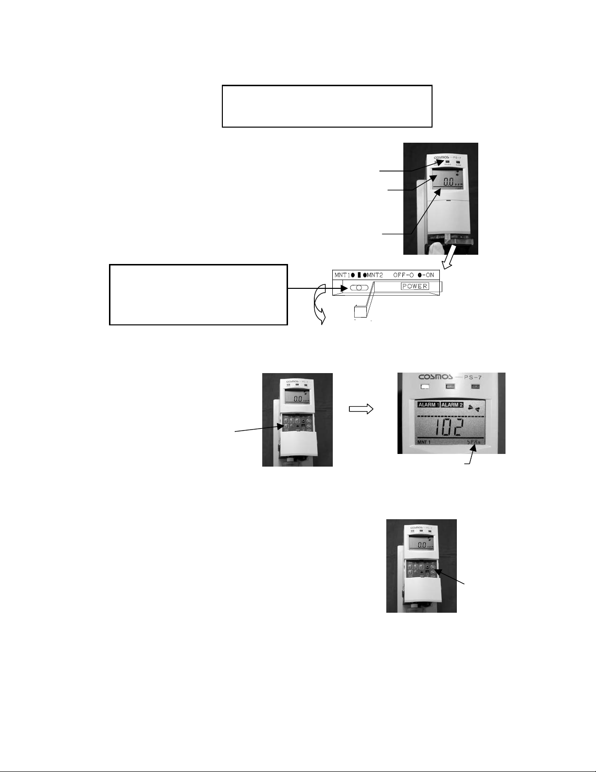
(1) Set to maintenance mode
(2) Release the password lock. (Refer to 1-2 Releasing the Password Lock.)
Left: Maintenance 1 (MNT1)
Center: Normal mode
Right: Maintenance 2 (MNT2)
Toxic gas sensor unit : CDS-7
Combustible gas sensor unit : CHS-7
(MNT1 or MNT2).
TROUBLE lamp (yellow) blinks.
The “__” indication and the
concentration value of the detected
as blink alternately.
MNT1 or MNT2 is displayed at the
bottom of the LCD screen.
Pull back to open
(3) Press the SPAN switch.
SPAN switch
(4) Let the calibration gas through.
SPAN is displayed at the bottom
right of the LCD screen.
(5) Use the UP/DOWN switch to adjust the concentration indication on the screen to that of the calibration
gas concentration.
(6) Once adjustments have been done, press the SPAN
switch again. The SPAN indication in the bottom right of the LCD
screen will go off, and the span adjustment will be completed.
UP/DOWN switch
(7) Remove the calibration gas, check that the detected gas concentration is under that of the alarm value,
and restore to the normal mode (by switching the maintenance switch to the center).
Page 4

2-2 21Vol% Adjustment
Oxygen sensor unit: COS-7
(1) Set to maintenance mode
(MNT1 or MNT2).
TROUBLE lamp(yellow)blinks.
The “__” indication and the concentration
value of the Oxygen blink alternately.
MNT1 or MNT2 is displayed at the
bottom of the LCD screen.
Left: Maintenance 1 (MNT1)
Center: Normal mode
Right: Maintenance 2 (MNT2)
Pull back to open
(2) Release the password lock. (Refer to 1-2 Releasing the Password Lock.)
(3) Press the SPAN switch.
SPAN switch
SPAN is displayed at bottom of the
LCD screen
(4) Let the calibration gas through.
(5) Use the UP/DOWN switch to adjust the concentration indication on the screen to that of the calibration
gas concentration.
(6) When the adjustment is completed, press the SPAN switch again. The SPAN indication in the bottom
right corner of the LCD screen will then disappear, and the 21vol% adjustment is complete.
(7) Remove the calibration gas and confirm that no alarm is displayed(
ALARM 1 , ALARM 2 is not shown). Then,
restore to the normal mode by switching the maintenance switch to the center.
Page 5

2-3 Changing Setting Values
Some of the setting values of the unit can be changed. Those that can be changed are listed in the table
below. The method for changing them is explained here.
(1) Release the password lock. (Refer to 1-2 Releasing the Password Lock.)
(2) Press the UP/DOWN switch (“U” or “V”)
until the setting you wish to
change ( “LCD Screen Indication” in the
table below ) is displayed at the bottom right of
the LCD display.
(3) Then press the special command switch, and the
setting to be changed ( “LCD Screen Indication”
in the table below ) and “—“ will flash alternately.
UP/DOWN switch
Setting to be changed
- - - - - d1 0
Special command switch
Page 6

(4) Change the value by using the UP/DOWN switches (“U” or “V”). When you are done, press the special
command switch again, and the alternating display in the bottom right corner of the LCD display will
become constant. The process is now finished.
LCD
Screen
The function
Indication
Each time the UP switch is pressed, it will move down the table to the next item.
d1 **
Time delay 1
d2 ** Time delay 2
az
as
zs *
Analog output
(base)
Analog output
(span)
Zero
suppression, or
21vol%
suppression
to be set
Remarks
Time delay (secs.) of the gas
alarm contact (1st level)
Time delay (secs.) of the gas
alarm contact (2nd level)
(*For our maintenance purposes only)
(*For our maintenance purposes only)
Displays the percentage of the full
scale value (rounded to the
percent)
1st: upper limit, 2nd : upper limit
H-H
L-L
When the DOWN switch is pressed, it will move up one.
H-L
Alarm mode
warning
1st : lower limit, 2nd : lower limit
warning
1st : upper limit, 2nd: lower limit
warning
Pyroletic
Con *
converter
0: Off 1: On
failure alarm
Calibration
CG **
gas
(*For our maintenance purposes only)
concentration
The existence
nEt *
F ***
FL ***
P ***
At *
×××
of a DeviceNet
unit
Display off
value
Displays rate
of flow
Sensor unit
output
Auto 21vol%
adjustment
0
: Non-existent 1: Existent
Calibration gas type in lower right of
LCD
f value in center of LCD
Shows the current rate of flow
(mL/min)
(*For our maintenance purposes)
0
: Off 1: On
Type of sensor unit (Normal display) (Depending on the sensor unit)
-- A t 1 0
Default value
To xi c :
CDS-7
Combustible
: CHS-7
Oxygen:
COS-7
Adjustable
Range
d1 0 d1 0 0 to 99 sec
d2 0 d2 0 0 to 99 sec
zs 5 zs 2 0 to 30%
H-H
H-H L-L
L-L
H-L
Con 0 Con 0 0 or 1
CG 40 CG 84
nEt 0 nEt 0 0
(Depending on the sensor unit)
(Depending on the rate of flow)
or 1
--
1
or
Page 7

2-4 Changing the Alarm Settings
A
A
The values of alarm settings on this unit can be changed. The method for changing them is explained
here.
(1) Release the password lock. (Refer to 1-2 Releasing the Password Lock.)
(2) Press the AL switch until the alarm setting
to be changed is displayed on the LCD display.
(The bottom right of the screen, as in the table below.)
The alarm setting for the actual gas concentration is
displayed in the middle of the screen, and the
percentage of the full scale value is displayed in the
bottom right corner
LCD Display
Indication
(Lower right)
A1 **
Tox i c : C D S-7
Comb. : CHS-7
Default value
A1 10
Oxygen: COS-7 A2 72
L switch
Explanation of
the default value
10% F.S.
72% F.S.
Gas concentration
The percentage of the full scale value
Adjustable
Range
0 to 100% F.S.
A2 **
Tox i c : C D S-7
Comb. : CHS-7
Oxygen: COS-7
A2 20
A2 76
20% F.S.
76% F.S.
0 to 100% F.S.
* Pressing the AL switch changes to 1st level Æ 2nd levelÆ Normal display.
* The A2 value should be greater than the A1 value in any case.
(3) Press the special command switch.
The setting to be changed and the “—“
indication will then flash alternately.
- - - - -
Special
command
switch
UP/DOWN switches
(4) Change the value by using the UP/DOWN key “U” and”V”.
When you are done, press the special command switch again, and the alternating display in the lower
right corner of the LCD display will become constant. The process is now finished.
1 10
(5) When this is finished, press the UP/DOWN switches (“U” or”V”) again to return to the normal display.
Note
The relationship between 1st level and 2nd level alarm values of each alarm mode is as follows:
Page 8

st
A
A
nd
A
A
nd
A
A
A
A
A
A
A
A
H – H mode (1
st
level: Upper limit, 2nd level: Upper limit)
Full Scale
0ppm
level gas alarm : ALARM 1 , ALARM 2 is displayed.
2
larm contacts ZA1 and ZA2 are activated
larm value is set by entering A2 **
st
level gas alarm : ALARM 1 is displayed.
1
larm contact ZA1 is activated
larm value is set by entering A1 **
L – L mode (1
st
level: Lower limit, 2nd level: Lower limit)
Normal state (No gas is detected)
Normal state
25vol%
21vol%
0 vol%
1
level alarm : ALARM 1 is displayed.
larm contact ZA1 is activated.
larm value is set by entering A2 **
2
level alarm : ALARM 1 , ALARM 2 is displayed.
larm contact ZA1 and ZA2 are activated.
larm value is set by entering A1 **
H – L mode (Upper limit, Lower limit)
Normal state
50vol%
21vol%
0 vol%
Upper alarm : ALARM 2 is displayed.
larm contact ZA2 is activated.
larm value is set by entering A2 **
Lower alarm : ALARM 1 is displayed.
larm contact ZA1 is activated.
larm value is set by entering A1 **
* A2 value should be always greater than A1 value.
Page 9

Manual Revision History
Edition No. Date Revisions
GAE-019 July 2004
Additional copies of this Operation Manual are available.
Contact the following address for ordering information.
Manufacturer:
New Cosmos Electric Co., Ltd.
2-5-4 Mitsuya-naka
Yodogawa-ku
Osaka 532-0036, Japan
Phone 81-6-6309-1505
Fax 81-6-6309-1514
Distributor:
DOD Technologies, Inc
740 McArdle Drive
Unit C
Crystal Lake, IL 60014
Phone 815-788-5200
Fax 815-788-5200
www.dodtec.com
 Loading...