

Page 1

C-8056SA
Metal Cutting
Band Sawing Machine
Version 20-8-2014
Utility Line
Instruction Manual
Page 2
Page 3

Page 4
2
PREFACE
Ever since it was established, SINGULAR MACHINERY has always followed the company's
policy of "Specialized Manufacturing, Customers First and Business Perpetuity". Oriented by
market demands, we have dedicated ourselves to technological innovation and produce the best
quality of hydraulic band saws to serve the industry. We always look forward to any advice given
by our customers.
We appreciate very much for your choosing Singular hydraulic band saws for your production.
To ensure correct operation and safety, the operator must thoroughly read the operation manual
before attempting to operate the machine.
Please fill in the basic information in the spaces below:
(1) MACHINE MODEL: ____________________
(2) SERIAL NUMBER: ____________________
(3) SHIPPING DATE: ____________________
(4) OTHERS: ____________________
C-8056SA
SAW BLADE
6800 × 54 × 1,6mm
MAIN DRIVE BELT
3V530X2
STEEL BRUSH BELT
M56
ITEMS
MODEL
Page 5

3
CONTENTS
1. SAFETY RULES ..................................................................... 6
2. MACHINE SPECIFICATIONS ................................................. 7
3. USER'S PREPARATION ........................................................ 9
4. MOVING AND INSTALLING THE MACHINE ....................... 11
5. OPERATION INSTRUCTIONS ............................................. 14
6. MACHINE REPAIR AND MAINTENANCE ........................... 20
7. TROUBLE SHOOTING ......................................................... 25
8. HYDRAULIC CIRCUIT DIAGRAM ........................................ 26
Page 6

4
1. SAFETY RULES
1.1 CLOTHING
To protect the operator from entangling or clamping by the machine, the operator must
remove gloves and beware of loose clothing. Before operating the machine, wear safety
shoes to avoid foot injury by waste material.
1.2 INSTALLATION
The machine must be properly grounded to avoid danger by electric shock. Use durable
insulating material to cover the power wires placed on the floor to avoid electric shock.
1.3 Be sure to tighten all guards before operating the machine.
1.4 While the machine is running, never try to touch the saw blade. Failure to comply may result
in accident by entangling.
1.5 During operation, if you need to check the interior of the machine, wait until the machine
has come to a complete stop before opening any guards.
1.6 Do not enter into the workpiece moving area. Lifting of the work pieces to the work piece
supporting is done by using an electric hoist, which is to be operated only by qualified
personnel.
1.7 Do not try to touch the circuit breaker, switches or buttons with wet hands.
1.8 Turn power off before maintaining or cleaning the machine.
1.9 Wear gloves for replacing saw blade, removing chips, replacing cutting fluid and moving
work pieces. Do not touch the teeth of the saw blade.
1.10 The coolant is not edible. If any should accidentally enter the mouth, spit it out immediately
and rinse mouth.
1.11 Do not operate the machine, maintain or check the machine under the influence of alcohol
or medication.
1.12 The machine will stop when safety guard is opened. While the machine is running, opening
the guard will cause the power to shut off but the running parts do not stop immediately and
can still cause danger. Be sure to open the safety guard only when the machine has come
to a complete stop.
1.13 Do not stand on the front or rear supporting rollers to avoid accident by slipping.
1.14 Be sure to perform a machine check before starting and check periodically. After the job is
finished, clean both the machine and the working area thoroughly.
1.15 The machine operator must be well trained. The training course takes one week, including
machine operation, workpiece lifting, saw blade replacement, and machine maintenance.
1.16 The machinery maintenance personnel must have knowledge of electric control and must
be well trained.
1.17 Do not apply the machine for cutting work pieces such as food, wood, plastic, poisonous
material, magnesium or magnesium alloy. This machine is designed for cutting steel bars
and profiled steel tubes only.
Page 7

5
2. MACHINE SPECIFICATIONS
2.1 SPECIFICATIONS
MODEL
C-8056SA
Cutting capacity
●
100 ~ 560 mm
100 (W) × 100 (H) to 300 (W) × 280 (H) mm
Bundle Cutting
Max.
560 (W) x 270 (H) mm
Min.
300 (W) x 120 (W) mm
Saw
Blade
Size
6.800 x 54 x 1,6 mm
Speed
16 to 85 m/min
Tension
Hydraulic
Motors
Output
Saw Blade
7,5 KW (10 HP)
Hydraulic Pump
2,2 KW (3 HP)
Coolant Pump
0,2 KW (1/4 HP)
Tanks
Hydraulic
130 L
Coolant
140 L
Working height
850 mm
Dimensions
3390 (W) × 2140 (H) × 1600 (L) mm
Net Weight
3800 kg
Page 8
6
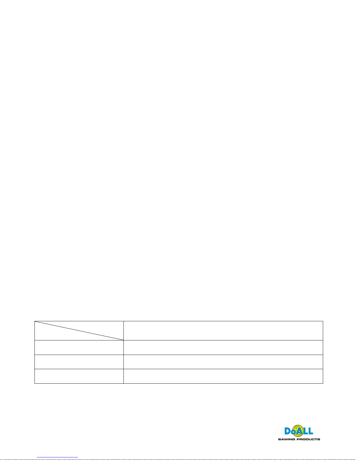
2.2 DIMENSIONAL DRAWINGS
2160
3220
3390
1600
DIMENSIONAL DRAWINGS OF THE C-8056SA
Page 9

7
3. USER'S PREPARATION
3.1 INSTALLATION SPACE REQUIRED
When installing the machine, the installation space should be considered as the figures shown
below:
1. Operator's working area
2. Workpiece collection area
3. Chip tank installation and maintenance area
4. Hydraulic unit checking area
INSTALLATION SPACE OF SH-8056SA
OPERTROR'S WORKING AREA
PARTS COLLECTION AREA
CHIP TANK INSTALLATION
AND MAINTENANCE AREA
CHECKING AREA
HYDRAULIC UNIT
600
4960
1600
1450
2500
Page 10

8
3.2 FOUNDATION REQUIRED
The thickness should be over 200mm. The foundation work must comply with local
regulations of construction. It is not suggested to install the machine in an upstairs area.
3.3 INSTALLATION ENVIRONMENT
※ Do not install the machine or controller at a location with direct sunlight and keep
the machine free from pollution of chips, water or oil from other machines.
※ The machine installation location should be free of vibration. Do not install the
machine in an area where there may be potential danger of explosion.
3.4 POWER SOURCE REQUIRED
Do not connect the machine to a power source with serious power interference caused
by welding machines or electric discharge machines. Keep the power source from
being affected by other machines. Avoid voltage drop resulting from insufficient power
capacity of the factory. Connect the machine to an independent power source.
C-8056 SA Input power: 12 KW
* Allowable input power tolerance: local voltage ±10%
3.5 GROUNDING
3.5.1 Do not use a grounding wire together with that of electric welding machines or electric
discharge machines.
3.5.2 Use a short and big grounding wire as possible.
3.5.3 Connect the grounding wire independently. Make sure the machine has been properly
grounded.
Page 11

9
4. MOVING AND INSTALLING THE MACHINE
4.1 MOVING THE MACHINE
The machine and roller stand are moved separately as shown in the figure below:
F
HOIST CAPACITY
The figure shows the lifting positions and steel wire rope is used.
5 T0N
C-8056SA
Page 12

10
F
FORKLIFT CAPACITY
The figure shows the machine being lifted by a forklift
C-8056SA
5 T0N
4.2 INSTALLING THE MACHINE
4.2.1 Once the machine has been moved to the worksite, you need to make the machine leveling
adjustment using the leveling adjustment bolts and pads. Use the bracket in front of the vise
as a reference plane for leveling adjustments. Leveling accuracy is shown as below:
(a) The front side of the machine should be about 0,2 / 100mm lower than the backside.
(b) The movable vise should be about 0,2 / 100mm higher than the fix vise.
4.2.2 Once the machine has been properly installed, you then need to install the roller stand at the
backside of the machine. The height of roller is the same as bed.
4.2.3 Then fix the machine and roller stand to avoid their unexpected shifting.
4.3 CONNECTING THE POWER WIRES
4.3.1 The machine is coated with rust-preventative oil before shipment. You are requested to
thoroughly remove all rust-preventative oil before using the machine to avoid damaging the
machine parts during operation.
CAUTION: Use a mild cleanser to remove rust-preventative oil. Do not use volatile solvents
to remove rust-preventative oil such as benzene and gasoline.
Page 13

11
4.3.2 REMOVING FIX OBJECTS
To avoid machine parts vibration during transportation, some objects are applied to keep the
machine parts fixed. Be sure to remove all these objects before connecting the power wires.
Otherwise, machine damage may occur once the power is turned on.
4.3.3 Before connecting power wires, make sure the machine voltage is in compliance with that of
your factory power source. The electric information of the machine is indicated on a name
plate attached to the front side of the machine.
4.3.4 Once the power wires have been connected, turn the power on and check if all motors run to
the correct directions.
4.3.5 PROPERLY MAKE GROUNDING WORK
Make sure the current supplied to PLC and frequency inverter are stable. Connect grounding
wire properly to prevent the control system from damage by instant current.
Page 14
12
5. OPERATION INSTRUCTIONS
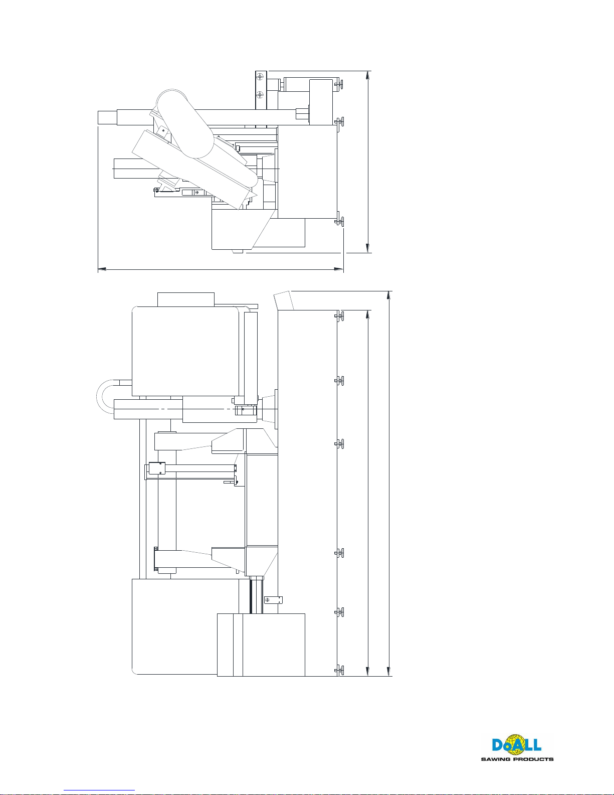
5.1 CONTROL PANEL
1 2 3 4
965
7 8 10 12
11
1. POWER LAMP
When the power switch is turned on, this power lamp lights up.
2. WORKING LIGHT SWITCH
Switch to right for turning on the light. Switch to left for turning off the light.
3. BED VISE RETRACTING SWITCH
Press the switch for retracting the table vise. When this switch released, the retracting
motion stops.
4. BED VISE FORWARD MOTION SWITCH
Press this switch for moving the bed forward. When this switch released, the forward
motion stops. The right indicating lamp lights up when vises clamping.
5. HYDRAULIC ON/OFF SWITCH
Press the upper switch for starting the hydraulic system. Press the lower switch for
stopping hydraulic system.
6. COOLANT SWITCH
Press this switch for turning on the cooling system. Press it again for turning off the cooling
system.
Page 15

13
7. EMERGENCY STOP SWITCH
When this switch is pressed, the control power is turned off.
8. BLADE START/STOP SWITCH
When the clamping indication lamp for the table lights up, press the upper switch for
starting the saw blade. Press the lower switch for stopping the saw blade.
9. SAW ARM RAISE SWITCH
Press this switch for raising saw arm. When this switch is released, the raising motion
stops.
10. SAW ARM LOWER SWITCH
Press this switch for lowering the saw arm. When this switch is released, the lowering
motion stops.
11. LIFTING ROLLER UPWARD/DOWNWARD SWITCH
Switch to right for roller upward and switch to left for roller downward.
12. SAW BOW STOP POSITION SWITCH
Switch to right: Saw head raises to the highest position and stops after the cutting
finished. Then the saw blade stops.
Switch to left: The saw blade stop without upward moving of saw head after the
cutting finished.
5.2 REPLACING AND ADJUSTING SAWBLADE
5.2.1 REPLACING SAWBLADE
(1) Press the "SAW ARM RAISE" key to raise the saw above the workpiece or the vise.
(2) Open the right and left wheel guards.
(3) Shift the tension lever to position, then the driven wheel will move toward the driving
wheel for loosening the blade tension.
(4) Loosen the screw that tightens the guide seats for loosening the tungsten plate.
(5) Remove the original blade.
CAUTION: Wear gloves for safety when removing the blade.
(6) Place the new blade on the two saw wheels. Twist the blade to place it between the tungsten
plate and auxiliary bearing of the guide seats and let the back of blade touches the upper
tungsten plate. Then, slightly tighten the screw of guide seats.
(7) Shift the tension lever to position to tighten the blade tension. Then return it to the
middle position.
Page 16

14
(8) Have the back side of the blade come into contact with the saw wheel edge.
(9) Shift the tension lever to position to tighten the blade tension.
(10) Adjust the steel brush position so that it just touches the gullet of blade tooth.
5.2.2 ADJUSTING SAW ARM POSITION
The saw arm position should be properly adjusted according to the workpiece width. Keep the
saw arm as close to the clamping position as possible. Make adjustments according to the
following procedures:
(1) Loosen the lock screw on the guide seats for loosening the tungsten plate. If it is clamped by
the hydraulic system, loosen it from the control panel.
(2) Loosen the fix handle on the left saw arm.
(3) Move the left saw arm to suitable position. A scale is attached on saw guide indicating the
work piece width.
(4) Tighten the fix handle on the left saw arm.
(5) Tighten the lock screw on the guide seats. If it is clamped by the hydraulic.
5.3 OPERATION INSTRUCTIONS:
(1) Select the correct saw blade according to the work piece type.
(2) Install the saw blade.
(3) Properly adjust the saw arm position according to the work piece width.
(4) PLACING THE WORKPIECE
a. Select a suitable speed of saw blade and adjust the position of belt on belt pulley.
b. Open the vise according to the work piece width.
c. Place the work piece on the roller stand.
d. Lower the saw arm until the saw blade is about 15mm above the work piece.
e. Move the work piece into the vise by using the lifting roller or manual. Then, set the
cutting length.
f. Press the "BED VISE CLAMPING SWITCH" to clamp the work piece until the
indication lamp at the right side lights up.
(5) Press the "BLADE START/STOP" switch. At this time the coolant system also starts
running. The coolant will flush out from the right and left tungsten plates and coolant nozzle.
You need to adjust the coolant flow properly.
(6) Adjust the blade speed according to actual cutting condition.
(7) Slowly turn the flow control valve and the pressure valve and check the cutting condition.
NOTE: When the job is finished, remove the work piece and clean the machine.
Page 17

15
5.4 NOTICES FOR OPERATION
(1) The "EMERGENCY STOP" should be used at a proper time. Except for an emergent damage
to the machine or operator occurs, normally stopping the machine by pressing the SAW ARM
RAISE SWITCH is suggested. During cutting, when the "EMERGENCY STOP" button is
pressed, the power will be shut off immediately. At this time, the hydraulic system still has
remaining power to feed the blade but no power on the blade which may result in breaking of
the blade teeth.
(2) Use proper flow and density of cutting fluid. Too much flow and density are not helpful for
cutting and cause environmental pollution.
(3) The blade speed adjustment can be identified by the cutting sound. A smooth cutting sound
means correct blade speed. A "rushed" or "impact" cutting sound means incorrect blade
speed.
(4) When using a new blade, it is suggested to reduce the blade speed and sawbow downward
speed to perform blade friction about 3-5 cuttings. Then, set at normal speed to ensure the
blade life.
5.5 CUTTING INFORMATION
5.5.1 SELECTING THE BLADE TEETH PER INCH
To ensure the economical, fast and accurate cutting, the blade teeth number and speed must be
properly selected according to work piece sizes and material.
A correct cutting rate must also be considered.
SAWBLADE SPECIFICATIONS
WIDTH
TEETH NUMBER
mm INCH
0.75/1.25
1.4/2
2/3
3/4
4/6
5/8
6/10
8/12
10/14
20×0,90 3/4× .035
* * * * *
27×0,90 1 × .035
* * * * * * *
34×1,10 11/4 × .042
* * * * *
*
41×1,30 11/2 × .050
* * * * *
*
54×1,30 2 × .050
*
* * *
*
54×1,60 2 × .062
*
* * *
*
67×1,60 25/8 × .062
*
* * *
80×1,60 3 × .062
*
* * *
SAWBLADE SPECIFICATIONS TABLE
Page 18

16
TYPE
TPI
SINGLE (SOLID)
BUNDLE
(SOLID)
SINGLE (PIPE)
BUNDLE (PIPE)
5/8
Thickness under
4 mm
Single thickness
under 4 mm
4/6
Under 80 mm
Thickness 4~10
mm
Single thickness 4~8
mm
3/4
60~150 mm
Single piece 20
mm
Thickness over
15 mm
Single thickness
8~15 mm
2/3
150~250 mm
Single piece 25
mm
Thickness over
25 mm
Single thickness over
15 mm
1.4/2
250~400 mm
0.75/1.25
400~1000 mm
SAWBLADE TEETH SELECTION TABLE
5.5.2 SELECTING BLADE SPEED AND CUTTING RATE
To ensure the machine and the blade fully extend their performance, the blade speed and cutting
rate must be selected properly according to the cutting material. The below table provides a
reference for selection.
Page 19

17
STEEL MATERIAL CUTTING DATA
CODE
DESCRIPTION
JIS
AISI
DIN
BLADE
SPEED
M/MIN
CUTTING
RATE
CM2/MIN
Low Carbon Steel
SS41
S10C
S15C
A570
1010
1015
St44-2
C10
C15
60~70
75~80
75~80
50~60
55~65
55~65
Mild Carbon Steel
S45C
S55C
1045
1055
C45
CK55
50~60
50~60
40~50
40~50
Cr Mo Steel
Nickel
Cr Mo Steel
Cr Mo Steel
Nickel
Cr Mo Steel
SCM440
SNCM8
SCM21
SNCM21
4140
4340
4118
8620
42CrMo4
34CrNiMo8
15CrMo5
21NiCrMo2
45~50
40~45
50~60
56~60
30~40
30~40
35~45
35~45
Tool Steel
Alloy Tool Steel
SK2
SKS3
W1
D1
C125W
105WCr6
30~45
30~35
30~35
25~30
Alloy Tool Steel
(15) Alloy Tool Steel
SKD1
SKD11
D3
D2
X210Cr12
X155CrVMo12
1
30~35
30~35
25~30
25~30
Alloy Tool Steel
SKD61
H13
X40CrMoV51
20~30
8~12
Stainless Steel
SUS304
SUS316
SUS430
304
316
430
X5CrNi1810
X5CrNiMo171
21
X6Cr17
35~40
25~30
30~35
25~30
15~20
20~25
Bearing Steel
SUJ2
52100
100Cr6
35~45
25~35
The above information is for reference only. Correct data should be dependent on the actual
cutting condition.
Page 20

18
6 MACHINE REPAIR AND MAINTENANCE
6.1 QUALIFICATION OF MACHINE PERSONNEL
MACHINE MAINTENANCE PERSONNEL: The person must have enough knowledge of
machinery and have been well trained.
ELECTRIC MAINTENANCE PERSONNEL: The person must have enough knowledge of
electronics and have been well trained.
6.2 MACHINE REPAIR
During operation, the machine may suffer from damage caused by personnel or other factors. In
case of any abnormal motion occurs, the operator needs to perform trouble shooting. If the
problem cannot be corrected, contact an experienced service technician for trouble shooting
assistance.
※CAUTION: Except for experienced maintenance personnel, do not dismantle any parts of the
machine without authorization to do so.
6.3 MACHINE MAINTENANCE
The machine must be operated under normal conditions and maintained periodically to upgrade its
performance and life.
The table below gives instructions for routine checks of the machine.
ROUTINE CHECK ITEMS FOR THE MACHINE
CHECK CYCLE
CHECK ITEMS
DAILY
1. Pressure gauge on hydraulic systems.
2. Coolant amount.
3. Steel brush condition.
4. Check if the saw blade is properly located on the right and left saw
wheel and between the front and rear tungsten plates.
WEEKLY
1. Check oil amount in hydraulic power unit.
2. Check lubrication oil amount in gearbox.
3. Shoot grease to the parts below:
※Tension slide ※Driven wheel ※Gear box base
4. Remove deposited chips under the chip collection tank.
Page 21

19
EVERY THREE MONTHS
1. Replace the oil in spindle gearbox.
(Replace oil after initial 3 months, then, every 6 months)
※Suggested gear oil: SAE 90 (ISO 220)
2. Check all lock screws. Tighten them if necessary.
3. Check main drive belt tension.
4. Check steel brush belt tension.
YEARLY
Replace oil in hydraulic oil tank.
(Suggested hydraulic oil: ISO-VG grade No.32)
6.3.1 CHANGE OIL IN GEARBOX
Remove the plug at the bottom of the oil tank. Place a container under the gearbox for collecting
the used oil. Wrap tape seal around the plug then tighten it securely. Fill oil through the oil inlet
port located at the top of the gearbox until the oil amount is over the red line on the oil level gauge.
6.3.2 CHANGE HYDRAULIC OIL
Remove the plug. Use a container for collecting the used oil. Wrap tape seal around the plug, then
tighten it securely. Fill oil through the oil tank until the oil amount is over the red line of the oil level
gauge.
Page 22

20
6.4 LUBRICATION
GREASE
NIPPLE
TENSIONING UNIT
Page 23

21
GREASE
NIPPLE
DRIVEN WHEEL
GREASE
NIPPLE
SIDE GUARD OF GEAR BOX
Page 24

22
GREASE
NIPPLE
WORM BEARING IN GEARBOX
Page 25

23
7. MACHINE TROUBLE SHOOTING
During operation, the machine may fail in operation due to personal or other factors. At this time,
the trouble must be solved as shown below:
SA Series
No.
ERROR MESSAGE
CORRECTION
1
Hydraulic system does not start
1. Release the EMERGENCY STOP
2. Check if the electric overload
2
Saw blade does not start
1. Check if the clamping indicating lamp
lights on.
2. Check if blade stalling or breakage
3. Check the overload relay
4. Check the electrical line
3
Saw bow does not move upward
Check if the limit switch damaged
4
Saw bow does not move downward
1. Check if chip jam under the guide
holder
2. Check if the solenoid valve of lifting
cylinder damaged
5
Cutting fluid abnormal
1. Check the amount of coolant tank
2. Check if the line clogged
3. Check if the pump damaged
4. Check the electrical line
6
Vise does not move
1. Check connection of the line
2. Check if the solenoid valve damaged
7
Seriously noisy when cutting
1. Adjust touching situation of blade and
the wheel edge
2. Check if guide holder damaged
3. Check if the upper tungsten insert or
bearing damaged or improper
touching with the blade
4. Check if the bearing of driven wheel
damaged.
5. Check if the bearing in gear box
damaged or bad lubrication
Page 26

24
8. HYDRAULIC CIRCUIT DIAGRAM
70kg/cm
2
M
2.5
11A
CRD063
CPF063
TENSION
LIFT
UNIT
VISE
CHIP REMOVING
70kg/cm
2
M
CRD063
2B3
INSERT
CARBIDE
ROLLER
FREED
HYDRAULIC CIRCUIT DIAGEAM FOR SH-8056SA
2
100kg/cm
 Loading...