


Instruction Manual
2013-V3
Serial No: 572-04101 to
Band Sawing Machine
DAMAGE CLAIM PROCEDURES
VISIBLE DAMAGE AT THE TIME OF DELIVERY:
1.Note damage on carrier’s delivery receipt. Accept the shipment. It can be returned later if repairs are not possible in the field.
2.Request a “damage inspection” from the delivery carrier:
a.The carrier will send his own people or contract an independent agency to make the inspection.
b.The inspector will request a signature on the report and leave a copy.
c.The carrier “damage inspection” report is not final. If additional damage is found when repairs are started, contact the carrier for another inspection; or at least give them the details of the damage.
3.Do not move the equipment from the receiving area and keep all shipping materials until carrier “damage inspection” report is complete.
4.If possible, take photographs of the damage and keep them for your files. Photos could possibly prove a claim at a later time.
5.Keep a record of all expenses and be sure they are documented.
6.Repair damage in the field whenever possible. Carriers encourage this to keep expenses down.
7.You have nine (9) months to file a claim.
CONCEALED DAMAGE:
1.You have fourteen (14) days to report damage not noted at time of delivery.
a.Report damage as soon as possible. This makes it easier to prove that it did not happen at cosignee’s plant.
b.Inspect machine(s) carefully before moving from the receiving area. Again, if machine is not moved, it is easier to prove your case.
2.Request a “damage inspection” from the delivery carrier:
a.The carrier will send his own people or contract an independent agency to make the inspection.
b.The inspector will request a signature on the report and leave a copy.
c.The carrier “damage inspection” report is not final. If additional damage is found when repairs are started, contact the carrier for another inspection; or at least give them the details of the damage.
3.Do not move the equipment from the receiving area and keep all shipping materials until carrier “damage inspection” report is complete.
4.If possible, take photographs of the damage and keep them for your files. Photos could possibly prove a claim at a later time.
5.Keep a record of all expenses and be sure they are documented.
6.Repair damage in the field whenever possible. Carriers encourage this to keep expenses down.
7.You have nine (9) months to file a claim.

OPERATOR'S INSTRUCTION MANUAL
METAL CUTTING BAND SAW
MODEL |
FIRST SERIAL NO. |
LAST SERIAL NO. |
2013-V3 |
572-04101 |
|
For your information and future reference, pertinent data concerning your machine should be written in the spaces provided above. This information is stamped on a plate attached to your machine. Be sure to provide machine model and serial numbers with any correspondence or parts orders.
Specifications contained herein were in effect at the time this manual was approvedforprinting. TheDoALLCompany,whosepolicyisoneofcontinuous improvement, reserves the right, however, to change specifications or design at any time without notice and without incurring obligations.
PLEASE READ THIS MANUAL CAREFULLY BEFORE OPERATING THE MACHINE! For Sales, Parts and Service, call 1-888-362-5572
DoALL SAWING PRODUCTS
2375B TOUHY AVENUE
ELK GROVE, ILLINOIS 60007 U.S.A.
The following registered trademarks of the DoALL Company are used in this manual: DoALL and Imperial Bi-Metal.
PRINTED IN U.S.A. |
PB-509.3 (9-09) |
|
|

TABLE OF CONTENTS
MACHINE DIMENSIONS |
|
Floor Plan ................................................................ |
1 |
Front View ............................................................... |
2 |
MACHINE FEATURES |
|
Front View ............................................................... |
3 |
INSTALLATION |
|
Location ................................................................... |
4 |
OSHA Notice ........................................................... |
4 |
Cleaning .................................................................. |
4 |
Unpacking ............................................................... |
4 |
Lifting ....................................................................... |
4 |
Machine Alignment .................................................. |
4-5 |
Electrical Installation ............................................... |
5 |
Preparation for Use ................................................. |
5 |
OPERATION |
|
Safety Precautions .................................................. |
6 |
Using the Job Selector ............................................ |
6 |
Electrical Controls ................................................... |
7 |
Band Speed Controls .............................................. |
7 |
Saw Band Preparation ............................................ |
7-9 |
Post Adjustment ...................................................... |
9 |
Worktable and Tilt Adjustment ................................. |
9-10 |
Wheel Brush and Chip Removal ............................. |
10 |
Typical Operation Procedures ................................. |
10-11 |
LUBRICATION |
|
Lubrication Chart ..................................................... |
12 |
Lubrication Diagram ................................................ |
13 |
MAINTENANCE |
|
Replacing Crowned Bandwheel Tires ..................... |
14 |
Insert-Type Saw Guides .......................................... |
14 |
Electric Motors ........................................................ |
14 |
Head Components .................................................. |
14 |
Transmission ........................................................... |
14 |
Wheel Brush ............................................................ |
14 |
Machine Cleaning ................................................... |
14 |
Band Drive Belt ....................................................... |
14-15 |
Mist Coolant ............................................................ |
15 |
TROUBLE SHOOTING ................................... |
16-17 |
ACCESSORIES |
|
Disc Cutter .............................................................. |
18 |
Miter No. 2 Cut-Off (Side Mount) ............................ |
18 |
Rip Fence ................................................................ |
18 |
Heavy Work Slides .................................................. |
18-19 |
Workholding Jaws ................................................... |
19 |
Air-Operated Power Feed ....................................... |
19 |
Chip Blower ............................................................. |
20 |
Mist Coolant ............................................................ |
20 |
Band Mist Lubricator ............................................... |
20 |
Worklight ................................................................. |
20 |
Magnifier ................................................................. |
20 |
Post Elevating Handwheel ...................................... |
20 |
Worktable Options ................................................... |
20-21 |
Air-Powered Worktable ........................................... |
21 |
Universal Calibrated Work Fixture .......................... |
21-22 |
Protractor Workstop and Alignment Gage ............... |
22 |
DBW-15 Buttwelder ................................................. |
22 |
Optional Saw Guide Blocks ..................................... |
23-24 |
90º Saw Guide Brackets ......................................... |
24 |
Adjustable Angle Saw Guides ................................. |
24 |
Dust Spout .............................................................. |
25 |
Band Filing .............................................................. |
25-26 |
Band Polishing ........................................................ |
26 |
Laser Line Generator Option ................................... |
26 |
How to read your serial number:
ii
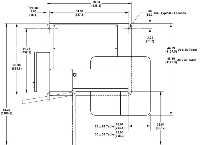
MACHINE DIMENSIONS
INCHES (± .03)
MILLIMETERS (± 1 mm)
FLOOR PLAN
MACHINE DIMENSIONS (Continued....) |
|
|
|
|
|
|
|
|
|
|
|
A |
Dimensions |
|
INCHES (± .03) |
|
B |
||
MILLIMETERS (± 1 mm) |
|
|
|
|
|
13" (330.2 mm) |
80.17" (2036.3 mm) |
||
|
|
|||
|
Work |
|
|
|
|
20" (508.0 mm) |
88.17" (2239.5 mm) |
||
|
Height |
|
|
|
|
24" (609.6 mm) |
91.17" (2315.7mm) |
||
|
|
|
|
|
|
|
30" (762.0 mm) |
97.17" (2467.7 mm) |
|
|
|
|
|
|
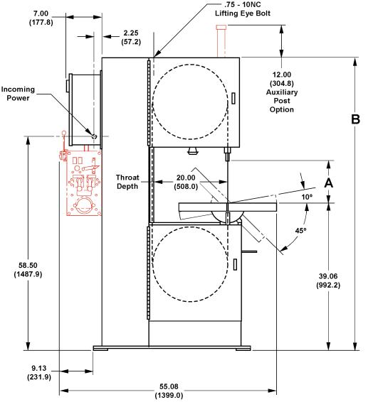
FRONT VIEW

MACHINE FEATURES
FRONT VIEW

INSTALLATION
All the “left”, “right”, “front” and “rear” designations in this manual are as viewed by the operator facing the machine controls on the electrical control box.
LOCATION
1.The floor area required by the standard machine is approximately 55 inches (1399.0 mm) in width by 44.5 inches (1130.3 mm) in length. Machine height for the standard machine is 80.17 inches (2036.3 mm). Refer to pages 1 & 2 for further machine dimensions.
2.Locate the machine to provide adequate space for your sawing needs. Be sure to provide sufficient clearance for: (a) Material loading and unloading; (b) All door openings; (c) Maintenance and lubrication procedures; (d) Operation of the any supplied machine accessories.
OSHA NOTICE!!
OSHA Regulation 1910.212 (5B).
Machinesdesigned for a fixed location shall be securely anchored to prevent walking or moving.
UNPACKING
1.The machine is fastened to and shipped on a wooden skid. Overseas shipments are also crated.
2.Carefully remove all protective covers, strapping, hold-down brackets, crating, etc. Then: (a) Remove all bolts which fasten the machine to the shipping skid; (b) Check inside the rear drive compartment for other removable brackets, extra machine parts or supplies which might have been placed there for shipment. (c) Inspect the machine and all parts for shipping damage. Claim procedures are listed on this manual’s inside front cover.
CLEANING
1.If necessary, use solvent to remove rust-preventive coating applied to exposed bare metal surfaces before shipment.
LIFTING
1.Atapped hole is located on top of the machine's saw head. Screw a forged 3/4-10NC eye-bolt into this hole for lifting purposes. Net weight of the machine is approximately 1250 pounds (567.0 kg).
DO NOT lift the machine by its sawing head.
MACHINE ALIGNMENT
To properly align the machine:
1.Placeshimsbetweenthefloorandthebasemounting pads until the machine is level with weight resting evenly on all the base pads.
Shim Locations.
2.Square the worktable to the side of the post by loosening the tilt lock bolt located in the machine's frame under the worktable and make the necessary adjustments. If necessary: (a) Position the worktable's tilt angle pointer at zero (0) on the tilt scale; (b) Tighten the tilt lock bolt.
Squaring Worktable to Post.

MACHINE ALIGNMENT (Continued....)
3.Place a good quality, 10 inch (254.0 mm) master square on the worktable against the post's back side. Measure clearance between the post and square near the bottom of the post. Clearance should be within 0.007-inch ±0.005-inch (0.18 mm ±0.13 mm) at the bottom of the post for standard machines.
4.Add or remove shims under the base pads until the correct post to square clearance is obtained.
The machine must be bolted to the floor for worktable loads over 100 pounds (45.4 kg).
ELECTRICAL INSTALLATION
Electrical installation must be made by authorized electrical maintenance personnel only!
1.Refer to the machine specifications plate on the machine frame to verify that the electrical supply circuit will meet the voltage/phase/frequency/ amperage requirements listed. A basic data plate is reproduced on this manual’s introductory page.
2.Bring the incoming power leads into the machine's electrical box. Refer to the electrical schematic, if necessary, when making the connections.
3.Turn the disconnect switch on the electrical box to ON. Then: (a) Alternately jog the Band Start and Stop pushbuttons; (b) Checktomakesurethesaw band is running in a clockwise motion: (c) Reverse the leads if saw band movement is incorrect.
PREPARATION FOR USE
1.Check the transmission oil level. Capacity is 1 quart (0.95 liters). If the reservoir level is low (or empty): (a) Check to see that the transmission plug is installed tightly; (b) See the "Maintenance" section for proper procedure of checking and/or filling the transmission. (c) RefertotheLubricationChartlater in this manual for recommended lubricants.
2.Shop air is required to operate the optional chip blower, mist coolant, sliding air table and/or band lubricator. Incoming air supply should be between 80 and 90 psi (5.5 and 6.2 bar or 5.6 and 6.3 kg/ cm²).
DO NOT exceed 90 psi (6.2 bar or 6.3 kg/ cm²).
3.Check the band mist lubricator unit (if supplied) for the proper reservoir level. Refer to the manufacturer supplied literature for reservoir capacity and recommended procedures.
4.Make sure all other points listed by the Lubrication
Chart have been properly serviced.
 Loading...