


Instruction Manual
400S
Serial No: 597-10101 to
Band Sawing Machine
DAMAGE CLAIM PROCEDURES
VISIBLE DAMAGE AT THE TIME OF DELIVERY:
1.Note damage on carrier’s delivery receipt. Accept the shipment. It can be returned later if repairs are not possible in the field.
2.Request a “damage inspection” from the delivery carrier:
a.The carrier will send his own people or contract an independent agency to make the inspection.
b.The inspector will request a signature on the report and leave a copy.
c.The carrier “damage inspection” report is not final. If additional damage is found when repairs are started, contact the carrier for another inspection; or at least give them the details of the damage.
3.Do not move the equipment from the receiving area and keep all shipping materials until carrier “damage inspection” report is complete.
4.If possible, take photographs of the damage and keep them for your files. Photos could possibly prove a claim at a later time.
5.Keep a record of all expenses and be sure they are documented.
6.Repair damage in the field whenever possible. Carriers encourage this to keep expenses down.
7.You have nine (9) months to file a claim.
CONCEALED DAMAGE:
1.You have fourteen (14) days to report damage not noted at time of delivery.
a.Report damage as soon as possible. This makes it easier to prove that it did not happen at cosignee’s plant.
b.Inspect machine(s) carefully before moving from the receiving area. Again, if machine is not moved, it is easier to prove your case.
2.Request a “damage inspection” from the delivery carrier:
a.The carrier will send his own people or contract an independent agency to make the inspection.
b.The inspector will request a signature on the report and leave a copy.
c.The carrier “damage inspection” report is not final. If additional damage is found when repairs are started, contact the carrier for another inspection; or at least give them the details of the damage.
3.Do not move the equipment from the receiving area and keep all shipping materials until carrier “damage inspection” report is complete.
4.If possible, take photographs of the damage and keep them for your files. Photos could possibly prove a claim at a later time.
5.Keep a record of all expenses and be sure they are documented.
6.Repair damage in the field whenever possible. Carriers encourage this to keep expenses down.
7.You have nine (9) months to file a claim.

OPERATOR'S INSTRUCTION MANUAL
METAL CUTTING BAND SAW
MODEL |
FIRST SERIAL NO. |
LAST SERIAL NO. |
400S |
597-10101 |
|
For your information and future reference, pertinent data concerning your machine should be written in the spaces provided above. This information is printed on a label attached to your machine. Be sure to provide machine model and serial numbers with any correspondence or parts orders.
Specifications contained herein were in effect at the time this manual was approved for printing. The DoALLCompany, whose policy is one of continuous improvement, reserves the right, however, to change specifications or design at any time without notice and without incurring obligations.
PLEASE READ THIS MANUAL CAREFULLY BEFORE OPERATING THE MACHINE! For Sales, Parts and Service, call 1-888-362-5572
For general information, visit our web site at: www.doallsawing.com
DoALL SAWING PRODUCTS
2375B TOUHY AVENUE
ELK GROVE, ILLINOIS 60007 U.S.A.
The following registered trademarks of the DoALL Company are used in this manual: DoALL, Imperial Bi-Metal, Kleen-Kool, and Tensigage.
PRINTED IN U.S.A. |
PB-543.3 (3-14) |
|
i |

TABLE OF CONTENTS
MACHINE DIMENSIONS |
|
Floor Plan .................................................... |
1 |
Front and Side Views .............................................. |
2 |
Top View .................................................................. |
3 |
MACHINE FEATURES |
|
Front View .................................................... |
4 |
Rear View ................................................................ |
5 |
INSTALLATION |
|
Location ................................................................... |
6 |
Unpacking ............................................................... |
6 |
Cleaning .................................................................. |
6 |
Lifting ....................................................................... |
6 |
OSHA Notice!! ......................................................... |
6 |
Floor Installation and Alignment .............................. |
6-7 |
Electrical Installation ............................................... |
7 |
Plant Air Installation (If Needed) .............................. |
7 |
Preparation for Use ................................................. |
7 |
OPERATION |
|
Safety Precautions .................................................. |
8 |
Using the Saw Band Selector ................................. |
8 |
Cutting Capacity ...................................................... |
8 |
Machine Controls .................................................... |
9-10 |
Saw Band Preparation ............................................ |
10-11 |
Band Speed Adjustment .......................................... |
11 |
Saw Guide Arm Adjustment .................................... |
12 |
Feed Rate Adjustment ............................................. |
12 |
Vise Jaw Adjustment ............................................... |
12 |
Saw Head Positioning For Angle Cuts .................... |
12 |
Coolant Selection and Application ........................... |
12-13 |
Dry Cutting .............................................................. |
13 |
Band Brush and Chip Removal ............................... |
13-14 |
Typical Sawing Procedures ..................................... |
14 |
Full Cycle Sawing Operation ................................... |
14-15 |
LUBRICATION |
|
Lubrication Chart ..................................................... |
16 |
Lubrication Diagrams .............................................. |
17 |
MAINTENANCE |
|
Saw Guide Insert Replacement .............................. |
18 |
Drive Belt Removal or Replacement ....................... |
18 |
Band Tension Adjustment ........................................ |
18 |
Coolant System ....................................................... |
18-19 |
Chip Removal .......................................................... |
19 |
Replacing Vise Bed Wear Plates ............................ |
19 |
Bandwheels ............................................................. |
19 |
Head Feed Cylinder ................................................ |
19-20 |
Counterbalance Spring ........................................... |
20 |
Electric Motors ........................................................ |
20 |
Band Mist Lubricator ............................................... |
20 |
TROUBLE SHOOTING ................................... |
21-24 |
ACCESSORIES |
|
Roller Stock Conveyors ........................................... |
25 |
Vertical Guide Rollers .............................................. |
25 |
Pneumatic Head Lift ................................................ |
25-26 |
Pneumatic Vise ....................................................... |
26 |
Full Cycle Option ..................................................... |
26-27 |
Band Mist Lubricator ............................................... |
27 |
Flushing Hose ......................................................... |
27 |
Large Receiving Tray .............................................. |
27 |
Workstop ................................................................. |
27 |
Worklight ................................................................. |
27 |
Laser Line Generator .............................................. |
28 |
How to read your serial number:
ii

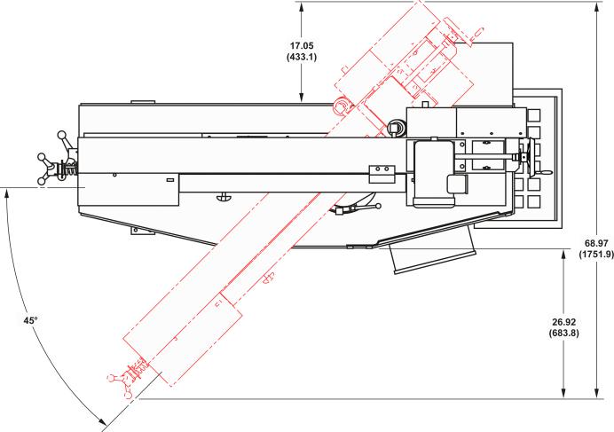
MACHINE DIMENSIONS
INCHES: ± .03 (MILLIMETERS: ± 1 mm)
FLOOR PLAN
1

MACHINE DIMENSIONS (Continued....)
INCHES: ± .03 (MILLIMETERS: ± 1 mm)
FRONT VIEW
SIDE VIEW
2
MACHINE DIMENSIONS (Continued....)
INCHES: ± .03 (MILLIMETERS: ± 1 mm)
TOP VIEW
3
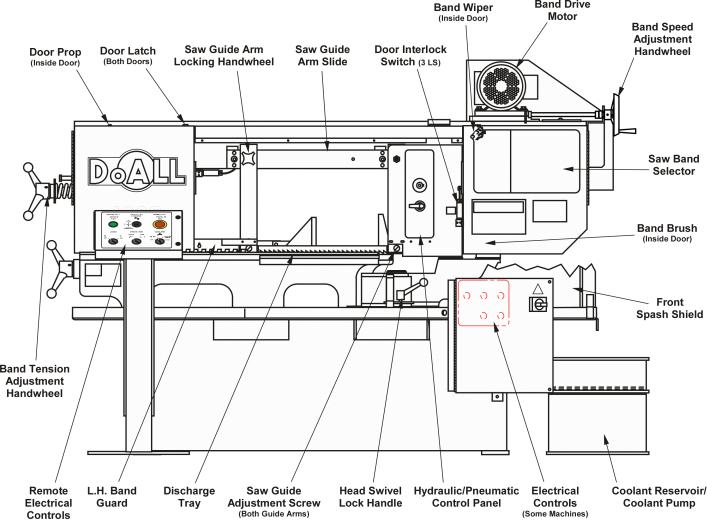
MACHINE FEATURES
FRONT VIEW
4
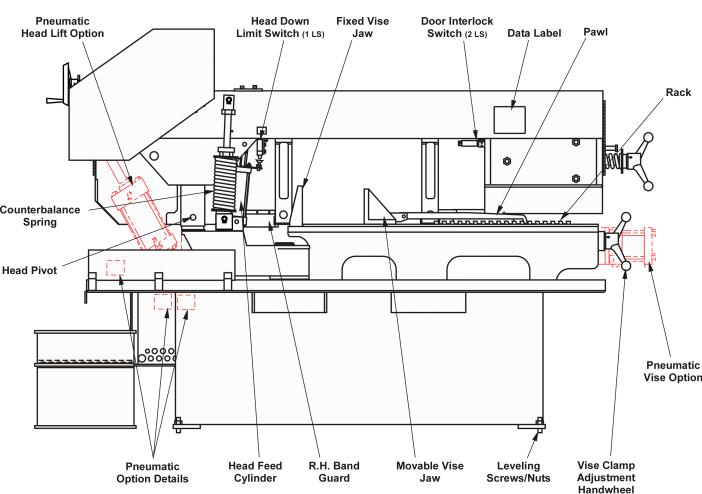
MACHINE FEATURES (Continued....)
REAR VIEW
5
INSTALLATION
All the "left", "right", "front", "rear" directions in this manual are as viewed by the operator when facing the control panel.
Inspect the machine for broken or damaged parts. Refer to this manual's inside front cover for damage claim procedures.
LOCATION
1.Plan the work area of the machine to allow adequate space for all your sawing needs with maximum convenience.
2.Locate the machine to provide sufficient clearance for: (a) Material loading and unloading; (b) All door openings; (c) Head elevation; (d) Head swivel;
(e)Maintenance and lubrication procedures; (f) Operation of any supplied machine accessories.
3.Approximate floor dimensions for the machine are shown on pages 1, 2 and 3.
4.Accessories such as roller stock conveyors will require additional working area.
UNPACKING
1.The machine plus other parts and supplies were fastened to a wooden skid before shipment.
DO NOT remove the the strapping holding the saw head to the base until the machine has been placed to its permanent location.
2.Remove all other protective covers, strapping, crating, etc. Then: (a) Remove wire if used to secure bandwheel doors; (b) Remove the screws attaching the machine to the shipping skid.
CLEANING
1.If necessary, use solvent to remove the rustpreventative coating applied to the machine's exposed bare metal surfaces before shipping.
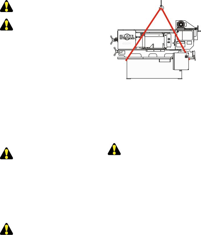
LIFTING
Never lift the machine by its sawing head.
1.Use a overhead hoist to lift the machine to its permanent location. Net weight is approximately 1100 pounds (521.6 kg).
Lifting the Machine.
2.Place the straps or chains under the coolant pan as shown. If chains are used, be sure to position padding where the chains makes contact with the machine frame to protect the finish.
3.Accessory roller stock conveyors can be lifted into position using a fork lift or other means that provides adequate safety precautions.
OSHA NOTICE!!
OSHA Regulation No. 1910.212 (5B).
Machines designed for a fixed location shall be securely anchored to prevent walking or moving.
FLOOR INSTALLATION AND ALIGNMENT
1.Remove the machine from its shipping skid.
2.While the machine is suspended in the air, thread the provided leveling screws (M16-2.0) into each machine base foot pad and attach the jam nuts. Slowly lower the saw into desired position.
3.Place a machinist's level on the vise bed. If the machine is not level, correct it by: (a) Adjusting the four (4) leveling screws in the base pads; (b)
Tighten the jam nuts. Machine must rest evenly on all pads.
4.Place coolant in the base pan and check its flow to the right side base opening. If the coolant does not flow as desired. Raise the leveling screws on the left side or lower the right side leveling screws in half a turn intervals until desired flow is acheived.
6
 Loading...