

Page 1
Segatrici
S.r.l
Instruction Manual
Segatrici S.r.l.
INSTRUCTION MANUAL
Pag.1
Edition A
Band Saw Machine
type
C-520 NC
Customer : DoALL Europa BV
March 1998
Page 2

Segatrici
S.r.l
Instruction Manual
INDEX
General warnings
1. General information.
2. Machine identification data.
3. How to use this instruction manual.
4. Manufacturer liability limits.
5. Type of use allowed.
6. Technical description.
7. Machine protections.
8. How to move the machine.
9. How to install the machine.
10. What to do to prepare the machine to operate.
11. Safety devices.
12. Machine use, calibration e tune-up.
13 How to dismantle the machine.
14. How to service the machine (ordinary problems).
15. Maintenance
16. Remaining dangers
17. Personnel training
18. Machine dismantle
19. Spare parts
Pag.2
Edition A
Exhibit
Spare parts A
Drawings B
Electrical schematic C
Hydraulic schematic D
Proof of test E
Declaration of Conformity F
Page 3
Segatrici
S.r.l
Instruction Manual
Pag.3
Edition A
GENERAL WARNINGS
This machine was design and built using the state of the art techniques, and with respect of the machine tools European
Laws.
Notwithstanding what above, it is implicit that working underestimating or forgiving the dangers which this kind of machine can generate, the operator could cause a serious injury to him/herself.
Therefore, the operator should carefully read the entire instruction manual, and respect strictly what in it prescribed.
In particular, please pay attention to the following suggestions :
1. Keep always your working area clean.
2. Avoid to keep in your working area pieces of material, chips, cans, or other things which could reduce the possibility of movement for the operator or even generate risks of injury.
3. Be always cautious using the machine, because, even if it is protected in every dangerous spot, it can be a dangerous equipment, and thus it has to be use being particularly careful and aware.
4. Give immediately notice to your supervisor if the machine needs to be maintained or serviced, even if the problem is caused by inexperience. An incorrect use of the machine can be dangerous and can cause injuries.
5. Do not try to repair the problem if you are not sure of what caused it.
6. Never service or maintain the machine when it is running. Always turn it off.
7. Never leave the machine working without respecting the safety rules or removing the safety devices.
8. Remove electrical power when the machine is not working.
9. Always wear protective cloths, especially when replacing the blade.
10. Never do anything imprudent.
11. Never touch the unprotected part of the blade.
12. Never cut any piece shorter than the shortest possible length.
13. Never start cutting if the material is not firmly clamped by the vises.
14. Move the material only if the cutting bridge is completely up.
Page 4

Segatrici
S.r.l
1. GENERAL INFORMATION
Instruction Manual
Pag.4
Edition A
1.1. G
OAL OF THIS MANUAL
This manual wants to explain instructions about how to operate safely, using texts, drawings, pictures and diagrams used by
themselves or combined to instruct the operator to use the machine.
1.2. R
EGULATIONS TO REFER
This manual was written to comply to the European Machine Directive UNI-EN 89/392 and following modifications, and
based on UNI-EN 292/1 e 292/2 concerning a safe use of the machine.
1.3. M
ANUAL DESCRIPTION
This document contains information needed to :
• install and make the machine work
• normal use of the saw
• how to maintain the machine
• how to service the machine
• how to dismantle the machine
.
.
Page 5
Segatrici
S.r.l
Instruction Manual
Pag.5
Edition A
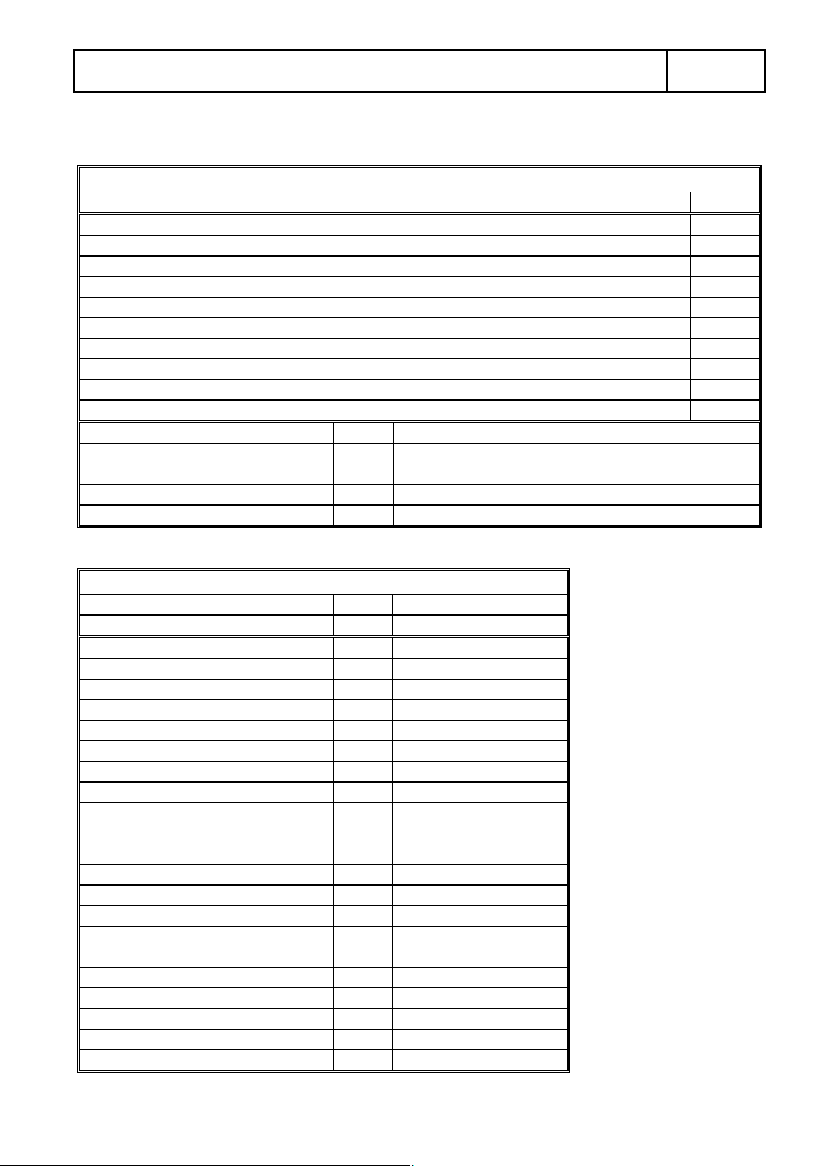
2. MACHINE IDENTIFICATION DATA
TAB 2.1
Identification data
Description
Name
Type C-520 NC Yes
Serial number 98043 Yes
Year 1998 Yes
Voltage and frequency 380 V 3f+N +- 10% 50 Hz +- 1% Yes
Hydraulic power unit Yes
Control circuit 110 V. c.a. 50 Hz
Dangerous area Area around the machine (1.5meters)
Working place Machine control panel
Type of tool Band saw blade
Description Band saw machine, type C-520 NC
Total amperage A 28
Maximum power kW 12.5
Approximate weight Kg 3500
Band Saw machine
Denomination or value
Machine
Plate
TAB 2.2
Technical Characteristics
Machine
Description C-520 NC
Round cutting capacity mm 520
Square cutting capacity mm 520x520
Index stroke mm 500
Band drive motor kW 7.5
Blade dimension mm 6400x54x1.6
Blade speed m/1’ 20-100
Hydraulic pump motor kW 4
Coolant pump motor kW 0.25
Hydraulic pump capacity l/1’ 27
Voltage of motors V 400 c.a.
Control circuit voltage V 110 c.a.
Cutting kerf mm 1.8
Hydraulic reservoir l 50
Coolant reservoir l 70
Working height mm 770
Machine overall dimension mm
Shipping dimension mm
Color RAL Green 6026
Moving components color RAL Orange 2004
Maximum noise level dB 80
Weight (Approximate) Kg 3500
2800x2500x2800 H
same
Page 6

Segatrici
S.r.l
Instruction Manual
Pag.6
Edition A
2.1 M
AIN COSTRUCTIVE CHARACTERISTICS
The machine uses :
• Cutting programmer CN015
• Trouble shutting control panel “Check Panel”
• Automatic feeding control device
• Blade speed controlled by an AC motor and a variable frequency drive.
• Working surface with non-wearable materials.
• Ball precision screws to control index movements.
• Vises with tempered inserts.
• Pressure reducer valves on vises.
• Self-positioning band guides.
• Carbide inserts mounted inside the band guides.
• Band brush powered by hydraulic motor.
• Chip conveyor powered by hydraulic motor.
• Cutting bridge mounted on chromate columns.
• Welded frame.
• Castings in gray iron C26
• Hydraulic band tension.
.
The saw is built to work in automatic also without an operator. A special design in the rear vise and working surface area allows the machine to cut slightly irregular bars.
2.2. B
LADE SPEED
The blade speed is controlled by an AC motor and a variable frequency drive, which allow to regulate the blade speed within
a range of 0- 100 m/1’. In this way the machine can cut both hard steels and aluminum. A digital reader constantly shows the
blade speed .
The blade speed can be adjusted :
• in automatic cycle during the editing ;
• in manual using a rotary potentiometer mounted on the control panel.
2.3. W
ORKING SURFACE
The material that has to be cut lays on a roller way that covers the entire stroke of the machine. The distance between the rollers is studied to avoid that short pieces can fall.
2.4. I
NDEXING
The material is fed by an index with hydraulic vises, which clamp the piece and move it under the blade. The index moves
on round chrome guides located underneath the roller table, and it is controlled by a tempered steel precision ball screw . The
index has two speeds : fast to move and slow to precisely position the piece. A rotary encoder (with a precision of a tenth of
a millimeter) controls the position of the index.
Page 7
Segatrici
S.r.l
2.5. V
ISES
The saw vises are hydraulic. The clamping part of them have a tempered insert bolted. Besides, the hydraulic circuit that
controls the vises has a pressure reducer valve with a gauge to avoid to clamp with too much strength the material and deform it.
Instruction Manual
Pag.7
Edition A
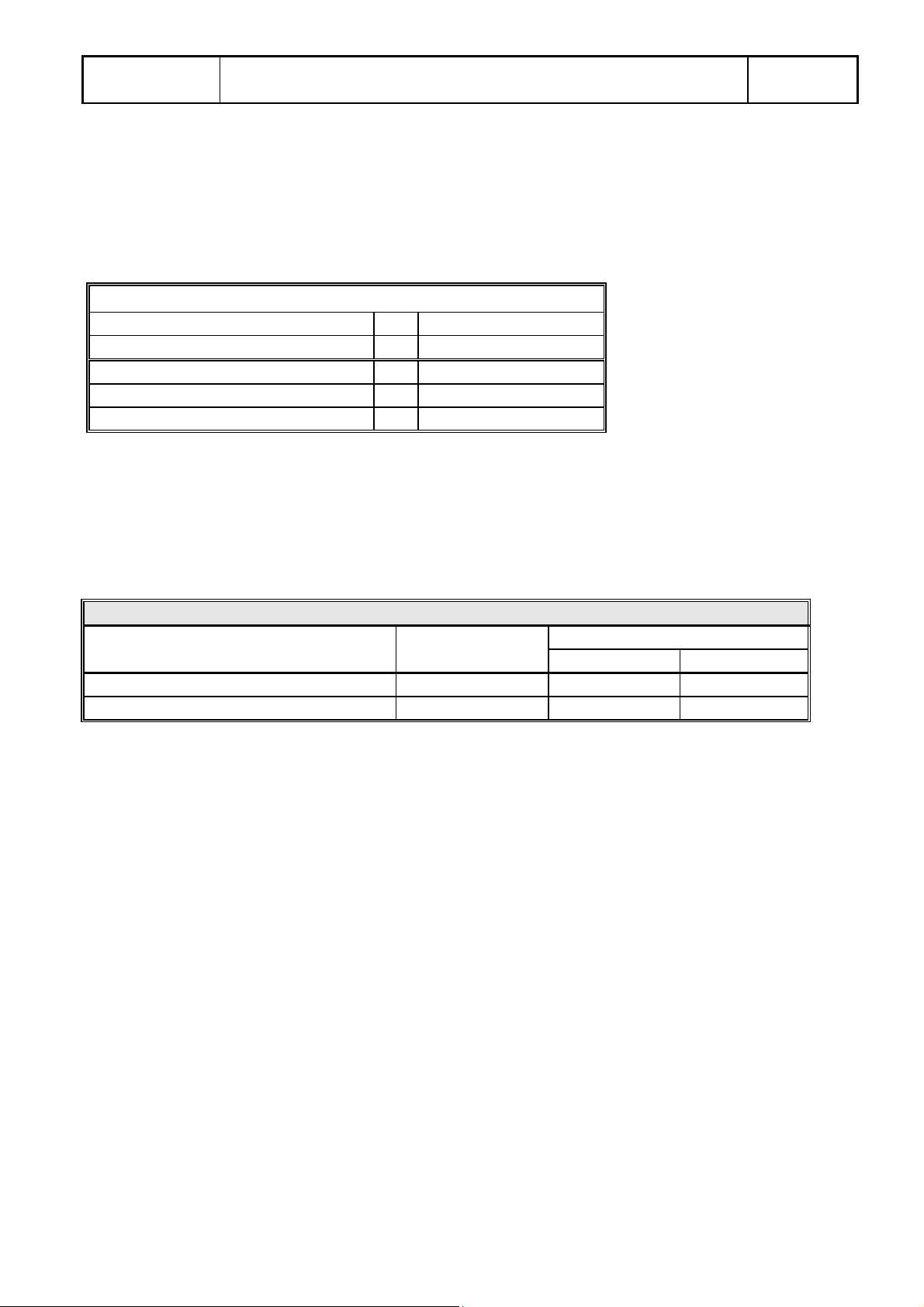
TAB 2.3
Cutting tolerances
Machine
Description C-520 NC
On the length mm
On the perpendicularity mm
±0,15 mm / 500 mm
±0,2 mm /100 mm
3. HOW TO USE THE INSTRUCTION MANUAL
3.1. W
HO SHOULD READ THE INSTRUCTION MANUAL
TAB 3.1 Who should read the manual
Description Operator Internal service
Instruction Manual Yes Yes No
Electrical Schematic No No Yes
The electrical schematic is included in this manual and cannot be supplied separately.
3.2. W
HERE TO KEEP THIS MANUAL
This manual, that is provided along the machine in one copy, should be kept where the machine is located, in a safe and protected place, to be consulted if necessary.
3.3. S
TRENGTH OF THIS MANUAL
1. This manual reflects the state of the art at the time the machine was built, and cannot be considered replaceable by a
newer version.
2. This manual has full force for all the life of the machine it goes along.
3. The customer is not allowed to copy totally or partially this manual to reach goals different than the one of the original manual, and to avoid that a partial documentation replaces the original one.
?
Mechanical Electrical
3.4. M
ANUAL UPDATE
The manufacturer does not have to update this manual if improvements are adopted on newer machines of the same kind of
the one this manual make reference to.
This manual will be updated by the manufacturer only if :
Page 8

Segatrici
S.r.l
• this manual contains mistakes, errors, or something is missing;
• the original machine is modified by the manufacturer.
Marginal errors or missing elements, if considered important for the correct work of the machine and its safe use will be immediately notified through an “Errata Corrige”.
To modify this manual the manufacturer will bring all the copy of the same edition back and then new copies will be sent to
the customer.
The latest version is marked with higher letter (A, B....). The first edition is called “Edition A”.
3.5. H
OW TO OBTAIN MORE COPIES
If necessary, the customer can obtain new copies of this manual simply making a written request and mentioning on it the
machine serial number.
If copies are requested, the manufacturer has the right to be paid to issue them.
Instruction Manual
Pag.8
Edition A
3.6. I
F THE MACHINE CHANGE OWNER
If the original customer sales the machine, he/she should notify the manufacturer that the machine changed ownership, so to
allow the manufacturer to inform the new user on the dangers and limits of liability.
3.7. S
UGGESTIONS
The customer should notify the manufacturer if improvements are necessary and where they are to increase an easy understanding of this manual/
4. LIABILITY LIMITS
The manufacturer cannot be responsible if the machine if used in one following ways , which are classified as inappropriate :
4.1 I
NAPPROPRIATE USE OF THE MACHINE
It has to be considered inappropriate the use of the machine if :
• the safety rules are partially are completely unattended ;
• what the manufacturer prescribed is not done ;
• the a danger or injury is due to an incorrect installation or assembly of the machine, and it was not done by the customer
or under his surveillance ;
• wrong installation of protective equipment after maintenance or service ;
• hydraulic or electrical problems due to the producer of the component and not to the producer of the machine ;
• big deficiency in maintenance ;
• modifications or maintenance on the machine without authorization of the manufacturer ;
• use of atypical tools, other than the ones suggested by the manufacturer ;
• use of non-original spare parts, other than the one suggested by the manufacturer ;
Page 9

Segatrici
S.r.l
• Partial or complete non-observance of the instructions ;
• machine used by uninstructed operators without control of an expert operator ;
• movement or machining of non-typical materials, or oversize and overweight materials compared to the ones indicated ;
• natural calamities, including earthquakes, floods or others which could provoke danger or faults to the machine or its
structures easy to be identified ;
• if electrical , pneumatic or mechanical safety features were partially or completely removed ;
• maintenance while the machine is working;
• when parts of the machine are tensioned using temporary connections, without protection or using faulty materials ;
• a person without experience is within the danger area while the machine is running ;
• a person with experience is within the danger area while the machine is running with the automatic cycle.
It has to be considered inappropriate also when the machine runs without enough surveillance to assure the operator
safety or to assure that the machine can run properly.
Instruction Manual
Pag.9
Edition A
Page 10

Segatrici
S.r.l
5. TYPE OF USE ALLOWED
Instruction Manual
Pag.10
Edition A
5.1.
MACHINE
This machine was design and built to comply a professional use, meaning that, besides the technical knowledge required, it is
necessary to have a specific knowledge to operate the saw to obtain the required goals.
5.2. O
PERATOR
The saw operator should have experience on similar type of machine. People with low or none experience must be educated,
followed and watched by a supervisor with enough experience and ability.
Therefore, the operator must be aware about dangers related to the use of this machine, and dangers due to normal handling
of metallic materials, similar, or heavy .
This machine cannot be used by people with handicaps or disables.
5.3. R
EGULATION
Designing and building this machine we respected the following laws and rules :
• UNI rules
• CEI rules
ADDRESSEE
and more in detail, concerning the safety features (type A and B rules):
• European Community Machine directive 89/392;
• CEI-EN 60204-1 and related rules concerning electric’s, with respect of EC directive 73/23 ;
• EN 292/1
• EN 292/2
If not clearly specified, every component used on this machine was UNI and CEI approved at the time it was bought or
made.
5.4 T
YPICAL USE
This machine was designed and built to cut metallic materials fed by automatic systems and with overall size non larger than
the ones listed in the chart below (5.4). The saw can move :
1. movement of the material before and after each cut ;
2. vertical movement of the cutting bridge ;
3. blade rotation.
All these movements could take place at the same time.
The saw has the following performance :
Page 11

Segatrici
S.r.l
Instruction Manual
Tab. 5.4
Characteristic MIN MAX
Cutting speed cmq/m 5 140
Material feeding speed Mt./m 30 300
Cutting bridge falling rate (w/o material) Mt./m 3 30
Bars size mm
∅ 10
Bar weight kg. 1.336 3.528
5.5. L
IMITS USING THE SAW
The machine has two limits of use due to :
• operator’s inexperience
• material size and weight
1. The operator’s experience is particularly necessary when the saw runs in manual cycle ;
2. material size and weight must be within the ones above shown.
(manual)
Pag.11
Edition A
∅ 520
5.6. W
ORKABLE MATERIALS
This machine can cut only metallic bars, pipes and tubing. Every other use will is considered inappropriate use of the machine.
5.7. W
ORK AREA
This machine has to work in industrial environment. It is design to make mechanical machining under human control, but
the operator presence is not required continuously.
It is recommended to keep clean and free of interference the area close to the machine.
This machine use a mixture of oil and water as coolant liquid. Thus, the working area could be slippery and dirty.
HIS AREA MUST BE MARKED BY AN APPROPRIATE SIGNAL
T
5.8. W
ORK PLACE
.
The machine has one work place in front of the control panel.
A second temporary work place is aside the vises, the register them, and to change the blade.
Each work place must be easy to reach when necessary, without interference, even temporary. The machine can work
automatically without operator, who must be present during the manual operations of loading and unloading, and control the
control panel operations.
Page 12

Segatrici
S.r.l
No specific illumination is required, but the work place must be well illuminated to respect the requirements set by present
safety rules.
Only authorized people and maintenance personnel should be allowed to reach the saw work place.
The operator must be equipped with personal protection instruments, like gloves and safety glasses.
Instruction Manual
Pag.12
Edition A
5.9. C
OMMAND MODES, STOP, EMERGENCY STOP AND OUT OF SERVICE
5.9.1 Command modes
The saw can be controlled in two different ways, turning or pressing a selector switch or a push-button (different ways for
different models). The switch enable a relay which insert the manual mode.
1. Automatic mode ; the switch is on the automatic mode. All automatic commands are enable.
2. Manual mode, the switch is on the manual mode. All the commands are switched to the control panel push-button and
switches.
5.9.1.1. Stop
The saw stops when the cutting cycle is over.
5.9.1.2. Emergency stop
The emergency stop stops the machine removing tension from the control circuit.
5.9.1.3. Out of service
The saw can be turned out of service removing tension from the control circuit, switching off the main disconnect switch
located on the front face of the enclosure. A signal saying “Out of service” must be placed on the machine, and it is operator’s duty to verify that the machine cannot generate danger situations.
.
5.9.1.4. Safety precautions
The machine cannot generate danger situation when it is completely without electric or hydraulic power.
Concerning the electrical power, the machine must be completely disconnected from electrical sources, turning of the
electrical socket on the building electrical panel. The machine cannot be considered completely safe if the only main disconnect switch of the machine is turned off.
Page 13

Segatrici
S.r.l
Instruction Manual
6. TECHNICAL DESCRIPTION
6.1. M
ACHINE STRUCTURE
This saw is manly made by :
1. Base frame
2. Cutting bridge
3. Hydraulic power unit
4. Control Panel
5. Coolant system
Pos. Tab 6.1. Base frame
6.1.1. Base frame
6.1.2. Chip conveyor
6.1.3. Indexing (Only for automatic machines)
6.1.4. Vises (Only for automatic machines)
Pag.13
Edition A
6.1.1. Base frame
The machine frame is welded and machined. The material used is Fe 37. In the weldment there are two reservoirs, one for
the coolant liquid, and the second for the hydraulic oil.
The frame is machined to avoid corners or abrasive points that could be dangerous. It is painted with two layers of paint, the
first of which prevent corrosion.
It is machined to be assembled with other machine components.
6.1.2. Chip conveyor
It is standard on automatic machines and optional on semi-automatic machines, and it is made by :
• Bended and welded frame with Fe37 steel.
• Hydraulically powered chip screw.
• Protective brackets.
• Chip tank
• Coolant reservoir
The chip conveyor removes chips coming from the band brush and from the cut, taking them outside the machine.
6.1.3. Indexing (Exhibit A03)
Used only for automatic machines, it includes :
• Index frame welded and machined , and made using Fe37 steel.
• Precision ball bearing screw, to move backward and forward the index frame.
• Steel vises to clamp the material, controlled by hydraulic cylinders.
Two limit switches are mounted on the index, the first to set the zero, and the second to control when the index is out of material.
Page 14

Segatrici
S.r.l
6.1.4. Vises (Exhibit A05)
It includes :
• clamping vises made with a gray iron casting G26, machined. Vises are controlled by hydraulic cylinders.
6.2. C
UTTING BRIDGE
Pos. Tab 6.2 Cutting bridge
6.2.1 Cutting bridge frame
6.2.2 Guiding columns
6.2.3 Columns connection
6.2.4 Lifting cylinder
6.2.5 Blade tension assembly
6.2.6 Blade drive assembly
6.2.7 Band brush assembly
6.2.8 Left and right band guide
6.2.9 Cutting servo-control
6.2.10 Wheels
6.2.11 Bland drive motor
Instruction Manual
Pag.14
Edition A
6.2.1 Cutting bridge frame
The cutting bridge frame is a steel Fe37 weldment ; it is machined to be assembled with other machine components.
The bridge was design and built to endure the cutting strength, keeping enough sturdiness.
The frame is mechanically machined and painted with anti-corrosion agents and with nitro paint.
The blade is completely protected where it does not work. Covering the wheels, there are two doors that can be opened to
change the blade. Two safety switches are mounted on these doors, so to stop the machine if the covers are not in position.
The blade rotates on the wheels, one of which is driven, and the other one is idler.
6.2.2 Guiding columns
The columns guide vertically the cutting bridge movement. They are made with chrome bars, hardened and grinded.
6.2.3 Columns connection
Made using a Fe52 steel square tube, the columns connection connects and makes the guiding columns sturdy. It is fastened
to the columns through two locknuts. The lifting cylinder is fastened to the center of the connection tube.
6.2.4 Lifting cylinder
This is an hydraulic cylinder, with chrome rod and lapped cylinder. The lifting cylinder is a double effect cylinder. The head is
fastened to the columns connection, and the final end of the rod is fastened to the cutting bridge using a locknut.
Page 15

Segatrici
S.r.l
6.2.5 Blade tension assembly
This assembly has to keep the blade at the right tension when the machine is running. There is a steel slide which support the
idler wheel shaft. An hydraulic cylinder, that works on the slide, keeps the band in tension. A limit switch protects the machine turning immediately off the machine if the blade brakes.
6.2.6 Band drive assembly
The band is powered by an AC motor which automatically regulates the rotation speed. Using two pulleys and three V-belts,
the motor makes the speed reducer turning. On the other end of the reducer there is the drive wheel, that is fastened to the reducer using a collet locking.
6.2.7 Band brush assembly
A band brush is powered by an hydraulic motor, and it cleans the teeth removing the chips.
6.2.8 Left and right band guides.
The band guides have to :
Instruction Manual
Pag.15
Edition A
• straighten the blade coming out the wheel, and keep it vertical helping the blade insertion between the inserts.
• protect the part of the blade that is not cutting.
Left guide arm : Moves horizontally on guides machined on the bridge, and it is moved by the movement of the vise.
Right guide arm : Fixed on the cutting bridge. It supports the cutting servo control.
Both the guide arms have carbide inserts.
6.2.9 Cutting servo-control
The Cutting servo-control automatically controls the saw feed rate. A servovalve has an extension which touches the blade
back, and registers the efforts to cut the piece. The servovalve modifies the feed rate for :
• shape of piece
• material hardness
• blade wear condition
The operator, reading on the knob, is allowed to change the preferred feed rate.
6.2.10 Wheels
Made using cast iron G26, and lathe machined. They are fastened as follow :
• the idler wheel is fastened on the band tension assembly, and it turns on ball bearings ;
• the band drive wheel is fastened using a collect locking on the reducer shaft.
The wheels diameter is larger then the maximum material height that can be cut by the saw..
6.2.11 Band drive motor (Exhibit A07)
The machine mounts a self-cooling AC electric motor. On the shaft there is a three throats pulley, on which there are 3 Vbelts to connect motor and reducer
Page 16

Segatrici
S.r.l
6.3. H
YDRAULIC POWER UNIT
The power unit has a double location inside the machine frame. Underneath the infeed roller table there is the oil reservoir,
and under the outfeed roller table there are all the solenoid valves. The power unit is made by :
Pos. Tab 6.3. Hydraulic power unit
6.3.1 Motor-pump assembly
6.3.2 Oil reservoir
6.3.3 Solenoid valves
6.3.1 Motor-pump assembly
Electrical motor and pump are connected by an elastic coupling.
6.3.2 Oil reservoir
It is in the machine frame, and it has a maximum and a minimum level indicators, and a suction filter. On the left side of the
infeed roller table there is a plug which allows to refill the reservoir. The hydraulic system has 2 filters :
• a 250 micron 45 liters suction filter
• a 60 micron 45 liters outflow filter
These two filters have to be removed when changing the oil for the first time (after 500 working hours), washed using trichloroethylene and dried blowing air.
Instruction Manual
Pag.16
Edition A
6.3.3 Solenoid valves
The solenoid valves are mounted on blocks, and the control the hydraulic movements.
6.4. E
LECTRICAL SYSTEM
6.4.1 Control console
The control console is on the upper part of the control enclosure, and all the push-buttons and switches are mounted on it.
There is a 5” monitor, which displays the control commands.
6.4.2 Control enclosure
It is made bending metal sheets and it complies the IP55 standards. Inside there is the electrical panel which supports all the
electrical devices (relays, circuit breakers,...) complying the CEI 60204.1 standards.
Page 17

Segatrici
S.r.l
Instruction Manual
Pag.17
Edition A
7. MACHINE PROTECTIONS
This machine is entirely protected where it can be dangerous. Despite of this, there are some parts that cannot be protected,
and where the operator must never work. The biggest of these parts is where the blade touches material.
There is a sticker close to every part which is not completely safe, to show to the operator that he should be extremely conscious.
8. HOW TO MOVE THE MACHINE
This machine, when installed and fastened to the ground must be considered a fix equipment.
If it is necessary to move the machine or parts of it (because of maintenance or service), the operator must use a crank or a
fork lift, or a lighter lifter with regards of the weight of the part that have to be lifted.
9. HOW TO INSTALL THE MACHINE
The machine can be installed by :
• the manufacturer/distributor ;
• the customer ;
The machine is shipped completely mounted.
Moving the machine is one of the moment the risk of injuries is higher, thus it is important to make sure that :
• Every operator wears the necessary safety equipment.
• The lifting equipment must be enough big to lift the machine. Always use only one lifting equipment to lift the machine,
never combine more then one.
• Do not use a lift fork if the length and width of the forks are inadequate to lift the machine.
• If using a crank, use metallic ropes and be sure they can support the weight of the machine. Put strong cartoon or wood
between the ropes and the machine. Never leave the ropes slide freely on the machine body.
• Do not use metallic ropes if they show wear areas.
• Lift the machine slowly so to have enough time to adjust the lifting if necessary or to avoid obstacles.
• In the lifting area there should be enough people to move safely the machine, and do not allow anyone else to stay in the
lifting area during such operation.
• Be sure that every moveable part is well fastened to the machine. Remove or secure every part which falling can be dan-
gerous for the people in the work area.
• Move the machine paying attention to the surrounding environment. Be extremely cautious so to avoid hitting anyone or
anything.
• Moving the machine, stay as close as you can to the ground to avoid that a rope brake could generate dangers or serious
machine breaks.
• If necessary, put pieces of wood under the machine base before putting it down.
Page 18

Segatrici
S.r.l
Instruction Manual
Pag.18
Edition A
10. WHAT TO DO TO PREPARE THE MACHINE TO OPERATE
This machine can be installed by:
• the manufacturer;
• a manufacturer representative ;
• the customer.
It is customer duty to get the place ready to install the machine, arranging also the anchor bolts to secure the machine on the
ground.
To installed the machine it is necessary:
• to be sure the place where the machine as to be placed is leveled ;
• prepare the anchor bolts to secure the machine ;
• lift the machine and insert the anchor bolts ;
• Level the machine on the ground working on the leveling screws ;
The machine needs only to be electrically connected.
Before to connect the power :
• check if the operator uses the necessary safety devices ;
• check if the disconnect switch is insulated ;
• check if the control panel is insulated ;
• check if the fuses and circuit breakers are operative ;
• check the 3 phase electric source ;
• if the machine does not work properly, do not try to fix it, but immediately disconnect the power and ask for a mainte-
nance expert ;
• check the correct electrical connection ;
• check if the necessary protection devices work properly;
• check if push buttons and select switch work properly ;
• check the mechanical connections ;
The manufacturer cannot be responsible for injuries and/or damages due to the customer electric source, especially if it does not meet the present safety requirements. (In Italy DLSG 94/626)
Check if the following motors rotate clockwise :
• hydraulic power unit motor
• coolant pump
• band drive motor
Fill completely the oil and the coolant reservoir.
If not yet mounted, install the blade (make reference to par. 15.4.)
Feed the material and input a cutting program.
Page 19

Segatrici
S.r.l
Instruction Manual
11. SAFETY DEVICES
11.1 L
IMIT SWITCHES AND SEGNALATION DEVICES
11.1.1. Limit switches
On the machine there are the following limit switches
• Control enclosure open
• Safety interlock switch
• Head down
• Head up
• End of material
• Head rapid approach
• Blade break
11.1.2. speed reducer
Not necessary
Pag.19
Edition A
11.1.3. Mechanical extra stroke
• Head down
• Index back
11.1.4. Signals
See 12.1.2
11.1.5. Led, indicators and signals to avoid danger situations
Not necessary
11.1.6. Protection devices
The blade is protected, where uncovered, by two guides that reduce the risk, but that cannot completely cover it.
11.2. F
IX PROTECTIONS
The moveable parts of the machine are protected by fix covers, which can be removed using tools.
11.3. M
The wheels are covered by two removable doors which can be opened to inspect or replace the blade. Two safety interlock
switches automatically stop the machine if the cover is opened while the machine is working.
11.4. S
The limit switches are set up at the factory.
OVEABLE PROTECTIONS
AFETY FEATURES SET-UP
Page 20

Segatrici
S.r.l
Instruction Manual
12. MACHINE USE, CALIBRATION E TUNE-UP.
Please, read carefully Exhibit A10 to obtain the best results from your saw.
Pag.20
Edition A
12.1. H
12.1.1 Starting the machine
• Turn the disconnect switch
• Switch the key-selector to ON
• Press the hydraulic pus button
12.1.2 Adjusting the blade speed
By turning the blade speed knob on the control panel, the operator adjusts the blade speed. A read-out instrument shows the
present speed of the blade.
12.1.3. Feeding the saw
Always respect the safety rules feeding the material. Keep the material guided until it is not completely clamped by the vises.
12.1.4. Manual controls
The saw allows the following manual commands :
• blade speed adjustment
• Band drive Off/On
• Coolant Off-On
• Man./Auto cycle switch
• Auto Stop-Start
• Crop cut (optional)
• Hydraulics
• Index fast
• Rear vise open/close
• Key selector switch
• Head up/down
• Index Back/Fwd
• Index vise open/close
• Emergency stop
• Alarms reset
OW TO USE THE MACHINE
The diagnostic check panel shows also :
• hydraulic overload
• Coolant overload
• End of material
• End of program
• Blade break
• Blade stall
• VFD problems
Page 21

Segatrici
S.r.l
12.1.5 Editing
When the machine is on, the NC display shows the edit screen, that looks like to what follows :
PROG.N. 001 NEXT 001
CYCLE 00001 TOT.00000
BLADE SP. 060 PRES. 000
LENGHT CUTS TOT.
1 00000.0 00000 00000
2 00000.0 00000 00000
3 00000.0 00000 00000
4 00000.0 00000 00000
5 00000.0 00000 00000
6 00000.0 00000 00000
7 00000.0 00000 00000
8 00000.0 00000 00000
9 00000.0 00000 00000
10 00000.0 00000 00000
Instruction Manual
DoALL - SEGATRICI
Pag.21
Edition A
There is a hand cursor pointing to :
PROG N.001
which is the current program ready to be executed.
Let’s see how to make your own cutting program. For the first times the operator will program the saw, we suggest to follow exactly these instructions :
1. using the NC keyboard, type the number of program (between 1 and 99) you want to program, and then press the E (Enter) key. For example, type
001 E.
2. If the program 001 is already stored into the NC memory, it will appear on the screen. If it is not into the memory, or you want to replace/correct it,
continue to insert the data as follow.
3. The hand cursor is now pointing to Next 001.
4. If the machine uses multiple bars (when there is a conveying system) type in this space the program that the machine has to do when finished the
001. If no conveying systems are provided along with the machine, type the same program number (if the current program is the 001, then type
001).
5. Press the E button to enter your choice. The cursor is now on Cycle, and it is therefore necessary to type the number of time we want to perform
program 001. When typed, press E. If there is a conveying system, type the number of bars you are going to cut.
6. The Tot line gives the operator the number of cycles the machine has already done. Type 0, then press E.
7. It is necessary also to set the blade speed. The variable depends on the material you are trying to cut : please, make reference to the attached exhibit
when possible, otherwise call the manufacturer. The blade speed range goes from 0 up to 100 meters per minute ; type the right value and then
press E.
8. As optional for the machine, the operator can control from the NC the head feed rate modifying the PRESS (included between 0 and 100) If the
value is correct, move down pressing ↓.
Page 22

Segatrici
S.r.l
9. The cursor is now down in the lower area of the edit screen, where the operator has to input lengths and number of cuts. Type the program and
then press E Following there is an example of a complete program ready to run.
PROG.N. 001 NEXT 001
CYCLE 00004 TOT.00000
BLADE SP. 075 PRES. 010
LENGTH CUTS TOT.
1 00100.0 00005 00000
2 00250.0 00015 00000
3 00050.0 00017 00000
4 01235.5 00008 00000
5 00000.0 00000 00000
6 00000.0 00000 00000
7 00000.0 00000 00000
8 00000.0 00000 00000
9 00000.0 00000 00000
10 00000.0 00000 00000
Instruction Manual
DoALL - SEGATRICI
Pag.22
Edition A
When all the different lengths have been inserted, go to the following line (in this example line 5) type 0 (zero) and enter it pressing E. All the values below will turn to zero.
10. Press the BRK button, and the cursor will go back to PROG.
11. If the NEXT value is different than the current program number, it is necessary to complete also the program which NEXT makes reference to.
12.1.6 To reduce the waste of material
The cut must be planned so to reduce the amount of material that has to be wasted. The operator has to pay attention to this kind of problem when entering the lengths and the cuts. For example :
LENGTH CUTS TOT.
1 01000.0 “E” 00002 “E” 00000 “E”
2 00800.0 “E” 00003 “E” 00000 “E”
3 00500.0 “E” 00003 “E” 00000 ”E”
4 00050.0 “E” 00001 “E” 00000 “E”
5 00000.0 “E” Then press BRK
This is an example of a program which use the bar reducing the quantity of waste. In fact, if the bar is 6 meters long :
(1000+2) x 2 = 2004
Page 23

Segatrici
S.r.l
Instruction Manual
Pag.23
Edition A
(800+2) x 3 = 2406
(500+2) x 3 = 1506
(50+2) x 1 = 52
Total = 5960
The blade thickness (2 mm. in this example) is set in the fix machine parameters, which can be modified only by the manufacturer. Every length the operator inputs, the NC adds the blade thickness.
To execute this program, the operator should turn the Auto/Manual switch on Auto.
12.1.7. Semi-automatic cycle
The CN015 programmer allows to operate in semi-automatic controlling the length. For example, if the operator has to cut a
bar which was previously cropped without to crop it again, press
→
button and the semi-automatic screen appears showing
↑
the actual position of the index.
Type the desired length, then press E and then START (i.e. 100 “E” - “START”)
To exit the semi-automatic and going back to the edit screen just press BRK
Following there is an example of a semi-automatic cut :
• Open both the rear and the index vises.
• Raise the workstop and move the bar against it
• Insert the semi-automatic cycle and enter the desired length adding the blade thickness (i.e. 100+2) = 102, then press E
and START.
• The index moves backward ; when it stops, clamp the piece.
• Raise the blade and make sure the rear vises are open.
• Type 0 (zero), then E, then START. The index will move forward feeding the material.
• When the index stops, clamp the material using the rear vises, press the BRK button and the automatic cycle will start.
Please, note that the saw will consider this cut as a crop cut, thus the operator should count a cut less then the number needed
(i.e. : input two if he needs three parts).
EMI-AUTOMATIC SCREEN
S
DoALL - SEGATRICI Srl
SEMI AUTOMATIC
=========
0000.0 START
=========
0000.0
=========
0000.0 START
=========
0000.0
Page 24

Segatrici
S.r.l
12.1.8 Multi-length programs
If a cutting program has more than a length (the operator inputted from 2 up to 10 lines), the saw will operate as follow
• the machine cuts all the pieces included in the first line of program ;
• when at the last piece of the first line, the index will move to the length set in the second program line ;
• when the machine has to cut the last part of the last line, the index will move to zero.
Instruction Manual
Pag.24
Edition A
12.2. C
No calibration is needed, because the machine was calibrated by the manufacturer.
12.3. M
No tuning-up is needed, because the machine was tuned-up by the manufacturer.
ALIBRATION
ACHINE TUNING-UP
13 HOW TO DISMANTLE THE MACHINE
Only experts can dismantle the machine.
Page 25

Segatrici
S.r.l
Instruction Manual
Pag.25
Edition A
14. ORDINARY PROBLEMS
warning
It is defined as ordinary service the maintenance due to breaks or wear of parts. Even in these circumstances, only expert operators should service the saw. They have to be able to work safely knowing which are the machine dangers, and avoiding
unnecessary risks.
WHEN SERVICING THE SAW, ALWAYS DISCONNECT THE ELECTRIC SOURCE. THE OPERATOR
MUST USE THE ENTIRE SAFETY EQUIPMENT (GLOVES, GLASSES AND BOOTS).
The manufacturer can not be judged liable for injuries or damages due to unattended safety rules by the
user.
14.1. B
ASE
14.1.1. Base (Exhibit A02)
Base dwg. 01-001-0
Vise wear status 06-012
Replace vise inserts 06-012
Vise guide 06-008
Pos.
14.1.2 Chip conveyor
Chip conveyor dwg. 11-001-0
Chip conveyor 11-004 none
Clean chip conveyor 11-004 any
Pos.
14.1.3. Index
Vertical vise dwg. 09-001-0
No special service is needed 09-003
Pos.
Tool
Tool
Tool
14.2. C
UTTING BRIDGE
14.2.1 Columns
Column dwg. 01-024-0 Pos. Tool
Check locknuts 01-025 Spanner
14.2.2 Connection bar
Connection bar. /01-032-0
Check hydraulic hoses none
Pos.
Tool
Page 26

Segatrici
S.r.l
Instruction Manual
14.2.3 Lifting cylinder
Lifting cylinder dwg. 12
Check locknuts 12-017 Spanner
Check gaskets None
Pos.
14.2.4 Blade tension assembly
Blade tension assembly Dwg. 16 Pos. Tool
Adjust the guide track Spanner
Check locknut 03-052
Do not regulate the central screw of the blade tension guide
14.2.5 Band drive assembly
Band drive assembly dwg. 03 Pos. Tool
Check the electrical motor 03-001
Check the collect locking that connect the wheel to the reducer shaft 03-043
Check belts 03-019
Pag.26
Edition A
Tool
14.2.6 Guide arms
Check guide arms dwg. 05 Pos. Tool
Check carbide inserts 05-045
When changing the blade, clean the inserts with gasoline
Check, and if necessary replace, the guiding ball bearings and the guide-arm inserts 05-023
05-026-029
Check and rotate the carbide backer 17-003
14.2.7 Band brush assembly
Band brush assembly dwg. 20 Pos. Tool
Check and if necessary replace the band brush 20-014 Spanner
Register the brush so to keep the blade teeth always clean
14.2.8 Wheels
Wheel. /03-042-0 Pos. Tool
Check the wheel adjustment
Check the blade position on the wheel. If the blade back touches the wheel, call the manu-
facturer.
Check and keep clean the wheel grooves 03-042
Be sure the blade is not cutting the machine frame 03-042 Manufacturer
Keep lubricated all the bearings 03-051
03-042 Manufacturer
14.2.9 Servo-cutting device
Servo cutting assembly Dwg. 066/17 Pos. Tool
Check the servo-valve adjusting the cutting pressure. Turn the knob
Open the servo-valve cover and check the vertical movement of the unit. Spanner
Page 27

Segatrici
S.r.l
14.2.10 Rapid approach
Check that the rapid approach limit switch is in working properly
14.3 COOLANT SYSTEM
Check the reservoir level and, if necessary, add oil type OSO46.
14.4 HYDRAULIC POWER UNIT
Keep the pressure to 55 bar.
14.5 ELECTRIC CONTROL PANEL
Replace, if necessary, broken components.
Instruction Manual
Pag.27
Edition A
Page 28

Segatrici
S.r.l
15. MAINTENANCE
Instruction Manual
Pag.28
Edition A
15.1 L
UBRICATION (EXHIBIT
Reducer
A Loading plug
B Level
C Unloading plug
Index
D Loading plug AGIP EXIDIA 68 Control weekly
E Precision ball screw AGIP EXIDIA 68 Control weekly
F Lubrication AGIP GR MU 2 Control weekly
Columns
G Loading plug AGIP EXIDIA 68 Control weekly
Wheel
H Bearings AGIP GR MU 2 Control weekly
Guide arm
I Lubrication points AGIP GR MU 2 Control weekly
A11)
AGIP BLASIA 150 Replace oil after 100 hours
Check the level every 2000 hours
Replace after 4000 hours
Vise guides
L Lubrication points AGIP GR MU 2 Control weekly
Page 29

Segatrici
15.2. P
S.r.l
ROBLEMS
Instruction Manual
Problems Reasons How to solve the problem
Twisted cut Feed rate
Blade is not perpendicular
Blade not tensioned
The blade looses the sharpness
quickly
The blade vibrates
Blade teeth break Feed rate
Blade breaks The guides don’t work properly
Stripes on a side of the blade Only one guide guides the blade Regulate the guides
Blade stalls Feed rate Reduce the feed rate
The motors are off Problems with the electric source
Cutting speed
Wrong teeth
The blade slides on the material
Feed rate
Wrong teeth
Cutting speed
The cut begins on an irregular or thin section
Material unclamped
Blade tension
Blade in tension even when work is over
Wrong weldment
Blade installed incorrectly
Wrong circuit breakers
Short circuit
Reduce the feed rate
Register the blade
Tension the blade
Reduce the speed
Use a blade with the right teeth
Increase the feed rate
Increase the band tension
Reduce the feed rate
Use a blade with the right teeth
Reduce the speed
Turn the material on the machine
Clamp the material
Check the guides and their carbide inserts
tension the blade properly
Remove tension when not working
Return the blade to the supplier
Check the blade
Look for the problem and solve it
Pag.29
Edition A
15.4. B
LADE REPLACEMENT
1. Turn the electric power off, and unplug the source.
2. Wear the protection gloves.
3. Turn the band tension valve handle so to remove tension to the blade.
4. Open both the band wheel doors.
5. If stalling in a bar, remove the blade slowly.
6. It is suggested to cover the blade using the plastic teeth strip was originally on the blade.
7. Take the old blade in a place where no one can be injured.
8. Clean using compressed air the wheel tracks and the band guides.
9. Put the new blade on the wheel paying attention to the teeth orientation.
10. Make sure the blade sits completely on the wheel track.
11. Tension the blade little by little, and check that it sits correctly on the track.
Page 30

Segatrici
S.r.l
Instruction Manual
Edition A
16. REMAINING DANGERS
This machine is powered by electrical power. The manufacturer, building the machine, used the state of the art solutions
also meeting the regarding regulations to assure maximum safety to the operator.
When servicing the machine with power on to check particular electrical components, always respects the basic safety
rules. Reduce as much as possible this type of operations.
The customer is required to provide a suitable power source respecting the CEI 64-8 or other countries special rules
where the machine was installed.
17. PERSONEL TRAINING
This machine was design to be easily operated. It is not expressly required an expert to operate the saw, but an expert can
set as best as possible the machine so to obtain the maximum results.
Therefore, the operator needs a good experience in machine tools, especially in band saw machine.
Pag.30
The internal maintenance personnel should be able to read and understand an electrical and hydraulic schematic, and
work on the machine following the instructions contained in the schematics.
18. MACHINE DISMANTLE
This machine was built using only ecological materials. It is necessary to separately recycle only the hydraulic oils and the
coolant liquid.
19. SPARE PARTS
Attached you can find a list of spare parts.
1,001 Locknut
1,002 Plate
1,003 Cylinder head
1,004 Scraper ring
1,005 Gasket
1,006 Gasket
1,007 Gasket
1,008 Piston
1,009 Gasket
1,010 Cylinder
1,011 Tie rod
1,012 Cylinder end
1,013 Piston
1,014 Cylinder
1,015 Tie rod
1,016 Piston
1,017 Cylinder
1,018 Tie rod
1,019 Rod clamp
1,020 Locknut
1,021 Cylinder head
1,022 Scraper ring
1,023 Gasket
1,024 Gasket
1,025 Piston
1,026 Cylinder
1,027 Gasket
1,028 Fastening ring
1,029 Pressure gauge
1,030 Pressure reducer
valve
1,031 Gasket
1,032 Gasket
1,033 Cylinder end
1,034 Cylinder end
1,035 Gasket
2,001 Cylinder head
2,002 Gasket
2,003 Scraper ring
2,004 Gasket
2,005 Gasket
2,006 Rod
Page 31

Segatrici
S.r.l
Instruction Manual
Pag.31
Edition A
2,007 Gasket
2,008 Chromate guide
2,009 Piston
2,010 Gasket
2,011 Cylinder end
2,012 Loading pipe
2,013 Locknut
2,014 Fitting
2,015 Gasket
2,016 Fitting
3,001 Precision ball
screw support
3,002 Roller bearing
3,003 Gasket
3,004 Grease gun
3,005 Precision ball
screw
3,006 Lead-nut
3,007 Key
3,008 Spacer
3,009 Locknut
3,010 Gearwheel
3,011 Hydraulic motor
coupling
3,012 Gearwheel support
3,013 Hydraulic motor
support
2,017 Gasket
2,018 Cylinder head
2,019 Cylinder cover
2,020 Tie rod
2,021 Rod
2,022 Chromate guide
2,023 Gasket
2,024 Locknut
2,025 Pressure gauge
2,026 Fitting
3,014 Hydraulic motor
3,015 Key
3,016 Ball bearing
3,017 Spacer
3,018 Retaining ring
3,019 Drive shaft
3,020 Washer
3,021 Pin
3,022 Encoder plate
spacer
3,023 Encoder fastening
spacer
3,024 Encoder
3,025 Nut
3,026 Hydraulic motor
3,027 Conical pinion
3,028 Conical pinion
2,027 Manifold
2,028 Copper gasket
2,029 Gasket
2,030 Pressure reducer
valve
2,031 Pipe
2,032 Fitting
2,033 Fitting
3,029 Support
3,030 Gasket
3,031 Coupling
3,032 Chip conveyor
screw
3,033 Roller table
3,034 Roller
3,035 Pin
3,036 Roller
3,037 Ball bearing
3,038 Spacer
3,039 Retaining ring
3,040 Vertical roller sup-
port
3,041 Spacer
3,042 Vertical roller
3,043 Bearing
4,001 Hydraulic motor
4,002 Reduction
4,003 Blade brush
4,004 Reduction nut
4,005 Flange motor sup-
port
4,006 Movable blade
guide block
4,007 Fixed blade guide
block
4,008 Support
4,009 Ball bearing
4,010 Screw
4,011 Bracket
4,012 Plate
4,013 Key
4,014 Pressure gauge
4,015 Plate
4,016 Pressure reducer
valve
4,017 Gasket
4,018 Flow-rate regulator
4,019 Gasket
4,020 Gasket
4,021 Cylinder head
4,024 Nut
4,025 Screw
4,028 Plate
4,029 Nut
4,030 Saw guide arm
4,031 Key
4,032 Adjustable guide
arm track
4,033 Fixed guide arm
track
4,034 Piston
4,035 Disk
4,036 Guide arm support
4,038 Plate support
4,039 Cylinder
4,040 Brush pipe
4,041 Fitting
4,042 Pipe
4,043 Fitting
4,044 Pipe
4,045 Distributor
4,046 Fitting block
4,047 Pipe
4,048 Brush plate
4,049 Fitting
Page 32

Segatrici
S.r.l
Instruction Manual
Pag.32
Edition A
5,001 Cross-bar
5,002 Pilot pin
5,003 Locknut
5,004 Locknut
5,005 Loading plug
5,006 Filter support
5,007 Filter
5,008 Fitting
5,009 Fitting
5,010 Anti-vibration
support
6,001 Index
6,002 Bushing
6,003 Scraper ring
6,004 Guide chromate
6,005 Guide
6,006 Guide
6,007 Bushing
6,008 Gasket
6,009 Scraper ring
5,011 Electrical motor
5,012 Motor coupling
5,013 Elastic wheel
5,014 Pump coupling
5,016 Pump
5,017 Fitting
5,018 Fitting
5,019 Loading pipe
5,020 Pipe
5,021 Draining pipe
5,022 Level gauge
6,010 Bushing vise
stroke = 10
6,011 Gasket
6,012 Cylinder end
6,013 Wires chain
6,014 Oil loading plug
6,015 Oil loading plug
6,016 Handle
6,017 Washer
5,023 Electric pump
5,024 Gasket
5,025 Filter
5,026 Scraper ring
5,027 Bushing
5,028 Gasket
5,029 Gasket
5,030 Fitting
6,018 Vertical roller sup-
port
6,019 Spacer
6,020 Spacer
6,021 Roller pin
6,022 Roller spacer
6,023 Ball bearing
6,024 Spacer
6,025 Roller
6,026 Washer
7,001 Inboard left vise
7,002 Inboard right vise
7,003 Index right vise
7,004 Index left vise
7,005 Inboard vise guide
7,006 Guide
7,007 Guide
7,008 Guide
7,009 Screw
7,010 Guide support
7,011 Guide plate
8,001 AC motor
8,002 Motor plate
8,003 Clamp (only on
320)
8,004 Planetary reducer
8,005 Drive Flywheel
8,006 Collet locking
8,007 Washer
8,008 Reducer pulley
8,009 Spacer
7,013 Wheel
7,014 Wheel
7,015 Wheel support
7,016 Block
7,017 Limit switch
7,018 Right cover
7,019 Left cover
7,020 Handle
7,021 Lock
7,022 Wires chain
7,023 Anti-wear cover
8,010 Key
8,011 Washer
8,012 Belt
8,013 Motor pulley
8,014 Washer
8,015 Spacer
8,016 Key
8,017 Idler Flywheel
8,018 Roller bearing
8,019 Locknut
7,024 Roller table sup-
port
7,025 Roller table sup-
port
7,026 Roller shaft
7,027 Roller
7,028 Ball bearing
7,029 Retaining ring
7,031 Roller table exten-
sion
8,020 Cylinder end
8,021 Gasket
8,022 Flywheel pin
8,023 Guide
8,024 Guide
8,025 Adjustment plate
8,026 Regulating screw
8,027 Screw
Page 33

Segatrici
S.r.l
Instruction Manual
Pag.33
Edition A
9,001 Upper manifold
9,002 Middle manifold
9,003 Lower manifold
9,004 Plate
9,005 Saw head manifold
9,006 Front vise mani-
fold
9,007 Band tension mani-
fold
9,008 Manual manifold
9,009 Pressure reducer
valve
9,010 Flow-rate control
9,011 Pressure gauge
9,012 Pressure gauge
9,013 Gasket
9,014 Gasket
9,015 Gasket
9,016 Gasket
9,017 Copper gasket
9,019 Nipples
9,020 Nipples
9,021 Nipples
9,022 Fitting
9,023 Fitting
9,024 Reduction
9,025 Fitting
9,026 Fitting
9,027 Fitting
9,028 Fitting
9,029 Fitting
9,030 Sleeve
9,031 Loading pipe
9,032 Pipe
9,033 Pipe
9,034 Pipe
9,035 Pipe
9,036 Pipe
9,037 Pipe
9,038 Brush unloading
pipe
9,039 Rear right vise pipe
9,040 Rear left vise pipe
9,041 Draining pipe
9,042 Loading Saw head
pipe
9,043 Opening front vise
pipe
9,044 Draining pipe
9,045 Pipe
 Loading...