

Page 1

800SNC
Serial No: 594-11103 to
Instruction Manual
Band Sawing Machine
Page 2

DAMAGE CLAIM PROCEDURES
VISIBLE DAMAGE AT THE TIME OF DELIVERY:
1. Note damage on carrier’s delivery receipt. Accept the shipment. It can be returned later if repairs
are not possible in the eld.
2. Request a “damage inspection” from the delivery carrier:
a. The carrier will send his own people or contract an independent agency to make the
inspection.
b. The inspector will request a signature on the report and leave a copy.
c. The carrier “damage inspection” report is not nal. If additional damage is found when
repairs are started, contact the carrier for another inspection; or at least give them the
details of the damage.
3. Do not move the equipment from the receiving area and keep all shipping materials until carrier
“damage inspection” report is complete.
4. If possible, take photographs of the damage and keep them for your les. Photos could possibly
prove a claim at a later time.
5. Keep a record of all expenses and be sure they are documented.
6. Repair damage in the eld whenever possible. Carriers encourage this to keep expenses down.
7. You have nine (9) months to le a claim.
CONCEALED DAMAGE:
1. You have fourteen (14) days to report damage not noted at time of delivery.
a. Report damage as soon as possible. This makes it easier to prove that it did not happen
at cosignee’s plant.
b. Inspect machine(s) carefully before moving from the receiving area. Again, if machine is
not moved, it is easier to prove your case.
2. Request a “damage inspection” from the delivery carrier:
a. The carrier will send his own people or contract an independent agency to make the
inspection.
b. The inspector will request a signature on the report and leave a copy.
c. The carrier “damage inspection” report is not nal. If additional damage is found when
repairs are started, contact the carrier for another inspection; or at least give them the
details of the damage.
3. Do not move the equipment from the receiving area and keep all shipping materials until carrier
“damage inspection” report is complete.
4. If possible, take photographs of the damage and keep them for your les. Photos could possibly
prove a claim at a later time.
5. Keep a record of all expenses and be sure they are documented.
6. Repair damage in the eld whenever possible. Carriers encourage this to keep expenses down.
7. You have nine (9) months to le a claim.
Page 3

OPERATOR'S INSTRUCTION MANUAL
METAL CUTTING BAND SAW
MODEL FIRST SERIAL NO. LAST SERIAL NO.
800SNC 594-11103
For your information and future reference, pertinent data concerning your machine
should be written in the spaces provided above. This information is printed on a label
attached to your machine. Be sure to provide machine model and serial numbers
with any correspondence or parts orders.
Specications contained herein were in effect at the time this manual was approved
for printing. The DoALL Company, whose policy is one of continuous improvement,
reserves the right, however, to change specications or design at any time without
notice and without incurring obligations.
PLEASE READ THIS MANUAL CAREFULLY BEFORE OPERATING THE MACHINE!
For Sales, Parts and Service, call 1-888-362-5572
For general information, visit our web site at: www.doallsawing.com
DoALL SAWING PRODUCTS
2375B TOUHY AVENUE
ELK GROVE, ILLINOIS 60007 U.S.A.
The following registered trademarks of the DoALL Company are used in this manual:
DoALL, Imperial Bi-Metal, Kleen-Kool and Tensigage.
PRINTED IN U.S.A.
PB-550.4 (6-12)
i
Page 4

TABLE OF CONTENTS
MACHINE DIMENSIONS
Floor Plan/Foot Pad Layout .................................. 1
Front Views ........................................................... 2
Top View ............................................................... 3
LUBRICATION
Lubrication Chart .................................................. 22
Lubrication Diagrams ............................................ 23
MAINTENANCE
MACHINE FEATURES
Front View ............................................................ 4
Side and Rear Views ............................................ 5
Proximity and Limit Switch Locations ................... 6
INSTALLATION
Location ................................................................ 7
Unpacking ............................................................. 7
Cleaning ............................................................... 7
Lifting .................................................................... 7
OSHA Notice!! ...................................................... 7
Machine Installation .............................................. 7-8
Electrical Installation ............................................. 8
Plant Air Installation (If Required) ......................... 8
Preparation for Use .............................................. 8
OPERATION
Safety Precautions ............................................... 9
Using the Saw Band Selector ............................... 9
Cutting Capacities ................................................ 9
Machine Controls ................................................. 10
Operator Workstation ........................................... 10-15
Saw Band Preparation .......................................... 15-17
Saw Guide Arm Adjustment .................................. 17
Feed Force Adjustments ....................................... 17
Work Height Adjustment ....................................... 17-18
Saw Head Positioning For Angle Cuts .................. 18
Flood Coolant System .......................................... 18
Dry Cutting ............................................................ 18
Hydraulic System .................................................. 19
Band Brush and Chip Removal ............................ 19
Typical Operation Procedures .............................. 19-21
Replacing Saw Guide Inserts ............................... 24
Adjust or Replace Saw Band Guide Rollers ......... 24
Hydraulic System .................................................. 24-25
Flood Coolant System .......................................... 25
Machine Cleaning ................................................. 25
Machine Alignment ............................................... 25
Band Brush ........................................................... 26
Band Tension Measurement ................................. 26
Wear Plate Replacement ...................................... 26
Band Drive Gearbox ............................................. 26
Bandwheels .......................................................... 26-27
Cleaning Chip Trough or Chip Auger .................... 27
Counterbalance Spring ......................................... 27
Electric Motors ...................................................... 27
Mist Lubricator ...................................................... 27
TROUBLE SHOOTING ................................ 28-31
ACCESSORIES
Roller Stock Conveyor .......................................... 32
Vertical Guide Rollers ........................................... 32
Nesting Fixture (Machines 104 thru 108) ............. 32-33
Nesting Fixture (Machines 109 and on) ................ 34-35
Variable Vise Pressure ......................................... 35
Chip Auger ............................................................ 35-36
Band Mist Lubricator ............................................. 36
Worklight ............................................................... 36
Laser Line Option ................................................. 36
Material Handling Equipment ............................... 36
How to read your serial number:
ii
Page 5
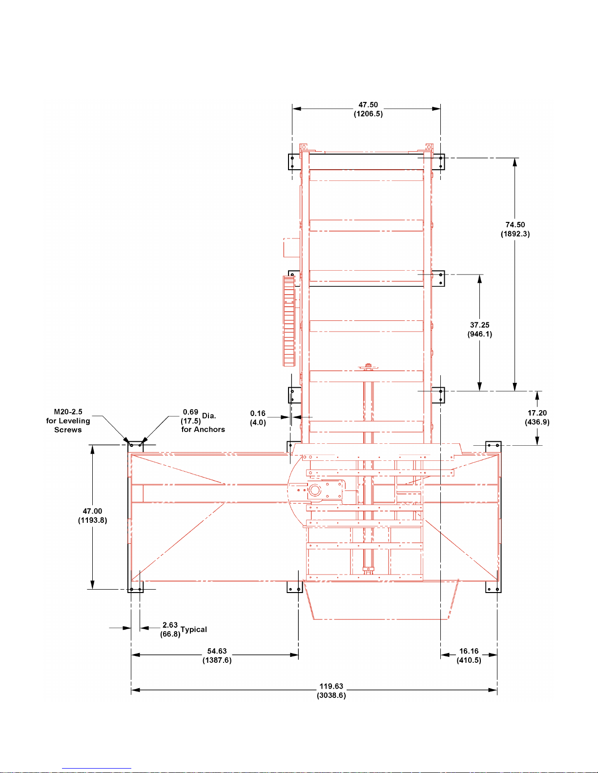
MACHINE DIMENSIONS
FLOOR PLAN/FOOT PAD LAYOUT
INCHES (± .03)
MILLIMETERS (± 1 mm)
1
Page 6
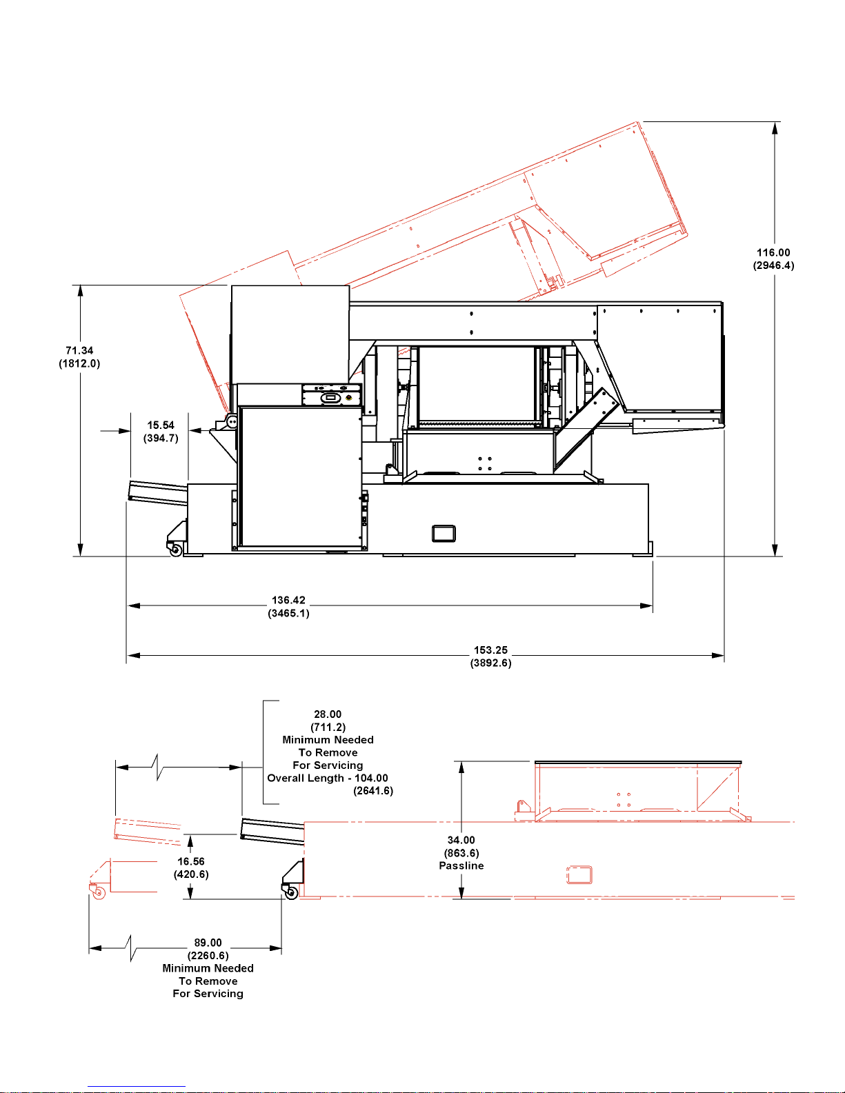
MACHINE DIMENSIONS (Continued....)
FRONT VIEW
INCHES (± .03)
MILLIMETERS (± 1 mm)
2
Page 7
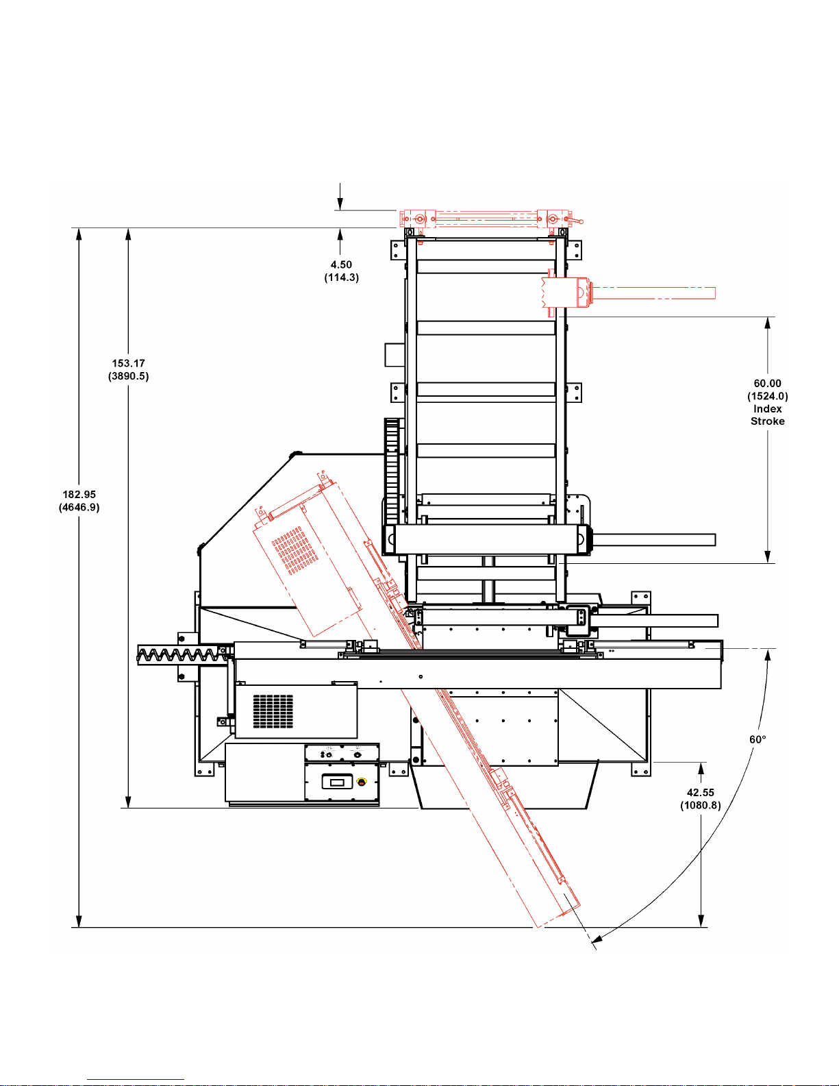
MACHINE DIMENSIONS (Continued....)
TOP VIEW
INCHES (± .03)
MILLIMETERS (± 1 mm)
3
Page 8
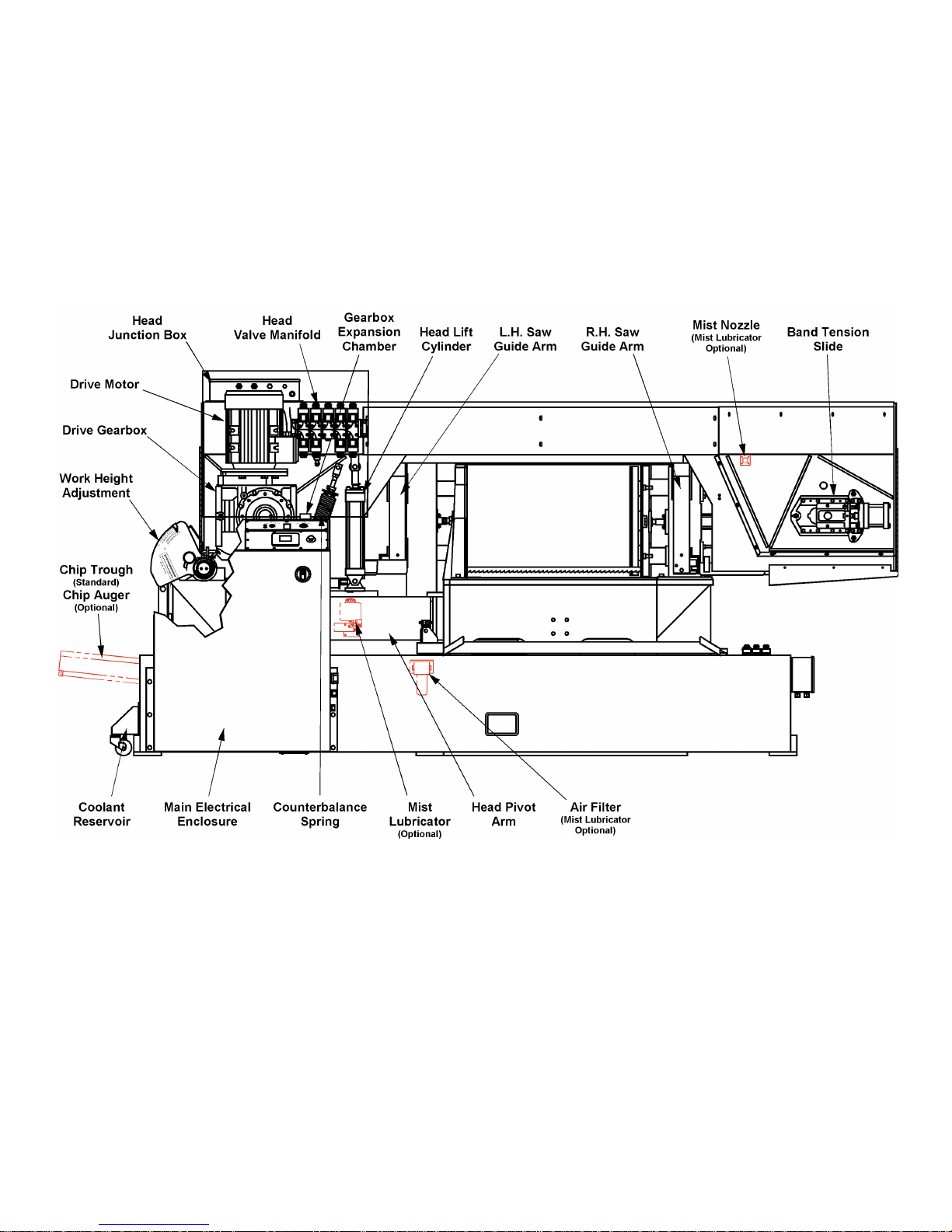
MACHINE FEATURES
FRONT VIEW
4
Page 9
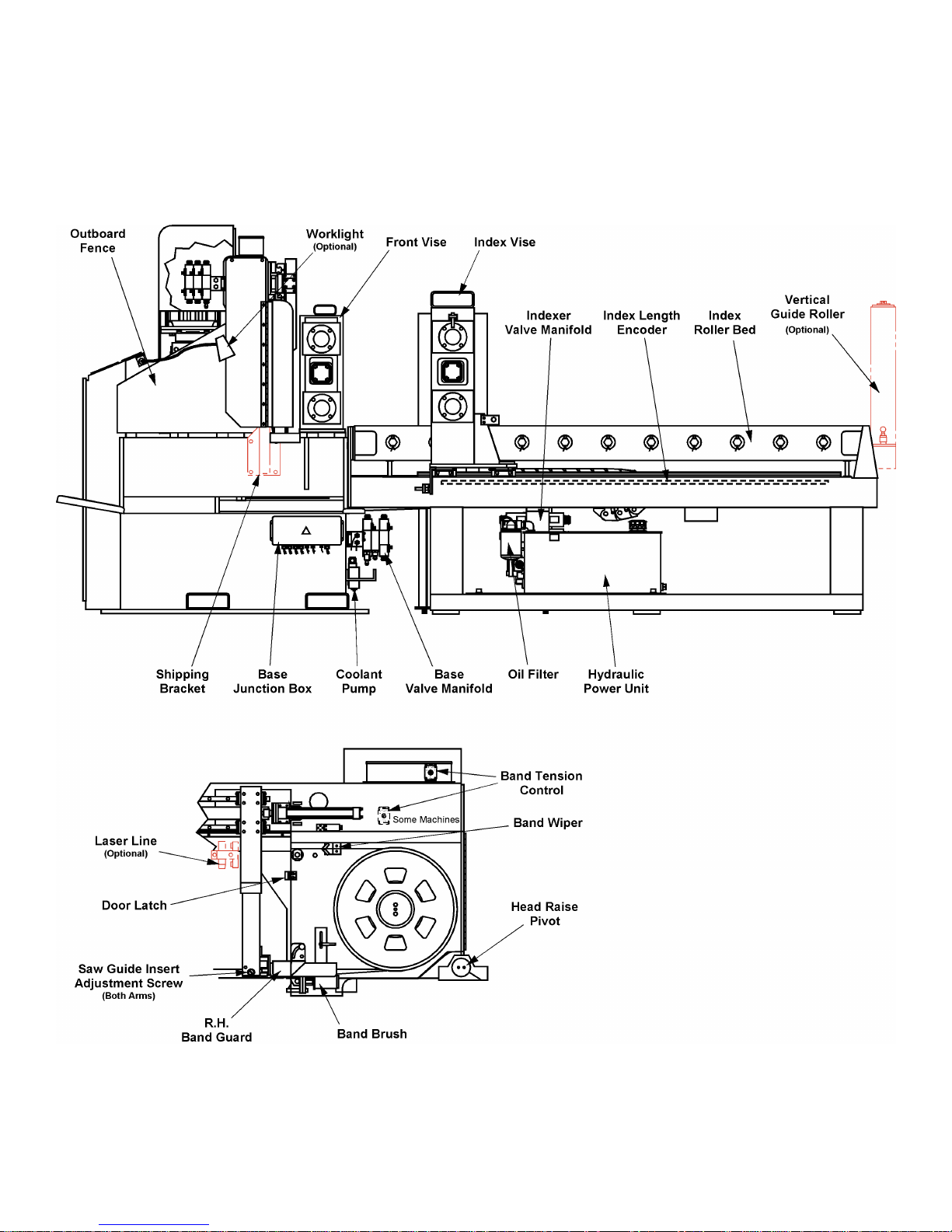
MACHINE FEATURES (Continued....)
SIDE and REAR VIEWS
5
Page 10
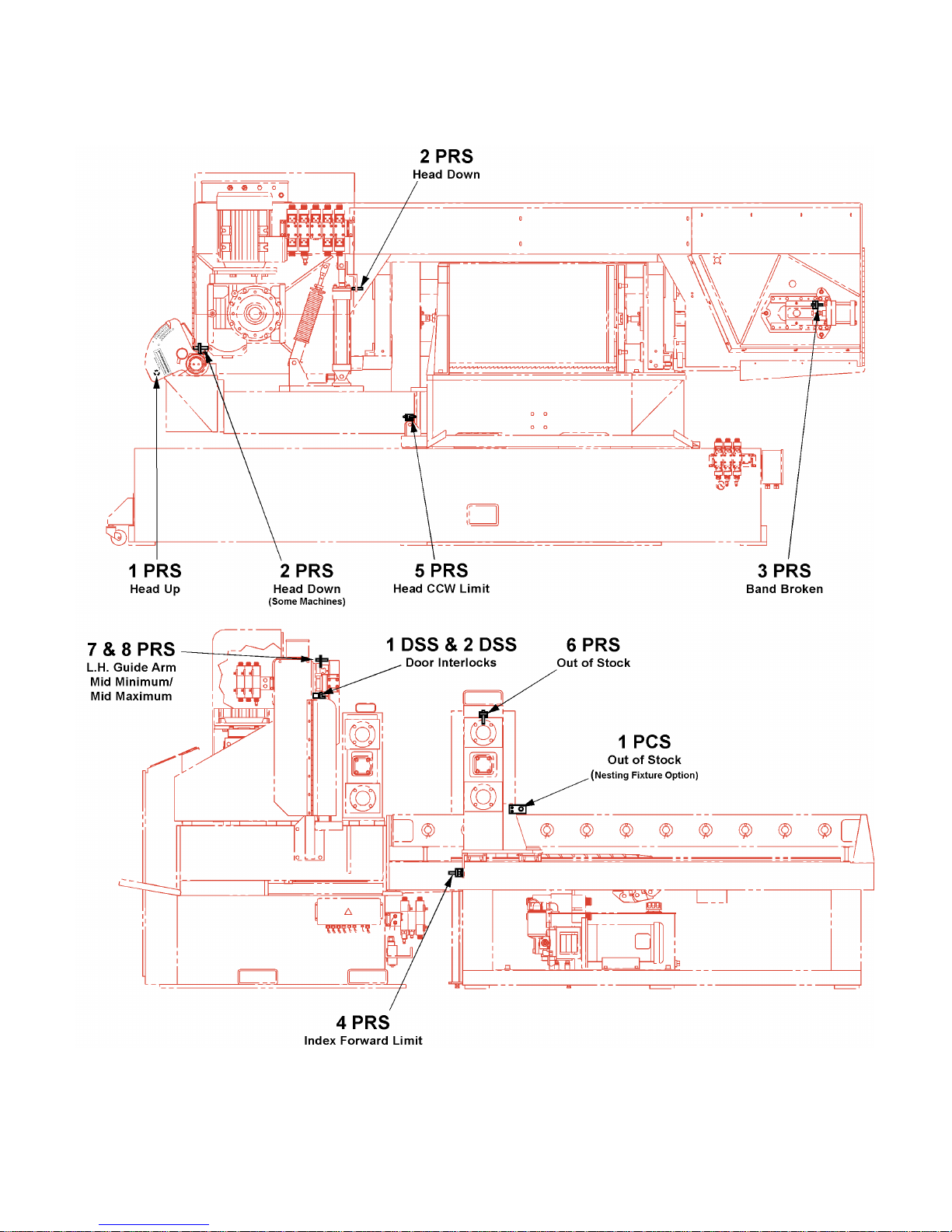
MACHINE FEATURES (Continued....)
PROXIMITY and LIMIT SWITCH LOCATIONS
FRONT VIEW
SIDE VIEW
6
Page 11

INSTALLATION
All the "left", "right", "front", "rear" directions
in this manual are as viewed by the operator
when facing the main electrical enclosure.
LOCATION
1. Position the machine to allow adequate space for all
your sawing needs with maximum convenience.
2. Locate the machine to provide sufcient clearance
for: (a) Material loading and unloading; (b) All
door openings; (c) Head elevation; (d) Head swivel;
(e) Coolant reservoir removal; (f) Chip trough or
optional chip auger removal; (g) Maintenance and
lubrication procedures; (h) Operation of the any
supplied machine accessories.
3. Approximate oor dimensions for the machine are
shown on pages 1, 2 and 3.
4. Accessories such as roller stock conveyors will
require additional working area.
UNPACKING
2. Using a fork lift truck, lift the machine by using the
lift pockets to move the machine to its permanent
location. The forks should be a minimum of six
(6) feet (2 meters) long to sufciently support the
machine.
3. Net weight for the machine base is approximately
5000 pounds (2268.0 kg). The indexer weighs
approximately 3000 pounds (1360.8 kg). Added
features and options may increase the weight by
as much as 500 pounds (226.8 kg).
The us e of an overhead hoist is NOT
recommended.
4. Optional roller stock conveyors can be lifted into
position using a fork lift or other means that provides
adequate safety precautions.
OSHA NOTICE!!
OSHA Regulation No. 1910.212 (5B).
Machinesdesignedforaxedlocationshall
be securely anchored to prevent walking or
moving.
1. The machine and other parts and supplies were
fastened to a wooden skid before shipment.
DO NOT remove the red metal bracket holding
the saw head to the vise base until the
machine has been lifted and positioned at its
permanent location.
2. Remove all protective covers, strapping, crating, etc.
Then: (a) Remove the bolts or screws attaching the
machine to the shipping skid.
3. Inspect the machine for broken or damaged parts.
Refer to this manual's inside front cover for damage
claim procedures.
CLEANING
1. If necessary, use solvent to remove the rustpreventative coating applied to the machine's
exposed bare metal surfaces before shipping.
LIFTING
Never lift the machine by its sawing head.
MACHINE INSTALLATION
1. There are two (2) parts to the machine: the machine
base and the indexer. The machine base is installed
rst and leveled before the indexer.
2. Before placing the machine down, install one (1)
M20 leveling screw and nut into each base foot
pad. Then: (a) Adjust the six (6) leveling screws
to extend an equal distance through the mounting
pad - approximately one-half inch (12.7 mm); (b)
Tighten the jam nuts; (c) Just before lowering to the
oor, place a foot casting under each leveling screw
Now lower the machine in the desired location.
3. Remove the bracket holding the saw head to the
base. Save this bracket for use in case machine
relocation becomes necessary at a future
date.
4. Place a machinist's level on the vise bed. Then
adjust the leveling screws until the vise base wear
plates are level in both directions and weight of
the machine is resting evenly on all mounting
pads.
1. Lift pockets, located on either side of the lower
portion of the base weldment, are provided for lifting
purposes.
5. Repeat Step 2 for the indexer and engage the
indexer with the locating pins on the machine
base.
7
Page 12
MACHINE INSTALLATION (Continued....)
6. Install the mounting screws and lightly tighten.
7. Adjust the indexer so both xed vise jaws are in the
same plane. Tighten the mounting hardware when
adjustment is correct.
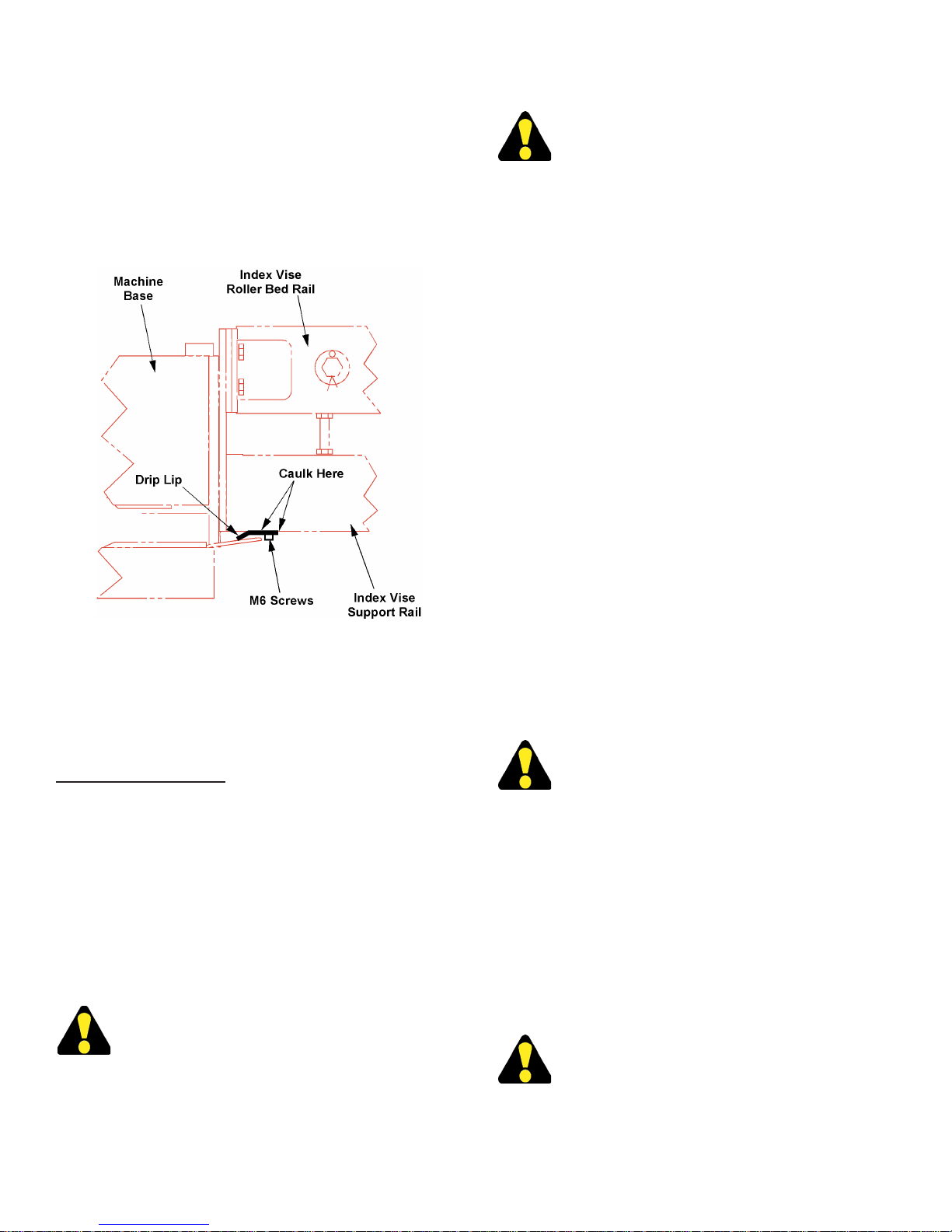
8. The drip lip is installed loosely under the support
rails of the index vise with M6 screws. Do not
tighten yet.
2. Turn the electrical supply and machine disconnect
switch to "ON".
See the "OPERATION" section under the
"Operator Workstation" heading of this
manual on how to operate the workstation
controls such as starting the hydraulics,
etc..
3. Start the hydraulics. Then raise the saw head. If
the hydraulic motor rotates correctly, the saw head
will now raise from the full down position.
4. If the saw head does not raise, it means that the
hydraulic motor’s rotation is reversed (this can
be veried by observing motor rotation). Motor
rotation must be according to the arrow on the
pump body. Hydraulic system operation cannot
be maintained if the saw head is not raised.
5. If hydraulic pump motor rotation is reversed: (a) Turn
the disconnect switch to "OFF" and remove power
at the source of electrical supply; (b) Interchange
two (2) of the L1, L2, or L3 leads to the disconnect
switch; (c) Restore power and perform Step 3
again.
Drip Lip Installtion.
9. Caulk where the drip lip comes in contact with the
support rails. Caulk the edge as well.
10. Tighten the screws. Then check for leaks by running
some uid down the drip pan on the indexer.
Relocation Procedures
1. Should machine relocation become necessary at a
later date, it will be extremely important to protect
the frame against undue stress. Before moving,
reinstall the shipping bracket connecting the saw
head to the base.
2. To move the machine, follow the instructions in the
"LIFTING" section stated previously.
ELECTRICAL INSTALLATION
Electr ical installation must be made by
authorized electrical maintenance personnel!
1. Br ing the incom ing line circui t leads to the
disconnect switch terminals in the main electrical
enclosure attached to the left side of the machine
base. Refer to the furnished electrical schematic,
if necessary.
PLANT AIR INSTALLATION (If Required)
1. Plant air is required to operate the optional mist
lubricator system.
2. Plant air is connected at the air lter on the lower
base in the front of the machine. Air pressure should
be in the range of 80 to 90 psi (5.5 to 6.2 bar or 5.6
to 6.3 kg/cm²).
DO NOT exceed 90 psi (6.2 bar or 6.3 kg/
cm²).
PREPARATION FOR USE
1. Fill the coolant reservoir with uid recommended
from the Lubrication Chart. Reservoir capacity is
approximately 25 gallons (94.6 liters).
2. Make sure all electrical connections to the machine
are tight and secure.
3. All covers and guards must be in place and all doors
must be closed.
DO NOT defeat the purpose of any guard
or safety devise. They are there for YOUR
PROTECTION!
4. The operator must understand the safety rules,
operation of the machine and has read the instruction
manual BEFORE operating the machine.
8
Page 13

OPERATION
SAFETY PRECAUTIONS
Warning Label - READ and UNDERSTAND.
USING THE SAW BAND SELECTOR
1. Refer to the Saw Band Selector label located on top
of the control console for information about blade
choice and pitch, and suggested band speed for
stock type and thickness.
Saw Band Selector.
2. For example, to cut low carbon steel which is two
(2) inches (50.8 mm) thick, you would choose a saw
band with 5-8 pitch, and set the band speed for 275
fpm (84 m/min).
CUTTING CAPACITY
1. Your machine is designed to cut rectangular stock
up to 21.00 inches (533.4 mm) high and 31.50
inches (800.1 mm) wide. It will also cut round stock
up to 21.00 inches (533.4 mm) in diameter.
2. With the saw head adjusted for 45° cutting, the
machine will saw rectangular stock up to 21.00
inches (533.4 mm) high and 16.00 inches (406.4
mm) wide and round stock up to 16.00 inches (406.4
mm) in diameter.
3. With the saw head adjusted for 60° cutting, the
machine will saw rectangular stock up to 21.00
inches (533.4 mm) high and 14.00 inches (355.6
mm) wide and round stock up to 14.00 inches (355.6
mm) in diameter.
4. The index length range is .25 to 60 inches (6.4 to
1524.0 mm) or up to 9999 inches (833.3 feet or
254.0 meters) with multiple indexing capability;
minimum indexable stock length is 26.00 inches
(660.4 mm) in automatic.
5. Vise bed capacity is approximately 3000 pounds
(1360.8 kg) evenly distributed with NO impact.
9
Page 14

MACHINE CONTROLS
1. Most controls for the machine are located on a
control console mounted on the front left side
of the machine. Controls include an Operator
Workstation, Emergency Stop pushbutton and
Hydraulic controls.
Machine Controls.
2. Feed Force. This valve regulates the amount of
pressure being placed by the saw band against the
workpiece. Turn the knob counterclockwise to
“increase” the pressure; clockwise to “decrease”
it. The valve’s lower locking knob helps maintain
the setting.
Other Controls
1. A power Disconnect Safety Switch is located on
the front of the electrical box enclosure.
Donottrytoopenthecontrolboxunlessthis
switch is turned off. Always disconnect power
to the machine before opening the electrical
controlbox.
2. Band Tension. This selector switch, located above
the drive bandwheel door, has "OFF", "HOLD"
and "ON" settings and used when changing saw
bands.
• Turning the selector to “OFF” releases band tension
and enables saw band removal or installation.
2. Emergency Stop. Pushing this red mushroom head
button stops all machine motors simultaneously.
This button must be released or reset before the
machine can be restarted.
• To reset, turn the button head clockwise until the
head pops up.
Hydraulic Controls
• The “HOLD” setting stops band tension cylinder
movement and allows the operator to position the
saw band over the bandwheels.
• The “ON” setting pressures the cylinder and
establishes band tension required for cutting.
• The Band Tension selector must be at "ON" before
the band drive motor will start or the saw head will
descend.
3. Work Height Setting Mechanism. This mechanism
allows the head to rise only high enough to clear
the work being cut. See "Work Height Adjustment"
later in this section.
OPERATOR WORKSTATION
1. There are three (3) main screens that operate the
machine: VIEW, SETUP and JOBS. Each are
described later in this section.
2. In the upper left corner on most screens is the
Display window. This window shows messages,
prompts and error messages.
Hydraulic Controls.
1. Feed Rate. This valve regulates the saw head’s
descending rate. Turn the knob counterclockwise
to “increase” the velocity; clockwise to “decrease”
it.
3. There is a set of keys in the upper right corner of
the screen. These keys access the other screens
for more machine controls, parameters and
information.
4. Certain keys will allow the operator to enter data
when pressed. A Keypad will appear when one
of these keys are activated and data then can be
entered.
10
Page 15

OPERATOR WORKSTATION (Continued....)
Power Up Procedure
If you make an error in entering data, just press
the Backspace or Clear key, correct or reenter
you value and then press the "OK" key.
1. When power is turned on, the saw head and the
index vise must be "HOMED". To home the saw head
and index vise: (a) Press the "HEAD ANGLE" key
on the View Screen; (b) Press and hold the "JOG
-" key until the message on the Display clears;
(c) Press the "EXIT" key when nished; (d) Press
and hold the "INDEXER FORWARD" key until the
message on the Display clears.
2. This procedure MUST be done each time the power
is turned on.
Keypad
1. When the operator presses a key where data may
be entered, a keypad will be displayed.
8. Enter. Pressing this key will enter the data into
memory and then will return to the previous
screen.
View Screen
1. When power is rst turned on, the VIEW Screen
appears.
2. This screen shows a collection of keys to operate
the machine manually and to enter certain data.
For the saw head and vise functions to operate,
the hydraulics MUST be on and the operation
in the MANUAL MODE.
Keypad.
2. Features of the keypad include:
3 Display Window. Located at the top of the window,
the display shows the values entered.
4. Data Limits. Below the display window will show a
"LOW" and a "HIGH" value. These values are the
low and high limits of the data that can be entered
for that function.
5. 0 - 9, Decimal Point, + / -. These keys are used to
enter values for that function. Enter them in order
including the decimal point.
6. CLR (Clear). This will clear the entry in the
display.
7. DEL (Delete). Pressing this key will delete the last
keystroke entered.
View Screen.
3. Saw Head Up. This key raises the saw head up
until the "SAW HEAD HOLD" key is pressed.
• When in "AUTO MODE", pressing the "SAW HEAD
UP" key will raises the saw head, stop the saw band
and will switch the saw to "MANUAL MODE".
4. Saw Head Hold. This key stops all saw head
movement.
5. Saw Head Down. Press and hold this key to lower
the saw head. Release the key to stop saw head
movement.
6. IndexViseClamp. Press this key will close the
index vise.
7. IndexViseOpen. Press and hold this key will open
the index vise. Release the key to stop vise jaw
movement.
11
Page 16

OPERATOR WORKSTATION (Continued....)
8. Hydraulic Start. Pressing this key starts the
hydraulic pump motor.
9. Hydraulic Stop. This key stops the hydraulic pump
motor.
10. Indexer Rapid/Creep Speed. This key toggles
between "INDEXER RAPID" or "INDEXER CREEP"
SPEED and is used to increase or decrease the index
rate of travel of the indexer when the "INDEXER
REVERSE" or "INDEXER FORWARD" keys are
activated.
11. IndexerReverse. Press and hold this key will move
the index vise away from the saw band. Release
the key to stop vise movement. At least one vise
must be open for this control to operate.
12. IndexerForward. Press and hold this key will move
the index vise towards the saw band. Release the
key to stop vise movement. At least one vise must
be open for this control to operate.
13. Band Speed. Press this key and the keypad will
appear. Enter the desired band speed and then
press "OK". The band speed can be changed at
any time.
• The "ARROW" keys below the "BAND SPEED" key
can be used to adjust the band speed in increments
of 5 fpm or 1 meter/min. depending on the "UNITS"
selection.
14. Manual/Auto Mode. This key shows the current
operating mode of the saw. Press the key will switch
between "AUTO" and "MANUAL" mode.
19. When in "AUTO MODE" , pressing the "BAND/CYLE
START" key changes to "BAND/CYCLE PAUSE".
The cycle will stop when the index vise reaches the
set point position and clamps. Then the front vise
opens to accept the next cut regardless of where
the cycle sequence is at.
• For example, if the operator pressed the key during
cutting portion of the cycle, the machine will continue
through the cycle sequence until the index vise
reaches the set point position, the front vise opens
and then the cycle will stop and the band drive motor
will stop.
• This function is usually done, for example, if the
operator needs to be away from the machine for a
time or the operator desires to check the previous
cut part.
• Pressing "BAND/CYCLE RESUME" and the cycle
will continue at the "paused" point.
For the band drive motor to start, the following
MUST be: (a) The hydraulics are on; (b) The
Band Tension control must at the "ON" setting;
(c) Both vises are clamped for auto cycle, or
front vise clamped for manual.
20. Band/Cycle Stop. This key will stop the band drive
motor.
21. Head Angle. Press this key and a screen will appear
showing various head movement options.
Head Angle Screen
15. Front Vise Clamp. Press this key will close the
front vise.
16. Front Vise Open. Press and hold this key will open
the front vise. Release the key to stop vise jaw
movement. In "MANUAL MODE", the saw head
must be up to open the vise.
17. Cut Length, Qty, Done. When "JOB MODE RUN
LIST" is selected on the SETUP Screen, these
three (3) controls are for display only showing the
current job being run. The operator must go to the
JOBS Screen to change these values.
• When "JOB MODE SINGLE JOB" is selected, these
three (3) controls are active and can be changed if
desired.
18. Band/Cycle Start. This key will start the band drive
motor.
Head Angle Screen.
1. Actual Head Angle. This display only shows the
current head angle of the saw head.
12
Page 17

OPERATOR WORKSTATION (Continued....)
2. Enter Head Angle. Press this key and the keypad
will appear. Enter the desired saw head angle and
then press "OK".
3. Rotate Head To Entered Angle. Press this key to
rotate the saw head to the angle entered above.
4. Jog +. Press and hold this key to move the saw
head in a clockwise direction. Use the "ACTUAL
HEAD ANGLE" display to help set the angle desired.
Release the key to stop saw head movement.
5. Jog - . Press and hold this key to move the saw
head in a counterclockwise direction. Use the
"ACTUAL HEAD ANGLE" display to help set the
angle desired. Release the key to stop saw head
movement.
4. Cycle Mode Home Front/Rear. This key toggles
between "HOME REAR" and "HOME FRONT" and
is used to select the position the index vise during
"AUTO MODE" cycle.
• "HOME REAR" is the shortest cycle time and is
preferred for most operations when not using the
Nesting Fixture and/or Variable Vise Pressure
options. The operator can "ENABLE/DISABLE"
the "VISE OVERLAP" feature by way of the HELP
screen under the "INDEX LENGTH PROBLEMS"
section.
• "HOME FRONT" is preferred for most operations
when using the Nesting Fixture and/or Variable Vise
Pressure options. It allows the use of both vises to
provide extra clamping (one vise is always clamped)
This is the default setting when the "NESTING
MODE" is "ON".
6. Exit. Press this key to return to the previous
screen.
Setup Screen
1. This screen shows more machine controls as well as
certain setup parameters for machine operation.
Setup Screen.
5. Job Mode Single Job/Run List. The operator
selects the type of job to run, a "SINGLE JOB"
in which the operator goes to the VIEW Screen
and enters the data for "CUT LENGTH" and
"QUANTITY".
• "RUN LIST" allows multiple jobs to be programmed
into a library. The operator must press the "JOBS"
key to access the library.
• See JOBS Screen heading later in this section of
the manual on how to create a library of jobs.
6. Units. This key allows the operator to select between
inches or millimeters (mm) for measurement data.
When switching from one to another, the data is
converted to the new measurement mode.
7. Laser (Optional). Press the key to turn the optional
laser "OFF" and "ON". The key will highlight when
it's on.
• See the "ACCESSORIES" section under the "Laser
Line Option" heading of this manual for information
on use of this option.
2. Kerf Width. Press this key and the keypad will
appear. Enter the kerf width of the saw band being
used and then press "OK".
3. Nesting Mode On/Off. When the optional Nesting
Fixture is supplied and "NESTING MODE "ON",
there is vise open time delays and "out of stock"
lengths change.
• See the "ACCESSORIES" section under the
"Nesting Fixture" heading of this manual for
information on use of this option.
8. Coolant Off. This key turns off both the Flood
Coolant system and the optional Mist Lubricator
system.
9. Coolant On With Band. Press this key for the Flood
Coolant to ow through the entire system while the
saw band is running. This is the recommended
setting.
10. Coolant On. This key operates the coolant without
the band drive motor being on and is used mainly
for the use of the ushing hose.
13
Page 18

OPERATOR WORKSTATION (Continued....)
11. Mist Coolant On W/Band (Optional). Pressing this
key activates the optional Mist Lubricator solenoid
when the saw band is running.
12. Band Change. Press this key when changing saw
bands. A screen will appear to allow the operator
to open the bandwheel doors and move the saw
head up and down as needed.
• See the "Band Change Procedures" heading later
in this section of the manual for procedures on doing
this safely.
13. Guide Arm Out. Press and hold this key to move
the right saw guide arm out away from the material.
Release the key to stop guide arm movement.
Jobs Screen.
14. Guide Arm In. Press and hold this key to move
the right saw guide arm in towards the material.
Release the key to stop guide arm movement.
15. Band VFD Fault Reset. When there is a fault in
the VFD module, pressing this key will reset the
module and operation will be allowed to continue.
16. Band Hours. This displays an accumulative
total of hours that the band drive motor has been
running.
17. IndexViseClampedDelay. Press this key and the
keypad will appear. Enter a time in seconds allotted
for the index vise jaws to clamp before indexer
movement is allowed and then press "OK".
18. Front Vise Clamped Delay. Press this key and
the keypad will appear. Enter a time in seconds
allotted for the front vise jaws to clamp before indexer
movement is allowed and then press "OK".
19. Total Hours. This displays an accumulative total
of hours that the hydraulics have been running.
2. Clear All Jobs. Pressing this key completely clears
all data on the screen.
3. Reset All Dones. When pressed, all entries in the
dones column are changed to 0 (zero).
4. To enter data in the run list: (a) Press the "#1
LENGTH" key and the keypad will appear; (b) Enter
the desired cut length and then press "OK"; (c) Press
the "#1 QTY" key and the keypad will appear; (d)
Enter the desired number of cuts and then press
"OK".
5. Press the "#2 LENGTH" and proceed as before until
the run list is completed.
Check and make any corrections/additions/
deletionstotherunlistbeforeexitingtheJOBS
Screen.Onceexited, the jobs programmed
in the list can not be changed while running
in "AUTO MODE".
6. To skip a job or jobs in the list, set the quantities to
0 (zero) on the jobs to be skipped.
Jobs Screen
1. The Jobs Screen shows a collection of keys to enter
data for running a series of cuts automatically. The
top row shows a group of keys help accomplish this
task.
• On the SETUP Screen, the "JOB MODE RUN LIST"
must active for this screen to be accessed.
7. Operator notes about entering jobs into the list: (a)
The minimum automatic index length is .250 inch
(6.0 mm); (b) The maximum index length that can
be entered is 9999.99 inches or millimeters; (c) The
maximum quantity that can be entered is 999.
Help Screen
1. This screen shows the operator a series of keys to
help solve common problems that may occur during
operation.
14
Page 19

OPERATOR WORKSTATION (Continued....)
Blade Guards
2. Press the key that matches the problem and then
follow the prompts listed.
Help Screen.
3. A key of note is in the "INDEX LENGTH PROBLEMS"
key. The operator can "DISABLE/ENABLE" the
"VISE OVERLAP" function when checking index
problems.
1. The following blade guards are positioned to provide
operator safety while the machine is running: (a) A
hinged top guard located between the bandwheel
doors. It opens and closes when the bandwheel
doors open and close; (b) A set of guards mounted
between the lower left saw guide arm and the left
bandwheel door ( one guard swivels up and has a
latch to keep it in place); (c) A guard between the
lower right saw guide arm and the right bandwheel
door. Blade guards (b) and (c) may be removed to
help facilitate saw band changing procedures.
DO NOT defeat the purpose of any guard or
safety devise. THEY ARE THERE FOR YOUR
PROTECTION!
Saw Guide Insert Adjustment
1. Adjustment screws for the saw guide inserts are
located on the lower portion of each saw guide
arm.
4. The"PLC INPUTS" and "PLC OUTPUTS" screens
show different PLC input and output modules and
their status. These modules are for diagnostics
and service only and needs NO interaction from
the operator.
5. Exit. Press this key to return to the previous
screen.
SAW BAND PREPARATION
Recommended Saw Band
1. The machine is shipped with a saw band installed.
The saw band recommended for use with this
machine is 271 inches (6883.4 mm) long, 1-1/2
inch (38.1 mm), and has a .050 (1.27 mm) gage
thickness.
Saw Guide Detail.
2. Follow these adjustment procedures: (a) Turn the
adjustment screw clockwise until the xed and the
movable inserts are tight against the saw band (do
not tighten further); (b) Turn the adjustment screw
back counterclockwise a 1/4 turn.
Band Tension
1. Band tension is factory set and will not need
adjusting for some time. Tension is applied by a
selector switch which is located above the drive
bandwheel door.
2. A new saw band will stretch as it is being used. For
this reason, it is advisable that the operator checks
the band tension frequently.
15
Page 20

SAW BAND PREPARATION (Continued....)
Using the Tensigage.
3. A DoALL Tensigage can also be used to check the
band tension. A reading of 30,000 psi (2069 bar or
2115 kg/cm²) indicates correct band tension.
Band Change Procedures - Removal
Alwaysuseextremecarewhenhandlingsaw
bands. Wear gloves.
Band Change Screen.
4. The operator can now raise and lower the saw head
with the bandwheel doors open. The "SAW HEAD"
keys operate the same as described earlier.
5. Raise the saw head to a position where the left
bandwheel door when opened clears the front vise
clamp cylinder.
A small step ladder or stool may be necessary
when reaching the idler bandwheel door and
bandwheel. DO NOT STAND on the hydraulic
manifold or valves.
1. Press the Band/Cycle Stop key. Then: (a) Swivel
the saw head away from the front vise enough
to open the bandwheel doors; (b) Move the left
saw guide arm as close to the right saw guide as
possible; (c) Unlatch both bandwheel doors and
disengage the door interlocks; (d) Move the index
vise back away from the xed front vise for ease of
access to the saw head.
3. Press the "BAND CHANGE" key and a screen
appears.
6. Open the bandwheel doors (the hinged upper band
guard also opens when the doors open). Then:
(a) Loosen the locking handle of the band brush
and move down; (b) Loosen the thumb screw of
the right blade guard and rotate up and out of the
way; (c) Rotate the left blade guard up and snap it
in the latch to hold it in place; (d) Loosen the saw
guide inserts by turning both adjustment screws
counterclockwise (do not allow the inserts to
fall out).
7. Turn the Band Tension selector switch to "OFF".
8. Place your gloved hand on the non-cutting edge of
the saw band between the saw guide arms. Then:
(a) Push the saw band downward to free it from the
saw guide inserts; (b) Grasp the saw band near the
idler bandwheel and remove it, then remove the saw
band from around the drive bandwheel; (c) Move
the saw band out and away from both saw guide
arms.
If possible, recoil the saw band into its original
holder before storing or scrapping the band.
Saw Band Installation
Alwaysuseextremecarewhenhandlingsaw
bands. Wear gloves.
16
Page 21

SAW BAND PREPARATION (Continued....)
SAW GUIDE ARM ADJUSTMENT
1. Remove the old or broken saw band as described in
the previous section. Clean metal chips and other
foreign materials and debris from around the saw
guides and both bandwheels.
2. Form the saw band into one large loop. Then: (a)
Slip the saw band under the saw guide arms and
into approximate position for placement; (b) With
the saw band's teeth facing away from you, slip
the looped saw band around the drive and idler
bandwheels.
3. Turn the Band Tension selector switch to "ON" and
then to "HOLD" to have just enough tension to keep
the saw band in place and that adjustments can be
made.
Band Twist Tool.
4. Using the band twist tool, twist the saw band 90°
so that its teeth between the saw guide arms point
down and to the right. Then: (a) Insert the saw band
into the saw guide inserts and pull up against the
back-up bearing; (b) Check the saw band's position
around the bandwheels (its back edge must rest
against each bandwheel ange); (c) Remove the
protective cap from the saw band if necessary.
5. After all corrective adjustments have been made,
turn the Band Tension selector switch to "ON".
6. Turn the saw guide insert adjustment screws
clockwise until tight (do not over tighten). Then
turn each adjustment screw back counterclockwise
a 1/4 turn.
7. Reposition the band brush and tighten the locking
handle. Then (a) Unlatch the left saw band guard
and put back in place; (b) Rotate the right saw band
guard down and tighten the thumb screw; (c) Close
both bandwheel doors and latch. Make sure both
door interlocks are engaged. Press the "EXIT" key
to return to the previous screen.
8. Press the Band/Cycle Start key. Run the machine
briey and then press the Band/Cycle Stop key.
9. Open the bandwheel doors and check for saw
band tracking. Make any corrections and close the
bandwheel doors.
1. The left saw guide arm is adjusted by using
the "GUIDE ARM OUT/IN" keys on the SETUP
Screen.
3. The best cutting results are generally obtained
when the saw guide arm are positioned as close
as possible to the stock.
When the saw head has been swiveled, make
sure the saw guide arm will clear the front vise
jaw when lowering the saw head.
FEED FORCE ADJUSTMENTS
1. Feed force is the pressure exerted by the workpiece
against the saw band's cutting edge. It is controlled
hydraulically and regulated with the Feed Force
valve. Turn the valve clockwise to "decrease"
pressure, counterclockwise to "increase" it.
2. The following are important factors to consider when
setting or adjusting the Feed Force valve:
• Turn the Feed Force valve to a low setting if the
correct feed force is not known. The operator can
then increase or decrease pressure during operation
to obtain the best cutting rate consistent with desired
blade life and stock cut nish. Always be sure to
take a good chip.
• Never start a cut with the maximum Feed Force
valve setting. Blade damage may occur.
• Certain work-hardening materials will require a
moderately heavy initial Feed Force valve setting to
assure immediate penetration of blade teeth. Light
feeds on these materials may cause the blade to slide
over the stock resulting in saw band damage.
• Generally, top performance from a sharp saw band
results from relatively low Feed Force valve
settings. It will be necessary to increase the setting
as the saw band becomes duller. This will help keep
the cutting rate constant throughout the life of the
saw band.
WORK HEIGHT ADJUSTMENT
1. The work height mechanism works in conjunction
with the head up proximity switch (1 PRS) to
assure that the saw head has raised sufciently
above the stock so manual stock positioning can
be accomplished safely.
17
Page 22

WORK HEIGHT ADJUSTMENT (Continued....)
Work Height Adjustment.
2. To adjust, lower the saw head all the way. Then:
(a) Loosen the lock knob; (b) Rotate the adjustment
ag to the desired work height indicated with the
pointer; (c) Tighten the lock knob.
3. There is a convenient metric equivalent chart for
converting the work height to millimeters.
FLOOD COOLANT SYSTEM
Coolant Selection
1. Excessive heat build-up is the main cause of blade
tooth failure during band machining. Coolant
has both lubricating and cooling properties. Its
application does the following: (a) Helps reduce
the heat generated during sawing; (b) Helps prolong
blade life; (c) Generally promotes more efcient
cutting rates.
2. When making a coolant choice, the operator will
want to consider the following points: (a) The type of
material being cut; (b) The material's machinability
rating; (c) Band speed and feed rate to be used;
(d) Saw band type to be used and its expected life;
(e) The overall sawing operation.
3. Using more than one (1) coolant variety may provide
maximum sawing results and economy.
Literature describing different coolant types
and their application is available from a DoALL
sales representative.
Coolant Application
SAW HEAD POSITIONING FOR ANGLE CUTS
1. To position the saw head for angle cutting from 0°
to 60°, press the "HEAD ANGLE" key. Then: (a)
Press the "ENTER HEAD ANGLE" key and the
keypad will appear; (b) Enter the desired saw head
angle and then press "OK"; (c) Press "ROTATE
HEAD TO ENTERED ANGLE" to move the saw
head to the entered angle.
2. The operator may use the "JOG +/-" keys to move
the saw head to the desired angle. Press and hold
the appropriate "JOG" key and release when the
desired angle has been reached.
3. See also the "HEAD ANGLE SCREEN" heading
previously described in this section of the manual.
The width capacities of the machine are
reduced when angle cutting.
1. Coolant is supplied by means of a reservoir and
pump to the cutting area through the saw guide
inserts on the saw guide arm. A valve on each saw
guide arm regulates the ow to the saw guides.
Turn the valve counterclockwise until coolant
completely covers both sides of the saw band.
2. Used coolant ows back to the reservoir by means
of a trough in the saw base. The reservoir has a
ltering screen surrounding the lter element to
keep out metal particles and other impurities.
Coolant Pump and Reservoir.
18
Page 23

FLOOD COOLANT SYSTEM (Continued....)
3. Coolant reservoir capacity is 25 gallons (94.6 liters).
The pump will not operate correctly unless the lter
element is completely submerged in coolant.
Flushing Hose
1. Part of the Flood Coolant System, the ushing hose
is attached to the coolant pump and delivers cutting
uid through a hand nozzle. It is used primarily for
machine cleaning purposes.
Band Brush.
DRY CUTTING
1. The operator may nd it desirable to cut some
materials (such as cast iron, aluminum, magnesium,
etc.) without coolant. When dry cutting these
materials, follow the same operating procedures
used when cutting with coolant. However, dry
cutting will reduce saw band life.
HYDRAULIC SYSTEM
1. The hydraulic and band drive systems operate
independently. This allows the operator to perform
the following tasks while the band drive motor is
not running: (a) Change saw bands; (b) Raise or
lower the sawing head; (c) Swivel the sawing head;
(d) Clamp or unclamp the vises; (e) Position stock
manually.
2. The machine's hydraulic reservoir has a 15 gallon
(56.7 liter) capacity. Refer to the Lubrication section
of this manual for recommended iuds.
BAND BRUSH AND CHIP REMOVAL
Band Brush
1. A hydraulic motor driven band brush is located
inside the drive bandwheel door. During machine
operation, the brush bristles should be positioned
so that the tips clean chips from the blade teeth
gullets, but do not contact the bottom of the gullets.
DO NOT allow metal chips to accumulate on the
brush.
2. The brush must be properly adjusted to clean blade
tooth gullets if satisfactory sawing performance
is to be obtained. As bristles wear down, adjust
brush position by: (a) Loosening the bolts holding
the bracket to the saw head; (b) Move the brush to
the correct cleaning position; (c) Retightening the
bracket bolts.
NEVER adjust the band brush while the saw
band is running.
Chip Removal
1. During operation, metal chips and used coolant
drop directly into a sloped trough, or ow into it from
the machine's run-off surfaces. Metal fragments
removed from the band brush also drop onto the
saw base. Coolant then ows down the trough
and through a ltering screen before returning to
the reservoir. The ushing hose helps collect the
chips into the trough.
2. The chip trough collects the metal chips and can
be raked to the opening at the machine's left side
where chips can be emptied into a customer-supplied
container.
Flushing Hose
1. Metal chips and other debris may accumulate over
time around such machine areas as: saw guides,
both bandwheels, vises, slides, band brush, head
lift cylinder, feed and discharge areas, etc.
2. The operator should check often for metal chip
collections which can adversely affect machine
performance. They should be removed with either
the combination shovel-rake or the Flushing Hose
as soon as possible.
It is recommended that the operator remove
chips at least twice per each eight (8) hour
shift, and more often with heavier use.
Be sure the saw ba n d ha v e STO P P E D
completely before cleaning the machine.
19
Page 24

TYPICAL OPERATION PROCEDURES
Preparation
1. These operations assume that the machine is
prepared as follows: (a) The band drive motor is
"OFF"; (b) The saw band is properly installed and
tensioned; (c) Both bandwheel doors are closed;
(d) All guards are in place and/or secured; (e) The
coolant reservoir or the optional Mist Lubricator
reservoir is full and all lubrication points are properly
serviced; (f) The band brush is properly positioned;
(g) The work height is adjusted for material size.
Manual Operation
1. Press a "COOLANT" key selection that is correct
for the application.
2. Go to the VIEW Screen, make sure the "MANUAL
MODE" key is activated.
3. Press the "HYDRAULIC START" key.
9. Press the "FRONT VISE CLAMP" key to clamp the
stock. Then: (a) Press the "SAW HEAD DOWN"
key and release the "SAW HEAD DOWN" key when
the saw band is just above the stock to be cut; (b)
Press the "BAND SPEED" key and enter the desired
speed and press "OK".
10. Press the "BAND/CYCLE START" key. As the saw
band drive comes up to speed and coolant begins to
ow, the saw head will descend when the operator
adjusts the Feed Rate control counterclockwise
to begin saw head feed.
11. The operator may adjust band speed, coolant ow,
feed rate, and/or feed force at any time during the
sawing process.
DO NOT remove the cut-off piece until the saw
band has stopped completely.
12. After the cut has been completed, the saw band
will shut off with the saw head in the down position.
Remove the cut-off piece.
4. Go to the VIEW Screen and then press the "SAW
HEAD UP" key. Raise the saw head all the way to
the head clear position. The vises are now enabled
be opened to its full open position.
5. If necessary, swivel the saw head by pressing the
"HEAD ANGLE" key. Enter the angle desired and
proceed.
6. Press and hold the "INDEX VISE OPEN" key to
open the vise wide enough for stock to be placed
between the jaws. Release the keys to stop vise
movement. Repeat the action for the front vise.
7. Load the stock to be cut onto the indexer roller bed
near the xed vise jaws and manually position for
a crop cut if desired.
• To move the stock into position for clamping using the
indexer: (a) Press the "INDEXER REVERSE" key to
move the index vise to the rear limit of its travel; (b)
Press the "INDEX VISE CLAMP" key to clamp the
stock; (c) Press the "INDEXER FORWARD" key to
position the stock extending beyond the saw band
and enough stock for the front vise to clamp.
8. On the hydraulic control panel, turn the Feed Rate
control fully clockwise to stop the feed.
13. If more cuts are to be made: (a) Raise the saw
head until the desired saw head height is reached;
(b) Unclamp the vise jaws; (c) Position stock for
another cut; (d) Clamp the vises; (e) Press the
"BAND/CYCLE START" key.
Automatic Operation
1. Go to the SETUP Screen and press the "VISE
CLAMPED DELAY" key(s) to change the time delay
values (if desired), enter the value for each using
the pop-up keypad and then press "OK".
2. Follow steps 2 through 7 of the "Manual Operation"
section.
3. Go to the SETUP Screen and select either the "JOB
MODE SINGLE JOB" or "JOB MODE RUN LIST".
• If the "SINGLE JOB" mode is selected, go to the
VIEW Screen and enter the cut length and quantity
of parts desired.
• If the "RUN LIST" mode is selected, go to the
JOBS Screen and start entering the cut length and
quantity of parts for each job to be done using the
pop-up keypad. Make sure to press "RESET ALL
DONES" to clear the "DONE" column.
DO NOT over tighten. To prevent damage to
the Feed Rate valve, turn only enough to seat
the needle of the valve.
4. Clamp both front and index vises. Both vises must
be clamped for the automatic cycle to operate.
20
Page 25

TYPICAL OPERATION PROCEDURES
(Continued....)
5. Press the "BAND/CYCLE START" key. As the saw
band drive comes up to speed, the index vise jaws
open, the indexer moves to a full forward position
to reset, and then moves back to the set index cut
length and clamps. The saw head will descend
when the operator adjusts the Feed Rate control
counterclockwise to begin saw head feed.
6. After the rst cut has been completed: (a) The saw
head will raise just above the material; (b) The xed
vise will open and the index vise moves the material
forward for the next cut; (c) When the forward stop
is reached, the xed vise clamps, the indexer moves
back to the set index cut length and clamps and the
saw head lowers to make the next cut.
7. The operator may adjust band speed, coolant ow,
feed rate, and/or feed force at any time during the
sawing process.
8. There is several ways in which the operator may
stop the sawing cycle:
• Pressing the "SAW HEAD UP" key. The saw head
will move to the head up limit, the saw band will
stop and the saw will go to manual mode.
• Pressing the "BAND/CYCLE STOP" or the "AUTO
MODE" keys. The saw band will stop and puts the
saw into manual mode.
• Press the "BAND/CYCLE PAUSE" key.
9. The automatic cycle will continue to cycle until all
programmed jobs have been completed.
10. When the number of cuts has been reached, the
saw head will stay in the down position and the band
drive motor will shut off.
DO NOT remove any cut-off pieces until they
are away from the saw band or the saw band
has stopped completely.
For future reference, keep a record of band
speed, feed rate and coolant application
settings for successful jobs.
21
Page 26

LUBRICATION
LUBRICATION CHART
LUBRICATION
POINT NO.
1
2
3
4
5
6
7
8
9
10
11
12
13
14
LOCATION DESCRIPTION and
SERVICE RECOMMENDATIONS
Bandwheel Bearings. One (1) grease tting each
bandwheel.
IndexViseLinearBearings. Four (4) grease ttings. MONTHLY
Saw Guide Arm Linear Bearings. Four (4) grease ttings. MONTHLY
Band Tension Slide. Two (2) grease ttings. 6 MONTHS
Vise Movable Jaw Ways. Clean and apply oil. MONTHLY
Head Raise Pivot Shaft Bearing Surface. Apply oil. MONTHLY
Head Swivel Pivot Shaft Bearing Surface. Apply oil. MONTHLY
Miscellaneous: Vise Slide, Hinges, Pivot Points,
Component Parts, Unpainted Surfaces, etc. To ensure
function and maintain appearance while reducing wear,
corrosion, rust, etc. Apply when and where needed in
amounts required.
Saw Guide Adjustment Screws. Clean and apply oil. INSERT CHANGE
BandDriveGearbox. Three (3) gallons (11.4 liter) capacity.
Fill very slowly so oil can seep through bearings, gears, etc.
Fill to the top of elbow. DO NOT OVERFILL.
Electric/Hydraulic Motors. Drive, Hydraulic Pump, Band
Brush, Chip Auger, Nesting Clamp (If Supplied).
Flood Coolant Reservoir. 25 gallon (94.6 liter) capacity.
Drain, clean and rell whenever coolant becomes undesirable
for further use. Clean the mesh screen at the same time.
Band Mist Lubricator (Optional). 32 ounces (1.0 liter)
capacity. Keep lled and hoses clear.
Hydraulic Reservoir. Twelve (12) gallon (56.8 liter) capacity.
Check uid level daily and keep the reservoir full. Drain,
change the lter element and rell after the 1st month; every
six (6) months thereafter.
LUBRICATION
INTERVAL*
WEEKLY
AS REQUIRED
18,000 HOURS
OR 2 YEARS
Lubricate (if any) per manufacturer's recommendations.
CHECK DAILY/
AS REQUIRED
CHECK DAILY/
AS REQUIRED
CHECK DAILY/
AS REQUIRED
RECOMMENDED
LUBRICANT
Premium quality, multi-purpose lithiumbase, EP (extreme pressure) grease.
NLGI No. 2.
Union 76, UNOBA EP 2, or equivalent.
High quality, rust and oxidation-inhibited,
medium hydraulic and general purpose
industrial oil.
ISO-VG Grade 68 (Formerly ASTM
Grade No. 315).
Union 76, UNAX RX 68, or equivalent.
High quality, rust and oxidation-inhibited,
gear lubricant.
ISO-VG Grade 90.
Mobil HD 80W-90, or equivalent.
Premium quality, saw band coolant and
lubricant.
DoALL cutting uids and/or oils (Kool
All).
Contact your DoALL sales representative
for the best oils or uids for your
application.
DoALL cutting uids or oils (AL-2000).
Multi-purpose automatic transmission
uid.
General Motors Dexron III, or equivalent.
22
Lubrication intervals are based on a 8-hour day, 40-hour week.
*
Lubricate more often with heavier use.
Page 27

LUBRICATION DIAGRAM
FRONT VIEW
SIDE VIEW
REAR HEAD VIEW
23
Page 28

MAINTENANCE
REPLACING SAW GUIDE INSERTS
These instructions can be used on both left and
right saw guide arms. It is also recommended
that both saw guide insert sets be replaced at
the same time.
The band drive motor MUST not be running
when replacing saw guide and back-up
inserts.
1. Release band tension. Then: (a) Loosen the saw
guide adjustment screw on each saw guide arm; (b)
Move both the left and right saw band guard and
swing them out of the way; (c) Remove the saw band
from the saw guide inserts and saw guide arm.
2. Remove the adjustment screw being very careful
not to drop or lose the front insert when it falls
from the assembly.
3. Loosen the socket head cap screw and remove the
xed (rear) insert.
ADJUST OR REPLACE SAW BAND GUIDE
ROLLERS
1. To adjust and position the xed guide rollers: (a)
Raise the saw head until the saw band is above
the front movable vise jaw; (b) Shut the machine
and disconnect switch off.
2. Position the bearing blocks so that the xed spindle
rollers bear evenly on the straightedge gage.
3. Loosen the set screw above the roller bearing and
pull out the roller bearings. Then: (a) Remove the
screw or retaining ring holding the bearing in place;
(b) Remove old bearing and replace with new one;
(c) Reinstall the screw or retaining ring; (d) Tighten
the set screw.
Typical Saw Guide Assembly (Both Arms).
4. Thoroughly clean the saw guide arm and inserts
area. Then: (a) Reverse (ip 180°) the carbide
back-up insert (if worn, replace when both sides
are worn); (b) Install the xed inserts rst and then
the adjustable ones.
5. Thread the adjusting screw inward part way. Then:
(a) Place the saw band between the inserts; (b)
Tighten the adjustment screw; (c) Reposition the
left and right saw band guards.
Saw Guide Roller Bearings.
HYDRAULIC SYSTEM
1. Keep the reservoir lled at all times. Capacity is 12
gallons (56.8 liters). Check the reservoir oil level
daily by referring to the sight gauge.
2. Drain, clean, rell the reservoir and change the oil
lter after the rst month of operation; every six (6)
months thereafter. Clean the suction strainer and
ller opening screen when necessary. Automatic
transmission uid is the recommended product.
3. Before changing the hydraulic oil: (a) Lower the
saw head completely; (b) Push the Hydraulic Stop
key; (c) Remove the reservoir drain plug; (d) Allow
the reservoir to drain completely.
24
Page 29

HYDRAULIC SYSTEM (Continued....)
System Pressure
1. Hydraulic system pressure is correctly set at the
factory and should not require adjustment for
a considerable period of time. Correct system
pressure is 700 ±25 psi (48.3 ±1.7 bar or 49.2 kg/
cm².).
2. Pressure is adjusted by turning the screw extending
outward from the hydraulic reservoir. Consult
a DoALL service representative if assistance is
needed.
Pump Repair & Replacement
2. Check the coolant often for signs of contamination
or breakdown. The reservoir and coolant system
should be drained and cleaned thoroughly when the
cutting uid becomes undesirable for further use.
If another type of coolant is to be used, the entire
coolant system must be ushed (use DoALL’s Kleen
Flush).
3. To thoroughly clean the reservoir section below
the conveyor trough, removal of the trough will be
necessary.
MACHINE CLEANING
1. Keep the machine and its parts as clean as possible
to prevent excessive wear and damage.
1. DO NOT attempt to repair the hydraulic pump.
Return it to the factory for repair or replacement. Be
sure to specify the correct pump model and serial
numbers when returning the unit.
2. Following a new pump installation: (a) Jog the
Hydraulic Start and Hydraulic Stop keys several
times; on for two (2) seconds, off for three (3) seconds
until the pump is primed; (b) Check for proper pump
rotation while jogging; (c) Review wiring connections
if the pump rotates in the wrong direction.
After the pump has been primed, run it
for several minutes while operating the
machine’s controls to purge entrapped air
from the pump and system. Check for oil
leaks while the system is being operated.
Seals & Cups
1. Seals and cups used in DoALL hydraulic systems
are compatible ONLY with hydraulic oils having an
aniline point between 215° and 230° F. (102° and
111° C.).
2. Use the Flushing Hose as soon as possible to remove
metal chips and other waste materials which may
collect around the saw guides, bandwheels, vises,
slides, sensing arm, etc. The hose has a handoperated valve and attaches to the coolant pump.
The DoALL Company recommends using the
Flushing Hose to remove chips at least twice
per each eight (8) hour shift, and more often
with heavier use.
3. Use the supplied chip rake to remove accumulated
metal chips or other waste materials from machine
areas. Be sure the band drive motor is stopped
before opening machine doors or covers.
Chip Rake.
2. If hydraulic oil having an aniline point not falling
within the above range is used, the seals may either
swell or shrink and harden. This causes machine
malfunction and leakage.
DoALLhydraulicuidwithananilinepointof
approximately221°F.(106°C.)willnotcause
deterioration of component seals.
FLOOD COOLANT SYSTEM
1. The machine’s coolant reservoir has a 25 gallon
(94.6 liter) capacity. A reservoir level sight gauge
is located at the machine’s right front side.
MACHINE ALIGNMENT
1. Misalignment of the machine’s saw guide arms, slide
bar, saw band, pivot points, transmissions, etc., will
cause inaccurate sawing.
DO NOT attempt any alignment procedures
not covered by this manual. Contact a
DoALL service representative in such cases
becausespecialxturesandtechniquesmay
be required.
25
Page 30

BAND BRUSH
Vise Bed Wear Plates
1. The band chip brush will wear and lose steel bristles
over time. Check often to be sure the bristles are
removing metal chips from the blade tooth gullets,
but are not touching the bottom of the gullets.
2. Move the brush closer to the blade as normal wear
occurs. Replace the brushes when necessary.
BAND TENSION MEASUREMENT
1. Band tension is factory set.
• Band tension measurement can be made with the
machine’s hydraulics running and by using the Band
Tension selector and a DoALL Tensigage.
2. Tension may be checked "reading up" or "reading
down". To "read up": (a) Fix the Tensigage to a
slack saw band; (b) Apply tension. To "read down":
(a) Fix the Tensigage to a tensioned saw band; (b)
Relax tension.
3. A DoALL Tensigage reading of 28,500 to 30,000 psi
(1965 to 2069 bar or 2004 to 2115 kg/cm²) indicates
correct saw band tension.
1. Each of the two (2) front vise bed wear plates
has twelve (12) mounting screws which must be
removed. Replacement requires: (a) Removing
the mounting screws from large outboard wear plate
rst; (b) Removing the mounting screws from the
two (2) wear plates and then slide them out from
under the vise jaw.
2. Replace the wear plates in reverse order and install
the hardware.
BAND DRIVE GEARBOX
1. Band drive gearbox replacement, repair, adjustment
or alignment should be performed only by a DoALL
service representative.
Using a Tensigage to Measure Band Tension.
WEAR PLATE REPLACEMENT
1. The removable vise jaw and vise bed wear plates
must be replaced before excessive wear causes
the mounting screw heads to become damaged
and makes removal difcult.
Vise Jaw Plates
1. The machine has six (6) vise jaw wear plates: two
(2) on the front vise movable jaw and four (4) on
the index vise jaws. All wear plates are mounted
with low-head screws. Be sure the vise jaws are
separated and the machine turned off before
trying to replace the wear plates.
Drive Gear Box.
2. To change the oil, drain the oil through the drain plug
as shown. Fill with three (3) gallons (11.4 liter) of
oil until the oil level is to the top of the elbow.
Fill very slowly so the oil can seep through
the bearings, gears, etc. This may take a few
minutes.
BANDWHEELS
Bandwheel Flange and Tread.
26
Page 31

BANDWHEELS (Continued....)
1. Occasionally check each bandwheel’s back-up
ange and wheel tread for wear. Saw bands will
not track properly if the taper is worn from the wheel
tread.
2. Replace the entire bandwheel if the rim becomes
badly worn.
3. Ideally, the saw band should be tracking on both
wheels so that the back edge will just lightly contact
the wheel anges, or is not more than 0.005 inch
(0.127 mm) away from the anges.
CLEANING CHIP TROUGH OR CHIP AUGER
1. To clean the chip trough or optional chip auger,
turn the machine off. Then: (a) Remove the cover
and pull the trough or auger (disconnect the auger
hydraulic hoses rst) from its cradled position in
the base/coolant reservoir; (c) Clean the removed
trough and the trough in the base as well; (d) Clean
the reservoir oor; (e) Replace the trough or auger
and reinstall the cover.
2. The machine’s coolant reservoir has a 25 gallon
(94.6 liter) capacity.
3. Check the coolant often for signs of contamination
or breakdown. The reservoir and coolant system
should be drained and cleaned thoroughly when the
cutting uid becomes undesirable for further use.
If another type of coolant is to be used, the entire
coolant system must be ushed (use DoALL’s Kleen
Flush).
Counterbalance Spring.
Be sure the saw head falls only enough to
cut completely through the work. TOO MUCH
head fall could result in cutting the vise bed
wear plates too deeply or completely off. TOO
LITTLE head fall will result in an incomplete
cut through the workpiece.
ELECTRIC MOTORS
1. Follow the manufacturer's maintenance instructions
for each electric motor. These instructions are
located in the pocket inside the main electrical
enclosure.
4. To thoroughly clean the reservoir section below
the chip trough, removal of the trough will be
necessary.
COUNTERBALANCE SPRING
1. After a period of time, the saw head may not cut
through the stock or cuts too far into the vise bed
wear plates. To adjust, follow these procedures:
• There is no need to remove the counterbalance
spring from the machine. (a) Loosen the threaded
collar from the lower hex nut; (b) Adjust the lower
hex nut up or down until the saw band teeth are
approximately 0.06 inch (1.52 mm) below the work
surface; (c) Turn the threaded collar down tightly
on top of the hex nut and secure it.
MIST LUBRICATOR
1. See the instructions sent with the unit for information
on maintenance and adjustments. They are located
in the pocket inside the main electrical enclosure.
27
Page 32

TROUBLE SHOOTING
Repair and adjustment procedures should
be made only by experienced maintenance
personnel. Reference to the machine's
electrical and hydraulic schematics will be
helpful.
MACHINE WON'T START
1. Make sure the disconnect switch is turned to
"ON".
2. Make sure that the bandwheel doors are closed.
3. Hydraulics must operating before the band drive
motor can be turned on.
4. Make sure the Emergency Stop pushbutton is reset
(turn the button head clockwise).
5. A circuit breaker has tripped. Flip to "OFF" rst,
then to "ON".
6. Raise the saw head to deactivate the head down
proximity switch (2 PRS).
7. Check for a burned out band drive motor.
8. Check the incoming leads, fuses, wiring, and control
circuit fuse for possible malfunction.
MACHINE STARTS, BUT WON'T CONTINUE
RUNNING
1. Check for defective band drive contactor in the main
electrical box.
2. The saw head has not cleared the head down
proximity switch (2 PRS). Move the saw head up.
INACCURATE CUT-OFF
1. Saw band teeth are dull or worn.
2. T h e b a n d b r u s h n e e d s a d j u s t m e n t o r
replacement.
3. Increase the band speed or decrease the feed
rate.
4. Check for dirty coolant. Replace if necessary.
6. Stock is crooked. This usually results in straight,
but not square cuts.
7. Decrease the distance between the saw guide arms.
Move the left arm as close as possible to the stock
being cut.
8. Check for incorrect blade pitch being used.
9. Band tension is incorrect.
10. Stock is not being held rmly between the vise
jaws.
11. Check for incorrectly adjusted saw guide inserts
and back-up bearing.
12. Check for machine misalignment (have a service
representative check and/or adjust machine
alignment).
SQUARENESS PROBLEMS
1. Go to the HELP Screen and press "SQUARENESS
PROBLEMS" and follow the prompts if any.
VERTICAL CUT INACCURACY (Cut piece are
thicker at the top or bottom)
1. Check for loose or worn saw guide inserts. Tighten
the inserts if loose, replace inserts if worn.
2. Reduce the feed rate being used.
3. Check for crooked stock and/or incorrect stock
positioning between the vise jaws.
4. Move the left arm as close as possible to the stock
being cut.
5. Check for incorrect band tension adjustment.
6. Stock is not being held rmly between the vise
jaws.
7. Check for a worn saw band.
8. Check for saw head vertical misalignment. Have
a service representative check and/or adjust saw
head alignment.
5. Coolant is not being supplied evenly to both sides
of the saw band.
28
Page 33

TROUBLE SHOOTING (Continued....)
HORIZONTAL CUT INACCURACY (Cut piece
are thicker on one side)
1. Check for loose or worn saw guide inserts. Tighten
the inserts if loose, replace inserts if worn.
2. Check that the saw head angle is at 0° and locked
in place.
3. Check for crooked stock and/or incorrect stock
positioning between the vise jaws.
3. Saw band is being dropped into the stock. Decrease
the feed rate.
4. Increase the band speed and/or decrease the feed
rate.
5. Stock is not being held rmly between the vise
jaws.
6. Check for improper adjustment of the saw guide
inserts and back-up bearing.
7. Install a ner pitch saw band.
4. Check for incorrect coolant application.
5. Stock is not being held rmly between the vise
jaws.
6. Che c k fo r machine misalig n m e nt. Have a
representative check and/or adjust machine
alignment.
BAND TEETH STRIPPING
1. Increase the band speed or decrease the feed
rate.
2. Check for chip welding, or for a chipped blade tooth
lodged in the cut.
3. Check for faulty stock: heavy scale, inclusions, hard
spots, etc.
4. Band brush needs adjustment or replacement.
5. Blade pitch is too course if a thin stock section is
being cut.
8. Increase the coolant volume being supplied.
BAND TOOTH GULLETS LOADING
1. Use a courser pitch saw band.
2. Increase the band speed or decrease the feed
rate.
3. Band brush needs adjustment or replacement.
4. Check for incorrect coolant application.
5. Check for incorrect band tension adjustment.
PREMATURE BAND TEETH DULLING
1. Band speed and/or cutting rate is too high.
2. Check for faulty stock: heavy scale, inclusions, hard
spots,etc.
3. Stock analysis is incorrect. This can result in the
wrong initial cutting recommendations.
6. Check for vibration caused by stock not being held
rmly between the vise jaws.
7. Check for worn saw guide inserts and/or back-up
bearing.
8. Coolant is not adequately covering both sides of
the saw band.
9. Check for incorrect band tension.
PREMATURE SAW BAND BREAKAGE
1. Check for a poor weld in the saw band, or for
incorrect band tension.
2. Check for incorrect band tension.
4. Check for coolant not covering the saw band
completely.
5. Check for saw band vibration or chip welding.
6. Check for a chipped blade tooth lodged in the cut.
7. Incorrect saw band is being used.
8. Check for incorrect band tension adjustment.
9. Incorrect coolant is being used, or the mixture is
too weak.
10. Decrease the feed rate during the rst few cuts to
break-in the saw band if new.
29
Page 34

TROUBLE SHOOTING (Continued....)
SAW BA ND RUN NIN G IN THE WRO NG
DIRECTION
1. Switch any two (2) of the incoming electrical lines.
HIGH FREQUENCY SQUEAL DEVELOPS
WHILE SAWING
1. Increase the feed rate (rate being used is not
compatible with the size or type of material being
cut).
SAW BAND STALLS DURING A CUT
1. Decrease the feed rate or increase the band
speed.
2. Check for incorrect band tension adjustment.
3. Use a ner pitch blade -- at least three (3) teeth
should be in the stock at all times.
4. Check for a worn or slipping drive motor belt.
5. Excessive coolant are making the bandwheels
slippery.
SAW BAND VIBRATION
1. Check for incorrect blade pitch choice.
2. Band speed being used is incorrect.
3. Coolant choice is incorrect, or the mixture is too
weak.
4. Make a saw head feed rate adjustment.
5. Stock is not held rmly between the vise jaws.
6. Check for worn or improperly adjusted saw guide
inserts.
2. Increase the coolant volume.
3. Use a courser pitch saw band.
4. Reduce or vary the band speed.
5. Check the band tension setting.
CUT-OFF PIECE SURFACE FINISH IS TOO
ROUGH
1. Check for machine or saw band vibration.
2. Check for a dull or damaged saw band.
3. Use a ner pitch saw blade.
4. Check for worn saw guide back-up bearings.
Replace if necessary.
5. Band tension setting is incorrect.
6. Increase the band speed or decrease the feed
rate.
7. Check for incorrect coolant type being used.
CUTTING RATE IS TOO SLOW
1. Use a courser pitch saw blade.
7. Check for a worn saw guide back-up bearing.
8. Check for a dull or damaged saw band.
9. Check for incorrect band tension adjustment.
SAW BAND NOT RUNNING TRUE AGAINST
SAW GUIDE BACK-UP BEARINGS (Vibration
may result)
1. Check for chipped or worn back-up inserts. Replace
if chipped or worn more than 0.020-inch (0.5
mm).
2. Check for loose saw guide arm, or arm that is not
located close enough to the stock.
3. Check machine alignment (Calling a service
representative is recommended).
2. Increase the band speed or feed rate.
NO COOLANT FLOW
1. Check for low coolant level in the reservoir.
2. Remove the coolant volume control valve and hose.
Then use an air hose to clean out both units.
3. Clean the coolant pump intake screen.
4. Check for coolant pump failure.
5. Check for a faulty coolant pump circuit.
SAW HEAD WILL NOT RAISE, OR RAISES
SLOWLY
1. Hydraulics must be "ON" and must in the "MANUAL
MODE" setting.
30
Page 35

TROUBLE SHOOTING (Continued....)
5. Check for vise obstructions.
2. Check for faulty Solenoid 1.
3. Check for mechanical obstructions.
4. Check for low hydraulic system pressure. Pressure
should be approximately 700 ±25 psi (48.3 ±1.7 bar
or 49.2 kg/cm².).
SAW HEAD WON'T LOWER
1. Hydraulics must be on and must in the "MANUAL
MODE" setting.
2. Check for faulty Solenoid 2.
3. The feed rate is too low.
4. Check for saw head obstructions.
SAW HEAD LOWERS ERRATICALLY
1. Check for mechanical obstruction or binding.
2. Check for worn or damaged head feed cylinder or
head feed valve.
3. Check for air in the head feed cylinder.
SAW HEAD DROPS SLOWLY WHEN MACHINE
IS SHUT OFF
1. Check for a worn head feed cylinder.
2. Check for hydraulic system leaks.
INCOMPLETE CUT
1. Clear away build-up of chips or other debris on the
vise bed (check also for build-up below the saw
guides).
6. Che c k the optio n al Variab l e Vise Pressure
settings.
INDEX LENGTH PROBLEMS
1. Go to the HELP Screen and press "INDEX LENGTH
PROBLEMS" and follow the prompts if any.
INDEXER WON'T MOVE
1. Hydraulics must be "ON" and must in the "MANUAL
MODE" setting.
2. The out of stock proximity switch (4 PRS or 1 PCS-
Nesting option) has been activated.
3. One of the vises must be unclamped before the
indexer will operate.
4. Check for a worn indexer feed cylinder.
5. Check for index vise obstructions.
6. Check for faulty Solenoid 11 and 12.
OUT OF STOCK PROBLEMS
1. Go to the HELP Screen and press "OUT OF STOCK
PROBLEMS" and follow the prompts if any.
CONVEYOR ROLLERS WON'T MOVE
1. Hydraulics must be "ON".
2. Check for a broken chain.
3. Check for obstructions.
2. Adjust the head down proximity switch (2 PRS).
3. Check the counterbalance spring adjustment.
VISES WON'T CLAMP
1. Hydraulics must be "ON" and the CYCLE MODE
must in the "MANUAL" setting.
2. Saw head not raised high enough.
3. Check for faulty Solenoid 17 and 18 for index vise,
Solenoid 15 and 16 for front vise.
4. Check for a worn vise clamp cylinder.
31
Page 36

ACCESSORIES
ROLLER STOCK CONVEYORS
1. Your machine may be equipped with one of the
following roller stock conveyors for moving long
stock into cutting position (or as an unloading
adjunct). The following conveyors are available:
• Light duty stock conveyor ve (5) feet (1525.0 mm)
long by 33 inches (838.2 mm) wide with a weight
capacity of 750 pounds (340.2 kg) per roller.
• Light duty stock conveyor ten (10) feet (3050.0 mm)
long by 33 inches (838.2mm) wide with a weight
capacity of 750 pounds (340.2 kg) per roller.
VERTICAL GUIDE ROLLERS
1. Vertical guide rollers are effectively used to help
maintain correct positioning of long stock on the
indexer roller bed and/or a conveyor.
• When the Nesting Fixture is supplied, the vertical
guide roller is a standard component.
2. This can be installed at the end of the indexer or
between conveyors (if more than one is supplied).
3. One (1) vertical roller is adjustable along the guide
rail and clamped to laterally conne stock when
indexing.
Roller Stock Conveyor.
• Heavy duty stock conveyor ve (5) feet (1525.0 mm)
long by 33 inches (838.2mm) wide with a weight
capacity of 2000 pounds (907.2 kg) per roller.
• Heavy duty stock conveyor ten (10) feet (3050.0
mm) long by 33 inches (838.2mm) wide with a
weight capacity of 2000 pounds (907.2 kg) per
roller.
2. To install a roller stock conveyor: (a) Position
the assembled conveyor(s) behind or in front of
the machine base; (b) Adjust the conveyor to the
machine with the leveling screws on the conveyor
legs. The top of the front conveyor roller should be
inline to 0.010-inch (0.25 mm) above the vise bed
wear plate.
3. The remaining rollers must be parallel to, and in the
same plane with the vise beds to within 0.010-inch
(0.25 mm) per 24 inches (609.6 mm) of travel.
4. Depress the roller shafts for ease of installation or
removal of rollers.
Vertical Guide Roller.
NESTING FIXTURE
1. This optional feature is designed for high-production,
multiple sawing of stacked bars, rounds and tubing.
This option has the same capacity as the standard
capacity.
• When the Nesting Fixture is supplied, the vertical
guide roller is a part of this option.
2. Vertical nesting clamps are mounted to the machine’s
front and index vises. The cylinders operate
simultaneously with the regular vise clamping
cylinders.
3. The hydraulically operated Nesting Fixture can also
be used with the Variable Vise Pressure option.
The conveyor DOES NOT attach to the machine
base.Anchortheconveyortotheoorafter
all leveling and adjustments are made.
32
Page 37

NESTING FIXTURE (Continued....)
Nesting Setup
1. When the operator presses the "NESTING MODE
ON", the key below changes to "NEST SETUP".
This also changes to "HOME FRONT" mode which
uses vise overlap clamping and releasing to permit
at least one vise is always clamping the material.
This is the default setting and cannot be changed
in "NESTING MODE ON".
Nesting Fixture Adjustments.
Stacking Stock
1. Correct stock nesting is essential for proper clamping
of the vises and nesting xture. It is important that
nesting vise clamping pressure be transmitted
to every stacked piece. Sometimes this can be
more easily accomplished by manually jogging the
stack.
2. Proper stacking of round stock is important because
saw band breakage may occur if round nested pieces
slip or spin during sawing.
3. Two (2) workable round stock stacking methods are
shown in the next illustration (using the same number
of rounds in each row usually provides the best
sawing results, although the alternate method can
be used if the material is not stacked too high).
Nesting Mode On and Nesting Setup Keys.
2. Pressing the "NEST SETUP" key brings the operator
to a screen which allows independent opertation of
all vise movement. This allows the operator to "build
a nest" of material and using these vise controls
helps keep the nest from collapsing.
Round Stock Stacking Methods.
4. Pieces should be stacked as closely together
as possible. Metal chips lodged in open spaces
between individual pieces will affect cutting
accuracy.
Nest Setup Screen.
3. All the controls operate the same way. Press and
hold the desired vise control key. Release the key
to stop vise movement.
4. Press the "EXIT" key to return to the previous
screen.
5. Adjust the vertical guide roller so the stock will be
guided correctly toward the saw band.
33
Page 38

NESTING FIXTURE (Continued....)
6. Press the "FRONT VISE CLAMP" key and the
"INDEX VISE CLAMP" key on the VIEW Screen.
2. Clamping pressure is set with the adjusting knobs
until the desired pressure is shown by the indicator
gauge. Turn the knob clockwise to "increase"
pressure; counterclockwise to "decrease" it.
7. The out of stock photo switch (1PCS) is located
on the rear side of the indexing vise. When the
light beam is unbroken, an out of stock condition
exists.
Workstation Controls
1. On the SETUP Screen, make sure that the
"NESTING MODE ON" key is active. This changes to
the "HOME FRONT" mode which uses vise overlap
clamping and releasing to permit at least one vise
is always clamping the material. This is the default
setting and cannot be changed in "NESTING
MODE ON".
For Best Nesting Cutting Results
1. Stack the same number of stock pieces in each
row.
2. The stack should always be higher than it is wide.
3. Increase the nesting vise clamping pressure will
increase the holding load per piece.
4. Apply as much coolant as possible while cutting.
5. Replace wear plates on the moveable vise jaw and
nesting xture’s vertical clamping jaw when they
become worn.
3. Turn the locking knob to hold the pressure setting
in place.
Typical Variable Vise Pressure.
4. Variable vise pressure also can be used with the
Nesting Fixture Option.
CHIP AUGER
1. During operation, metal chips and used coolant
drop directly into a sloped trough, or ow into it from
the machine's run-off surfaces. Metal fragments
removed from the band brush also drop onto the
saw base. Coolant then ows down the trough
and through a ltering screen before returning to
the reservoir. The ushing hose helps collect the
chips into the trough.
6. Adjust the feed table’s vertical guide rollers to
keep the stack from collapsing when the vises are
unclamped.
7. Generally, reduced band speed and feed force are
necessary when sawing stacked materials. This
results in a lower cutting rate than when sawing
solid stock.
8. In some instances, increased production and blade
life may be obtained by nesting fewer pieces than
maximum vise capacity permits.
VARIABLE VISE PRESSURE
1. Two (2) pressure reducing valves, located behind
the xed and index vise directional control valves,
are used to adjust vise clamping force against
materials which cannot tolerate full vise clamping
pressure (examples are thin-walled tubing, pipe,
light structurals, etc.).
Chip Auger.
2. The chip auger, which sets inside the coolant
reservoir, operates simultaneously with the hydraulic
pump motor. The auger screw rotates slowly at the
bottom of the trough. Its movement carries metal
chips to the opening at the machine's left side where
chips empty into a customer-supplied container.
34
Page 39

CHIP AUGER (Continued....)
MATERIAL HANDLING EQUIPMENT
3. A valve located on the base near the chip auger
exit allows the chip auger motor to be adjusted for
faster or slower operation. Turn the valve stem
clockwise to "decrease" the chip auger speed;
counterclockwise to "increase" it.
BAND MIST LUBRICATOR
1. See the instructions sent with the unit for information
on operation and adjustments. They are located in
the pocket inside the main electrical enclosure.
2. Plant air supply is connected to the air lter to the
right of the main electrical enclosure on the front
of the machine. Plant air supply should be 80 to 90
psi (5.5 to 6.2 bar or 5.6 to 6.3 kg/cm²) to operate
this option.
DONOTexceed90psi(6.2baror6.3kg/cm²)
air pressure.
WORKLIGHT
1. The worklight illuminates the cutting area and areas
nearby and is controlled by an "ON - OFF" switch
on the light.
1. Special material handling equipment can enhanced
the performance of your machine. Contact your
DoALL sales representative for information on
any material handling application needs that could
increase your productivity.
LASER LINE OPTION
To avoid eye damage, DO NOT stare into the
laser beam.
1. A laser devise is used to emit a line on the material
to be cut. This line shows the approximate spot
where the cut will take place.
2. The devise is controlled by a "ON" - "OFF" key on
the SETUP Screen. Turn the laser "OFF" when not
in use.
3. The laser is mounted on the saw guide arm and
is adjustable to position the laser beam where
desirable.
4. When the laser is turned on, a warm-up period of
3 to 5 seconds take place before a line appears. If
the line is difcult to see, darken the work area to
enhance the line.
5. Remove the protective shipping cap from the laser
devise before operation and replace the cap when
not in use.
35
Page 40

36
 Loading...