

Page 1

3613-V5
Serial No: 569-04101 to
Instruction Manual
Band Sawing Machine
Page 2

DAMAGE CLAIM PROCEDURES
VISIBLE DAMAGE AT THE TIME OF DELIVERY:
1. Note damage on carrier’s delivery receipt. Accept the shipment. It can be returned later if repairs
are not possible in the eld.
2. Request a “damage inspection” from the delivery carrier:
a. The carrier will send his own people or contract an independent agency to make the
inspection.
b. The inspector will request a signature on the report and leave a copy.
c. The carrier “damage inspection” report is not nal. If additional damage is found when
repairs are started, contact the carrier for another inspection; or at least give them the
details of the damage.
3. Do not move the equipment from the receiving area and keep all shipping materials until carrier
“damage inspection” report is complete.
4. If possible, take photographs of the damage and keep them for your les. Photos could possibly
prove a claim at a later time.
5. Keep a record of all expenses and be sure they are documented.
6. Repair damage in the eld whenever possible. Carriers encourage this to keep expenses down.
7. You have nine (9) months to le a claim.
CONCEALED DAMAGE:
1. You have fourteen (14) days to report damage not noted at time of delivery.
a. Report damage as soon as possible. This makes it easier to prove that it did not happen
at cosignee’s plant.
b. Inspect machine(s) carefully before moving from the receiving area. Again, if machine is
not moved, it is easier to prove your case.
2. Request a “damage inspection” from the delivery carrier:
a. The carrier will send his own people or contract an independent agency to make the
inspection.
b. The inspector will request a signature on the report and leave a copy.
c. The carrier “damage inspection” report is not nal. If additional damage is found when
repairs are started, contact the carrier for another inspection; or at least give them the
details of the damage.
3. Do not move the equipment from the receiving area and keep all shipping materials until carrier
“damage inspection” report is complete.
4. If possible, take photographs of the damage and keep them for your les. Photos could possibly
prove a claim at a later time.
5. Keep a record of all expenses and be sure they are documented.
6. Repair damage in the eld whenever possible. Carriers encourage this to keep expenses down.
7. You have nine (9) months to le a claim.
Page 3

OPERATOR'S INSTRUCTION MANUAL
METAL CUTTING BAND SAW
MODEL FIRST SERIAL NO. LAST SERIAL NO.
3613-V5 569-04101
For your information and future reference, pertinent data concerning your
machine should be written in the spaces provided above. This information is
stamped on a plate attached to your machine. Be sure to provide machine
model and serial numbers with any correspondence or parts orders.
Specications contained herein were in effect at the time this manual was
approved for printing. The DoALL Company, whose policy is one of continuous
improvement, reserves the right, however, to change specications or design
at any time without notice and without incurring obligations.
PLEASE READ THIS MANUAL CAREFULLY BEFORE OPERATING THE MACHINE!
For Sales, Parts and Service, call1-888-362-5572
DoALL SAWING PRODUCTS
2375B TOUHY AVENUE
ELK GROVE, ILLINOIS 60007 U.S.A.
The following registered trademarks of the DoALL Company are used in this manual:
DoALL and Imperial Bi-Metal.
PRINTED IN U.S.A. PB-517.3 (10-08)
i
Page 4

TABLE OF CONTENTS
MACHINE DIMENSIONS
Floor Plan ............................................................... 1
Front View .............................................................. 2
MACHINE FEATURES
Front View .............................................................. 3
Rear View ............................................................... 4
INSTALLATION
Location .................................................................. 5
OSHA Notice!! ........................................................ 5
Unpacking ............................................................... 5
Cleaning ................................................................. 5
Lifting ...................................................................... 5
Machine Alignment ................................................. 5-6
Electrical Installation ............................................... 6
Preparation for Use ................................................ 6
OPERATION
Safety Precautions ................................................. 7
Using the Job Selector ........................................... 7
Electrical Controls ................................................... 8
Band Speed Controls ............................................. 8
Saw Band Preparation ............................................ 8-10
Post Adjustment ...................................................... 10
Worktable and Tilt Adjustment ................................ 10-11
Wheel Brush and Chip Removal ............................ 11
Typical Operation Procedures ................................ 11-12
TROUBLE SHOOTING .................................. 18-19
ACCESSORIES
Disc Cutter .............................................................. 20
Miter No. 2 Cut-Off (Side Mount) ............................ 20
Rip Fence ............................................................... 20
Heavy Work Slides ................................................. 20-21
Workholding Jaws .................................................. 21
Air-Operated Power Feed ....................................... 21
Chip Blower ............................................................ 22
Mist Coolant ............................................................ 22
Band Mist Lubricator ............................................... 22
Worklight ................................................................. 22
Magnier ................................................................. 22
Post Elevating Handwheel ...................................... 22
Worktable Options .................................................. 22-23
Air-Powered Worktable ........................................... 23
Universal Calibrated Work Fixture .......................... 23-24
Protractor Workstop and Alignment Gage .............. 24
DBW-15 Buttwelder ................................................ 24
Optional Saw Guides .............................................. 24-26
90° Saw Guide Brackets ........................................ 26
Adjustable Angle Saw Guides ................................ 26
Dust Spout .............................................................. 26
Extra Work Height .................................................. 26
Band Filing .............................................................. 27
Band Polishing ........................................................ 28
Laser Line Generator Option .................................. 28
LUBRICATION
Lubrication Chart .................................................... 14
Lubrication Diagram ............................................... 15
MAINTENANCE
Replacing Crowned Bandwheel Tires ..................... 16
Insert-Type Saw Guides ......................................... 16
Electric Motors ........................................................ 16
Head Components .................................................. 16
Spindle Drive Bearings ........................................... 16
Wheel Brush ........................................................... 16
Transmission .......................................................... 16
Variable Pulley ........................................................ 16
Band Drive Belt ....................................................... 16
Mist Coolant ............................................................ 16
Machine Cleaning ................................................... 16-17
How to read your serial number:
ii
Page 5

MACHINE DIMENSIONS
INCHES (± .03)
MILLIMETERS (± 1 mm)
FLOOR PLAN
1
Page 6

MACHINE DIMENSIONS (Continued....)
INCHES (± .03)
MILLIMETERS (± 1 mm)
Work
Height
Dimensions
A
B
13" (330.2 mm) 79.88" (2029.0 mm)
19" (482.6 mm) 85.88" (2181.4 mm)
25" (635.0 mm) 91.88" (2333.8 mm)
31" (787.4 mm) 97.88" (2486.2 mm)
FRONT VIEW
2
Page 7

MACHINE FEATURES
FRONT VIEW
3
Page 8

MACHINE FEATURES (Continued....)
REAR VIEW
4
Page 9

INSTALLATION
All the “left”, “right”, “front” and “rear”
designations in this manual are as viewed by
the operator facing the machine's electrical
controls.
LOCATION
1. The oor area required by the standard machine is
approximately 73.88 inches (1876.6 mm) in width by
42.88 inches (1089.2 mm) in length. Machine height
for the standard machine is 79.88 inches (2029.0
mm). Refer to pages 1 & 2 for further machine
dimensions.
2. Locate the machine to provide adequate space
for your sawing needs. Be sure also to provide
sufcient clearance for loading and unloading of
stock, post elevation, door opening, maintenance
and lubrication procedures, plus operation of any
machine accessories.
OSHA NOTICE!!
OSHA Regulation 1910.212 (5B).
Machinesdesignedforaxedlocationshall
be securely anchored to prevent walking or
moving.
UNPACKING
LIFTING
1. A tapped hole is located on top of the machine's
saw head. Screw a forged 3/4-10NC eye-bolt into
this hole for lifting purposes. Gross weight of the
machine is approximately 1850 pounds (839.2
kg).
DO NOT lift the machine by its sawing head.
MACHINE ALIGNMENT
1. Place shims between the oor and the base mounting
pads until the machine weight is resting evenly on
all the base pads.
Typical Shim Locations.
1. The machine is fastened to and shipped on a wooden
skid. Overseas shipments are also crated.
2. Carefully remove all protective covers, strapping,
hold-down brackets, crating, etc. Then: (a) Remove
all bolts which fasten the machine to the shipping
skid; (b) Check inside the rear drive compartment
for other removable brackets, extra machine parts
or supplies which might have been placed there for
shipment; (c) Inspect the machine and all parts for
shipping damage. Claim procedures are listed on
this manual’s inside front cover.
CLEANING
1. If necessary, use solvent to remove rust-preventive
coating applied to exposed bare metal surfaces
before shipment.
2. Place a good quality, 10 inch (254.0 mm) master
square on the worktable against the post's back side.
Measure clearance between the post and square
near the bottom of the post. Clearance should be
within 0.007-inch ±0.005-inch (0.18 mm ±0.13 mm)
at the bottom of the post for standard machines.
Squaring Worktable to Post.
5
Page 10

MACHINE ALIGNMENT (Continued....)
3. Square the worktable to the side of the post by
loosening the tilt lock bolt located in the machine's
frame under the worktable and make the necessary
adjustments. If necessary: (a) Position the
worktable's tilt angle pointer at zero (0) on the tilt
scale; (b) Tighten the tilt lock bolt.
4. Add or remove shims under the base pads until the
correct post to square clearance is obtained.
Themachinemust beboltedtotheoorfor
worktable loads over 100 pounds (45.4 kg).
ELECTRICAL INSTALLATION
Electrical installation must be made by
authorized electrical maintenance personnel
only!
1. Refer to the machine specications plate on the
machine frame to verify that the electrical supply
circuit will meet the voltage/phase/frequency/
amperage requirements listed. A basic data plate
is reproduced on this manual’s introductory page.
4. Check the optional band mist lubricator unit for the
proper reservoir level. Refer to the manufacturer
supplied literature for reservoir capacity and
recommended procedures.
5. Make sure all other points listed by the Lubrication
Chart have been checked or properly serviced.
2. Bring the incoming power leads into the machine's
electrical box. Refer to the electrical schematic, if
necessary, when making the connections.
3. Turn the disconnect switch on the electrical box to
ON. Then: (a) Alternately jog the Band Start and
Stop pushbutton; (b) Check to make sure the saw
band is running in a clockwise motion between the
saw guides; (c) Reverse the leads if the saw band
movement is incorrect.
PREPARATION FOR USE
1. Shop air is required to operate the optional chip
blower, mist coolant, sliding air table and/or band
lubricator. Incoming air supply should be between
80 and 90 psi (5.5 and 6.2 bar or 5.6 and 6.3 kg/
cm²).
DO NOT exceed 90 psi (6.2 bar or 6.3 kg/
cm²).
2. Check the optional mist coolant bottle (located on
the upper rear side of the saw head). Capacity is
one (1) quart (0.95 liters). Refer to the Lubrication
Chart for recommended lubricant.
6
Page 11

OPERATION
SAFETY PRECAUTIONS
Warning Label - READ and UNDERSTAND.
USING THE JOB SELECTOR
1. Refer to the Job Selector chart located on the
upper bandwheel door. It has information about the
recommended band type and pitch, band speeds
and cutting rates according to the type of material
to be cut and its thickness. It also has a radius
guide that shows the minimum radii cuts possible
with various saw band widths.
2. To use, nd the material to be cut in the rst column.
Then move to the right to nd information on coolant
application if any, band speed recommendations,
feed rates and band type and pitch.
The Job Selector is a guide only and the
recommendations shown can be adjusted to
meet special material requirements.
Job Selector.
7
Page 12

ELECTRICAL CONTROLS
1. Foot Switch. Does not apply to this machine.
• Laser (Optional). This control turns the optional
laser line generator "OFF" and "ON".
2. Hydraulic. Not applicable when plugged.
3. Mist Lube (Optional). This switch turns the optional
band mist lubricator "OFF" and "ON".
4. Band Start/Stop. Push this upper green portion
of the button to start the band drive motor. Push
the lower red portion of the button to stop the band
drive motor.
2. Only the "high" speed set of numbers on the
escutcheon are used for your band speed range.
The "high" band speed range is 550 to 5500 fpm
(170 to 1675 m/min).
3. Variable speed is changed by turning the Band
Speed knob. Turn the control clockwise to
"increase" the band speed, counterclockwise to
"decrease" it.
4. During machine operation, keep the following band
speed precautions in mind:
Adjust the band speed only while the machine
is running.
Always turn the speed speed to its lowest
speed before stopping the machine.
Always allow the saw band to stop completely
before opening any bandwheel door.
SAW BAND PREPARATION
Typical Electrical Control Box.
5. All Stop (Emergency Stop). Push this red
mushroom head button to stop all functions of the
machine. To resume operation, the button must be
reset by rotating the button head clockwise until
the head pops up.
Other Controls
1. Disconnect Switch. This switch, located on the
electrical control box enclosure, turns the supplied
incoming power to the machine "on" and "off".
2. Worklight (Optional). A switch on the worklight
turns the light "OFF" and "ON".
3. Controls for the optional DBW-15 Buttwelder are
described in a seperate instruction manual.
BAND SPEED CONTROL
Saw Band Selection
1. The machine is equipped with an Imperial Bi-Metal
Super Silencer saw band that is 154 inches (3911.6
mm) long. It will accept saw band widths from 1/16
to one (1) inch (1.6 to 25.4 mm).
2. Standard equipment includes:
• One (1) set of high-speed, insert-type saw guide
blocks for saw bands from 1/16 to 1/2 inch (1.6 to
12.7 mm) wide.
• One (1) set of steel saw guide inserts for saw bands
1/4 to 1/2 inch (6.3 to 12.7 mm) wide.
Information about all DoALL saw bands can be
obtained from a DoALL sales representative.
Insert-Type Saw Guide Adjustment
These instructions apply to both the upper
and lower insert-type saw guide blocks.
Select the saw guide blocks and inserts marked for
the width of the saw band to be used. Then: (a)
Place the left insert in the left milled slot; (b) Tighten
the insert screw slightly so that the insert will slide
in the slot, yet still hold its correct position when
released.
1. The band speed control are located on the electrical
box mounted on the front of the machine.
8
Page 13

SAW BAND PREPARATION (Continued....)
Positioning the Left Insert.
2. Select the insert gage which matches the size of the
saw band being used. Then: (a) Place the insert
gage in the right slot; (b) Adjust the left insert to t
exactly into the notched end of the gage; (c) Tighten
the left insert screw.
3. Place the right insert in its slot and tighten the
insert lightly. Then: (a) Place the gage edgewise
between both inserts; (b) Lower the right insert until
it rests against the gage; (c) Tighten the right insert
screw.
2. Carefully slip the worn or broken saw band from
between the saw guide inserts and remove it from
around the bandwheels. Then work the saw band
out through the slot in the machine frame.
Saw Band Installation
Alwaysuseextremecarewhenhandlingsaw
bands. Wear gloves.
1. Remove the old saw band according to the directions
above. Then: (a) Place the new saw band carefully
through the slot in the machine frame; (b) Place the
new saw band carefully around the bandwheels and
between the upper and lower saw guide inserts; (c)
The saw band should track along the center of the
bandwheel tires.
2. Remove the new saw band's protective Saw Cap.
Then: (a) Apply the band tension recommended
by the scale adjacent to the tension adjustment
knob; (b) Reinstall the post saw band guard; (c)
Reposition and secure the worktable sawing slot
clamp bar; (d) Close all bandwheel doors.
Saw Band Tension Adjustment
Positioning the Right Insert.
Insert-type saw guides are recommended
formaximumbandspeedsof1300fpm(390
m/min)forproductionsawing,orupto5000
fpm(1500m/min)foroccasionalsawing.Use
optional roller saw guides for continuous
sawingover1300fpm(390m/min).
Saw Band Removal
Alwaysuseextremecarewhenhandlingsaw
bands. Wear gloves.
1. Release saw band tension. Then: (a) Open all
bandwheel doors; (b) Remove the post saw band
guard; (c) Loosen the screw holding the worktable's
sawing slot clamp bar and move it aside; (d) Loosen
the saw guide inserts.
1. Saw band tension is adjusted by turning the knob
located below the machine's sawing head (this knob
also is used to lock the post in place).
2. A scale showing the recommended tension for
various saw band widths is located to the right of the
tension adjustment knob. Scale numbers represent
the recommended tensions for common saw band
gages and pitches.
Adjusting Saw Band Tension.
3. T h e fo l l o w i n g a r e o p e r a t o r t e n s i o n i n g
recommendations:
• Reduce the recommended band tension when
using saw bands with a coarser pitch or lighter
gage.
• Increase the recommended band tension when
using heavier gage saw bands.
9
Page 14

SAW BAND PREPARATION (Continued....)
Saw Band Tracking
1. The upper bandwheel can be tilted a maximum of
three (3) inches (76.2 mm) forward and backward
to help obtain correct saw band tracking. A saw
band is tracking properly when the saw band
center follows the center of both crowned rubber
bandwheel tires.
2. The following tracking procedures are to be
performed with the band drive motor off and the
transmission in "neutral": (a) Open both bandwheel
doors; (b) Manually turn the bandwheels to observe
how the saw band is tracking.
Post Adjustment.
Tilt Adjustment Handles.
3. To adjust bandwheel tilt if tracking is not correct:
(a) Loosen the tilt lock handle; (b) Turn the tilt
adjustment handle until the saw band tracks
correctly on the bandwheel tires; (c) Retighten the
tilt lock handle.
4. Close both bandwheel doors.
POST ADJUSTMENT
1. Post and upper saw guide elevation can be adjusted
to accept workpieces with heights varying up to 13
inches (330.2 mm).
2. To adjust: (a) Loosen the lockscrew located inside
the upper bandwheel door by using the adjustment
knob and turn counterclockwise (this knob also
used for band tension adjustment); (b) Raise or
lower the post manually to the desired position; (c)
Turn the adjustment knob clockwise to lock the
post in position.
3. Some machines have a optional post elevating
handwheel which uses a set of gears to raise and
lower the post. Refer to the "Accessories" section
for use of this option.
WORKTABLE AND TILT ADJUSTMENT
1. The standard worktable measures 26 by 26
inches (660.4 by 660.4 mm). Its load capacity is
500 pounds (226.8 kg) evenly distributed with NO
impact.
Themachinemust beboltedtotheoorfor
table loads over 100 pounds (45.4 kg).
Worktable.
2. The worktable can be tilted manually up to 10º left
and 45º right primarily for sawing compound angles.
The amount of worktable tilt is indicated by a pointer
and a trunnion-mounted calibrated scale.
10
Page 15

WORKTABLE AND TILT ADJUSTMENT
(Continued....)
3. Load stock to be cut onto the worktable. Clamp the
stock if necessary.
3. To tilt the worktable: (a) Use the wrench provided
to reach through the machine frame and under
the worktable to loosen the tilt locknut; (b) Tilt
the worktable manually until the pointer reaches
desired angle shown on the scale; (c) Tighten the
tilt locknut.
4. The worktable is drilled and tapped on three (3)
sides to attach accessory equipment. Its removable
center plate can be replaced with optional plates for
band ling and band polishing and other various
options.
WHEEL BRUSH AND CHIP REMOVAL
1. A brush, lo c ated on the lower ba n dwheel
approximately in the ten (10) o'clock position, cleans
metal chips from the bandwheel during machine
operation. Removed chips drop into a removable
pan in the machine base. This pan should be
emptied periodically.
DO NOT open the bandwheel doors until saw
band has completely stopped.
2. During operation, chips and other depris may
accumulate around such machine areas as saw
guides, worktable surfaces, bandwheels, slides,
etc. Remove this debris as soon as possible. The
DoALL Company recommends removing chip
collections at least twice per each eight (8) hour
shift, and more often with heavier use.
4. Lower the post until the upper saw guide is just
above the stock, but NOT touching.
5. Determine the desired band speed for the procedure
to be undertaken. Then: (a) Push the Band Start
button; (b) Turn the Band Speed knob to the band
speed desired.
6. Carefully move the stock toward the saw band and
begin the cut. Adjust the band speed as necessary
during the cutting procedure.
7. After the cut has been nished: (a) Turn the Band
Speed knob to its lowest speed; (b) Push the Stop
button; (c) Remove the piece just cut from the
worktable; (d) Reposition the stock to begin another
cut; (e) Push the Band Start button and then set
the band speed.
Contour Sawing
1. Procedures for stock set-up and band speed
adjustment are the same as noted for production
sawing except that contour sawing of large, heavy
stock will require the use of optional air-operated
power feed or air-powered worktable and a heavy
gage saw band.
2. The followin g are important contour sawing
precautions which should be observed:
Reduce the feed force when cutting into an
opening to prevent saw band damage.
TYPICAL SAWING PROCEDURES
Set-Up
1. These procedures assume that the following
machine conditions exist: (a) The machine has
been properly installed and aligned; (b) The band
drive motor is off; (c) The proper saw band has been
installed, is correctly tracked and tensioned; (d) All
lubrication procedures have been carried out.
Procedure
1. Raise the post high enough so that the upper saw
guide can not be damaged while stock is being
loaded onto the worktable.
2. Tilt the worktable to the desired angle and lock it in
place.
DO NOT feed work so rapidly that saw band
twisting or bowing occurs.
For future reference, keep a record of band
speed, feed pressure and coolant application
settings for successful jobs.
3. A hole is usually drilled in the stockpiece when a
sharp corner is to be cut, as shown in the illustration.
However, a corner may also be by-passed by cutting
a curve, and leaving the remainder to be notched
out later.
11
Page 16

TYPICAL SAWING PROCEDURES
Continued....)
Starting Hole for Sharp Contour Cutting.
Internal Contours
1. To prepare for internal contour sawing: (a) Drill a
starting hole in the stock; (b) Run the saw band
through the hole; (c) Weld the saw band. Insulate
the saw band from contact with the stock or the
worktable will insure a better weld.
4. Radii chart recommendations are based on sawing
relatively thin stock. Consider these variations: (a)
Use a heavy gage saw band for heavy stock sawing;
(b) Use a narrower than recommended saw band
when sawing stock more than one (1) inch (25.4
mm) thick.
2. The diameter of the drilled starting hole is determined
by the size of the saw band being used. Use the
widest possible saw band for cutting the curve.
Internal Contour Sawing.
3. Attempting to cut too small a radius with too wide
a saw band will cause binding, and the lower
bandwheel may become grooved. The chart on
the Job Selector shows minimum radii cuts possible
with various saw band widths.
12
Page 17

LUBRICATION
NEXT 2 PAGES!
13
Page 18

LUBRICATION
LUBRICATION CHART
LUBRICATION
POINT NO.
1
2
3
4
5
6
7
8
LOCATION DESCRIPTION AND
SERVICE RECOMMENDATIONS
Band Tension Screw and Bearing. Clean and apply oil.
Post, Optional Post Elevating and Gears. Clean
and apply oil.
Bandwheel Slides, Hinges, and Tilt Screws.
Clean and apply oil.
Table Trunnion. Oil tilt surfaces.
Miscellaneous: Slides, Hinges, Pivot Points,
Component Parts, Unpainted Surfaces, etc. Clean and
apply oil as required.
Accessory Equipment as Supplied. Keep clean and
apply oil as required to maintain proper function, reduce
wear, and corrosion, etc.
Spindle Drive Bearings. Two (2) bearings with grease
ttings.
Electric Motor. Band Drive.
LUBRICATION
INTERVAL*
MONTHLY
MONTHLY
High quality, rust and oxidation-inhibited,
MONTHLY
MONTHLY
CHECK
MONTHLY
CHECK
MONTHLY
CHECK
MONTHLY
Lubricate (if any) per manufacturer's recommendations.
medium hydraulic and general purpose
industrial oil.
ISO-VG Grade 68 (Formerly ASTM Grade
No. 315).
Union 76, UNAX RX 68, or equivalent.
High quality, EP (extreme pressure) multi-
purpose gear oil.
S.A.E. Grade No. 90.
Union 76, MP Gear Lube 90 or equivalent.
RECOMMENDED
LUBRICANT
9
10
11
Mist Coolant Reservoir (Optional). Keep lled and
hoses clear.
Band Mist Lubricator (Optional). Keep lled and
hoses clear.
DBW-15 Buttwelder.
Premium quality, saw band coolant and
CHECK DAILY/
AS REQUIRED
CHECK DAILY/
AS REQUIRED
Lubricate as required per DBW-15 Instruction Manual.
* Lubrication intervals are based on a 8-hour day, 40-hour week.
Lubricate more often with heavier use.
lubricant.
DoALL cutting uids and/or oils (AL-2000).
Contact your DoALL sales representative
for the best oils and/or uids for your
application.
DoALL cutting uids and/or oils.
14
Page 19

LUBRICATION DIAGRAM
FRONT VIEW
REAR VIEW
15
Page 20

MAINTENANCE
REPLACING CROWNED BANDWHEEL TIRES
1. Loosen the worn tire with a screwdriver or other at
tool.
2. Stretch the tire if necessary to remove it.
3. Clean the bandwheel and install a new tire by
stretching it over the bandwheel.
INSERT-TYPE SAW GUIDES
Back-Up Inserts
1. Reverse back-up inserts for additional wear life,
then replace when all surfaces are worn.
Roller Back-Up Bearing
1. These bearings are sealed and packed for life with
a special lubricant. They can be replaced by: (a)
Removing the snap ring; (b) Pulling out the bearing
and shaft; (c) New bearings are easily installed with
a light press t.
Too much pressure of the brush will score the
bandwheel tire.
2. Replace the brush when necessary.
BAND DRIVE BELT
1. The belt driving the input sheave will stretch during
use. This stretch should be taken up by moving the
drive motor on its mounting plate.
2. To replace the belt: (a) Loosen the screws that
mount the drive motor and slide the motor to the
left; (b) Slip the old belt from the pulleys and install
the new one; (c) Slide the drive motor to the right
to tighten the belt so there is very little deection of
the belt; (d) When correct belt tension is acheived,
tighten the screws.
4. Tension the belt by loosening the motor mounting
bolts, slide the motor to the right until correct tension
is obtained and then tighten the bolts.
MIST COOLANT (If Supplied)
ELECTRIC MOTORS
1. Follow the manufacturer's maintenance instructions
for each electric motor.
HEAD COMPONENTS
1. Wipe oil onto the post occasionally. Then move the
post up and down through the slide block several
times.
2. Oil the upper and idler bandwheel slides and band
tension screw each month.
3. Wheel bearings are sealed and lubricated for life.
SPINDLE DRIVE BEARINGS
1. THe spindle drive shaft has two (2) bearings with
grease ttings. Lubricate the bearings as necessary
according to the Lubrication Chart.
WHEEL BRUSH
1. Check the lower bandwheel brush occasionally for
correct position. Adjust the brush so it just touches
the bandwheel tire.
1. Intermittent coolant stream indicates an air leak.
Check all joints.
2. Clogging may occur if waxed-based or other
coolants are used. Your DoALL sales representative
can provide complete information about various
coolants.
3. Keep the mist applicator nozzle and lter clean.
If the center nylon coolant tube needs replacing,
remove the entire applicator tube. Insert new nylon
tube and trim off excess ush with nozzle. Make
sure all joints are sealed and tight after applicator
tube is reinstalled.
MACHINE CLEANING
Stop the machine when cleaning the machine
or opening bandwheel doors or covers.
1. Keep the machine and its parts as clean as possible
to prevent excessive wear and damage.
2. Remove the chip drawer and dispose of the chips
when necessary.
16
Page 21

MACHINE CLEANING (Continued....)
3. Metal chip s and oth er wast e materials may
colle ct around areas such as: saw guid es,
table surface, T-slots, bandwheels, slides, etc.
Remove these materials as soon as possible. The
DoALL Company recommends removing chip
collections at least twice per each eight (8) hour
shift, and more often with heavier use.
17
Page 22

TROUBLE SHOOTING
Repair and adjustment procedures should be
madebyexperiencedmaintenancepersonnel,
or by a Do A L L service re p resentati v e .
Reference to the machine's electrical and
hydraulic schematics will be helpful.
MACHINE WON'T START
1. Make sure the disconnect switch is in the "ON"
position.
2. Reset the All Stop pushbutton (rotate the button
head clockwise).
3. Make sure the bandwheel doors are closed.
4. Check the main fuses and/or circuit breakers for
faulty operation.
5. Check the overload reset on the drive motor starter.
Starting and stopping the machine a number of
times in quick succession, or an overload, will trip
the starter overload switch. Locate and correct the
trouble, then push the overload reset switch.
SAW BAND IS CUTTING INACCURATELY
1. Check for worn blade teeth. Inserts that are too
wide for the blade will damage the teeth set.
2. Check for scale on the stock.
3. The saw band may be too wide if a radius is being
cut.
4. Check for incorrect saw band or insert alignment.
5. Incorrect band speed is being used.
6. Mist coolant is not being applied evenly to both sides
of the saw band.
7. Check for an incorrect saw band tension setting.
8. The upper saw guide is not located close enough
to the stock.
9. Check for worn or loosely-adjusted saw guide
inserts.
6. Check the transformer for faulty operation.
MACHINE VIBRATION
1. Check for unbalanced bandwheels.
2. Check for worn or unbalanced band drive belt.
3. Check for an incorrectly shimmed machine base.
SAW BAND VIBRATION
1. Incorrect band speed is being used.
2. Choice of blade pitch is incorrect.
3. Stock is not being clamped rmly to the worktable
and/or by optional vise jaws.
4. Check for worn or improperly adjusted saw guide
inserts.
5. Check for a worn saw guide back-up bearing.
EXCESSIVE INSERT AND BLADE WEAR
1. Inserts or roller saw guide are adjusted too tightly
on the saw band.
2. High band speed is causing friction (using roller
saw guides may be adviseable). Increase coolant
volume to better lubricate the saw band.
3. The back-up bearing may need replacement.
4. Check for incorrect saw band tension setting.
5. Wheel brush is worn or not properly adjusted
causing chips to stay on the bandwheel.
PREMATURE BLADE TEETH DULLING
1. The saw band is not being "broken" in on the rst few
cuts. Reduce the feeding pressure when making
these cuts.
2. Band speed is too high (this causes abrasion).
6. Check for a loose post. Adjust the cover plate if
necessary.
7. Check for a poor weld in the saw band.
8. Check for an incorrect saw band tension setting.
3. Saw band pitch is too coarse.
4. Too light a feed pressure. Increase if necessary.
5. Coolant is not properly covering the saw band.
18
Page 23

TROUBLE SHOOTING (Continued....)
FILE BAND BREAKS
6. Check for faulty material such as heavy scale,
inclusions, hard spots, etc.
7. Check for saw band vibration.
8. Check for chip welding, or for a chipped tooth lodged
in the cut.
9. Check for incorrect saw band tension setting.
10. Inserts are incorrect for the width of blade being used.
This allows the inserts to hit the set teeth (listen for
clicking sounds during cutting operation).
SAW BAND SLIPS OFF BANDWHEEL
1. The upper and/or idler bandwheel is not aligned
properly. The saw band needs to be tracked.
2. Check for slippery coolant, or excessive coolant
volume.
3. Check for incorrect machine alignment.
1. Wrong le band type being used.
2. Too much force applied to the band.
POOR BAND FILING FINISH
1. Wrong le band type being used.
2. File band is not assembled correctly.
3. Band tension is too high. Use same tension setting
as an 1/8 inch (3.2 mm) wide carbon saw band.
4. Check for a worn or improperly-adjusted wheel
brush (this allows chips to remain on the bandwheel
tire).
5. Incorrect saw guide blocks are being used.
6. Check for incorrect saw band tension setting.
SURFACE FINISH ON WORK IS TOO ROUGH
1. Check for a worn saw guide insert (adjust or replace
if necessary.
2. Band speed is too low or feed force is too heavy.
3. Blade pitch is too coarse.
4. Check for saw band vibration.
5. Check for a poor weld in the saw band.
NO COOLANT FLOW (If Applicable)
1. Make sure reservoir is full.
2. Check for a clogged coolant applicator nozzle.
3. Check for a clogged or kinked coolant hose.
4. Check for a clogged or damaged coolant control
valve.
19
Page 24

ACCESSORIES
The following are accessories sometimes
used during contour sawing operations. A
DoALL sales representative will be happy to
advise you about the current availability of
any accessory.
DISC CUTTER
1. This attachment can be used to cut internal or
external circles from 2-1/2 to 30 inches (63.5 to
762.0 mm) in diameter. To set up the disc cutter:
• Place at washers under the mounting screws. Then:
(a) Bolt the mounting bracket to the post; (b) Lower
the post until the upper saw guide is approximately
3/8 inch (10 mm) above the worktable; (c) Loosen
the ne adjustment and arm clamp bolts; (d) Move
the center pin to the approximate distance of the
radius to be cut; (e) Tighten the ne adjustment
clamp bolt.
Miter No. 2 Cut-Off Option.
2. When not in use, this unit can be swung upward
and around on the slide rod so that it hangs down
below the worktable surface.
RIP FENCE
1. Square this xture during installation so that it is in
line with the worktable sawing slot. When alignment
is correct, secure the adjusting screws in place with
the set screws under the the guide bar on the rip
fence casting.
Disc Cutter.
• Position the center pin so that it is perpendicular to
the saw band's cutting edge. To do so: (a) Place
a square against the tip of a sawband tooth; (b)
Loosen the vertical adjustment clamp bolt; (c) Line
up the center pin with the square's blade edge; (d)
Clamp the vertical adjustment clamp bolt.
• Make final radius adjustments with the fine
adjustment wheel. Then: (a) tighten the arm and
radius arm clamp bolts while making sure the center
pin is square to the table; (b) Adjust the disc cutter
for stock thickness by raising or lowering the post.
MITER NO. 2 CUT-OFF (Side Mount)
1. To set up: (a) Place a combination square in the
worktable sawing slot to check the alignment;
(b) Set the bar for sawing at the desired angle.
It is important that the mitering bar contact the
worktable's surface evenly during use.
2. Before attempting a long cut, check to see that the
saw band is not worn on one side. This will cause
stock to wander relative to the rip fence guide bar.
Rip Fence.
HEAVY WORK SLIDES
1. This unit features metal ball bearing slide bars
positioned to reduce friction between the worktable
and heavy stockpieces.
20
Page 25

HEAVY WORK SLIDES (Continued....)
3. Operation procedures are as follows:
2. When using the work slides, replace the worktable's
center plate with a center plate with an attached
block to support stock at the sawing point.
Heavy Work Slides.
WORKHOLDING JAWS
1. This option is used for off-hand and contour
sawing. By looping a power feed chain around the
workholding jaws, the operator can use the cable
pulley system to guide stock along the contour
layout lines.
Be sure to use the correct saw band width
when cutting a radius.
• Adjust the pulley and cable system for stock width.
This is done by: (a) Loosening the two (2) knobs
located under the rear mounting bracket; (b)
Removing any slack in the workholding chain.
Chain and Pulley System.
• Set the desired feed force with the regulating valve
knob. Turn the knob clockwise to increase feed
force, counterclockwise to decrease it. Refer to
the gauge for pressure readings.
Workholding Jaws.
AIR-OPERATED POWER FEED
This option requires shop air: 20 psi (1.38
bar)minimum;100psi(7bars)maximum.It
has been tested at 70 psi (4.8 bars) pressure
during factory inspection.
1. Air power feed provides steady feeding pressure
and allows the operator to use both hands to guide
the stockpiece.
2. This system has: (a) A pressure-regulating valve
and gauge located slightly below the left worktable
surface; (b) A pulley and cable system attached by
an adjustable bracket to the rear worktable edge
and to an air cylinder mounted to the machine
base.
Pressure Valve and Gauge.
• Place stock between the workholding jaws and
remove any slack in the cable. Next: (a) Start the
machine; (b) Begin the cut by pushing down slightly
on the foot pedal.
• Feed force can be increased while sawing by
applying additional pressure on the foot pedal.
When the sawing is nished, remove your foot from
the pedal to relax feed force.
A special oil-mist lubricator is included with
this option.
21
Page 26

CHIP BLOWER
1. The operator can remove chips from the sawing
area by using the chip blower. Shop air is used to
deliver air to the cutting area.
2 . A protective lens cover should be placed around
the magnier to prevent scratches when not being
used.
POST ELEVATING HANDWHEEL
2. Adjust the exible hose and nozzle to direct chips
away from the sawing area.
3. The air supply connection is located on the left
side of the machine on the drive compartment wall.
Incoming air supply should be between 80 and 90
psi (5.5 and 6.2 bar or 5.6 and 6.3 kg/cm²).
DO NOT exceed 90 psi (6.2 bar or 6.3 kg/
cm²).
MIST COOLANT
1. Using shop air, this option has a valve with sight
glass and a one (1) quart (0.95 liter) supply bottle
mounted on the rear side of the head.
2. Air and coolant are mixed in a manifold to form a ne
mist. Adjust the exible tube to direct mist stream
onto saw band and workpiece to lubricate and cool
the cutting area. Regulate mist with adjustable
valve at a rate of one drop per second as seen
through the sight glass.
1. This option allows the operator to adjust the post
and upper saw guide by means of a handwheel
located on the right side of the sawing head. Turn
the handwheel clockwise to "raise" the post,
counterclockwise to "lower" it.
WORKTABLE OPTIONS
30"x30"Worktable
1. Your machine may be equipped with a factoryinstalled 30 x 30 inch (762.0 x 762.0 mm) worktable
in place of the standard 26 x 26 inch (660.4 x 660.4
mm) worktable. Load capacity is 500 pounds (226.8
kg).
Secondary Table
1. This worktable, mounted between the standard
worktable and the throat of the machine, helps
support large, heavy work pieces. This table
measures 17 inches by 19 inches (431.8 by 482.6
mm).
3. The air supply connection is located on the left
side of the machine on the drive compartment wall.
Incoming air supply should be between 80 and 90
psi (5.5 and 6.2 bar or 5.6 and 6.3 kg/cm²).
DO NOT exceed 90 psi (6.2 bar or 6.3 kg/
cm²).
4. Your DoALL sales representative can provide
complete information on various coolants and their
applications
.
BAND MIST LUBRICATOR
1. See the instructions sent with the unit for information
on operation and adjustments.
WORKLIGHT
1. The worklight illuminates the cutting area and areas
nearby and is controlled by an "on/off" switch on the
lamp.
MAGNIFIER
1. Magnifing the cutting area may prove helpful
during delicate sawing procedures. This is done
by placing a magning lens around the shade of
the worklight.
18" Stroke Worktable
1. This factory-installed air-powered worktable has a
18 inch (457.2 mm) stroke instead of standard 12
inch (304.8 mm) stroke. The table's working surface
is 24 by 36.5 inches (609.6 by 927.1 mm).
Glide Table
1. This worktable option has a 26 by 26 inch (660.4
by 660.4 mm) worktable and table travel of 10-3/4
inches (273.0 mm). It can not be tilted. Load
capacity is 200 pounds (90.7 kg).
2. The workpiece is securely clamped to the table.
The operator then holds the handle in front of
the table and manually pushes the table with the
workpiece through the saw band. The handle also
acts as a workstop if desired.
DO NOT force workpiece through the saw
band.
3. A thumbscrew located in the lower right under
the worktable locks the worktable in place to
allow loading and unloading of stock. Loosen the
thumbscrew completely for the worktable to move
freely.
22
Page 27

WORKTABLE OPTIONS (Continued....)
4. Air power feed option can be added to assist in
moving the workpiece through the saw band.
5. The handle mus t be removed for saw band
changing.
3. The worktable has a work rest pin that acts as a
workstop when inserted into the sawing slot. Other
worktable features are: (a) A squaring bar that ts
into a worktable T-slot to hold stockpieces during
production sawing; (b) Locks that permit the loading
and positioning of heavy stock; (c) Special center
plates for ling and polishing operations.
HMD Hydraulic Table
1. This factory-installed hydraulic-powered worktable
replaces the standard table. The HMD-36 table's
working surface is 34 by 42 inches (863.6 by 1066.8
mm) and a has a 36 inch (914.4 mm) table stroke.
The HMD-60 table's working surface is 34 by 68
inches (863.6 by 1727.2 mm) with a 60 inch (1524.0
mm) table stroke.
2. Information covering installation, operation and
maintenance of the optional HMD-36 or 60 table
are provided in a seperate instruction manual.
AIR-POWERED WORKTABLE
This attachment reduces the machine's work
height capacity by one (1) inch (25.4 mm).
1. This optional worktable provides a 24 by 30-1/2 inch
(609.6 by 774.7 mm) working surface with coolant
return troughs. The worktable can be tilted up to
6° left and 45° right when using this attachment. It
has two (2) T-slots for work xture clamping.
Set-Up
1. Position the workstops located on the left side of
the worktable to limit travel. The front stop controls
cut depth; the rear stop minimizes unnecessary
travel. Stops are positioned by: (a) Loosening
the locknuts; (b) Sliding the stops to the desired
position; and (c) Tightening the locknuts.
2. To tilt the worktable: (a) Use the wrench provided
to reach through the machine frame and under
the worktable to loosen the tilt locknut; (b) Tilt
the worktable manually until the pointer reaches
desired angle shown on the scale; (c) Tighten the
tilt locknut.
Production Sawing
1. Place the rest pin into the worktable's sawing slot to
serve as a workstop. Then: (a) Place the squaring
bar in the worktable's T-slot to act as the stock
holder. Remove the rest pin and squaring bar
for contour sawing.
2. Place stock on the worktable and secure it at the
desired position. Then: (a) Use the control lever to
carefully move the table forward until the saw band
has just started cutting into the workpiece; (b) Push
the control lever to obtain the desired feed force
(feed force will return to zero (0) when the lever is
released).
Air-Powered Worktable.
2. The worktable's air-amplied feed system is lever
controlled and allows 12 inches (304.8 mm) of
worktable travel. Light hand pressure against the
lever will move the worktable in forward motion.
Release the lever and pull back the worktable
manually.
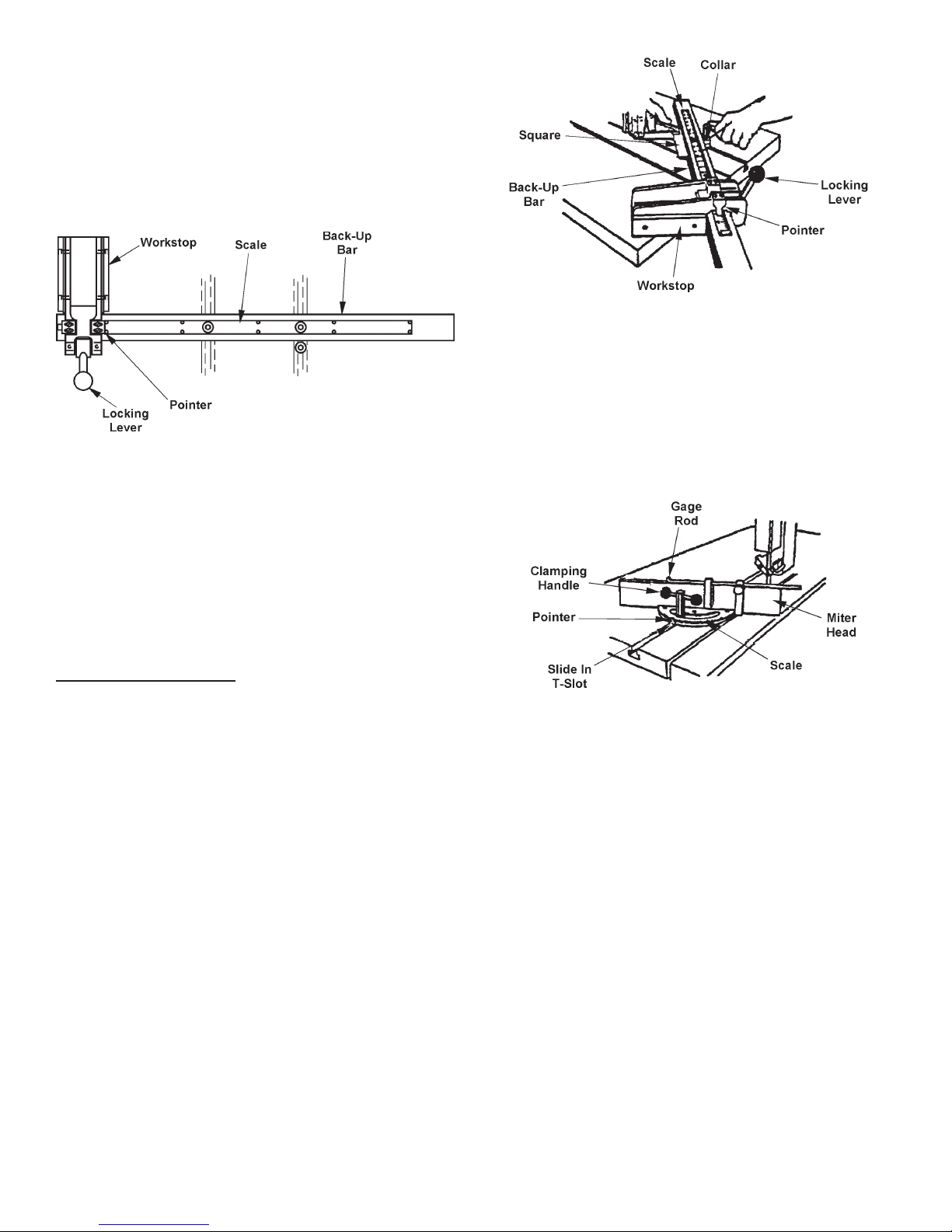
UNIVERSAL CALIBRATED WORK FIXTURE
(Used with Air Table Option)
Set-Up for Straight Cut-Off
1. Place the xture on the worktable at the required
distance from the saw band. Then: (a) Loosely
install T-nuts and screws; (b) If necessary, align
the scale's zero (0) mark with the saw band, then
"zero" the pointer.
2. Place socket head screws loosely in the T-nuts
projecting up from below the back-up bar. Then:
(a) Place the T-nuts in the worktable T-slots; (b)
Slide the work xture's back-up edge to a distance
equal to the desired length of cut. Be sure to allow
enough clearance for positioning the stock.
23
Page 28
UNIVERSAL CALIBRATED WORK FIXTURE
(Continued....)
3. Square the back-up bar to the worktable by aligning
one (1) movable workstop edge with the T-slot or
edge of the table sawing slot. Then: (a) Line up
the calibrated bar's "0" mark with the saw band; (b)
Tighten the socket head screws so that the back-up
bar is rmly anchored to the worktable.
Universal Calibrated Work Fixture Set-UP for Straight Cut-Off.
4. Shift the movable workstop to one side of the saw
band. Then: (a) Run the worktable forward until
the front of the workstop passes the saw band; (b)
Move the workstop toward the saw band until its
edge barely touches the set teeth.
Universal Calibrated Work Fixture Set-UP for Angle Cut-Off.
PROTRACTOR WORKSTOP & ALIGNMENT
GAGE (Used with Air Table Option)
1. To set up this unit: (a) Lock the slide bar into the
worktable T-slot so that the miter head clears the
saw band; (b) Release the clamping handle to
adjust the miter head for angle cutting between 0°
and 45°.
5. Close the locking lever to hold the workstop in
position. Then adjust the workstop pointer until it
lines up with the scale's "0" mark.
Set-Up for Angle Cut-Off
1. Loosen the left socket head screw. Next: (a)
Remove the right T-nut and screw from the back-up
bar; (b) Use a protractor or square to position the
back-up bar at the desired angle as measured to
the worktable's T-slot; (c) Tighten the socket head
screw.
2. Mount the collar on the right T-nut and fasten it to the
worktable (against the back-up bar) with the socket
head screw. Then: (a) Run the worktable forward
until the back-up bar barely touches the saw band;
(b) Set the workstop for the required stock length
dimension. The back-up bar scale is not used
for angle cuts.
3. Notch the back-up bar with the saw band to assure
being able to cut completely through the stock. Set
the worktable stop to limit travel to the length of
cut.
Protractor Workstop and Alignment Gage.
2. Adjust for the desired cut length by loosening the
gage rod thumb screw. Then: (a) Slide the rod to
the desired position; and (b) Tighten the thumb
screw.
DBW-15 BUTTWELDER
1. Information covering blade welding, plus operation
and maintenance of the optional DBW-15 Buttwelder
(with ash grinder and blade shear) are provided
in a seperate instruction manual included with the
machine.
OPTIONAL SAW GUIDES
1. It is possible to equip the machine with precision,
heavy-duty, high speed, insert-type saw guides or
roller saw guides.
24
Page 29

OPTIONAL SAW GUIDES (Continued....)
Roller Saw Guides
Insert-Type Saw Guides
• High speed, heavy-duty saw guide blocks are for
band speeds up to 6000 fpm (1830 m/min).
High Speed Saw Guides (Standard)
• Precision saw guide blocks are used for band
speeds up to 2000 fpm (610 m/min) with saw band
widths of 1/16 to 1/4 inch (1.5 to 6.3 mm).
1. Use roller saw guides for continuous high-speed
sawing. They are recommended for continuous
sawing at band speeds over 1300 fpm (390 m/
min).
• Type I roller saw guide blocks use 1/4 to 1/2 inch
(6 to 13 mm) saw bands and are for band speeds
up to 6000 fpm (1830 m/min).
Type I Roller Saw Guides.
Precision Saw Guides.
• Saw guides with steel or carbide-faced back-up
bearings with saw band widths of 1/16 to one
(1) inch (1.5 to 25.4 mm) can be used with this
machine.
• Type II roller saw guide blocks use 1/4 to one(1) inch
(6 to 25 mm) saw bands and are for band speeds
up to 6000 fpm (1830 m/min).
Type II roller saw guide blocks reduce the work
height capacity by one (1) inch (25 mm) and
restricts right table tilt to 27°.
Type II Roller Saw Guides.
Heavy-Duty Saw Guides W/Steel or Carbide-Faced Back-Up Bearings.
25
Page 30

OPTIONAL SAW GUIDES (Continued....)
ADJUSTABLE ANGLE SAW GUIDES
2. Roller saw guides are adjusted as follows:
• Select the rollers which match the width of saw band
to be used. Next: (a) Place one (1) back-up roller
(has a rear ange) and one (1) side roller in upper
guide block; (b) Place one (1) back-up roller and
one (1) side roller in the lower saw guide block in
opposite position of the upper guide; (c) Attach the
upper roller guide to the post and the lower roller
guide to the keeper block.
• Place the saw band over the upper and lower
bandwheels. Next: (a) Adjust the saw band tension;
(b) Loosen the roller lock screw; (c) Bring the
rollers toward the saw band by turning the eccentric
bearing shaft with a screwdriver. The rollers should
be just free enough to turn without moving the saw
band.
The bearings will overheat if the rollers are
too tight against the saw band. Conversely,
rollers that are too loose may cause the saw
band to wobble and affect cutting accuracy.
1. These saw guides allows to rotate the saw band a
set angle of 45° and 90° from the regular operating
position.
• Tighten the roller lock screws to prevent the
eccentric shaft from turning and changing the roller
adjustment.
90° SAW GUIDE BRACKETS
1. These brackets permit cutting materials longer than
the machine's regular throat capacity. Install the
upper and lower brackets as shown. Then the saw
guide blocks are mounted to the brackets.
90° Saw Guide Brackets.
2. When these brackets are used, be sure to: (a) Install
the correct size saw guides; (b) Install the saw band
so that it is twisted 90°; when it passes through the
saw guide inserts; (c) Operate the machine at band
speeds under 1500 fpm (450 m/min).
Adjustable Angle Saw Guides.
2. To adjust: (a) Pull the spring plunger out until it
disengages; (b) Turn the housing to the right until it
reaches the 45° preset stop until the spring plunger
snaps back into place: (c) Turn further to the right,
it will snap to the 90° preset stop. (d) Operate the
machine at band speeds under 1500 fpm (450m/
min).
DUST SPOUT
1. This option is located just below the worktable on
the right side of the machine frame near the lower
saw guide and attached to a collection system for
disposal of chips and other waste materials.
EXTRA WORK HEIGHT
1. The factory installed extra work height allows
maximum cutting capacity up to 30 inches (762.0
mm). Machines with this option have an auxiliary
post support, plus a slightly different frame weldment,
post guarding, and post elevating handwheel from
those shown elsewhere in this manual.
26
Page 31

BAND FILING
Bandlingoptionisusedonbandwheelswith
crowned rubber tires only.
1. There are standard and long le guides available.
Each set consists of a le guide back-up assembly,
plus 1/4 inch (6.3 mm), 3/8 inch (9.5 mm), and 1/2
inch (12.7 mm) guides.
Set-Up
1. Remove the saw band, saw guides, table center
plate, and post guard. Then: (a) Mount the le
guide back-up support to the lower keeper block;
(b) Install the upper le guide to the post.
File Guide Set-Up.
2. Lower the post until it will clear the stock thickness.
Post height above stock should be: (a) Not over
two (2) inches (50.8 mm) for a 1/4 inch (6.3 mm)
le band; (b) Not over four (4) inches (101.6 mm)
for 3/8 inch (9.5 mm) and 1/2 inch (12.7 mm) le
bands.
Longer le guides permit ling seven (7) inch (177.8
mm) thick stock with a 1/4 inch (6.3 mm) le band,
or eight (8) inch (203.2 mm) thick stock with 3/8
inch (9.5 mm) and 1/2 inch (12.7 mm) le bands.
3. Install the upper le guide and lock it rmly to the
post with the knurled thumbscrews. Insert the
special table center plate (round hole at the end of
its slot).
Joining File Band
Joining File Bands.
File Band Tracking and Tensioning
1. Adjust the upper bandwheel's tilt angle (if necessary)
so that the le band tracks on the center of the wheel
tire. Then: (a) Check to see that the le band is
in alignment and passing freely over the le guide
supports; (b) Apply the same tension as indicated
for a 1/8 inch (3.2 mm) wide carbon saw band.
Avoidexcessivelebandtensioning.
Internal Filing Set-Up
1. Release le band tension. Next: (a) Remove the
le band from around the bandwheels and separate
it by bending the joint to approximately 12 inches
(304.8 mm) radius.
2. Use your left forenger to depress the front end of
the yellow segment. Next: (a) Use your right thumb
and forenger to disengage the dowel; (b) Slide the
lock rivet to the slot's open end and remove it.
3. Run the le band through the stock and reassemble
it.Next: (a) Place the le band around the bandwheels;
(b) Apply tension and check alignment.
Filing Operation
1. Place the transmission gear shift lever in "low" range
before starting the saw band drive motor.
2. Keep these operating points in mind: (a) Keep
the les clean; (b) DO NOT le when the teeth
are loaded; (c) Filing can be performed without
coolant application if the layout lines will be easier
to follow.
1. Place the le band around the bandwheels and
insert one (1) end through the table center plate.
The band's cutting edges should point downward.
2. Hold the yellow lock rivet segment in your left hand.
Then: (a) Depress the spring steel band tip held in
the right hand; (b) Allow the rivet head to slip into
the slotted hole and slide into the slot's small end;
(c) Straighten the le band to allow the spring steel
end to snap over the dowel.
3. Clean the le band with a le card and coil it into
no more than three (3) loops before placing it in
storage.
27
Page 32

BAND POLISHING
Band polishing option is used on bandwheels
with crowned rubber tires only.
1. Three (3) polishing band grain cloths belts are
available in aluminum oxide:
Application Cutting Grit
Speeds
Grinding 50-300 fpm 50
(15-90 m/min)
Coarse 850-1000 fpm 80
Polishing (260-305 m/min)
Fine 850-15000 fpm 150
Polishing (260-450 m/min)
1. A laser devise is used to emit a line on the material
to be cut. This line shows the approximate spot
where the cut will take place.
2. The devise is controlled by a selector switch with
"ON" and "OFF" settings and is located on or near
the control panel. Turn the laser "OFF" when not
in use.
3. The laser is adjustable to position the laser beam
where desirable.
4. When the laser is turned on, a warm-up period of
3 to 5 seconds take place before a line appears. If
the line is difcult to see, darken the work area to
enhance the line.
Polishing Belt Recommendations.
Set-Up
1. Remove the table center plate. Next: (a) Mount
the polishing band's back-up support to the post
(replacing the saw guides); (b) Install the lower
adapter to the saw guide keeper block.
Polishing Guide Set-Up.
2. Lower the post to approximately four (4) inches
(101.6 mm) above the table. Then: (a) Mount and
track the polishing band in the same manner as le
bands; (b) Tension the polishing band in the same
manner as for a 1/16 inch (1.5 mm) wide carbon
saw band; (c) Install the special table center plate
(larger slot than the standard one).
5. Remove the protective shipping cap from the laser
devise before operation. Replace the protective
cap when not in use.
3. Occasionally rub graphite powder into the polishing
fabric to lubricate and increase band life. Use the
air nozzle to blow away dust while polishing.
DO NOT use coolant with the band polishing
option.
LASER LINE GENERATOR OPTION
To avoid eye damage, DO NOT stare into the
laser beam.
28
 Loading...