


D-Link DSR Series Router
User Manual
Copyright © 2010 TeamF1, Inc.
All rights reserved
Names mentioned are trademarks, registered trademarks or service marks of their respective
companies.
Part No.: TF1-DSR-1-0-0-UM-0002
1

TABLE OF CONTENTS
D-Link DSR Series Router
1. INTRODUCTION -------------------------------------------------------------------------------------------------- 5
1.1 About this User Manual -------------------------------------------------------------------------------------- 5
1.2 Typographical Conventions --------------------------------------------------------------------------------- 5
2. CONFIGURING YOUR NETWORK: LAN SETUP ---------------------------------------------------------- 7
2.1 LAN Configuration--------------------------------------------------------------------------------------------- 7
2.1.1 LAN Configuration in an IPv6 Network -------------------------------------------------------------- 10
2.1.2 Configuring IPv6 Router Advertisements ----------------------------------------------------------- 13
2.2 VLAN Configuration ----------------------------------------------------------------------------------------- 16
2.2.1 Associating VLANs to ports --------------------------------------------------------------------------- 18
2.3 Configurable Port: DMZ Setup --------------------------------------------------------------------------- 20
2.4 Universal Plug and Play (UPnP) ------------------------------------------------------------------------- 21
3. CONNECTING TO THE INTERNET: WAN SETUP ------------------------------------------------------ 24
3.1 Internet Setup Wizard -------------------------------------------------------------------------------------- 24
3.2 WAN Configuration ----------------------------------------------------------------------------------------- 25
WAN Port IP address ---------------------------------------------------------------------------------------------- 26
WAN DNS Servers -------------------------------------------------------------------------------------------------- 26
DHCP WAN ---------------------------------------------------------------------------------------------------------- 27
3.2.1 PPPoE Profiles ------------------------------------------------------------------------------------------- 29
3.2.2 WAN Configuration in an IPv6 Network ------------------------------------------------------------- 30
3.2.3 Checking WAN Status ---------------------------------------------------------------------------------- 32
3.3 Bandwidth Controls ----------------------------------------------------------------------------------------- 34
3.4 Features with Multiple WAN Links ----------------------------------------------------------------------- 37
3.4.1 Auto Failover --------------------------------------------------------------------------------------------- 37
3.4.2 Load Balancing ------------------------------------------------------------------------------------------ 38
3.4.3 Protocol Bindings ---------------------------------------------------------------------------------------- 39
3.5 Routing Configuration -------------------------------------------------------------------------------------- 40
3.5.1 Routing Mode -------------------------------------------------------------------------------------------- 40
3.5.2 Dynamic Routing (RIP) --------------------------------------------------------------------------------- 42
3.5.3 Static Routing -------------------------------------------------------------------------------------------- 44
3.6 Configurable Port - WAN Option ------------------------------------------------------------------------- 45
3.7 WAN Port Settings ------------------------------------------------------------------------------------------ 47
2
4. WIRELESS ACCESS POINT SETUP ----------------------------------------------------------------------- 50
4.1 Wireless Settings Wizard ---------------------------------------------------------------------------------- 50
4.1.1 Wireless Network Setup Wizard ---------------------------------------------------------------------- 51
4.1.2 Add Wireless Device with WPS ----------------------------------------------------------------------- 52
4.1.3 Manual Wireless Network Setup --------------------------------------------------------------------- 52
4.2 Wireless Profiles -------------------------------------------------------------------------------------------- 52
4.2.1 WEP Security --------------------------------------------------------------------------------------------- 54
4.2.2 WPA or WPA2 with PSK ------------------------------------------------------------------------------- 55
4.2.3 RADIUS Authentication -------------------------------------------------------------------------------- 56
4.3 Creating and Using Access Points ---------------------------------------------------------------------- 57
4.3.1 Primary benefits of Virtual APs: ---------------------------------------------------------------------- 59
4.4 Tuning Radio Specific Settings --------------------------------------------------------------------------- 60
4.5 Advanced Wireless Settings ------------------------------------------------------------------------------ 61
4.6 Wi-Fi Protected Setup (WPS) ----------------------------------------------------------------------------- 62
5. SECURING THE PRIVATE NETWORK -------------------------------------------------------------------- 65

User Manual
5.1 Firewall Rules ------------------------------------------------------------------------------------------------ 65
5.2 Defining Rule Schedules ---------------------------------------------------------------------------------- 67
5.3 Configuring Firewall Rules -------------------------------------------------------------------------------- 68
5.3.1 Firewall Rule Configuration Examples -------------------------------------------------------------- 73
5.4 Security on Custom Services ----------------------------------------------------------------------------- 78
5.5 ALG support -------------------------------------------------------------------------------------------------- 79
5.6 VPN Passthrough for Firewall ---------------------------------------------------------------------------- 80
5.7 Application Rules -------------------------------------------------------------------------------------------- 81
5.8 Web Content Filtering -------------------------------------------------------------------------------------- 82
5.9 IP/MAC Binding ---------------------------------------------------------------------------------------------- 85
5.10 Intrusion Prevention (IPS) --------------------------------------------------------------------------------- 86
5.10.1 Protecting from Internet Attacks ---------------------------------------------------------------------- 87
6. IPSEC VPN ------------------------------------------------------------------------------------------------------- 89
6.1 VPN Wizard --------------------------------------------------------------------------------------------------- 89
6.2 Configuring IKE Policies ----------------------------------------------------------------------------------- 92
6.2.1 Configuring an IKE Policy using XAUTH ----------------------------------------------------------- 95
6.3 Configuring VPN Policies ---------------------------------------------------------------------------------- 95
6.4 Configuring VPN clients ----------------------------------------------------------------------------------- 97
6.5 PPTP / L2TP Tunnels -------------------------------------------------------------------------------------- 98
6.5.1 PPTP Tunnel Support ---------------------------------------------------------------------------------- 98
6.5.2 L2TP Tunnel Support ----------------------------------------------------------------------------------- 98
7. SSL VPN -------------------------------------------------------------------------------------------------------- 101
7.1 Users, Groups, and Domains --------------------------------------------------------------------------- 102
7.1.1 User Types and Passwords ------------------------------------------------------------------------- 103
7.2 Using SSL VPN Policies --------------------------------------------------------------------------------- 104
7.2.1 Using Network Resources --------------------------------------------------------------------------- 107
7.3 Application Port Forwarding ---------------------------------------------------------------------------- 108
7.4 SSL VPN Client Configuration -------------------------------------------------------------------------- 110
7.5 User Portal -------------------------------------------------------------------------------------------------- 112
7.5.1 Creating Portal Layouts ------------------------------------------------------------------------------ 113
8. ADVANCED CONFIGURATION TOOLS ----------------------------------------------------------------- 115
8.1 USB Device Setup ---------------------------------------------------------------------------------------- 115
8.2 Authentication Certificates ------------------------------------------------------------------------------ 115
9. ADMINISTRATION & MANAGEMENT ------------------------------------------------------------------- 117
9.1 Configuration Access Control --------------------------------------------------------------------------- 117
9.1.1 Remote Management --------------------------------------------------------------------------------- 117
9.1.2 CLI Access ---------------------------------------------------------------------------------------------- 118
9.2 SNMP Configuration -------------------------------------------------------------------------------------- 118
9.3 Configuring Time Zone and NTP ----------------------------------------------------------------------- 120
9.4 Backing up and Restoring Configuration Settings -------------------------------------------------- 121
9.5 Upgrading Router Firmware ----------------------------------------------------------------------------- 123
9.6 Dynamic DNS Setup -------------------------------------------------------------------------------------- 124
9.7 Using Diagnostic Tools ---------------------------------------------------------------------------------- 125
9.7.1 Ping ------------------------------------------------------------------------------------------------------- 126
9.7.2 Trace Route -------------------------------------------------------------------------------------------- 126
3

D-Link DSR Series Router
9.7.3 DNS Lookup -------------------------------------------------------------------------------------------- 127
9.7.4 Router Options ----------------------------------------------------------------------------------------- 127
10. ROUTER STATUS AND STATISTICS ---------------------------------------------------------------- 128
10.1 System Overview ------------------------------------------------------------------------------------------ 128
10.1.1 Device Status ------------------------------------------------------------------------------------------ 128
10.1.2 Resource Utilization ---------------------------------------------------------------------------------- 130
10.2 Traffic Statistics ------------------------------------------------------------------------------------------- 132
10.2.1 Wired Port Statistics ---------------------------------------------------------------------------------- 132
10.2.2 Wireless Statistics ------------------------------------------------------------------------------------- 133
10.3 Active Connections --------------------------------------------------------------------------------------- 134
10.3.1 Sessions through the Router ------------------------------------------------------------------------ 134
10.3.2 Wireless Clients ---------------------------------------------------------------------------------------- 135
10.3.3 LAN Clients --------------------------------------------------------------------------------------------- 135
10.3.4 Active VPN Tunnels ----------------------------------------------------------------------------------- 136
11. TROUBLE SHOOTING ---------------------------------------------------------------------------------- 138
11.1 Internet connection --------------------------------------------------------------------------------------- 138
11.2 Date and time ---------------------------------------------------------------------------------------------- 140
11.3 Pinging to Test LAN Connectivity ---------------------------------------------------------------------- 141
11.3.1 Testing the LAN path from your PC to your router --------------------------------------------- 141
11.3.2 Testing the LAN path from your PC to a remote device --------------------------------------- 142
11.4 Restoring factory-default configuration settings ---------------------------------------------------- 143
12. CREDITS --------------------------------------------------------------------------------------------------- 145
APPENDIX A. GLOSSARY ----------------------------------------------------------------------------------- 146
APPENDIX B. FACTORY DEFAULT SETTINGS -------------------------------------------------------- 149
APPENDIX C. STANDARD SERVICES AVAILABLE FOR PORT FORWARDING & FIREWALL
CONFIGURATION ------------------------------------------------------------------------------------------------ 151
4

User Manual
1. Introduction
The D-Link DSR series of routers are enterprise grade security gateway solutions
with Firewall, VPN and in some cases 802.11n Access Point capabilities. These
devices have wizards to allow for quick and easy configuration for internet access,
VPN tunnels, and wireless networks. The GUI provides all the capabilities for
novice and advanced users to administer this secure and feature rich router.
1.1 About this User Manual
This document is a high level manual to allow new D-Link DSR Series Router
users to configure connectivity, setup VPN tunnels, establish firewall rules
and perform general administrative tasks. Typical deployment and use case
scenarios are described in each section. For more detailed setup instructions
and explanations of each configuration parameter, refer to the online help that
can be accessed from each page in the router GUI.
1.2 Typographical Conventions
The following is a list of the various terms, followed by an example of how that
term is represented in this document:
Product Name – D-Link DSR-1000 / DSR-1000N / DSR-500 / DSR-500N
GUI Menu Path/GUI Navigation – Monitoring > Router Status
User input – Text
Important note –
5


2. Configuring Your Network: LAN Setup
It is assumed that the user has a machine for management connected to the LAN
to the router. The LAN connection may be through the wired Ethernet ports
available on the router, or once the initial setup is complete, the device may also
be managed through its wireless interface as it is bridged with the LAN. Access
the router’s graphical user interface (GUI) for management by using any web
browser, such as Microsoft Internet Explorer or Mozilla Firefox:
Go to http://192.168.10.1 (default IP address) to display the router’s
management login screen.
Default login credentials for the management GUI:
Username: admin
Password: admin
If the router’s LAN IP address was changed, use that IP address in the
navigation bar of the browser to access the router’s management UI.
2.1 LAN Configuration
Setup > Network Settings > LAN Configuration
By default, the router functions as a Dynamic Host Configuration Protocol
(DHCP) server to the hosts on the WLAN or LAN network. With DHCP, PCs
and other LAN devices can be assigned IP addresses as well as addresses
for DNS servers, Windows Internet Name Service (WINS) servers, and the
default gateway. With the DHCP server enabled the router’s IP address
serves as the gateway address for LAN and WLAN clients. The PCs in the
LAN are assigned IP addresses from a pool of addresses specified in this
procedure. Each pool address is tested before it is assigned to avoid
duplicate addresses on the LAN.
For most applications the default DHCP and TCP/IP settings are satisfactory.
If you want another PC on your network to be the DHCP server or if you are
manually configuring the network settings of all of your PCs, set the DHCP
7

D-Link DSR Series Router
mode to ‘none’. DHCP relay can be used to forward DHCP lease information
from another LAN device that is the network’s DHCP server; this is
particularly useful for wireless clients.
Instead of using a DNS server, you can use a Windows Internet Naming
Service (WINS) server. A WINS server is the equivalent of a DNS server but
uses the NetBIOS protocol to resolve hostnames. The router includes the
WINS server IP address in the DHCP configuration when acknowledging a
DHCP request from a DHCP client.
You can also enable DNS proxy for the LAN. When this is enabled the router
then as a proxy for all DNS requests and communicates with the ISP’s DNS
servers. When disabled all DHCP clients receive the DNS IP addresses of the
ISP.
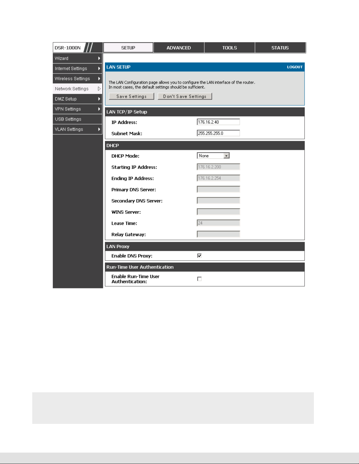
To configure LAN Connectivity, please follow the steps below:
1.
In the LAN Setup page, enter the following information for your router:
IP address (factory default: 192.168.10.1).
If you change the IP address and click Save Settings, the GUI will not
respond. Open a new connection to the new IP address and log in again. Be
sure the LAN host (the machine used to manage the router) has obtained IP
address from newly assigned pool (or has a static IP address in the router’s
LAN subnet) before accessing the router via changed IP address.
Subnet mask (factory default: 255.255.255.0).
8
2.
In the DHCP section, select the DHCP mode:
None: the router’s DHCP server is disabled for the LAN
DHCP Server. With this option the router assigns an IP address within the
specified range plus additional specified information to any LAN device that
requests DHCP served addresses.

User Manual
DHCP Relay: With this option enabled, DHCP clients on the LAN can receive IP
If DHCP is being enabled, enter the following DHCP server parameters:
address leases and corresponding information from a DHCP server on a
different subnet. Specify the Relay Gateway, and when LAN clients make a
DHCP request it will be passed along to the server accessible via the Relay
Gateway IP address.
• Starting and Ending IP Addresses: Enter the first and last continuous
addresses in the IP address pool. Any new DHCP client joining the LAN is
assigned an IP address in this range. The default starting address is
192.168.10.2. The default ending address is 192.168.10.100. These
addresses should be in the same IP address subnet as the router’s LAN
IP address. You may wish to save part of the subnet range for devices
with statically assigned IP addresses in the LAN.
• Primary and Secondary DNS servers: If configured domain name system
(DNS) servers are available on the LAN enter their IP addresses here.
• WINS Server (optional): Enter the IP address for the WINS server or, if
present in your network, the Windows NetBios server.
• Lease Time: Enter the time, in hours, for which IP addresses are leased to
clients.
Enable DNS Proxy: To enable the router to act as a proxy for all DNS requests
and communicate with the ISP’s DNS servers, click the checkbox.
3.
Click Save Settings to apply all changes.
9
D-Link DSR Series Router
Figure 1: Setup page for LAN TCP/IP settings
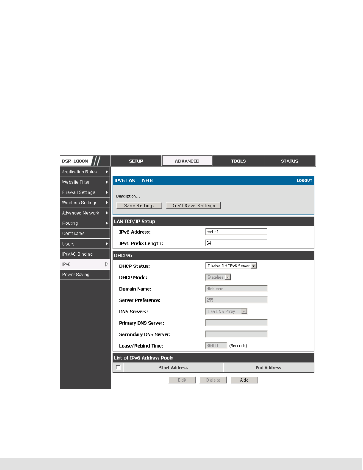
2.1.1
LAN Configuration in an IPv6 Network
Advanced > IPv6 > IPv6 LAN > IPv6 LAN Config
In IPv6 mode, the LAN DHCP server is enabled by default (similar to IPv4
mode). The DHCPv6 server will serve IPv6 addresses from configured
address pools with the IPv6 Prefix Length assigned to the LAN.
IPv4 / IPv6 mode must be enabled in the Advanced > IPv6 > IP mode to
enable IPv6 configuration options.
10
User Manual
2.1.1.1 LAN Settings
The default IPv6 LAN address for the router is fec0::1. You can change this
128 bit IPv6 address based on your network requirements. The other field
that defines the LAN settings for the router is the prefix length. The IPv6
network (subnet) is identified by the initial bits of the address called the
prefix. By default this is 64 bits long. All hosts in the network have common
initial bits for their IPv6 address; the number of common initial bits in the
network’s addresses is set by the prefix length field.
Figure 2: IPv6 LAN and DHCPv6 configuration
11

D-Link DSR Series Router
If you change the IP address and click Save Settings, the GUI will not
respond. Open a new connection to the new IP address and log in again. Be
sure the LAN host (the machine used to manage the router) has obtained IP
address from newly assigned pool (or has a static IP address in the router’s
LAN subnet) before accessing the router via changed IP address.
As with an IPv4 LAN network, the router has a DHCPv6 server. If enabled,
the router assigns an IP address within the specified range plus additional
specified information to any LAN PC that requests DHCP served addresses.
The following settings are used to configure the DHCPv6 server:
DHCP Mode: The IPv6 DHCP server is either stateless or stateful. If stateless
is selected an external IPv6 DHCP server is not required as the IPv6 LAN
hosts are auto-configured by this router. In this case the router advertisement
daemon (RADVD) must be configured on this device and ICMPv6 router
discovery messages are used by the host for auto-configuration. There are no
managed addresses to serve the LAN nodes. If stateful is selected the IPv6
LAN host will rely on an external DHCPv6 server to provide required
configuration settings
The domain name of the DHCPv6 server is an optional setting
Server Preference is used to indicate the preference level of this DHCP server.
DHCP advertise messages with the highest server preference value to a LAN
host are preferred over other DHCP server advertise messages. The default
is 255.
12
The DNS server details can be manually entered here (primary/secondary
options. An alternative is to allow the LAN DHCP client to receive the DNS
server details from the ISP directly. By selecting Use DNS proxy, this router
acts as a proxy for all DNS requests and communicate with the ISP’s DNS
servers (a WAN configuration parameter).

User Manual
Primary and Secondary DNS servers: If there are configured domain name
system (DNS) servers available on the LAN enter the IP addresses here.
Lease/Rebind time sets the duration of the DHCPv6 lease from this router to
the LAN client.
2.1.1.2 IPv6 Address Pools
This feature allows you to define the IPv6 delegation prefix for a range of IP
addresses to be served by the gateway’s DHCPv6 server. Using a
delegation prefix you can automate the process of informing other
networking equipment on the LAN of DHCP information specific for the
assigned prefix.
2.1.2
Configuring IPv6 Router Advertisements
Router Advertisements are analogous to IPv4 DHCP assignments for LAN
clients, in that the router will assign an IP address and supporting network
information to devices that are configured to accept such details. Router
Advertisement is required in an IPv6 network is required for stateless auto
configuration of the IPv6 LAN. By configuring the Router Advertisement
Daemon on this router, the device will listen on the LAN for router
solicitations and respond to these LAN hosts with router advisements.
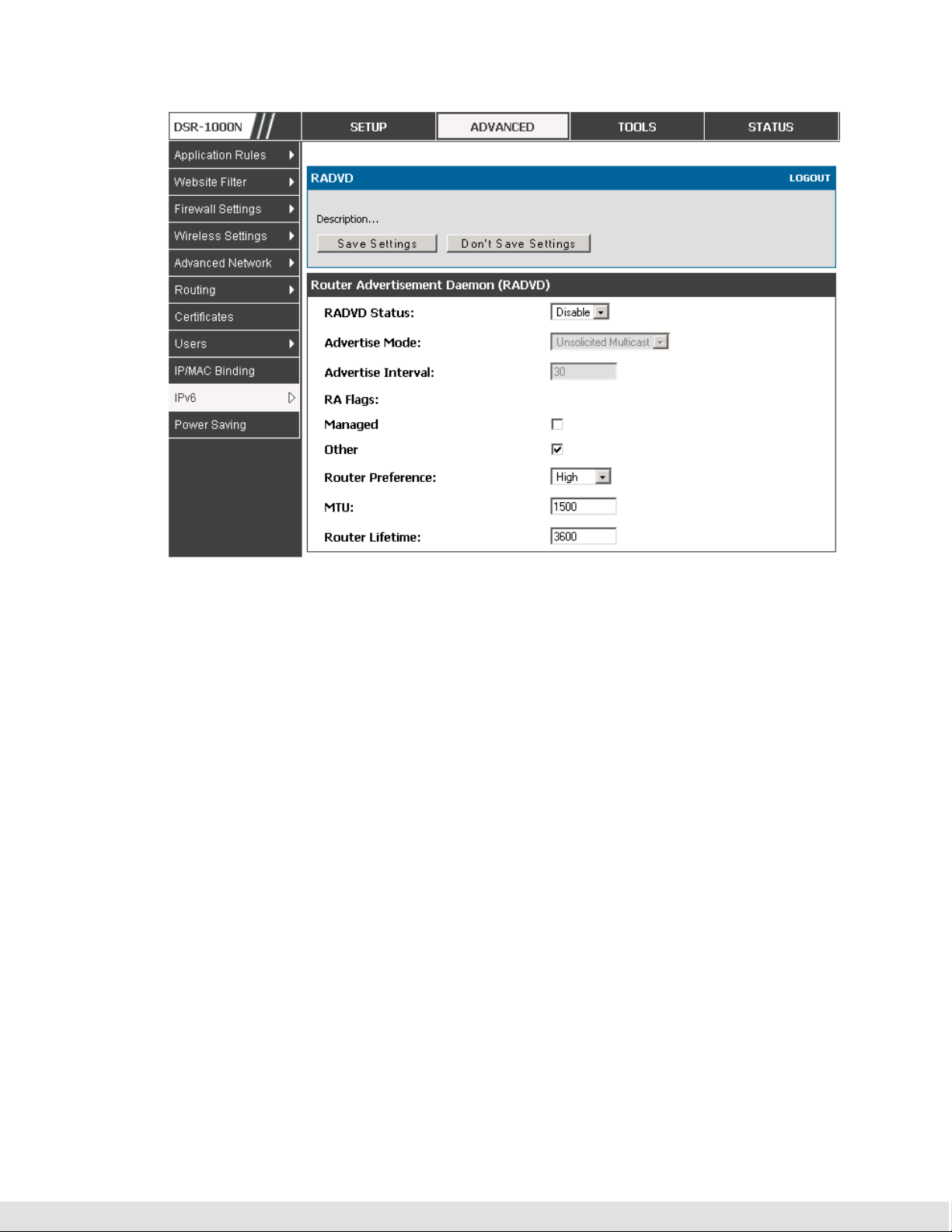
2.1.2.1 RADVD
Advanced > IPv6 > IPv6 LAN > Router Advertisement
To support stateless IPv6 auto configuration on the LAN, set the RADVD
status to Enable. The following settings are used to configure RADVD:
Advertise Mode: Select Unsolicited Multicast to send router advertisements
(RA’s) to all interfaces in the multicast group. To restrict RA’s to well known
IPv6 addresses on the LAN, and thereby reduce overall network traffic, select
Unicast only.
13

D-Link DSR Series Router
Advertise Interval: When advertisements are unsolicited multicast packets, this
interval sets the maximum time between advertisements from the interface.
The actual duration between advertisements is a random value between one
third of this field and this field. The default is 30 seconds.
RA Flags: The router advertisements (RA’s) can be sent with one or both of
these flags. Chose Managed to use the administered /stateful protocol for
address auto configuration. If the Other flag is selected the host uses
administered/stateful protocol for non-address auto configuration.
Router Preference: this low/medium/high parameter determines the preference
associated with the RADVD process of the router. This is useful if there are
other RADVD enabled devices on the LAN as it helps avoid conflicts for IPv6
clients.
MTU: The router advertisement will set this maximum transmission unit (MTU)
value for all nodes in the LAN that are autoconfigured by the router. The
default is 1500.
Router Lifetime: This value is present in RA’s and indicates the usefulness of
this router as a default router for the interface. The default is 3600 seconds.
Upon expiration of this value, a new RADVD exchange must take place
between the host and this router.
14
User Manual
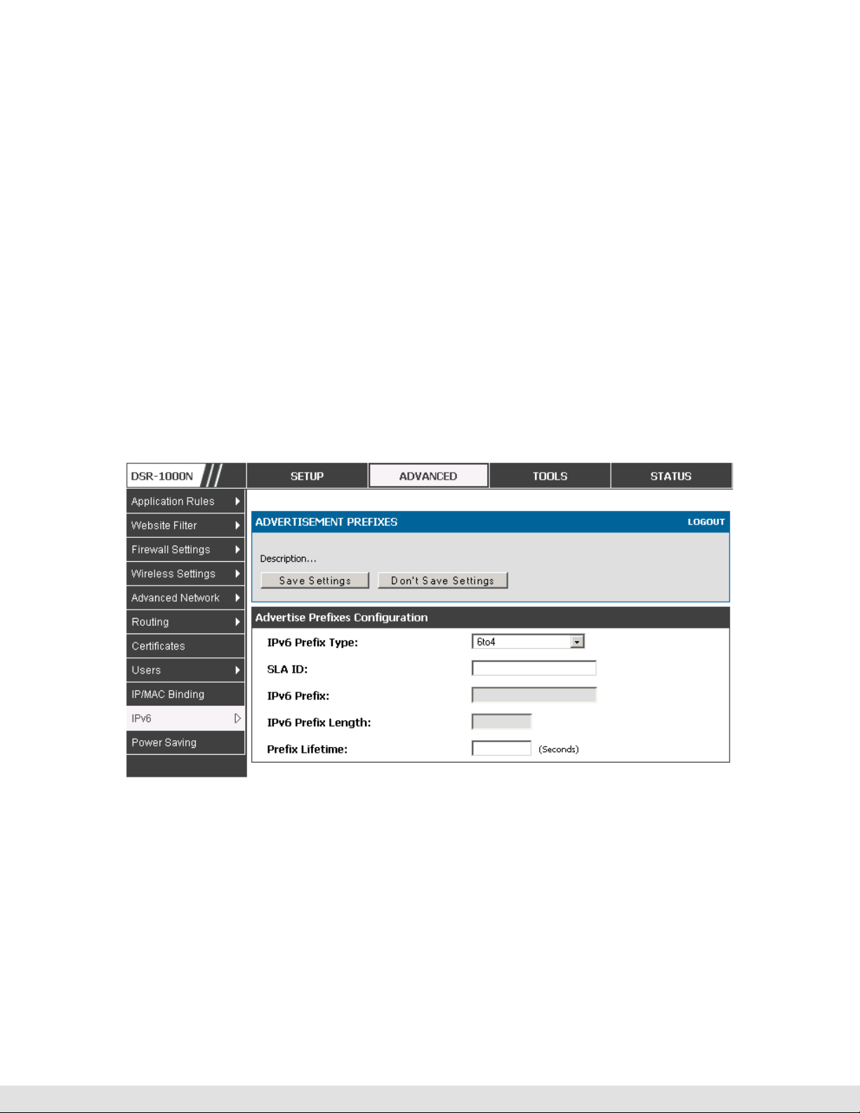
2.1.2.2
Figure 3: Configuring the Router Advertisement Daemon
Advertisement Prefixes
Advanced > IPv6 > IPv6 LAN > Advertisement Prefixes
The router advertisements configured with advertisement prefixes allow this
router to inform hosts how to perform stateless address autoconfiguration.
Router advertisements contain a list of subnet prefixes that allow the router
to determine neighbors and whether the host is on the same link as the
router.
The following prefix options are available for the router advertisements:
IPv6 Prefix Type: To ensure hosts support IPv6 to IPv4 tunnel select the 6to4
prefix type. Selecting Global/Local/ISATAP will allow the nodes to support all
other IPv6 routing options
15
D-Link DSR Series Router
SLA ID: The SLA ID (Site-Level Aggregation Identifier) is available when 6to4
Prefixes are selected. This should be the interface ID of the router’s LAN
interface used for router advertisements.
IPv6 Prefix: When using Global/Local/ISATAP prefixes, this field is used to
define the IPv6 network advertised by this router.
IPv6 Prefix Length: This value indicates the number contiguous, higher order
bits of the IPv6 address that define up the network portion of the address.
Typically this is 64.
Prefix Lifetime: This defines the duration (in seconds) that the requesting node
is allowed to use the advertised prefix. It is analogous to DHCP lease time in
an IPv4 network.
16
Figure 4: IPv6 Advertisement Prefix settings
2.2 VLAN Configuration
The router supports virtual network isolation on the LAN with the use of
VLANs. LAN devices can be configured to communicate in a subnetwork
defined by VLAN identifiers. LAN ports can be assigned unique VLAN IDs so
that traffic to and from that physical port can be isolated from the general
User Manual
LAN. VLAN filtering is particularly useful to limit broadcast packets of a
device in a large network
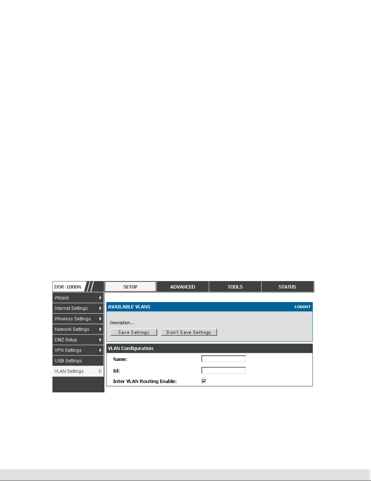
VLAN support is disabled by default in the router. In the VLAN Configuration
page, enable VLAN support on the router and then proceed to the next
section to define the virtual network.
Setup > VLAN Settings > Available VLAN
The Available VLAN page shows a list of configured VLANs by name and
VLAN ID. A VLAN membership can be created by clicking the Add button
below the List of Available VLANs.
A VLAN membership entry consists of a VLAN identifier and the numerical
VLAN ID which is assigned to the VLAN membership. The VLAN ID value can
be any number from 2 to 4091. VLAN ID 1 is reserved for the default VLAN,
which is used for untagged frames received on the interface. VLAN IDs 4092
is reserved and cannot be used. By enabling Inter VLAN Routing, you will
allow traffic from LAN hosts belonging to this VLAN ID to pass through to
other configured VLAN IDs that have Inter VLAN Routing enabled.
Figure 5: Adding VLAN memberships to the LAN
17
D-Link DSR Series Router
2.2.1
Associating VLANs to ports
In order to tag all traffic through a specific LAN port with a VLAN ID, you can
associate a VLAN to a physical port.
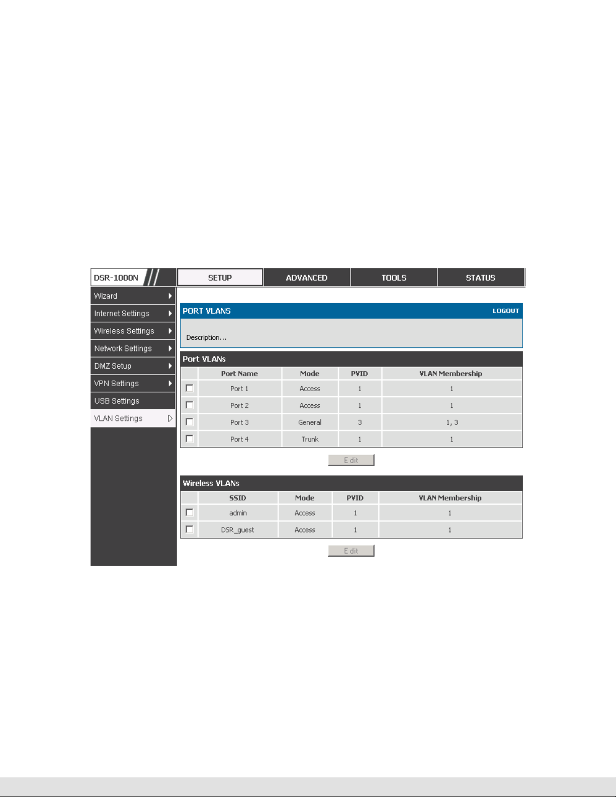
Setup > VLAN Settings > Port VLAN
VLAN membership properties for the LAN and wireless LAN are listed on this
page. The VLAN Port table displays the port identifier, the mode setting for
that port and VLAN membership information. The configuration page is
accessed by selecting one of the four physical ports or a configured access
point and clicking Edit.
Figure 6: Port VLAN list
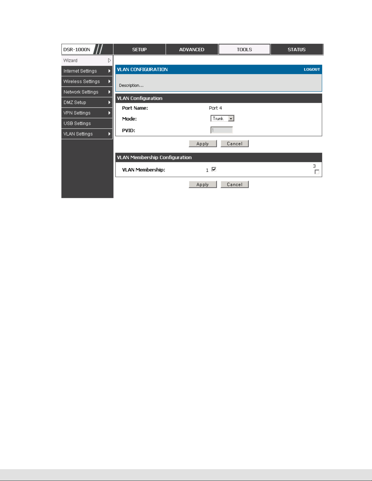
The edit page offers the following configuration options:
Mode: The mode of this VLAN can be General, Access, or Trunk. The default
is access.
18

User Manual
In General mode the port is a member of a user selectable set of VLANs.
The port sends and receives data that is tagged or untagged with a VLAN
ID. If the data into the port is untagged, it is assigned the defined PVID. In
the configuration from Figure 4, Port 3 is a General port with PVID 3, so
untagged data into Port 3 will be assigned PVID 3. All tagged data sent
out of the port with the same PVID will be untagged. This is mode is
typically used with IP Phones that have dual Ethernet ports. Data coming
from phone to the switch port on the router will be tagged. Data passing
through the phone from a connected device will be untagged.
In Access mode the port is a member of a single VLAN (and only one). All
data going into and out of the port is untagged. Traffic through a port in
access mode looks like any other Ethernet frame.
In Trunk mode the port is a member of a user selectable set of VLANs. All
data going into and out of the port is tagged. Untagged coming into the port
is not forwarded, except for the default VLAN with PVID=1, which is
untagged. Trunk ports multiplex traffic for multiple VLANs over the same
physical link.
Select PVID for the port when the General mode is selected.
Configured VLAN memberships will be displayed on the VLAN Membership
Configuration for the port. By selecting one more VLAN membership options
for a General or Trunk port, traffic can be routed between the selected VLAN
membership IDs
19
D-Link DSR Series Router
Figure 7: Configuring VLAN membership for a port
2.3 Configurable Port: DMZ Setup
This router supports one of the physical ports to be configured as a secondary
WAN Ethernet port or a dedicated DMZ port. A DMZ is a subnetwork that is
open to the public but behind the firewall. The DMZ adds an additional layer
of security to the LAN, as specific services/ports that are exposed to the
internet on the DMZ do not have to be exposed on the LAN. It is
recommended that hosts that must be exposed to the internet (such as web or
email servers) be placed in the DMZ network. Firewall rules can be allowed
to permit access specific services/ports to the DMZ from both the LAN or
WAN. In the event of an attack to any of the DMZ nodes, the LAN is not
necessarily vulnerable as well.
20
Setup > DMZ Setup > DMZ Setup Configuration
DMZ configuration is identical to the LAN configuration. There are no
restrictions on the IP address or subnet assigned to the DMZ port, other than
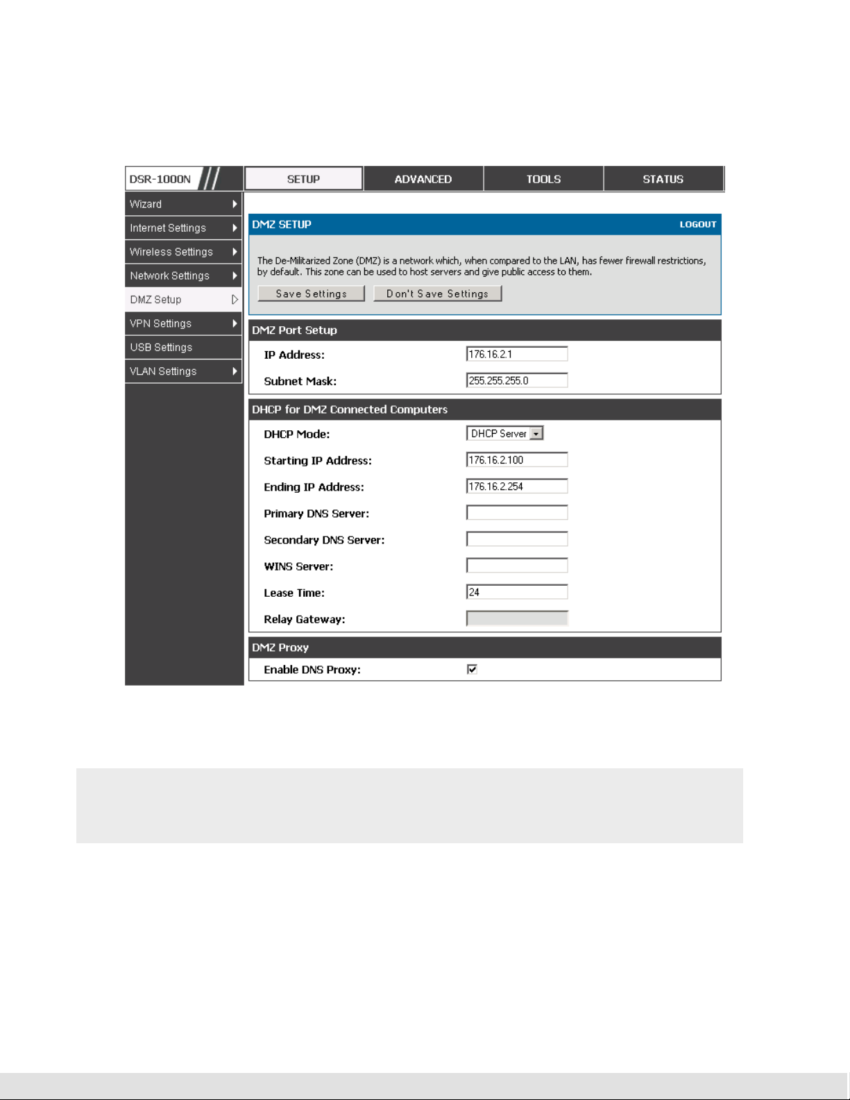
User Manual
the fact that it cannot be identical to the IP address given to the LAN interface
of this gateway.
Figure 8: DMZ configuration
In order to configure a DMZ port, the router’s configurable port must be set
to DMZ in the Setup > Internet Settings > Configurable Port page.
2.4 Universal Plug and Play (UPnP)
Advanced > Advanced Network > UPnP
21
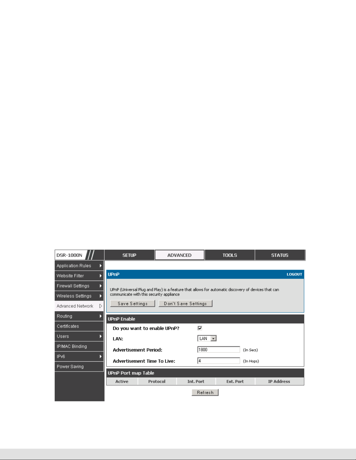
D-Link DSR Series Router
Universal Plug and Play (UPnP) is a feature that allows the router to
discovery devices on the network that can communicate with the router and
allow for auto configuration. If a network device is detected by UPnP, the
router can open internal or external ports for the traffic protocol required by
that network device.
Once UPnP is enabled, you can configure the router to detect UPnPsupporting devices on the LAN (or a configured VLAN). If disabled, the
router will not allow for automatic device configuration.
Configure the following settings to use UPnP:
Advertisement Period: This is the frequency that the router broadcasts UPnP
information over the network. A large value will minimize network traffic but
cause delays in identifying new UPnP devices to the network.
Advertisement Time to Live: This is expressed in hops for each UPnP packet.
This is the number of steps a packet is allowed to propagate before being
discarded. Small values will limit the UPnP broadcast range. A default of 4 is
typical for networks with few switches.
22

User Manual
UPnP Port map Table
The UPnP Port map Table has the details of UPnP devices that respond to
the router’s advertisements. The following information is displayed for each
detected device:
Active: A yes/no indicating whether the port of the UPnP device that established
Protocol: The network protocol (i.e. HTTP, FTP, etc.) used by the device
Int. Port (Internal Port): The internal ports opened by UPnP (if any)
Figure 9: UPnP Configuration
a connection is currently active
Ext. Port (External Port): The external ports opened by UPnP (if any)
IP Address: The IP address of the UPnP device detected by this router
Click Refresh to refresh the portmap table and search for any new UPnP
devices.
23
D-Link DSR Series Router
3. Connecting to the Internet: WAN Setup
This router has two WAN ports that can be used to establish a connection to the
internet. The following ISP connection types are supported: DHCP, Static, PPPoE,
PPTP, L2TP, 3G Internet (via USB modem).
It is assumed that you have arranged for internet service with your Internet Service
Provider (ISP). Please contact your ISP or network administrator for the
configuration information that will be required to setup the router.
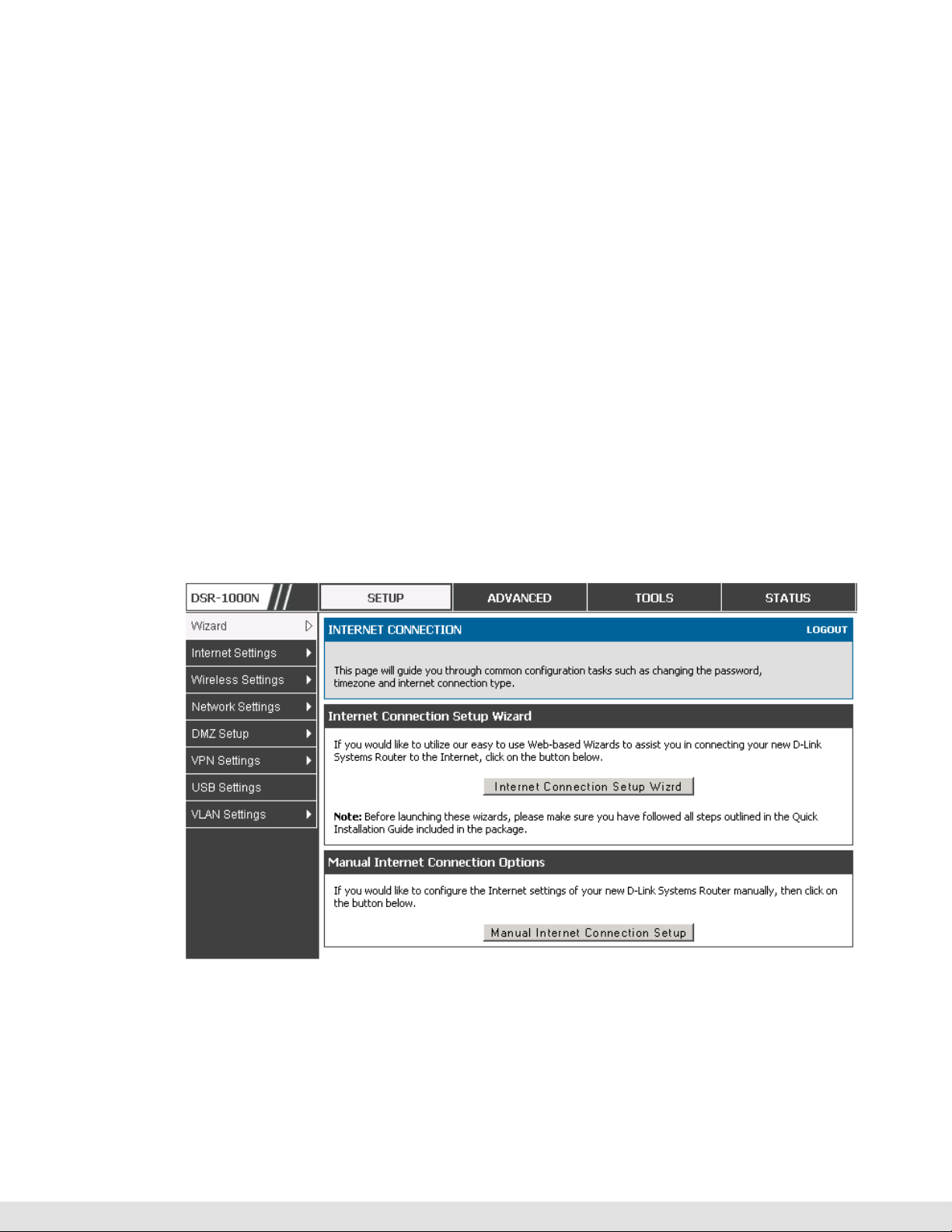
3.1 Internet Setup Wizard
Setup > Wizard > Internet
The Internet Connection Setup Wizard is available for users new to
networking. By going through a few straightforward configuration pages you
can take the information provided by your ISP to get your WAN connection up
and enable internet access for your network.
Figure 10: Internet Connection Setup Wizard
You can start using the Wizard by logging in with the administrator password
for the router. Once authenticated set the time zone that you are located in,
24

User Manual
and then choose the type of ISP connection type: DHCP, Static, PPPoE,
PPTP, L2TP. Depending on the connection type a username/password may
be required to register this router with the ISP. In most cases the default
settings can be used if the ISP did not specify that parameter. The last step
in the Wizard is to click the Connect button, which confirms the settings by
establishing a link with the ISP. Once connected, you can move on and
configure other features in this router.
3G Internet access with a USB modem is supported on the secondary WAN
port (WAN2). The Internet Connection Setup Wizard assists with the
primary WAN port (WAN1) configuration only.
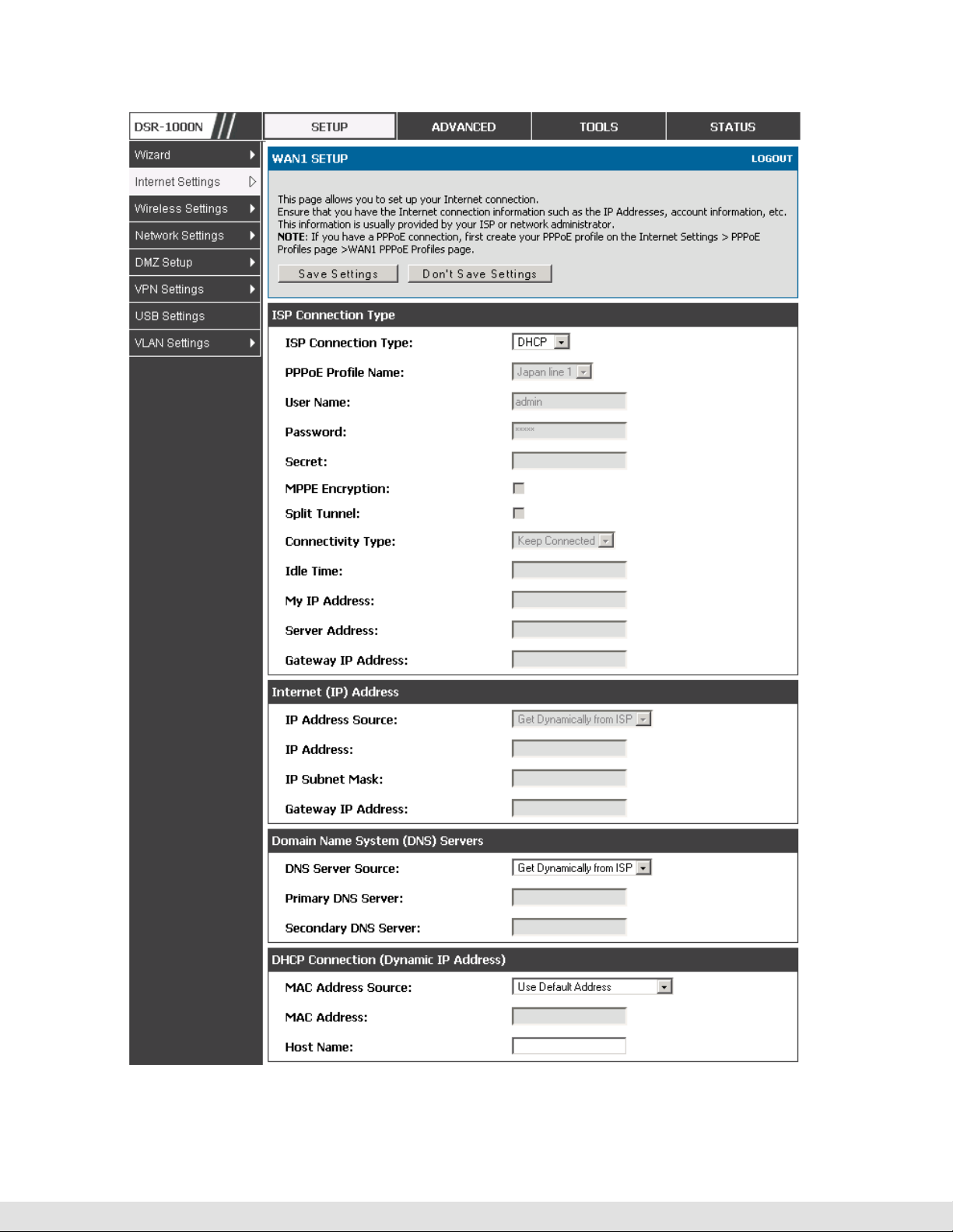
3.2 WAN Configuration
Setup > Internet Settings > WAN1 Setup
You must either allow the router to detect WAN connection type automatically
or configure manually the following basic settings to enable Internet
connectivity:
ISP Connection type: Based on the ISP you have selected for the primary
WAN link for this router, choose Static IP address, DHCP client, Point-toPoint Tunneling Protocol (PPTP), Point-to-Point Protocol over Ethernet
(PPPoE), Layer 2 Tunneling Protocol (L2TP). Required fields for the selected
ISP type become highlighted. Enter the following information as needed and
as provided by your ISP:
PPPoE Profile Name. This menu lists configured PPPoE profiles, particularly
useful when configuring multiple PPPoE connections (i.e. for Japan ISPs that
have multiple PPPoE support).
ISP login information. This is required for PPTP and L2TP ISPs.
User Name
Password
Secret (required for L2TP only)
25

D-Link DSR Series Router
MPPE Encryption: For PPTP links, your ISP may require you to enable
Microsoft Point-to-Point Encryption (MPPE).
Split Tunnel (supported for PPTP and L2TP connection). This setting allows
your LAN hosts to access internet sites over this WAN link while still
permitting VPN traffic to be directed to a VPN configured on this WAN port.
With split tunneling enabled users can bypass content filtering and other
firewall settings. Disable split tunneling on the WAN interface for highest
gateway security measures.
Connectivity Type. To keep the connection always on, click Keep Connected.
To log out after the connection is idle for a period of time (useful if your ISP
costs are based on logon times), click Idle Timeout and enter the time, in
minutes, to wait before disconnecting in the Idle Time field.
My IP Address: Enter the IP address assigned to you by the ISP.
Server IP Address: Enter the IP address of the PPTP or L2TP server.
WAN Port IP address
Your ISP assigns you an IP address that is either dynamic (newly generated
each time you log in) or static (permanent). The IP Address Source option
allows you to define whether the address is statically provided by the ISP or
should be received dynamically at each login. If static, enter your IP address,
IPv4 subnet mask, and the ISP gateway’s IP address. PPTP and L2TP ISPs
also can provide a static IP address and subnet to configure, however the
default is to receive that information dynamically from the ISP.
WAN DNS Servers
26
The IP Addresses of WAN Domain Name Servers (DNS) are typically provided
dynamically from the ISP but in some cases you can define the static IP
addresses of the DNS servers. DNS servers map Internet domain names
(example: www.google.com) to IP addresses. Click to indicate whether to get
DNS server addresses automatically from your ISP or to use ISP-specified

User Manual
addresses. If the latter, enter addresses for the primary and secondary DNS
servers. To avoid connectivity problems, ensure that you enter the addresses
correctly.
DHCP WAN
For DHCP client connections, you can choose the MAC address of the router
to register with the ISP. In some cases you may need to clone the LAN host’s
MAC address if the ISP is registered with that LAN host.
27
D-Link DSR Series Router
28
Figure 11: Manual WAN configuration

User Manual
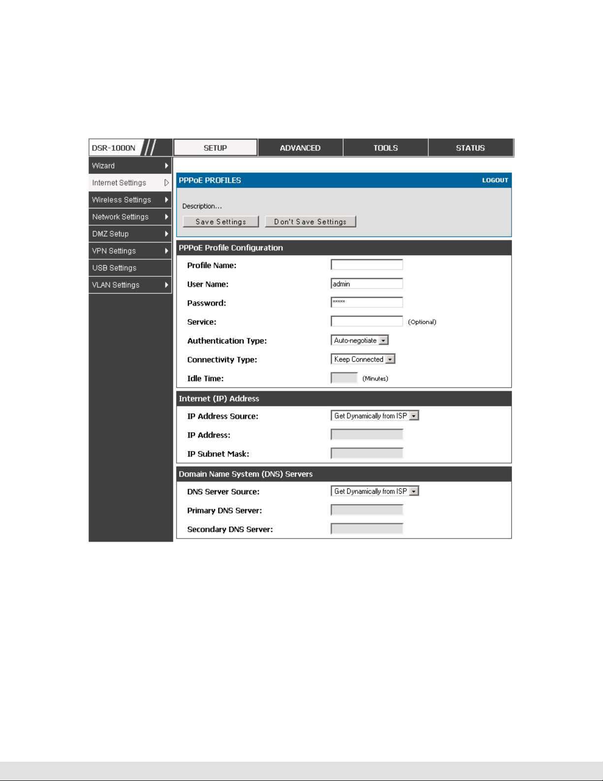
3.2.1
PPPoE Profiles
Setup > Internet Settings > PPPoE Profiles > WAN1 PPPoE Profiles
Some ISP’s allow for multiple concurrent PPPoE sessions (it is most
common in Japan). Each connection can have its own specific
authentication requirements and will provide unique IP, gateway, and DNS
address parameters to the associated WAN port.
The PPPoE Profiles page offers a convenient way to maintain multiple
PPPoE accounts, which can then be associated with one of the available
WAN interfaces. Once configured, a PPPoE profile name can be selected
on the WAN configuration page to reduce the configuration requirements for
that WAN port.
The PPPoE profile is referenced on the WAN Configuration page. The List of
PPPoE profiles for a particular WAN (see figure below) outlines the available
profile and their status and authentication type.
Figure 12: List of configured PPPoE profiles
To create a new PPPoE profile, select Add in the PPPoE Profile page. Each
profile is associated to one of the two WAN ports. Similar to the PPPoE
configuration options in the WAN configuration page, you need to define the
ISP logon credentials, authentication type, and connectivity settings for the
29
D-Link DSR Series Router
PPPoE session. This information will be provided by the ISP that offers
multiple PPPoE session support.
Figure 13: PPPoE profile configuration
3.2.2
WAN Configuration in an IPv6 Network
Setup > IPv6 > IPv6 WAN1 Config
For IPv6 WAN connections, this router can have a static IPv6 address or
receive connection information when configured as a DHCPv6 client. In the
case where the ISP assigns you a fixed address to access the internet, the
30

User Manual
static configuration settings must be completed. In addition to the IPv6
address assigned to your router, the IPv6 prefix length defined by the ISP is
needed. The default IPv6 Gateway address is the server at the ISP that this
router will connect to for accessing the internet. The primary and secondary
DNS servers on the ISP’s IPv6 network are used for resolving internet
addresses, and these are provided along with the static IP address and
prefix length from the ISP.
When the ISP allows you to obtain the WAN IP settings via DHCP, you need
to provide details for the DHCPv6 client configuration. The DHCPv6 client
on the gateway can be either stateless or stateful. If a stateful client is
selected the gateway will connect to the ISP’s DHCPv6 server for a leased
address. For stateless DHCP there need not be a DHCPv6 server available
at the ISP, rather ICMPv6 discover messages will originate from this
gateway and will be used for auto configuration. A third option to specify the
IP address and prefix length of a preferred DHCPv6 server is available as
well.
31

D-Link DSR Series Router
Figure 14: IPv6 WAN Setup page
3.2.3
Setup > Internet Settings > WAN Status
The status and summary of configured settings for both WAN1 and WAN2 are
available on the WAN Status page. You can view the following key
connection status information for each WAN port:
Checking WAN Status
Connection time
Connection type: dynamic IP or static IP
Connection state: This is whether the WAN is connected or disconnected to an
ISP. The Link State is whether the physical WAN connection in place; the Link
State can be UP (i.e. cable inserted) while the WAN Connection State is down.
32
IP address / subnet mask
Gateway IP address

User Manual
Figure 15: Connection Status information for both WAN ports
The WAN status page allows you to Enable or Disable static WAN links. For
WAN settings that are dynamically received from the ISP, you can Renew or
Release the link parameters if required.
33

3.3 Bandwidth Controls
Advanced > Advanced Network > Traffic Management > Bandwidth
Profiles
Bandwidth profiles allow you to regulate the traffic flow from the LAN to WAN
1 or WAN 2. This is useful to ensure that low priority LAN users (like guests
or HTTP service) does not monopolize the available WAN’s bandwidth for
cost-savings or bandwidth-priority-allocation purposes.
Bandwidth profiles configuration consists of enabling the bandwidth control
feature from the GUI and adding a profile which defines the control
parameters. The profile can then be associated with a traffic selector, so that
bandwidth profile can be applied to the traffic matching the selectors.
D-Link DSR Series Router
Selectors are elements like IP addresses or services that would trigger the
configured bandwidth regulation.
34
Figure 16: List of Configured Bandwidth Profiles
To create a new bandwidth profile, click Add in the List of Bandwidth
Profiles. The following configuration parameters are used to define a
bandwidth profile:

User Manual
Profile Name: This identifier is used to associate the configured profile to the
You can choose to limit the bandwidth either using priority or rate.
Choose the WAN interface that the profile should be associated with
traffic selector
• If using priority “Low”, “High”, “Medium” can be selected. If there is a low
priority profile associated with traffic selector A and a high priority profile
associated with traffic selector B, then the WAN bandwidth allocation
preference will be to traffic selector B packets.
• For finer control, the Rate profile type can be used. With this option the
minimum and maximum bandwidth allowed by this profile can be limited.
Figure 17: Bandwidth Profile Configuration page
Advanced > Advanced Network > Traffic Management > Traffic
Selectors
Once a profile has been created it can then be associated with a traffic flow
from the LAN to WAN. To create a traffic selector, click Add on the Traffic
35

D-Link DSR Series Router
Selectors page. Traffic selector configuration binds a bandwidth profile to a
type or source of LAN traffic with the following settings:
Available profiles: Assign one of the defined bandwidth profiles
Service: You can have the selected bandwidth regulation apply to a specific
service (i.e. FTP) from the LAN. If you do not see a service that you want, you
can configure a custom service through the Advanced > Firewall Settings
> Custom Services page. To have the profile apply to all services, select
ANY.
Traffic Selector Match Type: this defines the parameter to filter against when
applying the bandwidth profile. A specific machine on the LAN can be
identified via IP address or MAC address, or the profile can apply to a LAN
port or VLAN group. As well a wireless network can be selected by its BSSID
for bandwidth shaping.
36

User Manual
Figure 18: Traffic Selector Configuration
3.4 Features with Multiple WAN Links
This router supports multiple WAN links. This allows you to take advantage
of failover and load balancing features to ensure certain internet dependent
services are prioritized in the event of unstable WAN connectivity on one of
the ports.
Setup > Internet Settings > WAN Mode
To use Auto Failover or Load Balancing, WAN link failure detection must be
configured. This involves accessing DNS servers on the internet or ping to
an internet address (user defined). If required, you can configure the
number of retry attempts when the link seems to be disconnected or the
threshold of failures that determines if a WAN port is down.
3.4.1
Auto Failover
In this case one of your WAN ports is assigned as the primary internet link
for all internet traffic. The secondary WAN port is used for redundancy in
case the primary link goes down for any reason. Both WAN ports (primary
and secondary) must be configured to connect to the respective ISP’s before
37

D-Link DSR Series Router
enabling this feature. The secondary WAN port will remain unconnected
until a failure is detected on the primary link (either port can be assigned as
the primary). In the event of a failure on the primary port, all internet traffic
will be rolled over to the backup port. When configured in Auto Failover
mode, the link status of the primary WAN port is checked at regular intervals
as defined by the failure detection settings.
3.4.2
Load Balancing
This feature allows you to use multiple WAN links (and presumably multiple
ISP’s) simultaneously. After configuring more than one WAN port, the load
balancing option is available to carry traffic over more than one link.
Protocol bindings are used to segregate and assign services over one WAN
port in order to manage internet flow. The configured failure detection
method is used at regular intervals on all configured WAN ports when in
Load Balancing mode.
Load balancing is particularly useful when the connection speed of one WAN
port greatly differs from another. In this case you can define protocol
bindings to route low-latency services (such as VOIP) over the higher-speed
link and let low-volume background traffic (such as SMPT) go over the lower
speed link.
38

User Manual
Figure 19: Load Balancing is available when multiple WAN ports are
configured and Protocol Bindings have been defined
3.4.3
Protocol Bindings
Advanced > Routing > Protocol Bindings
Protocol bindings are required when the Load Balancing feature is in use.
Choosing from a list of configured services or any of the user-defined
services, the type of traffic can be assigned to go over only one of the
available WAN ports. For increased flexibility the source network or
machines can be specified as well as the destination network or machines.
For example the VOIP traffic for a set of LAN IP addresses can be assigned
39

D-Link DSR Series Router
to one WAN and any VIOP traffic from the remaining IP addresses can be
assigned to the other WAN link. Protocol bindings are only applicable when
load balancing mode is enabled and more than one WAN is configured.
Figure 20: Protocol binding setup to associate a service and/or LAN source
to a WAN and/or destination network
3.5 Routing Configuration
Routing between the LAN and WAN will impact the way this router handles
traffic that is received on any of its physical interfaces. The routing mode of
the gateway is core to the behavior of the traffic flow between the secure LAN
and the internet.
3.5.1
Routing Mode
Setup > Internet Settings > Routing Mode
This device supports classical routing, network address translation (NAT),
and transport mode routing.
40

User Manual
With classical routing, devices on the LAN can be directly accessed from
the internet by their public IP addresses (assuming appropriate firewall
settings). If your ISP has assigned an IP address for each of the
computers that you use, select Classic Routing.
NAT is a technique which allows several computers on a LAN to share an
Internet connection. The computers on the LAN use a "private" IP address
range while the WAN port on the router is configured with a single "public"
IP address. Along with connection sharing, NAT also hides internal IP
addresses from the computers on the Internet. NAT is required if your
ISP has assigned only one IP address to you. The computers that connect
through the router will need to be assigned IP addresses from a private
subnet.
Transparent mode routing between the LAN and WAN does not perform
NAT. Broadcast and multicast packets that arrive on the LAN interface
are switched to the WAN and vice versa, if they do not get filtered by
firewall or VPN policies. If the LAN and WAN are in the same broadcast
domain, select Transparent mode.
41
D-Link DSR Series Router
42
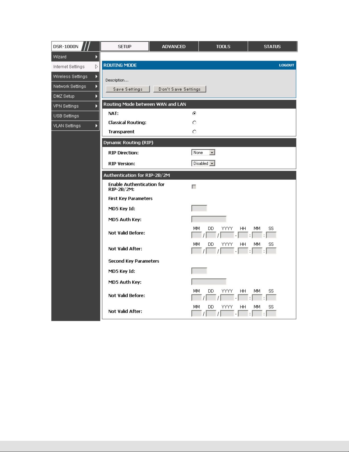
Figure 21: The Routing Mode page is used to configure the device’s routing
between WAN and LAN, as well as Dynamic routing (RIP)
3.5.2
Dynamic Routing (RIP)
Setup > Internet Settings > Routing Mode
Dynamic routing using the Routing Information Protocol (RIP) is an Interior
Gateway Protocol (IGP) that is common in LANs. With RIP this router can
exchange routing information with other supported routers in the LAN and

User Manual
allow for dynamic adjustment of routing tables in order to adapt to
modifications in the LAN without interrupting traffic flow.
The RIP direction will define how this router sends and receives RIP
packets. Choose between:
Both: The router both broadcasts its routing table and also processes RIP
Out Only: The router broadcasts its routing table periodically but does not
In Only: The router accepts RIP information from other routers, but does not
information received from other routers. This is the recommended setting in
order to fully utilize RIP capabilities.
accept RIP information from other routers.
broadcast its routing table.
None: The router neither broadcasts its route table nor does it accept any RIP
packets from other routers. This effectively disables RIP.
The RIP version is dependent on the RIP support of other routing devices in
the LAN.
Disabled: This is the setting when RIP is disabled.
RIP-1 is a class-based routing version that does not include subnet information.
This is the most commonly supported version.
RIP-2 includes all the functionality of RIPv1 plus it supports subnet information.
Though the data is sent in RIP-2 format for both RIP-2B and RIP-2M, the
mode in which packets are sent is different. RIP-2B broadcasts data in the
entire subnet while RIP-2M sends data to multicast addresses.
If RIP-2B or RIP-2M is the selected version, authentication between this
router and other routers (configured with the same RIP version) is required.
MD5 authentication is used in a first/second key exchange process. The
authentication key validity lifetimes are configurable to ensure that the
routing information exchange is with current and supported routers detected
on the LAN.
43

D-Link DSR Series Router
3.5.3
Static Routing
Advanced > Routing > Static Routing
Advanced > IPv6 > IPv6 Static Routing
Manually adding static routes to this device allows you to define the path
selection of traffic from one interface to another. There is no communication
between this router and other devices to account for changes in the path;
once configured the static route will be active and effective until the network
changes.
The List of Static Routes displays all routes that have been added manually
by an administrator and allows several operations on the static routes. The
List of IPv4 Static Routes and List of IPv6 Static Routes share the same
fields (with one exception):
Name: Name of the route, for identification and management.
Active: Determines whether the route is active or inactive. A route can be added
to the table and made inactive, if not needed. This allows routes to be used as
needed without deleting and re-adding the entry. An inactive route is not
broadcast if RIP is enabled.
Private: Determines whether the route can be shared with other routers when
RIP is enabled. If the route is made private, then the route will not be shared in
a RIP broadcast or multicast. This is only applicable for IPv4 static routes.
Destination: the route will lead to this destination host or IP address.
IP Subnet Mask: This is valid for IPv4 networks only, and identifies the subnet
that is affected by this static route
Interface: The physical network interface (WAN1, WAN2, DMZ or LAN), through
which this route is accessible.
Gateway: IP address of the gateway through which the destination host or
44
network can be reached.

User Manual
Metric: Determines the priority of the route. If multiple routes to the same
destination exist, the route with the lowest metric is chosen.
Figure 22: Static route configuration fields
3.6 Configurable Port - WAN Option
This router supports one of the physical ports to be configured as a secondary
WAN Ethernet port or a dedicated DMZ port. If the port is selected to be a
secondary WAN interface, all configuration pages relating to WAN2 are
enabled.
Setup > Internet Settings > WAN2 Setup
WAN2 configuration is identical to the WAN1 configuration with one significant
exception: configuration for the 3G USB modem is available only on WAN2.
45

D-Link DSR Series Router
Figure 23: WAN2 configuration for 3G internet (part 1)
Cellular 3G internet access is available on WAN2 via a USB modem. The
cellular ISP that provides the 3G data plan will provide the authentication
requirements to establish a connection. The dial Number and APN are
specific to the cellular carriers. Once the connection type settings are
configured and saved, navigate to the WAN status page (Setup > Internet
Settings > WAN Status) and Enable the WAN2 link to establish the 3G
connection.
46

User Manual
Figure 24: WAN2 configuration for 3G internet (part 2)
3.7 WAN Port Settings
Advanced > Advanced Network > WAN Port Setup
The physical port settings for each WAN link can be defined here. If your ISP
account defines the WAN port speed or is associated with a MAC address,
this information is required by the router to ensure a smooth connection with
the network.
47

D-Link DSR Series Router
The default MTU size supported by all ports is 1500. This is the largest
packet size that can pass through the interface without fragmentation. This
size can be increased, however large packets can introduce network lag and
bring down the interface speed. Note that a 1500 byte size packet is the
largest allowed by the Ethernet protocol at the network layer.
The port speed can be sensed by the router when Auto is selected. With this
option the optimal port settings are determined by the router and network.
The duplex (half or full) can be defined based on the port support, as well as
one of three port speeds: 10 Mbps, 100 Mbps and 1000 Mbps (i.e. 1 Gbps).
The default setting is 100 Mbps for all ports.
The default MAC address is defined during the manufacturing process for the
interfaces, and can uniquely identify this router. You can customize each
WAN port’s MAC address as needed, either by letting the WAN port assume
the current LAN host’s MAC address or by entering a MAC address manually.
48

User Manual
Figure 25: Physical WAN port settings
49

D-Link DSR Series Router
4. Wireless Access Point Setup
This router has an integrated 802.11n radio that allows you to create an access
point for wireless LAN clients. The security/encryption/authentication options are
grouped in a wireless Profile, and each configured profile will be available for
selection in the AP configuration menu. The profile defines various parameters for
the AP, including the security between the wireless client and the AP, and can be
shared between multiple APs instances on the same device when needed.
Up to four unique wireless networks can be created by configuring multiple “virtual”
APs. Each such virtual AP appears as an independent AP (unique SSID) to
supported clients in the environment, but is actually running on the same physical
radio integrated with this router.
You will need the following information to configure your wireless network:
Types of devices expected to access the wireless network and their supported
Wi-Fi™ modes
The router’s geographical region
The security settings to use for securing the wireless network.
Profiles may be thought of as a grouping of AP parameters that can then be
applied to not just one but multiple AP instances (SSIDs), thus avoiding
duplication if the same parameters are to be used on multiple AP instances
or SSIDs.
50
4.1 Wireless Settings Wizard
Setup > Wizard > Wireless Settings
The Wireless Network Setup Wizard is available for users new to networking.
By going through a few straightforward configuration pages you can enable a

User Manual
Wi-Fi™ network on your LAN and allow supported 802.11 clients to connect to
the configured Access Point.
Figure 26: Wireless Network Setup Wizards
4.1.1
Wireless Network Setup Wizard
This wizard provides a step-by-step guide to create and secure a new access
point on the router. The network name (SSID) is the AP identifier that will be
detected by supported clients. The Wizard uses a TKIP+AES cipher for WPA
/ WPA2 security; depending on support on the client side, devices associate
with this AP using either WPA or WPA2 security with the same pre-shared
key.
The wizard has the option to automatically generate a network key for the AP.
This key is the pre-shared key for WPA or WPA2 type security. Supported
clients that have been given this PSK can associate with this AP. The default
(auto-assigned) PSK is “passphrase”.
51

D-Link DSR Series Router
The last step in the Wizard is to click the Connect button, which confirms the
settings and enables this AP to broadcast its availability in the LAN.
4.1.2
Add Wireless Device with WPS
With WPS enabled on your router, the selected access point allows supported
WPS clients to join the network very easily. When the Auto option for
connecting a wireless device is chose, you will be presented with two common
WPS setup options:
Personal Identification Number (PIN): The wireless device that supports
WPS may have an alphanumeric PIN, and if entered in this field the AP will
establish a link to the client. Click Connect to complete setup and connect to
the client.
Push Button Configuration (PBC): for wireless devices that support PBC,
press and hold down on this button and within 2 minutes, click the PBC
connect button. The AP will detect the wireless device and establish a link to
the client.
You need to enable at least one AP with WPA/WPA2 security and also
enable WPS in the Advanced > Wireless Settings > WPS page to use the
WPS wizard.
4.1.3
Manual Wireless Network Setup
This button on the Wizard page will link to the Setup > Wireless Settings >
Access Points page. The manual options allow you to create new APs or
modify the parameters of APs created by the Wizard.
4.2 Wireless Profiles
Setup > Wireless Settings > Profiles
The profile allows you to assign the security type, encryption and
authentication to use when connecting the AP to a wireless client. The default
mode is “open”, i.e. no security. This mode is insecure as it allows any
52

User Manual
compatible wireless clients to connect to an AP configured with this security
profile.
To create a new profile, use a unique profile name to identify the combination
of settings. Configure a unique SSID that will be the identifier used by the
clients to communicate to the AP using this profile. By choosing to broadcast
the SSID, compatible wireless clients within range of the AP can detect this
profile’s availability.
The AP offers all advanced 802.11 security modes, including WEP, WPA,
WPA2 and WPA+WPA2 options. The security of the Access point is
configured by the Wireless Security Type section:
Open: select this option to create a public “open” network to allow
unauthenticated devices to access this wireless gateway.
WEP (Wired Equivalent Privacy): this option requires a static (pre-shared) key
to be shared between the AP and wireless client. Note that WEP does not
support 802.11n data rates; is it appropriate for legacy 802.11 connections.
WPA (Wi-Fi Protected Access): For stronger wireless security than WEP,
choose this option. The encryption for WPA will use TKIP and also CCMP if
required. The authentication can be a pre-shared key (PSK), Enterprise mode
with RADIUS server, or both. Note that WPA does not support 802.11n data
rates; is it appropriate for legacy 802.11 connections.
WPA2: this security type uses CCMP encryption (and the option to add TKIP
encryption) on either PSK (pre-shared key) or Enterprise (RADIUS Server)
authentication.
WPA + WPA2: this uses both encryption algorithms, TKIP and CCMP. WPA
clients will use TKIP and WPA2 clients will use CCMP encryption algorithms.
“WPA+WPA2” is a security option that allows devices to connect to an AP
using the strongest security that it supports. This mode allows legacy
devices that only support WPA2 keys (such as an older wireless printer) to
connect to a secure AP where all the other wireless clients are using WPA2.
53

D-Link DSR Series Router
Figure 27: List of Available Profiles shows the variety of options available
to secure the wireless link
4.2.1
WEP Security
If WEP is the chosen security option, you must set a unique static key to be
shared with clients that wish to access this secured wireless network. This
static key can be generated from an easy-to-remember passphrase and the
selected encryption length.
Authentication: select between Open System, or Shared Key schemes
Encryption: select the encryption key size -- 64 bit WEP or 128 bit WEP. The
larger size keys provide stronger encryption, thus making the key more difficult
to crack
WEP Passphrase: enter a alphanumeric phrase and click Generate Key to
generate 4 unique WEP keys with length determined by the encryption key
size. Next choose one of the keys to be used for authentication. The selected
key must be shared with wireless clients to connect to this device.
54

User Manual
Figure 28: Profile configuration to set network security
4.2.2
WPA or WPA2 with PSK
A pre-shared key (PSK) is a known passphrase configured on the AP and
client both and is used to authenticate the wireless client. An acceptable
passphrase is between 8 to 63 characters in length.
55

D-Link DSR Series Router
4.2.3
Setup > Wireless Settings > RADIUS Settings
RADIUS Authentication
Enterprise Mode uses a RADIUS Server for WPA and/or WPA2 security. A
RADIUS server must be configured and accessible by the router to
authenticate wireless client connections to an AP enabled with a profile that
uses RADIUS authentication.
The Authentication IP Address is required to identify the server. A secondary
RADIUS server provides redundancy in the event that the primary server
cannot be reached by the router when needed.
Authentication Port: the port for the RADIUS server connection
Secret: enter the shared secret that allows this router to log into the specified
RADIUS server(s). This key must match the shared secret on the RADIUS
Server.
The Timeout and Retries fields are used to either move to a secondary server
if the primary cannot be reached, or to give up the RADIUS authentication
attempt if communication with the server is not possible.
56

User Manual
Figure 29: RADIUS server (External Authentication) configuration
4.3 Creating and Using Access Points
Setup > Wireless Settings > Access Points
Once a profile (a group of security settings) is created, it can be assigned to
an AP on the router. The AP SSID can be configured to broadcast its
availability to the 802.11 environment can be used to establish a WLAN
network.
The AP configuration page allows you to create a new AP and link to it one of
the available profiles. This router supports multiple AP’s referred to as virtual
access points (VAPs). Each virtual AP that has a unique SSIDs appears as an
independent access point to clients. This valuable feature allows the router’s
radio to be configured in a way to optimize security and throughput for a
group of clients as required by the user. To create a VAP, click the “add”
button on the Setup > Wireless Settings > Access Points page. After
setting the AP name, the profile dropdown menu is used to select one of the
configured profiles.
57

D-Link DSR Series Router
The AP Name is a unique identifier used to manage the AP from the GUI,
and is not the SSID that is detected by clients when the AP has broadcast
enabled.
Figure 30: Virtual AP configuration
A valuable power saving feature is the start and stop time control for this AP.
You can conserve on the radio power by disabling the AP when it is not in
use. For example on evenings and weekends if you know there are no
wireless clients, the start and stop time will enable/disable the access point
automatically.
Once the AP settings are configured, you must enable the AP on the radio on
the Setup > Wireless Settings > Access Points page. The status field
changes to “Enabled” if the AP is available to accept wireless clients. If the
AP is configured to broadcast its SSID (a profile parameter), a green check
mark indicating it is broadcasting will be shown in the List of Available Access
points.
58

User Manual
Figure 31: List of configured access points (Virtual APs) shows one enabled
access point on the radio, broadcasting its SSID
The clients connected to a particular AP can be viewed by using the Status
Button on the List of Available Access Points. Traffic statistics are shown for
that individual AP, as compared to the summary stats for each AP on the
Statistics table. Connected clients are sorted by the MAC address and
indicate the security parameters used by the wireless link, as well as the time
connected to this particular AP. Clicking the Details button next to the
connected client will give the detailed send and receive traffic statistics for the
wireless link between this AP and the client.
4.3.1
Optimize throughput: if 802.11b, 802.11 g, and 802.11n clients are expected
Primary benefits of Virtual APs:
to access the LAN via this router, creating 3 VAPs will allow you to manage or
shape traffic for each group of clients. A unique SSID can be created for the
network of 802.11b clients and another SSID can be assigned for the 802.11n
clients. Each can have different security parameters – remember, the SSID
and security of the link is determined by the profile. In this way legacy clients
can access the network without bringing down the overall throughput of more
capable 802.11n clients.
59

D-Link DSR Series Router
Optimize security: you may wish to support select legacy clients that only
offer WEP security while using WPA2 security for the majority of clients for
the radio. By creating two VAPs configured with different SSIDs and different
security parameters, both types of clients can connect to the LAN. Since
WPA2 is more secure, you may want to broadcast this SSID and not
broadcast the SSID for the VAP with WEP since it is meant to be used for a
few legacy devices in this scenario.
4.4 Tuning Radio Specific Settings
Setup > Wireless Settings > Radio Settings
The Radio Settings page lets you configure the channels and power levels
available for the AP’s enabled on the device. The router has a dual band
802.11n radio, meaning either 2.4 GHz or 5 GHz frequency of operation can
be selected (not concurrently though). Based on the selected operating
frequency, the mode selection will let you define whether legacy connections
or only 802.11n connections (or both) are accepted on configured APs.
60

User Manual
Figure 32: Radio card configuration options
The ratified 802.11n support on this radio requires selecting the appropriate
broadcast (NA or NG etc.) mode, and then defining the channel spacing and
control side band for 802.11n traffic. The default settings are appropriate for
most networks. For example, changing the channel spacing to 40 MHz can
improve bandwidth at the expense of supporting earlier 802.11n clients.
The available transmission channels are governed by regulatory constraints
based on the region setting of the router. The maximum transmission power
is similarly governed by regulatory limits; you have the option to decrease
from the default maximum to reduce the signal strength of traffic out of the
radio.
4.5 Advanced Wireless Settings
Advanced > Wireless Settings > Advanced Wireless
Sophisticated wireless administrators can modify the 802.11 communication
parameters in this page. Generally, the default settings are appropriate for
61

D-Link DSR Series Router
most networks. Please refer to the GUI integrated help text for further details
on the use of each configuration parameter.
Figure 33: Advanced Wireless communication settings
4.6 Wi-Fi Protected Setup (WPS)
Advanced > Wireless Settings > WPS
WPS is a simplified method to add supporting wireless clients to the network.
WPS is only applicable for APs that employ WPA or WPA2 security. To use
WPS, select the eligible VAPs from the dropdown list of APs that have been
configured with this security and enable WPS status for this AP.
The WPS Current Status section outlines the security, authentication, and
encryption settings of the selected AP. These are consistent with the AP’s
profile. There are two setup options available for WPS:
62

User Manual
Personal Identification Number (PIN): The wireless device that supports
WPS may have an alphanumeric PIN, if so add the PIN in this field. The
router will connect within 60 seconds of clicking the “Configure via PIN” button
immediately below the PIN field. There is no LED indication that a client has
connected.
Push Button Configuration (PBC): for wireless devices that support PBC,
press and hold down on this button and within 2 minutes click the PBC
connect button. The AP will detect the wireless device and establish a link to
the client.
More than one AP can use WPS, but only one AP can be used to establish
WPS links to client at any given time.
63

D-Link DSR Series Router
Figure 34: WPS configuration for an AP with WPA/WPA2 profile
64

5. Securing the Private Network
You can secure your network by creating and applying rules that your router uses
to selectively block and allow inbound and outbound Internet traffic. You then
specify how and to whom the rules apply. To do so, you must define the following:
Services or traffic types (examples: web browsing, VoIP, other standard
services and also custom services that you define)
Direction for the traffic by specifying the source and destination of traffic; this is
done by specifying the “From Zone” (LAN/WAN/DMZ) and “To Zone”
(LAN/WAN/DMZ)
Schedules as to when the router should apply rules
Any Keywords (in a domain name or on a URL of a web page) that the router
should allow or block
Rules for allowing or blocking inbound and outbound Internet traffic for
specified services on specified schedules
MAC addresses of devices that should not access the internet
Port triggers that signal the router to allow or block access to specified services
as defined by port number
Reports and alerts that you want the router to send to you
You can, for example, establish restricted-access policies based on time-of-day,
web addresses, and web address keywords. You can block Internet access by
applications and services on the LAN, such as chat rooms or games. You can
block just certain groups of PCs on your network from being accessed by the WAN
or public DMZ network.
5.1 Firewall Rules
Advanced > Firewall Settings > Firewall Rules
Inbound (WAN to LAN/DMZ) rules restrict access to traffic entering your network,
selectively allowing only specific outside users to access specific local resources.
65

D-Link DSR Series Router
By default all access from the insecure WAN side are blocked from accessing the
secure LAN, except in response to requests from the LAN or DMZ. To allow
outside devices to access services on the secure LAN, you must create an inbound
firewall rule for each service.
If you want to allow incoming traffic, you must make the router’s WAN port IP
address known to the public. This is called “exposing your host.” How you make
your address known depends on how the WAN ports are configured; for this router
you may use the IP address if a static address is assigned to the WAN port, or if
your WAN address is dynamic a DDNS (Dynamic DNS) name can be used.
Outbound (LAN/DMZ to WAN) rules restrict access to traffic leaving your network,
selectively allowing only specific local users to access specific outside resources.
The default outbound rule is to allow access from the secure zone (LAN) to either
the public DMZ or insecure WAN. You can change this default behavior in the
Firewall Settings > Default Outbound Policy page. When the default outbound
policy is allow always, you can to block hosts on the LAN from accessing internet
services by creating an outbound firewall rule for each service.
66

User Manual
Figure 35: List of Available Firewall Rules
5.2 Defining Rule Schedules
Tools > Schedules
Firewall rules can be enabled or disabled automatically if they are associated
with a configured schedule. The schedule configuration page allows you to
define days of the week and the time of day for a new schedule, and then this
schedule can be selected in the firewall rule configuration page.
All schedules will follow the time in the routers configured time zone. Refer
to the section on choosing your Time Zone and configuring NTP servers for
more information.
67

D-Link DSR Series Router
Figure 36: List of Available Schedules to bind to a firewall rule
5.3 Configuring Firewall Rules
Advanced > Firewall Settings > Firewall Rules
All configured firewall rules on the router are displayed in the Firewall Rules
list. This list also indicates whether the rule is enabled (active) or not, and
gives a summary of the From/To zone as well as the services or users that
the rule affects.
To create a new firewall rules, follow the steps below:
1.
View the existing rules in the List of Available Firewall Rules table.
2.
To edit or add an outbound or inbound services rule, do the following:
To edit a rule, click the checkbox next to the rule and click Edit to reach that
rule’s configuration page.
To add a new rule, click Add to be taken to a new rule’s configuration page.
Once created, the new rule is automatically added to the original table.
68
3.
Chose the From Zone to be the source of originating traffic: either the secure
LAN, public DMZ, or insecure WAN. For an inbound rule WAN should be
selected as the From Zone.

User Manual
4.
Choose the To Zone to be the destination of traffic covered by this rule. If the
From Zone is the WAN, the To Zone can be the public DMZ or secure LAN.
Similarly if the From Zone is the LAN, then the To Zone can be the public DMZ or
insecure WAN.
5.
Parameters that define the firewall rule include the following:
• Service: ANY means all traffic is affected by this rule. For a specific
service the drop down list has common services, or you can select a
custom defined service.
• Action & Schedule: Select one of the 4 actions that this rule defines:
BLOCK always, ALLOW always, BLOCK by schedule otherwise ALLOW,
or ALLOW by schedule otherwise BLOCK. A schedule must be
preconfigured in order for it to be available in the dropdown list to assign
to this rule.
Source & Destination users: For each relevant category, select the users to
which the rule applies:
• Any (all users)
• Single Address (enter an IP address)
• Address Range (enter the appropriate IP address range)
Log: traffic that is filtered by this rule can be logged; this requires configuring
the router’s logging feature separately.
QoS Priority: Outbound rules (where To Zone = insecure WAN only) can have
the traffic marked with a QoS priority tag. Select a priority level:
• Normal-Service: ToS=0 (lowest QoS)
• Minimize-Cost: ToS=1
• Maximize-Reliability: ToS=2
• Maximize-Throughput: ToS=4
69

D-Link DSR Series Router
Minimize-Delay: ToS=8 (highest QoS)
6.
Inbound rules can use Destination NAT (DNAT) for managing traffic from the
WAN. Destination NAT is available when the To Zone = DMZ or secure LAN.
With an inbound allow rule you can enter the internal server address that is
hosting the selected service.
You can enable port forwarding for an incoming service specific rule (From
Zone = WAN) by selecting the appropriate checkbox. This will allow the
selected service traffic from the internet to reach the appropriate LAN port via
a port forwarding rule.
Translate Port Number: With port forwarding, the incoming traffic to be
forwarded to the port number entered here.
External IP address: The rule can be bound to a specific WAN interface by
selecting either the primary WAN or configurable port WAN as the source IP
address for incoming traffic.
This router supports multi-NAT and so the External IP address does not
necessarily have to be the WAN address. On a single WAN interface,
multiple public IP addresses are supported. If your ISP assigns you more
than one public IP address, one of these can be used as your primary IP
address on the WAN port, and the others can be assigned to servers on the
LAN or DMZ. In this way the LAN/DMZ server can be accessed from the
internet by its aliased public IP address.
7.
Outbound rules can use Source NAT (SNAT) in order to statically map (bind) all
70
LAN/DMZ traffic matching the rule parameters to a specific WAN interface or
external IP address (usually provided by your ISP).

User Manual
Once the new or modified rule parameters are saved, it appears in the master list of
firewall rules. To enable or disable a rule, click the checkbox next to the rule in the
list of firewall rules and choose Enable or Disable.
The router applies firewall rules in the order listed. As a general rule, you
should move the strictest rules (those with the most specific services or
addresses) to the top of the list. To reorder rules, click the checkbox next to
a rule and click up or down.
71

D-Link DSR Series Router
72
Figure 37: The firewall rule configuration page allows you to define the
To/From zone, service, action, schedules, and specify source/destination IP
addresses as needed.

User Manual
5.3.1
Firewall Rule Configuration Examples
Example 1: Allow inbound HTTP traffic to the DMZ
Situation: You host a public web server on your local DMZ network. You
want to allow inbound HTTP requests from any outside IP address to the IP
address of your web server at any time of day.
Solution: Create an inbound rule as follows.
Parameter Value
From Zone Insecure (WAN1/WAN2)
To Zone Public (DMZ)
Service HTTP
Action ALLOW always
Send to Local Server
192.168.5.2 (web server IP address)
(DNAT IP)
Destination Users Any
Log Never
Example 2: Allow videoconferencing from range of outside IP addresses
Situation: You want to allow incoming videoconferencing to be initiated from
a restricted range of outside IP addresses (132.177.88.2 - 132.177.88.254),
from a branch office.
Solution: Create an inbound rule as follows. In the example, CUSeeMe (the
video conference service used) connections are allowed only from a
specified range of external IP addresses.
73

Parameter Value
From Zone Insecure (WAN1/WAN2)
To Zone Secure (LAN)
Service CU-SEEME:UDP
Action ALLOW always
D-Link DSR Series Router
Send to Local Server
(DNAT IP)
Destination Users Address Range
From 132.177.88.2
To 134.177.88.254
Enable Port Forwarding Yes (enabled)
Example 3: Multi-NAT configuration
Situation: You want to configure multi-NAT to support multiple public IP
addresses on one WAN port interface.
Solution: Create an inbound rule that configures the firewall to host an
additional public IP address. Associate this address with a web server on the
192.168.10.11
74
DMZ. If you arrange with your ISP to have more than one public IP address
for your use, you can use the additional public IP addresses to map to
servers on your LAN. One of these public IP addresses is used as the
primary IP address of the router. This address is used to provide Internet
access to your LAN PCs through NAT. The other addresses are available to
map to your DMZ servers.
The following addressing scheme is used to illustrate this procedure:
Router
WAN IP address: 10.1.0.118

User Manual
LAN IP address: 192.168.10.1; subnet 255.255.255.0
Web server host in the DMZ, IP address: 192.168.12.222
Access to Web server: (simulated) public IP address 10.1.0.52
Parameter Value
From Zone Insecure (WAN1/WAN2)
To Zone Public (DMZ)
Service HTTP
Action ALLOW always
Send to Local Server (DNAT IP) 192.168.12.222 ( web server local IP address)
Destination Users Single Address
From 10.1.0.52
WAN Users Any
Log Never
Example 4: Block traffic by schedule if generated from specific range of
machines
Use Case: Block all HTTP traffic on the weekends if the request originates
from a specific group of machines in the LAN having a known range of IP
addresses, and anyone coming in through the Network from the WAN (i.e. all
remote users).
Configuration:
1.
Setup a schedule:
To setup a schedule that affects traffic on weekends only, navigate to Security:
Schedule, and name the schedule “Weekend”
75

D-Link DSR Series Router
Define “weekend” to mean 12 am Saturday morning to 12 am Monday morning
– all day Saturday & Sunday
In the Scheduled days box, check that you want the schedule to be active for
“specific days”. Select “Saturday” and “Sunday”
In the scheduled time of day, select “all day” – this will apply the schedule
between 12 am to 11:59 pm of the selected day.
Click apply – now schedule “Weekend” isolates all day Saturday and Sunday
from the rest of the week.
76

User Manual
Figure 38: Schedule configuration for the above example.
2.
Since we are trying to block HTTP requests, it is a service with To Zone: Insecure
(WAN1/WAN2) that is to be blocked according to schedule “Weekend”.
77

D-Link DSR Series Router
3.
Select the Action to “Block by Schedule, otherwise allow”. This will take a
predefined schedule and make sure the rule is a blocking rule during the defined
dates/times. All other times outside the schedule will not be affected by this
firewall blocking rule
4.
As we defined our schedule in schedule “Weekend”, this is available in the
dropdown menu
5.
We want to block the IP range assigned to the marketing group. Let’s say they
have IP 192.168.10.20 to 192.168.10.30. On the Source Users dropdown, select
Address Range and add this IP range as the From and To IP addresses.
6.
We want to block all HTTP traffic to any services going to the insecure zone. The
Destination Users dropdown should be “any”.
7.
We don’t need to change default QoS priority or Logging (unless desired) –
clicking apply will add this firewall rule to the list of firewall rules.
8.
The last step is to enable this firewall rule. Select the rule, and click “enable”
below the list to make sure the firewall rule is active
5.4 Security on Custom Services
Advanced > Firewall Settings > Custom Services
Custom services can be defined to add to the list of services available during
firewall rule configuration. While common services have known
TCP/UDP/ICMP ports for traffic, many custom or uncommon applications
exist in the LAN or WAN. In the custom service configuration menu you can
define a range of ports and identify the traffic type (TCP/UDP/ICMP) for this
service. Once defined, the new service will appear in the services list of the
firewall rules configuration menu.
78
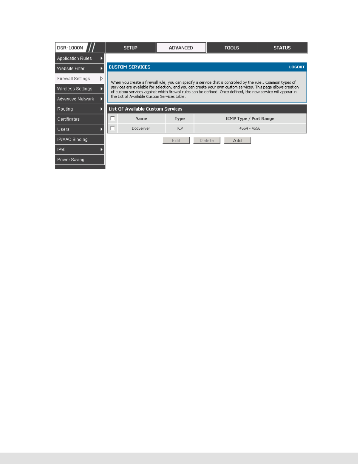
User Manual
Figure 39: Schedule configuration for the above example.
5.5 ALG support
Advanced > Firewall Settings > ALGs
Application Level Gateways (ALGs) are security component that enhance the
firewall and NAT support of this router to seamlessly support application layer
protocols. In some cases enabling the ALG will allow the firewall to use
dynamic ephemeral TCP/ UDP ports to communicate with the known ports a
particular client application (such as H.323 or RTSP) requires, without which
the admin would have to open large number of ports to accomplish the same
support. Because the ALG understands the protocol used by the specific
application that it supports, it is a very secure and efficient way of introducing
support for client applications through the router’s firewall.
79

D-Link DSR Series Router
Figure 40: Available ALG support on the router.
5.6 VPN Passthrough for Firewall
Advanced > Firewall Settings > VPN Passthrough
This router’s firewall settings can be configured to allow encrypted VPN traffic
for IPsec, PPTP, and L2TP VPN tunnel connections between the LAN and
internet. A specific firewall rule or service is not appropriate to introduce this
passthrough support; instead the appropriate check boxes in the VPN
Passthrough page must be enabled.
80

User Manual
Figure 41: Passthrough options for VPN tunnels
5.7 Application Rules
Advanced > Application Rules > Application Rules
Application rules are also referred to as port triggering. This feature allows
devices on the LAN or DMZ to request one or more ports to be forwarded to
them. Port triggering waits for an outbound request form the LAN/DMZ on
one of the defined outgoing ports, and then opens an incoming port for that
specified type of traffic. This can be thought of as a form of dynamic port
forwarding while an application is transmitting data over the opened outgoing
or incoming port(s).
Port triggering application rules are more flexible than static port forwarding
that is an available option when configuring firewall rules. This is because a
port triggering rule does not have to reference a specific LAN IP or IP range.
As well ports are not left open when not in use, thereby providing a level of
security that port forwarding does not offer.
Port triggering is not appropriate for servers on the LAN, since there is a
dependency on the LAN device making an outgoing connection before
incoming ports are opened.
81

D-Link DSR Series Router
Some applications require that when external devices connect to them, they
receive data on a specific port or range of ports in order to function properly.
The router must send all incoming data for that application only on the
required port or range of ports. The router has a list of common applications
and games with corresponding outbound and inbound ports to open. You can
also specify a port triggering rule by defining the type of traffic (TCP or UDP)
and the range of incoming and outgoing ports to open when enabled.
Figure 42: List of Available Application Rules showing 4 unique rules
The application rule status page will list any active rules, i.e. incoming ports
that are being triggered based on outbound requests from a defined outgoing
port.
5.8 Web Content Filtering
The gateway offers some standard web filtering options to allow the admin to
easily create internet access policies between the secure LAN and insecure
WAN. Instead of creating policies based on the type of traffic (as is the case
when using firewall rules), web based content itself can be used to determine
if traffic is allowed or dropped.
82

User Manual
Content Filtering
Advanced > Website Filter > Content Filtering
Content filtering must be enabled to configure and use the subsequent
features (list of Trusted Domains, filtering on Blocked Keywords, etc.). Proxy
servers, which can be used to circumvent certain firewall rules and thus a
potential security gap, can be blocked for all LAN devices. Java applets can
be prevented from being downloaded from internet sites, and similarly the
gateway can prevent ActiveX controls from being downloaded via Internet
Explorer. For added security cookies, which typically contain session
information, can be blocked as well for all devices on the private network.
Figure 43: Content Filtering used to block access to proxy servers and
prevent ActiveX controls from being downloaded
Approved URLs
Advanced > Website Filter > Approved URLs
The Approved URLs is an acceptance list for all URL domain names.
Domains added to this list are allowed in any form. For example, if the
83

D-Link DSR Series Router
domain “yahoo” is added to this list then all of the following URL’s are
permitted access from the LAN: www.yahoo.com, yahoo.co.uk, etc.
Figure 44: Two trusted domains added to the Approved URLs List
Blocked Keywords
Advanced > Website Filter > Blocked URLs
Keyword blocking allows you to block all website URL’s or site content that
contains the keywords in the configured list. This is lower priority than the
Approved URL List; i.e. if the blocked keyword is present in a site allowed by
a Trusted Domain in the Approved URL List, then access to that site will be
allowed.
84

User Manual
Figure 45: Two keywords added to the block list
5.9 IP/MAC Binding
Advanced > IP/MAC Binding
Another available security measure is to only allow outbound traffic (from the
LAN to WAN) when the LAN node has an IP address matching the MAC
address bound to it. This is IP/MAC Binding, and by enforcing the gateway to
validate the source traffic’s IP address with the unique MAC Address of the
configured LAN node, the administrator can ensure traffic from that IP
address is not spoofed. In the event of a violation (i.e. the traffic’s source IP
address doesn’t match up with the expected MAC address having the same IP
address) the packets will be dropped and can be logged for diagnosis.
85

D-Link DSR Series Router
Figure 46: The above example of IP/MAC Binding binds a LAN host’s MAC
Address to an IP address. If there is an IP/MAC Binding violation, the
violating packet will be dropped and logs will be captured
5.10 Intrusion Prevention (IPS)
Advanced > Advanced Network > IPS
The gateway’s Intrusion Prevention System (IPS) prevents malicious attacks
from the internet from accessing the private network. Static attack signatures
loaded to the device allow common attacks to be detected and prevented.
The checks can be enabled between the WAN and DMZ or LAN, and a
running counter will allow the administrator to see how many malicious
intrusion attempts from the WAN have been detected and prevented.
86

User Manual
Figure 47: Intrusion Prevention features on the router
5.10.1
Protecting from Internet Attacks
Advanced > Advanced Network > Attack Checks
Attacks can be malicious security breaches or unintentional network issues
that render the router unusable. Attack checks allow you to manage WAN
security threats such as continual ping requests and discovery via ARP scans.
TCP and UDP flood attack checks can be enabled to manage extreme usage
of WAN resources.
Additionally certain Denial-of-Service (DoS) attacks can be blocked. These
attacks, if uninhibited, can use up processing power and bandwidth and
prevent regular network services from running normally. ICMP packet
flooding, SYN traffic flooding, and Echo storm thresholds can be configured to
temporarily suspect traffic from the offending source.
87

D-Link DSR Series Router
Figure 48: Protecting the router and LAN from internet attacks
88

User Manual
6. IPsec VPN
A VPN provides a secure communication channel (“tunnel”) between two gateway
routers or a remote PC client. The following types of tunnels can be created:
Gateway-to-gateway VPN: to connect two or more routers to secure traffic
between remote sites.
Remote Client (client-to-gateway VPN tunnel): A remote client initiates a VPN
tunnel as the IP address of the remote PC client is not known in advance. The
gateway in this case acts as a responder.
Remote client behind a NAT router: The client has a dynamic IP address and is
behind a NAT Router. The remote PC client at the NAT router initiates a VPN
tunnel as the IP address of the remote NAT router is not known in advance. The
gateway WAN port acts as responder.
6.1 VPN Wizard
Setup > Wizard > VPN Wizard
You can use the VPN wizard to quickly create both IKE and VPN policies.
Once the IKE or VPN policy is created, you can modify it as required.
89

D-Link DSR Series Router
Figure 49: VPN Wizard launch screen
To easily establish a VPN tunnel using VPN Wizard, follow the steps below:
1.
Step 1: Select the VPN tunnel type to create
The tunnel can either be a gateway to gateway connection (site-to-site) or a
tunnel to a host on the internet (remote access).
Set the Connection Name and pre-shared key: the connection name is used for
management, and the pre-shared key will be required on the VPN client or
gateway to establish the tunnel
Determine the local gateway for this tunnel; if there is more than 1 WAN
configured the tunnel can be configured for either of the gateways.
2.
Step 2: Configure Remote and Local WAN address for the tunnel endpoints
Remote Gateway Type: identify the remote endpoint of the tunnel by FQDN or
90
static IP address
Remote WAN IP address / FQDN: This field is enabled only if the peer you are
trying to connect to is a Gateway. For VPN Clients, this IP address or Internet
Name is determined when a connection request is received from a client.

User Manual
Local Gateway Type: identify this router’s endpoint of the tunnel by FQDN or
Local WAN IP address / FQDN: This field can be left blank if you are not using
3.
Step 3: Configure the Secure Connection Remote Accessibility fields to identify
the remote network:
Remote LAN IP address: address of the LAN behind the peer gateway
Remote LAN Subnet Mask: the subnet mask of the LAN behind the peer
static IP address
a different FQDN or IP address than the one specified in the WAN port’s
configuration.
Note: The IP address range used on the remote LAN must be different from
the IP address range used on the local LAN.
4.
Step4: review the settings and click Connect to establish the tunnel.
The Wizard will create a corresponding IKE policy with the following default
values for a VPN Client or Gateway policy (these can be accessed from a link
on the Wizard page):
Parameter Default value from Wizard
Exchange Mode Aggressive (Client policy ) or Main (Gateway policy)
ID Type FQDN
Local WAN ID wan_local.com (only applies to Client policies)
Remote WAN ID wan_remote.com (only applies to Client policies)
Encryption Algorithm 3DES
Authentication Algorithm SHA-1
Authentication Method Pre-shared Key
91
D-Link DSR Series Router
Key-Group DH-Group 2(1024 bit)
Life Time 24 hours
As well, the Wizard will create a matching VPN policy to the IKE policy with
the following default values:
Parameter Default value from Wizard
Encryption Algorithm 3DES
Authentication Algorithm SHA-1
Life Time 8 hours
PFS Key Group DH-Group 2(1024 bit)
NETBIOS Enabled (only applies to Gateway policies)
The VPN Wizard is the recommended method to set up corresponding IKE
and VPN policies for establishing a VPN tunnel. Once the Wizard creates
the matching IKE and VPN policies, one can modify the required fields
through the edit link. Advanced users can create an IKE policy from the
Add link but must be sure to use compatible encryption, authentication, and
key-group parameters for the VPN policy. Refer to the online help for
details.
6.2 Configuring IKE Policies
Setup > VPN Settings > IPsec > IKE Policies
92
The Internet Key Exchange (IKE) protocol dynamically exchanges keys
between two IPsec hosts. You can create IKE policies to define the security
parameters such as authentication of the peer, encryption algorithms, etc. to
be used in this process.

User Manual
IKE policies can be created by clicking “Add” on the VPN > IKE Policies web
page.
93

D-Link DSR Series Router
94
Figure 50: IKE policy created by the VPN Wizard then modified manually

User Manual
6.2.1
Configuring an IKE Policy using XAUTH
You can also configure extended authentication (XAUTH). Rather than
configure a unique VPN policy for each user, you can configure the VPN
gateway router to authenticate users from a stored list of user accounts or
with an external authentication server such as a RADIUS server. With a user
database, user accounts created in the router are used to authenticate
users.
With a configured RADIUS server, the router connects to a RADIUS server
and passes to it the credentials that it receives from the VPN client. You can
secure the connection between the router and the RADIUS server with the
authentication protocol supported by the server (PAP or CHAP). For RADIUS
– PAP, the router first checks in the user database to see if the user
credentials are available; if they are not, the router connects to the RADIUS
server.
6.3 Configuring VPN Policies
Setup > VPN Settings > IPsec > VPN Policies
The VPN policy is one half of the IKE/VPN policy pair required to establish a
VPN tunnel. The IP addresses of the machine or machines on the two VPN
endpoints are configured here, along with the policy parameters required to
secure the tunnel.
95

D-Link DSR Series Router
96
Figure 51: VPN policy created by the VPN Wizard then modified manually

User Manual
Figure 52: VPN policy created by the VPN Wizard then modified manually
(continued)
6.4 Configuring VPN clients
Remote VPN clients must be configured with the same VPN policy parameters
used in the VPN tunnel that the client wishes to use: encryption,
authentication, life time, and PFS key-group. Upon establishing these
authentication parameters, the VPN Client user database must also be
populated with an account to give a user access to the tunnel.
VPN client software is required to establish a VPN tunnel between the
router and remote endpoint. Open source software (such as OpenVPN or
Openswan) as well as Microsoft IPSec VPN software can be configured with
the required IKE policy parameters to establish an IPSec VPN tunnel. Refer
to the client software guide for detailed instructions on setup as well as the
router’s online help.
The user database contains the list of VPN user accounts that are authorized
to use a given VPN tunnel. Alternatively VPN tunnel users can be
authenticated using a configured Radius database. Refer to the online help to
determine how to populate the user database and/or configure RADIUS
authentication.
97

D-Link DSR Series Router
6.5 PPTP / L2TP Tunnels
This router supports VPN tunnels from either PPTP or L2TP ISP servers. The
router acts as a broker device to allow the ISP's server to create a TCP
control connection between the LAN VPN client and the VPN server.
6.5.1
PPTP Tunnel Support
Setup > VPN Settings > PPTP > PPTP Server
A PPTP VPN can be established through this router. If the WAN mode has
configured a PPTP ISP, then LAN hosts on this router can connect directly to
the PPTP server. The PPTP server will indicate the range of IP addresses in
your LAN to assign to LAN side VPN clients to allow the PPTP clients to
establish a direct tunnel to the WAN side PPTP server.
98
Figure 53: PPTP tunnel configuration – PPTP Server
6.5.2
L2TP Tunnel Support
Setup > VPN Settings > L2TP > L2TP Server
A L2TP VPN can be established through this router If the WAN mode has
configured a L2TP ISP, then LAN hosts on this router can connect directly to
the L2TP server. The L2TP server will indicate the range of IP addresses in

User Manual
your LAN to assign to LAN side VPN clients to allow the L2TP clients to
establish a direct tunnel to the WAN side L2TP server.
Figure 54: L2TP tunnel configuration – L2TP Server
99

 Loading...