

Page 1

GLV-540 IP Phone
User Manual
Rev 1.0.3
1
Page 2

GLV-540 User Manual
Table of Contents
TABLE OF CONTENTS .............................................................................................................................. 2
TABLE OF FIGURES .................................................................................................................................. 4
1 OVERVIEW .......................................................................................................................................... 6
1.1 A
1.2 D
2 UNPACKING AND INSTALLATION ............................................................................................... 9
2.1 C
2.2 I
2.3 I
3 PRODUCT OVERVIEW .................................................................................................................... 11
4 GETTING STARTED ......................................................................................................................... 12
4.1 G
4.2 C
4.3 C
4.4 I
4.5 A
5 FEATURES .......................................................................................................................................... 31
5.1 P
5.2 C
CRONYMS
EFINITIONS
ONNECTING YOUR
NSTALLATION
NFRASTRUCTURE REQUIREMENTS
ETTING FAMILIAR WITH THE
ONFIGURING THROUGH WEB BROWSER
ONFIGURING THROUGH
NITIATING AN OUTGOING CALL
........................................................................................................................................ 7
...................................................................................................................................... 8
GLV IP P
HONE
................................................................................................ 9
.................................................................................................................................... 9
................................................................................................ 10
LCD
AND
KEYPAD ........................................................................ 12
...................................................................................... 13
LCD ........................................................................................................ 20
...................................................................................................... 25
4.4.1 Off hook dialing ..................................................................................................................... 25
4.4.2 On Hook dialing .................................................................................................................... 25
4.4.3 Dial using Phone book........................................................................................................... 26
4.4.4 Dial using Speed Dial ............................................................................................................ 26
4.4.5 Redial ..................................................................................................................................... 27
4.4.6 IP Address dialing ................................................................................................................. 27
4.4.7 E.164 Calls ............................................................................................................................ 28
4.4.8 Call using a specific SIP Account .......................................................................................... 28
NSWERING AN INCOMING CALL
.................................................................................................... 29
4.5.1 Single Incoming Call ............................................................................................................. 29
4.5.2 Multiple Incoming Calls ........................................................................................................ 29
HONE FEATURES
.......................................................................................................................... 31
5.1.1 Multi User .............................................................................................................................. 31
5.1.2 User Mode ............................................................................................................................. 32
5.1.3 User Status ............................................................................................................................. 32
5.1.4 Default User .......................................................................................................................... 32
5.1.5 User Privilege ........................................................................................................................ 33
5.1.6 Multi Line .............................................................................................................................. 33
5.1.7 Auto Configuration ................................................................................................................ 33
5.1.8 Configuration Backup and Restore........................................................................................ 33
5.1.9 Factory Reset ......................................................................................................................... 35
5.1.10 Software Upgrade .................................................................................................................. 35
5.1.11 Help ....................................................................................................................................... 36
5.1.12 Access Control ....................................................................................................................... 36
5.1.13 User Lock ............................................................................................................................... 36
5.1.14 Key Mode ............................................................................................................................... 37
5.1.15 Country Code ......................................................................................................................... 37
5.1.16 Downloadable Tones ............................................................................................................. 37
5.1.17 IP Modes ................................................................................................................................ 38
5.1.18 NTP ........................................................................................................................................ 39
5.1.19 SIP Server Discovery ............................................................................................................. 39
5.1.20 NAT Traversal ....................................................................................................................... 39
5.1.21 Remote Monitoring using SIP Trace ..................................................................................... 40
5.1.22 Remote Monitoring using syslog............................................................................................ 40
5.1.23 Remote Monitoring using E-mail ........................................................................................... 41
5.1.24 Feature Key Sequence ........................................................................................................... 42
ALL FEATURES
.............................................................................................................................. 43
5.2.1 Do Not Disturb (DnD) ........................................................................................................... 43
2
Page 3

GLV-540 User Manual
5.2.2 Call Forward ......................................................................................................................... 43
5.2.3 Selective Call Accept, Reject, Forward ................................................................................. 43
5.2.4 Auto Answer ........................................................................................................................... 43
5.2.5 Call Waiting ........................................................................................................................... 44
5.2.6 Anonymous Call/ Caller ID Block ......................................................................................... 44
5.2.7 Anonymous Call Rejection ..................................................................................................... 44
5.2.8 Peer-to-Peer calls .................................................................................................................. 44
5.2.9 Hotline ................................................................................................................................... 45
5.2.10 Warmline ............................................................................................................................... 45
5.2.11 Voicemail Message Waiting Indication ................................................................................. 45
5.2.12 Dial plan ................................................................................................................................ 46
5.2.13 Call Hold ............................................................................................................................... 46
5.2.14 Call Transfer ......................................................................................................................... 46
5.2.15 3-Way Conference ................................................................................................................. 48
5.2.16 Camp-on ................................................................................................................................ 48
5.2.17 Call Park & Retrieve ............................................................................................................. 49
5.2.18 Call Pickup ............................................................................................................................ 49
5.2.19 Call Return ............................................................................................................................ 50
5.2.20 DTMF Mode .......................................................................................................................... 50
6 CONFIGURATION GUIDE .............................................................................................................. 51
6.1 C
6.2 C
ONFIGURATION THROUGH
ONFIGURATION THROUGH WEB BROWSER
LCD .................................................................................................... 51
.................................................................................. 53
7 APPENDIX .......................................................................................................................................... 97
7.1 A
7.2 A
7.3 A
PPENDIX A: FREQUENTLY ASKED QUESTIONS
PPENDIX B: TROUBLESHOOTING
PPENDIX C: ENTERING ALPHANUMERIC AND SPECIAL CHARACTERS
................................................................................................ 105
(FAQ)................................................................. 97
....................................... 107
7.3.1 Key Mode ............................................................................................................................. 107
7.3.2 Entering Digits .................................................................................................................... 107
7.3.3 Entering Small Letters & Capital Letters ............................................................................ 107
7.3.4 Entering Special Characters ................................................................................................ 107
7.4 A
7.5 A
7.6 A
7.7 A
7.8 V
PPENDIX D: CALL FEATURE PRECEDENCE
PPENDIX E: PRODUCT SPECIFICATIONS
PPENDIX F: USE CASES
PPENDIX G: GLOSSARY OF VOIP TERMS
ARIANTS FOR
GLV-540 .............................................................................................................. 116
............................................................................................................. 111
.................................................................................... 109
................................................................................ 108
.................................................................................. 112
7.9 WARRANTY POLICY ................................................................................................................ 117
3
Page 4

Table of Figures
F
IGURE 1:
F
IGURE 2:
F
IGURE 3: SECURITY ALERT WINDOW
F
IGURE 4: LOGIN THROUGH WEB BROWSER
F
IGURE 5:
F
IGURE 6: NETWORK CONFIGURATION
F
IGURE 7:
F
IGURE 8: USER CONFIGURATION
F
IGURE 9: USER CONFIGURATION (NEW USER
F
IGURE
F
IGURE
F
IGURE
F
IGURE
F
IGURE
F
IGURE
F
IGURE
F
IGURE
F
IGURE
F
IGURE
F
IGURE
F
IGURE
F
IGURE
F
IGURE
F
IGURE
F
IGURE
F
IGURE
F
IGURE
F
IGURE
F
IGURE
F
IGURE
F
IGURE
F
IGURE
F
IGURE
F
IGURE
F
IGURE
F
IGURE
F
IGURE
F
IGURE
F
IGURE
F
IGURE
F
IGURE
GLV-540 ......................................................................................................................................... 6
GLV-540 LCD
AND KEYPAD INTERFACE
.......................................................................................................... 13
GLV-540 H
OME PAGE
................................................................................................................. 14
.......................................................................................................... 15
SIP C
ONFIGURATION
..................................................................................................................... 16
.................................................................................................................. 17
10: A
PPLY CHANGES
11: M
ENU LOGIN SCREEN
12: I
NFORMATION SCREEN
13: IP S
ETTINGS
14: IP M
15: IP A
16: N
17: D
18: VOIP S
19: VOIP S
20: VOIP S
21: VOIP S
22: VOIP S
23: VOIP S
24: VOIP S
25: VOIP S
26: E
27: I
28: O
29: ON H
30: D
31: S
32: R
33: A
34: A
35: I
36: M
37: C
38: B
39: A
40: F
41: F
ODE
DDRESS
ET MASK
EFAULT GATEWAY IP ADDRESS
ETTINGS
ETTINGS
ETTINGS
ETTINGS
ETTINGS
ETTINGS
ETTINGS
ETTINGS (OUTBOUND
XIT SCREEN
DLE SCREEN
FF HOOK DIALING
OOK DIALING
IAL USING PHONE BOOK
PEED DIAL
EDIAL
........................................................................................................................................ 27
NSWERING AN INCOMING CALL (SINGLE
NSWERING AN INCOMING CALL (MULTIPLE
NDIVIDUAL USER PROFILES AND
ULTIPLE USER PROFILES SHARING A
ALL TRANSFER
LIND CALL TRANSFER
TTENDED CALL TRANSFER
LOW CHART FOR CONFIGURATION THROUGH
LOW CHART FOR CONFIGURATION THROUGH
......................................................................................................................... 19
.................................................................................................................. 20
................................................................................................................ 20
................................................................................................................................ 20
...................................................................................................................................... 21
................................................................................................................................. 21
................................................................................................................................... 21
........................................................................................................................... 22
(SIP U
SER NAME
(SIP P
HONE NUMBER
(SIP A
UTH NAME
(SIP A
UTH PASSWORD
(SIP S
ERVER ADDRESS
(SIP S
ERVER PORT
............................................................................................................................... 24
............................................................................................................................... 24
..................................................................................................................... 25
....................................................................................................................... 25
........................................................................................................... 26
................................................................................................................................. 26
.......................................................................................................................... 46
............................................................................................................... 47
........................................................................................................ 47
GLV-540 User Manual
.................................................................................... 12
.................................................................................................. 14
) ............................................................................................. 18
................................................................................................ 21
) .............................................................................................. 22
) ....................................................................................... 22
) ............................................................................................. 22
) ..................................................................................... 23
) ..................................................................................... 23
) ........................................................................................... 23
SIP P
ROXY
) ................................................................................... 24
) .................................................................................. 29
) .............................................................................. 30
SIP A
CCOUNTS
SIP A
........................................................................ 31
CCOUNT
.................................................................. 31
LCD (A
LCD (U
DMIN PRIVILEGE
SER PRIVILEGE
) ................................... 51
) ...................................... 52
4
Page 5

Table of Tables
T
ABLE 1 : DEFINITION OF
T
ABLE 2: KEY FEATURES AT A GLANCE
T
ABLE 3: KEY DESCRIPTION AND
T
ABLE 4: FEATURE ACCESS CODES
T
ABLE 5: DEVICE CONFIGURATION
T
ABLE 6: AUDIO CONFIGURATION
T
ABLE 7: NETWORK CONFIGURATION
T
ABLE 8:
T
ABLE 9: SIP CONFIGURATION: ADVANCED SETTINGS
T
ABLE
T
ABLE
T
ABLE
T
ABLE
T
ABLE
T
ABLE
T
ABLE
T
ABLE
T
ABLE
T
ABLE
T
ABLE
T
ABLE
T
ABLE
T
ABLE
T
ABLE
T
ABLE
T
ABLE
T
ABLE
T
ABLE
T
ABLE
T
ABLE
T
ABLE
T
ABLE
T
ABLE
T
ABLE
T
ABLE
T
ABLE
T
ABLE
SIP C
ONFIGURATION
10: U
SER CONFIGURATION: - USERS
11: U
SER CONFIGURATION: - FEATURES
12: U
SER CONFIGURATION: - ADVANCED FEATURES
13: P
HONE BOOK: - OTHER FEATURES
14: S
PEED DIAL
15: D
IAL PLAN
16: D
EVICE MANAGEMENT: SOFTWARE
17: D
EVICE MANAGEMENT: CONFIGURATION
18: D
EVICE MANAGEMENT: DEBUG SETUP
19: D
EVICE MANAGEMENT: ACCESS CONTROL
20: D
EVICE MANAGEMENT: USER LOCK
21: D
EVICE MONITOR: UPGRADE HISTORY
22: D
EVICE MONITOR: CONFIG HISTORY
23: D
EVICE MONITOR: CALL HISTORY
24: D
EVICE MONITOR: ALARMS
25: D
EVICE MONITOR: DEBUG MESSAGES
26: D
EVICE MONITOR:
27: D
EVICE MANAGEMENT: APPLY CHANGES
28: R
ESTART SYSTEM
29: F
ACTORY RESET
30: H
ELP
............................................................................................................................................ 96
31: L
OGOUT
32: S
YSTEM STATUS CODES
33: C
ALL STATUS CODES
34: H
ARDWARE SPECIFICATION
35: T
ECHNICAL SPECIFICATIONS
36: V
ARIANTS OF
37: V
ARIANTS FOR DC ADAPTER FOR
GLV-540
CONNECTORS
......................................................................................................... 11
LED
COLORS
............................................................................................. 13
................................................................................................................ 42
................................................................................................................ 53
................................................................................................................. 57
............................................................................................................ 59
...................................................................................................................... 64
................................................................................................... 69
............................................................................................. 70
................................................................................................ 76
.................................................................................................................................. 78
.................................................................................................................................... 80
............................................................................................. 82
............................................................................................ 90
............................................................................................ 91
............................................................................................... 92
........................................................................................................ 93
SIP T
RACE
..................................................................................................... 95
........................................................................................................................ 95
.......................................................................................................................... 96
....................................................................................................................................... 96
.............................................................................................................. 105
: ................................................................................................................. 106
........................................................................................................ 109
...................................................................................................... 109
GLV-540
UNITS
.................................................................................................... 116
GLV-540 ............................................................................... 116
GLV-540 User Manual
......................................................................................... 9
.................................................................................. 68
.......................................................................... 73
.................................................................................... 84
........................................................................................ 88
.................................................................................. 90
........................................................................................ 91
......................................................................................... 94
.................................................................................... 95
5
Page 6

GLV-540 User Manual
1 Overview
The GLV-540 is a cost effective, easy to use and easy to configure VoIP phone.
The GLV uses state-of-the-art proven technology to provide quality voice
communication and supports popular voice codec’s. GLV is based on SIP industry
standard and inter-operates with most IP telephony systems, thus enabling you
to leverage the benefits of VoIP technology. GLV is designed for home users with
broadband internet access and office users in a LAN environment behind
NAT/Firewall. It provides all essential functions and features for office and home
users through a user friendly and intuitive LCD interface.
GLV-540 IP phone is simple to use and will work in any existing SIP
infrastructure with little a configuration. It gives the complete flexibility to
configure the Phone parameters through LCD and web browser.
This User Manual describes the features and functionalities of GLV-540 IP Phone.
This manual will help you to learn how to operate and manage your GLV-540 IP
Phone and make best use of its many features.
6
Figure 1: GLV-540
Page 7

GLV Features
Multi user and Multi Line Support
Large Graphical LCD Display with soft keys
Support for speaker phone and Head phone
Power Over Ethernet
Dual Ethernet port with auto-switching
Wide band codec for high quality
Call Hold with Music on Hold.
Call transfer –Attended & Blind
Conference
Call Waiting Indication
Call Forwarding-Unconditional, No Answer, Busy,
Selective call Acceptance, rejection and forward
Call Park & Retrieve
Call Pickup
Camp-on
DND, Auto Answer
Hot Line / Warm Line
Message Waiting Indication
E.164
Phone Book and Speed dial with 100 entries each
Call Logs with Received Call, Missed Call and Dialed Call
Phone Lock with password protection
Downloadable Call Progress Tone
Caller ID and Call duration display
Fail safe remote software upgrade
NAT Traversal with STUN and IP Sharing
GLV-540 User Manual
1.1 Acronyms
AJB Adaptive Jitter Buffer
CNG Comfort Noise Generation
DTMF Dual Tone Multi Frequency
DHCP Dynamic Host Configuration Protocol
DND Do Not Disturb
DNS Domain Name Service
HTTP Hyper Text Transport Protocol
IP Internet Protocol
ITSP IP Telephony Service Provider
LCD Liquid Crystal Display
LED Light Emitting Diode
NAT Network Address Translator
NTP Network Time Protocol
PoE Power over Ethernet
PoE-SW Power over Ethernet-Switch
PoE-PC Power over Ethernet-PC
PPP Point-to-Point Protocol
PPPOE Point-to-Point Protocol over Ethernet
QIG Quick Installation Guide
RTP Real Time Protocol
RTCP Real Time Control Protocol
SDP Session Description Protocol
SIP Session Initiation Protocol
TFTP Trivial File Transfer Protocol
VAD Voice Activate Detection
VLAN Virtual Local Area Network
VOIP Voice over Internet Protocol, same as Internet Telephony
7
Page 8

GLV-540 User Manual
1.2 Definitions
Speaker Mode: You can dial a phone number in hands free mode and have
conversation with the other party.
Handset Mode: You can lift the handset any time to listen. If the speaker is on
while lifting, it is turned Off automatically.
Headset Mode: You can press the headset button any time to listen. If the
speaker is on while lifting, it is turned Off automatically.
Locked State: In this state you can only receive calls.
8
Page 9

GLV-540 User Manual
2 Unpacking and Installation
Open the shipping carton and carefully remove all items. In addition to this
User’s Guide, make sure you have received all of the following items:
• GLV-540 IP phone
• One Ethernet cable (RJ-45)
• Handset
• Handset cord
• Power adapter (DC 5V-3A) ***
• Quick Install Guide
• Foot stand
• User Manual and QIG CD
If any item appears to be missing or damaged, please contact your local reseller.
*** Refer to Variants of GLV-540 unit and adapters.
2.1 Connecting your GLV IP Phone
Table 1 : Definition of GLV-540 connectors
PoE-SW 10/100 Mbps RJ-45 port for uplink to Ethernet.
PoE-PC 10/100 Mbps RJ-45 port for connecting to PC. (switch
functionality)
Power Jack 5V-3A DC power port.
Headset
Speaker
Headset Mike 3.5 mm stereo phone jack for mike.
Headset
Speaker & Mike
Handset Handset RJ-12 jack
Reset To reset the board
3.5 mm stereo phone jack for speaker.
Headset RJ-12 jack
2.2 Installation
1. Connect the Foot Stand to the back side of the GLV-540.
2. Connect the handset to GLV-540 with handset cord.
3. Plug one end of Ethernet cable into the PoE-SW port (RJ-45) on the rear panel
of GLV-540 and the other end into a working LAN/WAN networking connection
through an Ethernet switch or hub. Led glowing Red in color indicates that
Phone is booting and after the phone comes up it indicates the status of PoESW port; when this Led is Red, Ethernet is not connected and glowing Green
indicates, Ethernet is connected.
4. Optionally connect the Ethernet port labeled PoE-PC to the Ethernet port of
your PC/laptop for accessing the LAN network in switched mode.
5. Plug the power adaptor provided into an AC outlet and insert the power cord
into the connector marked “DC 5V-3A” on the rear panel of the GLV-540.
6. On power up the LED’s will flicker for sometime and LCD will display
‘Initializing’ message till the phone is ready for use. Lift the handset and listen
for the tone, a tone on handset speaker indicates the GLV-540 has been
9
Page 10

GLV-540 User Manual
installed and powered ON properly. If you are not able to hear any tone,
check that the power adaptor is plugged into a live electrical outlet and that
the power cord is inserted securely into the connector.
7. Now GLV-540 is ready for basic configuration as described in the section
Getting Started.
Note:
To use the wallmount feature of the phone case, reverse the Wallmount lock so
as to hold the Handset when the phone is hanged at the wall.
2.3 Infrastructure Requirements
This section describes the infrastructure requirements for proper functioning of
D-Link IP phone (GLV-540).
1. The D-Link GLV phone can work in 10/100 Mbps LAN network. Connecting the
GLV Ethernet port to a switch is recommended, this will help to provide good
quality voice communication.
2. GLV-540 phone needs a set of IP parameters for proper functioning like IP
address, Net mask, gateway address, and DNS server addresses. These
parameters can be configured statically through LCD or Web browser or even
dynamically through DHCP.
3. GLV-540 phones need a valid SIP Account to make or receive VoIP calls. IP
phone will register the assigned phone number with the SIP server on power
up. However, D-Link GLV-540 phone can initiate calls by directly dialing
destination sip URI address even without registering to SIP server.
4. If your LAN network has any firewall or NAT, then either network should
support SIP-ALG or you have to enable STUN / IP-SHARING at the GLV-540 to
make and receive calls from outside your network.
5. A TFTP / HTTP server is required to support remote software upgrade. Please
refer to software upgrade section for the upgrade procedure.
6. A PC which supports any of the following browsers for configuring the system
through web.
o On Windows:
I.E version 6.0 or more
Mozilla Firefox version 1.0 or more
Mozilla version 1.7.13 or more
Netscape version 8.0.3.3 or more
o On Linux:
Mozilla version 0.0.9
Galeon version 1.2.7
10
Page 11

GLV-540 User Manual
3 Product Overview
GLV is an easy to use IP Phone with advanced features and is ideal for use at home
and office. GLV supports multiple user profiles allowing the IP phone to be
personalized for individual users.
For example: In a home environment IP Phone can be shared by members of a
family, where each family member can personalize the phone features through a
separate user profile.
The GLV multiple SIP account feature facilitates receiving calls destined for home and
office in a single IP Phone. One can use more than one ITSP accounts (maximum 5)
to receive and initiate calls; this allows the flexibility to use a particular ITSP account
for call to a specific numbers or location.
For example: Consider call charges of ITSP A are lower for calls to the Middle-East in
comparison to call charges of ITSP B, whereas ITSP B has lower call charge for calls
to Asia. GLV provides the flexibility to choose an ITSP account for each call to
leverage benefits for lower call charges offered by a particular ITSP account.
GLV supports advanced features such as 3-Way-Conferencing that facilitate seamless
conference hosting at GLV with two more parties participating in the conference. A
high quality speaker phone allows loud and clear communication that is essential for
any conference user.
GLV provides group listen feature that allows listening to an ongoing conversation,
this can be useful in a call centre environment where a supervisor can monitor an
executive in call with a customer. Here the executive can take either Headset or
Handset, while the supervisor can listen to the conversation on the speaker phone.
Table 2: Key Features at a glance
Open
Standards
Compatible
Network
Interfaces
Excellent
Audio Quality
Feature Rich Caller ID, call waiting, call hold, call transfer, call forward, do not
Advanced
Features
SIP 2.0, TCP/IP/UDP, RTP/RTCP, HTTP/HTTPS, ARP/RARP, ICMP,
IEEE 802.1 Q VLAN, DNS (A record, SRV, NAPTR), E.164, DHCP,
PPPoE, TFTP, SMTP, and NTP.
Dual (2) 10/100 auto-sensing Ethernet ports (switched), with PoE
support
Digital Signal Processing (DSP), Silence suppression, VAD, CNG,
AEC, AGC, wide band codec.
disturb, selective call accept/reject/forward, camp-on, hot line,
call park, call retrieve, call pickup, message waiting indication, call
statistics, group listen (headset/handset), mute.
Multi line support, Multiple users, Multiple SIP accounts, 3-way
Call Conference
11
Page 12
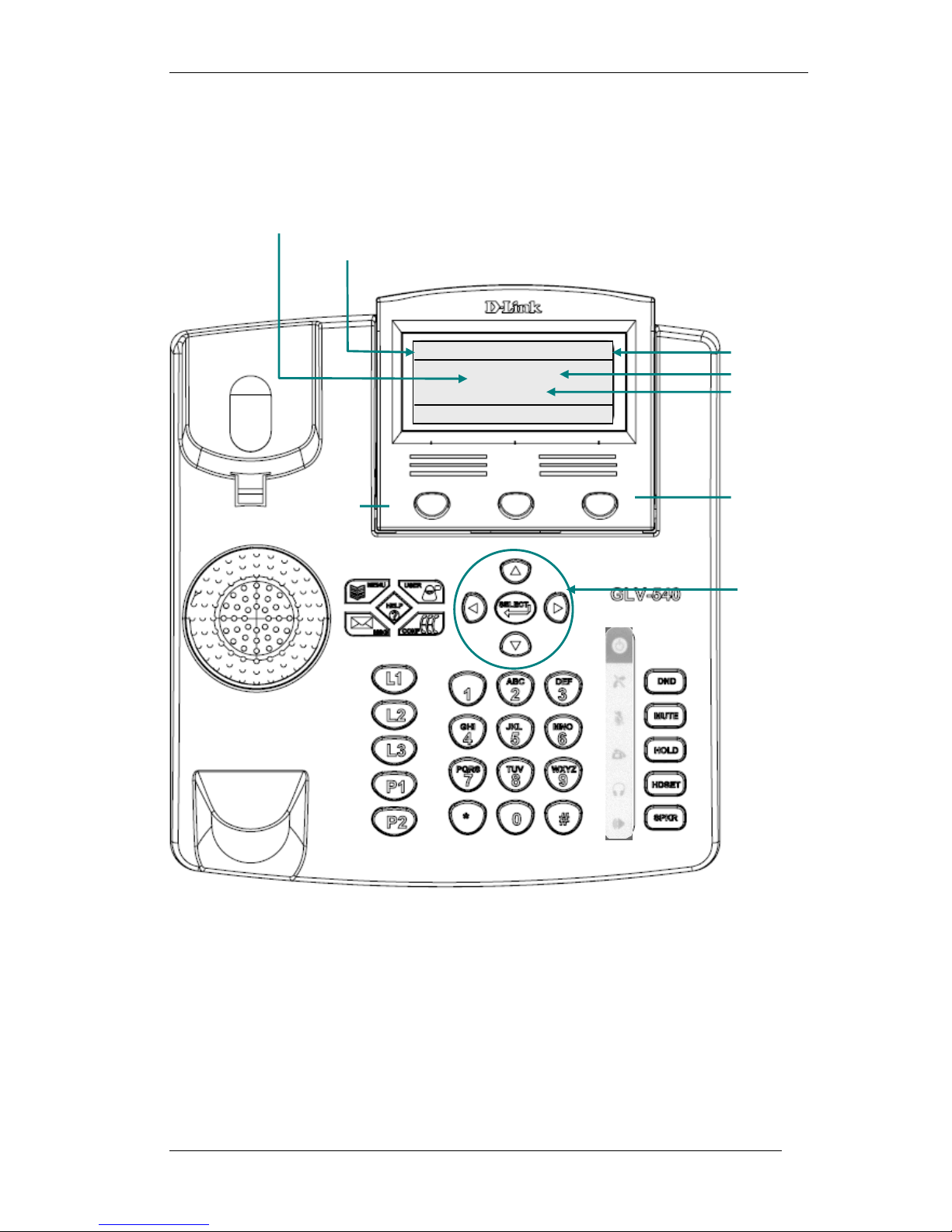
03 Jan 07
GLV 07:52:38
Time
Phone Number
Date
Display Name
4 Getting Started
4.1 Getting Familiar with the LCD and KEYPAD
IPPhone 101
NewCall PBook Redial
Soft Key
GLV-540 User Manual
Configurable Welcome
Message
Soft Key
Navigation Keys
12
Figure 2: GLV-540 LCD and Keypad Interface
Page 13
GLV-540 User Manual
Table 3: Key Description and LED colors
Key name Functionality LED
MENU To enter into configuration state. Blue
USER To change user status Blue
MSG Indication of waiting voice mail and to access Voice
Mail.
CONF To initiate 3 way Conference Blue
HELP To enter the Help Menu Blue
L1 To select Line 1. Blue
L2 To select Line 2. Blue
L3 To select Line 3. Blue
P1 The function key Blue
P2 The Programmable key (currently set to Speed Dial) Blue
Navigation Keys Left, Right, Top & Bottom arrow used for navigation of
list and volume control
SELECT To select an entry from any list None
DND To enable / disable Do Not Disturb feature Red
MUTE To Mute / Un Mute the phone in a call Red
HOLD To keep the remote party on Hold Red
HDSET To turn ON / OFF the Headset. Blue
SPKR To turn ON or OFF the speakerphone. Blue
Numeric Keypad Standard telephone key pad. None
Blue
None
4.2 Configuring through Web Browser
The GLV can be configured through the Web Interface using a web browser
such as Microsoft IE (see section 2.3 for the supported web browsers). When
GLV is powered up for the first time, the Phone-IP-address is set to 10.0.0.1.
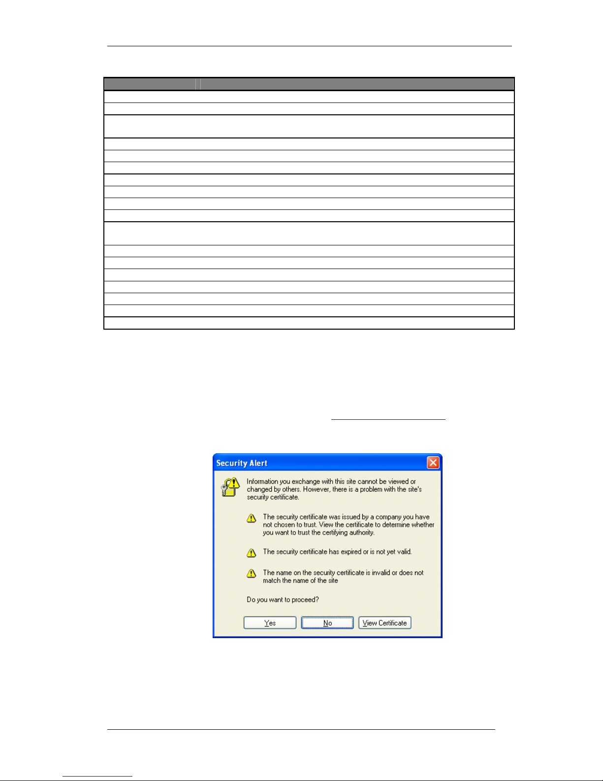
Open a web browser and access the URL http://Phone-IP-address to access the
embedded web server on the IP phone. The browser will ask for confirmation
weather to accept the security certificate.
Figure 3: Security Alert window
13
Page 14
GLV-540 User Manual
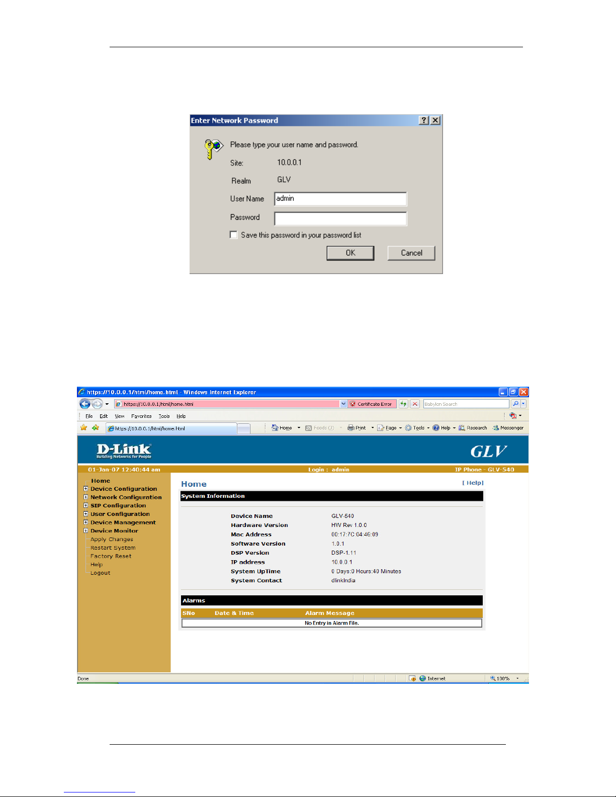
Click “Yes” button, the browser will ask for the authentication parameters. The
administrator login has the user name as “admin” and password as “123”.
The home page of GLV-540 will now be displayed as shown in Figure 5: GLV-540
Home page.
Figure 4: Login through Web Browser
Note:
To access the IP Phone GUI through a web browser, the PC and the IP Phone
need to be in the same network/subnet.
Upon logging in the IP Phone Home Page is displayed:
14
Figure 5: GLV-540 Home page
Page 15
GLV-540 User Manual
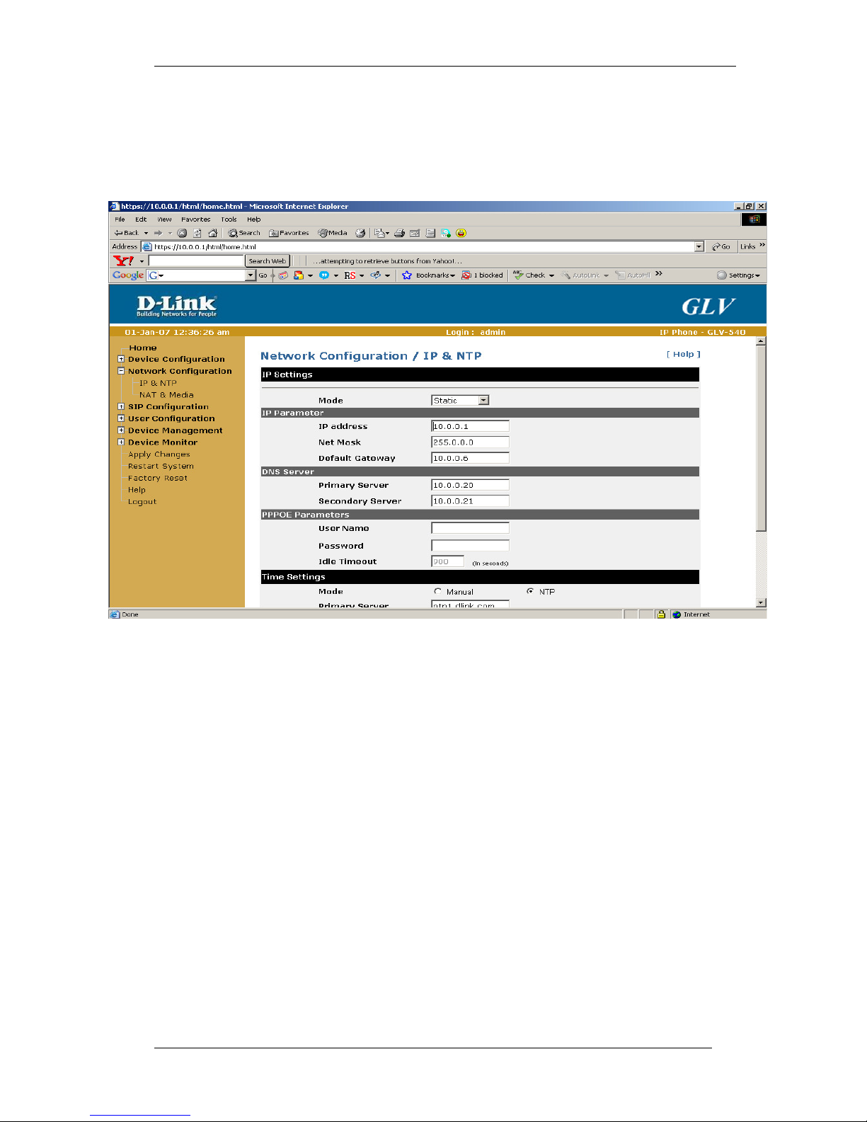
To change the Phone IP address, Click on the “Network ConfigurationIP
& NTP” link to get the IP Settings page.
Set the IP mode to Static/ DHCP/ PPPoE and accordingly modify the
related IP parameters. Now click on the “Save” button to save the
configuration.
Figure 6: Network Configuration
15
Page 16
GLV-540 User Manual
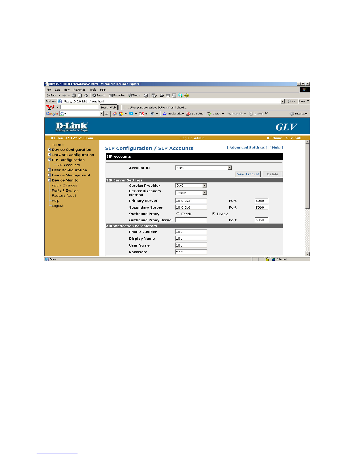
To add a SIP Account, Click on the “SIP ConfigurationSIP Accounts” link.
Add a new SIP account and configure the SIP account parameters: account id, primary / secondary server IP & port, phone number, display
name, authentication user name and authentication password. Save the
changes by clicking on the “Save” button.
Figure 7: SIP Configuration
16
Page 17
GLV-540 User Manual
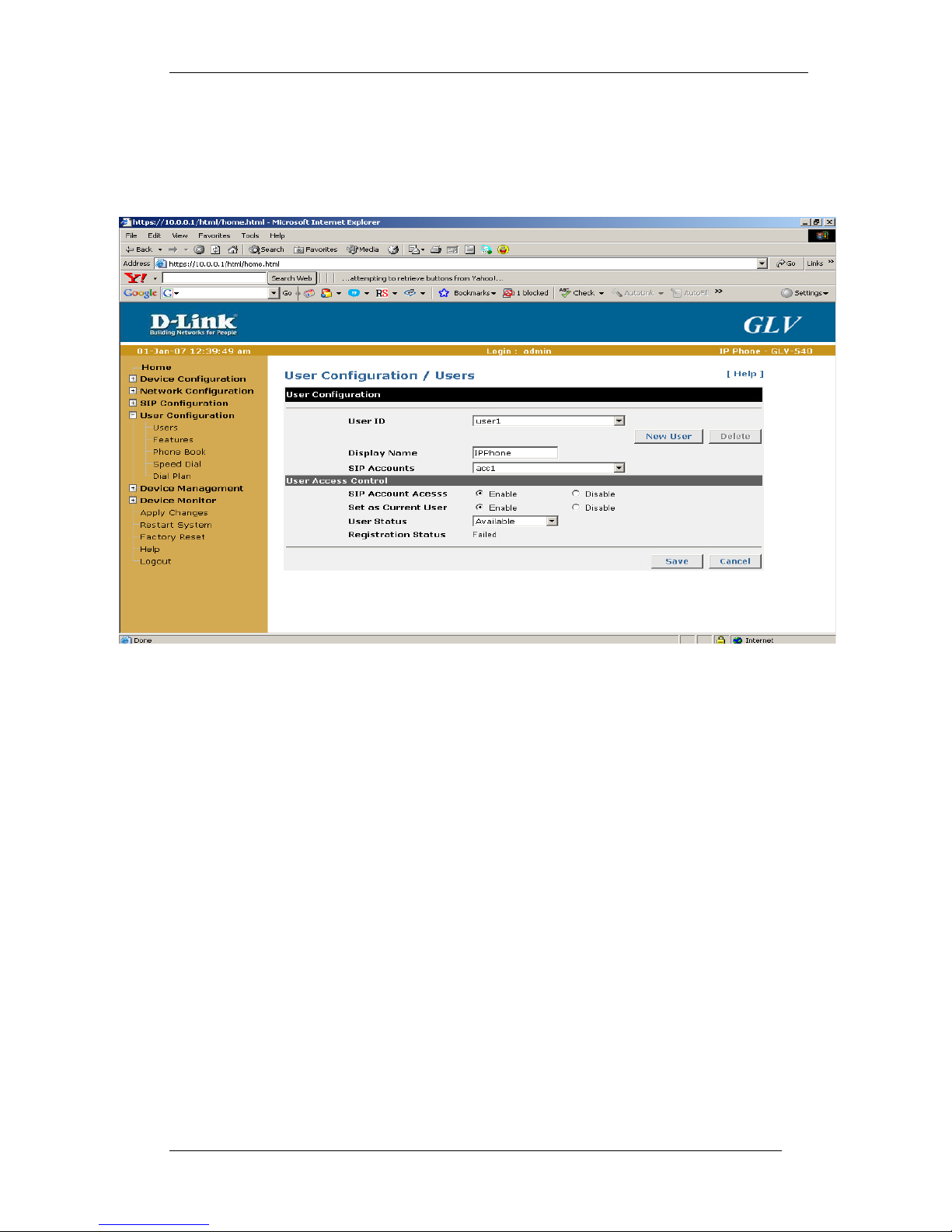
To add a User profile, Click on the “User ConfigurationUsers” link. Add a
new user and configure the user profile parameters: - User ID, SIP
accounts, display name, user profile access password, user access to SIP
account configuration, user status.
Figure 8: User Configuration
17
Page 18
GLV-540 User Manual
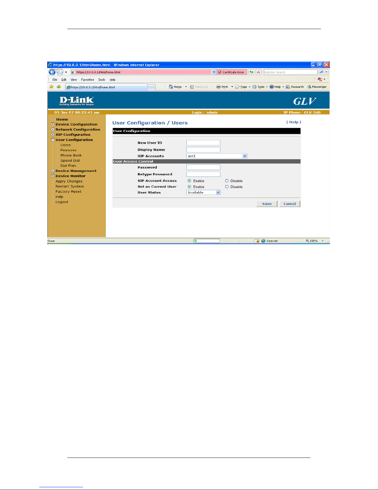
Figure 9: User Configuration (New User)
Click on “Save” button.
18
Page 19
GLV-540 User Manual
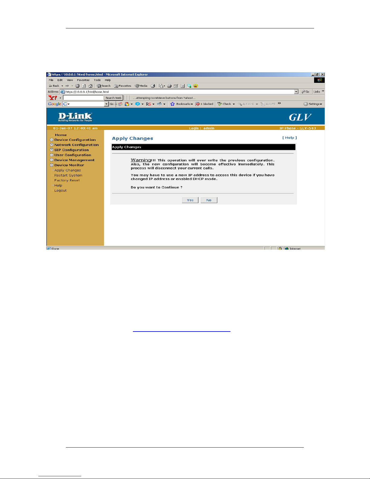
Click on the “Apply Changes” link and “Yes” option so that modified
configuration is saved permanently and becomes effective.
Figure 10: Apply Changes
The system will now restart and come up with the new configurations. Access
the IP phone web interface by specifying the newly configured IP address in
the web browser’s URL. When the IP Phone is ready for use, the LCD screen
shows Figure 27: Idle Screen and plays dial tone on going OFF HOOK.
The following parameters should be configured for proper functioning of the IP
phone. Other parameters can use default values.
Refer to the Section 6: Configuration Guide for the complete list of
configurable parameters.
o IP Address configuration
o Phone number (it should be unique number within SIP proxy domain)
o User name and password (used for authentication with SIP server)
o SIP proxy address
Save these parameters after modification from the LCD or the Web browser.
These parameters will be saved to non-volatile memory and the IP phone will
restart. Now the IP phone will try to register with the SIP proxy server. On
going Off hook, a dial tone will be played on any of the three Handset/
Headset/ Speaker interfaces if the phone has registered successfully
otherwise, an error tone will be played.
19
Page 20
GLV-540 User Manual
4.3 Configuring through LCD
The GLV can be configured through the LCD and Keypad Interface. For
Navigation across different menus use Left Navigation Key and Right Navigation
keys, within the menu to select different menu elements, use up & down
Navigation keys. To begin configuration through LCD, Press the “MENU” button
on the keypad. The LCD screen will then display the following menu. Use the
navigation up / down arrow buttons, select Admin and press the “SELECT” soft
key.
03 Jul 07 GLV 12:16:57
1. Admin
2. user 1
Select Exit
Figure 11: Menu Login Screen
Step1:
System will ask for password. Enter the admin password (default: 123)
using the phone keypad. Press the Enter key, if correct password is entered,
then the administrator configuration menu is displayed.
< Information >
1. Device Name
2. MAC address
3. IP address
Select Exit
Figure 12: Information Screen
Note: Same login password is used configuring phone through LCD & Web.
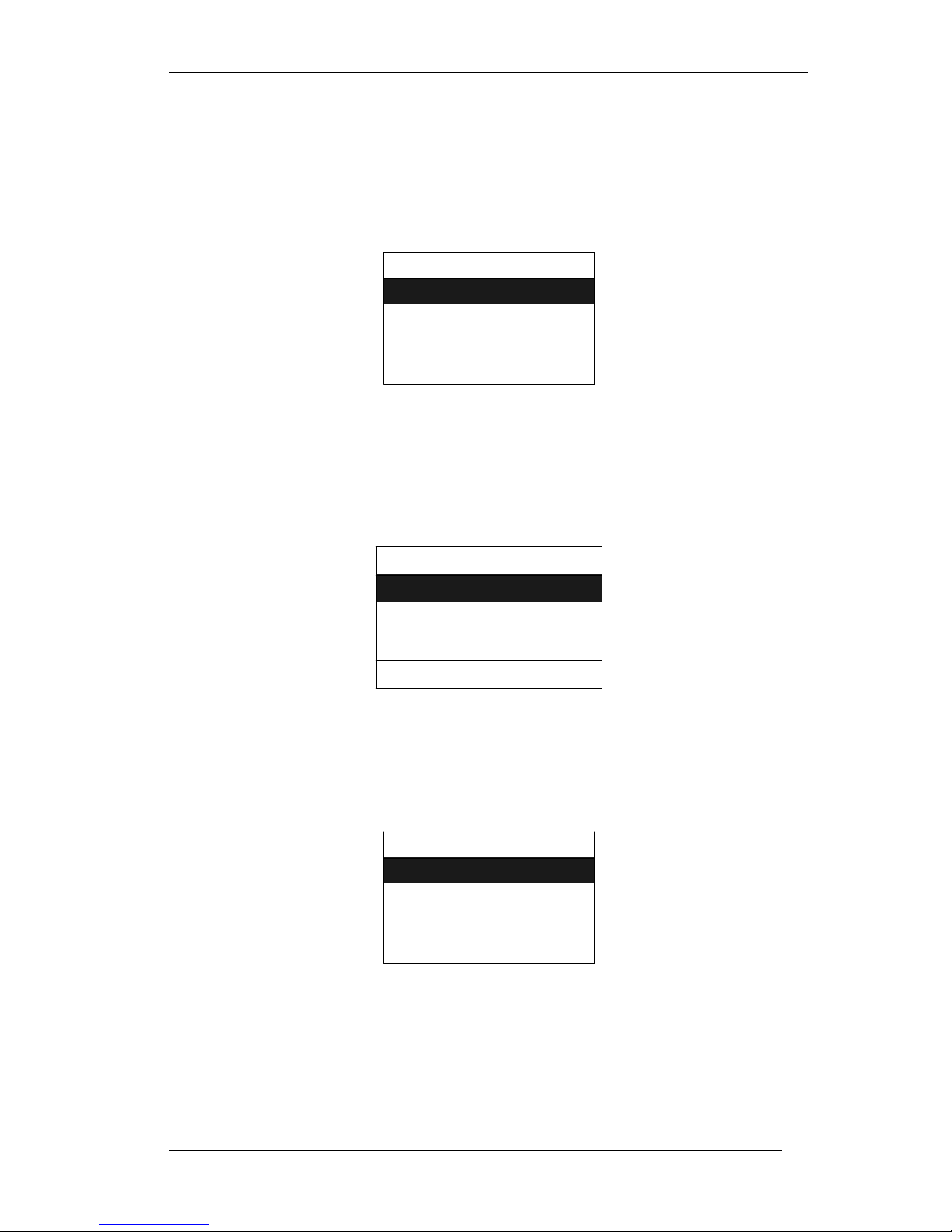
Step2:
Use the right navigation arrow to go to “IP Settings” screen as shown below.
< IP Settings >
1. IP Mode
20
2. IP Parameters
3. DNS Server
Select Exit
Figure 13: IP Settings
Page 21
GLV-540 User Manual
Now use the navigation arrow up / down to highlight the IP Mode selection.
Press the soft key labeled “Select” to confirm the selection.
IP M ode
1. S tatic
2 . DH C P
3 . PP P o E
Se lec t Return
Figure 14: IP Mode
After selecting the IP mode, press the “Return” soft key to return to “IP
Settings screen”. Now select the “IP Parameters” option from “IP Settings”
screen to configure the IP address, Netmask and default gateway.
Use the phone key pad to enter the IP address to be assigned to the IP Phone
and press the soft key labeled “Save”.
IP Address
Enter the IP Address
10.0.0.1
Save Clear Next
Figure 15: IP Address
Use the phone key pad to enter the Net Mask and press the soft key labeled
“Save”.
Net Mask
Enter the Net Mask
255.0.0.0
Save Clear Next
Figure 16: Net Mask
Use the phone key pad to enter the Default Gateway IP address and press the
soft key labeled “Save”.
Default IP Gateway
Enter the IP Gateway
10.0.0.6
21
Save Clear Return
Figure 17: Default Gateway IP Address
Page 22
GLV-540 User Manual
Note
:
To clear any data use the “Clear” soft key. Use the “Next” soft key to go to
next parameter without saving the change for the displayed parameter.
Step3:
Again press the right navigation button to move to “VoIP Settings” screen and
Press the soft key labeled Select to go to “User Configuration” page.
< VOIP Settings >
1. SIP User Configuration
2. SIP Server Configuration
3. Voice Mail Settings
Select Exit
Figure 18: VoIP Settings
User Configuration
SIP User Name is
101
Save Clear Next
Figure 19: VoIP Settings (SIP User Name)
Enter SIP user name using phone keypad, press “Save” soft key.
User Configuration
SIP Phone Number is
101
Save Clear Next
Figure 20: VoIP Settings (SIP Phone Number)
Enter SIP Phone Number using phone keypad, press “Save” soft key.
22
User Configuration
SIP Auth Name is
101
Save Clear Next
Figure 21: VoIP Settings (SIP Auth Name)
Page 23
GLV-540 User Manual
Enter SIP Auth Name using phone keypad, press “Save” soft key.
User Configuration
SIP Auth Password is
101
Save Clear Return
Figure 22: VoIP Settings (SIP Auth Password)
Enter SIP Auth Password using phone keypad, press “Save” soft key. Press
“Return” soft key to go to “VoIP settings” page without saving changes done
to Sip Auth password.
Note:
To clear any data use the “Clear” soft key. Use the “Next” soft key to go to
next parameter without saving the change for the displayed parameter.
LCD will return back to “VoIP Settings” menu. Scroll down to “Sip Server
Configuration” using the UP/DOWN navigation keys, Press “Select” soft key.
Server Configuration
SIP Server address is
Save Clear Next
10.0.0.5
Figure 23: VoIP Settings (SIP Server Address)
Enter SIP Server address using phone keypad, press “Save” soft key.
Server Configuration
SIP Server Port is
5060
Save Clear Next
Figure 24: VoIP Settings (SIP Server Port)
Enter SIP Server Port using phone keypad, press “Save” soft key.
Server Configuration
Enable Outbound Proxy?
Yes No
23
Page 24

GLV-540 User Manual
Figure 25: VoIP Settings (Outbound SIP Proxy)
Select “Yes” soft key if outbound proxy is present, and configure the
Outbound Server address and Outbound Server Port on the next screen which
appears on the LCD. Press “Return” soft Key to return to “VoIP Settings”
Page; else Press “No” soft key to return to “VoIP Settings” page.
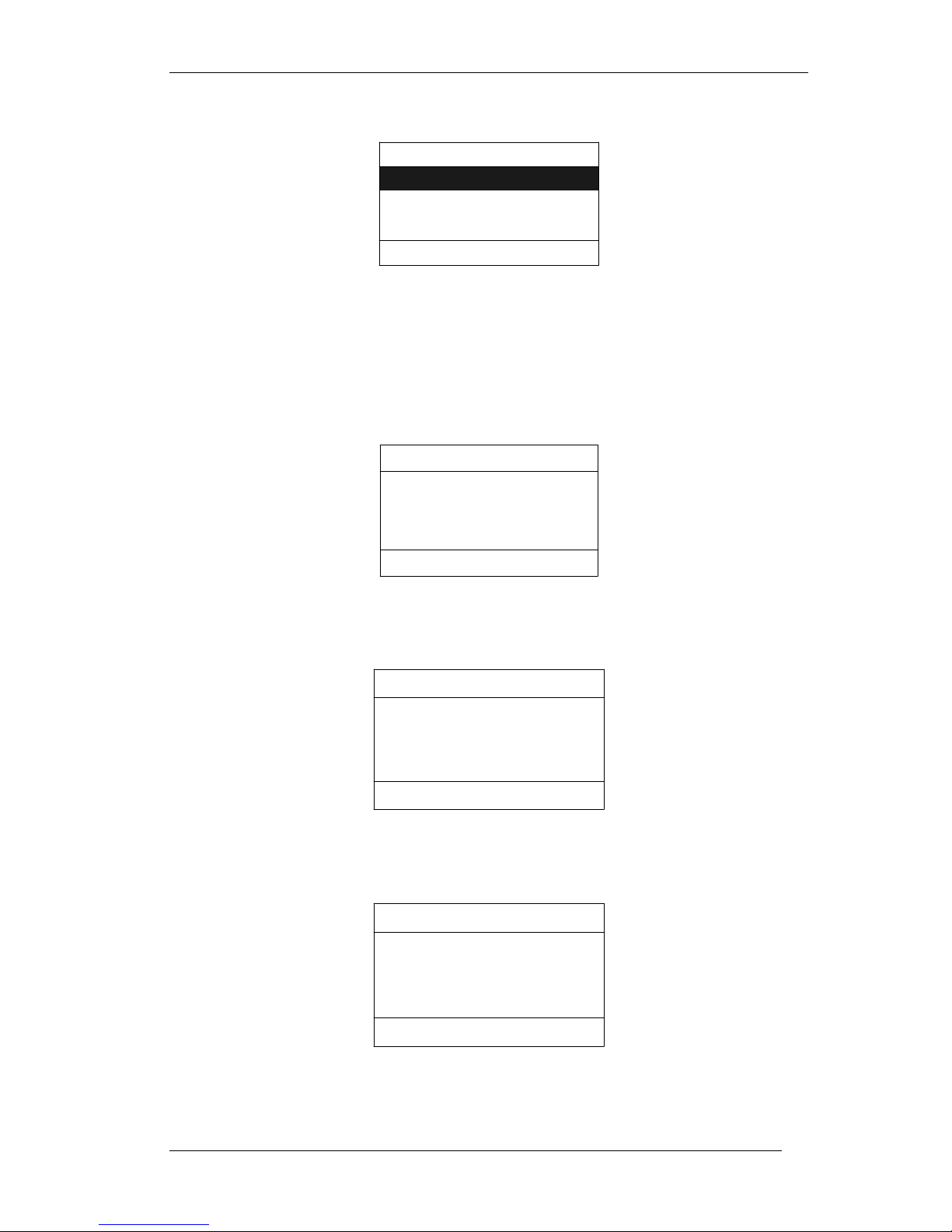
Step4:
Press the “Exit” soft key to move to the exit screen.
Exit Configuration
Do you want to save your
changes to Configuration ?
Yes No Cancel
Figure 26: Exit Screen
Step5:
Press the “Yes” soft key to permanently save the phone configuration. Phone
will restart and come up with the new configuration.
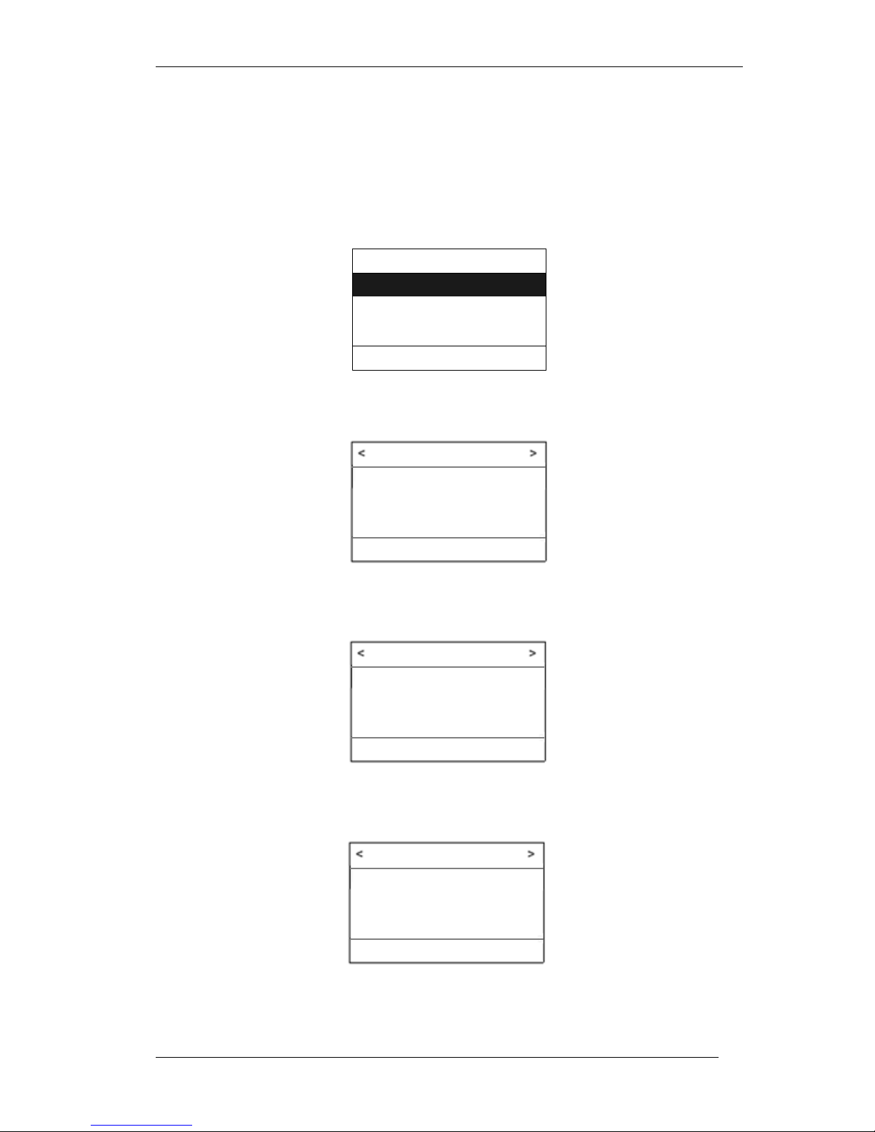
When the IP phone is ready for use the following screen will be displayed.
03 Jul 07 GLV 12:16:57
IP Phone user1
Welcome
NewCall PBook Redial
Figure 27: Idle Screen
Note:
o
A beep sound will be played through the speaker, once the phone
successfully registers with the configured SIP Server.
o
The IP phone configuration cannot be simultaneously accessed through the
Web and LCD. Please logout from the Web browser before accessing the
configuration menu through the LCD.
o
If the IP Mode was set to DHCP / PPPoE, then to view the IP address
assigned to the phone, log in to Menu configuration and select the IP
Address option in the Information screen (
Figure 12: Information Screen
). This
will display the new IP address of the system. This IP address can be used
to access the IP Phone configuration through the web browser.
24
Page 25

4.4 Initiating an Outgoing Call
GLV-540 User Manual
4.4.1
4.4.2
Off hook dialing
To use off hook dialing, Lift the Handset or Press the Speaker key or Press
Headset key or Press any Line key. The LCD will display the following menu:-
03 Jul 07 GLV 12:16:57
IP Phone user1
Enter the Number
SpeedDial PBook Redial
Figure 28: Off Hook Dialing
o
Now enter the destination phone number using the keypad.
o
The IP Phone will initiate a call to the destination after inter digit
timeout or dialing of the dial termination character.(Default : #)
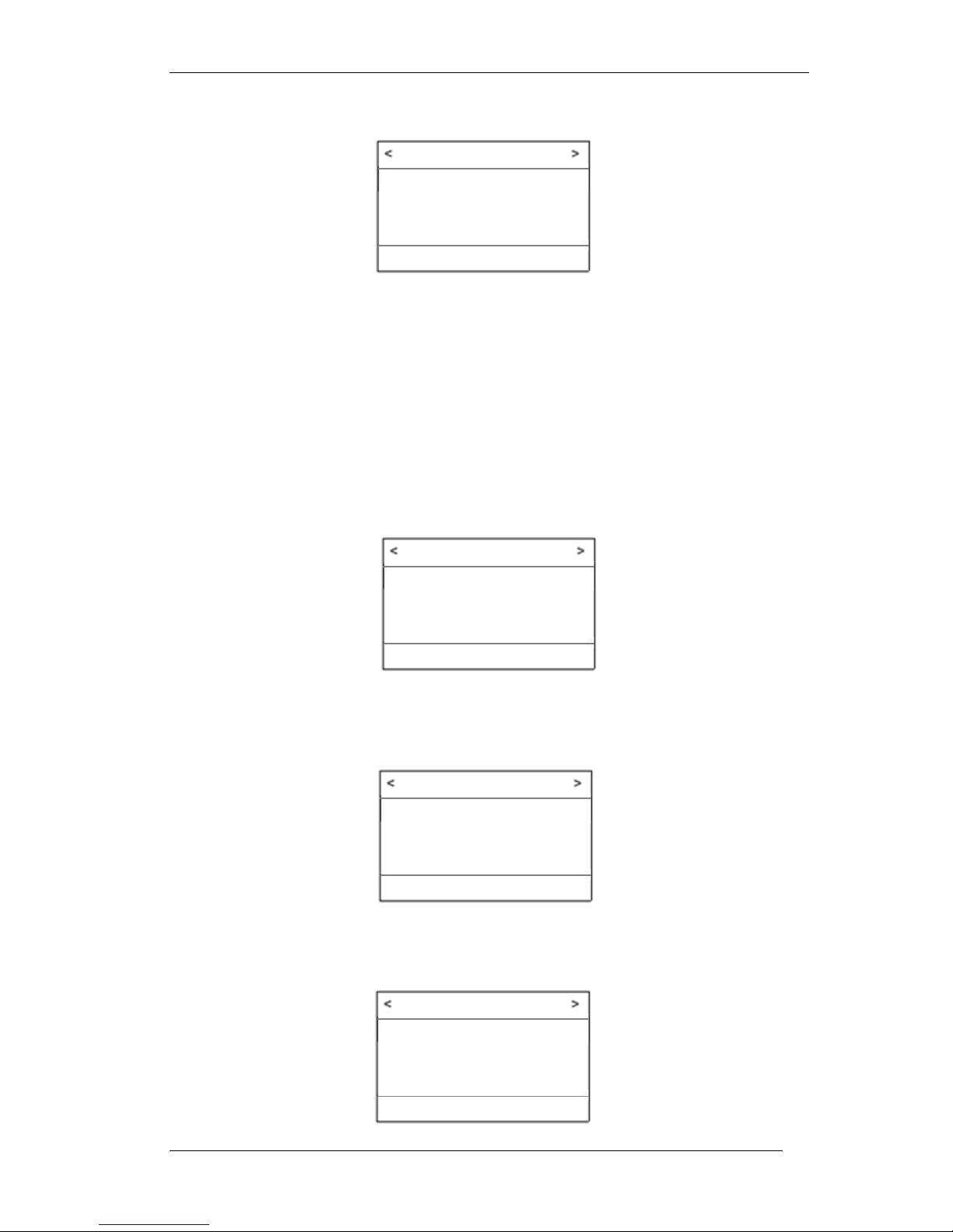
On Hook dialing
To use on hook dialing, enter the destination phone number when the IP
phone is idle (No Line is in use). The LCD will display the following menu:-
03 Jul 07 GLV 12:16:57
IP Phone user1
Enter the Number
520
Call Clear Cancel
Figure 29: On Hook dialing
o
Now Press the soft key labeled “Call” to initiate the outgoing call.
o
To edit the entered phone number, use the soft key labeled “Clear”.
o
To cancel the call, use the soft key labeled “Cancel”.
Note:
On hook dialing allows you to leisurely enter the phone number
without having to enter the digits before the inter digit timeout
occurs. This is particularly useful for dialing numbers that need
looking up from a directory.
Dialing the dial termination character (default: #) can also be used
to initiate the outgoing call.
If no soft key is pressed for 3 minutes of dialing a number then the
phone will clear the dialed number and return to idle screen.
25
Page 26

GLV-540 User Manual
4.4.3
4.4.4
Dial using Phone book
To make calls using the Phone Book, press the soft key labeled “PBook”.
The LCD will display the following menu:-
< Phone Book 1/10 >
1. Bob
2. Alice
3. John
Call Details Cancel
Figure 30: Dial using Phone Book
o
To select a Phone book entry; use the up/ down navigation buttons.
o
Now Press the soft key labeled “Call” to confirm the selection and
initiate the call
o
Phone book entries can also be selected by pressing the number
displayed on the left of the phone book entry. For example press digits
10 to select the 10th phone book entry
.
.
Dial using Speed Dial
Speed Dialing through Keypad:
o
To use Speed Dial, simply dial number of the speed dial entry.
For example dial 4 to initiate a call to the destination phone number
configured in the 4th Speed dial entry.
Speed Dialing through LCD & Keypad:
o
To use Speed dial by viewing the contents of the speed dial list:
o
Lift the Handset or Press the Speaker key or Press Headset key or
Press any Line key. The LCD will then display the off hook dial menu as
shown in
o
Now press the soft key labeled “SpeedDial”, The LCD will display the
following menu:-
Figure 28: Off Hook Dialing
.
< Speed Dial 3/100 >
o
To select a Speed Dial entry; use the up/ down navigation buttons.
o
Now Press the soft key labeled “Call” to confirm the selection and
initiate the call.
Note:
In the title of LCD menu “<” and “>” indicate presence of other menu
options for navigation through arrow keys.
For example: In Speed dial menu press left arrow key to navigate to
Phone book menu or right arrow key to navigate to Missed calls menu.
26
1. Jack
2. Tom
3. John
Call Details Cancel
Figure 31: Speed Dial
Page 27

GLV-540 User Manual
4.4.5
4.4.6
Redial
To redial a number, press the soft key labeled “Redial”.
The LCD will display the following menu:-
< Dialed Calls 2/100 >
1. Carol
2. Alice
3. John
Call Details Cancel
Figure 32: Redial
o
To select a Dialed call entry; use the up/ down navigation buttons.
o
Now Press the soft key labeled “Call” to confirm the selection and
initiate the call.
Note:
Call will be automatically initiated to the last dialed entry if no key is pressed
for sometime after opening dialed call entry.
IP Address dialing
IP Address dial features can be used to communicate between the GLV and
other SIP aware devices such as VoIP Phone or VoIP Gateway.
This communication requires the specified target IP address to be accessible
from the GLV. For example:
o
GLV IP phone and the target SIP device are having Public/Global IP
address.
o
GLV IP phone and the target SIP device are connected to the same
LAN.
To initiate a call using IP Address dialing enter the IP address of the target
device. For example: Enter 192.168.10.192:5064 to call device with IP
address “192.168.10.192” and port “5064”
Note:
To dial the IP address using special characters change the key mode to
Alphanumeric, refer section 5.1.14 Key Mode.
To dial the ‘.’ character, repeatedly press the numeric key ‘1’ or ‘0’ till the ‘.’
character is displayed on the LCD. Similarly to dial the ‘:’ character press the
numeric key ‘1’ or ‘0’. Please refer to section 7.3 for more details.
GLV supports the following IP Address dialing formats:
o
“IP address” example: 192.168.10.192
o
“IP address : Port” example: 192.168.10.192:5063
o
“user@IP address” example: 1234@192.168.10.192
o
“user@IP address : Port” example: 1234@192.168.10.192:5063
GLV supports dialing by domain name, following are the supported formats:
o
“Domain Name” example: example.com
o
“user@Domain Name” example: 1234@example.com
27
Page 28

GLV-540 User Manual
4.4.7
4.4.8
E.164 Calls
E.164 or ENUM (Electronic Number Mapping) facilitates calling VoIP users
from IP and PSTN networks. To make a call to an E.164 number enter the
PSTN number in the following format:(Maximum 30 digits)
+(Country Code) (Area Code) (Telephone Subscriber number)
For example: +918026788345
It is also possible to configure the Area code in GUI. User can configure
“9180” as area code and dial +26788345. The phone will prefix the area code
and dial out. There is an enable/disable option in GUI. If disabled, phone will
dial +26788345 directly.
Note: To dial the ‘+’ character, repeatedly press the numeric key ‘1’ or ‘0’ till
the ‘+’ character is displayed on the LCD, also keypad should be in
Alphanumeric mode.
Note:
To dial the IP address using special characters change the key mode to
Alphanumeric, refer section 5.1.14 Key Mode.
Call using a specific SIP Account
GLV supports selecting a specific user profile while initiating an outgoing call.
The SIP account associated with the selected user profile will be used to make
the call.
To initiate an outgoing call through a specific SIP account, select a user profile
associated with that SIP account: - (Any available Line can be used by all the
configured user profiles)
o
Select any available line by pressing the Line Key (L1/ L2 / L3)
o
Press the “USER” key on the keypad
o
Select a user profile from the list of Users displayed on the LCD.
o
Dial the destination phone number
Note:
Please read sections 5.1.1, 5.1.3, 5.1.4 and 5.1.2 of this user manual for
more information on multiple user and SIP account features.
28
Page 29

4.5 Answering an Incoming Call
GLV-540 User Manual
4.5.1
Single Incoming Call
When an Incoming call arrives, the Line LED will blink and GLV will play a ring
tone. The LCD will display the following menu:-
03 Jul 07 GLV 12:16:57
From “Bob” 2674123
To IP Phone user1
Answer Forward Reject
Figure 33: Answering an incoming call (single)
The incoming call can be answered by any of the following ways:
o
Lift the Handset
o
Press the speaker button
o
Press the headset button in case headset connected.
o
Press the Line key for which the LED is blinking.
o
Press the soft key labeled “Answer”
To reject the incoming call, press the soft key labeled “Reject”
To forward the incoming call, press the soft key labeled “Forward”, enter the
number to which the call should be forwarded and again press “Forward”.
Note:
When an incoming call arrives, if user is not in idle screen (i.e., user is parsing
phone book or speed dial, or in function screen, or MWI screen or Help screen
or Menu screen) phone will not show the incoming call screen, but will give
indication by ring and Line LED blink. User can press line key to get the
incoming screen or directly go OFF Hook (handset/spkr/headset) to connect
the call.
4.5.2
Multiple Incoming Calls
If there are more than one Incoming calls that are yet to be answered, the
respective Line LED’s will blink and GLV will play a ring tone. The LCD will
display the information shown in Figure 31. To select one of the calls, press
the corresponding Line key, the LCD will then display information about the
selected call.
To answer a selected call; use any of the following ways:
o
Press the Line key again.
o
Press the soft key labeled “Answer”
o
Lift the Handset
o
Press the speaker button
o
Press the headset button in case the head set connected.
Note:
Once a call has been selected by pressing the Line key, if none of the above
actions is performed within a specified period of time, then the selected call
will automatically be answered through the speaker.
For example:
o
An incoming call arrives at GLV say on Line 1, the L1 LED will blink and
ring tone is played. The LCD will display the information about call on
Line 1 as shown in Figure 33.
29
Page 30

GLV-540 User Manual
o
Now if another incoming call arrives at GLV say on Line 2, the L2 LED
will blink. To select and view information for call on Line 2, press the
Line key labeled L2.
The LCD will display the following menu (for call on L2):-
03 Jul 07 GLV 12:17:10
From “Alice” 2674358
To IP Phone user1
Answer Forward Reject
Figure 34: Answering an incoming call (multiple)
o
To answer this call press the soft key labeled “Answer”, otherwise to
select call on Line 1, press the Line key labeled “L1”
Note:
If an incoming call arrives while the LCD is displaying phone book or speed
dial entries, then new call indication is not provided on the LCD.
A line LED will blink to indicate the incoming call.
To answer this call, either off-hook or press the line LED to select the line and
then answer the call as given in section 4.5.1 “Answering Single Incoming
call”.
Note:
The phone cannot be used to initiate calls, when “MENU” configuration is
being used.
Menu configuration is accessed by pressing the “MENU” key when phone is
idle.
When two available users are using the same VOIP account and there is
incoming call to any of the user, the incoming call will be mapped to the first
user and LCD always displays the call for that first user.
30
Page 31

5 Features
5.1 Phone Features
GLV-540 User Manual
5.1.1
Multi User
GLV can support up to 5 independent user profiles and 5 SIP accounts. A user
profile identified by a unique “User Id” contains user information so as to
personalize the IP phone for a particular user. Features like Phone book,
Speed dial, Caller Id, Ring tone type and many more can be independently
configured for each user profile.
A SIP account identified by a unique “Account Id” contains information about
the SIP server address, authentication, Voicemail, MWI etc. A SIP account can
be associated with zero or more user profiles; however a user profile can be
associated with at most one SIP account.
GLV-540 can be operated by one or more user(s) at any given point of time.
Each user is associated with a user profile and this user profile can be
associated with an SIP account. Calls initiated/received for the selected user
will use the associated user profile & SIP account. One SIP account can be
linked with one or more user profiles. A user profile can be associated with
only one user, it cannot be shared.
The following combinations of user profiles and SIP accounts are possible:
o
Each user has its own user profile and SIP account.
User Profile
(User 1)
SIP Account
(Account 1)
User Profile
(User 2)
Figure 35: Individual User profiles and SIP Accounts
o
Multiple users share single SIP account, but each user has a separate
user profile.
SIP Account
(Account 2)
User Profile
(User 1)
SIP Account
(Account 1)
User Profile
(User 2)
Figure 36: Multiple User profiles sharing a SIP Account
31
Page 32

GLV-540 User Manual
5.1.2
5.1.3
User Mode
GLV-540 can operate in any one of the following modes:
o
Single User Mode
o
Multiple User Mode
Single User Mode: In this mode only one User profile can operate at a time.
Only one user profile can have user status as AVAILABLE and the same user
will be the default/current user. Calls can be initiated and received only for
the default user. All other users will be having user status as UNAVAILABLE.
Multiple User Mode: In this mode GLV can be used by more than one user
profile simultaneously. Multiple user profiles can have user status as
AVAILABLE and one of the AVAILABLE users can be set as default/current
user. Calls can be initiated and received for all user profiles that have user
status AVAILABLE.
User Status
A configured user profile can be used only if its user status is “AVAILABLE”.
User status can have either of the following values:
o
“AVAILABLE”: user profile with user status “AVAILABLE” can be used
to initiate and receive calls. Phone will initiate SIP registration for
“AVAILABLE” users only.
o
“UNAVAILABLE”: user profile with user status “UNAVAILABLE” cannot
initiate or receive calls.
User Status of a user profile can be modified either through Web or LCD
interface. Logging into a user profile through the LCD will update user status
to “AVAILABLE”. Similarly logging out of a user profile through LCD changes
the user status to “UNAVAILABLE”.
Note:
Logging in through Web browser does not change the user status. To change
user status through the Web, update user status field in “User configuration”
web page and save the phone configuration.
5.1.4
Default User
One of the configured user profiles needs to be set as the default/current user
profile. All outgoing calls will use default/current user profile. All information
displayed on the LCD will be with respect to Default user profile, i.e. Phone
book, speed dial etc.
For example: Consider a user profile “user 1” as the default user profile, it is
associated with SIP account “Account 1”. When any line (L1/ L2 / L3) is
selected, then the call is made using the SIP server configured in SIP account
“Account 1”.
To set the default/current user profile:
o Press the “USER” key on the keypad, when the phone is idle (not in
call) and the handset is on-hook.
o Select a user profile from the list of Users displayed on the LCD.
Enter the selected user profile password to confirm the selection of the
default/current user profile.
Note:
Selecting a user profile as default/current user will automatically set the
corresponding user status to “AVAILABLE”
32
Page 33

GLV-540 User Manual
5.1.5
5.1.6
User Privilege
GLV defines two privilege levels for its users.
o
Administrator: A user with this privilege can modify system and
individual user configuration.
o
User: A user with this privilege can view system parameters but modify
only self user profile and SIP account parameters.
Note:
Administrator privilege does not have a user profile and SIP account
associated with it. Consequently calls cannot be initiated or received by
administrator. A user privilege is required to initiate and receive calls.
Administrator privilege provides access to entire phone configuration
parameters through LCD and GUI.
Please refer to section 5.1.12 for more information on access restrictions that
apply to user and admin privilege.
The default password for User to login through GUI or LCD is “123”.
Multi Line
Multi Line feature of GLV-540 facilitates initiating and receiving multiple calls.
GLV has three Line buttons (L1, L2 and L3). Each line can support at most one
call. Line buttons have a LED, which will glow during a call and blink upon
arrival of an incoming call.
At any instant of time, only one Line can be active (Call on the Line is
connected and media / voice is flowing), all other Lines will be inactive (line is
not in use or Call on the line is placed on Hold). The exception is 3-WayConference, where in both the lines participating in the conference are active.
Note:
To Select a Line (LI / L2 / L3), press the associates line button. Taking the
Handset/ Headset/ Speaker when the phone is idle (not in call) will select any
one of available lines.
Note:
Incoming calls for a configured SIP account will use the user profile associated
with that SIP account. Incoming calls will attempt to use any of the available
Lines (L1 /L2 /L3). .
5.1.7
5.1.8
Auto Configuration
This feature helps to configure the GLV-540 automatically. Auto Configuration
can be either performed with DVX-1000(D-Link IPPBX) or with TFTP server or
with HTTP or HTTPS. The provision server address can be configured statically
or obtained from DHCP response () or sip server (). Auto Configuration can be
scheduled to do Once or periodically (configurable interval, in days) or after
each Factory Reset.
Configuration Backup and Restore
GLV-540 provides functionality to backup and restore phone configuration
through web and LCD. The configuration parameters that can be modified
through configuration back and restore depend on the user privilege.
Based on the privilege of the logged in user, the following operations are
performed:
33
Page 34

GLV-540 User Manual
o
Administrator: Administrator privilege allows to backup, all system and
user related configuration files; these will be zipped into a single file
named “CfgBkup.zip”.
This zip file will contain a directory “CfgSys” which contains:
sysconfig.xml (system configuration file),
All account configuration file (acc_xxx.xml, xxx will be the
account id),
all user profile files (prof_uid.xml, uid is the user id),
Phone book lists of all users (pb_uid.csv, uid is the userid),
Speed dial list of all users (sd_uid.csv),
Dial plan of all users (dp_uid.csv),
Dialed call of all users (dc_uid.csv),
Received call of all users (rc_uid.csv),
Missed call of all users (mc_uid.csv).
For performing configuration restore a zip file, any name (say
“CfgBkup.zip”) with similar content is expected (ie all files should be in
a directory which is zipped). All the above mentioned files will over
write the corresponding files in the phone.
Note:
The files sysconfig.xml, all user profile and account
configuration files must be present in “CfgBkup.zip”. Otherwise
configuration restore operation will fail.
The remaining files like phone book, speed dial, dial plan, dialed
calls, received calls, missed calls list etc are optional and may
not be present in “CfgBkup.zip”.
Call History information in dialed/ received/ missed calls will not
be restored in configuration restore operation.
Creating Configuration Restore package:
o
Copy all files, sysconfig.xml, acc_xxx.xml etc to a
directory. No restriction on Directory name.
o
Zip the directory and use it for restore. No restriction on
zip file name.
o
User: User privilege allows to backup system configuration, the
selected user’s profile, associated account configuration and
miscellaneous files. These will be zipped into a single file named
“user1Config.zip”.
This zip file will contain:
sysconfig.xml (system configuration file),
user profile files (prof_uid.xml, uid is the user id),
associated account configuration file (acc_xxx.xml, xxx will be
the account id)
Phone book lists of all users (pb_uid.csv, uid is the userid),
Speed dial list of all users (sd_uid.csv),
Dial plan of all users (dp_uid.csv),
Dialed call of all users (dc_uid.csv),
Received call of all users (rc_uid.csv),
Missed call of all users (mc_uid.csv).
For performing configuration restore a zip file, any name (say
“user1Config.zip”) with similar content is expected. All the above
mentioned files except the account configuration file will over write the
corresponding files in the phone.
Note:
During configuration restore, don’t modify any parameters in the configuration
files without full knowledge.
34
Page 35

GLV-540 User Manual
5.1.9
5.1.10
Factory Reset
GLV-540 allows Factory Reset of complete System or All Users or for
Individual Users.
In system Factory Reset all the system parameters will be reset to the factory
default values. All existing users and account will be removed and only default
user and account will remain.
In case of All Users Factory Reset, all users profile parameters will be set to
default values. Parameters of the Account associated with the users are not
modified. The user status for all users except the default user is changed to
“NOT AVAILABLE”.
During Individual user Factory Reset, only that users profile parameters will
be reset. In this case also associated account’s parameters are not modified.
Software Upgrade
GLV-540 provides a facility to upgrade the software through web and LCD.
When initiating upgrade through Web, it can be configured to perform from a
TFTP / HTTP server. User can also configure the server address and Port
statically or to get these parameters from a DHCP server (This requires the
phone to be in DHCP mode). Upgrade can be scheduled to occur once or
periodically (configurable interval in number of days) or after each Factory
Reset.
Software upgrade can also be initiated through LCD. In this case the existing
configuration for software upgrade parameters is utilized. The option to
configure software upgrade parameters through LCD is not available.
To perform software upgrade a TFTP/HTTP server is required to be setup.
This server will hold the files that will upgrade the existing software.
To initiate software upgrade through the Web
o
Click on the Device Management->Software link in the IP Phone GUI.
o
Click on Enable radio button to enable software upgrade configuration
o
Select server type as TFTP or HTTP.
o
Select Server address option “Static”.
o
Enter the IP address and port where TFTP/HTTP server is running.
TFTP default port is 69 and HTTP default port is 80.
o
When the server type is HTTP, proxy server address, port, user name
and password can be configured.
o
Enter the software upgrade filename.
o
Select upgrade schedule as “Once Now”
o
Click on “Save” and Apply Changes.
Note:
Once the software upgrade is started all line LED’s will start blinking to
provide a visual indication for software upgrade in progress.
The phone cannot be used to initiate or receive calls while software
upgrade is being performed.
The software upgrade status can be viewed through Web on “Device
MonitorUpgrade History” page.
While going for Software upgrade when system configuration parameters are
not available, software upgrade would be initiated with default values. Phone
uses default values like for IP address value shall be “10.0.0.1”, Netmask as
35
Page 36

GLV-540 User Manual
“255.0.0.0”, TFTP address shall be “10.1.1.254”, Server Type as “TFTP”,
Server Port 69, file Name as “glv_upgrade”.
Note:
For Windows, Preferred TFTP Server can be " TFTPD32” - version 2.80; for
this server, set the options "Timeout = 10" and "Max Retransmit = 20".
For Linux, use the Standard TFTP Server.
5.1.11
5.1.12
Help
GLV-540 provides help on both Web and LCD. Context sensitive help is
provided on each web page. The help link will take user to the help section of
concerned page. The Help link on the left tree points to the Help index, from
which user can access the help for any page.
To view help messages while accessing the phone through the LCD, press the
Help button to display corresponding the help text messages on LCD.
Access Control
GLV supports two level of access privilege– Admin level and User Level. The
privilege level is identified based on username and password entered while
logging onto the GUI.
Admin can edit all the fields on all pages, perform software upgrade, entire
configuration backup and restore, system factory reset, add / delete / view
any user configurations, feature configurations, Add / delete / view any SIP
Account and can change any of the user or admin passwords.
Other users can view the field configuration on all pages and only edit their
user configurations or user features, user configuration upload and download
and can only change their password. One can modify the password of
administrator and user based on your login privilege. Changing the username
is not allowed for both user and Admin
Note:
Default admin level username: “admin” and password: “123”
Default user level username: “user1” and password: “123”
5.1.13
User Lock
GLV supports Locking / Unlocking of user profiles. User Lock prevents the
phone from making calls using a locked user profile but can receive calls with
limited call features.
For example:
If user profile (user 1) is locked, then outgoing call cannot be initiated by user
1. Incoming calls for user 1 are allowed, but these advanced call features such
as Hold, Transfer, Conference cannot be initiated.
Any User profile can be Locked/Unlocked through the “User Configuration->
User” Web page. The default/current user can be Locked/Unlocked through
LCD.
To lock default user through LCD, press the “Function Key” (P1), select the
“Lock” option. Enter the default user‘s password to confirm user lock. The
same procedure is used to unlock the default user through LCD.
Note:
Dial tone will not be played if the default user has been locked.
36
Page 37

GLV-540 User Manual
Locked user profiles will not be displayed on LCD while selecting user
profile for initiating call, initiating Transfer etc.
Another user profile can be selected as default user, while the existing
default user has been locked.
One can continue to make call with user profiles that are unlocked.
5.1.14
5.1.15
5.1.16
Key Mode
Key Pad Mode or Key Mode helps user to select NUMERIC dialing or
ALPHANUMERIC dialing option.
User can select this option from LCD using function key. Key pad mode is
selectable only for dialing screens like off hook/on hook dialing screen or
dialing the transfer target number, dialing the conference number or dialing
the forward number.
By default the mode is set to NUMERIC dialing.
Country Code
GLV supports playing tones that are specific to a country. Select a Country
Code to set the appropriate tones for the specified country. To manually
configure the Tone parameters select Country Code as “OTHERS”.
Note:
Upon Changing the Country Code, the phone will reboot. All existing calls will
be terminated before rebooting the phone.
Downloadable Tones
GLV supports downloading of custom tones. The tones can be downloaded
through Web interface, this operation requires ADMIN privilege. At any instant
of time only one audio file is available for each Tone, downloading the same
tone again would replace the existing audio file.
A custom tone can be downloaded for the following Tones:
o
MOH (Music on Hold)
o
MWI (Message Waiting Indication)
o
Ring Tone (Ringer tone)
o
Dial Tone (Tone played upon selecting Handset/ Headset/ Speaker)
o
Busy Tone (Tone played upon receiving busy status for a outgoing call)
o
Ring back Tone (Tone played upon receiving alert status for a call)
o
Progress Tone (Tone played during a call establishment attempt)
o
Error Tone (Tone played upon failure of a call establishment attempt)
To use custom tones like “MOH’, “MWI”, “Ring Tone”, you can download them
directly by using the below mentioned method and these tones are not
specific to any country code.
To use custom tones for tones like “Dial Tone”, “Busy Tone”, “Ring back
Tone”, “Progress Tone”, “Error Tone”, you have to configure your country
code as “Others”.
To download a single tone through the Web
o
Zip the audio file, click on the “browse” button to locate the zipped file.
o
Select the tone to be updated from the above list and click on
“download” button.
37
Page 38

GLV-540 User Manual
To download all tones through the Web
o
Place all audio files in a folder named “Tone” and zip the folder
o
Click on the “browse” button to locate the zipped file.
o
Select the “ALL” option from the list of tones and click on “download”
button.
Example of Tone directory contents:
o
Tone
BusyTone.wav
DialTone.wav
ErrorTone.wav
MOHTone.wav
MWITone.wav
ProgressTone.wav
RingBackTone.wav
RingTone.wav
From preparing .wav files using Windows, you can use standard sound
recorder which can convert wav to a-law / u-law.
For Windows Sound recorder, you can follow the steps:
Open Sound Recorder from “Accessories->Entertainment” section.
Open any wave clip which is around 10 seconds in length.
Go to “File->Save as” in the Open folder box, select “Change” button
and select format as “CCIT a-law” or “CCIT u-law” and select
attribute as “8.000 Khz, 8 bit Mono” and click on “ok” button.
Mention your file name and select save type as “.wav” and click on
save.
Note:
o
The audio file should be in .wav format with G.711A or G.711U
encoded samples.
o
The audio files are shared by all user profiles, a change in any of the
above tones will be reflected in all the user profiles.
o
The filenames of the audio files should not be changed
o
Each file size can be upto 100 KB and the maximum size of the Zip file
can be upto 800 KB.
o
After the factory reset, the previous downloaded files remains same.
To download the default tone files, download the Tone.zip from the CD
with this User Manual using the Tone Download Procedure from GUI.
5.1.17
IP Modes
GLV supports static and dynamic IP addressing. The following IP Modes are
supported
o
Static IP Mode: GLV can be configured to use a specified IP address.
The following fields need to be configured for Static IP mode:
IP address,
Subnet Mask
Default Gateway IP address,
DNS Server IP address (primary)
DNS Server IP address (secondary).
o
DHCP IP Mode: GLV can be configured to obtain the IP address from a
DHCP server it discovers in the LAN. The GLV shall obtain all the
required information (IP address, Subnet Mask, Default Gateway IP
address, DNS server IP address) from the DHCP server.
38
Page 39

GLV-540 User Manual
o
PPPoE IP Mode: GLV supports obtaining IP address from a PPPoE
server. The following PPPOE account parameters need to be
configured:
User Name (Authentication user name)
Password (Authentication password)
Idle Timeout (If the PPPoE session is inactive for time in
Note:
When “Idle Timeout” is zero, the session would be active for infinite time.
In DHCP / PPPoE Mode, if the response does not have any DNS addresses,
Phone shall use the existing DNS addresses.
seconds specified in this field then the session would be
terminated)
5.1.18
5.1.19
NTP
GLV supports NTP (Network Time Protocol) to synchronize time over the
network. Select the “NTP” mode of operation in “Time Settings” configuration
to synchronize time using NTP.
The following parameters need to be configured for NTP:
o
NTP Server Address (Primary) e.g. ntp1.dlink.com
o
NTP Server Address (Secondary) e.g. pool.ntp.org
o
Time Zone (Select the Time zone according to your location)
To manually set the time, select “Manual” mode of operation and specify the
current date and time in “Time Settings” configuration.
Note:
Selecting “Manual” mode in “Time Settings” will cause the GLV system time to
start from the last configured or saved date & time, upon power up
SIP Server Discovery
The phone can automatically discover a SIP server in the LAN network and
register to it. This feature uses DHCP INFORM method for SIP server
discovery. This feature requires the SIP server (D-LINK DVX-1000 IPPBX) to
support DHCP INFORM.
To configure SIP Server Discovery feature, navigate to “SIP Configuration>SIP Accounts” link in a Web browser and select the “DHCP Inform” option in
the “Server Discovery Method”.
5.1.20
NAT Traversal
GLV supports NAT Traversal to facilitate operation from behind a NAT
(Network Address Translator).
The following NAT Traversal methods are supported:
o
STUN (Simple Traversal of UDP through Network Address Translators)
o
IP Sharing.
If you intend to use GLV from behind a NAT and there is no “Outbound Proxy”
configured then NAT Traversal needs to be enabled.
39
Page 40

GLV-540 User Manual
For example:
GLV is in a private network such as home or office LAN and needs to initiate
and receive calls to / from other IP phones connected to the public internet.
o
IP Sharing: - In this method of NAT Traversal, a shared IP Address
(typically the router or NAT WAN IP address) is configured at GLV.
This IP Address is used as the public IP Address in all the call signaling.
Note:
The local RTP media ports selected are assumed to be mapped one to
one on the public side and their selection is controlled through the
configurable RTP port range.
o
STUN: - This NAT Traversal method facilitates detecting the type of
NAT and the binding (public IP address & port) corresponding to the
local IP Address and port. In comparison to IP Sharing method where
the public IP address is statically configured, STUN detects the public
IP address dynamically on the fly.
STUN NAT Traversal method requires the following parameters to be
configured:
STUN Server (Primary)
STUN Server (Secondary)
Note:
Currently STUN server address field expects IP Address as
input, domain name is not supported.
Please clear (set the field blank) the STUN parameters
Username & Password as most STUN servers do not accept or
require authentication for STUN messages.
5.1.21
5.1.22
Remote Monitoring using SIP Trace
SIP Trace feature facilitates viewing SIP signaling messages sent and received
by GLV through the Web Interface.
To view SIP Trace messages through the Web interface, Enable SIP Trace
option in “Debug Configuration”. Access “Device Monitor->SIP Trace” link to
view the SIP Trace messages through the Web Browser.
Note:
An option “Save to PC” is provided to facilitate saving the SIP Trace messages
displayed on the Web to a file. This can be used to provide a file containing
SIP signaling message while reporting issues to customer support.
Remote Monitoring using syslog
GLV supports remote device monitoring using syslog. The syslog messages
can be logged to a remote syslog server or logged locally for viewing through
the Web interface.
The following syslog parameters are configurable:
o
“Debug Mode”: This specifies the interface to log syslog messages
o
"Debug Level”: This controls the verbosity of the syslog debug
messages
o
“Syslog Server Address”: Address and Port of remote syslog server
40
Page 41

GLV-540 User Manual
To receive debug messages at a remote syslog server, configure the following
values in “Debug Configuration”:
Debug Mode = “Syslog”
Debug Level = “Debug”
Syslog server address = IP address or domain name of remote
syslog server
Port = remote syslog server port (default 514)
To view debug messages through the Web interface, configure the following
values in “Debug Configuration”:
Debug Mode = “Web”
Debug Level = “Debug”
Access “Device Monitor->Debug Messages” link to view the debug messages
through the Web Browser.
To disable syslog set Debug Mode to “None”
Note:
An option “Save to PC” is provided to facilitate saving the debug messages
displayed on the Web to a file. This can be used to provide a file containing
debug log information while reporting issues to customer support.
5.1.23
Remote Monitoring using E-mail
GLV provides remote alarm monitoring through e-mail. Administrator can
configure an e-mail address to which e-mail will be sent for alarms occurring
at the IP Phone.
To configure remote monitoring through e-mail, one needs to login with
“Admin” privilege. The e-mail configuration can be accessed through the Web
browser at “Device Management -> Debug Setup” web page.
Note:
Please configure the “Alarm level” to filter alarms by importance or criticality.
The Alarm level configuration is available on the same web page, under the
section “Debug Configuration”
41
Page 42

GLV-540 User Manual
5.1.24
Feature Key Sequence
GLV features can be configured (enabled/disabled) and used by dialing the
corresponding feature key sequence.
The key sequences to access the features have the form:
<Hook Flash> + Feature Code + Option OR
<Access Code> + Feature Code + Option
The following table provides a list of GLV feature key sequences.
Table 4: Feature Access codes
Feature
Code
11 Auto Answer Enable/Disable
12 Do not Disturb Disable/Silent/Reject/Forward
13 Call Forward Disable/Always/Busy/No Answer
14 Selective Call Forward Disable/Accept /Reject/Forward
15 Anonymous Caller ID Enable/Disable
16 Anonymous Call Reject Enable/Disable
17 Call Waiting Enable/Disable
18 Camp-on/Repeat Dialing Enable/Disable
19 Call Park Enable/Disable
Features Options Available
20 HotLine Enable/Disable
You can configure the above listed features using the
For example:
Consider the Feature Access code is configured as *.
o
To enable Call Waiting feature dial *171 or *170 to disable it.
o
To access available option for each feature above use numbers 0, 1, 2,
3 … and so on i.e. while using Call forward Disable use key sequence
*130,
For call Forward Always dial key sequence *131 and so on.
42
Page 43

5.2 Call Features
GLV-540 User Manual
5.2.1
5.2.2
Do Not Disturb (DnD)
DnD feature facilitates automatic rejection of incoming calls or allow incoming
calls without playing a ring tone.
DND feature can be configured through Web Browser or LCD or feature key
sequence (default *12)
The following configuration options are available:
o
“Busy”: incoming call arriving for a specified user profile is rejected.
o
“Silent”: incoming call arriving for a specified user profile is allowed but
no ring tone is played.
The DnD has a visual status indication on a DnD LED:
o
DnD LED will be “On” for DnD Status “Busy”
o
DnD LED will be “Blinking” for DnD Status “Silent”
o
DnD LED will be “Off” for DnD Status “Disabled”
Call Forward
Call Forward feature facilitates forwarding of incoming calls arriving for a
specified user profile to a configured phone number.
Call Forward feature can be configured through web browser and LCD.
The following configuration options are available:
o
“Unconditional”: Forward all incoming calls.
o
“On Busy”: Forward incoming call if no Lines are available or User is in
a call and there is another incoming call for the same user, but call
waiting is disabled.
o
“On No Answer”: Forward if incoming call is not answered before “No
Answer” timeout occurs.
o
“Ring Splash”: If enabled a ring splash (ring tone played for a short
duration) is played for each call that is forwarded unconditionally.
5.2.3
5.2.4
“Unconditional” Call Forward has the highest priority and masks “On Busy”
and “On No Answer”. Among Busy and No Answer, Busy has highest priority.
Please refer to the “Appendix D: Call Feature Precedence” section for more
details.
Selective Call Accept, Reject, Forward
An incoming call can be selectively Accepted or Rejected or Forwarded based
on the Calling Party Number. A list containing caller numbers can be specified
and the following actions can be configured:
o
“Selective Call Accept”: Incoming calls from Callers present in the
caller list will be allowed, calls from other callers will be rejected.
o
“Selective Call Reject”: Incoming calls from Callers present in the caller
list will be rejected; calls from other callers will be allowed.
o
“Selective Call Forward”: Incoming calls from Callers present in the
caller list will be forwarded to a specified destination number; calls
from other callers will be allowed as ordinary incoming calls.
Auto Answer
This feature enables the phone in idle state to automatically answer an
incoming call through Speaker / Headset (configurable through Web). The
number of rings after which the call should be answered is also configurable.
Auto answer feature can be enabled through Web Browser and LCD.
43
Page 44

GLV-540 User Manual
5.2.5
Call Waiting
Call waiting feature when enabled facilitates receiving an incoming call, while
there exists another established call. A call waiting tone is played to indicate
the arrival of the incoming call provided there is a line available to accept the
incoming call. The Line LED will blink to indicate the incoming call arrival.
Note:
o
Call waiting is independently configurable for each user profile.
o
An incoming call is said to be “waiting” if there exists another ongoing
call that is using the same user profile.
For example:
Line L1 is in call that is associated with user profile “user 2”, call
waiting is enabled for this user.
Now if an incoming call arrives on line L2 for the same user profile
“user2”, then a call waiting tone will be played.
If Call waiting feature is disabled and there is an incoming call for a user
profile, while there is another call using the same user profile, then the
incoming call will be processed as if the user profile is busy. I.e. the incoming
call will be rejected with a busy status or forwarded if call forward on busy is
enabled.
Note:
o
Call waiting does not restrict incoming call for other user profile(s)
o
A Call waiting tone will not be played for incoming calls that arrive
while there is another established call which is associated with some
other user profile.
For example:
Consider a user profile “user 1” with call waiting disabled.
Line L1 is in a call established using user profile “user 3”
Now if an incoming call arrives for user profile “user 1” it will be
allowed and call waiting tone will not be played.
5.2.6
5.2.7
5.2.8
Anonymous Call/ Caller ID Block
Anonymous call feature can be used to hide the Caller’s identity. The Identity
of the caller will be set to anonymous.
For example: Anonymous <sip: Anonymous@example.com >
Upon enabling this feature, outgoing calls initiated using this user profile will
have the caller Id set to “Anonymous” or as configured in the anonymous
string.
Anonymous Call Rejection
Anonymous call rejection feature facilitates rejection of incoming calls that
have Anonymous Caller Id. Enabling this feature will cause rejection of
incoming calls that have the “display name” and/or “phone number” in the
Caller Id as “Anonymous”.
Peer-to-Peer calls
Peer-to-Peer calls facilitate communication between SIP aware peer devices
such as VoIP Phones. Peer calls do not require an ITSP account to initiate and
receive calls, here the concerned entities communicate directly irrespective of
the SIP server configuration.
44
Page 45

GLV-540 User Manual
Peer-to-peer calls can be initiated and received when the GLV is behind a
NAT. NAT Traversal (using STUN/ IP Sharing) as configured will be performed
for these calls.
Please refer to section IP Address dialing for information on how to initiate a
peer-to-peer outgoing call. Answering a peer-to-peer call is same as
answering an incoming call.
Note:
If an Outbound Proxy is configured, then peer-to-peer calls will be routed
through it. Disable Outbound Proxy in the SIP Account configuration if you do
not want communication between peer calls to be routed through an outbound
proxy.
5.2.9
5.2.10
5.2.11
Hotline
Hotline features automates initiation of an outgoing call to a pre-configured
destination phone number. If Hotline is enabled and Hotline timeout
configured to be 0 seconds, then an outgoing call is initiated to the preconfigured destination, when any of the following actions are performed:
o
On hook Handset is lifted
o
Speaker/ Headset/ Line button is pressed
Note:
Hotline functionality will be effective only for the current/default user.
Warmline
Warmline feature is similar to hotline. If Warmline is enabled, then an
outgoing call is initiated to the pre-configure destination after the Warmline
timeout, when any of the following actions are performed:
o
On hook Handset is lifted
o
Speaker/ Headset/ Line button is pressed
Note:
Warmline functionality will be effective only for the current/default user.
Voicemail Message Waiting Indication
Voice mail message waiting indication feature provides an indication upon
arrival of new Voicemail messages. The Message Waiting LED “MSG” will blink
to provide a visual indication for new Voice messages.
Additionally Message waiting can be indicated through the following ways
(configurable):
o
Play Stutter Dial Tone or MWI Tone upon selecting Handset/ Headset/
Speaker.
o
Play a “Beep” tone or “Silent” (no tone) for new messages when phone
is idle
.
To access voicemail messages, press the “MSG” button, this will initiate an
outgoing call to the voice mail server (“To Retrieve” number) configured in the
SIP Account configuration.
Note:
The “MSG” button will be functional only when the phone is idle and on hook.
45
Page 46

GLV-540 User Manual
5.2.12
Dial plan
A Dial plan establishes the expected number and pattern of digits for a phone
number. A Dial Plan can be used to manipulate a dialed number and use this
number to initiate an outgoing call.
A Dial Plan consists of the following elements: -
o
Prefix String
o
Strip Digits
o
Add Prefix
o
Add Suffix
If a dialed number matches with the Dial Plan Prefix String, then the dialed
number is manipulated in the following manner:
o
Strip the dialed number from the front, for the number of “Strip Digits”
specified
o
Add the specified digits to the stripped number at the front from “Add
Prefix” and at the rear from “Add Suffix”
For example:
Consider the following dial plan entry
Prefix String= “298”; Strip Digits=”1”; Add Prefix=”3”; Add Suffix = “456”;
Now if the number “298152” is dialed, then applying the above dial plan, we
get the number”398152456”
If none of the dial plan entries match then the outgoing call will be initiated to
the original dialed number.
5.2.13
5.2.14
Call Hold
Call Hold feature facilitates placing an established call on hold. To place a call
on hold press the HOLD Key or select another line. When a call has been
placed on hold, the corresponding Line LED will blink.
To release a call from hold press the HOLD key again or press the Line button
or press the “Release” soft key. This feature requires the remote phone to
support call hold for proper functioning.
Call Transfer
Call Transfer feature provides the functionality to transfer a call to another
party. The following types of Call Transfer are supported:
o
“Blind Call Transfer” facilitates transfer of a call to another destination
number without giving you the opportunity to talk to the person at the
new destination.
To perform a Blind Call Transfer during a call, press the “Transfer” soft
key. The LCD will display the Transfer screen as shown below:
Transfer
1001
Enter the Number
Enter the destination number or select the destination number from a
feature list (Phone Book, Speed dial or Call History list).
46
PBook SelectLin Cancel
Figure 37: Call Transfer
Page 47

GLV-540 User Manual
03 Jul GLV 12:20:15
Transfering
1001
To 2143
Transfer Clear Cancel
Figure 38: Blind Call Transfer
Again press the “Transfer” soft key to initiate blind call transfer.
Note:
Transfer will be initiated automatically if “Transfer” soft key is not
pressed shortly after digits for the Transfer Target number are dialed.
o
“Attended Call Transfer” facilitates transfer between two existing calls.
To perform Attended Call Transfer, consider two calls on Line L1 and L2
such that call on L1 has been placed on hold and call on L2 is
connected. Now press the “Transfer” soft key, the LCD will display the
screen as how in
Figure 37: Call Transfer
.
Press the “Select Line” soft key, the LCD will display a list of calls to
which Attended Call Transfer can be attempted.
Transfer To
1. 2143
Select Cancel
Figure 39: Attended Call Transfer
Use the navigation keys to highlight a particular call selection and
press the “Select” soft key to initiate Attended Call Transfer.
Note:
Upon completion of Call Transfer a Transfer success message
will be displayed on the LCD. The Transferred calls shall be
terminated at our phone as the Transferred parties are
connected with each other.
If Call Transfer does not go through then a Transfer failure
message will be displayed on the LCD. In this case the call shall
be connected to the party that we were last talking to; the
other call shall be placed on call hold.
Short cut to initiate attended transfer: Line L1 & L2 are in call,
47
L1 is in hold and L2 connected. Press the “Transfer” soft key
and then press L1 line key.
Page 48

GLV-540 User Manual
5.2.15
3-Way Conference
3-Way-Conference allows you to conduct a conference call between three
parties i.e. between GLV and two other parties.
To initiate 3-Way-Conference between two existing calls:
o
Establish two calls, say on Line L1 and L2 such that call on L1 has been
placed on hold and call on L2 is connected.
o
Press the “3-Way” Key, followed by the “Select Line” soft key and
select the menu option 1 for call on L1, now press the “Select” soft key
to initiate the 3-Way-Conference.
To inviting a party to a 3-Way-Conference:
o
While in a call, press the “3-Way” Key and enter the phone number of
the party to be added to the conference.
o
Now press the soft key labeled “Conference” to initiate the 3-Way-
Conference.
Note:
Inviting a party to 3-Way Conference requires only a single line, this is
useful when all other lines are in call and we need to host a
conference.
One can individually terminate any of the two calls participating in a
conference, the soft keys “End 1” and “End 2” can be used for this
purpose.
Short cut to initiate conference between two existing calls: Line L1 &
L2 are in call, L1 is in hold and L2 connected. Press the “Conference”
soft key and then press L1 line key.
5.2.16
Camp-on
Camp-on feature facilitates automates repeated dialing to a destination phone
number that is currently busy. Here the phone will attempt to call the
destination after a configurable time interval for a configurable number of
retry attempts. The GLV phone will ring, when the destination phone is ready
to accept the call.
Camp-on feature configuration is available at “User Configuration-> Features”
Web page. To use Camp-on the following parameters needs to be configured:
o
Enable Repeat Dialing
o
Non-zero Retry Timeout
o
Non-zero number of Retry Attempts
To initiate Camp-on / Repeat dialing to a destination number:-
o
Initiate an outgoing call to the destination phone number.
o
If the destination responds with a busy status, then GLV phone will
provide an option to initiate Camp-on.
o
Press the soft key labeled “Camp-on” to start camp-on for the
destination phone number.
Note:
The GLV ringing for a call to a camp-on destination indicates that the
destination phone is ready to accept a call. However this does not
mean that destination phone is willing to answer the call. Till the
destination answers the call a ring back tone shall be played at the
GLV.
If the destination does not answer the call or the camp-on retry
attempts are exhausted, then Camp-on is said to have failed. Camp-on
48
Page 49

GLV-540 User Manual
need to be initiated once again if you want the Camp-on call attempts
to continue.
5.2.17
Call Park & Retrieve
Call Park feature facilitates parking a call with the Park Server and
subsequently retrieving the parked call from the same IP phone or different IP
phone. Call Park & Retrieve is a server feature and requires the SIP server to
support Call Park & Retrieve. The server feature code for Call Park & Retrieve
needs to be configured; this configuration can be done through the Web.
Internally phone uses access key sequences from *10 to *30 for configuring
user features. Avoid using these access key sequences at server. If you want
to still use the same access key sequences, disable the Access Keys Dialing
from GUI.
User needs to enable the Call Park feature so that the feature is usable.
To Park a call:
o
While in call, press the soft key labeled “Park”
o
The Park server will play a voice message containing the Call Park
Token confirming successful call park.
o
Please remember the Call Park Token if you want to retrieve the
Parked call from another IP Phone.
To Retrieve a Parked call:
o
When the phone is idle and on hook, press the Function Key (key
labeled “P1” )
o
The phone LCD will display a function menu, select the “Call Retrieve”
option and enter the Call Park Token.
o
The Parked call will now be connected with this IP Phone.
Note:
Call Park token need not be entered to retrieve a parked call if the call being
retrieved was parked by the same IP Phone.
5.2.18
Call Pickup
Call Pickup feature facilitates answering an incoming call that has arrived on
another IP phone. Call Pickup is a server feature that allows a group of users
as configured on the server to answer each others calls. The server feature
code for Call Pickup needs to be configured; this configuration can be done
through the Web.
To pick up a call:
o
When the phone is idle and on hook, press the Function Key (key
labeled “P1” )
o
The phone LCD will display a function menu, select the “Call Pickup”
option and enter the “Extension number” of the phone whose call you
wish to pickup.
o
Upon successful call pickup, the call will get connected with this IP
Phone.
Note:
Extension number needs be entered for Call pickup, if more than one
extension within the user group is ringing.
The Extension number dialing may not be required, when only a single
extension within the user group is ringing.
49
Page 50

GLV-540 User Manual
5.2.19
Call Return
Call Return feature facilitates initiating an outgoing call to the Caller of the last
incoming call.
For example:
Consider an incoming call from caller A to current user (user 1) of IP Phone.
The incoming call may or may not be answered. Now if Call return is initiated
by user 1, then the phone will make an outgoing call to Caller A’s phone
number.
To initiate Call return,
o
When the phone is idle and on hook, press the Function Key (key
labeled “P1” )
o
Use the navigation key down to scroll down to “Call Return” and press
“Select”.
o
The phone will now initiate an outgoing call to the Caller of the last
incoming call.
Note:
o
Call Return can be initiated only by the default/current user.
o
Call to the last caller’s phone number will go through the SIP server
configured in the SIP account associated with user profile initiating Call
Return.
o
Call return will not function properly if the last incoming call was a peer-to
peer call.
5.2.20
DTMF Mode
GLV supports the following modes for transmitting and receiving DTMF:
o
In Band Mode: - DTMF are sent in band
o
Out of Band Mode: - DTMF are sent as RTP Packets with different
payload type as configured in DTMF Payload field.
o
Info Mode: - DTMF are sent as SIP INFO Packets traveling along the
signaling path.
o
Auto Mode: - DTMF transmission is selected automatically to in band,
Out Of Band or Info according to the remote ends capability
Note:
The DTMF Payload type to be used for out of band DTMF packets is
configurable through the Web. The payload type range is 96 to 127.
To use Out of Band DTMF on Speaker Mode, Configure “Debug Level” as other
than “Debug”.
.
50
Page 51

6 Configuration Guide
6.1 Configuration through LCD
MENU
Information
IP Settings
VoIP Settings
Media Settings
Phone Settings
Management
Information
Device Name
MAC address
IP address
System Up Time
Version Information
Tech Support Contact
IP Settings
IP Mode
IP Parameters
DNS Server
PPP Settings
VLAN Settings
VoIP Settings
SIP User Configuration
SIP Server Configuration
Voice Mail Settings
Others
GLV-540 User Manual
IP Mode
Static
DHCP
PPPoE
PPP
Username
Password
IP Parameters
IP address
Netmask
Default gateway
SIP User Configuration
Display Name
Phone Number
Authentication Username
Authentication Password
SIP Server Configuration
SIP Server Address
SIP Server Port
Outbound Proxy enable/disable
Outbound Proxy Server Address
Outbound Proxy Server Port
Media Settings
Codec First Choice
Code Second Choice
DTMF Transport
Phone Settings
Volume Control
LCD Control
Gain Setting
Management
User Logout
Change User Password
Change Admin Password
Restore Factory Default
Configuration Download
Software Upgrade
Voice Mail
VM No. Record
VM No. Retrieve
Codec: First Choice
G711A
G711Mu
G722-64
G723
G726-16
G726-24
G726-32
G726-40
G729
iLBC-20
iLBC-30
DTMF Transport
Auto Mode
Out of Band(RFC 2833)
SIP Info
In Band
Volume Control
Handset Volume
Speaker Phone Volume
Headset Volume
LCD Control
Contrast
Backlight Intensity
Gain Setting
Handset Gain
Speaker Phone Gain
Headset Gain
Restore Factory Default
System
All Users
Figure 40: Flow chart for Configuration through LCD (Admin privilege)
51
Page 52

MENU
Phone Book
Speed Dial
Phone Settings
Caller Preferences
VoIP Settings
Information
Management
Phone Book
Add Entry
Edit Entry
Delete Entry
Speed Dial
Add Entry
Edit Entry
Delete Entry
Phone Settings
Volume Control
LCD Control
Gain Setting
Caller Preferences
Auto Answer
Call Forward
Selective Call
Ringer Type
Call Waiting
Hotline
Do Not Disturb
Anonymous Call Rejection
VoIP Settings
SIP User Name
SIP Phone Number
SIP Auth User Name
SIP Auth Password
VM Number to Record
GLV-540 User Manual
Volume Control
Handset Volume
Speaker Phone Volume
Headset Volume
LCD Control
Contrast
Backlight
Gain Settings
Handset Gain
Speaker Phone Gain
Headset Gain
Call Forward
Always
On No Answer
On Busy
Disable
Selective Call
Accept
Reject
Forward
Disable
Do Not Disturb
Disable
Reject Calls
Don’t Ring
Information
Device Name
MAC address
IP address
Registration Status
System Up Time
Version Information
Tech Support Contact
Management
Software Upgrade
Configuration Download
User Logout
Change Display Name
Change User Password
Figure 41: Flow chart for Configuration through LCD (User privilege)
52
Page 53

6.2 Configuration through Web Browser
Table 5: Device Configuration
Field Description
This specifies the Usage Mode of the IP Phone. This mode
defines whether the Phone to be used by single user or by
multiple users. A change in the User Mode parameter will
cause IP Phone to reboot.
Value:
Single User: Here, only one user can use the Phone; that
user only can make and receive calls. The user whose is
User Mode
Country
Code
Tone
set as “Current User” at “User Configuration / Users”
page shall use the Phone.
Multi User: Here, multiple users can use the Phone; any
user can make and receive calls at any time. All users
whose “user status” field is set as “Available” at “User
Configuration” page can use the phone.
Default Value: “Single User”
This field controls the type of tones played by IP Phone. To
specify custom settings for these parameters, choose
country code “OTHERS” and click on “Tone Setting” button.
Any change in the Country Code parameter will cause IP
Phone to reboot.
Value Range:
<India>, <USA>, <China>, <Taiwan>, <Japan>, <UK>,
<MiddleEast>, <Others>
Default Value: <India>
One can define the tone characteristics for each of the
following tones or select to play downloaded sound file.
Dial Tone: This tone is played when in off-hook indicating
that the phone is ready.
Busy Tone: This tone is played when the called party is
busy.
Ringback Tone: This tone is played when the called
party’s phone has started ringing
Progress Tone: This tone is played when call is in
progress and phone is waiting for the response from the
remote party.
Call Hold Tone: This tone is played when hold reminder
timeout expired.
Call Waiting Tone: This tone is played to indicate another
waiting call.
Error Tone: This tone is played to indicate end of call and
other error states.
Ring 1/2/3: There are three ring tones for indicating
incoming call.
GLV-540 User Manual
53
Page 54

GLV-540 User Manual
Feature Access Keys
Many features are accessible through key sequence and soft keys in the
phone. The key sequences to access the features have the form
<HookFlash> + Feature Code + Option or
<AccessCode> + Feature Code + Option
This field defines type for the access Code. Selecting to Hook
Access
Code
Type
Access Code
Access Keys
Dialing
Flash will gray out Access Code field and the features can be
initiated with Hook flash.
Value Range: <String>, <HookFlash>
Default Value: <String>
This field specifies the key sequence used to uniquely
identify the feature access keys and it is editable only when
the Access Code Type is “String”. This access code with
feature’s key sequence will uniquely identify any Feature.
Value Range: The possible values are *, #, maximum 5
digits.
Default Value:’*’
Note:
Character at “Dial termination” and Access Code are not
allowed to have the same configured value.
Here a user can configure weather to use Access keys dialing
or not.
Value Range: <Enable>, <Disable>
Default Value:<Enable>
Device Configuration: Dial Termination
This is the maximum time to wait in between digits while
dialing the number. After this timeout the collected digits will
Inter Digit
Timeout
Character
Termination
Character
be dialed out.
Value Range: 1 to 120 seconds
Default Value: 5 seconds
Here user can configure if any special DTMF key like '* or #
to identify end of dialing. Note that Inter Digit timeout will
be always active.
Value Range: <Enable>, <Disable>
Default Value: <Enable>
This character identifies end of dial or end of string input.
Note:
This field and “Access Code” are not allowed to have the
same configured value.
Value Range: <#>, <*>
Default Value: <#>
54
Page 55

Device Configuration : Timeouts
Maximum call duration after a call will be automatically
disconnected to avoid any misuse and unexpected lockup.
Max Call
Duration
Value Range: 0 to 3600 in seconds.
Default Value: 0
Note: Value 0 to mean that Maximum Call duration is
disabled
If GUI session is left idle for the time as configured in this
field then it will automatically log off. After this time the user
should re-login.
The following points to remembered when using this field.
Simultaneous accessing of GUI & LCD is not possible.
Web Auto
Logoff
Period
Only one user can access the Phone through GUI at any
time. This applies even to logged in user with Admin
privilege or User privilege.
User Closing the GUI access page without Logging out,
needs to wait till this “Auto Logoff Period” to login again.
Value Range: 1 to 30 minutes.
Default Value: 10 minutes
GLV-540 User Manual
Dial Tone
Timeout
Progress
Timeout
Alert Tone
Timeout
No Answer
Timeout
This is the maximum time to wait for user to dial any key
after going off hook. After this timeout error tone is played
to user.
Value Range: 5 to 120 Seconds
Default Value: 30 Seconds
This is the maximum time to wait to get any response from
other end after dialing out. During this period, progress tone
is played and after timeout error tone is played to user.
Value Range: 5 to 120 Seconds
Default Value: 45 Seconds.
This is the maximum time to play the ring tone for the
Incoming call when phone is on-hook.
Value Range: 5 to 120 seconds
Default Value: 60 Seconds
Note: To work this feature, please ensure that this timeout
should be greater than the configured “Auto Answer After”
ring timeout
This is the maximum time for the remote party to answer
the call and ring back tone is played during this period.
Value Range: 5 to 120 seconds.
Default Value: 60 seconds
55
Page 56

Device Configuration : Volume Settings
These values will amplify the signals going to the speaker in
Speaker
Volumes
Speaker Phone / Handset / Headset. There are 10 levels and
the default for handset is ‘6’, Headset is ‘5’ and speaker
phone is ‘4’.
These values increase will amplify the signals coming from
Mike Gain
microphone in Speaker Phone / Handset / Headset. There
are 10 levels and the default is 5.
Sets the Ringer volume at Speaker Phone Speaker for
incoming calls.
Ringer
Volume
Value Range: 1 to 10
Default Value: 4
Sets the volume level of various call progress tones played
like dial tone, progress tone, busy tone, etc.
Tones
Volume
Value Range: 1 to 10
Default Value: 7
Sets the volume level for DTMF keys tones played at User
(local) and to remote (network).
DTMF Level
Value Range: 1 to 10
Default Value: 5
Sets the level of side tone generated when you are speaking
on the handset.
Side tone
Level
Value Range: 1 to 10
Default Value: 5
GLV-540 User Manual
Device Configuration : LCD Settings
This specifies the Message string to be displayed at LCD
when the Phone is Idle.
LCD Idle
Message
Value Range: Accepts alphanumeric characters, maximum of
21 chars.
Default Value: “Welcome”
This is the Pull down list to set the LCD brightness level.
LCD
Brightness
Value Range: 1 to 10
Default Value: 8
This is the Pull down list to set the LCD backlight level.
LCD
Backlight
Value Range: 1 to 10
Default Value: 8
56
Page 57

GLV-540 User Manual
Table 6: Audio Configuration
Audio Configuration : Codec Settings
Select the audio codec’s to be used and their priority while
establishing the call G.711Mu or G.711A gives best voice
quality but consumes highest bandwidth. G.723 consumes
least bandwidth with some compromise on quality. G.729 is
compromise between both.
Codec
Preference
It uses significantly less bandwidth as compared to G.711
and gives better quality as compared to G.723.
Value Range :<G711A> <G7111Mu> <G722> <G723>
<G726-16> <G726-24> <G726-32> <G726-40> <G729>
<iLBC-20> <iLBC-30>
Default Value: < G711Mu >, < G729 >, < G723>
This size indicates the number of Voice Payload frames per
packet. The frame size would depend on the codec and it is
Voice
Payload Size
10ms for G.711.
Value Range: 1, 2, 3
Default Value: 1
Selects mode in which DTMF to be transmitted on the
network.
Value Range :< IN BAND>, <OUT_OF_BAND>,
<SIP_INFO>, <AUTO>
Selecting IN_BAND, DTMF are sent as IN Band packets
with voice.
DTMF Mode
Selecting OUT_OF_BAND, DTMF are sent as per
RFC2833.
Selecting SIP_INFO, DTMF packets are sent as SIP_INFO
packets.
Selecting AUTO, the DTMF transmission negotiated as the
remote party’s capability.
Default Value: <AUTO>
DTMF
Payload
Type
Enter the payload type to use for out of band DTMF packets.
Value Range: 96 to 127
Default Value: 101
Audio Configuration : Voice Activity Settings
When this is enabled, Phone detects silence interval and
uses silence compression to save on bandwidth. This feature
VAD
works irrespective of the codec selected.
Value Range: <Enable>, <Disable>
Default Value: <Enable>
This specifies the type of algorithm to be used for VAD while
using G711 codec.
Algorithm
Value Range: < Proprietary>, <G711 Appendix II>
Default Value :< G711 Appendix II>
Audio Configuration : Jitter Buffer Settings
The jitter buffer automatically determines the network jitter, maintains the
desired packet loss rate, subject to the limit of the maximum allowed jitter
delay.
57
Page 58

This is used to select the Jitter buffer operation mode.
Mode of
Operation
Value Range: <ADAPTIVE>, <FIXED>
Default Value: <ADAPTIVE>
This specifies the minimum desired jitter delay in
milliseconds. This is configurable when Mode of Operation is
fixed.
Minimum
Delay
Value Range: 60 to 200 ms
Default Value: 75
This specifies the maximum desired jitter delay in
milliseconds.
Maximum
Delay
Value Range: 60 to 300 ms
Default Value: 150
Audio Configuration : Other Settings
Enable this AGC (Automatic Gain Control) to normalize the
signal level from the microphones.
AGC
Value Range: <Enable> <Disable>
Default Value :< Enable>
This specifies the AEC filter length.
AEC Filter
Length
Value Range: 1 to 64 ms.
Default Value: 64 ms
Enable this field to get better speech quality even in packet
loss conditions. This uses Packet Loss Concealment
Frame Loss
Concealment
Algorithm.
Value Range: <Enable> <Disable>
Default Value: <Enable>
GLV-540 User Manual
58
Page 59

Table 7: Network Configuration
Network Configuration : IP Settings
This field allows selecting the IP Address setting mode of the
phone.
In ‘Static’ option, you can configure the IP address, Net
Mask, Default gateway, and DNS server address.
In DHCP option, these values will be obtained from the
DHCP server running in the network.
In PPPOE option, these values will be obtained from the
Mode
PPPoE server running in the network using the “PPP
username” and “PPP password” for authentication.
Value Range :< Static> <DHCP> <PPPOE>
Default Value: <Static>
Note: The change in the IP Mode parameter will cause IP
Phone to reboot.
This field specifies the IP address of the IP Phone in dot
separated form. In IP Mode as DHCP / PPPOE, this field with
Network mask and Default Gateway are non-editable.
IP address
Value Range: Any valid IP address in dot separated form
(max 15 chars).
Default Value: 10.0.0.1
This field specifies the Net Mask of the DIP in dot separated
form.
Network
Mask
Value Range: Any valid IP address in dot separated form
(max 15 chars).
Default Value: 255.0.0.0
This field specifies the Default Gateway of DIP in dot
separated form.
Default
Gateway
Value Range: Any valid IP address in dot separated form
(max 15 chars).
Default Value: 10.0.0.254
This field specifies the primary DNS server address in dot
separated form which will respond to the DNS queries from
DNS
Primary
Server
the IP phone.
Value Range: Any valid IP address in dot separated form
(max 15 chars).
Default Value: 4.2.2.2
This is an optional field which specifies the Secondary DNS
server address in dot separated form which will respond to
the DNS queries from the IP phone. This is used in case if
DNS
Secondary
Server
the primary DNS server is not responding.
Value Range: Any valid IP address in dot separated form
(max 15 chars).
Default Value: 10.0.0.21
GLV-540 User Manual
59
Page 60

Network Configuration : IP Settings : PPPoE Parameters
This is used in PPPoE mode to authenticate with PPPoE
server.
User Name
Value Range: Accepts alphanumeric characters, hyphen,
underscore, *, #, @ (max 30 chars)
Default Value:
This is used in PPPoE mode to authenticate with PPPoE
server
Password
Value Range: Accepts alphanumeric characters, hyphen,
underscore, *, #, @ (max 30 chars)
Default Value:
If the PPPoE session is inactive for timeout specified in this
field then the session would be terminated.
Idle Timeout
Value Range: 0 to 3600 seconds
Default Value: 900 seconds
Note: When Idle Timeout is zero, the session would be active
for infinite time.
Network Configuration : Time Settings
This mode provides you the option of setting the time either
by setting manually or retrieving from the configured NTP
Mode
servers.
Value Range: <Manual> <NTP>
Default Value :<NTP>
This specifies the NTP Primary server. This is used only when
the “Mode” is selected as NTP, it can have IP address or
domain name. There are many NTP servers in the Internet
Primary
Server
like ntp1.dlink.com, ntp.dlink.com.tw, pool.ntp.org, etc.
Value Range: Any valid IP address or domain name (max 50
characters) in dot separated form.
Default Value: ntp1.dlink.com
This is an optional field which specifies the NTP Secondary
server. This is used only when the “Mode” is selected as NTP
and the primary server has failed. It can have IP address or
Secondary
Server
domain name.
Value Range: Any valid IP address or domain name (max 50
characters) in dot separated form.
Default Value: pool.ntp.org
This is a drop down list to select the time zone where your
device is located.
Zone
Value Range: List of available Time Zones
Default Value: GMT +05:30 India, Calcutta.
In manual mode, the device time can be configured in YYYYMM-DD Hrs:Min:Sec (Year-Month-Date Hours: Minutes:
Date & Time
Seconds) format.
Value Range: Date Format as
Year:Month:Date:Hours:Min:Sec
Default Value: 2007-01-01 12:30:00
GLV-540 User Manual
60
Page 61

Network Configuration : NAT Settings
This field is used to select the mode to be used for NAT
traversal. In STUN option, user configured STUN Server
Address will be used by the phone. In IP Sharing option, the
phone will use shared IP address. If NONE is selected, phone
is in normal mode.
NAT Mode
Value Range: <NONE>, <STUN>, <IP_SHARING>
Default Value: NONE
Note: The change in the Nat Mode parameter will cause IP
Phone to reboot.
This field used to configure the global or external IP address
of network to be used by the phone. Contact your system
administrator to get the global IP address.
Value Range: Any valid IP address in dot separated form
(max 15 chars).
Shared IP
Address
Default Value: 0.0.0.0
Note: The router should be statically configured to pass the
ports in RTP port range configured in
“Network Configuration -> NAT & Media -> Media Settings”
page and Local SIP port configured in “SIP Configuration /
SIP Accounts/Others” page
GLV-540 User Manual
Network Configuration : STUN Parameters
This specifies the Primary Stun server IP address or the
domain name.
Primary
STUN Server
IP Address
Value Range: Any valid IP address or domain name (max 50
characters) in dot separated form.
Default Value:
This specifies the Primary Stun Server Port number.
Primary
STUN Server
Port
Value Range: 1 to 65535
Default Value: 3478
This is an optional field which specifies the secondary Stun
server address IP or the domain name.
Primary
STUN Server
IP Address
Value Range: Any valid IP address or domain name (max 50
characters) in dot separated form.
Default Value:
Primary
STUN Server
Port
This specifies the Secondary Stun Server Port number.
Value Range: 1 to 65535
Default Value: 3478
61
Page 62

Network Configuration : STUN Parameters
This specifies the time Interval after which the phone will
check if the Public IP address discovered using STUN has
changed, possibly due to change in NAT configuration.
Interval
Value Range: 1 to 600 seconds
Default Value: 60 seconds
Note: Currently this feature is not supported.
This specifies the keep alive Interval for sending dummy
packets to keep any NAT binding alive.
Keep Alive
Interval
Value Range: 1 to 600 seconds
Default Value: 180 seconds
Note: Currently this feature is not supported.
Network Configuration : Media Settings
This field specifies the Type-Of-Service value that is used for
RTP packets. Recommended value is 160.
TOS
Value Range: 0 to 255
Default Value: 160
Enable this field to use IEEE 802.1 Q VLAN feature. The
phone will communicate using VLAN over the Ethernet
VLAN
network.
Value Range: < Enable> <Disable>
Default Value: <Disable>
This field specifies the VLAN ID to use for communication
using VLAN
VLAN ID
Value Range: 1 to 4094
Default Value: 0
This field specifies the VLAN Priority used in the VLAN
Header of Ethernet packets that are transmitted
VLAN
Priority
Value Range: 0 to 7
Default Value: 0
This field specifies the Port ranges to be used for RTP
stream; this range should be larger than twice the maximum
number of simultaneous calls as each call needs two ports
RTP Port
Range
(RTP + RTCP).
Value Range: 1024 to 65535
Default Value: 6000 to 10000
GLV-540 User Manual
62
Page 63

Network Configuration : DDNS Settings
Enable this field to use the support of DDNS service, using
which you can assign the same domain name for all your
dynamically changing IP addresses.
DDNS
Value Range: <Enable> <Disable>
Default Value: <Disable>
This field specifies the domain name to be used for your IP
Phone.
Domain
Name
Value Range: Any valid domain name (max 50 chars)
Default Value:
This specifies the DDNS server IP address for adding the
Phone’s DNS Entry in the DNS List. This can be either IP or
domain name.
Server
IP Address
Value Range: Any valid IP address or domain name (max 50
characters) in dot separated form.
Default Value:0.0.0.0
This specifies the DDNS Server’s Port Number.
Port
Value Range: 1 – 65535
Default Value: 0
GLV-540 User Manual
Note:
DDNS Feature support shall be added in the next release.
63
Page 64

GLV-540 User Manual
Default Value
:
DVX
Table 8: SIP Configuration
SIP Configuration : SIP Account
This section allows configuration of Sip Account settings. Users logged in
with Admin privilege, can view / Add / Edit / Delete any Sip Account settings.
User logged in with user privilege, can view his Sip Account settings and can
edit his sip account settings only when Admin has enabled the “Sip Account
Access” for that user.
Note: The change to the SIP Settings will cause IP Phone to reboot.
This field is a drop down List of Available Account ID’s.
Selecting any available Account ID, will show the Account
ID’s configurations in the “SIP Server Settings” section. For
user logged in with Admin privilege, can select & view any of
the available Account ID’s configurations and can add a New
Account or Delete the existing Accounts by clicking the “New
Account” or “Delete” buttons.
Account ID
For user logged in with user privilege, this field is noneditable and can view only his Account ID’s account
parameters, “New Account” & “Delete” buttons will be gray
out for user, as he does not have permissions to add or
delete the Sip Account configuration parameters. Modifying
his sip Account setting is possible only when Admin has
configured “Sip Account Access” setting as Enable.
Value Range: List of Available Account ID’s
Default Value: Acc1
This field is a drop down list to select the Service provider for
that Account ID. The service provider specific changes in
Service
Provider
software are enabled through this parameter.
Value Range: <DVX>, <OTHERS>
DVX for D-Link’s IPPBX server,
This field is a drop down list for selecting the SIP Server
Discover method. Selecting as
Static, user should configure the SIP Server Addresses,
DHCP Client, Server address details would be retrieved, if
available from DHCP response packets.
Server
Discovery
DHCP Inform, Server address details would be retrieved,
if available from DHCP Inform response packets.
Only for Static setting, SIP Server details are configurable;
otherwise they are non-editable parameters.
Value Range: <Static> <DHCP Client> <DHCP Inform>
Default Value: <Static>
This field specifies the IP or domain name of the Primary SIP
Server.
Primary
Server
Value Range: Any valid IP address or domain name (max 50
characters) in dot separated form.
Default Value:10.0.0.5
This field specifies the Primary Sip Server’s Port number.
Primary
Server Port
Value Range: 1 - 65535
Default Value: 5060
64
Page 65

Secondary
Server
Secondary
Server Port
Outbound
Proxy
Outbound
Proxy Server
Address
Outbound
Proxy Server
Port
GLV-540 User Manual
This is an optional field which specifies the IP or domain
name of the Secondary SIP Server. The secondary server
will be used when there is no response from the primary
server.
Value Range: Any valid IP address or domain name (max 50
characters) in dot separated form.
Default Value:10.0.0.6
This field specifies the Secondary Sip Server’s Port number.
Value Range: 1 - 65535
Default Value: 5060
Enable this field to use Outbound Proxy support. This
Outbound Proxy support is useful in traversing a firewall.
Value Range: <Enable>, <Disable>
Default Value: <Disable>
This field specifies the IP or domain name of the SIP
Outbound Proxy Server to where all SIP messages will be
sent.
Value Range: Any valid IP address or domain name (max 50
characters) in dot separated form.
Default Value:
This field specifies the Sip Outbound Proxy Port number.
Value Range: 1 - 65535
Default Value: 5060
SIP Configuration : SIP Account Authentication Parameters
This field specifies the phone number using which other
devices can call this Phone.
Phone
Number
Value Range: Accepts Numbers, *, # (maximum 30 digits)
Default Value: 101
This is used for display purposes, used as a Caller ID name
for incoming or outgoing calls. If more than one user is
sharing the SIP Account, the same Display Name and Phone
number would be shared across the users.
Display
Name
Value Range: Accepts alphanumeric chars, hyphen,
underscore, @,*, # (max 30 chars)
Default Value: 101
This field along with Password used to authenticate the IP
Phone with the Sip server.
User Name
Value Range: Accepts alphanumeric chars, hyphen,
underscore, @,*, # (max 30 chars).
Default Value: 101
65
Page 66

GLV-540 User Manual
This field along with the User Name used to authenticate the
IP Phone with the Sip Server.
Password
Value Range: Accepts alphanumeric chars, hyphen,
underscore, @,*, # (max 30 chars).
Default Value: 101
This specifies the interval at which the registration should be
updated with server. However, the actual interval will
depend on the server response to this parameter. When the
Registration
Timeout
phone is behind a NAT, this field should be set to value
smaller than binding inactivity timeout at NAT/Router.
Value Range: 40 to 86400 seconds
Default Value: 3600 seconds
SIP Configuration : Voice Mail Settings
This section describes the settings used to Retrieve and Record the voice mail
messages.
This specifies the Phone number of the Voice mail server to
Extension
Number
To Record
be used for forwarding the calls to the voice mail server.
Value Range: Accepts Numbers, *, # (maximum 30 digits).
Default Value: 350
This specifies the Phone number of the voice mail server to
Extension
Number
To Retrieve
be used to retrieve the voice mail messages.
Value Range: Accepts Numbers, *, # (maximum 30 digits).
Default Value:350
66
Page 67

GLV-540 User Manual
SIP Configuration : MWI (Message Waiting Indication) Settings
This section allows you to configure the MWI Settings, using which information about
any pending voice mail messages obtained from the voice mail server. This section is
independent of the above Voice Mail Settings section.
Enable this field to subscribe MWI support.
Subscribe for
MWI
Value Range: <Enable> <Disable>
Default Value: <Disable>
This field specifies the IP or domain name of the Voice Message
server for MWI service.
MWI Server
Value Range: Any valid IP address or domain name (max 50
characters) in dot separated form.
Default Value:10.0.0.7
MWI Server
Port
This specifies the Port number of the Voice message server.
Value Range: 1- 65535
Default Value: 5070
This specifies the phone number of the Phone with which it
subscribes with Voice Message server. Normally this would be
MWI Phone
Number
same as the SIP Phone number.
Value Range: Accepts Numbers, *, # (maximum 30 digits).
Default Value: 101
This field along with the Password used to authenticate the IP
Phone with the Voice Message Server.
User Name
Value Range: Accepts alphanumeric characters, hyphen,
underscore, @,*, # (max 30 chars).
Default Value: 101
This field along with the User Name used to authenticate the IP
Phone with the Voice Message Server.
Password
Value Range: Accepts alphanumeric characters, hyphen,
underscore, @,*,# (max 30 chars).
Default Value: 101
This is the interval in seconds for which the IP phone will subscribe
Subscription
Timeout
to the configured Voice mail server.
Value Range: 40 to 86400 seconds
Default Value: 60 seconds
This field specifies the MWI notification; the configured indication
will be given to the user when there are any pending messages for
MWI
Notification
that user when the phone is On-hook.
Value Range: <Silent> <Beep>
Default Value: <Beep>
This field specifies what tone to be played when there are any
pending messages for that user. When user is going off-hook, the
configured tone will be played. For downloading your custom MWI
MWI Dial Tone
Tone, please refer to “Device Management / Configuration” page.
Value Range: <Normal>, <Stutter>, <MWI Tone>
Default Value: <MWI Tone>
67
Page 68

Table 9: Sip Configuration: Advanced Settings
Sip Configuration: Advanced Settings
Give a choice of Secure SIP or normal SIP for signaling
URI Scheme
protocol.
This feature will be supported in future release.
Value Range :< SIP>, <SIPS>
Default Value: <SIP>
If this feature is enabled, the IP Phone will send un-register
before
Unregister at
Power UP
sending register requests for that Account on every boot up.
Value Range :< Enable> <Disable>
Default Value: <Enable>
If this feature is enabled, at every boot up, for all the
SIP
Registration
Available Users,
Registration Request will be sent.
Value Range: <Enable> <Disable>
Default Value: <Enable>
If this feature is enabled, IP Phone uses DNS/SRV record to
find the SIP server IP address and port on which sip service
is running for
Use DNS /
SRV
the configured sip domain name. If it is disabled it will
connect directly
to the configured server.
Value Range: <Enable> <Disable>
Default Value: <Disable>
This field specifies the Interval for retrying the Registration
Registration
Retry
Interval
if there is no response for the previous attempt to Register.
Value Range: 40 to 86400 seconds
Default Value: 300 seconds
This field specifies the IP Phone’s Sip Local Port; this port is
used for sending or receiving SIP messages. This port is
same for all
Local Port
the Sip Accounts.
Value Range: 1024 to 65535
Default Value: 5060
This field specifies the Type-Of-Service value that is used in
SIP IP TOS
Value
IP header of SIP packets.
Value Range: 0 to 255
Default Value: 160
This field is a drop down list to select the session refresh
method.
This parameter helps the device to monitor if the call is still
alive and terminate if
Session
Refresh
it is not alive.
Value Range: <Update>, <ReInvite>, <Session Timer >,
<None>
Default Value: <None>
Note: Update and Session Timer will be supported in later
releases.
GLV-540 User Manual
68
Page 69

GLV-540 User Manual
Session
Refresh
Timeout
This field specifies the Interval at which the session
to be refreshed.
Value Range: 60 to 3600 seconds
Default Value: 1800 seconds
Table 10: User Configuration: - Users
User Configuration : Users
This field is the drop down list consisting of Available User
ID’s, selecting any available user ID, will display the user
ID’s configuration settings.
User ID
Admin can view any user configuration settings. Other Users
can only view his configuration and this field is non-editable.
Value Range: List of available User ID’s.
Default Value: User1
This is a user configurable name which will appear on the
Display
Name
LCD when the user is set as current user.(Max. 30
characters)
Default Value: IPPhone
This field is the drop down list of available SIP Account ID’s;
selecting any Account ID will link the above User ID with the
selected Account ID.
SIP
Accounts
Only Admin can select the SIP Account and link to User ID.
The same SIP Account can be shared by multiple users.
Value Range: List of available AccountID’s
Default Value: acc1
User Configuration : User Access Control
This field specifies the password of the user. This along with
the User ID is used to control the access to GUI and LCD for
configuration.
Password
Value Range: Any Numbers (max 30 digits).
Default Value:
This field is used to confirm the password. This is available
Retype
Password
only to the Admin privilege user.
Value Range: Any Numbers (max 30 digits).
Default Value:
When Admin is creating or modifying a user, Admin can give
permissions to that user to modify his assigned SIP Account
settings.
SIP Account
Access
If this flag is enabled, and the same Sip Account is shared by
more than one normal user, any modifications to the sip
Account will affect the other user Sip Account settings also.
Value Range: <Enable> <Disable>
Default Value: <Enable>
69
Page 70

Set as
Current User
User Status
Registration
Status
GLV-540 User Manual
Though the phone will receive calls for all available users,
only one user (current user) will appear as owner of the IP
phone. All outgoing calls from the IP phone will use current
User configurations by default, unless another user is
selected explicitly while making a call.
This field specifies if this user is the current user of the IP
phone or not.
Value Range :< Enable> <Disable>
Default Value: <Enable >
This feature helps a user when he wants to use this IP phone
to make and receive calls. To use the phone for making or
receiving the calls, that user should be “Available”. Only
available users will be registered by the phone. “Not
Available” user will be unregistered and cannot make or
receive any calls. When a current User is set as unavailable,
the next available user will be set as current User.
Value Range: <Available>, <Not Available>
Default Value: <Available>
This field shows the SIP Registration status of the selected
user.
Table 11: User Configuration: - Features
User Configuration : Features
This is a drop down list to select the User ID for which the
Feature settings will be shown. Admin can select any User
ID to configure the user feature settings.
User ID
Value Range: Available User ID’s List
Default Value:User1
This field is the drop down list of available Ring ID’s. The
user can select a ring type for his incoming calls. However, if
the caller has been assigned any specific ring, that will take
precedence over this feature. For downloading the Custom
Ringer Type
Ring, refer to “Device Management / Configuration” page.
Value Range: <Ring1> <Ring2> <Ring3> <Custom Ring>
Default Value :< Ring1>
Enable this field for automatically accepting the incoming call
for the above User ID if he is current User of the phone.
Auto Answer
Value Range: <Enable> <Disable>
Default Value: <Disable>
This field specifies the number of rings after which the call to
be answered.
Auto Answer
After
Value Range: 0-9
Default Value: 2
Note: To work this feature, please ensure that this
configured number of rings including with its ring‘s
timeout should be less than the configured Alert Timeout.
70
Page 71

When Auto answer is enabled, this field specifies the audio
interface to be used for accepting the call in auto answer
mode.
Auto Answer
Mode
This parameter will be used for hands free dialing too.
Value Range: <Hands Free> <Head Set>
Default Value: <Hands Free>
User Configuration : Features
This field is a drop down list to select the action in Do Not
Disturb mode.
Value Range: <Disable> <Silent> <reject>
Default Value: <Disable>
Do Not
Disturb
In Disable, Do Not Disturb is not active and incoming call
would be processed in normal way.
In Silent, no ring would be played for incoming call and
call would be going in a normal way.
In Reject, all the Incoming calls would be rejected.
This field specifies whether Call waiting is enabled or not. If
Call waiting is disabled the second incoming call for the user
Call Waiting
would be rejected.
Value Range: <Enable> <Disable>
Default Value: <Enable>
This field specifies the timeout for waiting call. If the user
does not accept the waiting call by this time, it would be
Call Waiting
Timeout
rejected.
Value Range: 10 – 120 seconds
Default Value: 30
User Configuration : Features
Description: The Call Forward feature will forward the calls
to this destination number.
Value Range: Accepts the following values with maximum
of 90 chars:
Call Forward
phone number
S
ip url without port number (UID@ip)
sip url with port number (UID@ip:port)
ip without port number (ip)
ip with port number (ip:port)
Default Value:
Enable this to redirect all the incoming call to the above
Call Forward
Unconditional
configured Destination number.
Value Range: <Enable> <Disable>
Default Value: <Disable>
Enable this, to redirect all incoming calls to the above
Call Forward
on Busy
configured destination number when the user is busy with
another call.
Value Range: <Enable> <Disable>
Default Value: <Disable>
GLV-540 User Manual
71
Page 72

Call Forward
On No
Answer
Ring Splash
Caller ID
Caller ID
String
Selective
Call
Selective
Call Forward
To
Selective
Call Phone
numbers
GLV-540 User Manual
Enable this, to redirect the incoming calls to the above
configured destination number, when the user is not lifting
the phone till the no answer timeout
Value Range: <Enable> <Disable>
Default Value: <Disable>
Enable this field to play a ring splash tone when the Phone
is IDLE i.e. the phone is on hook and the incoming call is
forwarded with forward always enabled
Value Range: <Enable> <Disable>
Default Value: <Disable>
This field specifies whether to use the custom Caller ID for
the outgoing calls.
Value Range: <Enable>, <Disable>
Default Value: <Disable>
This field specifies the Custom Caller ID string to be used
when Custom Caller ID flag is enabled.
Value Range: Accepts alphanumeric chars, hyphen,
underscore, @,*, # (max 30 chars).
Default Value:
This field is a drop down list which is used to select special
treatment for a group of incoming calls.
Value Range: <Disable>, <Accept>, <Reject>, <Forward>
Default Value: <Disable>
This is used when Selective Call is “forward” and any
incoming call matching with this list will be forwarded to this
configured number.
Value Range: Accepts the following values with maximum of
90 chars:
phone number
S
ip url without port number (UID@ip)
sip url with port number (UID@ip:port)
ip without port number (ip)
ip with port number (ip:port)
Default Value:
This is the group of Phone number to be used for Selective
call handling. You can add maximum of 10 entries.
Click “Add to add a new number into the Selective Call List.
Click “Delete” to delete a number from the Selective Call
List.
72
Page 73

Table 12: User Configuration: - Advanced Features
User Configuration : Advanced Features
This is a drop down list to select the User ID for which the
Feature settings will be shown. Admin can select any User
ID to configure the user feature settings.
User ID
Value Range: Available User ID’s List
Default Value:User1
Enable this field to automatically dial a number when user
goes off-hook.
Hot line
Value Range: <Enable> <Disable>
Default Value: <Disable>
This specifies the hot line number to be dialed when user
goes off-hook.
Value Range: Accepts the following values with maximum of
90 chars:
phone number
Hot Line
Number
S
ip url without port number (UID@ip)
sip url with port number (UID@ip:port)
ip without port number (ip)
ip with port number (ip:port)
Default Value: 100
This specifies the time after which the hot line will be dialed
after the user goes off hook. When it is 0, the number will
Interval
(Warm Line
Timeout)
be dialed immediately after off hook.
Value Range: 0 - 60 seconds
Default Value: 5
Enable this flag to replace the caller’s identity with
anonymous string in the outgoing calls. Setting this flag,
both callers’ display name and phone number would be
Anonymous
Calls
replaced with this anonymous string in the outgoing calls.
Value Range: <Enable> <Disable>
Default Value: <Disable>
This string is used when anonymous for outgoing call is
enabled.
Anonymous
String
Value Range: letters, digits, underscore, hyphen
Default Value: Anonymous
Enable this flag to reject all incoming calls with user Identity
Anonymous
Call
Rejection
as Anonymous.
Value Range: <Enable> <Disable>
Default Value: <Disable>
GLV-540 User Manual
73
Page 74

User Configuration : Advanced Features
Enabling this field allows the user to park the current call
and later this call can be retrieved can be retrieved by using
the Call Retrieve feature. For this Call Park and Call Retrieve
Call Park
Park Code
Retrieve
Code
Pickup Code
Camp-on
(Repeat
Dialing)
Camp-on
Retry
Interval
Camp-on
Number of
Attempts
to work, Sip server should support this feature.
Value Range: <Enable> <Disable>
Default Value: <Disable>
For parking the call, server should support this feature and
should provide an access code for Park. The server access
code configured here is dialed by the IP phone on selecting
the park feature. The server will park the call and plays the
token ID for retrieving.
Value Range: Accepts Numbers, *, # (max 30 digits).
Default Value:
This Code is used for retrieving the parked call. This retrieve
access code is provided by Sip server. To retrieve the parked
call, user needs to dial the parked call token ID on selecting
retrieve feature.
Value Range: Accepts Numbers, *, # (max 30 digits).
Default Value:
This code is used for picking up a call ringing on another
phone. This pickup code is provided by Sip Server.
Value Range: Accepts Numbers, *, # (max 30 digits).
Default Value:
Enable this flag for IP Phone to repeatedly retrying a busy
number till it is available or till configured number of
attempts.
Value Range: <Enable> <Disable>
Default Value: <Enable>
When Repeat Dialing is enabled, the busy number will be
tried after this interval.
Value Range: from 10 to 500 seconds
Default Value: 20 seconds
When Repeat dialing is enabled, retrying the busy party till
this number of attempts.
Value Range: 1 to 30 attempts
Default Value: 5
GLV-540 User Manual
74
Page 75

User Configuration : Other Features
Enable this feature to make calls using E.164 (ENUM)
feature.
E.164
Value Range: <Enable> <Disable>
Default Value: <Disable>
This field specifies the service suffix to be used for making
calls using E.164.
ENUM Suffix
Value Range: Any valid domain name (max 50 characters)
in dot separated form.
Default Value: e164.arpa
This is an optional field which specifies the Country Code and
Area Code to use for ENUM support.
Area Code
Value Range: Accepts Numbers, max 30 digits.
Default Value:9122
Enable this feature to allow initiating Peer to Peer calls. The
phone can be used in peer-to-peer mode when there is no
Peer-to-Peer
call
SIP server.
Value Range: <Enable> <Disable>
Default Value: <Enable>
Enable this feature for reminding the user when a call is on
Hold for a long time. The user will be reminded with a short
beep for every few seconds.
Hold
Reminder
Value Range: <Enable> <Disable>
Default Value: <Disable>
Note: This feature shall be supported in the next release.
When Hold reminder is enabled and calls are in Hold for this
interval, user will be reminded about these calls using a beep
Hold
Reminder
After
for every few seconds.
Value Range: 30 to 3600 seconds
Default Value: 30 seconds
Enable this flag, to disconnect calls after receiving the
continuous ICMP error packets for the “Disconnect After”
Disconnect
on ICMP
Error
period.
Value Range: <Enable> <Disable>
Default Value: <Disable>
This is the number of ICMP error packets to be received
continuously before disconnecting a call.
Disconnect
After
Value Range: 10-1000
Default Value: 20
GLV-540 User Manual
75
Page 76

GLV-540 User Manual
Table 13: Phone Book: - Other Features
Phone Book :
Like in mobile phone, Phone book helps to maintain the name and number
combinations of frequent calls. The phone book is useful the following ways.
Make outgoing calls from the phone book
Name dialing (in the next release)
Identifies caller ID for incoming and outgoing call from the book and
displays the same on LCD
To place peer to peer calls without going through VoIP server
Making peer-to-peer calls using Phone book is allowed only when “Peer-toPeer” flag is Enable at “User Configuration / Features / Others” page.
For each User, there is a separate Phone book List.
Admin users can view / Add / Delete / Edit any user ID’s phone book entries.
Other users can view / Add / Delete / Edit only his phone book entries.
The phone book can accommodate a maximum of 100 entries for each user.
Note: Phone Book entries can be added from web GUI as well as LCD
interface.
Admin user can view any user’s phone book entries by
selecting the User ID, whereas other users can only view his
User ID
phone book settings and this field is non-editable.
Value Range: List of Available UserID’s
Default Value: User1
Click on the icon in “Edit” column to modify the existing
phone book entry. The corresponding values will be loaded in
“Name”, “Number” text boxes and “Ringtype” drop down list
Edit
will show the current configured ring type for that entry. You
can modify any of these values and click “Save” button to
apply the changes. At any time you can click on “Cancel”
button to discard the changes. Click “Close” to come out
from this Edit page
Delete
Click on the icon in “Delete” column to delete the existing
phone book entry.
Click on the “Add New” button to add any new phone book
entry. This will open a new page with “Name”, “Number” as
text boxes and “Ringtype” as drop down list. Add a valid
Add New
entry and click “Save” button to apply the changes to the
Phone book List. At any time you can click on “Cancel”
button to discard the changes. When Phone book entries
reach maximum limit i.e. 100, you may not be allowed to
add a new entry till any of the existing entry is deleted.
Clicking on the “Save to PC” button will save all the phone
book entries into a file “pb_userID.csv” in .CSV format on
your PC.
The downloaded file after save to PC will have only changes
done till last “save”.
Save To PC
The file in .CSV format has the following fields:
Name: The display name
Number: The phone number
RingID: The ring tone ID associated with the number.
GroupID: Group ID associated with the number.
Click on the “Clear All”, will clear all the entries from the
Clear All
Phone book List and the Phone book list would become
empty.
76
Page 77

File Name: the file name with full path of the phone book to
be restored and this should be in .csv format.
Browse: Used for selecting the path and phone book file
name on the PC.
Restore
Phone Book
from PC
This will open a window to select the file, this file should be
with .csv extension and
clicking on the Open button will copy the path to the” File
Name” text box.
Restore: Click on this button to initiate the restoring of the
phone book file from PC.
After restoring in progress you will get an alert with message
“Last Operation Completed Successfully ” or "Last Operation
Failed". While restore is in progress, you are advised not to
perform any operation on the phone.
Phone Book: Add New Entry
This field specifies the display name of the phone book
entry.
Name
Value Range: Accepts alphanumeric characters, hyphen,
underscore, @,*,# (max 30 chars).
Default Value: None
This field specifies the phone number of the phone book
entry.
Value Range: Accepts the following values with maximum
of 90 chars:
phone number
Number
ip url without port number (UID@ip)
sip url with port number (UID@ip:port)
ip without port number (ip)
ip with port number (ip:port)
Default Value:
This field is the drop down list of available ring types. A call
coming from this number will use this ring for alerting.
For downloading Custom Ring refer to “Device Management
Ring Type
/ Configuration” page.
Value Range: <Ring1> <Ring2> <Ring3> <Custom Ring>
Default Value: <Ring1>
GLV-540 User Manual
Value Range: File Name with Path, max 125
characters.
Default Value: None
77
Page 78

GLV-540 User Manual
Table 14: Speed Dial
Speed Dial :
This page allows you to see and manage the speed dial entries. For each
User, there is a separate speed dial List. A maximum of 100 entries for each
user is allowed. The numbers in speed dial can be dialed through speed dial
menu or dialing speed ID Access code with Speed dial Index.
Admin can view / Add / Delete / Edit any user speed dial entries. Other users
can view / Add / Delete / Edit only his speed dial entries.
Admin user can view any user’s phone book entries by
selecting the User ID, whereas other users can only view his
User ID
phone book settings and this field is non-editable.
Value Range: List of Available UserID’s
Default Value: User1
Click on the icon in “Edit” column to modify the existing
speed dial entry. The corresponding values will be loaded in
“Speed Dial ID”, “Name”, and “Destination Number” text
Edit
boxes for that entry. You can modify any of these fields and
click “Save” button to apply the changes. At any time you
can click on “Cancel” button to discard the changes. Click
“Close” to come out from this Edit page.
Delete
Click on the icon in “Delete” column to delete the existing
speed dial entry.
Click on the “Add New” button to add any new speed dial
entry. This will open a new page
With “Speed Dial ID”, “Name”, and “Destination Number” as
text boxes. Here “Speed Dial ID” and “Destination Number”
Add New
are mandatory and “Name” indicates the display name, it
can be optional. You can click “Save” button to apply the
changes to the Speed dial List. At any time you can click on
“Cancel” button to discard the changes. Click “Close” to
come out from this page.
Clicking on the “Save to PC” button will save all the speed
dial entries into a file “sd_userID.csv” in you PC in .CSV
format.
The downloaded file after save to PC will have only changes
done till last “Save”.
Save To PC
The file will have the following fields.
ID: The speed dial id. (0-99)
Name: The display name of the number associated with
speed dial ID.
Number: The number associated with the speed dial ID.
Clear All
Click on the “Clear All” will clear all the entries from the
speed dial List and the speed dial list will be empty.
File Name: The file name with path of the speed dial to be
restored and this should be in .csv format.
Value Range: File Name with Path, max 125
Restore
Speed Dial
from PC
Browse: Used for selecting the path and speed dial file name
on the PC for restoring the speed dial from PC. This will open
characters.
Default Value: None
a window to select the file, this file should be with .csv
extension and clicking on the Open button will copy the path
to the file name text box.
78
Page 79

Restore: Click on this button to initiate the restoring of the
speed dial file from PC. For this to continue, file should be a
valid file with .csv extension.
After restoring in progress you will get an alert with message
“Last Operation Completed Successfully” or "Last Operation
Failed". While restore is in progress, you are advised not to
perform any operation on the phone.
Speed Dial: Add New Entry
This field specifies the speed dial Index ID of the speed dial
entry. This is always mandatory to add any new entry.
Speed Dial ID
Value Range: 0 to 99
Default Value:
This field specifies the display name of the speed dial entry.
Name
Value Range: Accepts alphanumeric characters, hyphen,
underscore, @,*, # (max 30 chars).
Default Value:
This field specifies the phone number of the speed dial
entry.
Value Range: Accepts the following values with maximum
of 90 chars:
Destination
Number
phone number
ip url without port number (UID@ip)
sip url with port number (UID@ip:port)
ip without port number (ip)
ip with port number (ip:port)
Default Value:
GLV-540 User Manual
79
Page 80

GLV-540 User Manual
Table 15: Dial Plan
Dial Plan:
Dial plan helps to process dialed number before it is dialed to the SIP server.
Dial plan can strip digits from the dialed number and add prefix / suffix to the
dial number. For each user, there is a separate Dial Plan List with maximum
of 20 entries for each user separately.
Admin user can view / Add / Delete / Edit any user ID’s dial plan entries.
Other users can view / Add / Delete / Edit only his dial plan entries.
This specifies the drop down list of available Users. Admin
can view any user dial plan entries, whereas other users can
only view or edit his dial plan settings and this field is non-
User Id
editable.
Value Range: List of Available UserID’s
Default Value: User1
Enable this flag for using the dial plan feature.
Dial Plan
Value Range : <Enable> <Disable>
Default Value: <Disable>
Click on the icon in “Edit” column to modify the existing
speed dial entry. The corresponding values will be loaded in
“Match String, “Add Prefix”, “Add Suffix”, “strip” text boxes
Edit
for that entry. You can modify any of these fields and click
“Save” button to apply the changes. At any time you can
click on “Cancel” button to discard the changes. Click
“Close” to come out from this Edit page.
Delete
Click on the icon in “Delete” column to delete the existing
dial plan entry.
Click on the “Add New” button to add a new dial plan entry.
This will open a new page with loaded in “Match String",
“Add Prefix”, “Add Suffix”, “strip” as text boxes. Here
Add New
“Match String” is mandatory and other fields can be
“optional. You can click “Save” button to apply the changes
to the dial plan List. At any time you can click on “Cancel”
button to discard the changes. Click “Close” to come out
from this page.
File Name: The file name with path of the dial plan to be
restored and this should be in .zip format.
Value Range: File Name with Path, max 125 chars.
Default Value: None
Browse: Click on this button for selecting the path and
speed dial file name on the PC for restoring the dial plan
Restore Dial
Plan from PC
from PC. This will open a window to select the file, this file
should be with .csv extension and clicking on the Open
button will copy the path to the file name text box.
Restore: Click on this button to initiate the restoring of the
dial plan file from PC. For this continue, the file should be a
valid file with .csv extension.
After restoring in progress you will get an alert with
message “Last Operation Completed Successfully” or "Last
Operation Failed". While restore is in progress, you are
advised not to perform any operation on the phone.
80
Page 81

Dial Plan: Add New entry
The Number to be dialed by the user for which the dial plan
Match String
is set
Strip
Add Prefix
Add Suffix
Number of digits to be stripped off
The string to be prefixed to the dialed string
The string to be suffixed to the dialed string
GLV-540 User Manual
81
Page 82

GLV-540 User Manual
Table 16: Device Management: Software
Device Management: Software
This section lists the Software Upgrade configuration settings. Only Admin
can modify this section.
Enable this flag for configuring the software upgrade
settings and for initiating the Software upgrade procedure.
Software
Upgrade
Value Range: <Enable> <Disable>
Default Value: <Disable>
This is a drop down list to select the type of server for
software upgrade.
Server Type
Value Range: <TFTP><HTTP>
Default Value: <TFTP>
This is the drop down list to select the option to set the
server address for software upgrade.
Server
Address
Value Range: <Get from DHCP> <Static>
Default Value: <Static>
Note: Get from DHCP option is available only when the IP
Mode is DHCP.
This specifies the IP address or domain name of the
software upgrade server, if Server Address is configured as
“Get from DHCP”, this address would be retrieved (if
available) from the DHCP response and if it is “Static”, you
IP Address
can set this address.
Value Range: Any valid IP address or domain name
(maximum size of 50 characters) in dot separated form.
Default Value: 10.0.0.254
This specifies the port where the Upgrade server is
running.
Port
Value Range: 1 to 65535; For TFTP: 69; for HTTP / HTTPS:
80
Default Value: 69
This specifies the address of the proxy server and it is
useful in traversing through a firewall. This will be used
Proxy Server
Address
only when configured “server type” is “Http” or “Https”.
Value Range: Any valid IP address or domain name
(maximum size of 50 characters) in dot separated form.
Default Value:
This specifies the port where Proxy server is running.
Port
Value Range: 1 - 65535
Default Value: 3128
This field along with Password is used to authenticate with
Server
Authentication
User Name
the upgrade “Http” or “Https” server.
Value Range: Accepts alphanumeric characters, hyphen,
underscore, *, #, @ (max 30 chars).
Default Value:
82
Page 83

Server
Authentication
Password
Software File
Name
Upgrade
Schedule
Upgrade
Interval
GLV-540 User Manual
This field along with User Name used to authenticate
with the upgrade “Http” or “Https” server.
Value Range: Accepts alphanumeric characters, hyphen,
underscore, *, #, @ (max 30 chars).
Default Value:
This is the software file name as released by the service
provider for software upgrade.
Value Range: Valid File Name, max 35 chars.
Default Value: glv_upgrade
This is a drop down list to select the schedule at which the
software upgrade should be started; the following are the
options for software upgrade to continue.
For Once Now: Immediately start the Software
Upgrade.
For Periodic: Start the software upgrade with the
configured Interval
For Factory Reset: Start the software upgrade after
factory reset
None: Don’t’ upgrade
Setting this Mode to “Once Now”, will affect the IP Phone
to restart and at the next boot up the software upgrade
procedure would be carried out.
Runtime setting “For Factory Reset” option may not affect
to start Software Upgrade at the next Factory Reset. This
is affective at first time when device is powered up and for
every factory reset done by Admin. For this to work, the
factory reset values when set with “For Factory Reset”
Option.
Value Range: <Once Now>, <Periodic>, <Factory Reset>
<None>
Default Value: <None>
This specifies the Interval at which software upgrade
should be started when configured for periodic upgrade.
Value Range: 1 to 365 days
Default Value: 0 days
Note: To start the Software Upgrade procedure, Click on
“Save” button and “Apply Changes” link. Please note that
all active calls will get disconnected and IP Phone will
restart. At the boot up it will start software upgrade
procedure?
83
Page 84

GLV-540 User Manual
Table 17: Device Management: Configuration
Device Management: Configuration
Download tones to Phone
This section allows you to download the sound files from your PC to be played
for tones. This section is enabled only when you logged in with ADMIN
privilege, user with user privilege does not have permissions for downloading.
At any time only one Sound File is available for each Tone, downloading once
again would replace the existing sound file.
This is a drop down list which allows you to download the
Sound file for tone. Either you can download each sound
file separately or you can download the zipped file of all the
sound files. Playing Sound Files can be done at “Device
Configuration” by selecting the Country code to “Others”
Data
and open the “Tone Configuration” page.
Value Range: <MOH> <MWI> <Ring Tone> <Dial Tone>
<Busy Tone> <Ring back Tone> <Progress Tone> <Error
Tone> <All> <None>
Default Value: <MOH>
This specifies the zip file name of the sound file for
downloading. This data file should be in .wav format with
Filename
G.711A or G.711U encoded samples.
Value Range: File Name with Path, max 125 chars.
Default Value:
Click on this button to start the downloading of the sound
file from your PC. It opens an “Operation in Progress” page
Download
which shows the status of the downloading process. You
can’t open any other page and no other operation is allowed
till this process is complete.
Restore Configuration to Phone
This section allows you to restore the configuration from your PC. Admin can
restore the complete system configuration and all/any user
configurations. R&D user can restore the complete factory reset
configurations. Other users can only restore his specific configurations, not
the system configurations.
Admin can select any of the user or Admin. Selecting Admin
will restore the complete system configuration and all user
configurations as well. Selecting as User will restore only the
User Id
user specific configuration.
Value Range: <Admin> & List of available users.
Default Value:User1
This specifies the file name to be used for restoring the
configuration.
Filename
Value Range: File name with the Path, max 125 chars.
Default Value:
Click on this button to download the configured filename
from your PC. After this is initiated, you will get “Operation
in Progress” page to show the restore configuration
Restore
operation status. You are not allowed to perform any
operation from the GUI till this process is complete. After
some time you will get Success or Failure Message. If it is
success Phone will restart else it will redirect to Home Page.
84
Page 85

GLV-540 User Manual
Device Management: Configuration
Backup Configuration to PC
This section allows you to take a backup of your configurations to the PC. As
described earlier, this section operation differs from Admin user to Normal
user.
Admin can either take a complete system configuration backup or can take
any of the existing users’ backup.
R&D user can take the complete factory reset configuration backup. But other
users can only take user specific configuration backup
This is the drop down list to select the user. This is only
available when you logged in with Admin privilege. Admin
can either select complete system configuration or only any
selected user configuration. This is read only for other users
User ID
and only you can take backup of your configurations.
Value Range :< Admin> and list of available users.
Default Value:User1
Click on this button to initiate for taking the backup of the
configurations on to the PC. During backup in progress, you
will get “Operation in Progress” page which shows the
operation status of the backup. You are not allowed to
perform any operation from the GUI till this process is
Backup
complete.
For Admin Configurations, the backup file name on the PC is
“dip_systemconfig.zip”
For any users, the backup filename will be with their name
as “dip_userIDconfig.zip”
Device Management: Configuration
Auto Configuration
Auto Configuration allows the Phone to automatically download the system as
well as all user configurations without any user intervention.
Enable this to utilize Auto configuration feature. Disabling
this field, all the remaining settings in the section will be
Auto
Configuration
non editable.
Value Range: <Enable> <Disable>
Default Value: <Disable>
This is the drop down list to select the server type for auto
configuration. Here HTTPS and TFTP are standard server
types used for downloading. DVX is a D-Link’s IPPBX server
with proprietary auto provisioning support.
Server Type
Value Range :<HTTPS> <TFTP><DVX>
Default Value: <TFTP>
Note: Auto Configuration with DVX, device shall use the
first received Account. Even receiving multiple Accounts, all
the remaining accounts will be filled with first Account.
85
Page 86

Server
Address
IP Address
Port
Proxy Server
Address
Proxy Server
Port
DVX Server
Authentication
Keys
Server Auth
User Name
Server Auth
Password
GLV-540 User Manual
This is the drop down list to get the server address from
the available options.
Value Range: <Get from DHCP> <SIP Server> <Static>
Default Value: <Static>
Option “Get from DHCP” is only available when IP Mode is
DHCP. Option SIP server will use the SIP server address for
configuration also.
This specifies the IP address or domain name of the auto
configuration server, if Server Address is configured as
“Get from DHCP”, This address would be retrieved (if
available) from the DHCP response and if it is “Static”, you
can set the address.
Value Range: Any valid IP address or domain name
(maximum size of 50 characters) in dot separated form.
Default Value: 10.0.0.254
This specifies the port where the auto configuration server
is running. The default value depends on the type of
server.
Value Range: 1-65535; For TFTP: 69; for HTTP / HTTPS:
80
Default Value: 69
This specifies where the Proxy server (firewall) is running;
Contact your system administrator for this information.
This will be used only with server type as “Http” or “Https”
and Setting this address, all your http / https packets will
flow through this Proxy address.
Value Range: Any valid IP address or domain name
(maximum size of 50 characters) in dot separated form.
Default Value:
This specifies the port where Proxy server is running.
Value Range: 1 - 65535
Default Value: 3128
This is applicable only for the D-Link’s DVX Server.
Click on this button to clear the existing DVX Server
Authentication Keys. You can clear these Keys only when
you are changing to another DVX Server.
For available DVX Server, if you are clearing these Keys,
you have to clear the same Key files from the DVX Server
for this Phone account, so that the phone gets the new
authentication keys from the DVX server.
This field along with Password is used to authenticate with
the configuration upgrade “Https” server.
Value Range: Accepts alphanumeric characters, hyphen,
underscore, *, #, @, max 30 chars.
Default Value:
This field along with User Name used to authenticate with
the configuration upgrade “Https” server.
Value Range: Accepts alphanumeric characters, hyphen,
underscore, *, #, @, max 30 chars.
Default Value:
86
Page 87

File Name
to start Configuration Upgrade at the next Factory Reset.
Configuration
Schedule
Configuration
Interval
GLV-540 User Manual
This specifies the file name to be used for restoring the
configuration.
Value Range: File name with the Path, max 125 chars.
Default Value: CfgBkup.zip
This is a drop down list to select the schedule at which the
configuration upgrade should be started; the following are
the options for software upgrade to continue.
For Once Now: Immediately start configuration upgrade
on exit from configuration
For Periodic: Start the configuration upgrade with the
configured Interval
For Factory Reset: Start the configuration upgrade after
factory reset
None: Don’t’ upgrade
Setting this Mode to “Once Now”, will affect the IP Phone
to restart and at the next boot up the configuration
upgrade procedure would be carried out.
Runtime setting “For Factory Reset” option may not affect
This is affective at first time when device is powered up
and for every factory reset done by Admin. For this to
work, the factory reset values when set with “For Factory
Reset” Option.
Value Range: <Once Now>, <Periodic>, <Factory Reset>
<None>
Default Value: <None>
This specifies the Interval at which configuration upgrade
should be started when configured for periodic upgrade.
Value Range: 1 to 365 days
Default Value: 0
Note: To start the configuration Upgrade procedure, Click
on “Save” button and “Apply Changes” link. Please note
that all active will get disconnected and IP Phone will
restart. At the boot up it will start configuration upgrade
procedure.
87
Page 88

Table 18: Device Management: Debug Setup
Device Management: Debug Setup
This is a drop down list of the Debug modes.
Value Range: <Console> <Syslog> <Gui> <None>
Default Value: <None>
Note:
Debug Mode
Console will log all the debug messages to the Console.
Syslog will use standard Linux Syslog mechanism and
logs to the syslog server.
Web will route all the debug messages to a file that can
be seen at “Device Monitor / Debug Messages” page.
Setting to None will disable Debug Mode.
Select the debug level in this drop down list. Setting it to
Information or Debug will significantly increase the number
of messages logged to server and increase the processor
Debug Level
bandwidth used. Set it to these levels only when it is really
needed.
Value Range: <Emergency> <Alarm> <Alert> <Critical>
<Error> <Warning> <Notice> <Information> <Debug>
Default Value: Error
This specifies the IP address or domain name of the syslog
server.
Syslog Server
Address
Value Range: Any valid IP address or domain name
(maximum size of 50 characters) in dot separated form.
Default Value:10.0.0.24
This specifies the port of the Syslog server.
Syslog Server
Port
Value Range: 1 - 65535
Default Value: 514
Enable this field to view all the SIP messages of the IP
Phone, these messages will be shown at Device Monitor /
SIP Trace
SIP Trace” page.
Value Range: <Enable> <Disable>
Default Value: <Disable>
This is a drop down list of the available alarm levels. Alarm
messages with these Alarm level will be shown at “Device
Monitoring / Alarms” page. In addition to sending to the
Alarm Page, if Email is enabled, the same message will be
Alarm Level
sent through Email.
Value Range: : <Emergency> < Alert> < Critical >
<Error>
Default Value: <Critical>
Enable this field to email alarm messages.
Email
Value Range: <Enable> <Disable>
Default Value: <Disable>
This specifies the IP address or domain name of the “To
address” to which the email to be sent.
To Address
Value Range: Any valid IP address or domain name
(maximum size of 50 characters) in dot separated form.
Default Value:
GLV-540 User Manual
88
Page 89

CC Address
From Address
From Display
Name
Subject
Mail Server
Address
Mail Server
Port
Secondary
Mail Server
Address
Secondary
Mail Server
Port
GLV-540 User Manual
This specifies the IP address or domain name of the “CC
address” to which the email to be sent.
Value Range: Any valid IP address or domain name
(maximum size of 50 characters) in dot separated form.
Default Value:
This specifies the IP address or domain name of the
“Senders address” from which the email will be sent.
Value Range: Any valid IP address or domain name
(maximum size of 50 characters) in dot separated form.
Default Value:
This specifies the display name of the sender to be used
during sending the email.
Value Range: Accepts alphanumeric characters, space,
underscore, dot,@,*, #, max 30 chars
Default Value: IP Phone
This specifies the subject for the email to be sent to
configured “To Address”.
Value Range: Accepts alphanumeric characters, space,
underscore, dot, @, *, #, max 90 chars.
Default Value: Alarm message from IP Phone
This specifies the IP address or domain name of the mail
server.
Value Range: Any valid IP address or domain name
(maximum size of 50 characters) in dot separated form.
Default Value:
This specifies the port on which mail server is listening.
Value Range: 1-65535
Default Value: 25
This is an optional field which specifies the IP address or
domain name of the secondary mail server.
Value Range: Any valid IP address or domain name
(maximum size of 50 characters) in dot separated form.
Default Value:
This specifies the port on which secondary mail server is
listening
Value Range: 1- 65535
Default Value: 25
89
Page 90

GLV-540 User Manual
Table 19: Device Management: Access Control
Device Management: Access Control
Access Control
The phone supports two level of access privilege– Admin level and User Level.
The privilege level is identified based on username and password entered
while logging onto the GUI.
Admin can edit all the fields on all pages, perform software upgrade, entire
configuration upload and download, restore system factory reset, add / delete
/ view any user configurations, feature configurations, Add / delete / view
any Sip Account and can change any of the user or admin passwords.
Other users can view the field configuration on all pages and only edit their
user configurations or user features, user configuration upload and download
and can only change their password.
One can modify the password of administrator and user based on the login
privilege. Changing the username is not allowed for both user and Admin.
This is a drop down list to select the user to change his
access password. Admin can change his password and any
of the user passwords. Other users can only change his
User ID
password.
Value Range: <Admin> and List of available users.
Default Value: Admin
Enter the new password you want to set for selected user.
New
password
Value Range: Accept Numbers, max 30 digits.
Default Value:
Retype the new password.
Retype New
Password
Value Range: Accept Numbers, max 30 digits.
Default Value:
Table 20: Device Management: User Lock
Device Management: User Lock
User Lock
User Lock feature prevents the phone from making calls using a locked user
profile but can receive calls with limited call features.
This is a drop down list to select the type of user. User with
Admin privilege can lock or unlock any of the users. Other
users can only lock or unlock profile.
User ID
Value Range: List of available users.
Default Value: User1
Lock
Un Lock
Click on this button to lock the user. This is enabled when
the user is not locked.
Click on this button to unlock the user. This is enabled when
the user is locked.
90
Page 91

Table 21: Device Monitor: Upgrade History
Device Monitor: Upgrade History
This shows the history of software upgrades done. Details
like upgrade file name, server type, server address and time
are shown. The table has following columns:
File Name: The name of the upgrade file.
Server Type: The type of server used to download the
upgrade file to the phone.
Upgrade
History
Server Address: The server address used for downloading
the upgrade file.
Date & Time: The system date and time when the upgrade
was initiated.
Revision: Software Version of phone after upgrade.
Status: This column shows ‘Success’ if the upgrade was
successfully completed. It shows ‘Failure’ if the upgrade had
failed and ‘Unknown’ if the upgrade status is not known. For
detailed information about this status, click on “Status” link.
GLV-540 User Manual
Table 22: Device Monitor: Config History
Device Monitor: Config History
Shows the history of configuration restore done. Shows
details like userID’s, upgrade file name, server type, server
address and time. The table has following columns.
File Name: The name of configuration restore file used
during configuration restore.
Server Type: The configuration restore server type used
during configuration restore.
Config
History
Server Address: The configuration restore server address
used during configuration restore.
Date & Time: The system date and time when the
configuration restore was initiated.
Status: This column shows ‘Success’ if the configuration
restore was successfully completed. It shows ‘Failure’ if the
configuration restore had failed and ‘Unknown’ if the status
is not known. For detailed information about status click on
the “Status” link.
91
Page 92

Table 23: Device Monitor: Call History
User ID: This is the drop down list to select the user ID.
Shows the list of outgoing calls and incoming calls, with
details for each call like source and destination numbers,
time and duration of call. The call history list can be viewed
with customized order by applying filters in the first section
of this page.
Admin can select this field to view any of the available user
ID’s call history. For other users, this field is non-editable
and user can view only his call history details.
Value Range: List of Available UserID’s
Default Value: User1
Type of Call History: This is the drop down list to select the
type of call history.
Value Range :< Received Call History>, <Missed Call
History> <Dialed Call History>
Default Value: :< Received Call History>
From: This field specifies the display name of the caller.
Click on the “From” header field to sort the view based on
caller. This field is visible when the “Type of Call History” is
Call History
“Received Call History” or “Missed Call History”.
Number: This field specifies the phone number of the caller.
Click on the “Number” header field to sort the view based
on Number. This field is available when the “Type of Call
History” is “Received Call History” or “Missed Call History”.
To: This field specifies the display name of the called party.
Click on the “To” header field to sort the view based called
party. This field is available when the “Type of Call History”
is “Dialed Call History”.
Number: This field specifies the phone number of the called
party. Click on the “Number” header field to sort the view
based on called party. This field is available when the “Type
of Call History” is “Dialed Call History”.
Date & Time: This specifies the date and time when the call
was initiated. Click on the Date & Time header field to sort
the view based on this field.
Duration: This specifies the duration of the call. This field is
available when the “Type of Call History” is “Received Call
History” or “Dialed Call History”.
GLV-540 User Manual
92
Page 93

Status: This specifies the status of the call. The status for
“Dialed Call History” includes “Success” and “Failed” status.
The status “Received Call History” includes “Success”,
“Forwarded”, and “Rejected” status.
Save to PC: Click on this button to save the selected Call
History on to your PC. It is saved as “dip_dialcallhistory.csv”
for dialed call History, “dip_missedcallHistory.csv” for
Call History
missed call History, and “dip_receivedcallHistory.csv” for
received call history in .CSV format.
Clear All: Click on this to permanently clear the selected
type of Call History log from the device memory. After
resetting the call history log it cannot be restored back.
Total Call Duration: Shows the total call duration of all the
call of the selected call history type.
Table 24: Device Monitor: Alarms
Device Monitor: Alarms
List of all Alarms from the IP Phone. To configure the Alarm
Level, go to “Device Management / Debug Setup” and set
the Alarm Level.
Date & Time: This field shows the date and time of the
message.
Alarms
Alarm Message: This field shows the contents of Alarm
message.
Save to PC: Clicking on this button to save the Alarms log
on to the PC with the file name “glv_alarm.log”.
Clear All: Click this button to clear all the Alarm messages
from the Alarms List.
GLV-540 User Manual
93
Page 94

Table 25: Device Monitor: Debug Messages
Device Monitor: Debug Messages
Shows the debug messages. A large text box is provided for
displaying the online debug messages at GUI. To use the
scroll bar to view the previous messages, click “Pause”
button which stops receiving on-line messages from that
time and use up arrow and down arrow to view the debug
messages. To continue receiving on-line debug messages,
click “Resume” button.
Pause: Click on this button to stop receiving the online
messages and view all the previous messages.
Debug
Messages
Resume: Click this button to continue receiving the online
messages. Once it is clicked, you cannot view all the
previous messages, until you click on “Pause” button.
Save to PC: Click on this button to save all the debug
messages on to your PC. It is saved as “glv_debug.log”
Clear All: Click on this to clear all the debug messages from
the GUI. Once this is selected all the previous messages will
be lost from the device memory. For Settings about the
debug messages configurations, refer to “Device
Management / Debug Setup” page.
GLV-540 User Manual
94
Page 95

Table 26: Device Monitor: SIP Trace
Device Monitor: SIP Trace
Shows the SIP trace messages. A large text box is provided
for displaying the online SIP trace messages at GUI. To use
the scroll bar to view the previous messages, click “Pause”
button, which stops receiving on-line SIP trace messages
from that time and use up arrow and down arrow to view all
the SIP trace messages. To continue receiving on-line
SIP trace messages, click “Resume” button.
Pause: Click on this button to stop receiving the online
messages and view all the SIP trace previous messages.
SIP Trace
Resume: Click on this button to continue receiving the
online messages. Once it is selected you cannot view all the
previous SIP trace messages until you pause.
Save to PC: Click on this button to save the all the SIP trace
messages on to the PC. It is saved as “glv_siptrace.log”
Clear All: Click on this to clear all the SIP trace messages
from the GUI. Once this is selected all the previous
messages will be lost from the device memory. For settings
about the SIP trace messages configurations, refer to
“Device Management / Debug Setup” page.
Table 27: Device Management: Apply Changes
GLV-540 User Manual
Apply Changes
Each page on GUI where configuration settings can be
modified has “SAVE” button. Make any required
modifications and click on SAVE button of every page where
modifications are done. To permanently save changes to the
Apply
Changes
device, click on “Apply Changes” button on this page.
Changes in some fields may require device to restart the
application and in that case the current calls will be
disconnected.
Save and restart may lose browser connection. If device IP
mode is changed or enabled DHCP mode / PPPOE mode,
access the device web using the new IP address.
Table 28: Restart System
Restart System
Click on “Restart” button to restart the device. If any
changes are made to the configuration will be asked to
APPLY. Clicking on APPLY will save the changes before doing
Restart
System
restart, otherwise they will be lost. Also the active calls will
be disconnected on doing restart.
Save and restart may lose browser connection. If device IP
mode is changed or enabled DHCP mode / PPPOE mode,
access the device web using the new IP address.
95
Page 96

Table 29: Factory Reset
Factory Reset
Click on “Factory Reset” button to restore the system
default values which were programmed at factory.
Admin can do entire system factory reset including for all
users. In this case you will lose all configuration
modifications and parameters like All Sip Accounts,
All User’s – Phone books, speed dial, dial plan, call history,
Users Features, Network settings, Audio settings etc will be
set to system defaults. Also note that the device IP will
change to 10.0.0.1 and the GUI connection will be
accessible though this IP only. It is recommended that you
backup your configuration before continuing this operation.
Admin can reset selected User configuration settings to the
factory reset which includes User’s Phone book, Speed dial,
Factory Reset
Dial Plan, User Features, Call History, will be reset with the
default user configurations.
Reset: This is Radio button which allows you either to do
factory reset to the complete system or only to the selected
user. If you are logged in with Admin privilege, you can
select from here.
User: This is a drop down list whether to select Factory
Reset for all users configuration or only selected users. If
you are logged with Admin privilege, you can either do for
all users or for selected user.
GLV-540 User Manual
Value Range: < System> <User>
Default Value:User
Value Range: All, User1 …
Default Value:All
Table 30: Help
Help
Help Click on this link to display a complete list of Help menu.
Table 31: Logout
Logout
Click on this link to log out from device Web, this operation
will end your connection to the device. If any changes are
Logout
made to configurations, you will be asked to APPLY those
changes before going Logout; otherwise all the changes will
be lost.
96
Page 97

7 Appendix
7.1 Appendix A: Frequently Asked Questions (FAQ)
o
What is the default username and password to login to web and LCD?
The default administrator username and password is ‘admin’ and ‘123’
without quotes. The default Users username and password is ‘user1’ and
‘123’ without quotes. The same can be used for both web and LCD
interfaces. Any change in password from GUI, the same is affected at LCD
and the same applies to LCD also.
o
The default password is numeric can I change them to alpha numeric?
No, password cannot contain alphanumeric characters.
The default password is set to numeric as it easier to enter a numeric
password for logging in through the LCD.
o
Why the modified configuration through Web or LCD is not taken into
effect?
Please make sure that you click on SAVE on all pages where you have made
modifications. At the end you need to click on ‘Yes’ button in Apply Changes
page. The changes will take effect only after Apply Changes action is
performed.
o
When I try to login to GLV through Web browser, I am getting the ‘Server
Busy’ page. What should I do?
If you get this page, it means that someone else is already logged into the
phone, or the browser window was closed without logging out properly or
the some one has logged in to LCD Menu Configuration. Log out from LCD
Menu Configuration or wait for the Auto Logoff time before accessing the
Web page again or restart the phone. You may want to configure a low Auto
logoff time to prevent this from happening.
o
I was logged in to GUI. After some time, when I tried to access any pages,
it gave me “You have been successfully logged out’ page, what should I do?
If the auto logoff time has exceeded, and you click on any of the pages,
then you will get the session out page. You can close the browser, open a
new one and access again. You might also get the Session out page if the
board was restarted in between.
o
I am not able to access the GUI of the IP Phone, I am getting blank page
with “page not found”, how can I access?
You can get this problem when
Your Phone / PC might not be connected to network, check your
ethernet connections.
Your device might be in restarting mode, wait till the board comes
up.
Your browser might have set with invalid Proxy server settings,
disable this proxy setting at your browser.
Even if all the above things are proper, restart the Phone.
o
Sometimes accessing Phone’s GUI is very slow, what can I do to access?
This can be either due to network can be overloaded or responses from
browsers proxy server can be slow. To resolve this issue disable your
GLV-540 User Manual
97
Page 98

browser’s proxy server setting and try once again. Still if the problem
exists, restart the Phone.
o
Is there any way to change the username of “admin” with another Name?
No, you can’t change the user name of “admin” with another name.
o
Sometimes I am not able to restore the Phonebook, Speed dial, Dial plan
files from PC to IP Phone, How can I restore?
The following can be the reasons:
Restoring files might have garbage entries. Update them with right
entries.
Your browser cache might have older files. Clear the cache of the
browser settings.
For Information about proper entries, refer to the GUI’s Help section of
the Phone Book / Speed dial / dial plan page’s.
o
What are the Supported browsers?
Phone shall support following browsers with these versions.
On Windows:
I.E version 6.0 or more
Mozilla Firefox version 1.0 or more
Mozilla version 1.7.13 or more
Netscape version 8.0.3.3 or more
On Linux:
Mozilla version 0.0.9
Galeon version 1.2.7
o
I am using Mozilla browser, while saving web, it is asking to select IP on
some pages, what I have to do?
When you are using mozilla browser, don’t select “Save Password” option.
When you login one message box will come with option “Never Save
Password”, select it.
o
I am not able to save Phonebook / speed dial / dial plan files to PC using
Save to PC option, Phone is not saving the file on the PC and it is opening
the file, why?
This can be browser problem, for I.E, for Mozilla
This problem can come with IE 6.0, try with Mozilla Fire fox.
On IE some time, it is able to read the file with extension .csv so it open
at same place.
o
When I press the “MENU” button, LCD does not display the phone
configuration menu. Why?
The phone configuration menu is displayed on pressing the “MENU” button,
only when the phone is idle. The phone is said to be idle if
None of the audio sets Headset/ Handset/ Speaker are in use and
The phone is not in call.
o
Where from I can add new User or Account?
You can add new user or new Account only from GUI.
For adding new Account from GUI, click on “SIP Configurations->SIP
Accounts” page’s “New Account ID” button
GLV-540 User Manual
98
Page 99

GLV-540 User Manual
For adding new user from GUI, click on “User Configurations->User” page’s
“New User” button.
o
When I press the “MSG” button, LCD does not display the Message Waiting
Status, Why?
The Message Waiting Status is displayed on pressing the “MSG” button, only
when the phone is idle. MWI feature needs to be enabled in the phone
configuration; otherwise MWI disabled screen would be displayed.
o
Can I accept an incoming call while configuring through LCD Menu key?
Yes, you can accept any of the incoming call, in the normal way. After
getting connecting to that call, whatever the modifications done to the
Phone at the Menu will be lost.
o
Can I make an outgoing call while configuring the phone through LCD Menu
key?
No, user cannot make outgoing call while configuring the phone through
LCD Menu.
While in Call is connected, you cannot access the LCD Menu Configuration.
You can access these LCD Menu only when Phone is in IDLE.
o
I am only able to view or call the Speed dial / Phone book List entries from
LCD, unable to add new entries, how can I do it from LCD?
Yes, you can add Speed dial / Phone book entries from LCD, for adding
these entries, you need to login the LCD menu with your user password and
can add “Phone Book” or “Speed Dial” List entries.
o
Can I dial to a number configured in the phonebook using speed dial?
No. Phone book and Speed dial are independent features.
However the same phone number can be configured in phone book and
speed dial and accessed independently.
o
How can I make Peer to Peer Calls?
For making Peer to Peer Calls, first enable “Peer to Peer Call” option in
“User ConfigurationFeaturesAdvanced Settings” page. The peer to peer
calls won’t work in case if it is disabled and the destination number will be
redirected to VoIP server.
You can make Peer to Peer Calls using the following ways:
• Click “PBook” soft key from LCD and select the phone number entry
and click on “Call” soft key.
• Dial any Phone Number from key pad, which has matching entry in
the Phone Book List.
• Simply you can Dial
o
IP Address or PhoneNumber@IP or PhoneNumber@IP:Port
from key pad.
o
For the above case if peer to peer is disabled and you are
dialing the above mentioned dialing procedure, these calls
shall be discarded.
o
I am not able to dial IP Address or Alpha Numeric Characters from keypad,
why?
For dialing IP Address or Alpha Numeric characters from key pad, you need
to select the key pad mode as Alphanumeric, default is Numeric mode.
99
Page 100

GLV-540 User Manual
For selecting the key pad mode as Alpha Numeric, Click on the first option
of Function Button P1 and select the Key Mode as Alpha Numeric.
o
After power up and going off hook, system plays error tone, why?
Please verify whether the SIP registration is successful. This can be verified
from Web on “User ConfigurationUser” page Registration Status option. In
case sip parameters are not configured properly, modify it from “Sip
ConfigurationSip Accounts” page.
o
In the connected state switching between the audio interfaces does not
work properly, why?
The GLV has a Group Listen (GL) feature. According to this feature, user can
listen on Handset / Headset and speaker. There are two types of Group
Listen, Handset Group Listen and Headset Group Listen. In Handset GL,
user can listen on both Handset speaker and Hands free speaker and talk on
Handset mic and in Headset GL; user can listen on both Headset speaker
and Hands free speaker and talk on Headset mic.
This feature is initiated when user switches between the interfaces. For e.g.,
if user is currently in handset and presses the speaker button on keypad,
the soft key on LCD shows, “Talk”, ‘Monitor” or “Cancel”. The “Talk” soft key
will switch the interface from handset to speaker. The “Monitor” option will
enable Handset GL. The “Cancel” option will enable to remain in Handset
interface. In this screen there is a time out configured after which the “Talk”
option is selected by the phone.
o
An established call gets disconnected after sometime, why?
The phone has a feature to limit the maximum call duration. This will cause
automatic call disconnection once the call duration reaches the configured
maximum call duration.
To prevent a call from being disconnected in this manner, configure the
Maximum Call Duration to 0. Maximum call duration configuration is
available in “Device Configuration-> Device” web page
o
I am using PPPoE to connect to the network, the PPP connection drops after
sometime, why?
The phone will terminate the PPPoE connection if there is no network
activity for the configured PPPoE Idle Timeout. Configure the PPPoE “idle
timeout” to 0 if you want the phone to maintain the PPPoE connection
.
o
I have configured a domain name of public NTP server to synchronize the
date & time. The phone is not obtaining the time from NTP server, why?
Please check if the appropriate DNS server IP address and the Default
Gateway IP address have been configured on the phone. These needed to
be configured; otherwise the phone will not be able to contact the NTP
server.
o
I have correctly configured a domain name of public NTP server, DNS
Server and default Gateway IP Addresses. The phone is not obtaining the
time from NTP server, why?
The phone will not set the date & time receive from NTP server if the
difference between the received date & time and current system time is
100
 Loading...