

Page 1

GLB-802C
ADSL2 + Router
User Manual
Page 2

D-Link GLB-802C ADSL2+ Router User Manual
TABLE OF CONTENTS
CHAPTER-1 ................................................................................................................................................1
1.1 GLB-802C FEATURES.....................................................................................................................................................1
1.2 SYSTEM REQUIREMENTS............................................................................................................................................3
CHAPTER-2 ................................................................................................................................................4
HARDWARE INSTALLATION ................................................................................................................4
2.1 CONNECTIONS ...............................................................................................................................................................4
2.2 LED INDICATORS...........................................................................................................................................................5
2.3 REAR PANEL LAYOUT...................................................................................................................................................5
CHAPTER -3 ...............................................................................................................................................6
ROUTER’S CONFIGURATION...............................................................................................................6
3.1 CONFIGURATION OF PC’S IP ADDRESS .....................................................................................................................6
3.2 PREPARATIONS BEFORE ACCESSING THE ROUTER...............................................................................................8
3.3 WEB CONFIGURATION INTERFACE...........................................................................................................................8
3.3.1 HOME PAGE..................................................................................................................................................................9
3.3.2 QUICK CONFIGURATION...........................................................................................................................................9
3.3.3 LAN CONFIGURATION.............................................................................................................................................15
3.3.4 DHCP CONFIGURATION...........................................................................................................................................16
3.3.5 WAN CONFIGURATION ............................................................................................................................................17
3.3.6 IP ROUTING................................................................................................................................................................19
3.3.7 SERVICES....................................................................................................................................................................20
3.3.8 ADMIN...........................................................................................................................................................................29
Page 3

D-Link GLB-802C ADSL2+ Router User Manual
PACKAGE CONTENTS
• GLB-802C ADSL 2+ Router
• CD-ROM ( INCLUDES USB DRIVERS, SOFTWARE & USER MANUAL)
• Quick Installation Guide
• RJ-11 telephone cable
• RJ-45 Ethernet cable
• Power adapter
• USB cable
• ADSL Splitter
Note: Using a power supply with a different voltage rating than the one included with the GLB-802C will
cause damage and void the warranty for this product.
IMPORTANT SAFETY INSTRUCTIONS
• Place the router on a flat surface close to the cables in a location with sufficient ventilation.
• To prevent overheating, do not obstruct the ventilation openings of this equipment.
• Operate this equipment only from an electrical outlet with the correct power source as indicated
on the adapter.
• Do not open the cover of this equipment. Opening the cover will void any warranties on the
equipment.
• Unplug equipment first before cleaning. A damp cloth can be used to clean the equipment. Do not
use liquid/aerosol cleaners or magnetic/static cleaning devices.
Page 4

CHAPTER-1
D-Link GLB-802C ADSL2+ Router User Manual 1
CHAPTER-1
INTRODUCTION
The GLB-802C ADSL 2+ Router is designed to provide a simple and cost-effective ADSL Internet
connection for individual computers through the Ethernet and USB port, or use it to bridge the Ethernet
LAN to the Internet.
The Router is easy to install and use. The GLB-802C connects to single computer or an Ethernet LAN via a
standard Ethernet interface. A single computer may also be connected through the USB port. Multiple PCs
can be connected to the router through a switch/hub and share the Internet connection.
1.1 GLB-802C FEATURES:
z Hardware features
1 10/100Mbps Fast Ethernet port
1 USB 1.1 port
1 RJ-11 ADSL port
Factory Reset Button
On/Off switch
z Up to 24Mbps downstream and up to 1Mbps upstream data rate.
z Friendly GUI for web configuration.
z Complies with following ADSL standards:
ANSI T1.413 ISSUE 2
ITU G.992.1 (G.dmt)
ITU G.992.2 (G.lite)
ITU G.992.3 (ADSL2)
ITU G.992.5 (ADSL2+)
• Encapsulation & Protocols Supported
RFC 1483 (Bridged/Routed)
Classical IP over ATM (RFC 1577)
PPP over ATM (RFC 2364)
PPP over Ethernet (RFC 2516)
Supports 8 PVCs
ATM QoS
Page 5

CHAPTER-1
D-Link GLB-802C ADSL2+ Router User Manual 2
• Network protocol and features
NAT
Static routing, RIP v1 and v2
Universal Plug n Play (UPnP) Compliant
DDNS
Port Forwarding
SNTP
DNS relay
• Virtual private network (VPN)
IPSec /PPTP Passthrough
• Firewall/Access security
Built-in Firewall
Stateful Packet Inspection (SPI)
IP Filtering
• Configuration /Management
Web based GUI for management
Firmware upgrade
Configuration upload/download via web based GUI
DHCP server/client
SNMP
Telnet
SNTP
Software reset
Page 6

CHAPTER-1
D-Link GLB-802C ADSL2+ Router User Manual 3
1.2 SYSTEM REQUIREMENTS
Recommended system requirements are:
z Pentium 233MHZ or above
z Memory: 64MB or above
z Ethernet or USB Interface.
z WIN98SE, WIN2000, WINXP, WINDOWS VISTA
Please collect the following information from the service provider. This information will be very helpful
for the ADSL configuration. To keep a record for reference, fill in the column as below:
VPI
VCI
Encapsulation: VCMUX or LLC
Protocol: : PPPoE /Bridge/Static/Dynamic
Standard:ADSL/ADSL2/ADSL2+
User name
Password
WAN IP address /mask/gateway
(If provided by the ISP)
Page 7

CHAPTER-2
D-Link GLB-802C ADSL2+ Router User Manual 4
CHAPTER-2
HARDWARE INSTALLATION
2.1 CONNECTIONS
Connect the GLB-802C Router to the computer as shown in the image given below.
z Connect the adapter supplied with the router. The power LED will turn ON to indicate proper
operation
SPLITTER CONNECTION
z Connect the “LINE” port of the splitter to wall jack (telephone line coming from the service provider)
using the telephone cable.
z Use the other telephone cable to connect “MODEM” port of the splitter to the “LINE” port of the
router. ADSL LED will glow when ADSL connection is established with the ISP.
z The “PHONE” port of the splitter can be used to connect the telephone to the splitter using a
telephone cable.
Note: If user plans to distribute the telephone line (parallel connections) in multiple rooms/connections, please
ensure that the splitter is installed on the main telephone line coming from service provider. User can then
distribute the PHONE Line through the PHONE port and connect the ADSL MODEM/ROUTER to the
MODEM port.
PC CONNECTION
z Use LAN cable to connect “Ethernet” port of the router and “LAN” port of the computer.
z To connect using the USB port, first install the USB drivers provided along with the CD and connect
the USB cable to the USB port of router to the PC. The USB LED will glow as soon as the USB
cable is connected.
Page 8

CHAPTER-2
D-Link GLB-802C ADSL2+ Router User Manual 5
2.2 LED INDICATORS
Indicator Status Description
Power ON Power supply is on
OFF
The DSL Line is disconnected.
ON
A solid light indicates the DSL line is
synchronized.
ADSL
Slow Blink
A flashing LED indicates the router is
attempting to synchronize with the
DSL provider.
Data Blink WAN data traffic is active
ON Ethernet (LAN) connection is active
LAN
Blink Shows network activity on LAN
ON USB connection is active
USB
Blink Shows network activity via USB
2.3 REAR PANEL LAYOUT
Interface Function
Switch
Power on/off
Power
Plug in for power
Reset
Press and hold around 5~8s to reset the hardware.
The Router will automatically restart. This action
will reset the router to factory defaults.
Ethernet
Connect to Ethernet port of the PC or Hub/switch.
USB
Connect to USB port of the PC.
Line
Connect to ADSL telephone line interface
Page 9

CHAPTER-3
D-Link GLB-802C ADSL2+ Router User Manual 6
CHAPTER -3
ROUTER’S CONFIGURATION
Prior to accessing the router through the LAN/USB port, note the following necessary configurations:
• The PC’s TCP/IP address: 192.168.1.x (where “x” is any number between 3 and 254)
• The router’s default management IP address:
Ethernet interface: 192.168.1.1
USB interface: 192.168.1.2
• Subnet mask: 255.255.255.0
3.1 CONFIGURATION OF PC’S IP ADDRESS
Set the IP address of the PC in the same network as the Router (For example: Router’s IP address:
192.168.1.1/192.168.1.2, Computer network card’s IP address: 192.168.1.X, (3~254)) or Set the IP
address setting as ‘Obtain IP address automatically”.
Below are the procedures for configuring the PC for different operating systems.
Windows XP
1. Access 'Network Connections' from the Control Panel.
2. Right click the Ethernet connection icon, and select 'Properties'.
3. Under the 'General' tab, select the 'Internet Protocol (TCP/IP)' component, and press the 'Properties'
button.
4. The 'Internet Protocol (TCP/IP)' properties window will be displayed.
5. Select the 'Obtain an IP address automatically' radio button.
6. Select the 'Obtain DNS server address automatically' radio button.
7. Click 'OK' to save the settings.
Windows 2000/98SE
1. Access 'Network and Dialing Connections' from the Control Panel.
2. Right click the Ethernet connection icon, and select 'Properties' to display the connection's properties.
3. Select the 'Internet Protocol (TCP/IP)' component, and press the 'Properties' button.
4. The 'Internet Protocol (TCP/IP)' properties will be displayed.
5. Select the 'Obtain an IP address automatically' radio button.
6 Select the 'Obtain DNS server address automatically' radio button.
7. Click 'OK' to save the settings.
Page 10

CHAPTER-3
D-Link GLB-802C ADSL2+ Router User Manual 7
Windows Vista
1. Open Network Connections by clicking the Start button, Open Control Panel, Select Network and
Internet, click Network and Sharing Center, and then click Manage network connections.
2. Right-click the LAN connection, and then click Properties. If a prompt for an administrator password or
confirmation is received, type the password or provide confirmation.
3. Click the Networking tab, click Internet Protocol Version 4 (TCP/IPv4) and then click Properties.
4. To specify IP address settings, do one of the following
• To obtain IP settings automatically, click Obtain an IP address automatically, and then click
OK.
• To specify an IP address, click Use the following IP address, and then, in the IP address, Subnet
mask, and Default gateway boxes, type the IP address settings.
5. To specify DNS server address settings, do one of the following:
• To obtain a DNS server address automatically, click Obtain DNS server address automatically, an d
then click OK.
• To specify a DNS server address, click Use the following DNS server addresses, and then, in the
Preferred DNS server and Alternate DNS server boxes, type the addresses of the primary and
secondary DNS servers.
Linux
a. Login into the system as a super-user, by entering “su” at the prompt.
b. Type “vi /etc/sysconfig/network-script/ifcfg-eth0” to modify the IP Address.
c. Type “ifconfig” to view the new allocated IP address.
Page 11
CHAPTER-3
D-Link GLB-802C ADSL2+ Router User Manual 8
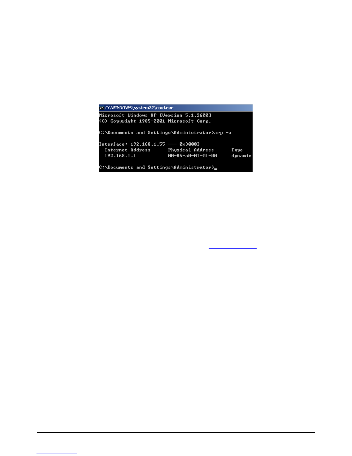
3.2 PREPARATIONS BEFORE ACCESSING THE ROUTER
Before accessing the GLB-802C ROUTER, make sure the communication between the PC and the
ROUTER are proper. Check the communication as follows:
1. Configure the IP address of the PC as 192.168.1.X (3~254), netmask as 255.255.255.0, gateway
address as 192.168.1.1(Ethernet connection) and gateway address as 192.168.1.2 (USB connection)
2. Use “arp -a” under DOS to check if the PC has learnt the MAC address of the ROUTER.
3.Ping the management IP address (192.168.1.1, when connected to the Ethernet port & 192.168.1.2,
when connected to the USB port) of the ROUTER. If the ping and the arp response is successful , it
indicates the connection between the router and the PC is proper.
3.3 WEB CONFIGURATION INTERFACE
When connected to the Ethernet port, open a web-browser enter http://192.168.1.1 (Router ’s IP address)
in the address bar to access the Web GUI.
Enter the user name and password
Default setting:
IP address: 192.168.1.1
User name: admin
Password: admin
When connected to the USB port, open a web-browser enter http://192.168.1.2 (Router’s IP address) in
the address bar to access the Web GUI.
Enter the user name and password
Default setting:
IP address: 192.168.1.2
User name: admin
Password: admin
Page 12

CHAPTER-3
D-Link GLB-802C ADSL2+ Router User Manual 9
3.3.1 HOME PAGE
With successful login, the Home page will be displayed as given below. This displays the current status
and the default configuration of the system.
3.3.2 QUICK CONFIGURATION
Select WAN protocol and related parameters as provided by Internet Service Provider
The common protocols:
z Dynamic IP Address
z Static IP Address
z PPP over Ethernet (PPPoE) & PPP over ATM (PPPoA)
z Bridge Mode
Page 13

CHAPTER-3
D-Link GLB-802C ADSL2+ Router User Manual 10
Predefined connection for major ISPs with their VPI and VCI values are available in the device.
IMPORTANT NOTE: Kindly reconfirm the values of VPI/VCI with the Internet Service Providers.
Connection name VPI VCI
MTNL 0 32
BSNL 0 35
Airtel 1 32
VSNL 0 33
3.3.2.1 To set the router in BRIDGE mode {Ethernet over ATM (RFC 1483 Bridge)}, go to Quick
configuration,
• Select the appropriate Connection name.
• “Enabled” in Operation mode,
• Connection type as “Bridge mode”
• “RFC1483 Bridge IP LLC (or) RFC1483 Bridge IP VC-Mux” as Encapsulation, (as provided by
ISP)
• Enter the VPI and VCI as provided by ISP,
• And, click “Submit” to save the settings.
Page 14

CHAPTER-3
D-Link GLB-802C ADSL2+ Router User Manual 11
3.3.2.2 SAVE & REBOOT CONFIGURATION
• Go to “Admin”, Click on “Commit & Reboot” tab and,
• Click on Commit button to save the settings.
• Click on Reboot with Reboot mode as “Reboot” to restart the router.
Page 15

CHAPTER-3
D-Link GLB-802C ADSL2+ Router User Manual 12
3.3.2.3. To set the router in PPP over Ethernet (RFC2516) (PPPoE) mode, go to Quick configuration,
• Select the appropriate Connection name
• “Enabled” in Operation mode
• Connection type as “PPPoA/PPPoE”
• “PPPoE LLC (or) PPPoE VC-Mux” as Encapsulation
• Enter the VPI and VCI as provided by ISP
• Enter the IP address/mask/gateway, if provided by the ISP
• “Enable” the default route
• Enter the “Username” and “Password”
• Enable the “Use DNS” or enter the DNS server IP address provided by ISP
• And, click “Submit” to save the settings
• Save the settings and reboot the router ( Refer to 3.3.2.2)
• To check the WAN IP address obtained from ISP ,go to HOME tab >System View
Page 16

CHAPTER-3
D-Link GLB-802C ADSL2+ Router User Manual 13
3.3.2.4. To set the router in Static IP address (1483 Bridge) mode, go to Quick configuration,
• Select the appropriate Connection name.
• “Enabled” in Operation mode
• Connection type as “Static IP address”
• “RFC1483 Bridge IP LLC (or) RFC1483 Bridge IP VC-Mux” as Encapsulation, (as provided by
ISP)
• Enter the VPI and VCI as provided by ISP
• Enter the IP address, subnet mask, gateway IP address and DNS server entries
• Enable the option of “Default route”
• And, click “Submit” to save the settings
• Save the settings and reboot the router (Refer to 3.3.2.2)
Page 17

CHAPTER-3
D-Link GLB-802C ADSL2+ Router User Manual 14
3.3.2.5. To set the router in Dynamic IP address (1483 Bridge) mode, go to Quick configuration,
• Select the appropriate Connection name
• “Enabled” in Operation mode
• Connection type as “Dynamic IP address”
• “RFC1483 Bridge IP LLC (or) RFC1483 Bridge IP VC-Mux” as Encapsulation, (as provided by
ISP)
• Enter the VPI and VCI as provided by ISP,
• Enable the “Use DHCP” option
• Enable the “Default route” option.
• Enable the “Use DNS” option or enter the DNS servers provided by the ISP.
• And, click “Submit” to save the settings.
• Save the settings and reboot the router (Refer to 3.3.2.2)
• To check the WAN IP address obtained from ISP ,go to HOME tab >System View
Page 18

CHAPTER-3
D-Link GLB-802C ADSL2+ Router User Manual 15
3.3.3 LAN CONFIGURATION
This page displays the IP address and subnet mask details. of the router.The default IP address and subnet
mask of the router is suitable for most networks.
z Conf. LAN IP Address: The IP address, i.e. the management IP address of the Ethernet port of the
router . The default is 192.168.1.1.
z USB IP Address: The IP address, i.e. the management IP address of the USB port of the router. The
default is 192.168.1.2.
z Conf. LAN Network Mask: The subnet mask of the IP address. The default value is 255.255.255.0.
To change the LAN IP address of Ethernet, go to LAN, click on LAN Config, under “LAN configuration”,
enter the new IP address and click on “Submit”. To change the IP address of USB interface, enter the new
IP address under “USB configuration”.
On clicking on “Submit”, a warning as shown below would be received .Click on “Submit” to apply the
settings.
Page 19

CHAPTER-3
D-Link GLB-802C ADSL2+ Router User Manual 16
3.3.4 DHCP CONFIGURATION:
z To enable the DHCP server, go to LAN, DHCP mode, select “DHCP server” and click on
“Submit”.
z To specify the address pool, go to DHCP Server and specify the required address pool as shown
below.
Page 20

CHAPTER-3
D-Link GLB-802C ADSL2+ Router User Manual 17
3.3.5 WAN CONFIGURATION
3.3.5.1 DSL
The DSL Status page displays current information on the DSL line performance. The page refreshes
according to the setting in the Refresh Rate drop-down list, which is configurable.
In the DSL Status table, the Operational Status setting displays a red, orange, or green to indicate that the
DSL line is idle, starting up, or up-and-running, respectively. DELT is Dual Ended line testing, It enables
the measurement of line conditions at both ends and gives information about loop-specific data rate
capacities. Start “DELT “, select it from the drop-down menu and click “Start”..
“DSL Param” provides the Line parameter details (Line attenuation & SNR parameters)
Page 21

CHAPTER-3
D-Link GLB-802C ADSL2+ Router User Manual 18
Click “Stats”, the follow interface will pop up.
Page 22

CHAPTER-3
D-Link GLB-802C ADSL2+ Router User Manual 19
The DSL statistics page reports DSL line performance statistics relating to the last 15-minute interval, the
current day and the previous day.
At the bottom of the page, the Detailed Interval Statistic table displays links which displays detailed data
for each 15-minute interval in the past 24 hrs. For eg: Clicking on 1-4, data displays for the 16 intervals
(15-minutes each) that make up the previous 4 hours.
3.3.5.2 ADSL
Click “WAN”->“ADSL” to configure the ADSL mode of the interface below.
3.3.6 IP ROUTING
To add a route, click add and enter the destination network address, subnet mask, Next hop and select the
required interface.
Page 23

CHAPTER-3
D-Link GLB-802C ADSL2+ Router User Manual 20
3.3.7 SERVICES
3.3.7.1 PORT FORWARDING (VIRTUAL SERVER)
Port forwarding allows to direct incoming traffic from the WAN side to a specific IP address on the LAN
side. i.e. create a port forwarding rule to make a computer on the LAN, such as a Web or FTP server,
available to Internet users without having to obtain a public IP address for that computer. The computer’s
private IP address is translated to the public IP address in all incoming and outgoing data packets.
• Go to “NAT” option , select the “NAT Rule entry” option , click on “Add”
• Under “NAT Rule Entry” , select the Rule flavour as “Port forwarding”
Page 24

CHAPTER-3
D-Link GLB-802C ADSL2+ Router User Manual 21
• Enter a “Rule id “.The Rule ID determines the order in which rules are invoked (the lowest numbered
rule is invoked first, and so on). To define two or more rules that act on the same set of IP
addresses, be sure to assign the Rule ID so that the higher priority rules are invoked first. It is
recommended to specify rule IDs as multiples of 5 or 10 so that, in the future, Inserting a rule
between two existing rules is possible. When a data packet matches a rule, the data is acted upon
according to that rule and is not subjected to higher-numbered rules.
• From the IFName drop-down list, select the interface on the device to which this rule applies.
Typically, NAT rules are used for communication between the LAN and the Internet. Because the
device uses the WAN interface (which is ppp-0 or eoa-0) to connect the LAN to the ISP, it is the
usual IFName selection.
• In the Local Address From field and Local Address To fields, type the starting and ending IP
addresses, respectively, of the range of private address used on the network that is to be translated.
• In the Global Address From and Global Address To fields, type the public IP address assigned by
the ISP. In case of dynamic global address leave the global address field blank. (i.e. 0.0.0.0) .Enter
the appropriate port settings.
• Click Submit a page displays to confirm the change, click close to return to the NAT
Configuration page. The new rule should display in the NAT Rule Configuration table.
3.3.7 .2 RIP
RIP is an Internet protocol to share routing table information with other routing devices on the LAN,
at the ISP’s location, or on remote networks connected via the ADSL line.
Page 25

CHAPTER-3
D-Link GLB-802C ADSL2+ Router User Manual 22
3.3.7.3 IP FILTERING
The IP filter feature enables to create rules that control the forwarding of incoming and outgoing data
between the LAN and the Internet and within the LAN. It is possible to create IP filter rules to block
attempts by certain computers on the LAN to access certain types of data or Internet locations and also
block incoming access to computers on the LAN.
When an IP filter rule is defined and the feature is enabled, router examines data packets to determine
whether they meet criteria set forth in the rule. The criteria can include the network or internet protocol
the packet carries, the direction in which it is traveling (for example, from the LAN to the Internet or vice
versa), the IP address of the sending computer, the destination IP address, and other characteristics of the
packet data.
If the packet matches the criteria established in a rule, the packet can either be accepted (forwarded
towards its destination), or denied (discarded), depending on the action specified in the rule.
a. Configuring IP Filter Global Settings
The IP Filter Configuration page enables to configure the following global IP filter settings.
• Security Level: This setting determines which IP filter rules take effect, based on the security level
specified in each rule. For example, when High is selected, only those rules that are assigned a
security value of High will be in effect. The same is true for the Medium and Low settings. When
“None” is selected, IP filtering is disabled.
Page 26

CHAPTER-3
D-Link GLB-802C ADSL2+ Router User Manual 23
• Private/Public/DMZ Default Action: This setting specifies a default action to be taken (Accept or
Deny) on private, public interfaces when they receive packets that do not match any of the filtering
rules.
• A public interface typically connects to the Internet. PPP, EoA, and IPoA interfaces are typically
public. Packets received on a public interface are subject to the most restrictive set of firewall
protections defined in the software. Typically, the global setting for public interfaces is Deny, so
that all accesses to the LAN initiated from external computers are denied (discarded at the public
interface), except for those allowed by a specific IP filter rule.
• A private interface connects to the LAN, such as the Ethernet interface. Packets received on a
private interface are subject to a less restrictive set of protections, because they originate within
the network. Typically, the global setting for private interfaces is Accept, so that LAN computers
have access to the ADSL/Ethernet routers' Internet connection.
b. Creating IP Filter Rules
To create an IP filter rule, various criteria are set that must be met in order for the rule to be invoked.
Use these instructions to add a new IP filter rule.
• On the IP Filter Configuration page, click Add.
Page 27

CHAPTER-3
D-Link GLB-802C ADSL2+ Router User Manual 24
Enter or select data for each field that applies to the rule. The following table describes the fields:
Field Description
Rule ID
Each rule must be assigned a sequential ID
number. Rules are processed from lowest to
highest on each data packet, unti l a match i s
found. It is recommended to assign rule IDs in
multiples of 5 or 10 (e.g., 10, 20, 30) so that
enough room is left between them for inserting
new rules if necessary.
Action
The action that will be taken when a packet
matches the rule criteria. The action can be Accept
(forward to destination) or Deny (discard the
packet).
Direction
Specifies whether the rule should apply to data
packets that are incoming or outgoing on the
selected interface.
Incoming refers to packets coming from the LAN,
and outgoing refers to packets going to the
Internet.
Interface
The interface on the router on which the rule will
take effect.
In Interface
The interface from which packets must have been
forwarded to the interface specified in the
previous selection. This option is va lid o nly for
the outgoing direction.
Log Option
When Enabled is selected, a log entry will be
created on the system each time this rule is
invoked. The log entry will incl ude the time of the
violation, the source address of the computer
responsible for the violation, t he destinati on IP
address, the protocol being used, the source and
destination ports, and the number viola tions
occurring in the previous x minutes.
Security Level
The security level that must be ena bled globa lly
for this rule to take affect. A rule will be active
only if its security level is the same as the globally
configured setting. For example, if the rule is set
to Medium and the global firewall level is set to
Medium, then the rule will be active; but if the
global firewall level is set to High or Low, the n
the rule will be inactive.
Black List Status
Specifies whether or not a violatio n of t his rule
will result in the offending computer's IP
address being added to the blacklist, which blocks
the router from forwarding packets from that
source for a specified period of time.
Log Tag
A description of up to 16 characters to be
recorded in the log in the event that a packet
violates this rule. Be sure to set the Log O ption to
Enable when a Log Tag is configured.
Page 28

CHAPTER-3
D-Link GLB-802C ADSL2+ Router User Manual 25
Field Description
Start/End Time
The time range during which this rule is to be in
effect, specified in military units.
Src IP Address/Dest IP Address
IP address criteria for the source computer(s)
(from which the packet originates) and the
destination computer. In the drop-down list, it is
possible to configure the rule to be invoked on
packets containing:
any: any source IP address.
lt: any source IP address that is numerically less
than the specified address.
lteq: any source IP address that is numerically
less than or equal to the specified address.
gt: any source IP address that is numerically
greater than the specified address.
eq: any source IP address that is numerically
equal to the specified address.
neq: any source IP address that is not equal to the
specified address.
range: any source IP address that is within the
specified range, including its endpoints.
out of range: any source IP address that is outside
the specified range.
self: the IP address of the ADSL/Ethernet router
interface on which this rule takes effect.
bcast: (destination address only) Specifies that
the rule will be invoked for any packets sent to the
broadcast address for the receiving interface. (The
broadcast address is used to send packets to all
hosts on the LAN or subnet connected to the
specified interface.) When this option is selected,
address need not be specified, so the address
fields are dimmed.
Protocol
The basic IP protocol criteria that must be met for
rule to be invoked. Using the options in the
drop-down list, specify that packe ts must contain
the selected protocol (eq), that they must not
contain the specified protocol (neq), or that the
rule can be invoked regardless of the protocol
(any). TCP, UDP, and ICMP are comm on IP
protocols; others can be identified b y num ber
from 0-255, as defined by the Internet Assigned
Numbers Authority (IANA).
Apply Stateful Inspection
When this option is enabled, packets are
monitored for their state (i.e., whether a packet is
the initiating packet or a subsequent packet in an
ongoing communication, etc). This opti on
provides a degree of security by
blocking/dropping packets that are not received in
the anticipated state. Such packets can signify an
unwelcome attempt to gain access to a network.
Page 29

CHAPTER-3
D-Link GLB-802C ADSL2+ Router User Manual 26
Field Description
Source/Destination Port
Port number criteria for the source computer(s)
(from which the packet originates) and
destination computer(s).
Port numbers identify the type of traffic that the
computer or server can handle and are specified
by the Internet Assigned Numbers Authority
(IANA). For example, port number 80 indicates a
Web server, 21 indicates an FTP server.
TOD Rule Status
The Time of Day Rule Status determines how the
Start Time/End Time settings are used.
o Enable: (Default) The rule is in effect for the
specified time period.
o Disable: The rule is not in effect for the
specified time period, but is effective at all
other times.
When the required criteria is selected, ensure that the Enable radio button is selected at the top of the page,
and then click “Submit”. After a confirmation page displays, the IP Filter Configuration page will redisplay
with the new rule showing in the table.
If the security level of the rule matches the globally configured setting, a green indicator displays in the
Status column for that rule, indicating that the rule is now in effect. A red indicator displays when the rule is
disabled or if its security level is different from the globally configured level.
Ensure that the Security Level and Private/Public/DMZ Default Action settings on the IP Filter
Configuration page are configured as needed, then click submit. A page displays to confirm the changes.
Example
Blocking a specific computer on the LAN from accessing Web servers on the Internet:
• Add a new rule for outgoing packets on the ppp-0 interface from any incoming interface (this would
include the eth-0 and usb-0 interfaces).
• Specify the source IP address of the computer to be blocked.
• Specify the Protocol as TCP and enable the Store State setting.
• Specify the destination port as 80, which is the well-known port number for web servers.
• Enable the rule by clicking the radio button at the top of the page.
• Click submit to create the rule.
• On the IP Filter Configuration page, set the Security Level to the same level which is chosen for the
rule, and set both the Private Default Action and the Public Default Action to Accept.
• Click submit.
With this configuration, the specified computer will not be able to access the Web, but will be able to access
FTP Internet sites (and any others that use destination port numbers other than 80).
Page 30

CHAPTER-3
D-Link GLB-802C ADSL2+ Router User Manual 27
3.3.7.4 DNS
DNS servers map the user-friendly domain names that users type into their Web browsers (e.g.,
"yahoo.com") to the equivalent numerical IP addresses that are used for Internet routing.
Configuring DNS Relay
When the device's LAN interface IP address is specified as the DNS address, then the ADSL/Ethernet
automatically performs DNS relay; i.e., because the device itself is not a DNS server, it forwards domain
name lookup requests that it receives from LAN computers to a DNS server at the ISP. It then relays the
DNS server's response to the PC.
3.3.7.5 DDNS
Dynamic DNS (DDNS) is a service that facilitates outside Internet access to a LAN host even when the
host's dynamically-assigned IP address changes frequently.
a. Add the DDNS host address registered with the DDNS provider (For eg: test.dynalias.org)
a. Select the interface (Interface connected to the Internet i.e. ppp-0), select the DDNS
provider under “Service name “.
b. Enter the username and password for the DDNS account.
c. Click on “Submit”.
Page 31

CHAPTER-3
D-Link GLB-802C ADSL2+ Router User Manual 28
3.3.7.6 UPNP
UPNP: Universal Plug and Play.
UPnP boasts device-driver independence and zero-configuration networking.
Page 32

CHAPTER-3
D-Link GLB-802C ADSL2+ Router User Manual 29
3.3.7.7 SNTP
Simple Network Time Protocol (SNTP) is a simplified adaptation of the Network Time Protocol (NTP)
that is used to synchronize computer clocks on the Internet.
• Add the SNTP IP address or Domain name
• Enable the SNTP feature.
• Click on Submit.
To check the time settings go to the “Home->system view” web page
3.3.8 Admin
3.3.8.1 User Config
The Router is configured with a default user name and password or login, for accessing Web
Configuration. The default username: admin and password: admin.
To add a new user click on “add “and enter the details.
3.3.8.2 Commit & Reboot
Use this page to commit changes to system memory and reboot
.
Page 33

CHAPTER-3
D-Link GLB-802C ADSL2+ Router User Manual 30
• Click on Commit button to save the settings.
• Click on Reboot with Reboot mode as “Reboot” to restart the router.
• Reboot from Default Configuration reboots the device to factory default settings
3.3.8.3 Local Image Upgrade
Click “Admin>Local Image Upgrade” to show the following page, it allows to upgrade the image. In the
Upgrade File text-box, type the following path and file name of the file or click on Browse and specify
the path and click on Upload. When loading is complete, a message indicating the same is displayed. For
the new image to take effect, reboot the router
When loading is complete, reboot the device for the new image to take effect.
3.3.8.4 Diagnostics
The diagnostics page allows to run a series of diagnostic tests of the system software and hardware
connections. Ping and Traceroute utilities are also available to troubleshoot connection problems.
.
Page 34

CHAPTER-3
D-Link GLB-802C ADSL2+ Router User Manual 31
3.3.8.5 Port settings
1. Click the Admin tab, and click on Port settings.
2. Type the new port numbers in the appropriate text boxes and click Submit. (Range: 61000-62000).
3. Click Commit & Reboot and click Commit to save changes to permanent memory. Click Reboot.
Note: The new settings will be effective after you rebooting the router.
Page 35

CHAPTER-3
D-Link GLB-802C ADSL2+ Router User Manual 32
3.3.8.5 Management Control
The Router can be accessed remotely by enabling the services under WAN access. To provide access of
the router to a particular host, enter its IP address under the IP address tab.
3.3.8.6 System Alarms
Alarms, also called traps, are caused by a variety of system events, including connection attempts, resets,
and configuration changes. This information may be helpful in working with the ISP to troubleshoot
issues, if any (Despite their name, not all alarms indicate problems in the functioning of the system.)To
display the Alarm page, click the Admin tab, and then click “Alarm” in the task bar.
.
Each row in the table displays the time and date that an alarm occurred, the type of alarm, and a brief
statement indicating its cause. Click on the Refresh Rate drop-down list to select a recurring time interval
after which the page will redisplay with new data.
Click “Save Alarm” to display a Windows File Download dialog box that enables opening or saving the
contents of the log to the PC. The file is assigned the default name alarm.vlf, and can be viewed with any
text editor.
To remove all entries from the list, click “Clear “. New entries will begin accumulating and will display
when “Refresh” is clicked.
Page 36

CHAPTER-3
D-Link GLB-802C ADSL2+ Router User Manual 33
3.3.8.7 System Log
System Log displays data generated or acquired by routine system communication with other devices,
such as the results of negotiations with the ISP’s computers for DNS and gateway IP addresses. This
information does not necessarily represent unexpected or improper functioning and is not captured by the
system traps that create alarms. This information accumulates and displays in a system log window.
To view the system log, click the Admin tab, and then click “system log” in the task bar.
Click “Save Log” to display a Windows File Download dialog box that enables opening or saving the
contents of the log to the PC. The file is assigned the default name syslog.vlf, and can be viewed with any
text editor.
3.3.8.9 Backup/Restore Config
To backup and restore the configuration from local machine, follow the steps given below
1. Make sure that the changes made in the current session have been saved (Admin->Commit and
reboot-> commit)
Page 37

CHAPTER-3
D-Link GLB-802C ADSL2+ Router User Manual 34
2. In the Admin tab, click Backup/Restore config.
3. To take a backup of the configuration, click Save config .A Windows dialog box will display to choose
where to save the file.
4. To restore a saved configuration, select the saved file and click Upload.
3.3.8.10 SNMP
To create Communities
1. On the SNMP configuration page, type a community name in the left column of the table.
2. From the Access column of the table, select the privileges (Read only or Read/Write) to assign to all
hosts that are part of this community.
4. Click “Add comm”
Page 38

CHAPTER-3
D-Link GLB-802C ADSL2+ Router User Manual 35
To add hosts to Communities
1. Click “Add Host”
2. Enter the IP address of the host computer and click Submit.
The newly added hosts have access to the MIB with the privilege level associated with the community.
To view all hosts and the communities they are assigned, click “View hosts” on the main SNMP
configuration page. To view statistics relating to SNMP packets, click “Global Stats” on the main SNMP
configuration page.
Notes: SNMP protocol version just supports SNMPv1.
Page 39

WARRANTY INFORMATION
For detailed Warranty information, please refer to “http://www.dlink.co.in/support/Warranty.aspx”
Only Registered Customer will avail the Life Time Warranty offer. For Product Registration
please log onto D-Link website www.dlink.co.in Or Please contact D-Link Technical Assistance
Centre. MTNL/BSNL Callers use Toll Free no# 1800 22 2002. Mobile and others shall contact #
022-2844 7600.
Digi-Care Life Time Warranty also covers internal power supply and fans.
External Adapter shall carry only one year warranty. This offer does not cover add on upgrades,
modules and others Accessories like Cables, Brackets and Stands.
D-Link has all right to change the models covered under the Digi-Care program. D-Link shall
announce new models to be covered under Digi-care Program as and when required. The said
program at present applies only to the above referred selected products for limited duration.
Digi-Care is D-Link India’s Premium Service Program. Please refer to our website for details of
Digi-Care Program.
Procedure: The customer shall contact D-Link Technical Assistance Centre and must obtain Case ID.
MTNL/BSNL Callers shall use Toll Free No# 1800 22 2002. For Mobile and others shall use # 0222844 7600. D-Link Technical Assistance Centre will attempt to assist the customer in resolving any
suspected defects in the product. If the product is considered defective, the customer shall to return
the defective Product to nearest D-Link Service Centre or D-Link Collection Center. For all locations
where D-Link Service Centre is not present, the local Distributor or Reseller is responsible to
collect the Products and represent as a D-Link Collection Centre. In case of Dead on Arrival
(DOA) customers are requested to contact Point of Purchase for Replacement. Local Distributor is
responsible replace or refund for DOA Valid Cases. For Warranty Repairs Customers are
requested to send the description note of the Hardware defect or Software nonconformance to allow
D-Link to confirm the same.
Please Ref. D-Link website: www.dlink.co.in Support Process and Service Centre Contact details
This Digi-Care Life Time Warranty is issued subject to the terms and conditions set forth herein.
Subject to the same, D-Link provides this Limited Hardware warranty only to the person or entity that
originally purchased the product from D-Link India or its authorized reseller or distributor provided
the same are purchased and delivered within Republic of India.
Warranty:
D-Link warrants that the hardware portion of the D-Link product described in this warranty ("Hardware")
will be free from material defects in workmanship and materials under normal use during
Warranty period set forth below ("Warranty Period"), except as otherwise stated herein.
Hardware Warranty:
Hardware warranty period shall be limited to three years. The customer's sole and exclusive remedy
and the entire liability of D-Link and its suppliers under this Limited Warranty will be, at D-Link's
option, to repair or replace the defective Hardware during the Warranty Period at no charge to the original
owner. Any repair or replacement will be rendered by D-Link at D-Link Service Centre. The
replacement hardware need not be new or have an identical make, model or part. D-Link may, at its
option, replace the defective Hardware or any part thereof with any reconditioned product that D-Link
reasonably determines is substantially equivalent (or superior) in all material respects to the defective
hardware. Repaired or replacement hardware will be warranted for the remainder of the original Warranty
Period. If a material defect is incapable of correction, or if D-Link determines that it is not practical to
repair or replace the defective Hardware, the actual price billed by D-Link less usage charge will be
refunded. All Hardware or parts thereof replaced by D-Link and the products for which the purchase
price is refunded, shall become the property of D-Link upon replacement or refund.
Page 40

Software Warranty:
D-Link issues this Limited Software Warranty that the software portion of the product ("Software")
will substantially conform to D-Link's then current functional specifications for the software, as set forth
in the applicable documentation, from the date of original retail purchase of the Software for a period of
ninety (90) days ("Software Warranty Period"), provided that the Software is properly installed on
approved hardware and operated as contemplated in its documentation. D-Link further warrants that,
during the Software Warranty Period, the magnetic media on which D- Link delivers the Software will be
free of physical defects. The customer's sole and exclusive remedy and the entire liability of D-Link and
its suppliers under this Limited Warranty will be, at D-Link's option, to replace the non-conforming
Software (or defective media) with software that substantially conforms to D-Link's functional
specifications for the Software or to refund the portion of the actual purchase price paid that is
attributable to the Software. Except as otherwise agreed by D-Link in writing, the replacement Software
is provided only to the original licensee, and is subject to the terms and conditions of the license granted
by D-Link for the Software. Replacement Software will be warranted for the remainder of the original
Warranty Period and is subject to the same limitations and exclusions. If a material non-conformance is
incapable of correction, or if D-Link determines in its sole discretion that it is not practical to replace the
non-conforming Software, the price paid by the original licensee for the non Conforming Software will
be refunded by D-Link provided that the non-conforming Software (and all copies thereof) is first
returned to D-Link. The license granted respecting any Software for which a refund is given
automatically terminates.
Disclaimer of Other Warranties:
EXCEPT FOR THE LIMITED WARRANTY SPECIFIED HEREIN, THE PRODUCT IS PROVIDED
"AS-IS"WITHOUT ANY WARRANTY OF ANY KIND WHATSOEVER INCLUDING, WITHOUT
LIMITATION, ANY WARRANTY OF MERCHANTABILIT Y, FIT NE SS FOR A PA RTICUL AR
PURPOSE AND NON-INFRINGEMENT. IF ANY IMPLIED WARRANTY CAN NOT BE
DISCLAIMED IN ANY TERRITORY WHERE A PRODUCT IS SOLD, THE DURATION OF SUCH
IMPLIED WARRANTY SHALL BE LIMITED TO NINETY (90) DAYS. EXCEPT AS EXPRESSLY
COVERED UNDER THE LIMITED WARRANTY PROVIDED HEREIN, THE ENT I RE RISK AS TO
THE QUALITY, SELECTION AND PERFORMANCE OF THE PRODUCT IS WITH THE
PURCHASER OF THE PRODUCT.
Limitation of Liability: TO THE MAXIMUM EXTENT PERMITTED BY LAW, D-LINK IS NOT
LIABLE UNDER ANY CONTRACT, NEGLIGENCE, STRICT LIABILITY OR OTHER LEGAL OR
EQUITABLE THEORY FOR ANY LOSS OF USE OF THE PRODUCT, INCONVENIENCE OR
DAMAGES OF ANY CHARACTER, WHETHER DIRECT, SPECIAL, INCIDENTAL OR
CONSEQUENTIAL (INCLUDING, BUT NOT LIMITED TO, DAMAGES FOR LOSS OF
GOODWILL, LOSS OF REVENUE OR PROFIT, WORK STOPPAGE, COMPUTER FAILURE OR
MALFUNCTION, FAILURE OF OTHER EQUIPMENT OR COMPUTER PROGRAMS TO WHICH
D-LINK'S PRODUCT IS CONNECTED WITH, LOSS OF INFORM A T IO N OR DA TA
CONTAINED IN, STORED ON, OR INTEGRATED WITH ANY PRODUCT RETURNED TO DLINK
FOR WARRANTY SERVICE) RESULTING FROM THE USE OF THE PRODUCT,
RELATING TO WARRANTY SERVICE, OR ARISING OUT OF ANY BREACH OF THIS LIMITED
WARRANTY, EVEN IF D-LINK HAS BEEN ADVISED OF THE POSSIBILITY OF SUCH
DAMAGES. THE SOLE REMEDY FOR A BREACH OF THE FOREGOING LIMITED WARRANTY
IS REPAIR, REPLACEMENT OR REFUND OF THE DEFECTIVE OR NON-CONFORMING
PRODUCT.THE MAXIMUM LIABILITY OF D-LINK UNDER THIS WARRANTY IS LIMITED TO
THE PURCHASE PRICE OF THE PRODUCT COVERED BY THE WARRANTY. THE
FOREGOING EXPRESS WRITTEN WARRANTIES AND REMEDIES ARE EXCLUSIVE AND ARE
IN LIEU OF ANY OTHER WARRANTIES OR REMEDIES, EXPRESS, IMPLIED OR STATUTORY.
Governing Law: This Limited Warranty shall be governed by Indian laws.
Copyright Statement: No part of this publication or documentation accompanying this product
may be reproduced in any form or by any means or used to make any derivative such as
translation, transformation, or adaptation without permission from D-Link Limited as
Stipulated by the copyright enactments in India and any amendments thereto. Contents are
subject to change without prior notice. All rights reserved.
 Loading...