

Page 1
Building Networks for People
D-Link Video Server
DVS-301
User Manual
DVS-301 User Manual v1.00
ver.1.00
20040507
Page 2

Building Networks for People
Before You Use
Law in your country may prohi bit surveillance devices. Though Video Server is not only a
high performance surveillance system but also a networked video server, ensure that the
operation of such devices are legal before installing this unit for surveillance.
It is important to carefully check the contents with the "Package Contents" section after
opening the package. Understanding the physical description can prevent damage caused
by abnormal usage and reduce mo st problems during installation.
Basically Video Server is a network device and should be easy to use for those who a lready
have basic network knowledge. If there is a system error and it does not recover easily d ue
to erroneous configuration, check the section "Auxiliary buttons" to restore factory default
settings and run installation again.
Video Server has been designed for various environments and can be used t o build var ious
applications for general security or demonstration p urpose s. For standard applications, read
"System configuration" to understand all functions. To make the best usage of Video Server,
review "Advanced functions" to get creative ideas. To those professional developers, "URL
Commands of Video Server" will be a very helpful reference.
Those paragraphs preceding by
should be fully understood and cautioned. Ignoring the
warnings may result in serious hazards.
DVS-301 User Manual v1.00
1
Page 3

Building Networks for People
Table of Contents
Before You Use .......................................................................... 1
Table of Contents....................................................................... 2
Package Contents...................................................................... 4
Physical Description......................... .. ... ..... ... ... .. ... ..... ... ... .. ... ... . 1
Front Panel..............................................................................................1
Rear Panel ..............................................................................................2
How to Install ............................................ ................................. 5
Ethernet Environment ................................................... ............ 6
Hardware installation...............................................................................6
Software configuration.............................................................................8
First access to Video Server..................................................................14
Modem Environment ............................................................... 16
Hardware installation.............................................................................16
Software configuration...........................................................................18
First access to Video Server..................................................................26
How to Use............................................................................... 28
Authentication........................................................................................ 29
Primary user’s capability .......................................................................31
Client Setting.........................................................................................32
System configuration.............................................................................34
Advanced functions...............................................................................64
URL commands of Video Server...........................................................69
Appendix .................................................................................. 80
A. POST procedure...............................................................................80
B. Frequently asked questions..............................................................81
DVS-301 User Manual v1.00
2
Page 4

Building Networks for People
C. Technical specifications ....................................................................84
DVS-301 User Manual v1.00
3
Page 5

Building Networks for People
Package Contents
DVS-301 User Manual v1.00
4
Page 6
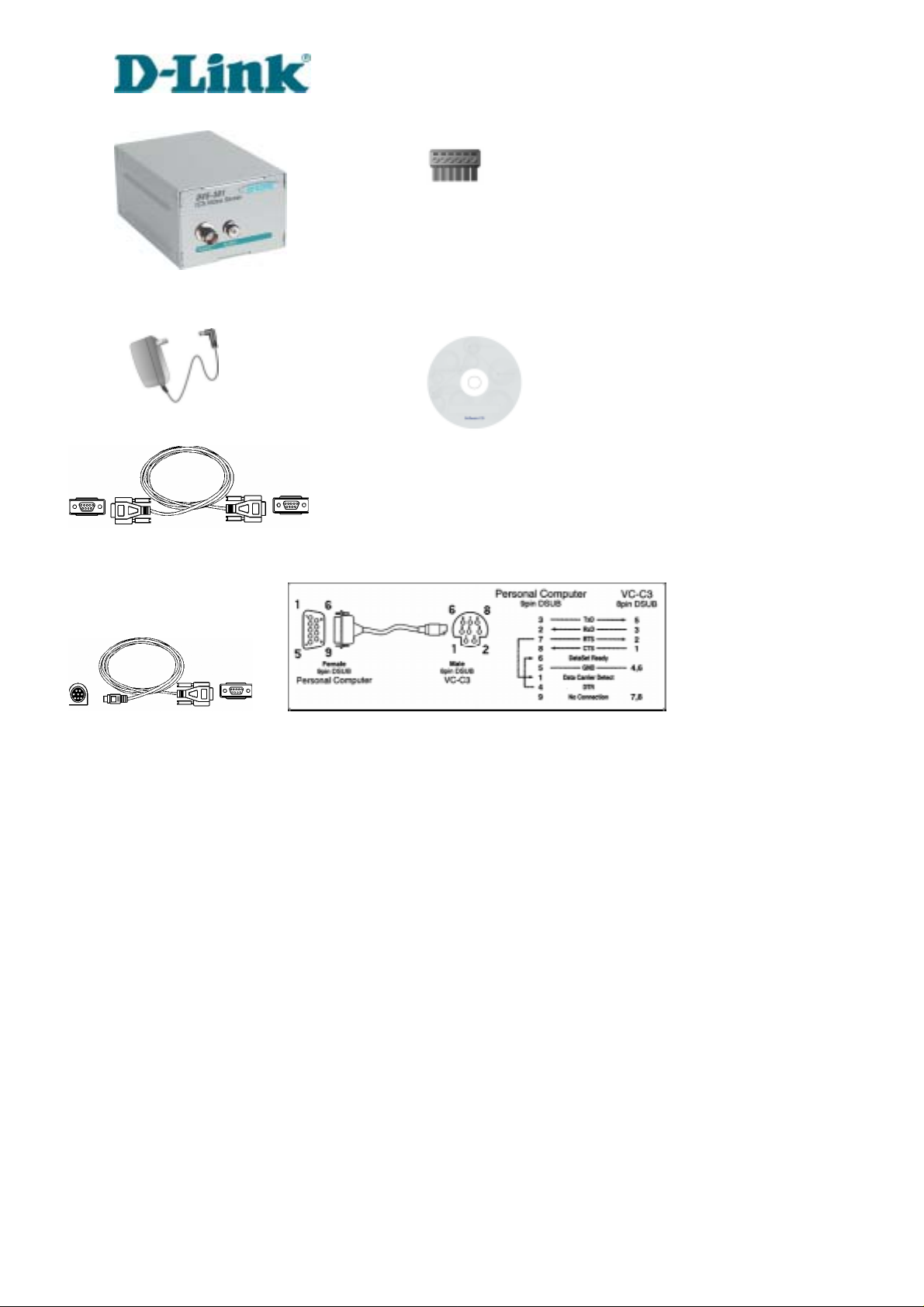
Video Server DVS-301
Power adapter
Null modem cable
Camera control cable
Building Networks for People
I/O terminal block connector
Software CD
DVS-301 User Manual v1.00
Page 7
Building Networks for People
Physical Description
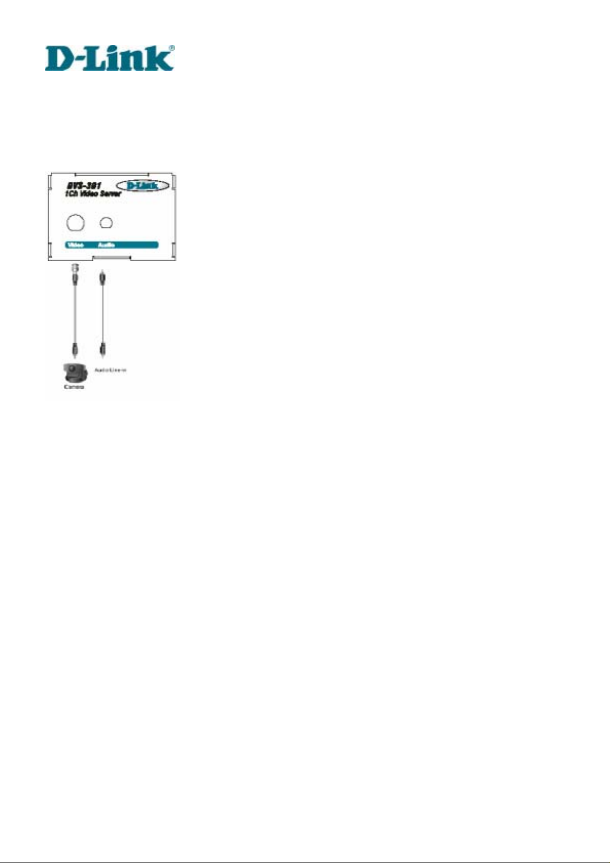
Front Panel
BNC video input
75Ohms resistance video port for connecting an external camera. To ensure video modulation
type being correctly detected, cameras should be attached and powered on before the Video
Server is powered on.
RCA audio input
The audio input is connected by RCA connector of mono-audio Line-In signal.
DVS-301 User Manual v1.00
1
Page 8
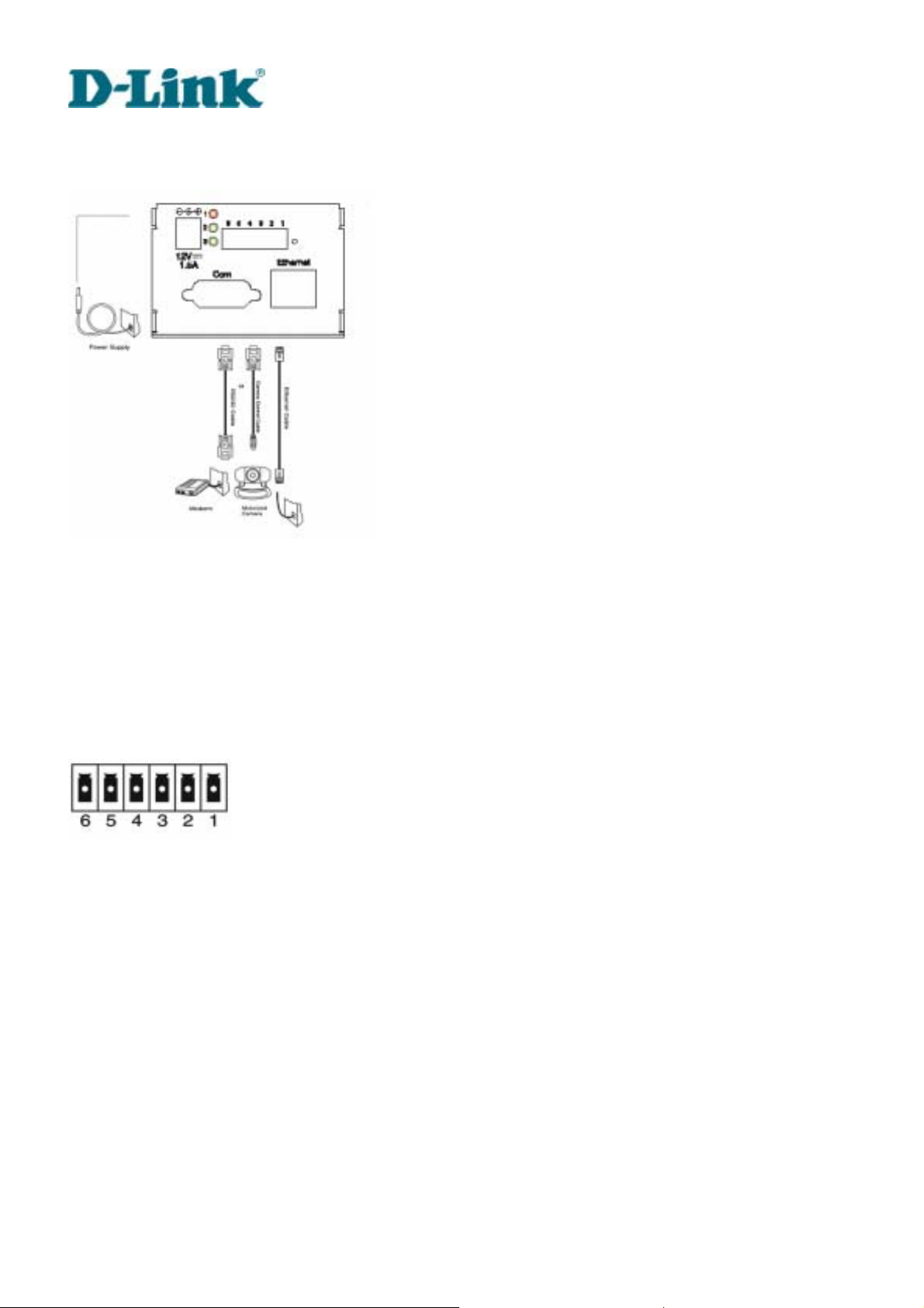
Rear Panel
Building Networks for People
Ethernet 10/100 socket
Connect to Ethernet network with a UTP category 5 cable that cannot exceed 100 meters. Once
the Ethernet cable is connected without error, Video Server will utilize Ethernet interface
regardless of modem connection.
COM port
This RS232 serial port can connect with a modem or included null modem cable to utilize
dial-up network when Ethernet is not available. If Video Server operates with Ethernet interface,
administrators may use this port to control PTZ camera attached to VIDEO.
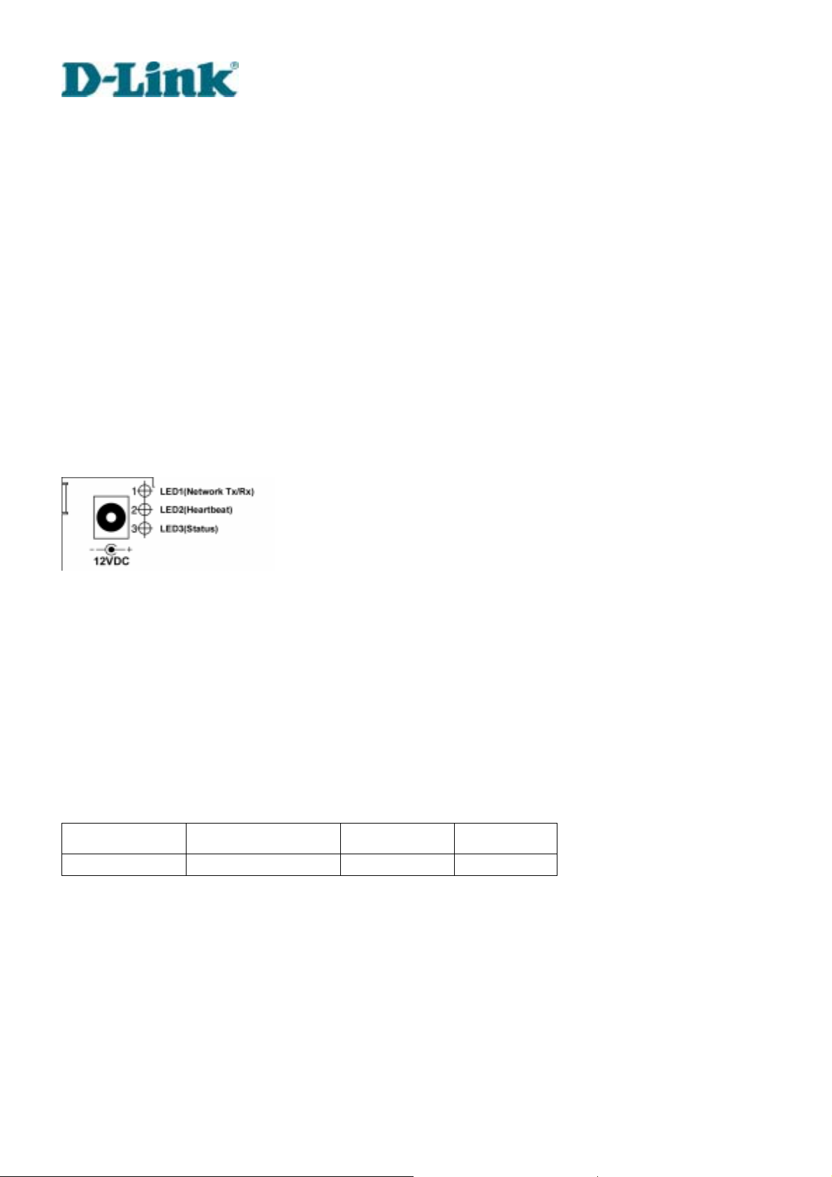
General I/O terminal block
1 Å DI+ INPUT (Max. 50mA, 12VDC)
2 Å DI- INPUT
3 Å SW_COMMON OUTPUT (short with NC at initial state)
4 Å SW_NOPEN OUTPUT (Max. 1A, 24VDC or 0.5A, 125VAC)
5 Å RS485 B (inverting)
6 Å RS485 A (non-inverting)
DVS-301 User Manual v1.00
2
Page 9
Building Networks for People
Video Server provides a very flexible general I/O interface to combine with the user’s security
devices such as sensors, alarms, lighting or door locks. The general I/O terminal block has six
pins for device control. These pins can be divided into two categories based on their functions,
including RS485 and digital inputs and outputs.
If the device connected to COM has an RS485 interface, wire two control lines to pin 5 and pin 6.
After switching to RS485 on the configuration page, the PTZ control commands will be directed
through pin 5 and pin 6. If the distance from the controlled device is too far to allow accurate
function, an external power source may be used to pull high the RS485 signal.
Video Server provides one digital input and one relay switch. Pin 1 and pin 2 can be connected
to external sensor and the state of voltage will be monitored according to the programmed
scripts in configuration. The relay switch can be used to turn on or off external devices.
Status LEDs
Each time Video Server starts, it will perform a Power-On Self Test, abbreviated as POST
hereafter, to examine every hardware module. As soon as the administrator plugs in the power
adapter, both LEDs under the network LED will flash one by one until the POST is done. If any
module fails, both LEDs will indicate to the users the error according to the pattern listed in
Appendix A. If the result is good, both LEDs will turn off for a while and then follows the pattern
below. Network interface depends on the peripherals including Ethernet UTP cable, modem or
null modem cable. If the Ethernet cable between Video Server and Ethernet hub is good, Video
Server will choose the Ethernet network. If Ethernet is unavailable but a operational modem is
connected, the network interface will be PPP with modem. If either of the above is not the case,
Video Server will try the interface of PPP with null modem.
Network Interface Condition LED2 (Heartbeat) LED3 (Status)
Ethernet before installed OFF OFF
DVS-301 User Manual v1.00
3
Page 10
Building Networks for People
after installed flash OFF
during camera control flash Flash
PPP with modem after POST flash ON
before connected ON ON PPP with null
modem
after connected flash ON
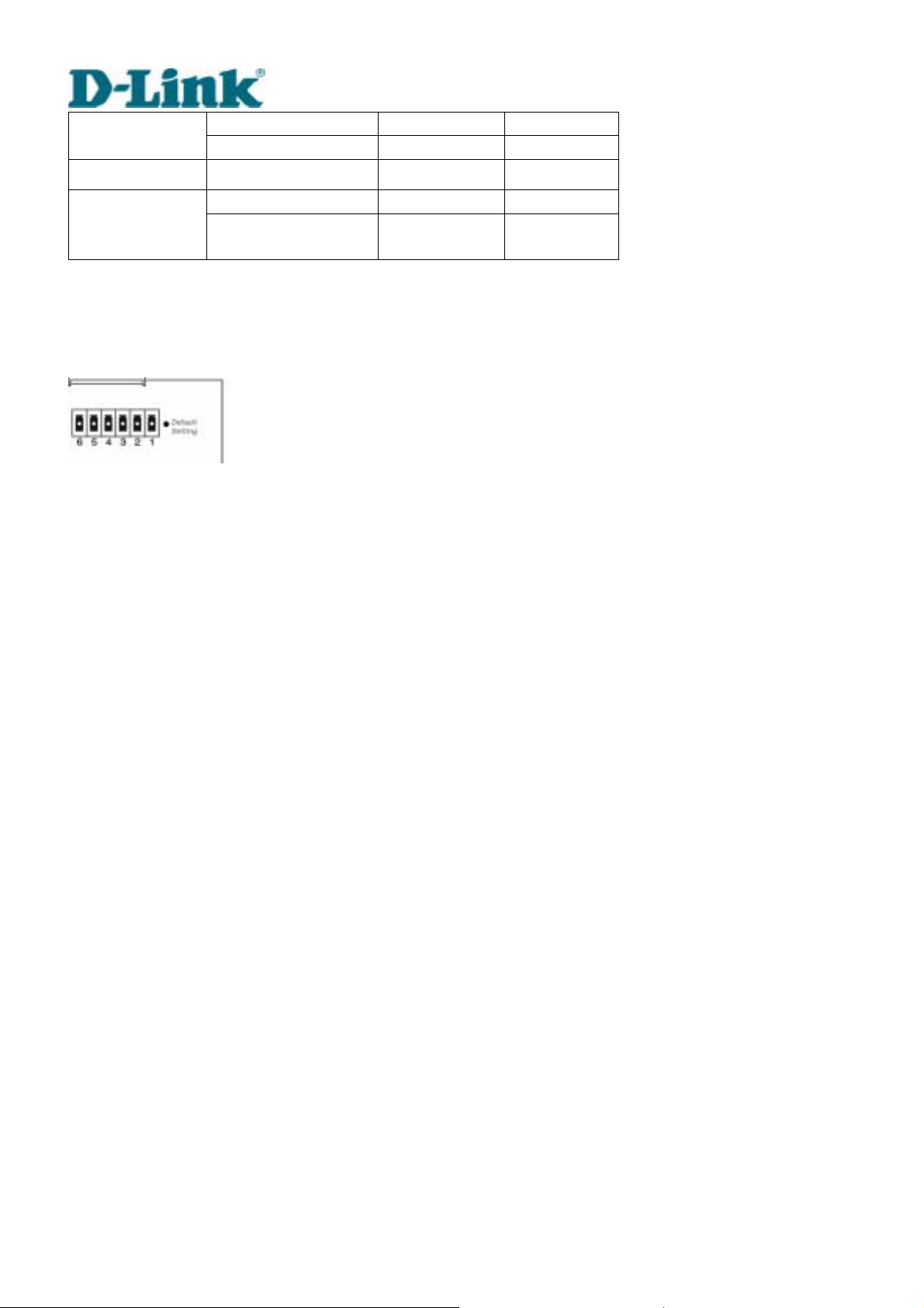
Restore button
There is a button hidden in the box for restoring the system factory default setting s. When the
system fails to install or operates abnormally, use the included assistant stick in the package
and follow the following procedures to reset the system back to its original status.
Poke the assistant stick into the hole to press down on the restore button. Restart the system by
unplugging and re-plugging the power jack. While keeping the button pressed, the system will
perform POST twice rather than the usual once, which can be observed from the flashing LEDs.
After the system flashes the LEDs for the second time, withdraw the stick to release the button.
The system will have restored factory default settings at that moment.
Power adapter
Connect the power jack of the included power adapter. Connecting the power adapter should
be the last operation while physically installing Video Server.
DVS-301 User Manual v1.00
4
Page 11

Building Networks for People
How to Install
To easily fit into various environments, Video Server automatically detects the attached
interfaces and configures itself to the best condition. Therefore users need not care whether the
connected cameras are either NTSC or PAL, how to select the network between Ethernet and
modem, and whether the Ethernet speed is 10Mbps or 100 Mbps. If the connected motorized
camera is on the support list, users only need to plug and play without complicated
configurations.
Video Server supports Ethernet and modem interfaces according to the user's existing network.
Ethernet can provide higher bandwidth to achieve the best performance while dial-up network
with modem is more common in current Internet applications. Refer to the related installation
section for your network environment. If both interfaces are available, Ethernet is recommended
and will be chosen as the first priority if Ethernet cable and modem are concurrently attached.
Managing to install in the other interface will automatically clear the previous network settings to
start new installation.
In the following content, "user" refers to those who can access Video Server and "administrator"
refers to the supervisor who has the root password to configure Video Server in addition to
general access. Administrators should carefully read this manual, especially during installation.
DVS-301 User Manual v1.00
5
Page 12
Building Networks for People
Ethernet Environment
Hardware installation
Before installing multiple Video Servers at the well-chosen locations, the administrator should
memorize the serial numbers on the packages respectively for future use.
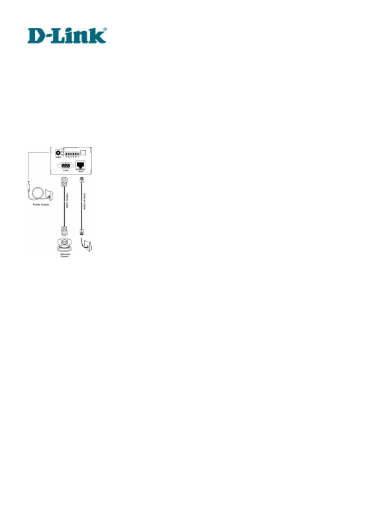
Cable connection
Shut down all the peripheral devices prior to connection. Connect the supplied cables from
Video Server to related devices according to the following steps. Note that the power adaptor
must be kept unplugged until other cables are firmly connected.
DVS-301 User Manual v1.00
6
Page 13

Building Networks for People
Power on
Make sure all cables are correctly and firmly connected before turning on Video Server. Turn on
cameras, sensors, alarm devices, and then attach the power adaptor of Video Server to the
electric power socket*. After the POST (power-on self test) is complete and the result is
successful, Video Server is ready for software configuration as described in this manual. At this
stage, network speed and video modulation type are automatically detected. If the detection of
video modulation fails, administrators may change the setting on the configuration page. Refer
to the configuration section for further information.
Connect the power jack of th e power adapter to Video Server prior to plugging the utility
end into the utility power socket. It will reduce accidental electric surge shock.
DVS-301 User Manual v1.00
7
Page 14
Building Networks for People
Software configuration
Easy way with installer program
In order to configure Video Servers remotely, administrators should keep the MAC address of
the new Video Servers for identification and initial passwords. After successfully mounting
Video Servers in the proper position, run the Installer program on the appropriate PC to locate
the newly installed Video Servers. Video Servers also support manual setup procedures to
non-Windows based environments. The manual procedure is described next.
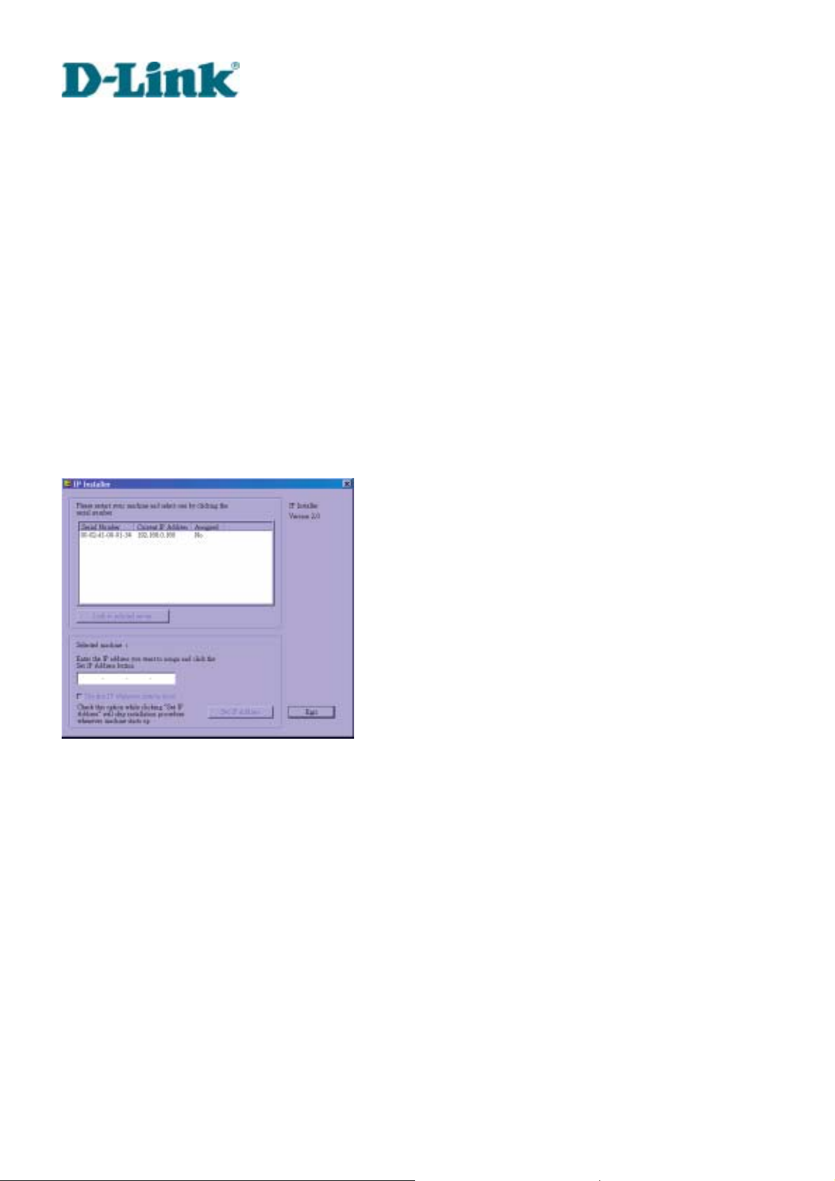
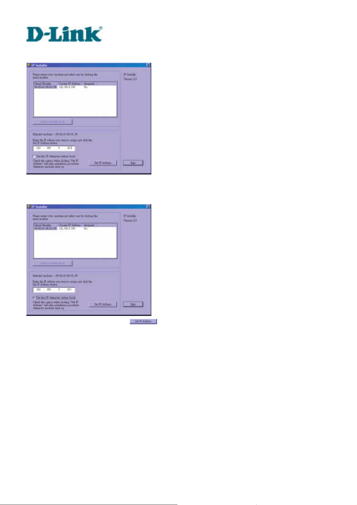
After the POST is done, Video Server will try to configure itself by detecting the network
environment. If there is DHCP service over the network, the Installer program will c atch the
given information and display the serial number and given IP address for each Video Server as
following figure. If no DHCP service is available, a previous IP address will be displayed instead.
In that case, it may be 0.0.0.0 for a brand new unit. When multiple units are mounted, there may
be several entries shown in the window. Administrators may click on each entry with "Assigned"
field labeled "No" to install sequentially.
DVS-301 User Manual v1.00
8
Page 15
Building Networks for People
The IP address shown in "Current IP Address" field is for the administrator's reference. If the
administrator wants to use another IP address, modify the IP text field below the list window.
If the administrator wants to fix the IP address of the unit, check the option "Use this IP
whenever system boots" to skip future installation procedures. Otherwise the unit will need
installation whenever it is restarted.
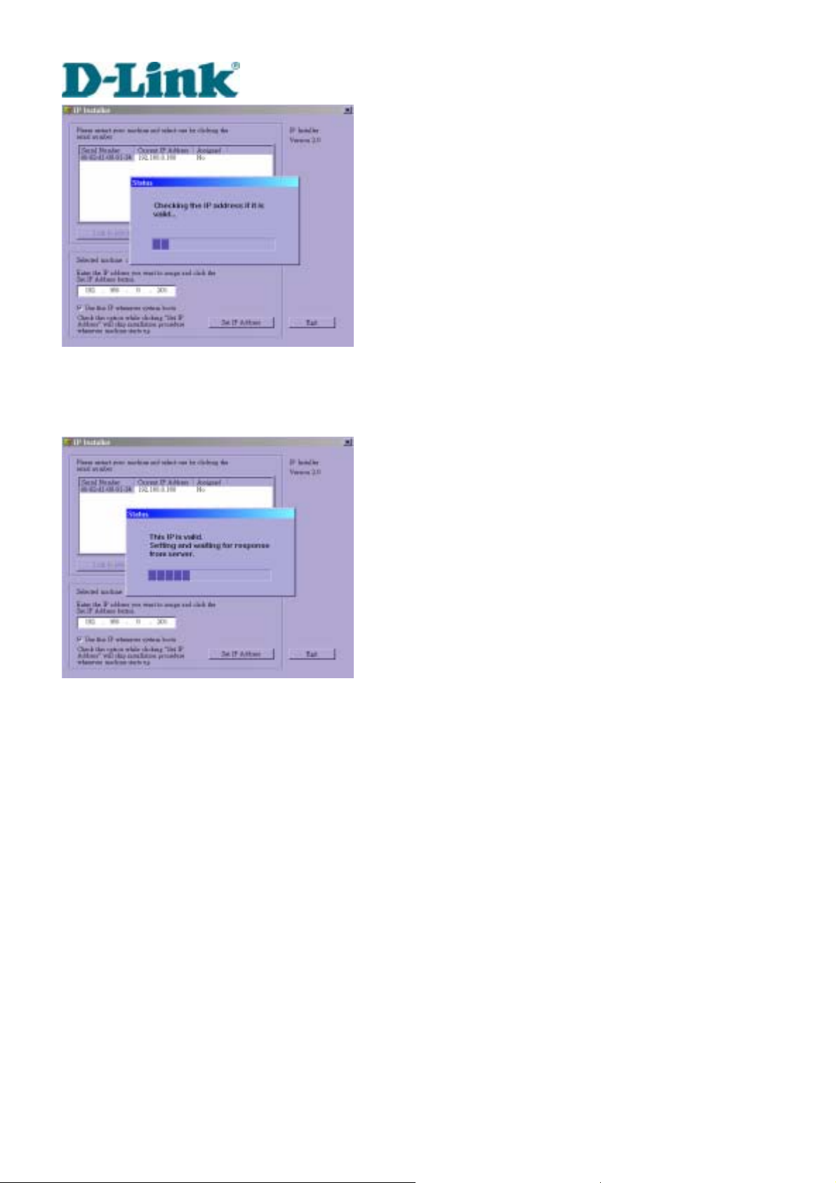
When IP and options are O.K., click on
. A message window will pop open to inform if
the IP address is valid.
DVS-301 User Manual v1.00
9
Page 16
Building Networks for People
If the IP is not taken by another network device in the network, the Installer program will
continue with the setup. Otherwise another message window will warn that the assigned IP
conflicts. In this case, administrators should ask the network supervisor for a vacant IP address.
DVS-301 User Manual v1.00
10
Page 17
Building Networks for People
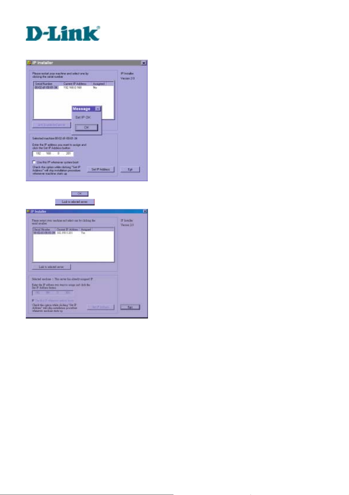
After successful notification, administrators may keep the address information for user’s
request.
After clicking on
directly on
, the "Assigned" field will be labeled "Yes". Administrators may click
to access the newly installed server in the default browser.
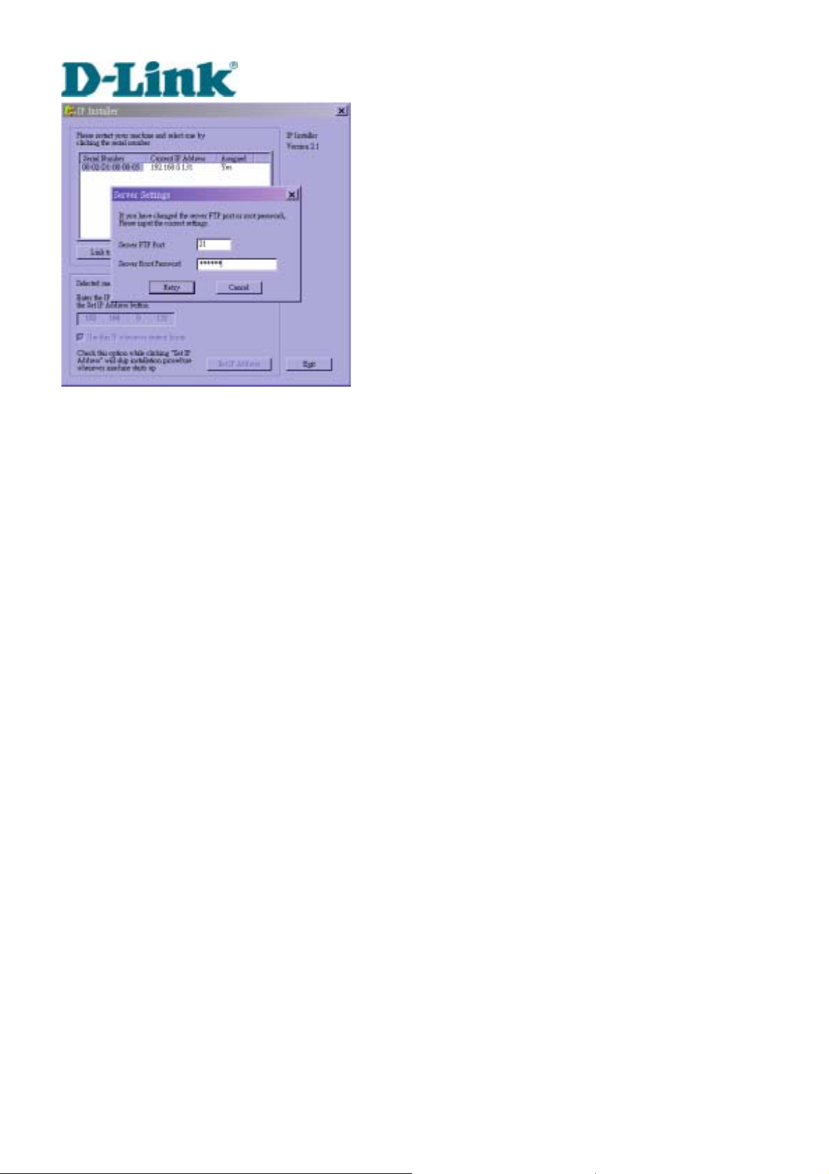
While checking “Use this IP whenever system boots”, a dialog window may pop out to ask for
“Server FTP Port” and “Root Password” because they are already changed to other than default
settings. If the settings are lost, restore default settings and use installer to install again.
DVS-301 User Manual v1.00
11
Page 18
Building Networks for People
Once installation is complete, administrators should follow the actions in the "First access to
Video Server" section for necessary checks and configurations. Experienced administrators
may use the customized config.ini script file to perform a quick setup via FTP. Detailed
procedure can be found on the section “One-shot fast configuration via FTP”.
To allow users to connect to Video Server through an easily memorized name, the
administrators must first configure the name server in his network. Here is an example: When
the administrator wants to set up Video Server with a fixed IP address and let users connect to
Video Server by typing a name instead of IP address, the administrator may reserve the IP from
DHCP service and assign it with name in the domain name service. During Video Server
installation, assign the ready IP address. After successful installation, users may access the
Video Server by the given name.
DVS-301 User Manual v1.00
12
Page 19

Building Networks for People
Manual way with existing programs
In addition to the provided installer program, some common network tools including ARP and
PING can be used to install Video Server. Open a DOS command prompt window to perform
the manual installation.
First, type arp –s “assigned IP address” “Ethernet address”
name table. The Ethernet address is identical to the serial number of Video Server and should
be typed in the appropriate format, with every two characters separated by a hyphen like
“uu-vv-ww-xx-yy-zz”.
Once a name entity is added, type ping "assigned IP address”
it replies, that means Video Server has accepted the assigned IP address and is ready for
access. The first several ping requests may fail during the self-configuration period of Video
Server.
to add an entity in the system’s
to invite the new Video Server. If
DVS-301 User Manual v1.00
13
Page 20

Building Networks for People
First access to Video Server
When connecting to Video Server for the first time, administrators should check security and
network settings on the configuration page. For complete protection from illegal usage, Video
Server provides two privileges and always needs user name and password before access. The
standard level is the USER mode that consists of twenty user profiles. Each user is able to
access Video Server except for system configuration. The twenty user profiles are also
maintained by the administrator. The highest level is ROOT mode that only opens to
administrators for initial setup, system configuration, user administration and software upgrade.
The user name of the administrator is internally assigned to “root”.
When connecting to Video Server, users will be requested for user name and password by an
authentication message window. A root password, identical to the Video Server's MAC address, is
needed for the initial access t o a newly installed Video Server. The administrator mu st change the root
password immediately after the initial in stallation to ensure securit y. The new root password should be
well memorized since there is no way to retrieve or recover it. After changing the password, the browser
will display an authentication window again to ask for the new password.
The other important part is network settings. The software configuration above makes Video
Server easily accessed through local networks. However administrators should review the
network settings on the configuration page according to the existing service. The safe and easy
way is to compare the network settings with another PC or workstation in the same network.
The software installation in the previous section only set the host IP address and default subnet
mask as 255.255.255.0. Administrators should change the subnet mask if it differs from the one
provided by server. Administrators should also fill in the default gateway, primary and secondary
domain name servers if necessary.
By default Video Server will need administrator's installation every time it reboots. If the network
settings are sure to work all the time, disable the install option if this IP address is already
reserved for this Video Server. Clearing this option will skip the installation procedure during the
next power-up and use the previous settings. If the install option stays checked, Video Server
will perform the installation procedure every time the system boots up.
Details about configurations are described in the "How to Use" section. Related figures are
attached for easy reference.
DVS-301 User Manual v1.00
14
Page 21

Building Networks for People
DVS-301 User Manual v1.00
15
Page 22

Building Networks for People
Modem Environment
Hardware installation
Before installing Video Server, the administrator should memorize the MAC address on the
packages respectively for the initial passwords.
To use a dial-up network, the Ethernet socket should be left disconnected since Ethernet is the
first priority among available interfaces. After powering up, Video Server will detect if any
external modem is connected to the modem port. Once a modem is detected, the heartbeat
LED will flash periodically. If no modem responds, Video Server will assume the included null
modem cable is connected to perform system configuration. Then both lower LEDs will turn on
until null modem connection is established.
If users have setup a remote dialup server or subscribed to an ISP service, Video Server can be
configured to dial to the server upon special events. Otherwise it will wait permanently for the
user’s call to establish a network connection to provide services.
In the following content, dial-in connection denotes a passive Video Server waiting for a phone
call to establish a point-to-point connection. Dial-out connection denotes an active Video Server
to dial out to the other end of a dial-up server or any Internet service provider, abbreviated as
ISP, to request a point-to-point connection.
DVS-301 User Manual v1.00
16
Page 23
Building Networks for People
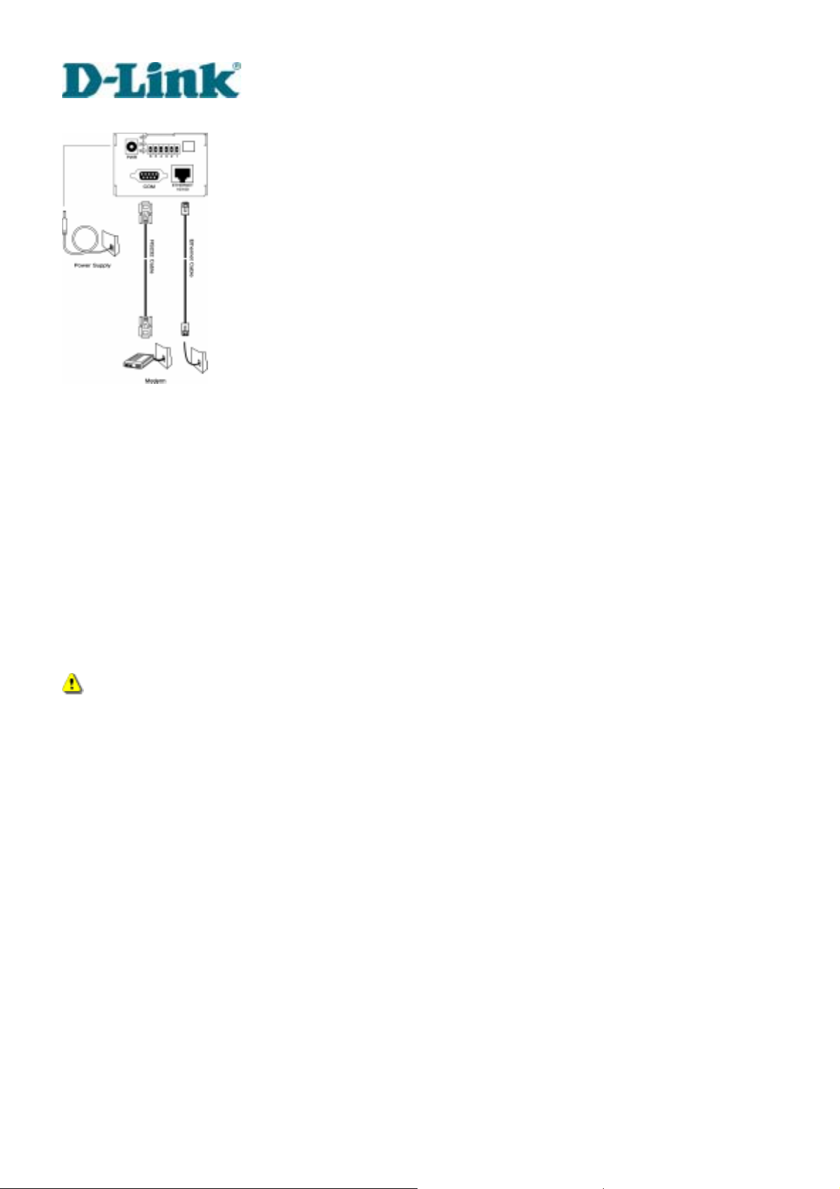
Cable connection
Shut down the peripheral devices prior to connection. Connect the supplied cables from Video Server to
the related devices according to following steps. Note that power adaptor must be kept unplugged until
other cables are firmly connected. For the first access to Video Server without Ethernet, administrators
may use the included null modem cable to connect to COM for direct connectio n. It is al so con venient for
administrators to access Video Se rver th rou gh the null modem cable directly without modem or Ethernet
card. After necessary information is entered, a modem can be used to dial into the Internet.
Power on
Make sure all cables are correctly and firmly connected. Turn on cameras, sensors, alarm
devices, and then finally attach power adaptor of Video Server to the electric power outlet*.
Since most automatic detections of hardware perform when the system starts, Video Server
should be turned on after all peripherals are turned on and ready.
Connect the power jack of th e power adapter to Video Server prior to plugging the utility
end into a utility power outlet. It will reduce accidental electric surge shock.
DVS-301 User Manual v1.00
17
Page 24
Building Networks for People
Software configuration
For the first time, users should connect the included null modem cable between the COM port
of Video Server and any COM port of the PC for initial setup.
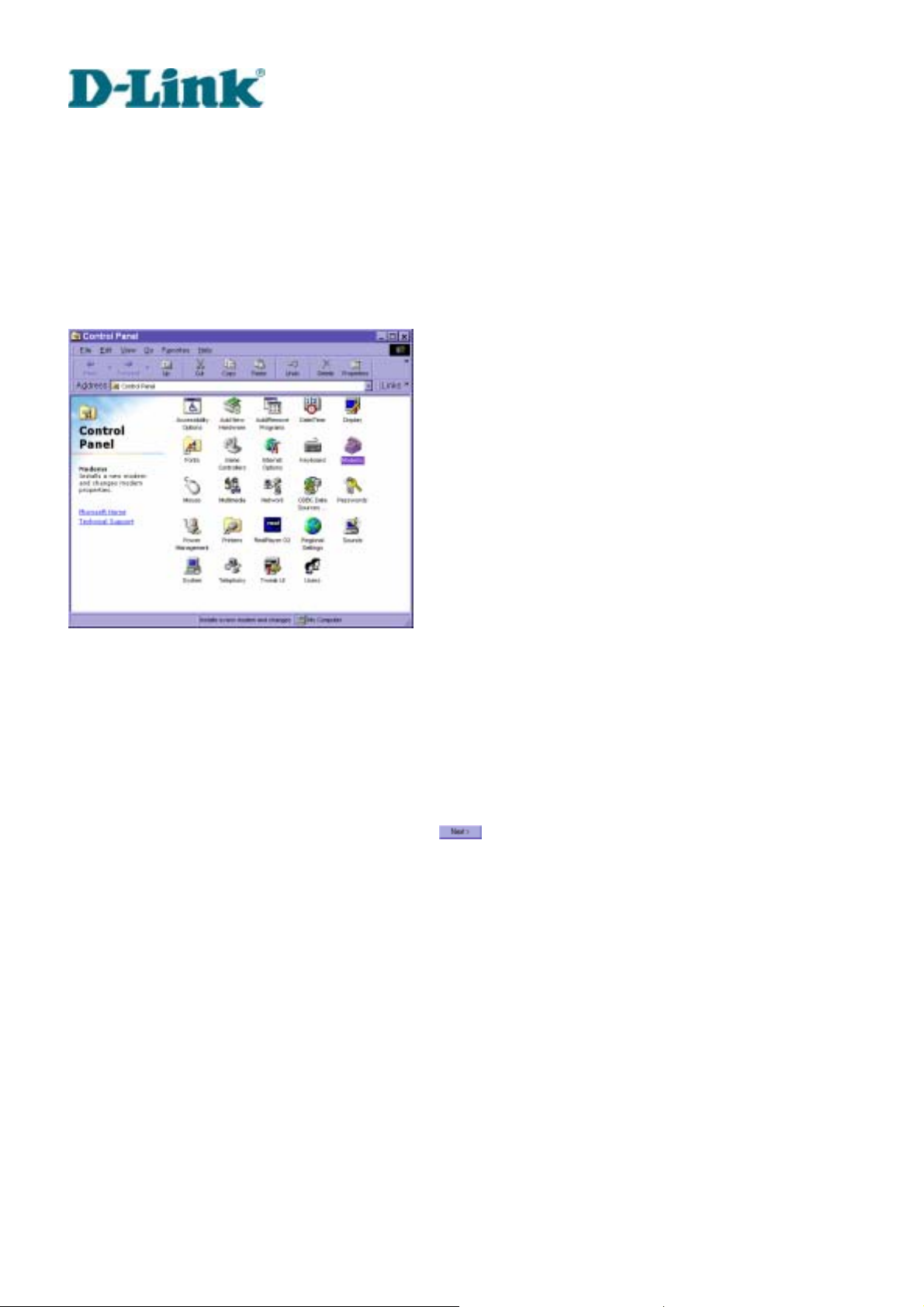
Install a new modem
Open the control panel and double click the modems icon.
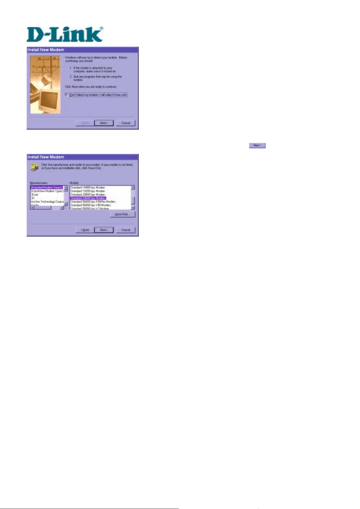
Check "Don't detect my modem......" item and click on
DVS-301 User Manual v1.00
18
to install a new modem.
Page 25
Building Networks for People
From (Standard Modem Type) choose the Standard 33600 bps Modem and click on
.
DVS-301 User Manual v1.00
19
Page 26
Building Networks for People
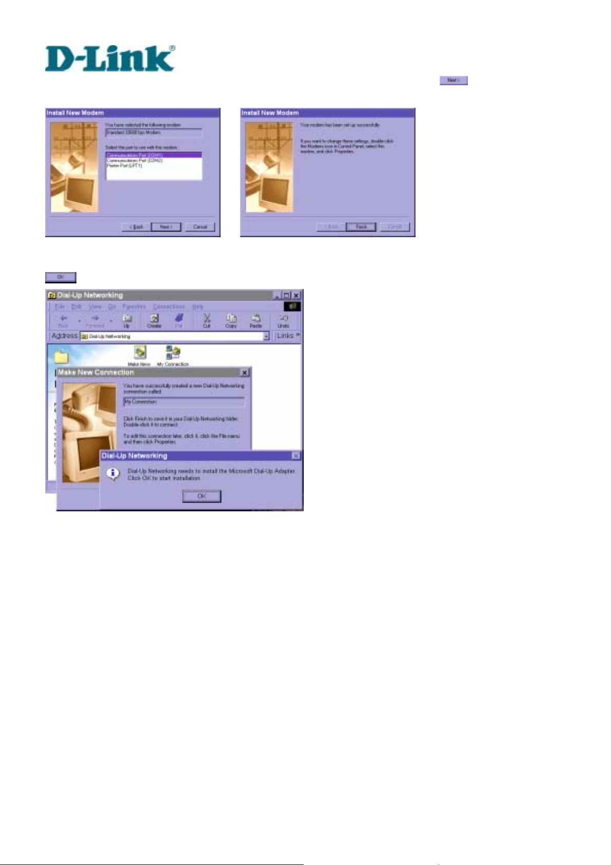
Choose the serial port that the included null modem cable is attached to and click on
The null modem is now ready for use.
If no Dial-Up adapter exists in the system, Windows will automatically prompt to install. Press
to continue.
.
DVS-301 User Manual v1.00
20
Page 27
Building Networks for People
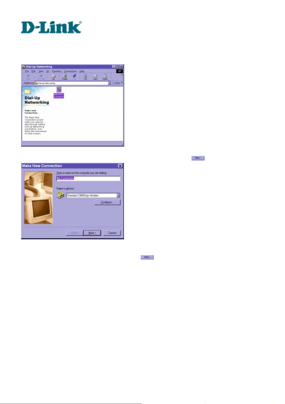
Setup a new connection
After the 33600 bps modem is installed, open the dialup network folder in Windows to build a
new connection.
Select the device as the newly installed standard 33600 bps modem and click on
.
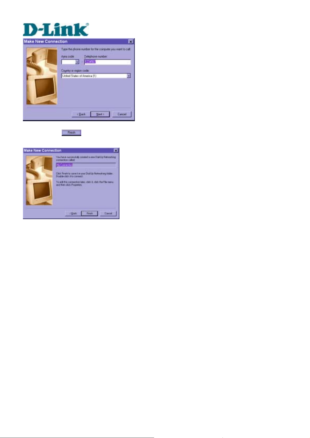
Just enter arbitrary digits as phone number and click on
. The phone number used here
is not important.
DVS-301 User Manual v1.00
21
Page 28
Building Networks for People
After clicking on
will be used for null modem connections.
, this new connection will display in the Dial-up Ne tworking folder and
DVS-301 User Manual v1.00
22
Page 29
Building Networks for People
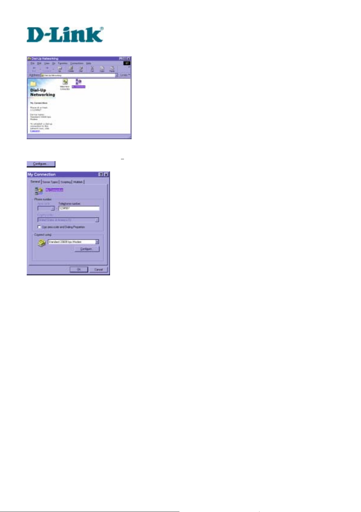
Right-click on the newly setup connection icon for properties.
In the first General page, clear "Us
.
e area code and Dialing Properties" option and click on
DVS-301 User Manual v1.00
23
Page 30
Building Networks for People
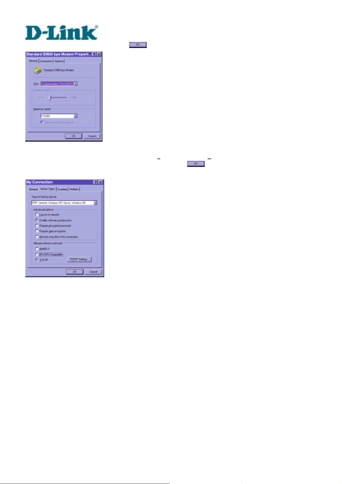
Select 115200 as the speed and click on
On the second page, only check "Enable software c
others blank. Keep other settings as default values and click on
ready for null modem connection.
.
ompression" and "TCP/IP" while leaving
. Now the connection is
DVS-301 User Manual v1.00
24
Page 31

Building Networks for People
Double click the newly setup connection. A dialing information window will pop up. Enter “root”
as user name and the MAC address labeled on the bottom side of the box as the password and
click on
may be changed by administrators after successful installation.
Notice that the letters in the MAC address should be capital form. For example, type 'A' instead
of 'a'. After some negotiation prompts, a connection status window will show the speed is
115200 bps.
. The user name and password are identical to what is used in web access and
After connection is established successfully, go to the next section, "First access to Video
Server".
If an error message indicates a hardware error while connecting for the first time, especially in a
Windows 2000 environment, try again to recovery the possible detection failure.
DVS-301 User Manual v1.00
25
Page 32

Building Networks for People
First access to Video Server
Through direct connection by null modem cable administrators can open the default web
browser and type in 200.1.1.1 as the address and press enter. Note that 200.1.1.1 will be the
default IP address in a dial-in connection and 200.1.1.100 will be the given IP address for the
user's PC by Video Server. The user name and password are the same as what was entered
during installation.
After successful authentication, administrators should see the motion pictures in the main page.
When using Microsoft Internet Explorer, administrators should allow a plug-in provided by Video
Server to install additionally. For best security, administrators must change the password on the
system page of configuration immediately. After changing the password, the browser will display
the authentication window again to ask for new password. Note that the new password will also
be used in the next dialup.
To make Video Server successfully work in dial-in and dial-out modes, follow the procedures
below for basic configurations. If people other than the administrator will be allowed to use
Video Server, the administrator should add these user profiles in the Security option. When
Video Server accepts dial-in connection and acts as a server, the user name and password
used in dialing are the same as what was stored in the user database managed for web access.
Any managed user can be authorized during PPP negotiation and access web pages. However
DVS-301 User Manual v1.00
26
Page 33

Building Networks for People
only administrators can access the configuration page.
There is more information needed for correct modem operation. Refer to the modem setting
section in configuration for further settings. Video Server will wait for someone to dial in. If the
administrator has setup some conditions in the application, Video Server will automatical ly dial
out based on the administrator's configuration. Refer to the application section in configuration
for special security applications. After everything is set and saved, turn off Video Server and
replace the null modem cable with modem for dial-up network. Since the null modem
connection is used to configure Video Server in advance for modem connection, administrators
cannot connect again without restarting the system.
If dial-out configuration is activated, Video Server will dial out to send a system startup log to
test and drop the call after the pre-configured period.
DVS-301 User Manual v1.00
27
Page 34

Building Networks for People
How to Use
Video Server is a well-designed stand-alone video server. With the built-in web server,
authorized users may use web browser Internet Explorer to watch the video and hear the audio
captured by Video Server. The powerful video compression processes up to 30 frames per
second and makes the scene in your browser as real-time display. The powerful audio
compression processes the real-time audio and makes the synchronization of video and audio
correctly. Also benefit from web interface, each f unction and each configuration has its specific
URL that allows advanced users easily integrate them into existing software program.
The preparation of the primar y users to utilize Video Server is quite simple since administrators have
done the majority of the installation. Most administrators find the installation is easy in general
environments because most settings are automatically configured. Open your web browser and connect
to Video Server just like a general we b site an d th e audio a nd vid eo will pr es ent on de ma nd. Ma ke sure
the web address of the target Video Server is accurate.
DVS-301 User Manual v1.00
28
Page 35

Building Networks for People
Authentication
After opening the Web browser and typing in the URL of Video Server, a dialogue window will
pop up to request a username and password. For administrator’s initial usage of Video Server,
enter the username as “root” and the password as the MAC address in capital letters. The MAC
address can be found on the labels under the body of Video Server and the top side of the
carton. The primary users will be allowed to enter as soon as the administrat or finishes adding
user profiles. Upon successful authentication, the main page will be displayed.
In the figure below, the foreground is the login window and the background shows the message
when authentication fails. The user may check the option to save the password for future
convenience.
If it is initial access to Video Server in Windows, the web browser will ask to install a new plug-in
that is provided by Video Server. This plug-in has not been registered for certificate and is used
to display motioned pictures in the browser. Users may click on
the web browser does not allow the user to install, check the Internet security option to lower
security levels or contact network supervisors.
DVS-301 User Manual v1.00
29
to install the plug-in. If
Page 36

Building Networks for People
DVS-301 User Manual v1.00
30
Page 37

Building Networks for People
Primary user’s capability
Main screen with camera view
There is a logo image shown in the upper left corner. It can link to other web sites or resources
depending on the settings in configuration. The assigned caption and system date/time will display in the
banner above the image window. There might be some windows enclosed by red lines shown in the
image as soon as motion is detected in the related windows. Click on the configuration link to the right of
the image window to enter the configuration page.
DVS-301 User Manual v1.00
31
Page 38

Building Networks for People
PTZ camera control
A PTZ motorized camera is provided by customers and should be correctly installed in advance.
The control button under the video allows users to control the motorized camera attached to
Video Server with pan/tilt direction and zoom. To access the location set previously, pull down
the Preset Position list to select one and click on
camera locations. Primary users are only allowed to browse the preset locations. Five buttons
below the image can be used to control cameras in ways other than pan, tilt and zoom. They
should be pre-configured by administrators with reference to the instruction manual of the
cameras.
. Only the administrator can preset the
<url> http://<Video Server>
<Video Server> is the domain name or pure IP address of Video Server.
Client Setting
If it is the first access to “Client Setting” page in Windows, the web browser will ask to install a
new plug-in that is provided by Video Server. This plug-in has not been registered for certificate
and is used to setting the client parameters in the browser. Users may click on
the plug-in. If the web browser does not allow the user to install, check the Internet security
option to lower security levels or contact network supervisors.
DVS-301 User Manual v1.00
32
to install
Page 39

Building Networks for People
There are two settings for the client side. One is “Media Option”. You can mute the audio by
checking this option. The other is “Protocol Option”. You can choose the connection protocol
between client and server by this option. There are three protocols - UDP, TCP and HTTP.
When you choose UDP protocol, audio and video streams can be more real-time. But some
packets may be lost and decoding error will happen. If you select TCP protocol, p acket loss isn’t
occurred and decoder will run normally. But the real-time issue is worse than UDP protocol. If
your environment is behind the firewall and it opens HTTP port (80) only, you can select HTTP
protocol only. In this mode, audio will not be sent and you just can see the video only. If you
don’t know which protocol you should choose, select the UDP protocol and the client will try
these protocols in this order, UDP → TCP → HTTP. After the client connects to the Video
Server successfully, “Protocol Option” will be set as the working protocol au tomatically.
DVS-301 User Manual v1.00
33
Page 40

Building Networks for People
<url>
http://<Video Server>/client.html
<Video Server> is the domain name or original IP address of Video Server.
When using modem as the network connection, Video Server will not send the audio
automatically, and send video only because the low bandwidth environment doesn’t meet the
requirement for both. In the Client setting page, protocol option will be set as Http protocol.
System configuration
There are two methods provided for configuration. Web interface is quite easy and clear to use
and FTP with script file is rapid for mass installation. System configuration can be accessed
only by administrators. Administrators may type the URL below the figure to directly enter the
configuration page. If administrators also want to set certain options through the URL, read the
section on advanced usage for reference.
DVS-301 User Manual v1.00
34
Page 41

Building Networks for People
<url>
http://<Video Server>/setup/config.html
<Video Server> is the domain name or original IP address of Video Server.
DVS-301 User Manual v1.00
35
Page 42

Building Networks for People
System parameters
To change the system name, type in the text box after "Host Name". This name will be
displayed at the top of the main page. In the case that only the host name is changed, without
adjusting date and time of Video Server, click on "Keep current date and time".
There are three ways to adjust system date and time. The easiest is to make Video Server
"sync with computer time". The second is to set the date and time manually. Notice the format
in the related field while typing. The third is to make Video Server automatically synchronize
with timeservers over the Internet whenever Video Server starts up. It may fail if the assigned
NTP server cannot be reached or it is within a local network. Leaving the NTP server blank will
let Video Server connect to default timeservers. If some specific timeserver is assigned, type it
in the text box. Domain name or IP address format is acceptable as long as DNS server is
available. Do not forget to set the "Time Zone" offset for local settings. It only affects the hour in
NTP method. Click on
to validate changes.
When user sets the illegal range of Date or Time, server will not accept this new setting and
restore to the last setting. The legal range of year is between: 2000~2035.
DVS-301 User Manual v1.00
36
Page 43

Building Networks for People
User group administration
To change the administrator ’s password, type the new password in both text boxes identically.
What is typed will be displayed as asterisks for security purposes. After pressing
browser will ask administrators for the new password for access.
To add a new user, type the new user's name and password and press
to insert the entry.
There are a total of twenty user accounts. Since only administrators can change a user's
password, confirmation for a user's password is not necessary.
To delete a user, pull down the user list to find the user name to be deleted and press
, the web
.
DVS-301 User Manual v1.00
37
Page 44

Network settings
Building Networks for People
Any change made to this page will make the system restart to validate. Make sure every field is
correctly typed before clicking on
.
To eliminate incautious mistakes during installation, Video Server will stay in installation mode
whenever it starts unless "Reset network at next boot" is disabled. This option can also be
disabled using the Installer program. Once the option is disabled, Video Server will skip
installation at the next boot and the Installer program will not find the installed units. That implies
that Video Server cannot be accessed if no one remembers the IP address, except by restoring
factory default settings. However, with this option disabled Video Server can automatically
operate normally after restarting in case of losing power. This option is ignored in the PPP
connection.
Administrators may modify the network settings to fit into existing networks. Some broadband
service subnet mask may differ from the default value 255.255.255.0 and service providers may
assign some specific network settings. Administrators should change the configuration
according to what is given by the service provider. The configuration may include "IP address",
DVS-301 User Manual v1.00
38
Page 45

Building Networks for People
"Subnet Mask", "Default Router", "Primary DNS" and "Secondary DNS". After changing
network settings, be sure to leave "Reset network at next boot" blank to skip installation when
the system restarts. Otherwise the settings will be erased.
Video Server not only plays the role of server, it will also actively connect to servers outside to
send out messages or snapshots. When Video Server starts, it will send out a system log to
notify administrators. Even in modem application, Video Server will send out a connection log
whenever it dials out to an ISP or dialup server outside. If the administrator has setup some
applications in either event mode or sequential mode, Video Server will send out snapshots
once conditions are met. There are two methods to send files, including e-mail and FTP. To
ensure Video Server sends out files correctly, administrators should set valid "SMTP (mail)
server" and "Recipient email address" as well as "Pri mary FTP Server", "Primary FTP user
name" and "Primary FTP password". “Return email address” is whom the mail will return
when the SMTP server rejects upon any failure. Some ISP may reject the mail if the address is
invalid. "Primary FTP remote folder" is the relative sub-folder in the remote FTP server.
In both methods, a "Secondary" server can be provided for backup connection. However the
primary server information should be entered first. If the primary server is not set, the related
FTP or email will be deactivated. Note that it may take time to connect to the secondary server
after the first one fails and it may affect some applications when conditions happen too often.
For security or network integration, administrators also can hide the server from the general
HTTP port by changing "HTTP port" to other than default 80. “Local FTP serv er port” can also
be changed to other than default 21. These ports of “Control Channel Port”, “Audio Channel
Port” and “Video Channel Port” which are used in media transmission can also be cha nged.
Administrators should have enough acknowledge before changing the default port.
If the Video Server works in variation or low bandwidth (comparing with video bandwidth)
environment, the client side will receive the poor quality o f media. For improving this situatio n,
you can check the “
audio quality better, but the media delay is longer and real-time issue is bad. If the network performance
is worst, please select the ”UDP protocol“ as the communication protocol in “client setting”
After everything is set, click on
Video Server will automatically restart. If "Reset network at next boot" is kept checked, run the
installer procedure again. Otherwise Video Server will restart automatically.
Improve audio quality in low bandwidth enviro nment” item. It can make the
. A warning message will pop up. Click on to confirm.
DVS-301 User Manual v1.00
39
Page 46

Building Networks for People
Administrators should notice that the IP address, subnet mask, default router and DNS servers
will be cleared when the network interface is switched to the other. Refer to the related section
of Ethernet or modem for software installation.
DVS-301 User Manual v1.00
40
Page 47

Building Networks for People
Video codec parameters
Options on this page will affect the image on the main page seen by users. "Text on Video" will
be displayed above the video window with a timestamp. The timestamp is captured from date
and time of Video Server that is maintained by a built-in real-time clock. "Color" setting is
independent of the connected camera and B/W option might speed up the encoder a little.
"Size" option allows users to adjust the image size taking into consideration bandwidth and
visual effect. Three options are available including half, half×2 and normal. Half×2 consumes
the same bandwidth as half but is the same size as normal. Of course the image is not as good
as normal. Half×2 is especially suited to low bandwidth environments like a dial-up network.
The "Modulation" type is auto-detected during initialization, but administrators can still set it
manually.
DVS-301 uses MPEG4 codec compression for best streaming solution. The compressed video
data is far less than JPEG in normal cases but it still depends on the level of difference between
every two sequential images. There are three dependent parameters provided for adjustment.
"Maximum Frame Rate" limits the maximal refresh frame rate that can be combined with the
"Video Quality Control" to optimize the bandwidth utilization and video quality. If users want to
fix the bandwidth utilization regardless of the video quality, choose "Fix Bit Rate" and select the
DVS-301 User Manual v1.00
41
Page 48

Building Networks for People
desired bandwidth. The video quality may be poor in order to send maximal frames within the
limited bandwidth when images change drastically. Consequently to ensure the video
quantization rate regardless of the bandwidth, it will utilize more bandwidth to send the maximal
frames when images change drastically.
The option "Enable Motion Detection" will control the event of motion detection on the
application page. If this option is enabled, the preset windows framed by red lines will appear in
the video window even if no option is checked on the application page. If this option is disabled,
then any settings related to motion detection will have no effect. Motion detection will increase
system load. Enter the motion detection option page for advanced configuration.
To adjust video from external cameras, use "Flip" to map the video vertically and "Mirror" to
map the video horizontally.
DVS-301 User Manual v1.00
42
Page 49

Building Networks for People
To adjust image settings for best visual quality, press
and a motion picture
window will pop up for your reference. There are four fields including "Brightness", "Contrast",
"Hue" and "Saturation" for video compensation. . Each field has eleven levels ranged from -5
to +5. The user may press to fine-tune the image. When the image is O.K., press
to memorize the image settings or
to recall the original settings. If parameters are
changed without saving, they will be used until the next system startup.
Motion detection
Please note that the option "Enable Motion Detection" on the video page must be enabled to
make detection effective.
Video Server allows administrators to define at most three detection windows to cover different
DVS-301 User Manual v1.00
43
Page 50

Building Networks for People
areas. To monitor a specific area, click
Name" will show at the top of the window. Use the mouse to drag the border to the desired size
or title bar for location. Higher sensitivity and small percentage will make motion easier detected
easier and vice versa. After clicking
image variation. A green bar means the image variation is under monitoring level and a red bar
means the image variation is over monitoring level.
to add a new window. The typed text in "Window
, a graphic bar will go up or down depending on the
DVS-301 User Manual v1.00
44
Page 51

Building Networks for People
The following figure shows the screen when
marked by red squares.
is clicked. The monitoring windows will be
DVS-301 User Manual v1.00
45
Page 52

Building Networks for People
PTZ camera configuration
Since Video Server can be used in either Ethernet network or PPP network, the single serial
port can be used to control either external COM port devices like a PTZ camera or modem.
While in PPP interface, go to Modem page for modem configuration. Options on this page will
be ignored.
Video Server supports RS232 and RS485 interfaces to control external serial port devices.
Refer to the hardware description to connect an RS485 device. The included camera control
cable can be used for Sony or Canon cameras. The choice "Auto Detect Driver" in driver
option will let Video Server detect the supported camera models sequentially from RS232 to
RS485.
Administrators can pull down the list to select UART "Interface Mode" according to the
connected device and select the camera model directly to save time in detection.
Video Server can support any other custom camera by selecting "Custom Camera" type. If the
attached device is not a PTZ camera, a specific URL can be utilized as an alternative method.
See the advanced section for details.
DVS-301 User Manual v1.00
46
Page 53

Building Networks for People
To preset the camera head position, press
and another window will pop up with
the camera view and control buttons for preview. After moving it to the desired position, enter
the preset position name and click on
. Note that if improper characters are used in the
position name, a warning message window will pop up.
To delete the previously preset position, pull down the position list to find the position name and
press
.
DVS-301 User Manual v1.00
47
Page 54

Building Networks for People
Video Server provides five more custom commands other than general pan, tilt, zoom and
preset functions. Administrators can click on
manual of the attached device to setup frequently used functions. The "Commands" should be
entered in ASCII format; Video Server will translate it into binary code and send it out through
the serial port. For instance, a text string of "8101ABCDEF" will be translated into five bytes of
hexadecimal 81, 01, AB, CD and EF. The maximal len gth of a command string is 60 which is
equivalent to 30 hexadecimal bytes. "Display string" is for text on command buttons and
should be less than 8 characters.
and refer to the instruction
DVS-301 User Manual v1.00
48
Page 55

Building Networks for People
If the attached motorized camera is not on the support driver list, choose the proper UART
interface and pull down the driver list to select Custom Camera type and click on
for further configuration.
Setup the serial "Port Settings" according to the instruction manual of the custom camera. The
"Baud Rate (bps)" of the serial port is up to 115200 bps. Then enter the specific command
related to PTZ in the respective field. The custom command for "Control Setting" should be
edited in ASCII format. Video Server will interpret the ASCII format command to binary string.
For instance, “012000ABCD” will be sent out of the COM port as five hexadecimal bytes of 01,
20, 00, AB and CD. If the command string is composed of two or more commands, a comma ‘,’
should be inserted to separate each command. Each comma represents 200 milliseconds. For
instance, a command to pan left may be “01000305” and a command to stop panning may be
“01000300”. The user may edit the applicable command as “01000305,01000300” in the Move
Left field. This means the camera will pan left for 200 milliseconds. When everything is set, click
on
Double-check the driver settings and then click on
custom camera. Since changing drivers will restart the system, a message window like the
following figure will pop up to confirm your actions. The system will restart right after clicking on
to save the commands and click on to close the command setting window.
to save the configurations of the
DVS-301 User Manual v1.00
49
Page 56

Building Networks for People
.
DVS-301 User Manual v1.00
50
Page 57

Building Networks for People
Modem and dialup settings
In PPP interface, a modem option will work instead of camera control. Configurations include
modem initialization and outside dial-up server. If the users will setup with external sensors and
alarms for property security, dial-out is needed to send some snapshot-attached e-mails when
the preset conditions are triggered. In such applications, also remember to choose Network
option to enter mail server address and recipient's e-mail address. If "Dialout allowed" is not
checked, Video Server will not send out any snapshots when events occur and the settings
except for "Initial modem command" in this page will have no effect. The system will preset
the attached modem to eliminate echo and mute line sound. To initialize the modem with further
commands, type into the edit box. The prefix "AT" should be included.
Administrators should choose an appropriate "Dial Method" according to the local POTS
environment. An incorrect dialing prefix may cause Video Server to fail when dialing out.
"Redial attempts" means how many times Video Server should try to connect to each ISP.
Setting the value in "Disconnect after minutes" will force Video Server to drop the connection
when there is no activity on the connection for the specific period. The range of this period is
from 1 to 240 minutes, with 0 indicating a continuous connection. Administrators may let Video
Server keep the connection for a while to allow connections from outside. The IP address given
by the ISP can be taken from the connection log that is mailed or uploaded when dial-up
connection is successful. Setting the value to zero will make Video Server always keep the
DVS-301 User Manual v1.00
51
Page 58

Building Networks for People
connection.
Based on the settings of DI/DO in the application, the system will send mail or upload via FTP
with image attachment upon the event occurring. In that case Video Server will need a network
connection and automatically dial out to the pre-configured server outside. When a connection
is successfully established, Video Server will send out a connection log to notify given network
settings. For those installations that may switch the network interface between Ethernet and
PPP, administrators should notice that the settings of FTP or SMTP servers might be different
from what is in an Ethernet environment. If the network interface is changed, administrators
may need to configure them in advance.
Video Server will try the second ISP as a backup when the first ISP fails and exceeds the redial
attempts. "ISP phone number" should be the complete phone number including country code
and area code if necessary. "Login username" and "Login password" are used to pass the
PPP negotiation requested by the ISP server. Note that the pair of login name and password is
dependent on the ISP and is different from what is used in the authentication process in web
access.
When using modem as the network connection, Video Server will mute the audio
automatically, and send video only because the low bandwidth environment doesn’t meet the
requirement for both. In the Client setting page, protocol option will be set as Http protocol.
DVS-301 User Manual v1.00
52
Page 59

Building Networks for People
Application
Administrators can use combinations of options on the application page to perform many useful
security applications. The sending method is selected at the bottom of the page. Both e-mail
and FTP use the network settings on the network page. To use FTP to upload snapshots, a
timestamp file name can help administrators identify the event. If "FTP put snapshot with date
and time suffix" is disabled, the up-to-date snapshot will overwrite the file.
There are two application methods to upload snapshots. "Sequential operation" will send out
snapshots continuously over a configured period. This mode can be used to integrate with
another web server to serve overloaded requests. If the date and time suffix option is disabled,
Video Server can use FTP to upload and overwrite snapshot files periodically. The remote
folder of snapshot files for FTP can be configured on the network page. The snapshot period is
between "Snapshot begin" and "Snapshot end" and it will repeat everyday. The snapshot
interval is set in "Snapshot every seconds".
The other "Event operation" can be used to combine motion detection with devices attached to
digital input, to drive devices attached to digital output, or send out snapshots for evidence. It
helps users establish an easy security system. Administrators may choose any combination of
conditions to form special applications according to their personal needs. Video Server will
continuously monitor the channel and digital input every half second. Once the user-defined
DVS-301 User Manual v1.00
53
Page 60

Building Networks for People
conditions are matched, Video Servers will capture three stages of events and react based on
the "Trigger action" settings. The post-event snapshot can be configured to be delayed after
events happen according to the setting in "Take snapshot at seconds after event". The three
stages of snapshots will be VPRE.JPG, VTRG.JPG and VPOS.JPG. Since the same event may
exist for a while, administrators can set delay time in "Delay seconds before detecting next
event" to reduce multiple triggers by the same event.
There are two kinds of "Trigger condition". For digital input there are four options provided to
combine with the user's device. Rising and falling will make events happen once. For motion
detection, there are window names shown below as choices. Refer to the previous section for
configuring motion detection. Note that larger object size and lower sensitivity will make it more
difficult for Video Server to detect varied images. Once the "Trigger condition" is matched,
Video Server will drive the digital output device and/or upload snapshots based on the "T rigger
action" settings. The application settings should be carefully examined to operate accurately. If
administrators are not sure of the digital output status before configuring applications, "Reset
output" can be used to return the digital output to the default “Normal Close” state.
DVS-301 User Manual v1.00
54
Page 61

Building Networks for People
Homepage layout settings
Administrators may give Video Server a different presence of homepage. The "logo graph" for
the system logo in the upper-left corner can be hidden; or the default image from the system
memory can be used; or an external resource can be used by assigning a URL. "background
graph" is similar. Default images from system memory are quick to get but limited by memory
size. Images from external resources can be larger and more beautiful but will need more time
to load. If the background is skipped, the background color will fill the browser window.
Administrators also can give the system logo a "logo link" to refer to another web site. The
"font color" and "background color" can be chosen from sixteen colors to achieve the best
visual effect.
See "Customizing homepage images" section in "Advanced functions" for how to replace
images.
DVS-301 User Manual v1.00
55
Page 62

Building Networks for People
One-shot fast configuration via FTP
For quick setup of Video Server, the administrator can utilize the default CONFIG.INI that may
be downloaded from the FTP daemon of Video Server. To log into the FTP daemon, enter “root”
as the user name and the same password used when connecting to the Web server. The MAC
address of Video Server is the password for the initial access.
Then administrators only need to modify necessary fields and then upload the file to Video
Server with the file name “CONFIG.INI”. To reduce error in interpretation, it is recommended
that the downloaded template CONFIG.INI be modified using the options following each item in
the sample below. The file will include seven categories: [SYSTEM], [NETWORK], [VIDEO],
[SERIAL], [ALERT],and [LAYOUT]. The category name in brackets should be in upper case.
The item name in angle braces should be in lower case. Some items related to disable/enable
should use the keywords “YES”/“NO”. The number zero entry in <user name> and <user
password> is for the administrator, i.e. “root”.
Since the password when logging into FTP is not encrypted, it is recommended to use the Web
instead of FTP to configure the system afterwards. If some parameters other than the network
or camera drivers are changed, administrators can set <reset system> to NO to avoid rese tting
the system. It will automatically return to YES during the next downloading of CONFIG.INI.
A sample CONFIG.INI is attached below. The italic text following each line describes the format
of the field and the bold italic characters are the possible values of each field.
******* sample file **********
Video Server Initial Configuration File
[SYSTEM]
<reset system>
YES or NO
<host name>
Video Server String shorter than 40 characters
<serial number>
0002D1000001 Read only string
<software version>
IP2001-1A-5168-0101 Read only string
<current date>
2001/08/14 year/month/date. Read only string
<current time>
DVS-301 User Manual v1.00
56
Page 63

Building Networks for People
07:00:00 hour/minute/second. Read only string
<time zone>
0 From 12 to -12
<user name>
(0) root Read only string
(1) String shorter than 15 characters
(2) The followings are as same as above
(3)
(4)
(5)
(6)
(7)
(8)
(9)
(10)
(11)
(12)
(13)
(14)
(15)
(16)
(17)
(18)
(19)
(20)
<user password>
(0) 0002D1000001 Initial value is as same as serial number
(1) String shorter than 15 characters
(2) The followings are as same as above
(3)
(4)
(5)
(6)
(7)
(8)
(9)
(10)
(11)
DVS-301 User Manual v1.00
57
Page 64

Building Networks for People
(12)
(13)
(14)
(15)
(16)
(17)
(18)
(19)
(20)
[LAYOUT]
<font color>
1 color index: 0 for black, 1 for white, 2 for green,
<background color> 3 for maroon, 4 for olive, 5 for navy, 6 for purple,
0 7 for gray, 8 for yellow, 9 for lime, 10 for aqua,
11 for fuchsia, 12 for silver, 13 for red, 14 for blue,
15 for teal
<logo type>
1 0 for blank, 1 for default image or 2 for loading from URL
<background type>
1 0 for blank, 1 for default image or 2 for loading from URL
<logo source>
http:// link to external resour ce when logo type is 2, no longer than 80
<background source>
http:// link when background type is 2, no longer than 80
<logo link>
http://www.xxx.com providing external link when clicking on logo, no longer than 80
<com speedlink name>
(0)AT on/of no longer than 8 characters(some language will use double
bytes)
(1)AT bg/ed no longer than 8 characters(some language will use double
bytes)
(2)AT mode no longer than 8 characters(some language will use double
bytes)
(3)bklt on no longer than 8 characters(some language will use double
bytes)
(4)bklt off no longer than 8 characters(some language will use double
DVS-301 User Manual v1.00
58
Page 65

Building Networks for People
bytes)
[NETWORK]
<install enabled>
YES or NO
<ppp enabled>
YES obsolete
<ethernet address>
00-02-D1-00-00-01 Read only string
<host ip>
192.168.0.201 Standard IP format
<subnet mask>
255.255.255.0 Standard IP format
<gateway ip>
192.168.0.254 Standard IP format
<primary name server>
192.168.0.1 Standard IP format
<secondary name server>
168.95.1.1 Standard IP format
<ntp enabled>
YES or NO
<network timing server>
ntp-cup.external.hp.com Standard IP format or string shorter than 40 characters
<smtp mail server>
Standard IP format or string shorter than 40 characters
<mail recipient address>
String shorter than 80 characters
<mail return address>
String shorter than 80 characters
<backup smtp mail server>
Standard IP format or string shorter than 40 characters
<backup mail recipient address>
String shorter than 80 characters
<ftp server>
Standard IP format or string shorter than 40 characters
<ftp username>
String shorter than 15 characters
DVS-301 User Manual v1.00
59
Page 66

Building Networks for People
<ftp password>
String shorter than 15 characters
<ftp init path>
/ String shorter than 40 characters
<backup ftp server>
Standard IP format or string shorter than 40 characters
<backup ftp username>
String shorter than 15 characters
<backup ftp password>
String shorter than 15 characters
<backup ftp init path>
/ String shorter than 40 characters
<http server port>
80 Integer less than 1024
<control channel port>
5001 Integer less than 65535
<control channel port>
5002 Integer less than 65535
<control channel port>
5003 Integer less than 65535
<low bandwidth environment>
NO or YES
[VIDEO]
<camera modulation>
AUTO or MANUAL. NTSC or PAL will be ignored when AUTO
NTSC or PAL, ignored when AUTO but can be notification
<caption text>
String shorter than 15 characters
<colored video>
YES or NO
<video quality>
8 12, 10, 8, 6, 4 representing Medium, Standard, Good, Detailed, Excellent
<brightness>
0 among 5 and -5
<contrast>
0 among 5 and -5
DVS-301 User Manual v1.00
60
Page 67

Building Networks for People
<hue>
0 among 5 and -5
<saturation>
0 among 5 and -5
<rate control>
YES for fix bit rate, NO for fix quality
<bit rate>
384k 1200k, 1000k, 768k, 512k, 384k, 256k, 128k, 64k
<frame rate>
30 1, 2, 3, 5, 10, 15, 20, 25, 30 (30 for NTSC only)
<video size>
3 1, 2, 3 representing half, halfx2, normal
<motion detect enabled>
NO
<flip>
NO
<mirror>
NO
[SERIAL]
<auto detect camera>
YES or NO
<data bits>
8
<stop bits>
1
<parity bits>
0
<baud rate>
9600
<ccd model>
0 0, 1, 2, 3, 4, 6, 7 representing NONE, Custom came ra, Sony EVI-D30, Canon
VCC1, Canon VCC3, Dynacolor Dome and Pelco Camera
<uart mode>
RS232 or RS485
<speedlink commands>
(0) String shorter than 80 characters
DVS-301 User Manual v1.00
61
Page 68

Building Networks for People
(1) String shorter than 80 characters
(2) String shorter than 80 characters
(3) String shorter than 80 characters
(4) String shorter than 80 characters
<custom ccd commands>
UP
String shorter than 80 characters
DOWN
String shorter than 80 characters
LEFT
String shorter than 80 characters
RIGHT
String shorter than 80 characters
HOME
String shorter than 80 characters
TELESCOPE
String shorter than 80 characters
WIDE
String shorter than 80 characters
NEAR
String shorter than 80 characters
FAR
String shorter than 80 characters
[ALERT]
<application mode>
0 for none, 1 for sequential mode, 8 for event mode, 9 for both
<upload method>
0 0 for FTP, 1 for email
<file with time suffix>
YES or NO
<seconds to snapshot after event>
0
<seconds to snapshot periodically>
0
<time to start snapshot>
00:00:00 24 hours format
DVS-301 User Manual v1.00
62
Page 69

Building Networks for People
<time to stop snapshot>
00:00:00 24 hours format
<seconds delay before next event>
3
DVS-301 User Manual v1.00
63
Page 70

Building Networks for People
Advanced functions
Web
Viewing system log
Click the button on the configuration page to view the system log file. The content of the file
reveals useful information about configuration and connection after the system boots up.
Viewing system parameters
Click the button on the configuration page to quickly view the whole system parameter set. The
content is the same as CONFIG.INI.
Restore factory default settings
Click the button on the configuration page to restore the factory default settings. This means
any changes made before will be lost and the system will be reset to the initial status when
shipped from the factory. After confirmation, the system will restart and require the installer
program to setup the network.
Clear data path for proprietary commands
Video Server provides a highly customized control support to third-party serial interface devices
aside from PTZ cameras. That means in addition to setting up a custom camera with PTZF
commands, users may utilize this mode and introduce a customized homepage to transmit
arbitrary user-defined commands from the user-side to Video Server. The third-party device
connected to the serial port of Video Server will receive the same command sent by the
originator. The user only needs to attach the command in ASCII format after the special URL.
Video Server will parse the command and transfer into binary code to send out. See the clear
data mode serial port driver in the URL commands of Video Server section for detailed
description.
DVS-301 User Manual v1.00
64
Page 71

Building Networks for People
FTP
Video Server not only has web service for easy access but also has a built-in FTP service to
make system integrators easy to use. According to settings on the application page, Video
Server can sequentially send updated snapshots over a specific period to an external server
with choices of overwriting and time suffix. For security staff, Video Server can directly send
snapshots to an external server as evidence according to event settings. Through Video
Server’s FTP daemon, administrators can quickly update configurations and maintenance.
Those files with GIF extensions which are used for a homepage layout and can be read and
overwritten. They also can be downloaded by managed users. Other files will be explained
below.
Uploading snapshots periodically to an external FTP server
In sequential mode, Video Server will send out snapshots according to interval and period
settings. If snapshot files are intended for quick updates, it is better to skip date and time suffix.
The file name will then be video.jpg. If the snapshots are used for occasional monitoring, suffix
with date and time can help administrators classify them easily.
Customizing homepage images
There is a small icon before each link that can be changed by administrators. Administrato rs
may change the look of the logo, background and image buttons by him or her self. There are
three types of logos and backgrounds, blank, default and other URL. The default method will
use the image stored in the Flash memory. Administrators may change the default logo,
background image and button images by uploading customized ones. The followings are the
referenced file names and size limitations.
Object File name Maximal size
Logo logo.gif Logo and background share 8000 bytes
Background back.gif Logo and background share 8000 bytes
Link icon btn_text.gif 2000 bytes
Viewing system log
Download SYSTEM.LOG and open it with any text viewer. The content of the file reveals useful
information about configuration and connections after the system boots up. It helps
administrators to easily find out who and how Video Server was accessed since a ll network
access to Video Server is recorded with timestamp. The system log will scroll to keep the
newest messages as eliminate old ones.
DVS-301 User Manual v1.00
65
Page 72

Building Networks for People
Uploading the configuration file
To update each Video Server’s configuration at once, upload the accurately formatted batch file
to CONFIG.INI. It is recommended to keep the original format, but changing values. Refer to the
section in configuration for details and optional values as well. After successfully receiving and
verifying the file, Video Server will self-update the configuration and restart automatically. Refer
to the previous section for further information.
Software revision upgrade
Customers can frequently check the appropriate product folder on our web site to download the
latest firmware. Only administrators can upgrade the system firmware of Video Server.
Easy way via Upgrade Wizard
Run the Upgrade Wizard included in the product CDROM and proceed by the prompts. Refer to
the user's guide of Upgrade Wizard for details.
Alternative via FTP
1. Decompress the compressed file in a local folder. A file named FLASH.BIN should appear.
2. Use the FTP program and change the working directory to the local folder where FLASH.BIN
exists.
3. Connect to Video Server with user name as “root” and password.
4. Use the PUT command to upload FLASH.BIN to Video Server. The file size is near 1.5 mega
bytes. It will take approximately 2 seconds in a local network, 2 minutes by null modem
connection or 6 minutes by modem, but still subject to user's network.
5. After upload is complete, close the connection.
6. If the received FLASH.BIN is checked without error, Video Server will update the software in
Flash memory and restart automatically. When Video Server starts writing firmware, both status
LED indicators will stay on until system restarts. It takes about 30 to 40 seconds. User must
keep the power stable during the update process. After the system restarts, Video Server may
need installation depending on whether the “Reset network at next boot” option is enabled or
not. After Video Server boots up, reload the web page in the browser.
If power fails during the software upgrade, the program in the memory of Video Server may
be destroyed permanently. If Video Server cannot restart properly, ask the dealer for technical
service.
DVS-301 User Manual v1.00
66
Page 73

Building Networks for People
Telnet
Video Server has a Telnet daemon for administrators to access some seldom used functions.
Using any general terminal program to connect to Video Server will prompt the user for a
password. Username is not requested here since only administrators can access the Telnet
daemon. The password is as same as that used for web access. After logging in, type "help" for
the command list. If "debug" or "dinote" is not executed, Telnet will disconnect automatically
after being idle for 1 minute.
System core debugging
General activities are recorded into SYSTEM.LOG continuously, but information about
abnormal status is not. To look deep into the core debugging information, administrators may
type the “debug” command. This will cause Video Server to start dumping the detailed
debugging information while the system is running. This is useful to examine if any error has
occurred when the system operates abnormally. The stored information will be cleared
automatically after the dump. Video Server will continue to dump new messages unless the
connection is broken. If Telnet is not connected, any messages will be stored until
administrators re-login.
Monitor changed status of digital inputs
Typing "dinote" will make Video Server send the current status of digital input. After that Video
Server will continuously monitor DI status and send messages only when the state has changed.
For example, after typing "dinote" the terminal will display
DI=L
DI=L
and if DI changes to H, terminal will display only
DI=H
Stop information dumping
Typing "stop" will cease dumping debug information and digital input status.
Query status of digital inputs
Typing "diquery" will display the status of digital input once.
Set digital outputs
To set digital output to connect NO with COMMON, type "DO=L".
To set digital output to connect NC with COMMON, type "DO=H".
DVS-301 User Manual v1.00
67
Page 74

Building Networks for People
Erase snapshots stored in Flash memory
Typing "erase image" will clear all snapshots saved in Flash.memory.
Erase logo and graphic buttons
Typing "erase graph" will clear all images used on the homepage. If no new images are
uploaded, the system will switch to text mode and use default images instead.
Skip installation during the next boot
Typing "lock" will inform Video Server to fix current network settings. It need not wait for
installation during the next boot.
Reset network for new settings
Typing "unlock" will make Video Server give up current settings and wait for installation.
Restore factory default settings
Typing "clear" will make Video Server restore factory settings but not restart. To validat e new
settings, type "reset" to make the system restart.
Reset system
Typing "reset" will make Video Server perform a software reset.
DVS-301 User Manual v1.00
68
Page 75

Building Networks for People
URL commands of Video Server
For some customers who already have their own web site or web control application, Video
Server can be easily integrated through convenient URLs. This section lists the commands in
URL format corresponding to the basic functions of Video Server. Some RFC standards related
to HTML may be a good reference for implementation of the customized homepages.
Capture update Snapshot of JPEG image
/cgi-bin/video.jpg
Move motorized camera in PTZ direction
<direction>: up, left, right, down, home
<vision>: wide, tele
<command>: 1, 2, 3, 4, 5
/cgi-bin/camctrl.cgi?move=<direction>&zoom=<vision>&cust=<command>
Preset/Recall camera position
/cgi-bin/recall.cgi?recall=”POSITION”
, where “POSITION” denotes the text string of a location that is preset in system configuration.
Query status of digital inputs
/setup/getdi.cgi
Video Server will return status of digital input.
Drive digital outputs
/setup/setdo.cgi?do=<state>
, where state is H, L. H means NC connected with COMMON and L means NO connected with
COMMON.
For example, http://192.168.0.201/setup/setdo.cgi?do=h
address of 192.168.0.201, to set digital output to connect to NC with COMMON.
will command Video Server, with IP
DVS-301 User Manual v1.00
69
Page 76

Building Networks for People
Clear data mode serial port driver
This URL applies to the attached serial port device including supported PTZ cameras or
non-supported custom cameras. Note the serial port settings of custom cameras must be
correctly defined in advance.
Send command to device attached to COM
/cgi-bin/senddata.cgi?data=123456,ABCDEF&flush=yes&wait=1000&read=6
This hyperlink will inform Video Server to send out binary format commands to the COM with
“0x12, 0x34, 0x56” followed by “0xAB, 0xCD, 0xEF”. Each comma separates the commands by
200 milliseconds. “flush=yes” means the receive data buffer of COM port must be cleared
before read. Then read 6 bytes after waiting for 1000 milliseconds. The read data can be up to
128 bytes and will return as ASCII coded hexadecimal value, e.g., 0x41, 0x42, 0x43 read from
COM port will show in returned homepage as 414243 instead of ABC.
Restore factory default settings
/setup/restore.cgi
Video Server will automatically restart after restoring factory default configurations.
Restart system
/setup/reset.cgi
Restart Video Server without warning.
DVS-301 User Manual v1.00
70
Page 77

Building Networks for People
Page URL
The configuration page has a frame layout including an option list frame and an option page
frame. Referenced URLs, except for the configuration page, direct users to the option page
frame only. Some pages, like image quality setting and preset setting, are opened in new
windows for preview.
These URLs can be accessed only by administrators.
Homepage name Referenced URL
Client setting page /client.html
configuration page /setup/config.html
system option /setup/system.html
security option /setup/security.html
network option /setup/network.html
video option /setup/video.html
image quality option /setup/image.html
camera control /setup/camera.html
modem /setup/modem.html
preset PTZ camera /setup/preset.html
custom command setting /setup/command.html
custom camera setting /setup/custom.html
application option /setup/app.html
homepage layout option /setup/layout.html
system log /setup/logfile.html
system parameters /setup/parafile.html
set factory default /setup/factory.html
DVS-301 User Manual v1.00
71
Page 78

Building Networks for People
System resource URL
There are some images used on the homepage when the homepage layout is in image mode.
Administrators may use the following links to show the images saved in Video Server on
another page. To change the images referenced by the URL, refer to the homepage layout
section in configuration.
Resource name Referenced URL
system logo image /pic/logo.gif
background image /pic/b ack.gif
icon image for link indicator /pic/btn_text.gif
General format of command URL
Every configuration can be set through URL with POST method by administrators only.
<general format>
URL[?[name=value][&name=value]……]
<method>
POST
<authorized user>
root
System configuration URL
URL: /setup/system.cgi
NAME VALUE DESCRIPTION
host <text string shorter than 15
characters>
method
date <yyyy/mm/dd> year, month and date separated by
time <hh:mm:ss> hour, minute and second separated by
ntp <domain name or IP address> NTP server
zone -12 ~ 12 time zone, 8 means GMT +8:00
keep keep date and time unchanged
auto use NTP server to synchronize
manu directly adjust date and time
system name
slash
colon
Security configuration URL
URL: /setup/security.cgi
NAME VALUE DESCRIPTION
DVS-301 User Manual v1.00
72
Page 79

Building Networks for People
rootpass <text string shorter than 15
characters>
username <text string shorter than 15
characters>
userpass <text string shorter than 15
characters>
deluser <text string shorter than 15
characters>
change root password
add new user
new user's password
existing user name
Network configuration URL
URL: /setup/network.cgi
NAME VALUE DESCRIPTION
YES enable installation at next boot reset
NO disable installation at next boot
ip <IP address> Video Server's IP address
subnet <IP address> subnet mask
router <IP address> default gateway
domain <text string shorter than 40
characters>
dns1 <IP address> primary DNS server
dns2 <IP address> secondary DNS server
smtp1 <domain name or IP address> primary SMTP server
mailto1 <text string shorter than 80
characters>
smtp2 <domain name or IP address> secondary SMTP server
mailto2 <text string shorter than 80
characters>
return <text string shorter than 80
characters>
http <number less than 65535> HTTP port
controlport <number less than 65535> Control Channel port
videoport <number less than 65535> Video Channel port
audioport <number less than 65535> Audio Channel port
Yes enable the low bandwidth environmentlowband
no disable the low bandwidth
ftp1 <domain name or IP address> primary FTP server
domain name of Video Server
mail recipient address
mail recipient address
return address
environment
DVS-301 User Manual v1.00
73
Page 80

Building Networks for People
ftpuser1 <text string shorter than 15
characters>
ftppass1 <text string shorter than 15
characters>
ftpfolder1 <text string shorter than 40
characters>
ftp2 <domain name or IP address> secondary FTP server
ftpuser2 <text string shorter than 15
characters>
ftppass2 <text string shorter than 15
characters>
ftpfolder2 <text string shorter than 40
characters>
user name for primary FTP server
password for primary FTP server
upload folder in primary FTP server
user name for secondary FTP server
password for secondary FTP server
upload folder in secondary FTP server
Video configuration URL
URL: /setup/video.cgi
NAME VALUE DESCRIPTION
text <text string shorter than 15
characters>
B/W set encoder to monochrome color
<other than B/W> set encoder to color
size
1 half
2 half x 2
3 normal
fixb fix bit rate quality
<other than fixb> fix quantization
quan
1 lowest quality of video
2 lower quality of video
3 normal quality of video
4 higher quality of video
5 highest quality of video
bitrate
64000 set bit rate to 64K bps
128000 set bit rate to 128K bps
256000 set bit rate to 256K bps
384000 set bit rate to 384K bps
512000 set bit rate to 512K bps
enclose caption
DVS-301 User Manual v1.00
74
Page 81

Building Networks for People
768000 set bit rate to 768K bps
1000000 set bit rate to 1000K bps
1200000 set bit rate to 1200K bps
mode
frame
Auto let Video Server detect video
modulation
NTSC set directly to NTSC type
<other than above> set directly to PAL type
1 set maximum frame rate to 1 fps
2 set maximum frame rate to 2 fps
3 set maximum frame rate to 3 fps
5 set maximum frame rate to 5 fps
10 set maximum frame rate to 10 fps
15 set maximum frame rate to 15 fps
20 set maximum frame rate to 20 fps
25 set maximum frame rate to 25 fps
30 set maximum frame rate to 30 fps
yes enable motion detection enablemd
<other than yes> disable motion detection
yes flip image flip
<other than yes> normal image
yes mirror image mirror
<other than yes> normal image
Image quality configuration URL
URL: /setup/image.cgi
NAME VALUE DESCRIPTION
brightness <-5 ~ 5> adjust brightness of image
contrast <-5 ~ 5> adjust contrast of image
hue <-5 ~ 5> adjust hue of image
saturation <-5 ~ 5> adjust saturation of image
preview <not required> not save the parameters
restore <not required> recall the original settings
save <not required> save the parameters
Camera configuration URL
URL: /setup/camera.cgi
NAME VALUE DESCRIPTION
DVS-301 User Manual v1.00
75
Page 82

Building Networks for People
interface
driver
RS232 switch COM to RS232
<other than RS232> switch COM to RS485
auto let Video Server auto detect camera
1 non-PTZ camera device
2 Sony EVI-D30/31
3 Canon VCC1
4 Canon VCC3
5 DynaDome/SmartDOME
6 Pelco D protocol
7 third party PTZ camera
Camera preset configuration URL
URL: /setup/preset.cgi
NAME VALUE DESCRIPTION
addpos <text string shorter than 40
characters>
delpos <existing position name> delete preset position
add preset position
Camera custom command configuration URL
URL: /setup/command.cgi
NAME VALUE DESCRIPTION
str1 <text string shorter than 8
characters>
str2 <text string shorter than 8
characters>
str3 <text string shorter than 8
characters>
str4 <text string shorter than 8
characters>
str5 <text string shorter than 8
characters>
com1 <text string shorter than 80
characters>
com2 <text string shorter than 80
characters>
button name of custom command 1 of
COM
button name of custom command 2 of
COM
button name of custom command 3 of
COM
button name of custom command 4 of
COM
button name of custom command 5 of
COM
custom command 1 of COM
custom command 2 of COM
DVS-301 User Manual v1.00
76
Page 83

Building Networks for People
com3 <text string shorter than 80
characters>
com4 <text string shorter than 80
characters>
com5 <text string shorter than 80
characters>
custom command 3 of COM
custom command 4 of COM
custom command 5 of COM
Custom camera configuration URL
URL: /setup/custom.cgi
NAME VALUE DESCRIPTION
baud <integer> set baud rate of COM
data <integer> set data bits of COM
1 set 1 stop bit of COM stop
2 <other than 1> set 2 stop bits of COM
parity
up <text string shorter than 80
down <text string shorter than 80
left <text string shorter than 80
right <text string shorter than 80
home <text string shorter than 80
tele <text string shorter than 80
wide <text string shorter than 80
None set parity check of COM to none
Odd set parity check of COM to odd
Even set parity check of COM to even
tilt up command string of COM
characters>
tilt down command string of COM
characters>
pan left command string of COM
characters>
pan right command string of COM
characters>
home command string of COM
characters>
zoom in command string of COM
characters>
zoom out command string of COM
characters>
Modem configur ation URL
URL: /setup/modem.cgi
NAME VALUE DESCRIPTION
dialout yes allow Video Server dialing out on
event
DVS-301 User Manual v1.00
77
Page 84

Building Networks for People
<other than yes> no dial-out allowed
Tone (ATDT) make modem dial in tone method
Pulse (ATDP) make modem dial in pulse
reatt <integer> redial attempts
discon <integer> minutes delay before disconnection
init <text string shorter than 40
command to initialize modem
characters>
phone1 <text string shorter than 40
phone number of primary ISP
characters>
user1 <text string shorter than 40
user name for primary ISP
characters>
pass1 <text string shorter than 40
password for primary ISP
characters>
phone2 <text string shorter than 40
phone number of secondary ISP
characters>
user2 <text string shorter than 40
user name for secondary ISP
characters>
pass2 <text string shorter than 40
password for secondary ISP
characters>
Application configuration URL
URL: /setup/app.cgi
NAME VALUE DESCRIPTION
emode <not required> event mode application
smode <not required> sequential mode application
mail upload snapshots by email smethod
ftp upload snapshots by FTP
suffix <not required> FTP file with date and time suffix
delay <integer> seconds delay to detect next event
inter <integer> seconds delay to capture post-event
dihigh < not required > set DI high as trigger condition
dilow < not required > set DI low as trigger condition
dirise < not required > set DI rising as trigger condition
difall < not required > set DI falling as trigger condition
motion1 < not required > set motion window1 as trigger
condition
DVS-301 User Manual v1.00
78
Page 85

Building Networks for People
motion2 < not required > set motion window2 as trigger
condition
motion3 < not required > set motion window3 as trigger
condition
ioalarm < not required > trigger DO when DI condition matched
mdalarm < not required > trigger DO when motion detected
ioupload < not required > upload snapshot when DI condition
matched
mdupload < not required > upload snapshot when motion
detected
sinter <integer> seconds interval for sequential mode
sbegin <hh:mm:ss> time to start sequential mode
send <hh:mm:ss> tim e to stop sequential mode
Homepage layout configuration URL
URL: /setup/layout.cgi
NAME VALUE DESCRIPTION
cuslogo
logourl <text string shorter than 80
linkurl <text string shorter than 80
cusback
backurl <text string shorter than 80
fcolor <0 ~ 15> color index for font
bcolor <0 ~ 15> color index for background
blank hide logo
def use default logo
url use image from URL
URL of image for logo
characters>
URL to link when clicking on logo
characters>
blank hide background image
def use default background
url use image from URL
URL of image for background
characters>
DVS-301 User Manual v1.00
79
Page 86

Building Networks for People
Appendix
A. POST procedure
After the power has been turned on, Video Server will perform a self-diagnostic to locate any
possible hardware defects. If the power indicator is dim at the beginning, the power fails to
proceed further. While the POST is proceeding, the status LED indicators will keep blinking
interchanged until finished or any fatal error happens. If either status LED indicator is dim at the
beginning, the LED may be broken.
Any possible fatal error has a special pattern shown in the following table. LED2 is the one
below the network indicator and LED3 is the lowest one. If the POST is successful, status LED
indicators will both shut off for a while and then light depending on the chosen network interface.
If Ethernet is available, LED2 will flash like a heartbeat after network installation is done.
Otherwise if modem is available, LED2 will flash alike to indicate listening for dial-in connection
while LED3 is lit. If the included null modem cable is connected, both LEDs will stay on and then
LED2 will start flashing after the connection from the PC is opened for configuration and LED3
stays lit.
LED pattern after POST Possible failed component Failed function
LED2 and LED3 blink at same
time
LED2 ON and LED3 OFF U1(TM1300) PCI bridge of TM1300
LED2 OFF and LED3 ON U6(RTL8139C) Ethernet controller
LED2 ON and LED3 ON U6(RTL8139C), U7, U8 Ethernet interface*
LED2 blink and LED3 ON U22(M5823) Real-time clock
LED2 ON and LED3 blink U19(16C1550CJ), P2 COM interface
U32(SAA7113) Video decoder
Ethernet interface failure in cludes not only components on board but also Ethernet cable
DVS-301 User Manual v1.00
80
Page 87

Building Networks for People
and the devices of the opposite end.
B. Frequently asked questions
Q. What if I forget my password?
A. Every access to Video Server needs authentication. If you are one of the managed users,
you have to ask the administrators for the password. If you are the administrators, there is no
way to recover the root password. The only way to regain access to Video Server is to utilize the
default setting button on the rear panel to restore the factory settings and reinstall it.
Q. Why can I not watch video from Video Server after it is authenticated?
A. There are many possible scenarios regarding this problem,
1.If you have just installed Video Server and are unable to watch the video, check the video
modulation on the Configuration page.
2.If Video Server is well installed and you are accessing Video Server for the first time using
Internet Explorer, adjust the security level of Internet Explorer to allow installation of plug-ins.
3.If the problem still exists after adjusting, the current users may be over the system allows.
Q. What is the plug-in for?
A. The plug-in provided by Video Server is used to display motion pictures on Internet Explorer.
If your system does not allow installation of any plug-in software, the security level of the web
browser may need to be lowered. It is recommended that you consult your network supervisors
in your office regarding adjustment of the security level.
Q. Why is the timestamp different from the system time of my PC or notebook?
A. The timestamp is based on the system time of Video Server. It is maintained by a real-time
clock inside and automatically synchronizes with the time server if Video Server is connected to
the Internet and the function is enabled. Differences of several hours may result from the time
zone setting.
Q. Why does the image not refresh regularly?
A. In a modem environment, it is because the bandwidth of PPP connection is far less than
Ethernet. If the difference of the timestamp is not stable, adjust the UART FIFO lower in both
receiving and transmitting from modem property in the control panel. While in Ethernet, it may
be due to time taken in storing snapshots into memory upon events occurring.
Q. How does Video Server detect the supported PTZ cameras automatically?
A. If there is no camera detected, Video Server will monitor the CTS of the camera control cable
DVS-301 User Manual v1.00
81
Page 88

Building Networks for People
continuously. As long as the CTS is detected, Video Server will try to handshake with supported
cameras until a supported camera is found. There is no more camera detection onc e a PTZ
camera is recognized.
Q. How many users are allowed to watch Video Server at the same time?
A. Basically there is no limitation of users. However the video quality also depends on the
network bandwidth. To achieve the best effect, Video Server will allow several users to be
connected. It is recommended to build another web server to host a large quantity of users by
retrieving images from Video Server periodically.
Q. How fast is the video rate of Video Server?
A. The MPEG4 codec can process 30 frames per second internally. However the total
performance is subject to many coefficients as follows:
1. network throughput.
2. bandwidth share.
3. number of users.
4. the complicated objects in view results in larger image file.
5. the level of your PC or notebook which is responsible for displaying images.
In general, the transfer rate in a general local network environment can achieve over 200
kilobytes per second and approximately 10 to 20 pictures of a normal environment per second.
Q. How can I keep Video Server as private as possible?
A. Video Server is designed for surveillance purposes and has many flexible interfaces. The
user authentication and special confirmation in installation can keep Video Server from
unauthorized access. You may also change the HTTP port to non-public number. You can
check the system log to examine any abnormal activities and trace the origins.
Q. I have a PTZ camera that is not on the supported list. How can I control it?
A. Video Server provides a custom camera command interface to control the cameras that are
not supported. The details are described in the manual. Be sure the COM port settings are
applied to the camera specification. The camera control cable included is shown in the package
content. Prepare your own cable if necessary. The general PTZ command is composed of one
start command and one stop command. When editing both commands in the edit box of the
configuration page, use comma(s) to separate commands. Each comma represents 200
milliseconds. If the user has some serial control device other than the PTZ camera, the specia l
URL is provided to send the desired commands. For quick access, integrate the URL to another
homepage on your own web server.
格式化: 項目符號及編號
DVS-301 User Manual v1.00
82
Page 89

Building Networks for People
Q. How fast will Video Server check the status of digital inputs?
A. Video Server will check input status in less than half a second. However, to avoid repeatedly
checking conditions too often and to allow the devices connected to digital outputs to function
properly, Video Server will delay 3 seconds by default after each condition matches. Users may
change it according to specific applications. During this period, any condition will be ignored.
Q. Why can I not access Video Server when I setup some options in the application?
A. When Video Server is triggered by events, snapshots will take more time to write them into
memory. If the events occur too often, the system will always be busy storing images. It is
recommended to use sequential mode or external recorder program to record motion pictures if
the event is frequent. If you prefer to retrieve images via FTP, the value could be smaller since
FTP responses quicker than the Web does. Once the system is too busy to configure, use the
restore factory default and reset button to save the system.
Q. I try to connect my black-and-white and color cameras with Video Server but the image is not
good.
A. Although Video Server allows users to choose color or black-and-white images for each
camera, hybrid camera types may increase video processing time and reduce system
performance.
DVS-301 User Manual v1.00
83
Page 90

Building Networks for People
C. Technical specifications
Remote Management
Configuration and system log can be accessed
via Web browser and FTP application remotely.
Networking
Protocol
TCP/IP, HTTP, SMTP, FTP, Telnet, NTP, DNS
and DHCP
Modem
PPP(dial-up, direct cable connection)
Physical
10baseT Ethernet or 100baseT Fast Ethernet
Audio
Algorithm Supported
24K bps wideband audio coding
Audio Inputs
1 RCA mono audio input
Video
Algorithm Supported
MPEG4(short header mode)
Video Inputs
1 BNC composite video input
NTSC/PAL auto-sensing
Features
Adjustable image size and quality
B/W or color control
Video Resolution
NTSC
Up to 30 frames at 176x120
Up to 30 frames at 352X240
PAL
Up to 25 frames at 176x144
Up to 25 frames at 352X288
Viewing System Requirement
Protocol
Standard internet TCP/IP suite
Operating System
Microsoft Windows,
Browser
Internet Explorer 4.x or above,
General I/O
1 opto-isolated sensor input (max. 12VDC 50mA)
1 output relay (max. 24VDC 1A, 125VAC 0.5A)
Alarm Features
Motion detection with percentage and sensitivity
Daily repeat timing schedule
3 color JPEG images for pre/post alarm image storage
Automatic transfer of stored images via email or FTP with eventtriggered actions
RS232/RS485
9 pin D-SUB RS232 or RS485(PTZ camera control) max.115.2Kbps
PAN/TILT/ZOOM
PTZ camera control through RS232 or RS485
Automatic PTZ camera model detection
Supported units and protocol,
Sony VISCA PTZ cameraa
Canon VC-C1, VC-C3
Dynacolor SmartDOME
Pelco D-protocol Dome
Clear-data command driver is supported
Remote Software Upgrade
System firmware upgradeable via FTP
Security
Administrator and user group protected
15 digits password protection
Optional Software
Record and play pictures on PC hard disk
I/O ports monitoring feature
LED Indicator
Status indicators
Network link indicator
Power
12V DC, 1.2A external power supply
6-15V DC, min. 15W
DVS-301 User Manual v1.00
84
Page 91

Building Networks for People
LIMITED WARRANTY
D-Link provides this limited warranty for its product only to the person or entity who originally
purchased the product from D-Link or its authorized reseller or distributor.
Limited Hardware Warranty: D-Link warrants that the hardware portion of the D-Link products
described below (“Hardware”) will be free from material defects in workmanship and materials from the
date of original retail purchase of the Hardware, for the period set forth below applicable to the product
type (“Warranty Period”) if the Hardware is used and serviced in accordance with applicable
documentation; provided that a completed Registration Card is returned to an Authorized D-Link
Service Office within ninety (90) days after the date of original retail purchase of the Hardware. If a
completed Registration Card is not received by an authorized D-Link Service Office within such ninety
(90) period, then the Warranty Period shall be ninety (90) days from the date of purchase.
Product T y pe Warr anty Period
Product (excluding power supplies and
fans)
Power Supplies and Fans One (1) Year
Spare parts and spare kits Ninety (90) days
D-Link’s sole obligation shall be to repair or replace the defective Hardware at no charge to the original
owner. Such repair or replacement will be rendered by D-Link at an Authorized D-Link Service Office.
The replacement Hardware need not be new or of an identical make, model or part; D-Link may in its
discretion may replace the defective Hardware (or any part thereof) with any reconditioned product that
D-Link reasonably determines is substantially equivalent (or superior) in all material respects to the
defective Hardware. The Warranty Period shall extend for an additional ninety (90) days after any
repaired or replaced Hardware is delivered. If a material defect is incapable of correction, or if D-Link
determines in its sole discretion that it is not practical to repair or replace the defective Hardware, the
price paid by the original purchaser for the defective Hardware will be refunded by D-Link upon return
to D-Link of the defective Hardware. All Hardware (or part thereof) that is replaced by D-Link, or for
which the purchase price is refunded, shall become the property of D-Link upon replacement or refund.
Limited Software Warranty: D-Link warrants that the software portion of the product (“Software”) will
substantially conform to D-Link’s then current functional specifications for the Software, as set forth in
the applicable documentation, from the date of original delivery of the Software for a period of ninety
(90) days (“W arr anty Period”), if the Software is properly installed on approved hardware and operated
as contemplated in its documentation. D-Link further warrants that, during the Warranty Period, the
magnetic media on which D-Link delivers the Software will be free of physical defects. D-Link’s sole
One (1) Year
DVS-301 User Manual v1.00
85
Page 92

Building Networks for People
obligation shall be to replace the non-conforming Software (or defective media) with software that
substantially conforms to D-Link’s functional specifications for the Software. Except as otherwise
agreed by D-Link in writing, the replacement Software is provided only to the original licensee, and is
subject to the terms and conditions of the license granted by D-Link for the Software. The Warranty
Period shall extend for an additional ninety (90) days after any replacement Software is delivered. If a
material non-conformance is incapable of correction, or if D-Link determines in its sole discretion that it
is not practical to replace the non-conforming Software, the price paid by the original licensee for the
non-conforming Software will be refunded by D-Link; provided that the non-conforming Software (and
all copies thereof) is first returned to D-Link. The license granted respecting any Software for which a
refund is given automatically terminates.
What You Must Do For Warranty Service:
Registration Card. The Registration Card provided at the back of this manual must be completed and
returned to an Authorized D-Link Service Office for each D-Link product within ninety (90) days after
the product is purchased and/or licensed. The addresses/telephone/fax list of the nearest Authorized
D-Link Service Office is provided in the back of this manual. FAILURE TO PROPERLY COMPLETE
AND TIMELY RETURN THE REGISTRA TION CARD MAY AFFECT THE WARRANTY FOR
THIS PRODUCT.
Submitting A Claim.
of the Warranty Period to an Authorized D-Link Service Office. The claim must include a written
description of the Hardware defect or Software nonconformance in sufficient detail to allow D-Link to
confirm the same. The original product owner must obtain a Return Material Authorization (RMA)
number from the Authorized D-Link Service Office and, if requested, provide written proof of purchase
of the product (such as a copy of the dated purchase invoice for the product) before the warranty service
is provided. After an RMA number is issued, the defective product must be packaged securely in the
original or other suitable shipping package to ensure that it will not be damaged in transit, and the RMA
number must be prominently marked on the outside of the package. The packaged product shall be
insured and shipped to D-Link, 17595 Mt. Herrmann Street Fountain Valley, CA 92708 USA, with all
shipping costs prepaid. D-Link may reject or return any product that is not packaged and shipped in
strict compliance with the foregoing requirements, or for which an RMA number is not visible from the
outside of the package. The product owner agrees to pay D-Link’s reasonable handling and return
shipping charges for any product that is not packaged and shipped in accordance with the foregoing
requirements, or that is determined by D-Link not to be defective or non-conforming.
What Is Not Covered:
This limited warranty provided by D-Link does not cover:
Products that have been subjected to abuse, accident, alteration, modification, tampering, negligence,
Any claim under this limited warranty must be submitted in writing before the end
DVS-301 User Manual v1.00
86
Page 93

Building Networks for People
misuse, faulty installation, lack of reasonable care, repair or service in any way that is not contemplated
in the documentation for the product, or if the model or serial number has been altered, tampered with,
defaced or removed; Initial installation, installation and removal of the product for repair, and shipping
costs; Operational adjustments covered in the operating manual for the product, and normal maintenance;
Damage that occurs in shipment, due to act of God, failures due to power surge, and cosmetic damage;
and Any hardware, software, firmware or other products or services provided by anyone other than
D-Link.
Disclaimer of Other Warranties:
EXCEPT FOR THE LIMITED WARRANTY SPECIFIED HEREIN, THE PRODUCT IS PROVIDED
“AS-IS” WITHOUT ANY WARRANTY OF ANY KIND INCLUDING, WITHOUT LIMITATION,
ANY WARRANTY OF MERCHANTABILITY, FITNESS FOR A PARTICULAR PURPOSE AND
NON-INFRINGEMENT. IF ANY IMPLIED WARRANTY CANNOT BE DISCLAIMED IN ANY
TERRITORY WHERE A PRODUCT IS SOLD, THE DURATION OF SUCH IMPLIED WARRANTY
SHALL BE LIMITED TO NINETY (90) DAYS. EXCEPT AS EXPRESSLY COVERED UNDER THE
LIMITED WARRANTY PROVIDED HEREIN, THE ENTIRE RISK AS TO THE QUALITY,
SELECTION AND PERFORMANCE OF THE PRODUCT IS WITH THE PURCHASER OF THE
PRODUCT.
Limitation of Liability: TO THE MAXIMUM EXTENT PERMITTED BY LAW, D-LINK IS NOT
LIABLE UNDER ANY CONTRACT, NEGLIGENCE, STRICT LIABILITY OR OTHER LEGAL OR
EQUITABLE THEORY FOR ANY LOSS OF USE OF THE PRODUCT, INCONVENIENCE OR
DAMAGES OF ANY CHARACTER, WHETHER DIRECT, SPECIAL, INCIDENTAL OR
CONSEQUENTIAL (INCLUDING, BUT NOT LIMITED TO, DAMAGES FOR LOSS OF
GOODWILL, WORK STOPPAGE, COMPUTER FAILURE OR MALFUNCTION, LOSS OF
INFORMATION OR DATA CONTAINED IN, STORED ON, OR INTEGRATED WITH ANY
PRODUCT RETURNED TO D-LINK FOR WARRANTY SERVICE) RESULTING FROM THE USE
OF THE PRODUCT, RELATING TO WARRANTY SERVICE, OR ARISING OUT OF ANY
BREACH OF THIS LIMITED WARRANTY, EVEN IF D-LINK HAS BEEN ADVISED OF THE
POSSIBILITY OF SUCH DAMAGES. THE SOLE REMEDY FOR A BREACH OF THE
FOREGOING LIMITED WARRANTY IS REPAIR, REPLACEMENT OR REFUND OF THE
DEFECTIVE OR NON-CONFORMING PRODUCT.
GOVERNING LAW: This Limited Warranty shall be governed by the laws of the state of California. Some
states do not allow exclusion or limitation of incidental or consequential damages, or limitations on how
long an implied warranty lasts, so the foregoing limitations and exclusions may not apply. This limited
warranty provides specific legal rights and the product owner may also have other rights which vary
from state to state.
DVS-301 User Manual v1.00
87
Page 94

Building Networks for People
Wichtige Sicherheitshinweise
1. Bitte lesen Sie sich diese Hinweise sorgfältig durch.
2. Heben Sie diese Anleitung für den spätern Gebrauch auf.
3. Vor jedem Reinigen ist das Gerät vom Stromnetz zu trennen. Vervenden Sie keine Flüssig- oder
Aerosolreiniger. Am besten dient ein angefeuchtetes Tuch zur Reinigung.
4. Um eine Beschädigung des Gerätes zu vermeiden sollten Sie nur Zubehörteile verwenden, die vom
Hersteller zugelassen sind.
5. Das Gerät is vor Feuchtigkeit zu schützen.
6. Bei der Aufstellung des Gerätes ist auf sichern Stand zu achten. Ein Kippen oder Fallen könnte
Verletzungen hervorrufen. Verwenden Sie nur sichere Standorte und beachten Sie die
Aufstellhinweise des Herstellers.
7. Die Belüftungsöffnungen dienen zur Luftzirkulation die das Gerät vor Überhitzung schützt.
Sorgen Sie dafür, daß diese Öffnungen nicht abgedeckt werden.
8. Beachten Sie beim Anschluß an das Stromnetz die Anschlußwerte.
9. Die Netzanschlußsteckdose muß aus Gründen der elektrischen Sicherheit einen Schutzleiterkontakt
haben.
10. Verlegen Sie die Netzanschlußleitung so, daß niemand darüber fallen kann. Es sollete auch nichts
auf der Leitung abgestellt werden.
11. Alle Hinweise und Warnungen die sich am Geräten befinden sind zu beachten.
12. Wird das Gerät über einen längeren Zeitraum nicht benutzt, sollten Sie es vom Stromnetz trennen.
Somit wird im Falle einer Überspannung eine Beschädigung vermieden.
13. Durch die Lüftungsöffnungen dürfen niemals Gegenstände oder Flüssigkeiten in das Gerät
gelangen. Dies könnte einen Brand bzw. Elektrischen Schlag auslösen.
14. Öffnen Sie niemals das Gerät. Das Gerät darf aus Gründen der elektrischen Sicherheit nur von
authorisiertem Servicepersonal geöffnet werden.
15. W enn folgende Situationen auftreten ist das Gerät vom Stromnetz zu trennen und von einer
qualifizierten Servicestelle zu überprüfen:
a – Netzkabel oder Netzstecker sint beschädigt.
b – Flüssigkeit ist in das Gerät eingedrungen.
c – Das Gerät war Feuchtigkeit ausgesetzt.
d – Wenn das Gerät nicht der Bedienungsanleitung ensprechend funktioniert oder Sie mit Hilfe
dieser Anleitung keine V erbesserung erzielen.
e – Das Gerät ist gefallen und/oder das Gehäuse ist beschädigt.
f – Wenn das Gerät deutliche Anzeichen eines Defektes aufweist.
16. Bei Reparaturen dürfen nur Orginalersatzteile bzw. den Orginalteilen entsprechende Teile
verwendet werden. Der Einsatz von ungeeigneten Ersatzteilen kann eine weitere Beschädigung
hervorrufen.
DVS-301 User Manual v1.00
88
Page 95

Building Networks for People
17. Wenden Sie sich mit allen Fragen die Service und Repartur betreffen an Ihren Servicepartner.
Somit stellen Sie die Betriebssicherheit des Gerätes sicher.
18. Zum Netzanschluß dieses Gerätes ist eine geprüfte Leitung zu verwenden, Für einen Nennstrom bis
6A und einem Gerätegewicht gr ßer 3kg ist eine Leitung nicht leichter als H05VV-F, 3G, 0.75mm2
einzusetzen.
Trademarks
Copyright .2004 D-Link Corporation. Contents subject to change without prior notice. D-Link is a
registered trademark of D-Link Corporation/D-Link Systems, Inc. All other trademarks belong to their
respective proprietors.
Copyright Statement
No part of this publication may be reproduced in any form or by any means or used to make any
derivative such as translation, transformation, or adaptation without permission from D-Link
Corporation/D-Link Systems Inc., as stipulated by the United States Copyright Act of 1976.
CE Mark Warning
This is a Class A product. In a domestic environment, this product may cause radio
interference, in which case the user may be required to take adequate measures
Warnung!
Dies ist in Produkt der Klasse A. Im Wohnbereich kann dieses Produkt
Funkstoerungen verursachen. In diesem Fall kann vom Benutzer verlangt werden,
angemessene Massnahmen zu ergreifen.
Advertencia de Marca de la CE
Este es un producto de Clase A. En un entorno doméstico, puede causar interferencias
de radio, en cuyo case, puede requerirse al usuario para que adopte las medidas
adecuadas.
Attention!
Ceci est un produit de classe A. Dans un environnement domestique, ce produit
pourrait causer des interférences radio, auquel cas l`utilisateur devrait prendre les
mesures adéquates.
Attenzione!
Il presente prodotto appartiene alla classe A. Se utilizzato in ambiente domestico il
prodotto può causare interferenze radio, nel cui caso è possibile che l`utente debba
assumere provvedimenti adeguati.
DVS-301 User Manual v1.00
89
Page 96

Building Networks for People
FCC Warning
This equipment has been tested and found to comply with the limits for a Class A
digital device, pursuant to part 15 of the FCC Rules. These limits are designed to
provide reasonable protection against harmful interference in a residential installation.
This equipment generates, uses and can radiate radio frequency energy and, if not
installed and used in accordance with the instructions, may cause harmful interference
to radio communications. However, there is no guarantee that interference will not
occur in a particular installation. If this equipment does cause harmful interference to
radio or television reception, which can be determined by turning the equipment off
and on, the user is encouraged to try to correct the interference by one or more of the
following measures:
-Reorient or relocate the receiving antenna.
-Increase the separation between the equipment and receiver.
-Connect the equipment into an outlet on a circuit different from that to which the
receiver is connected.
-Consult the dealer or an experienced radio/ TV technician for help.
DVS-301 User Manual v1.00
90
Page 97

Building Networks for People
AUSTRALIA D-LINK AUSTRALIA
BENELUX D-LINK BENELUX
CANADA D-LINK CANADA
CHILE D-LINK SOUTH AMERICA
CHINA D-LINK CHINA
DENMARK D-LINK DENMARK
EGYPT D-LINK MIDDLE EAST
FINLAND D-Link FINLAND
FRANCE D-LINK FRANCE
GERMANY D-LINK Central Europe/D-Link Deutschland GmbH
IBERIA D-LINK IBERIA
INDIA D-LINK INDIA
ITALY D-LINK ITALIA
JAPAN D-LINK JAPAN
NORWAY D-LINK NORWAY
RUSSIA D-LINK RUSSIA 129626 Russia, Moscow, Graphskiy per., 14
SINGAPORE D-LINK INTERNATIONAL
S. AFRICA D-LINK SOUTH AFRICA
SWEDEN D-LINK SWEDEN
TAIWAN D-LINK TAIWAN
U.K. D-LINK EUROPE
Offices
1 Giffnock Ave,North Ryde, NSW 2113, Australia
TEL: 61-2-8899-1800 FAX: 61-2-8899-1868
TOLL FREE: 1800-177-100 (Australia), 0800-900900 (New Zealand)
E-MAIL: support@dlink.com.au, info@dlink.com.au URL: www.dlink.com.au
Fellenoord 130, 5611 ZB Eindhoven, The Netherlands
TEL: 31-40-2668713 FAX: 31-40-2668666
E-MAIL:info@dlink-benelux.nl, info@dlink-benelux.be URL: www.dlink-benelux.nl/, www.dlink-benelux.be/
#2180 Winston Park Drive, Oakville, Ontario, L6H 5W1 Canada
TEL: 1-905-829-5033 FAX: 1-905-829-5095 FREE CALL: 1-800-354-6522
E-MAIL: techsup@dlink.ca URL: www.dlink.ca FTP: ftp.dlinknet.com
Isidora Goyeechea 2934 of 702, Las Condes, Santiago – Chile S.A.
TEL: 56-2-232-3185 FAX: 56-2-232-0923
E-MAIL: ccasassu@dlink.cl, tsilva@dlink.cl URL: www.dlink.cl
2F., Sigma Building, 49 Zhichun Road, Haidian District, 100080 Beijing, China
TEL: 86-10-85182533 FAX: 86-10-85182250
Naverland 2, DK-2600 Glostrup, Copenhagen, Denmark
TEL:45-43-969040 FAX:45-43-424347
E-MAIL: info@dlink.dk URL: www.dlink.dk
7 Assem Ebn Sabet Street, Heliopolis Cairo, Egypt
TEL: 202-2456176 FAX: 202-2456192
E-MAIL: support@dlink-me.com URL: www.dlink-me.com
Thlli-ja Pakkahuone Katajanokanlaituri 5, FIN-00160 Helsinki, Finland
TEL: 358-9-622-91660 FAX: 358-9-622-91661
E-MAIL: info@dlink-fi.com URL: www.dlink-fi.com
Le Florilege #2, Allee de la Fresnerie, 78330 Fontenay le Fleury France
TEL: 33-1-302-38688 FAX: 33-1-3023-8689
E-MAIL: info@dlink-france.fr URL: www.dlink-france.fr
Schwalbacher Strasse 74, D-65760 Eschborn, Germany
TEL: 49-6196-77990 FAX: 49-6196-7799300
INFO LINE: 00800-7250-0000 (toll free) HELP LINE: 00800-7250-4000 (toll free)
REPAIR LINE: 00800-7250-8000
E-MAIL: info@dlink.de URL: www.dlink.de
Gran Via de Carlos III, 84, 3° Edificio Trade, 08028 BARCELONA
TEL. 34 93 4090770 FAX 34 93 4910795
E-MAIL: info@dlinkiberia.es URL: www.dlinkiberia.es
Plot No.5, Kurla-Bandra Complex Road, Off Cst Road, Santacruz (E), Bombay - 400 098 India
TEL: 91-22-652-6696 FAX: 91-22-652-8914
E-MAIL: service@dlink.india.com URL: www.dlink-india.com
Via Nino Bonnet No. 6/b, 20154 Milano, Italy
TEL: 39-02-2900-0676 FAX: 39-02-2900-1723
E-MAIL: info@dlink.it URL: www.dlink.it
10F, 8-8-15 Nishi-Gotanda, Shinagaw a-k u, Tokyo 141, Japan
TEL: 81-3-5434-9678 FAX: 81-3-5434-9868
E-MAIL: kida@d-link.co.jp URL: www.d-link.co .jp
Waldemar Thranesgt. 77, 0175 Oslo, Norway
TEL: 47-22-991890 FAX: 47-22-207039
Tel /fax +7 (095) 744-00-99
mailto:mail@dlink.ru , Web: www.dlink.ru
1 International Business Park, #03-12 The Synergy, Singapore 609917
TEL: 65-774-6233 FAX: 65-774-6322
E-MAIL: info@dlink.com.sg URL: www.dlink-intl.com
102-106 Witchhazel Avenue, Einetein Park 2, Block B, Highveld Technopark Centurion, South Africa
TEL: 27(0)126652165 FAX: 27(0)126652186
E-MAIL: attie@d-link.co.za URL: www.d-link.co.za
P.O. Box 15036, S-167 15 Bromma Sweden
TEL: 46-(0)8564-61900 FAX: 46-(0)8564-61901
E-MAIL: info@dlink.se URL: www.dlink.se
2F, No. 119 Pao-Chung Road, Hsin-Tien, Taipei, Taiwan,
TEL: 886-2-2910-2626 FAX: 886-2-2910-1515
E-MAIL: dssqa@tsc.dlinktw.com.tw URL: www.dlinktw.com.tw
4th Floor, Merit House, Edgware Road, Colindale, London, NW9 5AB, U.K.
DVS-301 User Manual v1.00
91
Page 98

TEL: 44-20-8731-5555 FAX: 44-20-8731-5511
U.S.A. D-LINK U.S.A.
E-MAIL: info@dlink.co.uk URL: www.dlink.co.uk
17595 Mt. Herrmann Street
Fountain Valley, CA 92708 USA
TEL: 1-714-885-6000 FAX: 1-866-743-4905 INFO LINE: 1-877-453-5465
E-MAIL: tech@dlink.com, support@dlink.com URL: www.dlink.com
Building Networks for People
DVS-301 User Manual v1.00
92
Page 99

Building Networks for People
DVS-301 User Manual v1.00
93
Page 100

Building Networks for People
DVS-301 User Manual v1.00
94
 Loading...