

D-Link DVG-N5412SP Quick Installation Manual
Quick Installation Guide
DVG-N5412SP
VoIP Wireless Router
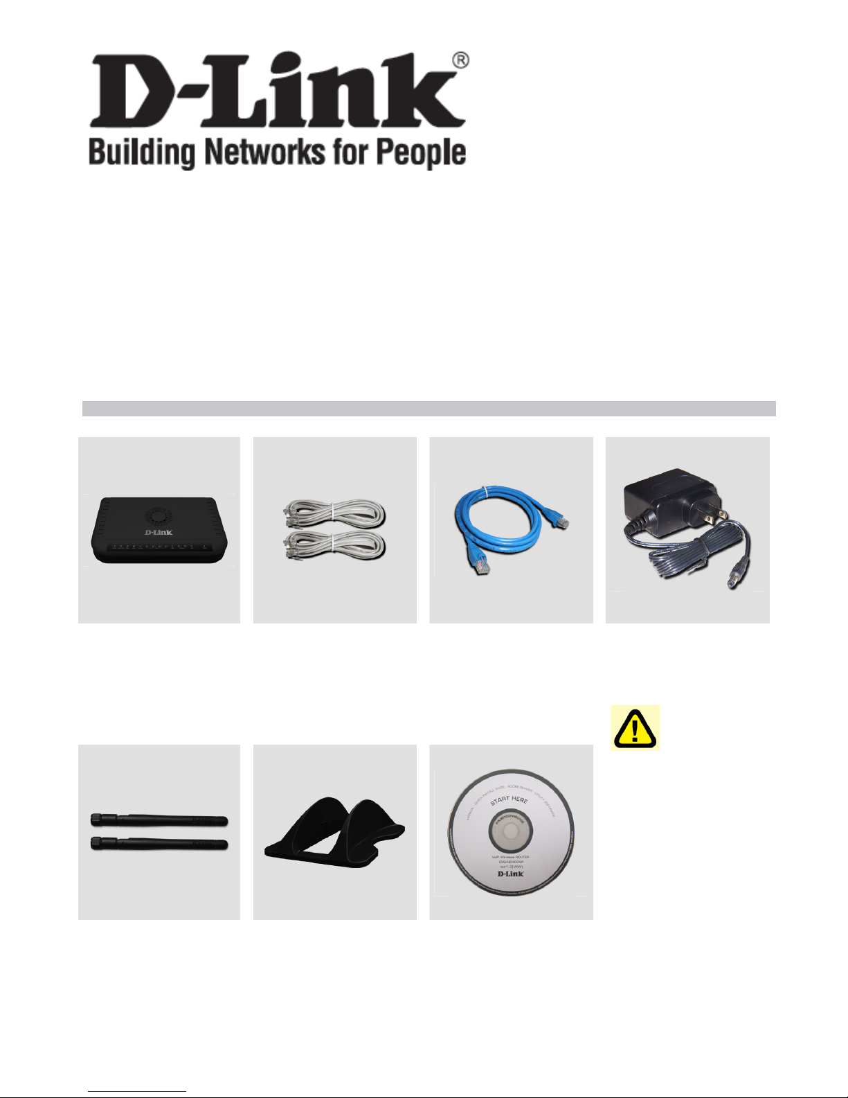
Check Your Package Contents
DVG-N5412SP
VoIP Router
Phone Cord X 2 Ether Cable
(CAT5 UTP)
Antenna X 2 Stand CD-ROM
12VDC, 2A
Power Adapter
Using a
power adapter
with a different
voltage rating will
damage this
product and void
the warranty.
2
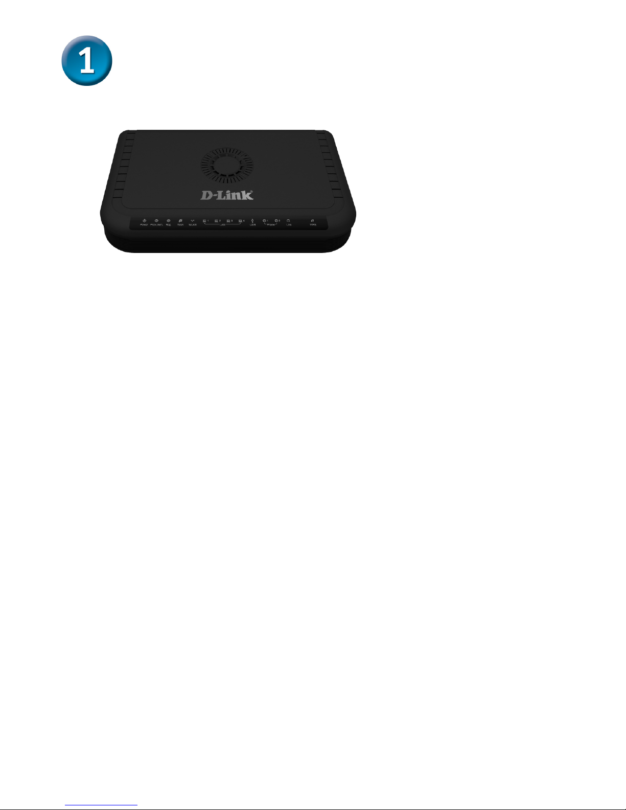
Front Panel
Power:Solid indicates a connection to a good power source.
Prov./Alm:A blinking light indicates the DVG-N5412SP can not register with SIP Server or
can not get the IP address. A blinking light also indicates the DVG-N5412SP is attempting
to connect with the Provisioning server. Once the service connects, the LED will turn off.
The LED will light solid red if the self-test or boot-up fails.
Reg.:The Register LED will turn on and continuously working when DVG-N5412SP is
connected to a VoIP service provider. The LED will flash if not connected to a service
provider.
WAN:When a connection is established the LED will light up solid. The LED will blink to
indicate activity. If the LED does not light up when a cable is connected, verify the cable
connections and make sure your devices are powered on.
WLAN:A steady light indicates a wireless connection. A blinking light indicates that DVG-
N5412SP is receiving/ transmitting from/to the wireless network
LAN:When a connection is established the LED will light up solid on the appropriate port.
The LEDs will blink to indicate activity. If the LED does not light up when a cable is
connected, verify the cable connections and make sure your devices are powered on.
USB:This indicates that DVG-N5412SP detects a supported 3G USB dungle or a USB
device.
Phone:This LED displays the VoIP status and Hook activity on the phone port that is used
to connect your normal telephone(s). If a phone connected to a phone port is off hook or in
use, this LED will light solid. When a phone is ringing, the indicator will blink.
Line:Light on means the line is in use (off-hook).
WPS: Flashing in blue as DVG-N5412SP processing WPS-PBC wireless connecting
progress.
Hardware Overview
3
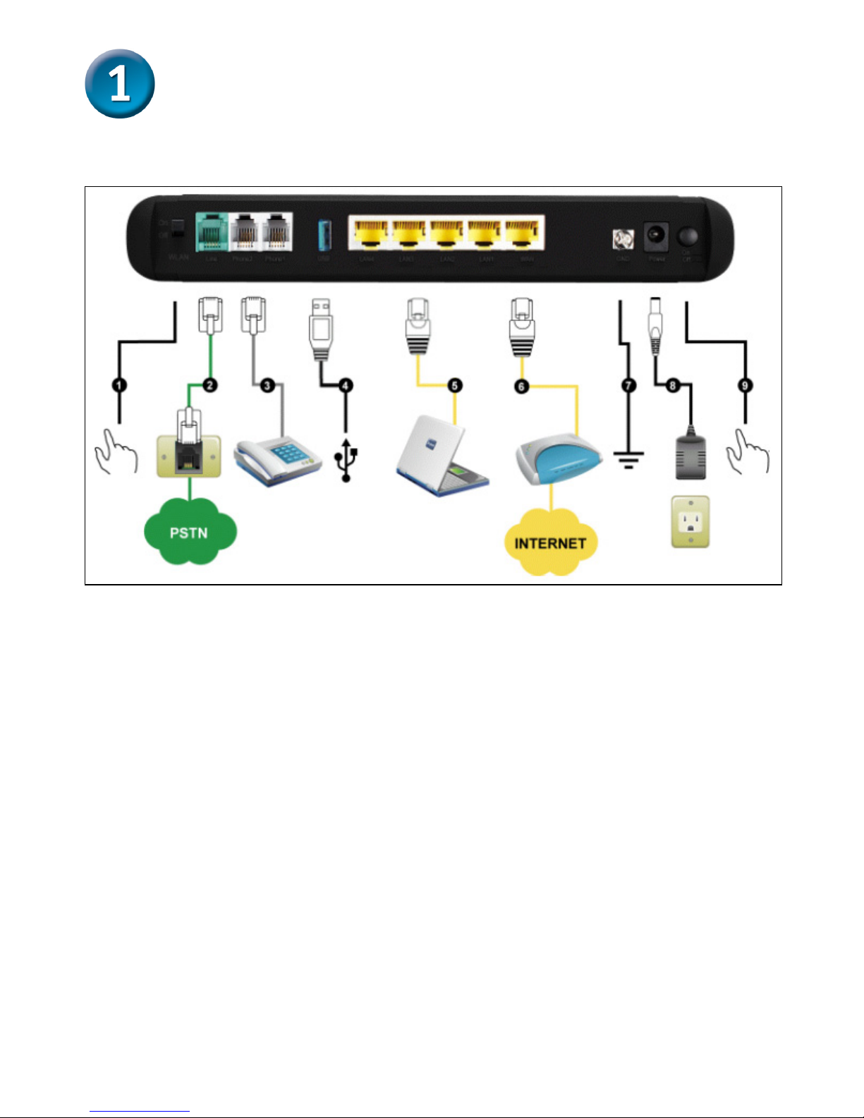
Rear Panel
1. WiFi Switch: Turn on/off wireless LAN.
2. Line: Connect to your original telephone line on the wall jack with
RJ-11 cable.
3. Phone Port (1-2): Connect to your phones using standard phone
cabling (RJ-11).
4. USB: Connect to a 3G USB dungle or a printer.
5. LAN: Connect to your Ethernet enabled computers using Ethernet
cabling.
6. WAN: Connect to your broadband modem using an Ethernet cable.
7. Ground: A conducting connection with the earth. Connect with the
ground so as to make the earth a part of an electrical circuit using
metal wire.
8. Power Receptor: Receptor for the provided power adapter.
9. Power Switch: Press down to turn-on DVG-N5412SP.
Hardware Overview (continued)
4
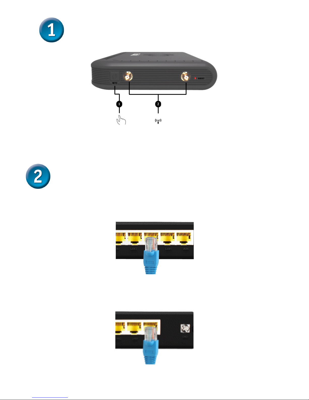
1. WPS: WPS button for wireless WPS-PBC setup method.
2. Antenna: Connect to antenna for wireless network.
A. Insert one end of the Ethernet cable into the Ethernet (LAN) port on
the back panel of the DVG-N5412SP and the other end of the cable
to an Ethernet Adapter or available Ethernet port on your computer.
B. Insert one end of the Ethernet cable into the WAN port on the back of
the DVG-N5412SP and the other into your cable/DSL modem or the
LAN port of your router.
Installing the Hardware
Hardware Overview (continued)
 Loading...