

Page 1

User Manual
DVG-N5402G/ACF
Wireless AC1200 Dual Band Gigabit Router with Fiber WAN
Port, 3G/LTE Support, 2 FXS Ports, 1 PSTN (lifeline) Port, and
USB Port
April 2017
Page 2

DVG-N5402G/ACF Wireless AC1200 Dual Band Gigabit Router
with Fiber WAN Port, 3G/LTE Support, 2 FXS Ports, 1 PSTN
(lifeline) Port, and USB Port
User Manual
Contents
Chapter 1. Introduction..........................................5
Contents and Audience.......................................................5
Conventions.................................................................5
Document Structure..........................................................5
Chapter 2. Overview..............................................6
General Information.........................................................6
Specifications*.............................................................7
Product Appearance.........................................................14
Front and Right Side Panels..............................................14
Back Panel...............................................................16
Delivery Package...........................................................18
Chapter 3. Installation and Connection..........................19
Before You Begin...........................................................19
Connecting to PC...........................................................21
PC with Ethernet Adapter.................................................21
Obtaining IP Address Automatically in OS Windows XP......................22
Obtaining IP Address Automatically in OS Windows 7.......................25
PC with Wi-Fi Adapter....................................................30
Configuring Wi-Fi Adapter in OS Windows XP...............................31
Configuring Wi-Fi Adapter in OS Windows 7................................32
Connecting to Web-based Interface..........................................34
Web-based Interface Structure..............................................36
General Information Page.................................................36
Menu Sections............................................................38
Notifications and System Drop-down Menu..................................40
Chapter 4. Configuring via Web-based Interface..................43
Monitoring.................................................................43
Click'n'Connect............................................................47
Creating WAN Connection..................................................50
PPPoE Connection.......................................................50
IPv6 PPPoE or PPPoE Dual Stack Connection..............................51
Static IP Connection...................................................52
Dynamic IP Connection..................................................53
Static IPv6 Connection.................................................54
Dynamic IPv6 Connection................................................55
PPPoE + Static IP Connection...........................................56
PPPoE + Dynamic IP Connection..........................................58
PPTP + Static IP or L2TP + Static IP Connection........................60
PPTP + Dynamic IP or L2TP + Dynamic IP Connection......................62
3G Connection..........................................................64
LTE Connection.........................................................65
Checking Internet Availability...........................................66
Configuring Wireless Connection..........................................67
Configuring IPTV.........................................................73
Wireless Network Settings Wizard...........................................74
Access Point Mode........................................................75
Client Mode..............................................................80
Virtual Server Settings Wizard.............................................83
IPTV Settings Wizard.......................................................85
Page 2 of 259
Page 3

DVG-N5402G/ACF Wireless AC1200 Dual Band Gigabit Router
with Fiber WAN Port, 3G/LTE Support, 2 FXS Ports, 1 PSTN
(lifeline) Port, and USB Port
User Manual
Status.....................................................................86
Network Statistics.......................................................86
DHCP.....................................................................87
Routing Table............................................................88
Clients..................................................................89
Active Sessions..........................................................90
Multicast groups.........................................................91
Net........................................................................92
WAN......................................................................92
Creating PPPoE WAN Connection..........................................93
Creating IPv6 PPPoE or PPPoE Dual Stack WAN Connection.................97
Creating Static IP or Dynamic IP WAN Connection.......................103
Creating Static IPv6 or Dynamic IPv6 WAN Connection...................108
Creating PPPoE + Static IP or PPPoE + Dynamic IP WAN Connection.......112
Creating PPTP/L2TP + Static IP or PPTP/L2TP + Dynamic IP WAN Connection
......................................................................119
Creating 3G WAN Connection............................................126
Creating LTE WAN Connection...........................................129
LAN.....................................................................132
Wi-Fi.....................................................................136
Basic Settings..........................................................136
2.4GHz Band...........................................................136
5GHz Band.............................................................139
Security Settings.......................................................142
MAC Filter..............................................................148
List of Wi-Fi Clients...................................................150
WPS.....................................................................151
Using WPS Function via Web-based Interface............................154
Using WPS Function without Web-based Interface........................154
Additional Settings.....................................................156
WMM.....................................................................159
Client..................................................................161
Advanced..................................................................164
VLAN....................................................................165
UPnP IGD................................................................168
EtherWAN................................................................169
Port Settings...........................................................170
Redirect................................................................173
DDNS....................................................................174
DNS.....................................................................176
Routing.................................................................177
IPv6 Routing............................................................179
Remote Access to Device.................................................181
Miscellaneous...........................................................184
TR-069 Client...........................................................186
IPsec...................................................................188
Firewall..................................................................194
IP Filters..............................................................194
Virtual Servers.........................................................197
DMZ.....................................................................199
MAC Filter..............................................................200
Page 3 of 259
Page 4

DVG-N5402G/ACF Wireless AC1200 Dual Band Gigabit Router
with Fiber WAN Port, 3G/LTE Support, 2 FXS Ports, 1 PSTN
(lifeline) Port, and USB Port
User Manual
3G/LTE Modem..............................................................202
Settings................................................................203
Information.............................................................204
PIN.....................................................................205
USB Storage...............................................................207
Information.............................................................207
Filebrowser.............................................................208
Print Server............................................................209
Samba...................................................................210
FTP.....................................................................211
DLNA....................................................................212
Transmission..............................................................214
Transmission Settings...................................................214
Control...................................................................217
URL Filter..............................................................217
VoIP......................................................................219
Basic Settings..........................................................219
Advanced Settings.......................................................222
Audio Settings..........................................................229
Phone Book..............................................................231
Call Feature Code.......................................................233
Alarm Clock.............................................................235
Security................................................................236
System....................................................................237
Administrator Password..................................................238
Configuration...........................................................239
System Log..............................................................241
Firmware Upgrade........................................................244
Local Update..........................................................245
Remote Update.........................................................246
System Time.............................................................247
Ping....................................................................249
Traceroute..............................................................250
Telnet..................................................................251
USB Users...............................................................252
Interface Settings......................................................254
Chapter 5. Operation Guidelines................................255
Safety Rules and Conditions...............................................255
Wireless Installation Considerations......................................256
Chapter 6. Abbreviations and Acronyms..........................257
Page 4 of 259
Page 5
DVG-N5402G/ACF Wireless AC1200 Dual Band Gigabit Router
with Fiber WAN Port, 3G/LTE Support, 2 FXS Ports, 1 PSTN
(lifeline) Port, and USB Port
User Manual
Introduction
CHAPTER 1. INTRODUCTION
Contents and Audience
This manual describes the router DVG-N5402G/ACF and explains how to configure and operate it.
This manual is intended for users familiar with basic networking concepts, who create an in-home
local area network, and system administrators, who install and configure networks in offices.
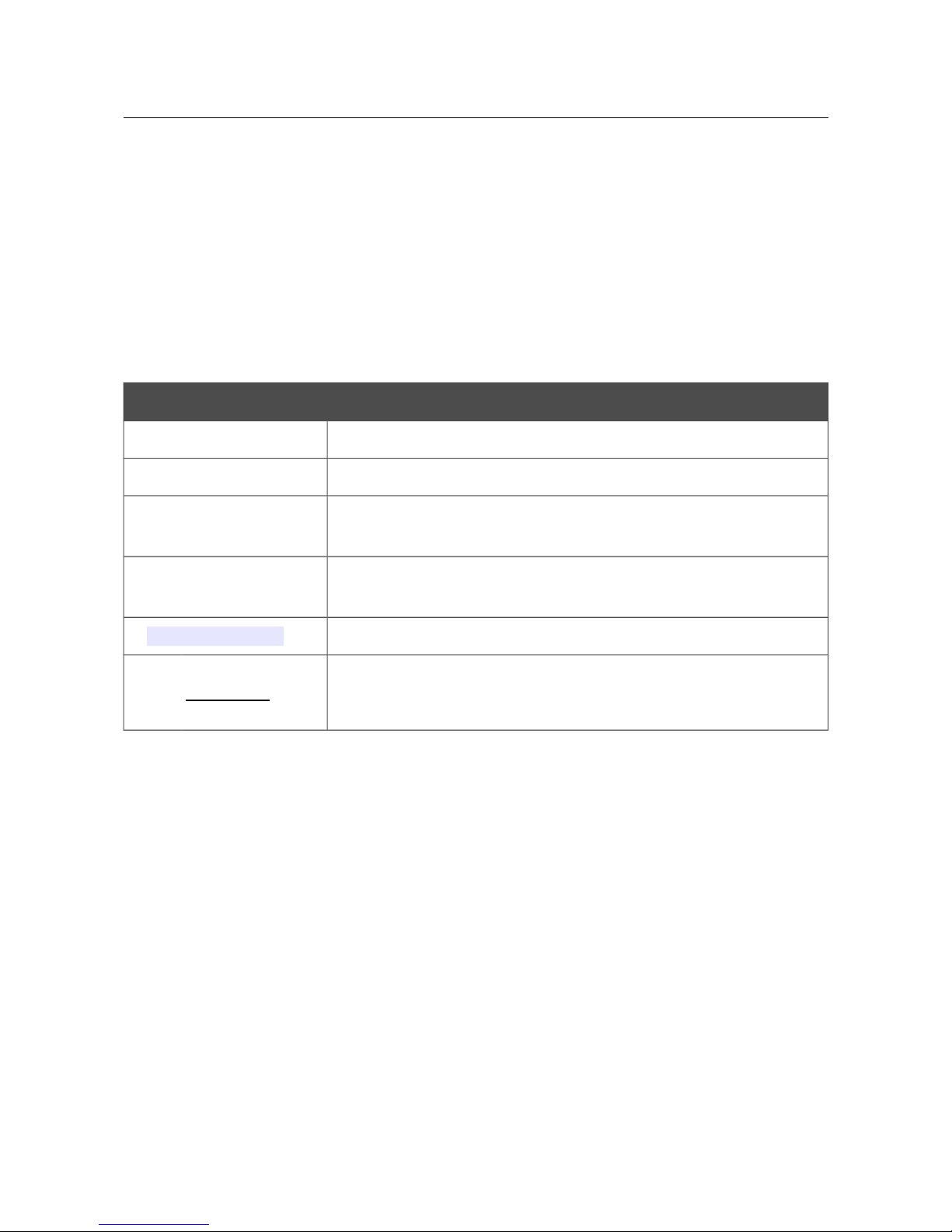
Conventions
Example Description
text The body text of the manual.
Before You Begin A reference to a chapter or section of this manual.
“Quick Installation
Guide”
A reference to a document.
Change
A name of a menu, menu item, control (field, checkbox, drop-down
list, button, etc.).
192.168.8.254
Data that you should enter in the specified field.
!
Information An important note.
Document Structure
Chapter 1 describes the purpose and structure of the document.
Chapter 2 gives an overview of the router's hardware and software features, describes its
appearance and the package contents.
Chapter 3 explains how to install the router DVG-N5402G/ACF and configure a PC in order to
access its web-based interface.
Chapter 4 describes all pages of the web-based interface in detail.
Chapter 5 includes safety instructions and tips for networking.
Chapter 6 introduces abbreviations and acronyms used in this manual.
Page 5 of 259
Page 6

DVG-N5402G/ACF Wireless AC1200 Dual Band Gigabit Router
with Fiber WAN Port, 3G/LTE Support, 2 FXS Ports, 1 PSTN
(lifeline) Port, and USB Port
User Manual
Overview
CHAPTER 2. OVERVIEW
General Information
The DVG-N5402G/ACF device is a wireless dual band gigabit VoIP router with fiber WAN port,
3G/LTE support, two FXS ports, PSTN (lifeline) port, USB port, and built-in 4-port switch.
The router is equipped with a USB port for connecting a USB modem1, which can be used to
establish connection to the Internet. In addition, to the USB port of the router you can connect a
USB storage device, which will be used as a network drive, or a printer.
Also you are able to connect the wireless router DVG-N5402G/ACF to a fiber optic line via the
fiber WAN port of the device and use a high-speed Internet connection to successfully fulfill a wide
range of professional tasks. The built-in 4-port switch enables you to connect Ethernet-enabled
computers, game consoles, and other devices to your network. In addition, any Ethernet port of the
device can be configured to connect to a private Ethernet line.
Using the DVG-N5402G/ACF device, you are able to quickly create a high-speed wireless network
at home or in your office, which lets computers and mobile devices access the Internet virtually
anywhere (within the operational range of your wireless network). Simultaneous activity of 2.4GHz
band and 5GHz band allows performing a wide range of tasks. The router can operate as a base
station for connecting wireless devices of the standards 802.11a, 802.11b, 802.11g, 802.11n, and
802.11ac (at the wireless connection rate up to 1167Mbps2).
The router supports multiple functions for the wireless interface: several security standards (WEP,
WPA/WPA2), MAC address filtering, WPS, WMM.
In addition, the device is equipped with a button for switching the Wi-Fi network off/on. If needed,
for example, when you leave home, you can easily switch the router’s WLAN by pressing the
button, and devices connected to the LAN ports of the router will stay online.
Support of guest Wi-Fi network allows you to create a separate wireless network with individual
security settings and maximum rate limitation. Devices connected to the guest network will be able
to access the Internet, but will be isolated from the devices and resources of the router's LAN.
The wireless router DVG-N5402G/ACF includes a built-in firewall. The advanced security
functions minimize threats of hacker attacks, prevent unwanted intrusions to your network, and
block access to unwanted websites for users of your LAN.
You can configure the settings of the wireless router DVG-N5402G/ACF via the user-friendly webbased interface (the interface is available in several languages).
You can simply update the firmware: the router itself finds approved firmware on D-Link update
server and notifies when ready to install it.
1 Not included in the delivery package. D-Link does not guarantee compatibility with all USB modems. For the list of
supported USB modems, see the Specifications* section, page 7.
2 Up to 300Mbps for 2.4GHz and up to 867Mbps for 5GHz.
Page 6 of 259
Page 7
DVG-N5402G/ACF Wireless AC1200 Dual Band Gigabit Router
with Fiber WAN Port, 3G/LTE Support, 2 FXS Ports, 1 PSTN
(lifeline) Port, and USB Port
User Manual
Overview
Specifications
*
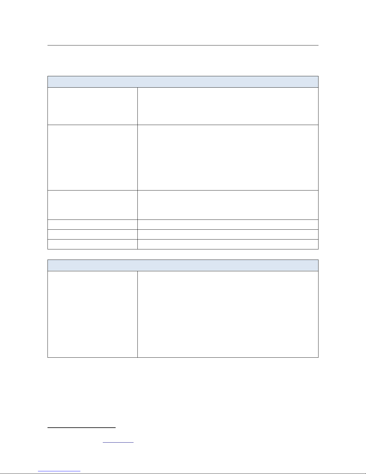
Hardware
Interfaces
· 1000BASE-X SFP WAN port
· 4 10/100/1000BASE-T LAN ports
· 2 RJ-11 FXS ports
· 1 RJ-11 PSTN (lifeline) port
· USB 2.0 port
LEDs
· POWER
· 2.4GHz
· 5GHz
· SFP
· 4 LAN LEDs
· USB
· LINE
· 2 PHONE LEDs
· WPS
Buttons
· ON/OFF button to power on/power off
· RESET button to restore factory default settings
· WPS button to set up secure wireless connection and enable/disable wireless
network
Antenna
· Two external non-detachable antennas (5dBi gain for 2.4GHz and 5GHz)
MIMO
· 2 x 2
Power connector
· Power input connector (DC)
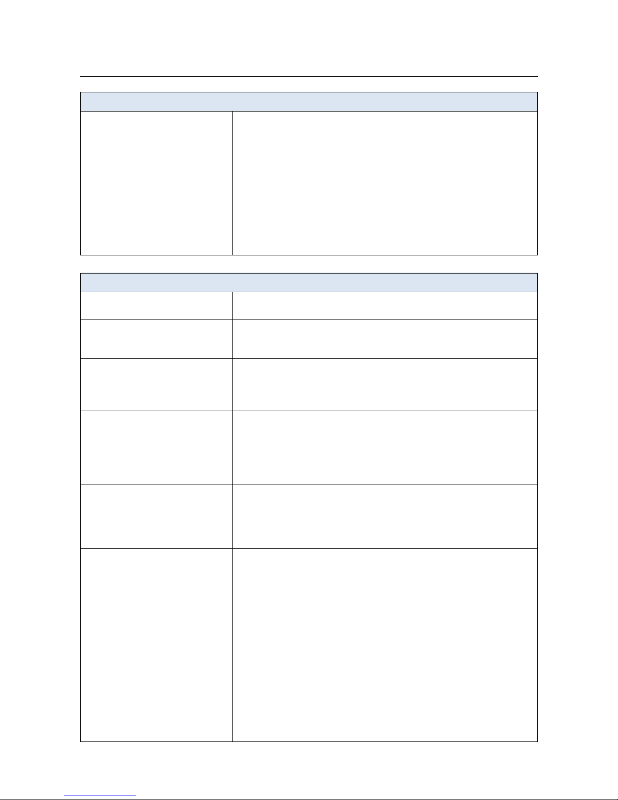
Phone
General SIP Features
· Individual account per port
· Invite with Challenge
· Register by IP address or domain name of SIP server
· Backup proxy support
· Support of DHCP option 120
· RFC3986 SIP URI format support
· Outbound proxy support
· STUN client
· NAT keep-alive
· Call types: voice/modem/fax
· User programmable Dial Plan
· Manual peer table (P2P)
* The device features are subject to change without notice. For the latest versions of the firmware and relevant
documentation, visit www.dlink.ru.
Page 7 of 259
Page 8

DVG-N5402G/ACF Wireless AC1200 Dual Band Gigabit Router
with Fiber WAN Port, 3G/LTE Support, 2 FXS Ports, 1 PSTN
(lifeline) Port, and USB Port
User Manual
Overview
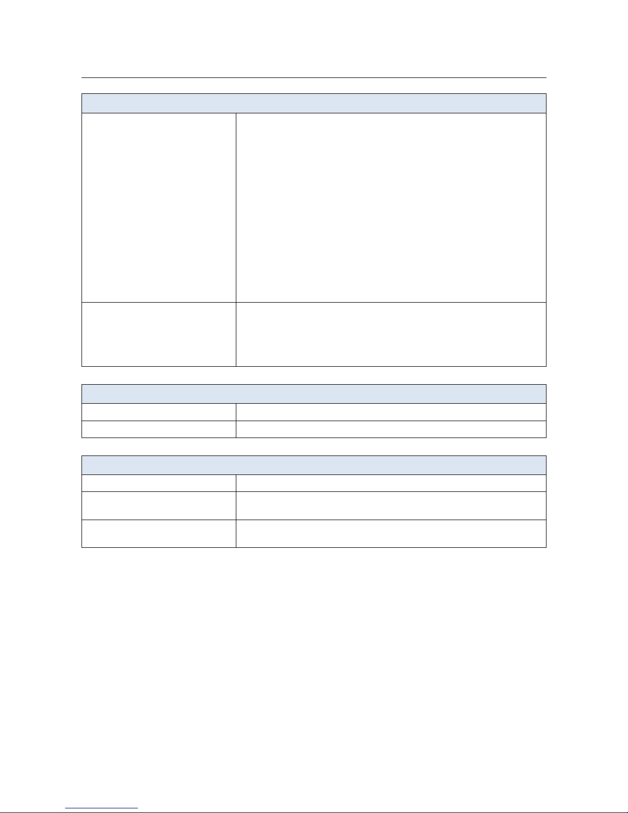
Phone
Call Features
· Direct IP-to-IP сall without SIP proxy
· Lifeline (PSTN-backup)
· PSTN call by prefix
· Call hold/retrieve
· Call awaiting
· Forwarding (unconditional, busy, no answer)
· Do Not Disturb
· Blocking hidden number calls
· Speed dialing
· Phone book
· Hotline
· Vertical service codes
· Intercom (internal calls without SIP server)
· Filtering by IP address (white/black list)
· Alarm clock
Voice Features
· Codecs: G.711 a/μ-law, G.729A, G.726, G.722, G.723.1
· DTMF detection and generation
· In-band DTMF, out-of-band DTMF (RFC2833, SIP-INFO)
· Comfort Noise Generation (CNG)
· Voice Activity Detection (VAD)
· Dynamic Jitter Buffer
· Call progress tone generation (FXS)
· DTMF/PULSE dial support
· Caller ID detection and generation
· T.30 FAX bypass to G.711, T.38 Real Time FAX Relay
· Adjustable Flash Time
· Volume control (speaker/microphone)
Software
WAN connection types
· LTE
· 3G
· PPPoE
· IPv6 PPPoE
· PPPoE Dual Stack
· Static IP / Dynamic IP
· Static IPv6 / Dynamic IPv6
· PPPoE + Static IP / Dynamic IP
· PPTP/L2TP
· PPTP/L2TP + Static IP
· PPTP/L2TP + Dynamic IP
Page 8 of 259
Page 9

DVG-N5402G/ACF Wireless AC1200 Dual Band Gigabit Router
with Fiber WAN Port, 3G/LTE Support, 2 FXS Ports, 1 PSTN
(lifeline) Port, and USB Port
User Manual
Overview
Software
Network functions
· Support of IEEE 802.1X for Internet connection
· DHCP server/relay
· DHCPv6 server (Stateful/Stateless), IPv6 prefix delegation
· DNS relay
· Support of DNSv6 AAAA records
· Dynamic DNS
· Static IP routing
· Static IPv6 routing
· IGMP Proxy
· RIP
· Support of UPnP IGD
· Support of VLAN
· WAN ping respond
· Support of SIP ALG
· Support of RTSP
· Autonegotiation of speed, duplex mode, and flow control/Manual speed and
duplex mode setup for each Ethernet port
Firewall functions
· Network Address Translation (NAT)
· Stateful Packet Inspection (SPI)
· IP filter
· IPv6 filter
· MAC filter
· URL filter
· DMZ
· Prevention of ARP and DDoS attacks
· Virtual servers
VPN
· IPSec/PPTP/L2TP/PPPoE pass-through
· IPSec tunnels
USB interface functions
· USB modem
Auto connection to available type of supported network (4G/3G/2G)
3
Auto configuration of connection upon plugging in USB modem
4
Enabling/disabling PIN code check, changing PIN code
5
· USB storage
File browser
Print server
Access to storage via accounts
Built-in Samba server
Built-in FTP server
Built-in DLNA server
Built-in Transmission torrent client; uploading/downloading files from/to USB
storage
3 For LTE and GSM USB modems.
4 For LTE and GSM USB modems.
5 For GSM USB modems and some models of LTE USB modems.
Page 9 of 259
Page 10
DVG-N5402G/ACF Wireless AC1200 Dual Band Gigabit Router
with Fiber WAN Port, 3G/LTE Support, 2 FXS Ports, 1 PSTN
(lifeline) Port, and USB Port
User Manual
Overview
Software
Management
· Local and remote access to settings through TELNET/WEB (HTTP/HTTPS)
· Multilingual web-based interface for configuration and management
· Notification on connection problems and auto redirect to settings
· Firmware update via web-based interface
· Automatic notification on new firmware version
· Saving/restoring configuration to/from file
· Support of logging to remote host/connected USB storage
· Automatic synchronization of system time with NTP server and manual
time/date setup
· Ping utility
· Traceroute utility
· TR-069 client
Wireless Module Parameters
Standards
· IEEE 802.11a/n/ac
· IEEE 802.11b/g/n
Frequency range
· 2400 ~ 2483.5MHz
· 5150 ~ 5350MHz
· 5650 ~ 5725MHz
Wireless connection security
· WEP
· WPA/WPA2 (Personal/Enterprise)
· МАС filter
· WPS (PBC/PIN)
Advanced functions
· Support of client mode
· WMM (Wi-Fi QoS)
· Information on connected Wi-Fi clients
· Advanced settings
· Guest Wi-Fi / support of MBSSID
· Limitation of wireless network rate
Wireless connection rate
· IEEE 802.11a: 6, 9, 12, 18, 24, 36, 48, and 54Mbps
· IEEE 802.11b: 1, 2, 5.5, and 11Mbps
· IEEE 802.11g: 6, 9, 12, 18, 24, 36, 48, and 54Mbps
· IEEE 802.11n (2.4GHz/5GHz): from 6.5 to 300Mbps (from MCS0 to MCS15)
· IEEE 802.11ac (5GHz): from 6.5 to 867Mbps (from MCS0 to MSC9)
Transmitter output power
The maximum value of the transmitter
output power depends upon the radio
frequency regulations applied in your
country
· 802.11a (typical at room temperature 25 °C)
15dBm at 6, 54Mbps
· 802.11b (typical at room temperature 25 °C)
14dBm at 1, 2, 5.5, 11Mbps
· 802.11g (typical at room temperature 25 °C)
14dBm at 6, 9, 12, 18, 24, 36, 48, 54Mbps
· 802.11n (typical at room temperature 25 °C)
2.4GHz, HT20
13dBm at MCS0~15
2.4GHz, HT40
12dBm at MCS0~15
5GHz, HT20/HT40
15dBm at MCS0
15dBm at MCS7
· 802.11ac (typical at room temperature 25 °C)
VHT20/VHT40/VHT80
15dBm at MCS0
15dBm at MCS9
Page 10 of 259
Page 11

DVG-N5402G/ACF Wireless AC1200 Dual Band Gigabit Router
with Fiber WAN Port, 3G/LTE Support, 2 FXS Ports, 1 PSTN
(lifeline) Port, and USB Port
User Manual
Overview
Wireless Module Parameters
Receiver sensitivity
· 802.11a (typical at PER < 10% at room temperature 25 °C)
-87dBm at 6Mbps
-86dBm at 9Mbps
-84dBm at 12Mbps
-82dBm at 18Mbps
-79dBm at 24Mbps
-76dBm at 36Mbps
-71dBm at 48Mbps
-70dBm at 54Mbps
· 802.11b (typical at PER = 10% at room temperature 25 °C)
-84dBm at 1, 2Mbps
-82dBm at 5.5Mbps
-79dBm at 11Mbps
· 802.11g (typical at PER = 10% at room temperature 25 °C)
-82dBm at 6Mbps
-81dBm at 9Mbps
-79dBm at 12Mbps
-77dBm at 18Mbps
-74dBm at 24Mbps
-70dBm at 36Mbps
-66dBm at 48Mbps
-65dBm at 54Mbps
· 802.11n (typical at PER < 10% at room temperature 25 °C)
2.4GHz, HT20
-82dBm at MCS0/8
-79dBm at MCS1/9
-77dBm at MCS2/10
-74dBm at MCS3/11
-70dBm at MCS4/12
-66dBm at MCS5/13
-65dBm at MCS6/14
-64dBm at MCS7/15
2.4GHz, HT40
-79dBm at MCS0/8
-76dBm at MCS1/9
-74dBm at MCS2/10
-71dBm at MCS3/11
-67dBm at MCS4/12
-63dBm at MCS5/13
-62dBm at MCS6/14
-61dBm at MCS7/15
5GHz, HT20
-86dBm at MCS0/8
-83dBm at MCS1/9
-81dBm at MCS2/10
-77dBm at MCS3/11
-75dBm at MCS4/12
-70dBm at MCS5/13
-69dBm at MCS6/14
-68dBm at MCS7/15
5GHz, HT40
-83dBm at MCS0/8
-80dBm at MCS1/9
-78dBm at MCS2/10
-75dBm at MCS3/11
-72dBm at MCS4/12
-67dBm at MCS5/13
-66dBm at MCS6/14
-65dBm at MCS7/15
Page 11 of 259
Page 12
DVG-N5402G/ACF Wireless AC1200 Dual Band Gigabit Router
with Fiber WAN Port, 3G/LTE Support, 2 FXS Ports, 1 PSTN
(lifeline) Port, and USB Port
User Manual
Overview
Wireless Module Parameters
· 802.11ac (typical at PER < 10% at room temperature 25 °C)
HT20
-61dBm at MCS8
-59dBm at MCS9
HT40
-58dBm at MCS8
-56dBm at MCS9
HT80
-80dBm at MCS0
-77dBm at MCS1
-75dBm at MCS2
-71dBm at MCS3
-69dBm at MCS4
-64dBm at MCS5
-62dBm at MCS6
-61dBm at MCS7
-56dBm at MCS8
-53dBm at MCS9
Modulation schemes
· 802.11a: BPSK, QPSK, 16QAM, 64QAM with OFDM
· 802.11b: DQPSK, DBPSK, CCK
· 802.11g: BPSK, QPSK, 16QAM, 64QAM with OFDM
· 802.11n: BPSK, QPSK, 16QAM, 64QAM with OFDM
· 802.11ac: BPSK, QPSK, 16QAM, 64QAM, up to 256QAM with OFDM
Physical Parameters
Dimensions (L x W x H)
· 227 x 159 x 38 mm (8.93 x 6.26 x 1.5 in)
Weight
· 160 g (0.35 lb)
Operating Environment
Power
· Output: 12V DC, 2A
Temperature
· Operating: from 0 to 40 °C
· Storage: from -20 to 65 °C
Humidity
· Operating: from 10% to 90% (non-condensing)
· Storage: from 5% to 95% (non-condensing)
Page 12 of 259
Page 13

DVG-N5402G/ACF Wireless AC1200 Dual Band Gigabit Router
with Fiber WAN Port, 3G/LTE Support, 2 FXS Ports, 1 PSTN
(lifeline) Port, and USB Port
User Manual
Overview
Supported USB modems
6
GSM · Alcatel X500
· D-Link DWM-152C1
· D-Link DWM-156A6
· D-Link DWM-156A7
· D-Link DWM-156C1
· D-Link DWM-157B1
· D-Link DWM-157B1 (Velcom)
· D-Link DWM-158D1
· D-Link DWR-710
· Huawei E150
· Huawei E1550
· Huawei E156G
· Huawei E160G
· Huawei E169G
· Huawei E171
· Huawei E173 (Megafon)
· Huawei E220
· Huawei E352 (Megafon)
· Prolink PHS600
· ZTE MF112
· ZTE MF192
· ZTE MF626
· ZTE MF627
· ZTE MF652
· ZTE MF667
· ZTE MF668
· ZTE MF752
CDMA · Airplus MCD-650
· Airplus MCD-800
· AnyDATA ADU-300A
· AnyDATA ADU-500A
· AnyDATA ADU-510A
· Huawei EC306
· ZTE AC5710
· ZTE AC5730
LTE · Huawei E3131
· Huawei E3272
· Huawei E3351
· Huawei E3372
· Huawei E367
· Huawei E392
· Megafon M100-1
· Megafon M100-2
· Megafon M100-3
· Megafon M100-4
· Megafon M150-1
· Megafon M150-2
· Quanta 1K6E (Beeline 1K6E)
· MTS 824F
· MTS 827F
· Yota LU-150
· Yota WLTUBA-107
· ZTE MF823
· ZTE MF827
Smartphones in USB tethering mode · Some models of Android smartphones
6 The manufacturer does not guarantee proper operation of the router with every modification of the firmware of USB
modems.
Page 13 of 259
Page 14
DVG-N5402G/ACF Wireless AC1200 Dual Band Gigabit Router
with Fiber WAN Port, 3G/LTE Support, 2 FXS Ports, 1 PSTN
(lifeline) Port, and USB Port
User Manual
Overview
Product Appearance
Front and Right Side Panels
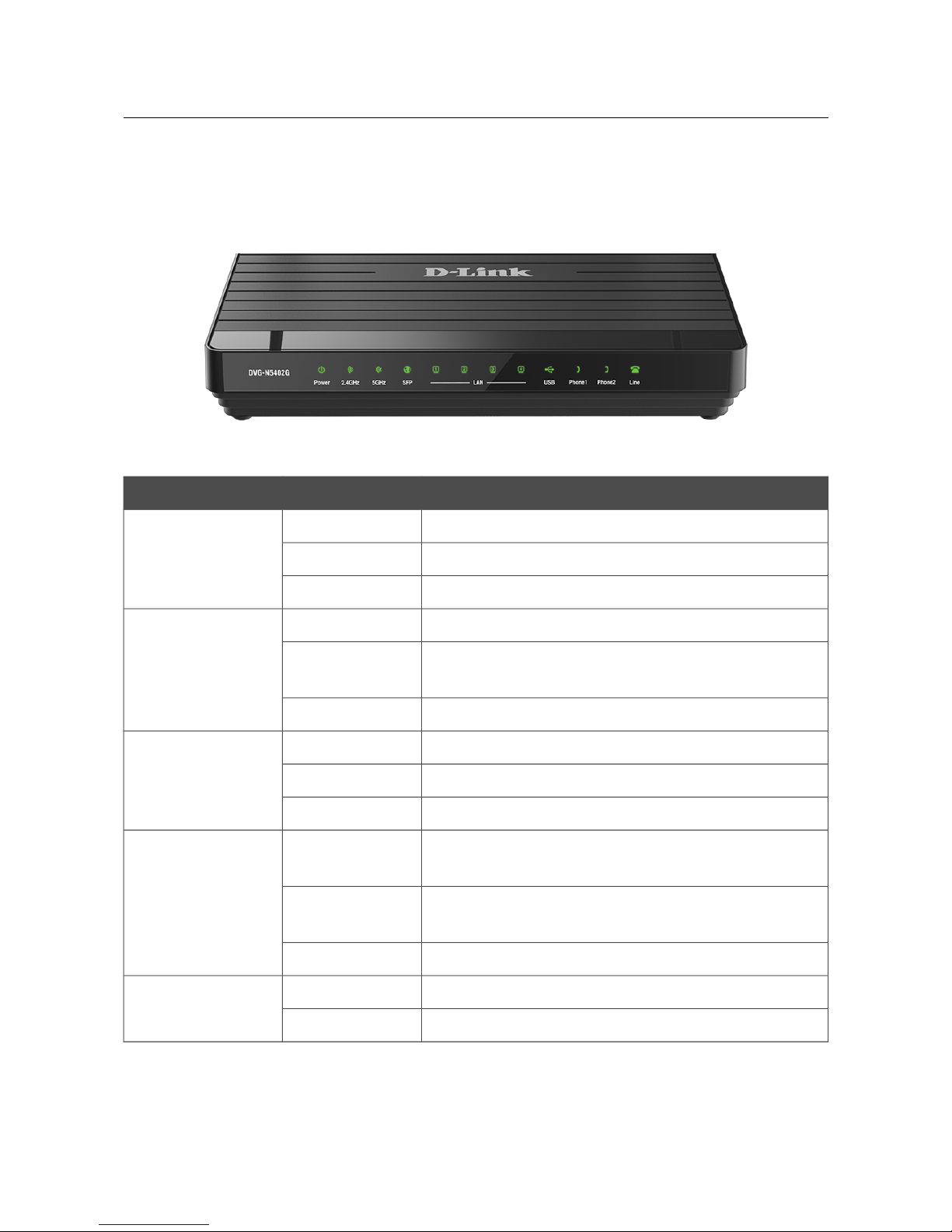
Figure 1. Front panel view.
LED Mode Description
POWER
Solid green
The router is powered on.
Blinking green
Firmware update is in progress.
No light
The router is powered off.
2.4GHz
5GHz
Solid green
The router's WLAN of the relevant band is on.
Blinking green
The WLAN interface of the relevant band is active
(upstream or downstream traffic).
No light
The router's WLAN of the relevant band is off.
SFP
Solid green
The cable is connected to the port.
Blinking green
The SFP port is active (upstream or downstream traffic).
No light
The cable is not connected.
LAN 1-4
Solid green
A device (computer) is connected to the relevant port,
the connection is on.
Blinking green
The LAN port is active (upstream or downstream
traffic).
No light
The cable is not connected to the relevant port.
USB
Solid green
A USB device is connected to the router's USB port.
No light
No USB device.
Page 14 of 259
Page 15
DVG-N5402G/ACF Wireless AC1200 Dual Band Gigabit Router
with Fiber WAN Port, 3G/LTE Support, 2 FXS Ports, 1 PSTN
(lifeline) Port, and USB Port
User Manual
Overview
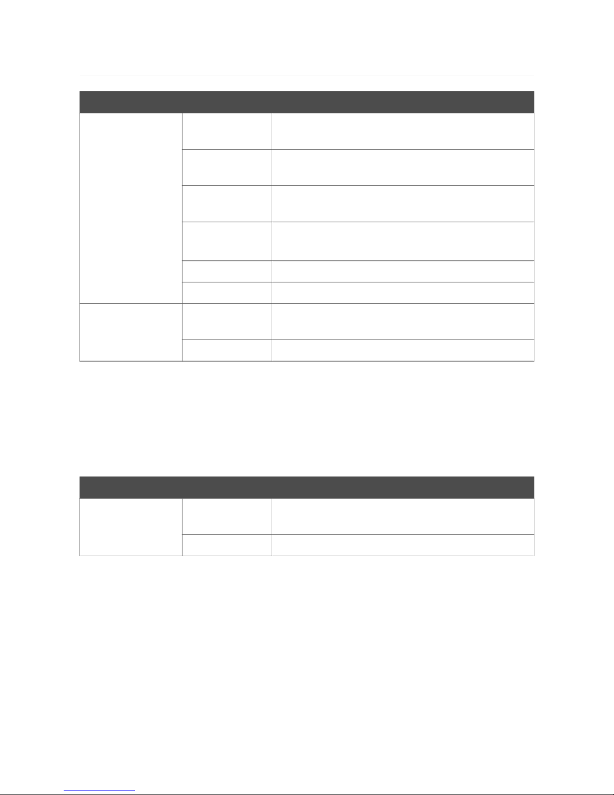
LED Mode Description
PHONE 1-2
Solid green
The receiver is on-hook, the phone is registered on the
SIP server.
Solid red
The receiver is off-hook, the phone is registered on the
SIP server.
Blinking green
The receiver is on-hook, an error occurred upon
registration on the SIP server.
Fast blinking red
If the receiver is on-hook: an incoming call.
If the receiver is off-hook: dialing or talking.
Slow blinking red
The line is busy.
No light
The phone is not registered on the SIP server.
LINE
Solid green
Activity of the PSTN port (an incoming or outgoing
call, dialing or talking).
No light
The phone line is not connected or in the idle state.
On the right side panel of the router there is a WPS button designed to set up a secure wireless
connection (the WPS function) and enable/disable the wireless network.
To use the WPS function: with the device turned on, push the button, hold it for 2 seconds, and
release. The WPS LED should be blinking blue.
To enable/disable the router's wireless network: with the device turned on, press the button, hold for
10 seconds, and then release it.
A separate LED is located on the WPS button.
LED Mode Description
WPS
Blinking blue
Attempting to add a wireless device via the WPS
function.
No light
The WPS function is not in use.
Page 15 of 259
Page 16
DVG-N5402G/ACF Wireless AC1200 Dual Band Gigabit Router
with Fiber WAN Port, 3G/LTE Support, 2 FXS Ports, 1 PSTN
(lifeline) Port, and USB Port
User Manual
Overview
Back Panel
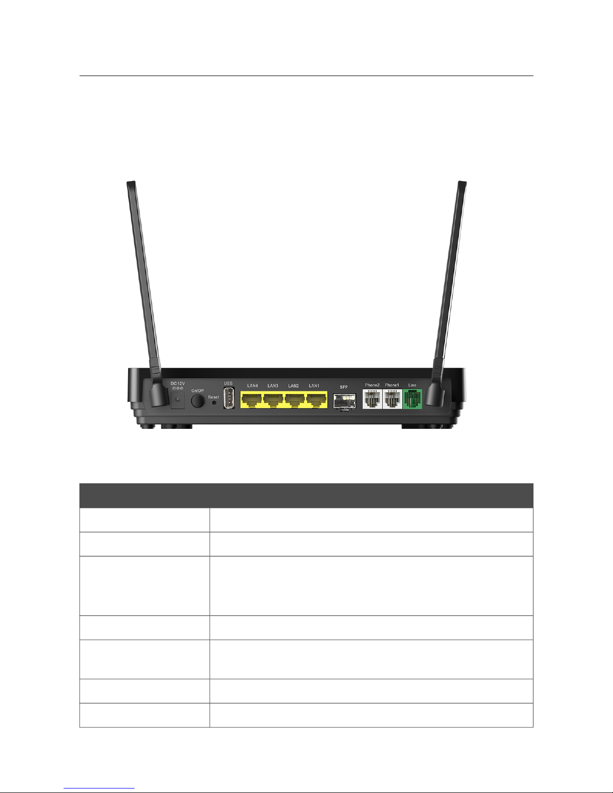
Figure 2. Back panel view.
Port Description
DC 12V
Power connector.
ON/OFF
A button to turn the router on/off.
RESET
A button to restore the factory default settings.
To restore the factory defaults, push the button (with the device turned
on), hold it for 10 seconds, and then release the button.
USB
A port for connecting a USB device (modem, storage, printer).
LAN 1-4
4 Ethernet ports to connect computers or network devices. One port
can be used to connect to a private Ethernet line.
SFP An optical port to connect to a fiber optic line.
PHONE 1-2 Ports to connect analog phones.
Page 16 of 259
Page 17

DVG-N5402G/ACF Wireless AC1200 Dual Band Gigabit Router
with Fiber WAN Port, 3G/LTE Support, 2 FXS Ports, 1 PSTN
(lifeline) Port, and USB Port
User Manual
Overview
Port Description
LINE
A PSTN port to connect to the telephone network.
The device is also equipped with two external non-detachable Wi-Fi antennas.
Page 17 of 259
Page 18

DVG-N5402G/ACF Wireless AC1200 Dual Band Gigabit Router
with Fiber WAN Port, 3G/LTE Support, 2 FXS Ports, 1 PSTN
(lifeline) Port, and USB Port
User Manual
Overview
Delivery Package
The following should be included:
• Router DVG-N5402G/ACF
• Power adapter DC 12V/2A
• Ethernet cable (CAT 5E)
• Two RJ-11 telephone cables
• “Quick Installation Guide” (brochure).
The “User Manual” and “Quick Installation Guide” documents are available on D-Link website
(see www.dlink.ru).
!
Using a power supply with a different voltage rating than the one included will cause
damage and void the warranty for this product.
Page 18 of 259
Page 19

DVG-N5402G/ACF Wireless AC1200 Dual Band Gigabit Router
with Fiber WAN Port, 3G/LTE Support, 2 FXS Ports, 1 PSTN
(lifeline) Port, and USB Port
User Manual
Installation and Connection
CHAPTER 3. INSTALLATION AND CONNECTION
Before You Begin
Please, read this manual prior to installing the device. Make sure that you have all the necessary
information and equipment.
Operating System
Configuration of the wireless dual band gigabit VoIP router DVG-N5402G/ACF (hereinafter
referred to as “the router”) is performed via the built-in web-based interface. The web-based
interface is available from any operating system that supports a web browser.
Web Browser
The following web browsers are recommended:
• Apple Safari 5 and later
• Google Chrome 10 and later
• Microsoft Internet Explorer 9 and later
• Microsoft Edge 20.10240 and later
• Mozilla Firefox 10 and later
• Opera 10 and later.
For successful operation, JavaScript should be enabled on the web browser. Make sure that
JavaScript has not been disabled by other software (such as virus protection or web user security
packages) running on your computer.
Wired or Wireless NIC (Ethernet or Wi-Fi Adapter)
Any computer that uses the router should be equipped with an Ethernet or Wi-Fi adapter (NIC). If
your computer is not equipped with such a device, install an Ethernet or Wi-Fi adapter prior to using
the router.
Wireless Connection
Wireless workstations from your network should be equipped with a wireless 802.11a, b, g, n, or ac
NIC (Wi-Fi adapter). In addition, you should specify the values of SSID, channel number and
security settings defined in the web-based interface of the router for all these wireless workstations.
SFP Transceiver
To connect to a fiber optic line, you need to use an SFP transceiver recommended by your ISP.
VoIP
On order to use VoIP over SIP, you need to connect an analog phone to the FXS port of the router.
Then access the web-based interface of the router, and you will be able to configure all needed
settings.
Page 19 of 259
Page 20

DVG-N5402G/ACF Wireless AC1200 Dual Band Gigabit Router
with Fiber WAN Port, 3G/LTE Support, 2 FXS Ports, 1 PSTN
(lifeline) Port, and USB Port
User Manual
Installation and Connection
USB Modem
To connect to an LTE, 3G GSM or CDMA network, you should use a USB modem. Connect it to
the USB port of the router, then access the web-based interface of the router, and you will be able to
configure a connection to the Internet7.
!
Your USB modem should be equipped with an active identification card (SIM or R-UIM)
of your operator.
Some operators require subscribers to activate their USB modems prior to using them.
Please, refer to connection guidelines provided by your operator when concluding the
agreement or placed on its website.
For LTE and CDMA USB modems, it is required to disable the PIN code check on the
identification card prior to connecting the USB modem to the router.
7 Contact your operator to get information on the service coverage and fees.
Page 20 of 259
Page 21

DVG-N5402G/ACF Wireless AC1200 Dual Band Gigabit Router
with Fiber WAN Port, 3G/LTE Support, 2 FXS Ports, 1 PSTN
(lifeline) Port, and USB Port
User Manual
Installation and Connection
Connecting to PC
PC with Ethernet Adapter
1. Make sure that your PC is powered off.
2. Connect an Ethernet cable between any of LAN ports located on the back panel of the router
and the Ethernet port of your PC.
3. To connect via USB modem: connect your USB modem to the USB port8 located on the
back panel of the router.
!
If you need to connect or change a USB modem to another one when the router is powered
on, power off the router, connect the modem to the USB port, and power on the router.
4. To connect the device to a fiber optic line: connect your SFP transceiver to the SFP port,
then connect the fiber optic cable to the SFP transceiver.
5. To connect the device to an Ethernet line: in the web-based interface of the router, select
the router's LAN port that will be used as the WAN port and create an Ethernet WAN
connection. Then connect an Ethernet cable between an available Ethernet port of the router
and the Ethernet line.
!
Please connect the router to the ISP's Ethernet line only after setting the WAN port and
creating the Internet connection.
6. Connect the power cord to the power connector port on the back panel of the router, then
plug the power adapter into an electrical outlet or power strip.
7. Turn on the router by pressing the ON/OFF button on its back panel.
8. Turn on your PC and wait until your operating system is completely loaded.
8 It is recommended to use a USB extension cable to connect a USB modem to the router.
Page 21 of 259
Page 22
DVG-N5402G/ACF Wireless AC1200 Dual Band Gigabit Router
with Fiber WAN Port, 3G/LTE Support, 2 FXS Ports, 1 PSTN
(lifeline) Port, and USB Port
User Manual
Installation and Connection
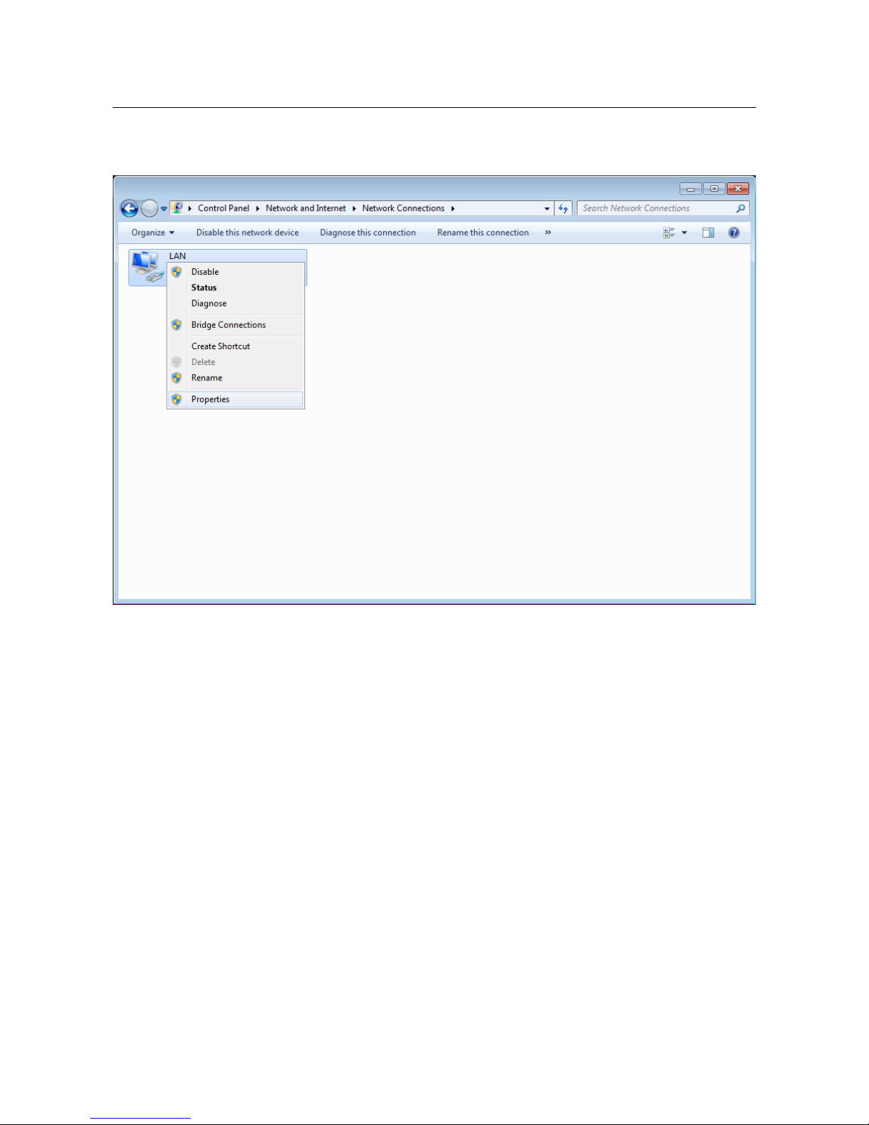
Obtaining IP Address Automatically in OS Windows XP
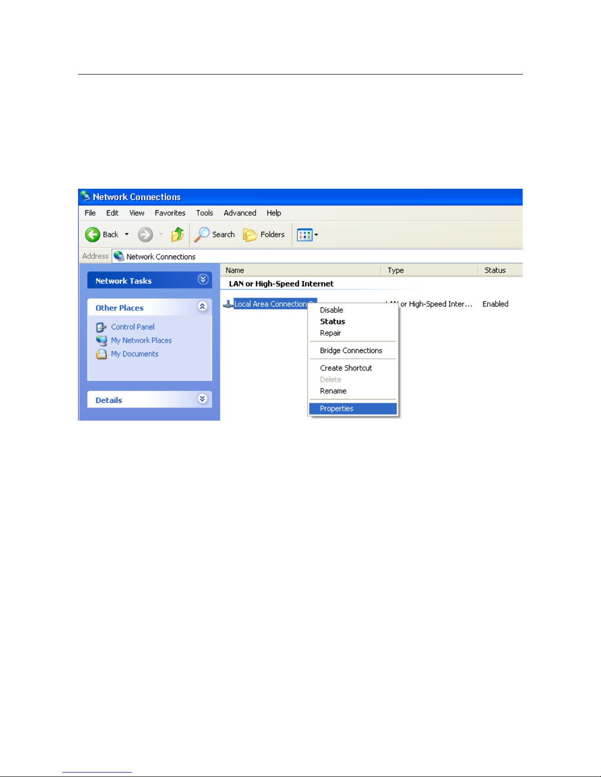
1. Click the Start button and proceed to the Control Panel > Network and Internet
Connections > Network Connections window.
2. In the Network Connections window, right-click the relevant Local Area Connection
icon and select the Properties line in the menu displayed.
Figure 3. The Network Connections window.
Page 22 of 259
Page 23
DVG-N5402G/ACF Wireless AC1200 Dual Band Gigabit Router
with Fiber WAN Port, 3G/LTE Support, 2 FXS Ports, 1 PSTN
(lifeline) Port, and USB Port
User Manual
Installation and Connection
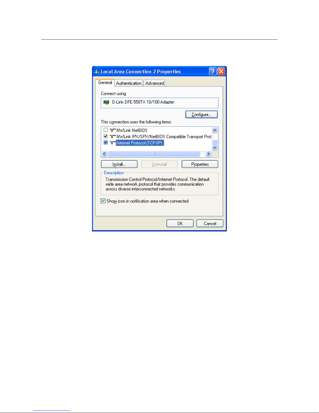
3. In the Local Area Connection Properties window, on the General tab, select the
Internet Protocol (TCP/IP) line. Click the Properties button.
Figure 4. The Local Area Connection Properties window.
Page 23 of 259
Page 24
DVG-N5402G/ACF Wireless AC1200 Dual Band Gigabit Router
with Fiber WAN Port, 3G/LTE Support, 2 FXS Ports, 1 PSTN
(lifeline) Port, and USB Port
User Manual
Installation and Connection
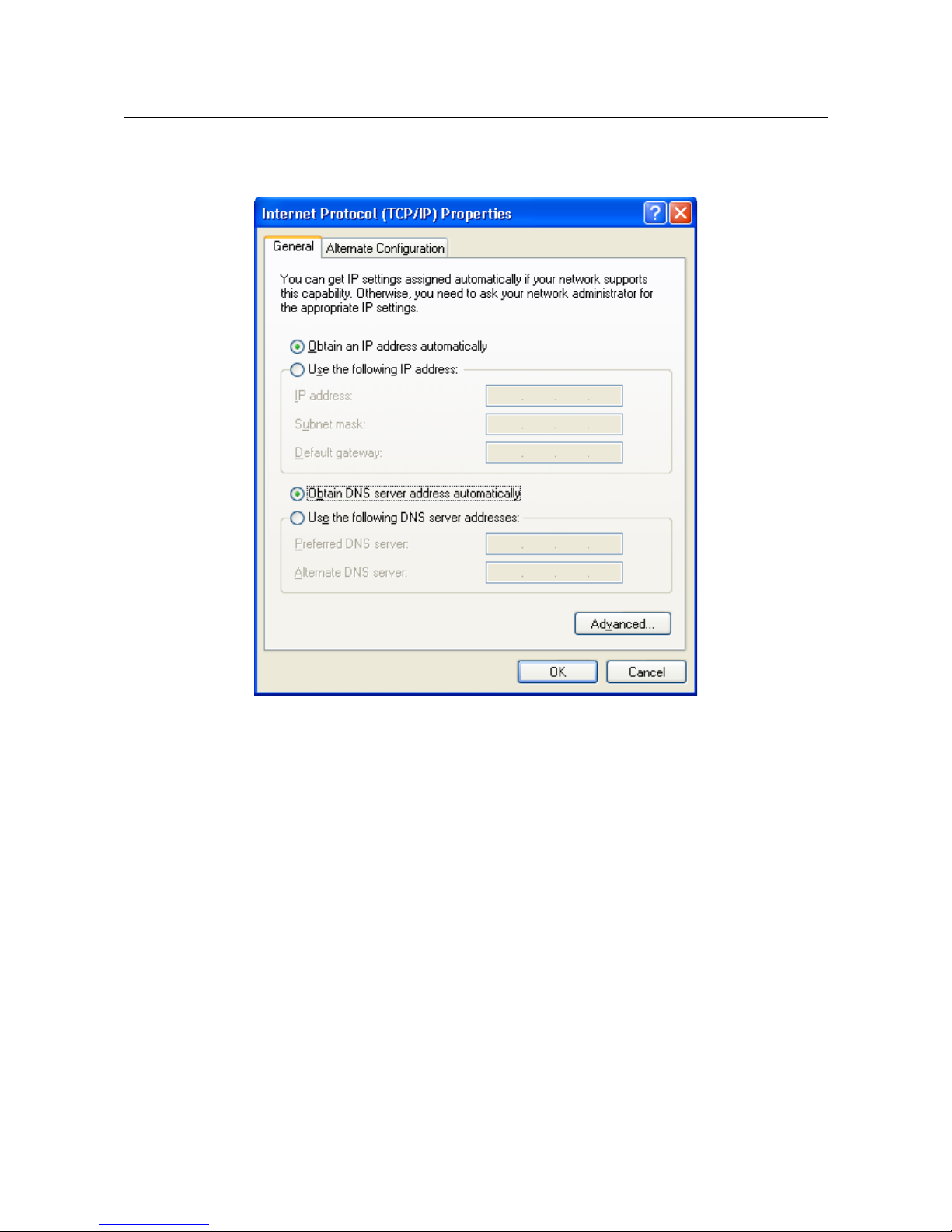
4. Select the Obtain an IP address automatically and Obtain DNS server address
automatically radio buttons. Click the OK button.
Figure 5. The Internet Protocol (TCP/IP) Properties window.
5. Click the ОК button in the connection properties window.
Now your computer is configured to obtain an IP address automatically.
Page 24 of 259
Page 25
DVG-N5402G/ACF Wireless AC1200 Dual Band Gigabit Router
with Fiber WAN Port, 3G/LTE Support, 2 FXS Ports, 1 PSTN
(lifeline) Port, and USB Port
User Manual
Installation and Connection
Obtaining IP Address Automatically in OS Windows 7
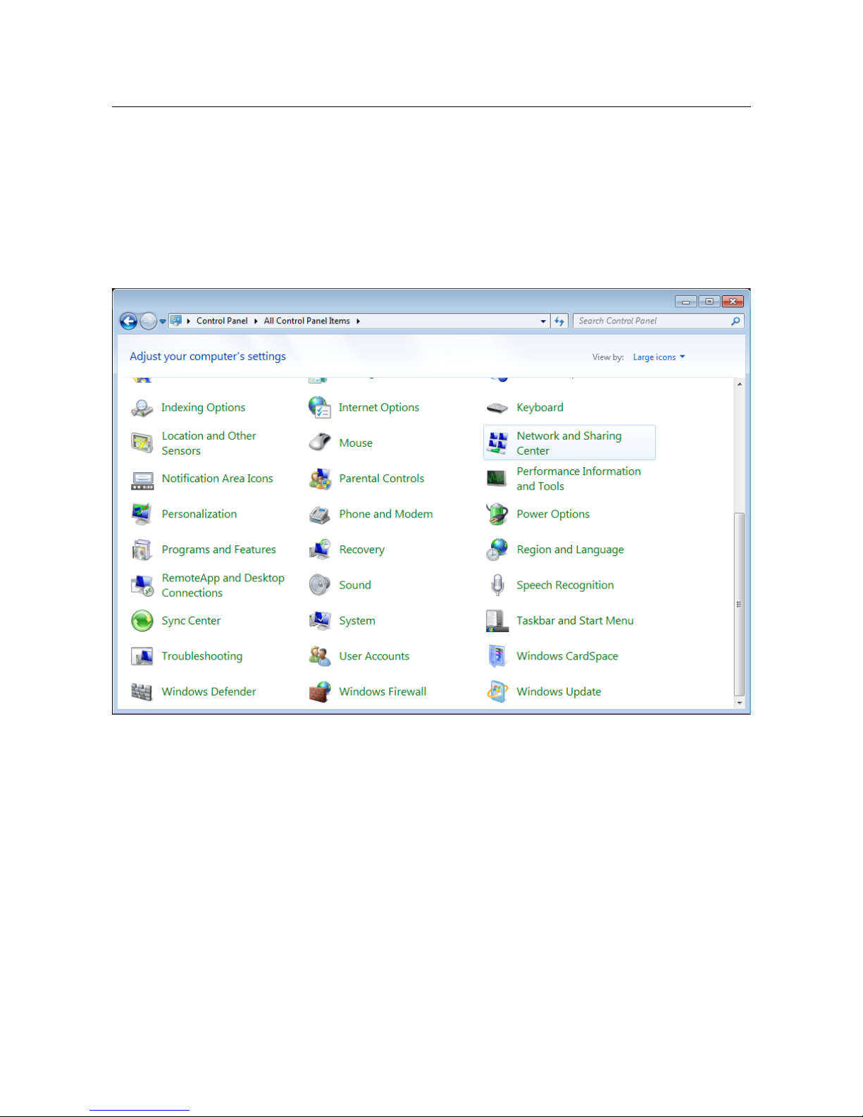
1. Click the Start button and proceed to the Control Panel window.
2. Select the Network and Sharing Center section. (If the Control Panel has the category
view (the Category value is selected from the View by drop-down list in the top right
corner of the window), choose the View network status and tasks line under the
Network and Internet section.)
Figure 6. The Control Panel window.
Page 25 of 259
Page 26
DVG-N5402G/ACF Wireless AC1200 Dual Band Gigabit Router
with Fiber WAN Port, 3G/LTE Support, 2 FXS Ports, 1 PSTN
(lifeline) Port, and USB Port
User Manual
Installation and Connection
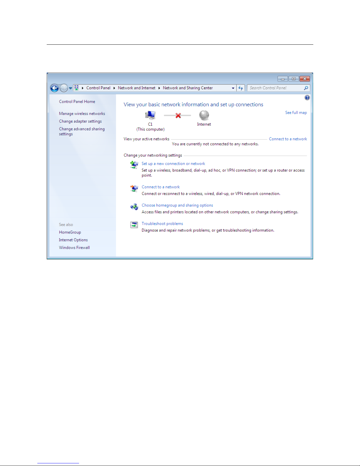
3. In the menu located on the left part of the window, select the Change adapter settings
line.
Figure 7. The Network and Sharing Center window.
Page 26 of 259
Page 27
DVG-N5402G/ACF Wireless AC1200 Dual Band Gigabit Router
with Fiber WAN Port, 3G/LTE Support, 2 FXS Ports, 1 PSTN
(lifeline) Port, and USB Port
User Manual
Installation and Connection
4. In the opened window, right-click the relevant Local Area Connection icon and select
the Properties line in the menu displayed.
Figure 8. The Network Connections window.
Page 27 of 259
Page 28
DVG-N5402G/ACF Wireless AC1200 Dual Band Gigabit Router
with Fiber WAN Port, 3G/LTE Support, 2 FXS Ports, 1 PSTN
(lifeline) Port, and USB Port
User Manual
Installation and Connection
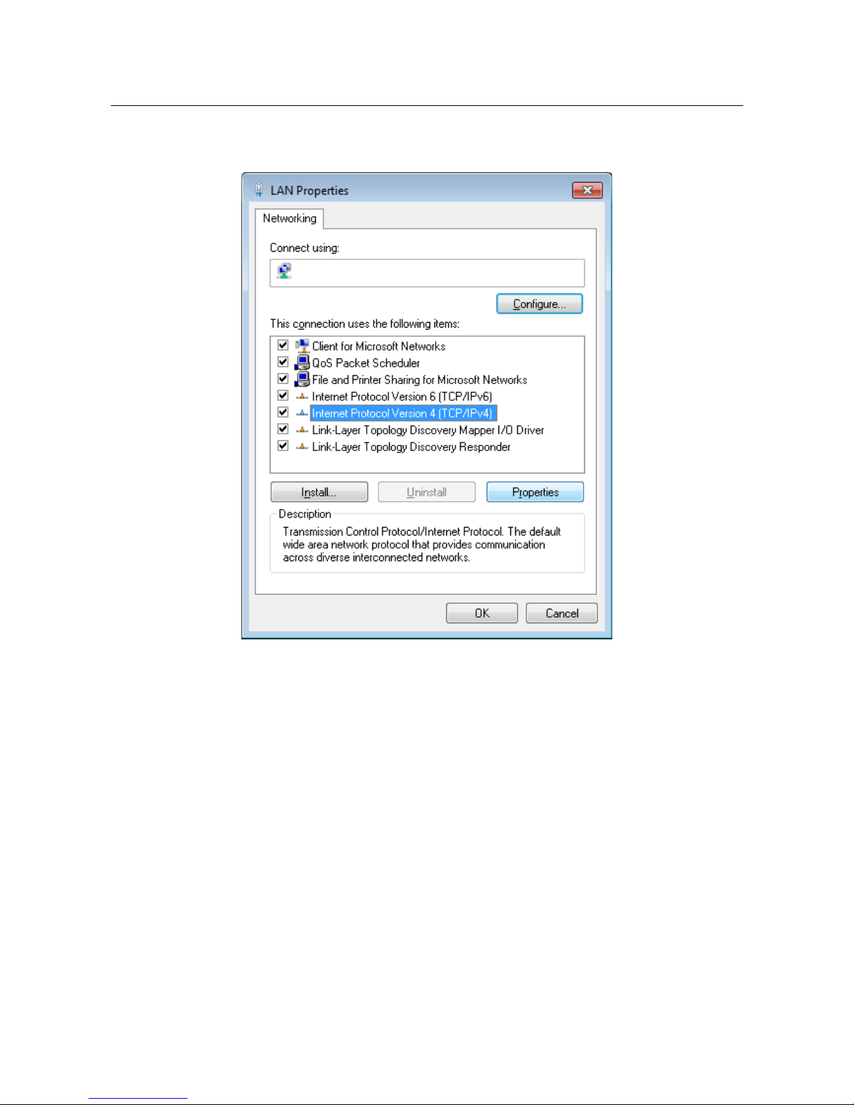
5. In the Local Area Connection Properties window, on the Networking tab, select the
Internet Protocol Version 4 (TCP/IPv4) line. Click the Properties button.
Figure 9. The Local Area Connection Properties window.
Page 28 of 259
Page 29
DVG-N5402G/ACF Wireless AC1200 Dual Band Gigabit Router
with Fiber WAN Port, 3G/LTE Support, 2 FXS Ports, 1 PSTN
(lifeline) Port, and USB Port
User Manual
Installation and Connection
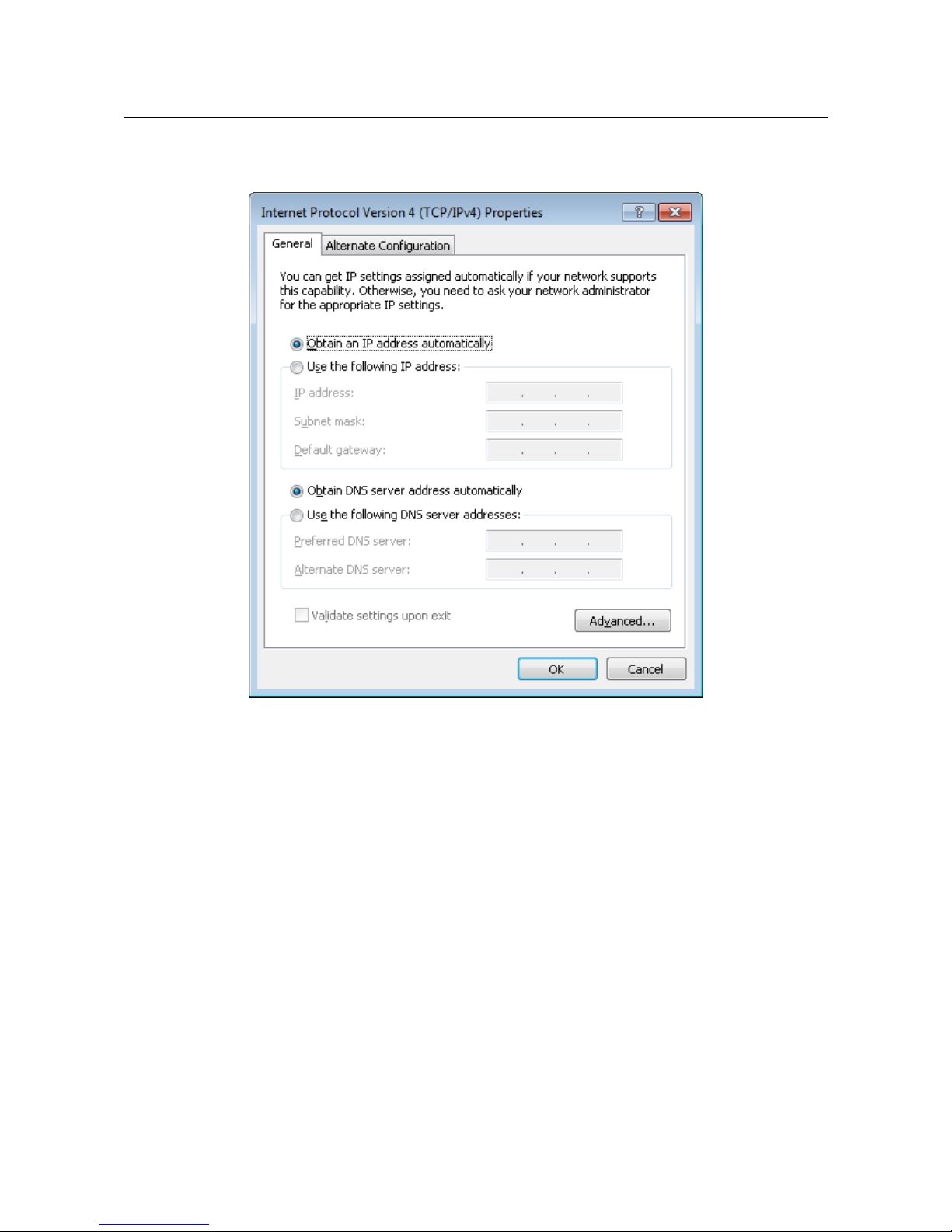
6. Select the Obtain an IP address automatically and Obtain DNS server address
automatically radio buttons. Click the OK button.
Figure 10. The Internet Protocol Version 4 (TCP/IPv4) Properties window.
7. Click the OK button in the connection properties window.
Now your computer is configured to obtain an IP address automatically.
Page 29 of 259
Page 30

DVG-N5402G/ACF Wireless AC1200 Dual Band Gigabit Router
with Fiber WAN Port, 3G/LTE Support, 2 FXS Ports, 1 PSTN
(lifeline) Port, and USB Port
User Manual
Installation and Connection
PC with Wi-Fi Adapter
1. To connect via USB modem: connect your USB modem to the USB port9 located on the
back panel of the router.
!
If you need to connect or change a USB modem to another one when the router is powered
on, power off the device, connect the modem to the USB port, and power on the router.
2. To connect the device to a fiber optic line: connect your SFP transceiver to the SFP port,
then connect the fiber optic cable to the SFP transceiver.
3. To connect the device to an Ethernet line: in the web-based interface of the router, select
the router's LAN port that will be used as the WAN port and create an Ethernet WAN
connection. Then connect an Ethernet cable between an available Ethernet port of the router
and the Ethernet line.
!
Please connect the router to the ISP's Ethernet line only after setting the WAN port and
creating the Internet connection.
4. Connect the power cord to the power connector port on the back panel of the router, then
plug the power adapter into an electrical outlet or power strip.
5. Turn on the router by pressing the ON/OFF button on its back panel.
6. Turn on your PC and wait until your operating system is completely loaded.
7. Turn on your Wi-Fi adapter. As a rule, modern notebooks with built-in wireless NICs are
equipped with a button or switch that turns on/off the wireless adapter (refer to your PC
documents). If your PC is equipped with a pluggable wireless NIC, install the software
provided with your Wi-Fi adapter.
9 It is recommended to use a USB extension cable to connect a USB modem to the router.
Page 30 of 259
Page 31

DVG-N5402G/ACF Wireless AC1200 Dual Band Gigabit Router
with Fiber WAN Port, 3G/LTE Support, 2 FXS Ports, 1 PSTN
(lifeline) Port, and USB Port
User Manual
Installation and Connection
Con$guring Wi-Fi Adapter in OS Windows XP
1. Click the Start button and proceed to the Control Panel > Network and Internet
Connections > Network Connections window.
2. Select the icon of the wireless network connection and make sure that your Wi-Fi adapter is
on.
Figure 11. The Network Connections window.
3. Search for available wireless networks.
4. In the opened Wireless Network Connection window, select the wireless network DVG-
N5402G (for operating in the 2.4GHz band) or DVG-N5402G-5G (for operating in the
5GHz band) and click the Connect button.
5. In the opened window, enter the network key (see WPS PIN on the barcode label on the
bottom panel of the device) in the Network key and Confirm network key fields and
click the Connect button.
After that the Wireless Network Connection Status window appears.
!
If you perform initial configuration of the router via Wi-Fi connection, note that
immediately after changing the wireless default settings of the router you will need to
reconfigure the wireless connection using the newly specified settings.
Page 31 of 259
Page 32

DVG-N5402G/ACF Wireless AC1200 Dual Band Gigabit Router
with Fiber WAN Port, 3G/LTE Support, 2 FXS Ports, 1 PSTN
(lifeline) Port, and USB Port
User Manual
Installation and Connection
Con$guring Wi-Fi Adapter in OS Windows 7
1. Click the Start button and proceed to the Control Panel window.
2. Select the Network and Sharing Center section. (If the Control Panel has the category
view (the Category value is selected from the View by drop-down list in the top right
corner of the window), choose the View network status and tasks line under the
Network and Internet section.)
Figure 12. The Control Panel window.
3. In the menu located on the left part of the window, select the Change adapter settings
line.
4. In the opened window, select the icon of the wireless network connection and make sure that
your Wi-Fi adapter is on.
5. To open the list of available wireless networks, select the icon of the wireless network
connection and click the Connect To button or left-click the network icon in the
notification area located on the right side of the taskbar.
Figure 13. The notification area of the taskbar.
Page 32 of 259
Page 33

DVG-N5402G/ACF Wireless AC1200 Dual Band Gigabit Router
with Fiber WAN Port, 3G/LTE Support, 2 FXS Ports, 1 PSTN
(lifeline) Port, and USB Port
User Manual
Installation and Connection
6. In the opened Wireless Network Connection window, select the wireless network DVG-
N5402G (for operating in the 2.4GHz band) or DVG-N5402G-5G (for operating in the
5GHz band) and click the Connect button.
Figure 14. The list of available networks.
7. In the opened window, enter the network key (see WPS PIN on the barcode label on the
bottom panel of the device) in the Security key field and click the OK button.
8. Wait for about 20-30 seconds. After the connection is established, the network icon will be
displayed as the signal level scale.
!
If you perform initial configuration of the router via Wi-Fi connection, note that
immediately after changing the wireless default settings of the router you will need to
reconfigure the wireless connection using the newly specified settings.
Page 33 of 259
Page 34

DVG-N5402G/ACF Wireless AC1200 Dual Band Gigabit Router
with Fiber WAN Port, 3G/LTE Support, 2 FXS Ports, 1 PSTN
(lifeline) Port, and USB Port
User Manual
Installation and Connection
Connecting to Web-based Interface
When you have configured your computer, you can access the web-based interface and configure
needed parameters (create a WAN connection, change the parameters of the wireless network,
specify the settings of the firewall, etc.).
!
Router DVG-N5402G/ACF with default settings cannot connect to the Internet. To get
started, please set your own password for access to the web-based interface and change the
WLAN name (SSID); then, if needed, configure other settings recommended by your ISP.
Start a web browser (see the Before You Begin section, page 19). In the address bar of the web
browser, enter the IP address of the router (by default, the following IP address is specified:
192.168.0.1). Press the Enter key.
Figure 15. Connecting to the web-based interface of the DVG-N5402G/ACF device.
!
If the error “ The page cannot be displayed ” (or “ Unable to display the page ”/“ Could not
connect to remote server ”) occurs upon connecting to the web-based interface of the router,
make sure that you have properly connected the router to your computer.
After the first access to the web-based interface you need to change the default administrator
password. Enter the new password in the Password and Confirmation fields. You may set any
password except admin. Use digits, Latin letters (uppercase and/or lowercase), and characters
available on the keyboard. Also you need to change the default name of the wireless network. To do
this, in the Network name (SSID) and 5GHz network name (SSID) fields, enter a new name
for the router's wireless network in the 2.4GHz and 5GHz band correspondingly or leave the values
suggested by the router: DVG-N5402G-XXXX and DVG-N5402G-5G-XXXX where XXXX are the
last 4 characters of the device's MAC address. Then click the Apply button.
Figure 16. The page for changing the default administrator password.
Page 34 of 259
Page 35

DVG-N5402G/ACF Wireless AC1200 Dual Band Gigabit Router
with Fiber WAN Port, 3G/LTE Support, 2 FXS Ports, 1 PSTN
(lifeline) Port, and USB Port
User Manual
Installation and Connection
!
Remember or write down the new password for the administrator account. In case of losing
the new password, you can access the settings of the router only after restoring the factory
default settings via the hardware RESET button. This procedure wipes out all settings that
you have configured for your router.
When the web-based interface is accessed the next time and after, the login page opens. Enter the
username (admin) in the Login field and the new password in the Password field, then click the
Enter button.
Figure 17. The login page.
Page 35 of 259
Page 36

DVG-N5402G/ACF Wireless AC1200 Dual Band Gigabit Router
with Fiber WAN Port, 3G/LTE Support, 2 FXS Ports, 1 PSTN
(lifeline) Port, and USB Port
User Manual
Installation and Connection
Web-based Interface Structure
General Information Page
After successful registration the Home / Information page opens.
Figure 18. The general information page.
Page 36 of 259
Page 37

DVG-N5402G/ACF Wireless AC1200 Dual Band Gigabit Router
with Fiber WAN Port, 3G/LTE Support, 2 FXS Ports, 1 PSTN
(lifeline) Port, and USB Port
User Manual
Installation and Connection
The web-based interface of the router is multilingual. If you need to select another language for the
web-based interface, place the mouse pointer over the English caption in the top part of the page
and select a language from the menu displayed.
Figure 19. Changing the language of the web-based interface.
The Home / Information page displays general information on the router and its software. From
the page you can quickly get to some pages of the web-based interface.
To upgrade the firmware of the router, left-click the current firmware version (the right column of
the Firmware version line) and follow the dialog box appeared.
To contact the technical support group (to send an e-mail), left-click the support e-mail address (the
right column of the Support line). After clicking the line, the e-mail client window for sending a
new letter to the specified address opens.
To edit the router's local interface parameters, left-click the IPv4, IPv6, or MAC address of the local
interface (the right column of the lines LAN IPv4, LAN IPv6 or LAN MAC correspondingly).
After clicking the line, the page for editing the LAN interface opens (for the detailed description of
the page, see the LAN section, page 132).
To configure the router's WLAN parameters, left-click the SSID of the WLAN (the right column of
the 2.4 GHz Network name (SSID) or 5 GHz Network name (SSID) line). After clicking the
line, the Wi-Fi / Basic settings page for the relevant band opens (for the detailed description of
the page, see the Basic Settings section, page 136).
To configure security settings of the WLAN, left-click the network authentication type (the right
column of the 2.4 GHz security or 5 GHz security line). After clicking the line, the Wi-Fi /
Security settings page for the relevant band opens (for the detailed description of the page, see
the Security Settings section, page 142).
In the VoIP lines status section, data on the status of registration on the SIP proxy server and the
phone status are displayed.
In the USB section, data on the USB device connected to the router is displayed.
Page 37 of 259
Page 38

DVG-N5402G/ACF Wireless AC1200 Dual Band Gigabit Router
with Fiber WAN Port, 3G/LTE Support, 2 FXS Ports, 1 PSTN
(lifeline) Port, and USB Port
User Manual
Installation and Connection
Menu Sections
To configure the router use the menu in the left part of the page.
The Monitoring section provides an interactive scheme which illustrates the router's settings and
the LAN structure.
In the Home section you can run the needed Wizard.
To configure connection to the Internet, go to the Click'n'Connect page (for the detailed
description of the Wizard, see the Click'n'Connect section, page 47).
To configure the router's wireless network, go to the Wireless network settings wizard page
(for the detailed description of the Wizard, see the Wireless Network Settings Wizard section, page
74).
To configure access from the Internet to a web server located in your LAN, go to the Virtual
server settings wizard page (for the detailed description of the Wizard, see the Virtual Server
Settings Wizard section, page 83).
To configure the router to use an IPTV set-top box, go to the IPTV settings wizard page (for the
detailed description of the Wizard, see the IPTV Settings Wizard section, page 85).
To proceed to the basic or advanced settings of VoIP, go to the Basic settings or Advanced
settings page in the VoIP section (for the description of the pages, see the VoIP section, page
219).
The pages of the Status section display data on the current state of the router (for the description of
the pages, see the Status section, page 86).
The pages of the Net section are designed for configuring basic parameters of the LAN interface of
the router and creating a connection to the Internet (for the description of the pages, see the Net
section, page 92).
The pages of the Wi-Fi section are designed for specifying all needed settings of the router's
wireless network (for the description of the pages, see the Wi-Fi section, page 136).
The pages of the Advanced section are designed for configuring additional parameters of the
router (for the description of the pages, see the Advanced section, page 164).
The pages of the Firewall section are designed for configuring the firewall of the router (for the
description of the pages, see the Firewall section, page 194).
The pages of the 3G/LTE modem section are designed to operate the connected LTE, 3G GSM or
CDMA USB modem (for the description of the pages, see the 3G/LTE Modem section, page 202).
The pages of the USB storage section are designed to operate the connected USB storage (for the
description of the pages, see the USB Storage section, page 207).
The pages of the Transmission section are designed for configuration of the built-in Transmission
torrent client and management of downloading process (for the description of the pages, see the
Transmission section, page 214).
Page 38 of 259
Page 39

DVG-N5402G/ACF Wireless AC1200 Dual Band Gigabit Router
with Fiber WAN Port, 3G/LTE Support, 2 FXS Ports, 1 PSTN
(lifeline) Port, and USB Port
User Manual
Installation and Connection
The pages of the Control section are designed for creating restrictions on access to the Internet (for
the description of the page, see the Control section, page 217).
The pages of the VoIP section are designed for specifying all settings needed for VoIP (for the
description of the pages, see the VoIP section, page 219).
The pages of the System section provide functions for managing the internal system of the router
(for the description of the pages, see the System section, page 237).
Also you can find a specific page via search. To do this, enter the name of the page, wholly or
partly, in the search bar in the top part of the web-based interface page, and then select a needed
link in the search results.
Page 39 of 259
Page 40

DVG-N5402G/ACF Wireless AC1200 Dual Band Gigabit Router
with Fiber WAN Port, 3G/LTE Support, 2 FXS Ports, 1 PSTN
(lifeline) Port, and USB Port
User Manual
Installation and Connection
Noti$cations and System Drop-down Menu
The router's web-based interface displays the notifications in the top right part of the page.
Figure 20. The web-based interface notifications.
Click the icon displaying the number of notifications to view the complete list and click the relevant
link.
!
Note that you should regularly save the changes of the router's settings to the nonvolatile memory.
You can save the router's settings via the menu displayed when the mouse pointer is over the
System caption in the top left part of the page. Also the System menu allows you to reboot the
device, create and load the configuration backup, restore the factory defaults, update the firmware,
disable/enable the WLAN, and safely remove the USB storage connected to the router.
Figure 21. The System menu in the top part of the page.
Page 40 of 259
Page 41

DVG-N5402G/ACF Wireless AC1200 Dual Band Gigabit Router
with Fiber WAN Port, 3G/LTE Support, 2 FXS Ports, 1 PSTN
(lifeline) Port, and USB Port
User Manual
Installation and Connection
Control Description
Save
Click the icon to save new settings to the non-volatile memory.
Also you can save the device's parameters via the Save button on
the System / Configuration page.
Reboot device
Click the icon to reboot the device. All unsaved changes will be lost
after the device's reboot.
Get config backup
Click the icon to save the configuration (all settings of the router) to
your PC. The configuration backup will be stored in the download
location of your web browser.
Also you can create the configuration backup via the Backup
button on the System / Configuration page.
Restore config
Click the icon to go to the System / Configuration page.
Reset to factory
Click the icon to restore the factory default settings. Also you can
restore the factory defaults via the Factory button on the System /
Configuration page.
Also you can restore the factory default settings via the hardware
RESET button. The button is located on the back panel of the router
next to the power connector. Push the button (with the router
powered on) and hold for 10 seconds. Then release the button.
Update firmware
Click the icon to update the firmware of the router.
Also you can update the firmware on the System / Firmware
upgrade page.
Wi-Fi 2.4 GHz
Click the icon to disable or enable the device's WLAN in the
2.4GHz band.
Also you can disable/enable the router's WLAN in the 2.4GHz band
on the Wi-Fi / Basic settings / 2.4 GHz page.
Wi-Fi 5 GHz
Click the icon to disable or enable the device's WLAN in the 5GHz
band.
Also you can disable/enable the router's WLAN in the 5GHz band
on the Wi-Fi / Basic settings / 5 GHz page.
Page 41 of 259
Page 42

DVG-N5402G/ACF Wireless AC1200 Dual Band Gigabit Router
with Fiber WAN Port, 3G/LTE Support, 2 FXS Ports, 1 PSTN
(lifeline) Port, and USB Port
User Manual
Installation and Connection
Control Description
Unmount storage
Click the icon to safely disconnect the USB storage.
Also you can safely disconnect the USB storage on the USB
storage / Information page.
Logout
Click the icon to exit the web-based interface.
Page 42 of 259
Page 43

DVG-N5402G/ACF Wireless AC1200 Dual Band Gigabit Router
with Fiber WAN Port, 3G/LTE Support, 2 FXS Ports, 1 PSTN
(lifeline) Port, and USB Port
User Manual
Configuring via Web-based Interface
CHAPTER 4. CONFIGURING VIA WEB-BASED
INTERFACE
Monitoring
The page displays an interactive scheme which illustrates the router's settings and the LAN
structure.
Figure 22. The Monitoring page.
Also you can modify the basic parameters of the router on the Monitoring page. To access the
router's advanced settings, click the Editing device settings link in the bottom left corner of the
page. For the detailed description of all the router's functions, see the relevant section of this
manual.
Page 43 of 259
Page 44

DVG-N5402G/ACF Wireless AC1200 Dual Band Gigabit Router
with Fiber WAN Port, 3G/LTE Support, 2 FXS Ports, 1 PSTN
(lifeline) Port, and USB Port
User Manual
Configuring via Web-based Interface
The interactive scheme displays the following elements:
Control Description
Internet
The Internet element displays information on the active
connection. Place the mouse pointer over the icon to switch to
another connection, remove existing connections, or add new ones.
If the Ethernet cable provided by your ISP is connected to the WAN
port of the router, to the left, the name of the active connection,
received or specified IP address, and the MAC address of this
connection are displayed. You can change the MAC address in the
editing mode or clone the MAC address of a connected device by
placing the mouse pointer over the Clone MAC address icon
( ).
To the right, the approximate data transfer rate and the total value of
the received data are displayed.
Firewall
The Firewall element displays the number of the IP filter active
rules. Place the mouse pointer over the icon to view the list of the IP
filter rules, remove existing rules, add new ones, or quickly switch
the filtering mode for a rule.
Control
The Control element displays the number of blocked/allowed web
sites. Place the mouse pointer over the icon to view the list of web
sites, remove existing entries, or add new ones.
Use the Enable/Disable URL-filter switch ( ) to enable or
disable the URL filter.
Use the drop-down list to the right of the element to quickly change
the operating mode: block access to web sites from the list or allow
access to web sites from the list.
Device
The Device element displays the layout of your device. Place the
mouse pointer over the top right corner of this icon to display the
system menu which helps you to reboot the device, save the
configuration, restore the factory default settings, update the
firmware, exit the web-based interface.
MAC Filter
The MAC Filter element displays the total number of clients to
which the filtering rules are applied and the number of blocked
clients. Place the mouse pointer over the icon to view the list of
filtered clients, remove existing clients, add new ones, or quickly
switch the filtering mode for a client.
Page 44 of 259
Page 45

DVG-N5402G/ACF Wireless AC1200 Dual Band Gigabit Router
with Fiber WAN Port, 3G/LTE Support, 2 FXS Ports, 1 PSTN
(lifeline) Port, and USB Port
User Manual
Configuring via Web-based Interface
Control Description
Virtual Servers
The Virtual Servers element is designed for redirecting incoming
traffic to a specific IP address in the LAN. It displays the total
number of rules for redirecting traffic and the number of rules active
in this specific LAN. Place the mouse pointer over the icon to view
the list of all rules for redirecting traffic, remove existing rules, or
add new ones.
VoIP
The VoIP element displays the status of registration on the SIP
proxy server and the phone status. Click the icon to go to the page
of basic settings for VoIP via SIP.
DHCP
The DHCP element is a scale where the range of the DHCP server
addresses is placed. Dynamic clients receive IP addresses from this
range.
Use the Enable/Disable DHCP Server switch ( ) to enable or
disable DHCP server. If you want to change the range, enter a value
from the keyboard in the editing mode or move the sliders. In the
editing mode, you can specify the subnet mask.
Dynamic Clients
The Dynamic Clients area displays all connected dynamic clients.
An icon of a client displays the name of a device, its MAC address,
and received IP address. The list of actions available for each client
is displayed when the mouse pointer is over an icon. If you want to
assign the current IP address to the MAC address of the client, drag
and drop its icon to the static clients area.
Static Clients
The Static Clients area displays all static clients. An icon of a
client displays the name of a device, its MAC address, and received
IP address. The list of actions available for each client is displayed
when the mouse pointer is over an icon. If you want to break the
binding between the MAC address of the client and its current IP
address, drag and drop its icon to the dynamic clients area. Use the
Add client button to add static clients.
Page 45 of 259
Page 46

DVG-N5402G/ACF Wireless AC1200 Dual Band Gigabit Router
with Fiber WAN Port, 3G/LTE Support, 2 FXS Ports, 1 PSTN
(lifeline) Port, and USB Port
User Manual
Configuring via Web-based Interface
Control Description
Wireless
The Wireless element displays information on Wi-Fi module
operation in the 2.4GHz band. To switch to the editing mode of Wi-
Fi module settings in the 5GHz band, click the icon
(Band).
To the left, the name of the access point is displayed. You can
change it in the editing mode.
Use the Hide Access Point switch ( / ) to forbid or allow other
users to see your wireless network.
Use the Enable/Disable Wireless switch ( ) to enable or
disable your wireless network.
To the right, the standards of devices which can connect to the
access point are displayed. You can select other standards from the
drop-down list.
Use the Enable/Disable password protection switch ( / )
to modify security settings of your wireless network. If you want to
view or change the password, switch to the editing mode of the
relevant field.
Wi-Fi Filter
The Wi-Fi Filter element displays the number of MAC addresses
specified in the MAC filter. Place the mouse pointer over the icon to
view the list of MAC addresses, remove existing addresses, or add
new ones.
Use the Enable/Disable Wi-Fi filter switch ( ) to enable or
disable the Wi-Fi filter.
Use the drop-down list to the right of the element to quickly change
the mode of the filter (allow or forbid access to your wireless
network).
To save new settings, left-click the notification displayed in the top right part of the page.
In this section, you can contact the technical support group (to send an e-mail). To do this, left-click
the support e-mail address in the bottom right corner of the page. After clicking the line, the e-mail
client window for sending a new letter to the specified address opens.
Page 46 of 259
Page 47

DVG-N5402G/ACF Wireless AC1200 Dual Band Gigabit Router
with Fiber WAN Port, 3G/LTE Support, 2 FXS Ports, 1 PSTN
(lifeline) Port, and USB Port
User Manual
Configuring via Web-based Interface
Click'n'Connect
To configure connection to the Internet, click the Click'n'Connect link in the Home section.
Figure 23. Configuring connection to the Internet.
Connect the fiber optic cable to the SFP transceiver, then connect the transceiver to the SFP port of
the router. Verify the relevant LED (the SFP LED should be on).
When you configure a WAN connection for the Ethernet line, please do not connect the cable to the
LAN port that will be used as the WAN port until the Wizard is finished.
Click the Next button to continue.
Page 47 of 259
Page 48

DVG-N5402G/ACF Wireless AC1200 Dual Band Gigabit Router
with Fiber WAN Port, 3G/LTE Support, 2 FXS Ports, 1 PSTN
(lifeline) Port, and USB Port
User Manual
Configuring via Web-based Interface
Figure 24. The page for selecting a 3G network operator.
On the opened page, from the Provider drop-down list, select your country and operator if you are
going to configure a 3G network connection, or leave the Manually value, if you are going to
configure a wired, LTE WAN connection or you want to specify all settings for your 3G WAN
connection independently.
Click the Next button to continue.
Page 48 of 259
Page 49

DVG-N5402G/ACF Wireless AC1200 Dual Band Gigabit Router
with Fiber WAN Port, 3G/LTE Support, 2 FXS Ports, 1 PSTN
(lifeline) Port, and USB Port
User Manual
Configuring via Web-based Interface
Figure 25. The page for selecting the connection type.
On the opened page, select the needed choice of the radio button and click the Next button.
Page 49 of 259
Page 50

DVG-N5402G/ACF Wireless AC1200 Dual Band Gigabit Router
with Fiber WAN Port, 3G/LTE Support, 2 FXS Ports, 1 PSTN
(lifeline) Port, and USB Port
User Manual
Configuring via Web-based Interface
Creating WAN Connection
PPPoE Connection
Figure 26. Configuring PPPoE WAN connection.
In the Connection name field, specify a name for the connection for easier identification.
In the Username field, enter your login, and in the Password and Password confirmation
fields – the password provided by your ISP.
As a rule, the specified settings are enough to configure a connection of the selected type. If you
need to specify additional settings, open the expert settings mode. To do this, use the switch in the
bottom left corner of the page (for a detailed description of all the connection's parameters, see the
Creating PPPoE WAN Connection section, page 93).
Click the Next button to continue.
After that the page displaying all specified settings opens. Click the Apply button to create the
connection or the Back button to specify other settings.
After clicking the Apply button, the page for checking the Internet availability opens (see the
Checking Internet Availability section, page 66).
Page 50 of 259
Page 51

DVG-N5402G/ACF Wireless AC1200 Dual Band Gigabit Router
with Fiber WAN Port, 3G/LTE Support, 2 FXS Ports, 1 PSTN
(lifeline) Port, and USB Port
User Manual
Configuring via Web-based Interface
IPv6 PPPoE or PPPoE Dual Stack Connection
Figure 27. Configuring IPv6 PPPoE WAN connection.
In the Connection name field, specify a name for the connection for easier identification.
In the Username field, enter your login, and in the Password and Password confirmation
fields – the password provided by your ISP.
If you need to specify the gateway address manually, deselect the SLAAC checkbox and fill in the
Static IPv6 gateway address field.
As a rule, the specified settings are enough to configure a connection of the selected type. If you
need to specify additional settings, open the expert settings mode. To do this, use the switch in the
bottom left corner of the page (for a detailed description of all the connection's parameters, see the
Creating IPv6 PPPoE or PPPoE Dual Stack WAN Connection section, page 97).
Click the Next button to continue.
After that the page displaying all specified settings opens. Click the Apply button to create the
connection or the Back button to specify other settings.
After clicking the Apply button, the page for checking the Internet availability opens (see the
Checking Internet Availability section, page 66).
Page 51 of 259
Page 52

DVG-N5402G/ACF Wireless AC1200 Dual Band Gigabit Router
with Fiber WAN Port, 3G/LTE Support, 2 FXS Ports, 1 PSTN
(lifeline) Port, and USB Port
User Manual
Configuring via Web-based Interface
Static IP Connection
Figure 28. Configuring Static IP WAN connection.
In the Connection name field, specify a name for the connection for easier identification.
Fill in the IP Address and Netmask fields.
In the Gateway IP address field, enter the IP address of the gateway used by this WAN
connection.
In the Primary DNS server field, enter the address of the primary DNS server.
If your wired ISP uses authorization via the 802.1x protocol, in the Authorization via 802.1x
protocol section, select the Authorization in the ISP's network via 802.1x protocol
checkbox and fill in the fields of the section in accordance with data provided by your ISP.
As a rule, the specified settings are enough to configure a connection of the selected type. If you
need to specify additional settings, open the expert settings mode. To do this, use the switch in the
bottom left corner of the page (for a detailed description of all the connection's parameters, see the
Creating Static IP or Dynamic IP WAN Connection section, page 103).
Click the Next button to continue.
After that the page displaying all specified settings opens. Click the Apply button to create the
connection or the Back button to specify other settings.
After clicking the Apply button, the page for checking the Internet availability opens (see the
Checking Internet Availability section, page 66).
Page 52 of 259
Page 53

DVG-N5402G/ACF Wireless AC1200 Dual Band Gigabit Router
with Fiber WAN Port, 3G/LTE Support, 2 FXS Ports, 1 PSTN
(lifeline) Port, and USB Port
User Manual
Configuring via Web-based Interface
Dynamic IP Connection
Figure 29. Configuring Dynamic IP WAN connection.
In the Connection name field, specify a name for the connection for easier identification.
If your ISP has provided the addresses of the DNS servers, deselect the Obtain DNS server
addresses automatically checkbox and fill in the Primary DNS server field.
As a rule, the specified settings are enough to configure a connection of the selected type. If you
need to specify additional settings, open the expert settings mode. To do this, use the switch in the
bottom left corner of the page (for a detailed description of all the connection's parameters, see the
Creating Static IP or Dynamic IP WAN Connection section, page 103).
Click the Next button to continue.
After that the page displaying all specified settings opens. Click the Apply button to create the
connection or the Back button to specify other settings.
After clicking the Apply button, the page for checking the Internet availability opens (see the
Checking Internet Availability section, page 66).
Page 53 of 259
Page 54

DVG-N5402G/ACF Wireless AC1200 Dual Band Gigabit Router
with Fiber WAN Port, 3G/LTE Support, 2 FXS Ports, 1 PSTN
(lifeline) Port, and USB Port
User Manual
Configuring via Web-based Interface
Static IPv6 Connection
Figure 30. Configuring Static IPv6 WAN connection.
In the Connection name field, specify a name for the connection for easier identification.
Fill in the IPv6 address and Gateway IPv6 address fields.
As a rule, the specified settings are enough to configure a connection of the selected type. If you
need to specify additional settings, open the expert settings mode. To do this, use the switch in the
bottom left corner of the page (for a detailed description of all the connection's parameters, see the
Creating Static IPv6 or Dynamic IPv6 WAN Connection section, page 108).
Click the Next button to continue.
After that the page displaying all specified settings opens. Click the Apply button to create the
connection or the Back button to specify other settings.
After clicking the Apply button, the page for checking the Internet availability opens (see the
Checking Internet Availability section, page 66).
Page 54 of 259
Page 55

DVG-N5402G/ACF Wireless AC1200 Dual Band Gigabit Router
with Fiber WAN Port, 3G/LTE Support, 2 FXS Ports, 1 PSTN
(lifeline) Port, and USB Port
User Manual
Configuring via Web-based Interface
Dynamic IPv6 Connection
Figure 31. Configuring Dynamic IPv6 WAN connection.
In the Connection name field, specify a name for the connection for easier identification.
If your ISP has provided the addresses of the DNS servers, deselect the Obtain DNS server
addresses automatically checkbox and fill in the Static primary DNS server field.
As a rule, the specified settings are enough to configure a connection of the selected type. If you
need to specify additional settings, open the expert settings mode. To do this, use the switch in the
bottom left corner of the page (for a detailed description of all the connection's parameters, see the
Creating Static IPv6 or Dynamic IPv6 WAN Connection section, page 108).
Click the Next button to continue.
After that the page displaying all specified settings opens. Click the Apply button to create the
connection or the Back button to specify other settings.
After clicking the Apply button, the page for checking the Internet availability opens (see the
Checking Internet Availability section, page 66).
Page 55 of 259
Page 56

DVG-N5402G/ACF Wireless AC1200 Dual Band Gigabit Router
with Fiber WAN Port, 3G/LTE Support, 2 FXS Ports, 1 PSTN
(lifeline) Port, and USB Port
User Manual
Configuring via Web-based Interface
PPPoE + Static IP Connection
Figure 32. Configuring PPPoE + Static IP WAN connection.
Fill in the IP Address and Netmask fields.
In the Gateway IP address field, enter the IP address of the gateway used by this WAN
connection.
In the Primary DNS server field, enter the address of the primary DNS server.
If your wired ISP uses authorization via the 802.1x protocol, in the Authorization via 802.1x
protocol section, select the Authorization in the ISP's network via 802.1x protocol
checkbox and fill in the fields of the section in accordance with data provided by your ISP.
As a rule, the specified settings are enough at this step to configure a connection of the selected
type. If you need to specify additional settings, open the expert settings mode. To do this, use the
switch in the bottom left corner of the page (for a detailed description of all the connection's
parameters, see the Creating PPPoE + Static IP or PPPoE + Dynamic IP WAN Connection
section, page 112).
Click the Next button to continue.
Page 56 of 259
Page 57

DVG-N5402G/ACF Wireless AC1200 Dual Band Gigabit Router
with Fiber WAN Port, 3G/LTE Support, 2 FXS Ports, 1 PSTN
(lifeline) Port, and USB Port
User Manual
Configuring via Web-based Interface
Figure 33. Configuring PPPoE + Static IP WAN connection.
In the Connection name field, specify a name for the connection for easier identification.
In the Username field, enter your login, and in the Password and Password confirmation
fields – the password provided by your ISP.
As a rule, the specified settings are enough to configure a connection of the selected type. If you
need to specify additional settings, open the expert settings mode. To do this, use the switch in the
bottom left corner of the page (for a detailed description of all the connection's parameters, see the
Creating PPPoE + Static IP or PPPoE + Dynamic IP WAN Connection section, page 112).
Click the Next button to continue.
After that the page displaying all specified settings opens. Click the Apply button to create the
connection or the Back button to specify other settings.
After clicking the Apply button, the page for checking the Internet availability opens (see the
Checking Internet Availability section, page 66).
Page 57 of 259
Page 58

DVG-N5402G/ACF Wireless AC1200 Dual Band Gigabit Router
with Fiber WAN Port, 3G/LTE Support, 2 FXS Ports, 1 PSTN
(lifeline) Port, and USB Port
User Manual
Configuring via Web-based Interface
PPPoE + Dynamic IP Connection
Figure 34. Configuring PPPoE + Dynamic IP WAN connection.
If your ISP has provided the addresses of the DNS servers, deselect the Obtain DNS server
addresses automatically checkbox and fill in the Primary DNS server field.
As a rule, the specified settings are enough at this step to configure a connection of the selected
type. If you need to specify additional settings, open the expert settings mode. To do this, use the
switch in the bottom left corner of the page (for a detailed description of all the connection's
parameters, see the Creating PPPoE + Static IP or PPPoE + Dynamic IP WAN Connection
section, page 112).
Click the Next button to continue.
Page 58 of 259
Page 59

DVG-N5402G/ACF Wireless AC1200 Dual Band Gigabit Router
with Fiber WAN Port, 3G/LTE Support, 2 FXS Ports, 1 PSTN
(lifeline) Port, and USB Port
User Manual
Configuring via Web-based Interface
Figure 35. Configuring PPPoE + Dynamic IP WAN connection.
In the Connection name field, specify a name for the connection for easier identification.
In the Username field, enter your login, and in the Password and Password confirmation
fields – the password provided by your ISP.
As a rule, the specified settings are enough to configure a connection of the selected type. If you
need to specify additional settings, open the expert settings mode. To do this, use the switch in the
bottom left corner of the page (for a detailed description of all the connection's parameters, see the
Creating PPPoE + Static IP or PPPoE + Dynamic IP WAN Connection section, page 112).
Click the Next button to continue.
After that the page displaying all specified settings opens. Click the Apply button to create the
connection or the Back button to specify other settings.
After clicking the Apply button, the page for checking the Internet availability opens (see the
Checking Internet Availability section, page 66).
Page 59 of 259
Page 60

DVG-N5402G/ACF Wireless AC1200 Dual Band Gigabit Router
with Fiber WAN Port, 3G/LTE Support, 2 FXS Ports, 1 PSTN
(lifeline) Port, and USB Port
User Manual
Configuring via Web-based Interface
PPTP + Static IP or L2TP + Static IP Connection
Figure 36. Configuring PPTP + Static IP WAN connection.
Fill in the IP Address and Netmask fields.
In the Gateway IP address field, enter the IP address of the gateway used by this WAN
connection.
In the Primary DNS server field, enter the address of the primary DNS server.
If your wired ISP uses authorization via the 802.1x protocol, in the Authorization via 802.1x
protocol section, select the Authorization in the ISP's network via 802.1x protocol
checkbox and fill in the fields of the section in accordance with data provided by your ISP.
As a rule, the specified settings are enough to configure a non-protected connection of the selected
type. If you need to specify additional settings, open the expert settings mode. To do this, use the
switch in the bottom left corner of the page (for a detailed description of all the connection's
parameters, see the Creating PPTP/L2TP + Static IP or PPTP/L2TP + Dynamic IP WAN
Connection section, page 119).
Click the Next button to continue.
Page 60 of 259
Page 61

DVG-N5402G/ACF Wireless AC1200 Dual Band Gigabit Router
with Fiber WAN Port, 3G/LTE Support, 2 FXS Ports, 1 PSTN
(lifeline) Port, and USB Port
User Manual
Configuring via Web-based Interface
Figure 37. Configuring PPTP + Static IP WAN connection.
In the Connection name field, specify a name for the connection for easier identification.
In the Username field, enter your login, and in the Password and Password confirmation
fields – the password provided by your ISP.
In the VPN server address field, enter the IP or URL address of the PPTP or L2TP
authentication server.
As a rule, the specified settings are enough to configure a protected connection (the VPN tunnel). If
you need to specify additional settings, open the expert settings mode. To do this, use the switch in
the bottom left corner of the page (for a detailed description of all the connection's parameters, see
the Creating PPTP/L2TP + Static IP or PPTP/L2TP + Dynamic IP WAN Connection section,
page 119).
Click the Next button to continue.
After that the page displaying all specified settings opens. Click the Apply button to create the
connection or the Back button to specify other settings.
After clicking the Apply button, the page for checking the Internet availability opens (see the
Checking Internet Availability section, page 66).
Page 61 of 259
Page 62

DVG-N5402G/ACF Wireless AC1200 Dual Band Gigabit Router
with Fiber WAN Port, 3G/LTE Support, 2 FXS Ports, 1 PSTN
(lifeline) Port, and USB Port
User Manual
Configuring via Web-based Interface
PPTP + Dynamic IP or L2TP + Dynamic IP Connection
Figure 38. Configuring PPTP + Dynamic IP WAN connection.
If your ISP has provided the addresses of the DNS servers, deselect the Obtain DNS server
addresses automatically checkbox and fill in the Primary DNS server field.
As a rule, the specified settings are enough to configure a non-protected connection of the selected
type. If you need to specify additional settings, open the expert settings mode. To do this, use the
switch in the bottom left corner of the page (for a detailed description of all the connection's
parameters, see the Creating PPTP/L2TP + Static IP or PPTP/L2TP + Dynamic IP WAN
Connection section, page 119).
Click the Next button to continue.
Page 62 of 259
Page 63

DVG-N5402G/ACF Wireless AC1200 Dual Band Gigabit Router
with Fiber WAN Port, 3G/LTE Support, 2 FXS Ports, 1 PSTN
(lifeline) Port, and USB Port
User Manual
Configuring via Web-based Interface
Figure 39. Configuring PPTP + Dynamic IP WAN connection.
In the Connection name field, specify a name for the connection for easier identification.
In the Username field, enter your login, and in the Password and Password confirmation
fields – the password provided by your ISP.
In the VPN server address field, enter the IP or URL address of the PPTP or L2TP
authentication server.
As a rule, the specified settings are enough to configure a protected connection (the VPN tunnel). If
you need to specify additional settings, open the expert settings mode. To do this, use the switch in
the bottom left corner of the page (for a detailed description of all the connection's parameters, see
the Creating PPTP/L2TP + Static IP or PPTP/L2TP + Dynamic IP WAN Connection section,
page 119).
Click the Next button to continue.
After that the page displaying all specified settings opens. Click the Apply button to create the
connection or the Back button to specify other settings.
After clicking the Apply button, the page for checking the Internet availability opens (see the
Checking Internet Availability section, page 66).
Page 63 of 259
Page 64

DVG-N5402G/ACF Wireless AC1200 Dual Band Gigabit Router
with Fiber WAN Port, 3G/LTE Support, 2 FXS Ports, 1 PSTN
(lifeline) Port, and USB Port
User Manual
Configuring via Web-based Interface
3G Connection
Figure 40. Configuring 3G WAN connection.
In the Connection name field, specify a name for the connection for easier identification.
In the Username field, enter your login, and in the Password and Password confirmation
fields – the password provided by your 3G operator.
In the APN field (for GSM USB modems only), enter the access point name, and in the Dial
number field, enter the number dialed to connect to the authorization server of the operator.
As a rule, the specified settings are enough to configure a connection of the selected type. If you
need to specify additional settings, open the expert settings mode. To do this, use the switch in the
bottom left corner of the page (for a detailed description of all the connection's parameters, see the
Creating 3G WAN Connection section, page 64).
Click the Next button to continue.
After that the page displaying all specified settings opens. Click the Apply button to create the
connection or the Back button to specify other settings.
After clicking the Apply button, the page for checking the Internet availability opens (see the
Checking Internet Availability section, page 66).
Page 64 of 259
Page 65

DVG-N5402G/ACF Wireless AC1200 Dual Band Gigabit Router
with Fiber WAN Port, 3G/LTE Support, 2 FXS Ports, 1 PSTN
(lifeline) Port, and USB Port
User Manual
Configuring via Web-based Interface
LTE Connection
!
For the USB modem Megafon M100-1, please reboot the router after finishing the Wizard.
Figure 41. Configuring LTE WAN connection.
In the Connection name field, specify a name for the connection for easier identification.
If your ISP has provided the addresses of the DNS servers, deselect the Obtain DNS server
addresses automatically checkbox and fill in the Primary DNS server field.
As a rule, the specified settings are enough to configure a connection of the selected type. If you
need to specify additional settings, open the expert settings mode. To do this, use the switch in the
bottom left corner of the page (for a detailed description of all the connection's parameters, see the
Creating LTE WAN Connection section, page 129).
Click the Next button to continue.
After that the page displaying all specified settings opens. Click the Apply button to create the
connection or the Back button to specify other settings.
After clicking the Apply button, the page for checking the Internet availability opens (see the
Checking Internet Availability section, page 66).
Page 65 of 259
Page 66

DVG-N5402G/ACF Wireless AC1200 Dual Band Gigabit Router
with Fiber WAN Port, 3G/LTE Support, 2 FXS Ports, 1 PSTN
(lifeline) Port, and USB Port
User Manual
Configuring via Web-based Interface
Checking Internet Availability
On the page, you can check the WAN connection you have created.
Figure 42. Checking the Internet availability.
In the Result section, the status of the WAN connection and possible causes of malfunctions are
displayed. To recheck the status of the WAN connection, enter the IP address or name of a host in
the Address field or leave the value specified by default (google.com for IPv4 connections,
ipv6.google.com for IPv6 connections). Then click the Recheck button.
Click the Back button to specify other settings.
Click the Next button to continue.
After clicking the Next button, the page for configuring wireless connection opens (see the
Configuring Wireless Connection section, page 67).
Page 66 of 259
Page 67

DVG-N5402G/ACF Wireless AC1200 Dual Band Gigabit Router
with Fiber WAN Port, 3G/LTE Support, 2 FXS Ports, 1 PSTN
(lifeline) Port, and USB Port
User Manual
Configuring via Web-based Interface
Con$guring Wireless Connection
Figure 43. Selecting the operating mode for the wireless network.
If you want to disable one or both bands of the wireless network, select the Turn off choice of the
Mode radio button and click the Next button. On the opened page, select the checkbox
corresponding to the band that should be disabled, and click the Next button. Then click the Apply
button. After clicking the button, the page for configuring the router to use an IPTV set-top box
opens (see the Configuring IPTV section, page 73).
If you want to connect portable devices to the Internet via wireless connection, select the Access
point choice of the Mode radio button. Click the Next button.
Page 67 of 259
Page 68

DVG-N5402G/ACF Wireless AC1200 Dual Band Gigabit Router
with Fiber WAN Port, 3G/LTE Support, 2 FXS Ports, 1 PSTN
(lifeline) Port, and USB Port
User Manual
Configuring via Web-based Interface
On the opened page, in the Network name (SSID) field, specify a new name for the network in
the 2.4GHz band (use digits and Latin characters).
Figure 44. Changing the name of the wireless LAN in the 2.4GHz band.
Click the Next button to continue.
Page 68 of 259
Page 69

DVG-N5402G/ACF Wireless AC1200 Dual Band Gigabit Router
with Fiber WAN Port, 3G/LTE Support, 2 FXS Ports, 1 PSTN
(lifeline) Port, and USB Port
User Manual
Configuring via Web-based Interface
On the next page, you can modify security settings of the WLAN in the 2.4GHz band.
Select the Protected value from the Security mode drop-down list and enter a key (a password
that will be used to access your wireless network) in the Network key field. Use digits and Latin
characters. After applying this setting, the WPA-PSK/WPA2-PSK mixed authentication type is
specified for the router's WLAN in the 2.4GHz band.
When the Open value is selected, the Network key field is unavailable. After applying this
setting, the Open authentication type with no encryption is specified for the router's WLAN in the
2.4GHz band.
Figure 45. Selecting a security mode for the wireless network in the 2.4GHz band.
Click the Next button to continue.
On the next pages, specify a new name and configure security settings for the wireless network in
the 5GHz band. Then click the Next button.
Page 69 of 259
Page 70

DVG-N5402G/ACF Wireless AC1200 Dual Band Gigabit Router
with Fiber WAN Port, 3G/LTE Support, 2 FXS Ports, 1 PSTN
(lifeline) Port, and USB Port
User Manual
Configuring via Web-based Interface
On the opened page, you can configure a guest wireless network in the 2.4GHz band.
Figure 46. Creating a guest network in the 2.4GHz band.
If you are not going to use the guest wireless network, or you have configured all needed settings
for the guest wireless network before starting the wizard, select the Do not configure a guest
network choice of the Select the action radio button and click the Next button on the current
page and on the next page.
After that the page displaying all specified settings opens. Make sure that they are correct, and then
click the Apply button, or the Back button to specify other settings. After clicking the button, the
page for configuring the router to use an IPTV set-top box opens (see the Configuring IPTV
section, page 73).
If you want to create a guest wireless network or you need to change the existing settings of the
guest network, select the Set up a new guest network choice or the To configure an
existing guest network choice of the Select the action radio button correspondingly and
click the Next button.
Page 70 of 259
Page 71

DVG-N5402G/ACF Wireless AC1200 Dual Band Gigabit Router
with Fiber WAN Port, 3G/LTE Support, 2 FXS Ports, 1 PSTN
(lifeline) Port, and USB Port
User Manual
Configuring via Web-based Interface
Figure 47. Configuring a guest network in the 2.4GHz band.
On the opened page, in the Network name (SSID) field, specify a new name for the guest
network. Use digits and Latin characters.
In the Max Associated clients field, specify the maximum number of devices that will be able to
connect the guest network in the 2.4GHz band, or leave the value 0 not to limit the number of
clients.
In the Shaping field, specify the maximum bandwidth of the guest network in the 2.4GHz band or
leave the value 0 not to limit bandwidth of the network.
Click the Next button.
Page 71 of 259
Page 72

DVG-N5402G/ACF Wireless AC1200 Dual Band Gigabit Router
with Fiber WAN Port, 3G/LTE Support, 2 FXS Ports, 1 PSTN
(lifeline) Port, and USB Port
User Manual
Configuring via Web-based Interface
On the opened page, modify security settings of the guest network in the 2.4GHz band.
Select the Protected value from the Security mode drop-down list and enter a key (a password
that will be used to access your guest network) in the Network key field. Use digits and Latin
characters. After applying this setting, the WPA-PSK/WPA2-PSK mixed authentication type is
specified for the router's guest network in the 2.4GHz band.
When the Open value is selected, the Network key field is unavailable. After applying this
setting, the Open authentication type with no encryption is specified for the router's guest network
in the 2.4GHz band.
Figure 48. Selecting a security mode for the guest network in the 2.4GHz band.
Click the Next button to continue.
On the next pages, specify a new name and configure security settings for the guest network in the
5GHz band. Then click the Next button.
After that the page displaying all specified settings opens. Make sure that they are correct, and then
click the Apply button, or the Back button to specify other settings. After clicking the button, the
page for configuring the router to use an IPTV set-top box opens (see the Configuring IPTV
section, page 73).
Page 72 of 259
Page 73

DVG-N5402G/ACF Wireless AC1200 Dual Band Gigabit Router
with Fiber WAN Port, 3G/LTE Support, 2 FXS Ports, 1 PSTN
(lifeline) Port, and USB Port
User Manual
Configuring via Web-based Interface
Con$guring IPTV
On the page, you can configure the router to use an IPTV set-top box.
Figure 49. Selecting a LAN port to connect an IPTV set-top box.
On the opened page, select the LAN port of the router to which you will connect your IPTV set-top
box.
If in the future you need to disconnect your IPTV set-top box from the specified LAN port and
connect to it a computer, start the IPTV settings wizard (for the detailed description of the
Wizard, see the IPTV Settings Wizard section, page 85).
If for accessing the Internet and IPTV services your ISP uses virtual local area networks with
identifiers (VLAN ID), to configure access to the IPTV service, proceed to the Advanced / VLAN
page, create a group of ports with the required value of the VLAN ID parameter, the Bridge type,
and the port to which the set-top box will be connected (see the VLAN section, page 165, for a
detailed description of the elements from the page).
Click the Next button to continue.
Click the Skip to next button in order not to apply the IPTV settings.
Click the Apply button to save the specified settings.
After clicking the Apply button, the Home / Information page opens.
Page 73 of 259
Page 74

DVG-N5402G/ACF Wireless AC1200 Dual Band Gigabit Router
with Fiber WAN Port, 3G/LTE Support, 2 FXS Ports, 1 PSTN
(lifeline) Port, and USB Port
User Manual
Configuring via Web-based Interface
Wireless Network Settings Wizard
To specify all needed settings for your wireless network, click the Wireless network settings
wizard link in the Home section.
Figure 50. The page for selecting the operating mode for the wireless network.
If you want to disable one or both bands of the wireless network, select the Turn off choice of the
Mode radio button and click the Next button. On the opened page, select the checkbox
corresponding to the band that should be disabled, and click the Next button. Then click the Apply
button. After clicking the button, the Home / Information page opens.
If you want to connect portable devices to the Internet via wireless connection, select the Access
point choice of the Mode radio button. Click the Next button.
If you want to configure the router as a client to connect to a wireless access point, select the Client
choice of the Mode radio button. Click the Next button.
Page 74 of 259
Page 75

DVG-N5402G/ACF Wireless AC1200 Dual Band Gigabit Router
with Fiber WAN Port, 3G/LTE Support, 2 FXS Ports, 1 PSTN
(lifeline) Port, and USB Port
User Manual
Configuring via Web-based Interface
Access Point Mode
On the opened page, in the Network name (SSID) field specify a new name for the network in
the 2.4GHz band (use digits and Latin characters).
Figure 51. The page for changing the name of the wireless LAN in the 2.4GHz band.
Click the Next button to continue.
Page 75 of 259
Page 76

DVG-N5402G/ACF Wireless AC1200 Dual Band Gigabit Router
with Fiber WAN Port, 3G/LTE Support, 2 FXS Ports, 1 PSTN
(lifeline) Port, and USB Port
User Manual
Configuring via Web-based Interface
On the next page, you can modify security settings of your wireless network in the 2.4GHz band.
Select the Protected value from the Security mode drop-down list and enter a key (a password
that will be used to access your wireless network) in the Network key field. Use digits and Latin
characters. After applying this setting, the WPA-PSK/WPA2-PSK mixed authentication type is
specified for the router's WLAN in the 2.4GHz band.
When the Open value is selected, the Network key field is unavailable. After applying this
setting, the Open authentication type with no encryption is specified for the router's WLAN in the
2.4GHz band.
Figure 52. The page for selecting a security mode for the wireless network in the 2.4GHz band.
Click the Next button to continue.
On the next pages, specify a new name and configure security settings for the wireless network in
the 5GHz band. Then click the Next button.
Page 76 of 259
Page 77

DVG-N5402G/ACF Wireless AC1200 Dual Band Gigabit Router
with Fiber WAN Port, 3G/LTE Support, 2 FXS Ports, 1 PSTN
(lifeline) Port, and USB Port
User Manual
Configuring via Web-based Interface
On the opened page, you can configure a guest wireless network in the 2.4GHz band.
Figure 53. The page for creating a guest network in the 2.4GHz band.
If you are not going to use the guest wireless network, or you have configured all needed settings
for the guest wireless network before starting the wizard, select the Do not configure a guest
network choice of the Select the action radio button and click the Next button on the current
page and on the next page.
After that the page displaying all specified settings opens. Make sure that they are correct, and then
click the Apply button, or the Back button to specify other settings. After clicking the Apply
button, the Home / Information page opens.
If you want to create a guest wireless network or you need to change the existing settings of the
guest network, select the Set up a new guest network choice or the To configure an
existing guest network choice of the Select the action radio button correspondingly and
click the Next button.
Page 77 of 259
Page 78

DVG-N5402G/ACF Wireless AC1200 Dual Band Gigabit Router
with Fiber WAN Port, 3G/LTE Support, 2 FXS Ports, 1 PSTN
(lifeline) Port, and USB Port
User Manual
Configuring via Web-based Interface
Figure 54. The page for configuring a guest network in the 2.4GHz band.
On the opened page, in the Network name (SSID) field, specify a new name for the guest
network. Use digits and Latin characters.
In the Max Associated clients field, specify the maximum number of devices that will be able to
connect to the guest network in the 2.4GHz band, or leave the value 0 not to limit the number of
clients.
In the Shaping field, specify the maximum bandwidth of the guest network in the 2.4GHz band or
leave the value 0 not to limit bandwidth of the network.
Click the Next button.
Page 78 of 259
Page 79

DVG-N5402G/ACF Wireless AC1200 Dual Band Gigabit Router
with Fiber WAN Port, 3G/LTE Support, 2 FXS Ports, 1 PSTN
(lifeline) Port, and USB Port
User Manual
Configuring via Web-based Interface
On the opened page, modify security settings of the guest network in the 2.4GHz band.
Select the Protected value from the Security mode drop-down list and enter a key (a password
that will be used to access your guest network) in the Network key field. Use digits and Latin
characters. After applying this setting, the WPA-PSK/WPA2-PSK mixed authentication type is
specified for the router's guest network in the 2.4GHz band.
When the Open value is selected, the Network key field is unavailable. After applying this
setting, the Open authentication type with no encryption is specified for the router's guest network
in the 2.4GHz band.
Figure 55. The page for selecting a security mode for the guest network in the 2.4GHz band.
Click the Next button to continue.
On the next pages, specify a new name and configure security settings for the guest network in the
5GHz band. Then click the Next button.
After that the page displaying all specified settings opens. Make sure that they are correct, and then
click the Apply button, or the Back button to specify other settings. After clicking the Apply
button, the Home / Information page opens.
Page 79 of 259
Page 80

DVG-N5402G/ACF Wireless AC1200 Dual Band Gigabit Router
with Fiber WAN Port, 3G/LTE Support, 2 FXS Ports, 1 PSTN
(lifeline) Port, and USB Port
User Manual
Configuring via Web-based Interface
Client Mode
On the opened page, select the band of the network to which you want to connect from the
Wireless network range drop-down list and click the Search button.
Figure 56. The page for selecting a network to connect.
Select the network to which you want to connect and click the Next button.
Page 80 of 259
Page 81

DVG-N5402G/ACF Wireless AC1200 Dual Band Gigabit Router
with Fiber WAN Port, 3G/LTE Support, 2 FXS Ports, 1 PSTN
(lifeline) Port, and USB Port
User Manual
Configuring via Web-based Interface
Figure 57. The page for entering the password for connection to the wireless network.
If you need a password to connect to the selected network, enter the password in the Network key
field and click the Next button.
On the next page, you can specify an individual name (SSID) and security settings for the router or
disable the router's wireless network broadcast.
Page 81 of 259
Page 82

DVG-N5402G/ACF Wireless AC1200 Dual Band Gigabit Router
with Fiber WAN Port, 3G/LTE Support, 2 FXS Ports, 1 PSTN
(lifeline) Port, and USB Port
User Manual
Configuring via Web-based Interface
Figure 58. The page for changing the settings of the wireless local area network.
If you want to use the router's wireless network in the 2.4GHz or 5GHz band to connect devices,
leave the corresponding checkbox (Enable broadcasting network 2,4GHz or Enable
broadcasting network 5GHz) selected. Then, if needed, specify another name in the Network
name (SSID) field of the relevant section. Use digits and Latin characters.
It is strongly recommended to configure the secure wireless network of DVG-N5402G/ACF. To do
this, select the Protected value from the Security mode drop-down list and enter a key (a
password that will be used to access your wireless network) in the Network key field. Use digits
and Latin characters. After applying this setting, the WPA-PSK/WPA2-PSK mixed
authentication type is specified for the router's WLAN. Click the Next button.
On the next page, the parameters of the network to which you want to connect, the entered
password, and the settings of the wireless network of the router are displayed. Make sure that the
specified settings are correct and then click the Next button or the Back button to specify other
settings. Then click the Apply button. After that, the wireless channel of DVG-N5402G/ACF will
switch to the channel of the wireless access point to which you have connected.
After configuring the device as a client, you need to create a WAN connection with relevant
parameters for the WiFiClient interface.
After clicking the Apply button, the Home / Information page opens.
Page 82 of 259
Page 83

DVG-N5402G/ACF Wireless AC1200 Dual Band Gigabit Router
with Fiber WAN Port, 3G/LTE Support, 2 FXS Ports, 1 PSTN
(lifeline) Port, and USB Port
User Manual
Configuring via Web-based Interface
Virtual Server Settings Wizard
To create a virtual server for redirecting incoming Internet traffic to a specified IP address in the
LAN, click the Virtual server settings wizard link in the Home section.
Figure 59. The page for adding a virtual server.
On the opened page, you can specify the following parameters:
Parameter Description
Template
Select a virtual server template from the drop-down list, or select
Custom to specify all parameters of the new virtual server
manually.
Name
Enter a name for the virtual server for easier identification. You can
specify any name.
Interface
Select a WAN connection to which this virtual server will be
assigned.
Protocol
A protocol that will be used by the new virtual server. Select a value
from the drop-down list.
Public port (begin)/
Public port (end)
A port of the router from which traffic is directed to the IP address
specified in the Private IP field. Specify the start and the end value
for the port range. If you need to specify one port, enter the needed
value in the Public port (begin) field and leave the Public port
(end) field blank.
Page 83 of 259
Page 84

DVG-N5402G/ACF Wireless AC1200 Dual Band Gigabit Router
with Fiber WAN Port, 3G/LTE Support, 2 FXS Ports, 1 PSTN
(lifeline) Port, and USB Port
User Manual
Configuring via Web-based Interface
Parameter Description
Private port (begin)/
Private port (end)
A port of the IP address specified in the Private IP field to which
traffic is directed from the Public port. Specify the start and the
end value for the port range. If you need to specify one port, enter
the needed value in the Private port (begin) field and leave the
Private port (end) field blank.
Private IP
Enter the IP address of the server from the local area network. To
choose a device connected to the router's LAN at the moment, select
the relevant value from the drop-down list (the field will be filled in
automatically).
When needed settings are configured, click the Apply button.
After clicking the Apply button, a dialog box appears.
If you are going to create a new virtual server, click the OK button. After clicking the button, the
Firewall / Virtual servers page opens (see the Virtual Servers section, page 197, for a detailed
description of the elements from the page).
If you are not going to create a new virtual server, click the Cancel button. After clicking the
button, the Home / Information page opens.
Page 84 of 259
Page 85

DVG-N5402G/ACF Wireless AC1200 Dual Band Gigabit Router
with Fiber WAN Port, 3G/LTE Support, 2 FXS Ports, 1 PSTN
(lifeline) Port, and USB Port
User Manual
Configuring via Web-based Interface
IPTV Settings Wizard
To configure the router to use an IPTV set-top box, click the IPTV settings wizard link in the
Home section.
Figure 60. The page for selecting a LAN port to connect an IPTV set-top box.
On the opened page, select the LAN port of the router to which you will connect your IPTV set-top
box and click the Save button.
If in the future you need to disconnect your IPTV set-top box from the specified LAN port and
connect to it a computer, on the current page deselect the LAN port and click the Save button.
If for accessing the Internet and IPTV services your ISP uses virtual local area networks with
identifiers (VLAN ID), to configure access to the IPTV service, proceed to the Advanced / VLAN
page, create a group of ports with the required value of the VLAN ID parameter, the Bridge type,
and the port to which the set-top box will be connected (see the VLAN section, page 165, for a
detailed description of the elements from the page).
Page 85 of 259
Page 86

DVG-N5402G/ACF Wireless AC1200 Dual Band Gigabit Router
with Fiber WAN Port, 3G/LTE Support, 2 FXS Ports, 1 PSTN
(lifeline) Port, and USB Port
User Manual
Configuring via Web-based Interface
Status
The pages of this section display data on the current state of the router:
• network statistics
• IP addresses leased by the DHCP server
• the routing table
• data on devices connected to the router's network and its web-based interface
• active sessions
• addresses of active multicast groups.
Network Statistics
On the Status / Network statistics page, you can view statistics for all connections existing in
the system (WAN connections, LAN, WLAN). For each connection the following data are
displayed: name and state (when the connection is on, its name is highlighted in green, when the
connection is off, its name is highlighted in red), IP address and subnet mask, gateway (if the
connection is established), MAC address, MTU value, and volume of data received and transmitted
(with increase of the volume the units of measurement are changed automatically: byte, Kbyte,
Mbyte, Gbyte).
Figure 61. The Status / Network statistics page.
Page 86 of 259
Page 87

DVG-N5402G/ACF Wireless AC1200 Dual Band Gigabit Router
with Fiber WAN Port, 3G/LTE Support, 2 FXS Ports, 1 PSTN
(lifeline) Port, and USB Port
User Manual
Configuring via Web-based Interface
DHCP
The Status / DHCP page displays the information on computers that have been identified by
hostnames and MAC addresses and have got IP addresses from the DHCP server of the device, as
well as the IP address expiration periods (the lease time).
Figure 62. The Status / DHCP page.
Page 87 of 259
Page 88

DVG-N5402G/ACF Wireless AC1200 Dual Band Gigabit Router
with Fiber WAN Port, 3G/LTE Support, 2 FXS Ports, 1 PSTN
(lifeline) Port, and USB Port
User Manual
Configuring via Web-based Interface
Routing Table
The Status / Routing table page displays the information on routes. The table contains
destination IP addresses, gateways, subnet masks, and other data.
Figure 63. The Status / Routing table page.
Page 88 of 259
Page 89

DVG-N5402G/ACF Wireless AC1200 Dual Band Gigabit Router
with Fiber WAN Port, 3G/LTE Support, 2 FXS Ports, 1 PSTN
(lifeline) Port, and USB Port
User Manual
Configuring via Web-based Interface
Clients
On the Status / Clients page, you can view the list of devices connected to the router and devices
accessing its web-based interface.
Figure 64. The Status / Clients page.
For each device the following data are displayed: the IP address, the MAC address, and the
interface to which the device is connected.
Page 89 of 259
Page 90

DVG-N5402G/ACF Wireless AC1200 Dual Band Gigabit Router
with Fiber WAN Port, 3G/LTE Support, 2 FXS Ports, 1 PSTN
(lifeline) Port, and USB Port
User Manual
Configuring via Web-based Interface
Active Sessions
On the Status / Active sessions page, you can view information on current sessions in the
router's network. For each session the following data are displayed: a protocol for network packet
transmission, a source IP address and port, a destination IP address and port.
Figure 65. The Status / Active sessions page.
To view the latest data on current sessions in the router's network, click the Refresh button.
Page 90 of 259
Page 91

DVG-N5402G/ACF Wireless AC1200 Dual Band Gigabit Router
with Fiber WAN Port, 3G/LTE Support, 2 FXS Ports, 1 PSTN
(lifeline) Port, and USB Port
User Manual
Configuring via Web-based Interface
Multicast groups
The Status / Multicast groups page displays addresses of active multicast groups (including
IPTV channels and groups for transferring service information) to which the device is subscribed,
and the interface through which the device is subscribed.
Figure 66. The Status / Multicast groups page.
Page 91 of 259
Page 92

DVG-N5402G/ACF Wireless AC1200 Dual Band Gigabit Router
with Fiber WAN Port, 3G/LTE Support, 2 FXS Ports, 1 PSTN
(lifeline) Port, and USB Port
User Manual
Configuring via Web-based Interface
Net
In this menu you can configure basic parameters of the router's local area network and configure
connection to the Internet (a WAN connection).
WAN
On the Net / WAN page, you can create and edit connections used by the router.
By default, a Dynamic IP connection is configured in the system. It is assigned to the WAN port of
the router. You can edit this connection or delete it.
Figure 67. The Net / WAN page.
To create a new connection, click the Add button. On the page displayed, specify the relevant
values.
To edit an existing connection, left-click the relevant line in the table. On the page displayed,
change the parameters and click the Apply button.
To remove a connection, select the checkbox located to the left of the relevant line in the table and
click the Delete button. Also you can remove a connection on the editing page.
To use one of existing WAN connections as a default IPv4 gateway, select the choice of the Default
gateway radio button located in the line corresponding to this connection.
To use one of existing WAN connections as a default IPv6 gateway, select the choice of the Default
IPv6 gateway radio button located in the line corresponding to this connection.
Page 92 of 259
Page 93

DVG-N5402G/ACF Wireless AC1200 Dual Band Gigabit Router
with Fiber WAN Port, 3G/LTE Support, 2 FXS Ports, 1 PSTN
(lifeline) Port, and USB Port
User Manual
Configuring via Web-based Interface
Creating PPPoE WAN Connection
To create a connection of the PPPoE type, click the Add button on the Net / WAN page. On the
opened page, select the PPPoE value from the Connection Type drop-down list and specify the
needed values.
Figure 68. The page for creating a new PPPoE connection. The General settings section.
Parameter Description
General settings
Provider Leave the Manually value.
Interface
A physical or virtual interface to which the new connection will be
assigned.
Name A name for connection for easier identification.
Enable Select the checkbox to enable the connection.
Direction The direction of this connection.
Page 93 of 259
Page 94

DVG-N5402G/ACF Wireless AC1200 Dual Band Gigabit Router
with Fiber WAN Port, 3G/LTE Support, 2 FXS Ports, 1 PSTN
(lifeline) Port, and USB Port
User Manual
Configuring via Web-based Interface
Figure 69. The page for creating a new PPPoE connection. The Ethernet section.
Parameter Description
Ethernet
MTU
The maximum size of units transmitted by the interface.
MAC
A MAC address assigned to the interface. This parameter is
mandatory if your ISP uses MAC address binding. In the field, enter
the MAC address registered by your ISP upon concluding the
agreement.
You can click the Clone MAC address of your computer icon
( ) to set the MAC address of the network interface card (of the
computer that is being used to configure the router at the moment)
as the MAC address of the WAN interface.
Also you can set the address of a device connected to the router's
LAN at the moment. To do this, select the relevant value from the
drop-down list (the field will be filled in automatically).
You can click the Restore default MAC address icon ( ) to
set the router's MAC address.
Page 94 of 259
Page 95

DVG-N5402G/ACF Wireless AC1200 Dual Band Gigabit Router
with Fiber WAN Port, 3G/LTE Support, 2 FXS Ports, 1 PSTN
(lifeline) Port, and USB Port
User Manual
Configuring via Web-based Interface
Figure 70. The page for creating a new PPPoE connection. The PPP section.
Parameter Description
PPP
Username A username (login) to access the Internet.
Without authorization
Select the checkbox if you don't need to enter a username and
password to access the Internet.
Password
A password to access the Internet.
Password confirmation
The confirmation of the entered password (to avoid mistypes).
Service name
The name of the PPPoE authentication server.
Authentication
algorithm
Select a required authentication method from the drop-down list or
leave the AUTO value.
MTU
The maximum size of units transmitted by the interface.
Keep Alive
Select the checkbox if you want the router to keep you connected to
your ISP even when the connection has been inactive for a specified
period of time. When the checkbox is selected, the LCP interval
and LCP fails fields are available. Specify the required values.
Page 95 of 259
Page 96

DVG-N5402G/ACF Wireless AC1200 Dual Band Gigabit Router
with Fiber WAN Port, 3G/LTE Support, 2 FXS Ports, 1 PSTN
(lifeline) Port, and USB Port
User Manual
Configuring via Web-based Interface
Parameter Description
Dial on demand
Select the checkbox if you want the router to establish connection to
the Internet on demand. In the Maximum idle time field, specify a
period of inactivity (in seconds) after which the connection should
be terminated.
PPP IP extension
This option is used by some ISPs. Contact your ISP to clarify if this
checkbox needs to be enabled.
Static IP Address
Fill in the field if you want to use a static IP address to access the
Internet.
PPP debug
Select the checkbox if you want to log all data on PPP connection
debugging.
Figure 71. The page for creating a new PPPoE connection. The Miscellaneous section.
Parameter Description
Miscellaneous
Isolate connection
When the checkbox is selected, the router uses an alternate routing
table for this connection. Select the checkbox only when your ISP
requires this.
Enable RIP
Select the checkbox to allow using RIP for this connection.
NAT
Select the checkbox if you want one WAN IP address to be used for
all computers of your LAN.
Firewall
Select the checkbox to enable protection against ARP and DDoS
attacks.
Ping
Select the checkbox to allow the router to answer ping requests from
the external network through this connection. For security reasons,
it is recommended not to select this checkbox.
When all needed settings are configured, click the Apply button.
Page 96 of 259
Page 97

DVG-N5402G/ACF Wireless AC1200 Dual Band Gigabit Router
with Fiber WAN Port, 3G/LTE Support, 2 FXS Ports, 1 PSTN
(lifeline) Port, and USB Port
User Manual
Configuring via Web-based Interface
Creating IPv6 PPPoE or PPPoE Dual Stack WAN Connection
To create a connection of the IPv6 PPPoE or PPPoE Dual Stack type, click the Add button on the
Net / WAN page. On the opened page, select the relevant value from the Connection Type drop-
down list and specify the needed values.
Figure 72. The page for creating a new IPv6 PPPoE connection. The General settings section.
Parameter Description
General settings
Provider Leave the Manually value.
Interface
A physical or virtual interface to which the new connection will be
assigned.
Name
A name for connection for easier identification.
Enable
Select the checkbox to enable the connection.
Direction
The direction of this connection.
Page 97 of 259
Page 98

DVG-N5402G/ACF Wireless AC1200 Dual Band Gigabit Router
with Fiber WAN Port, 3G/LTE Support, 2 FXS Ports, 1 PSTN
(lifeline) Port, and USB Port
User Manual
Configuring via Web-based Interface
Figure 73. The page for creating a new IPv6 PPPoE connection. The Ethernet section.
Parameter Description
Ethernet
MTU
The maximum size of units transmitted by the interface.
MAC
A MAC address assigned to the interface. This parameter is
mandatory if your ISP uses MAC address binding. In the field, enter
the MAC address registered by your ISP upon concluding the
agreement.
You can click the Clone MAC address of your computer icon
( ) to set the MAC address of the network interface card (of the
computer that is being used to configure the router at the moment)
as the MAC address of the WAN interface.
Also you can set the address of a device connected to the router's
LAN at the moment. To do this, select the relevant value from the
drop-down list (the field will be filled in automatically).
You can click the Restore default MAC address icon ( ) to
set the router's MAC address.
Page 98 of 259
Page 99

DVG-N5402G/ACF Wireless AC1200 Dual Band Gigabit Router
with Fiber WAN Port, 3G/LTE Support, 2 FXS Ports, 1 PSTN
(lifeline) Port, and USB Port
User Manual
Configuring via Web-based Interface
Figure 74. The page for creating a new IPv6 PPPoE connection. The PPP section.
Parameter Description
PPP
Username A username (login) to access the Internet.
Without authorization
Select the checkbox if you don't need to enter a username and
password to access the Internet.
Password
A password to access the Internet.
Password confirmation
The confirmation of the entered password (to avoid mistypes).
Service name
The name of the PPPoE authentication server.
Authentication
algorithm
Select a required authentication method from the drop-down list or
leave the AUTO value.
MTU
The maximum size of units transmitted by the interface.
Keep Alive
Select the checkbox if you want the router to keep you connected to
your ISP even when the connection has been inactive for a specified
period of time. When the checkbox is selected, the LCP interval
and LCP fails fields are available. Specify the required values.
Dial on demand
Select the checkbox if you want the router to establish connection to
the Internet on demand. In the Maximum idle time field, specify a
period of inactivity (in seconds) after which the connection should
be terminated.
PPP IP extension
This option is used by some ISPs. Contact your ISP to clarify if this
checkbox needs to be enabled.
Page 99 of 259
Page 100

DVG-N5402G/ACF Wireless AC1200 Dual Band Gigabit Router
with Fiber WAN Port, 3G/LTE Support, 2 FXS Ports, 1 PSTN
(lifeline) Port, and USB Port
User Manual
Configuring via Web-based Interface
Parameter Description
Static IP Address
For the PPPoE Dual Stack type only.
Fill in the field if you want to use a static IP address to access the
Internet.
Figure 75. The page for creating a new Pv6 PPPoE connection. The IPv6 section.
Parameter Description
IPv6
Get IPv6
Select a method for IPv6 address assignment from the drop-down
list or leave the Automatically value.
Figure 76. The page for creating a new Pv6 PPPoE connection. The IPv6 gateway section.
Parameter Description
IPv6 gateway
SLAAC
Select the checkbox to automatically assign the IPv6 gateway
address with help of SLAAC (Stateless Address Autoconfiguration).
Static IPv6 gateway
address
The static address of the IPv6 gateway. The field is available for
editing, if the SLAAC checkbox is not selected.
Page 100 of 259
 Loading...