

Page 1

DSL-G804V
Wireless ADSL Router
User’s Guide
(March 2005)
Page 2

DSL-G804V Wireless ADSL Router User’s Guide
ii
Page 3

TABLE OF CONTENTS
About This User’s Guide .................................................................................................................................... v
Before You Start.................................................................................................................................................v
Installation Requirements ................................................................................................................................... v
INTRODUCTION........................................................................................................ 1
Router Description and Operation....................................................................................................................... 1
Front Panel Display............................................................................................................................................. 4
Rear Panel Connections...................................................................................................................................... 5
HARDWARE INSTALLATION................................................................................... 6
Power on Router.................................................................................................................................................. 6
Factory Reset Button........................................................................................................................................... 6
Network Connections.......................................................................................................................................... 7
Power On Router................................................................................................................................................. 8
Factory Reset Button........................................................................................................................................... 8
BASIC ROUTER CONFIGURATION......................................................................... 9
Configuring IP Settings on Your Computer........................................................................................................ 9
Access the Configuration Manager.................................................................................................. 15
Login to Home Page ......................................................................................................................................... 15
Configure the Router........................................................................................................................... 16
WAN................................................................................................................................................................. 17
LAN Settings .................................................................................................................................................... 26
Wireless Settings............................................................................................................................................... 29
DHCP Server .................................................................................................................................................... 30
DNS Configuration........................................................................................................................................... 32
ADVANCED ROUTER MANAGEMENT...................................................................33
Virtual Server.................................................................................................................................................... 33
Add Virtual Server............................................................................................................................................ 34
Firewall............................................................................................................................................................. 37
VPN .................................................................................................................................................................. 47
DDNS (Dynamic DNS) .................................................................................................................................... 60
Routing (Static Route) ...................................................................................................................................... 61
Wireless............................................................................................................................................................. 62
ADSL................................................................................................................................................................ 65
IP QoS............................................................................................................................................................... 66
Time Schedule .................................................................................................................................................. 70
Check Email...................................................................................................................................................... 72
Device Management ......................................................................................................................................... 73
IGMP ................................................................................................................................................................ 75
TOOLS......................................................................................................................76
Admin – Current Defined Users ....................................................................................................................... 76
System Date & Time......................................................................................................................................... 77
System Settings................................................................................................................................................. 78
Firmware Upgrade............................................................................................................................................ 79
Remote Access.................................................................................................................................................. 79
Reboot............................................................................................................................................................... 80
Save Config to FLASH..................................................................................................................................... 80
Logout............................................................................................................................................................... 80
Page 4

STATUS....................................................................................................................82
Device Information ........................................................................................................................................... 82
ARP................................................................................................................................................................... 83
Routing Table.................................................................................................................................................... 84
IPSec Status ...................................................................................................................................................... 85
PPTP Status....................................................................................................................................................... 86
L2TP Status....................................................................................................................................................... 86
DHCP Status..................................................................................................................................................... 87
Email Status...................................................................................................................................................... 89
Event Log.......................................................................................................................................................... 89
Error Log........................................................................................................................................................... 90
NAT Sessions.................................................................................................................................................... 90
UPnP Portmap................................................................................................................................................... 91
Help................................................................................................................................................................... 91
TECHNICAL SPECIFICATIONS...............................................................................92
IP ADDRESS SETUP................................................................................................94
IP CONCEPTS..........................................................................................................96
MICROFILTERS AND SPLITTERS ..........................................................................99
Page 5

DSL-G804V Wireless ADSL Router User’s Guide
About This User’s Guide
This user’s guide provides instructions on how to install the DSL-G804V Wireless ADSL Router and use it to
connect a computer or Ethernet LAN to the Internet.
If you are using a computer with a functioning Ethernet port, the quickest and easiest way to set up the DSLG804V is to insert the Installation CD into the CD-ROM drive of your computer and follow the instructions
provided in the Quick Installation Guide.
Before You Start
Please read and make sure you understand all the prerequisites for proper installation of your new Router. Have
all the necessary information and equipment on hand before beginning the installation.
Installation Overview
The procedure to install the Router can be described in general terms in the following steps:
1. Gather information and equipment needed to install the device. Before you beg in the actual installation
make sure you have all the necessary information and equipment.
2. Install the hardware, that is, connect the cables (Ethernet and telephone) to the device and connect the
power adapter.
3. Check the IP settings on your computer and change them if necessary so the computer can access the
web-based software built into the Router.
4. Use the web-based management software to configure the device to suit the requirements of your ADSL
account.
Installation Requirements
In order to establish a connection to the Internet it will be necessary to provide information to the Router that
will be stored in its memory. For some users, only their account information (Username and Password) is
required. For others, various parameters that control and define the Internet connection will be required. Yo u can
print out the two pages below and use the tables to list this information. This way you have a hard copy of all the
information needed to setup the Router. If it is necessary to reconfigure the device, all the necessary information
can be easily accessed. Be sure to keep this information safe and private.
Low Pass Filters
Since ADSL and telephone services share the same copper wiring to carry their respective signals, a filtering
mechanism may be necessary to avoid mutual interference. A low pass filter device can be installed for each
telephone that shares the line with the ADSL line. These filters are easy to install passive devices that connect to
the ADSL device and/or telephone using standard telephone cable. Ask your service provider for more
information about the use of low pass filters with your installation.
Operating Systems
The DSL-G804V uses an HTML-based web interface for setup and management. The web configuration
manager may be accessed using any operating system capable of running web browser software, including
Windows 98, Windows NT, Windows 2000, Windows XP and Me.
Web Browser
Any common web browser can be used to configure the Router using the web configuration management
software. The program is designed to work best with more recently released browsers such as Opera, Microsoft
Internet Explorer® version 5.0, Netscape Navigator® version 4.5, or later versions. The web browser must have
JavaScript enabled. JavaScript is enabled by default on many browsers. Make sure JavaScript has not been
disabled by other software (such as virus protection or web user security packages) that may be running on your
computer.
v
Page 6

DSL-G804V Wireless ADSL Router User’s Guide
Ethernet Port (NIC Adapter)
Any computer that uses the Router must be able to connect to it through the Ethernet port on the Router. This
connection is an Ethernet connection and therefore requires that your computer be equipped with an Ethernet
port as well. Most notebook computers are now sold with an Ethernet port already installed. Likewise, most fully
assembled desktop computers come with an Ethernet NIC adapter as standard equ ipment. If your computer does
not have an Ethernet port, you must install an Ethernet NIC adapter before you can use the Router. If you must
install an adapter, follow the installation instructions that come with the Ethernet NIC ad apter.
Additional Software
It may be necessary to install software on your computer that enables the computer to access the Internet.
Additional software must be installed if you are using the device a simple bridge. For a bridged connection, the
information needed to make and maintain the Internet connection is stored on another computer or gateway
device, not in the Router itself.
If your ADSL service is delivered through a PPPoE, PPPoA or CLIP (IPoA) connection, the information needed
to establish and maintain the Internet connection can be stored in the Router. In this case, it is not necessary to
install software on your computer. It may however be necessary to change some settings in the device, including
account information used to identify and verify the connection.
All connections to the Internet require a unique global IP address. For bridged co nnections, th e global IP settings
must reside in a TCP/IP enabled device on the LAN side of the bridge, such as a PC, a server, a gateway device
such as a router or similar firewall hardware. The IP address can be assigned in a number of ways. Your network
service provider will give you instructions about any additional connection software or NIC configuration that
may be required.
About CLIP Connections (RFC 1577)
Classical IP over ATM (CLIP) connections may require global IP settings for the device. Your service provider
will give you IP settings information if needed. Some CLIP connections function like peer-to-peer connections
and therefore do not require IP settings on the WAN interface.
vi
Page 7

DSL-G804V Wireless ADSL Router User’s Guide
Information you will need from your ADSL service provider:
Username
Password
Connection Protocol
Modulation Type
Security Protocol
VPI
This is the Username used to log on to your ADSL service
provider’s network. It is commonly in the form −
user@isp.com. Your ADSL service provider uses this to
identify your account.
This is the Password used, in conjunction with the Username
above, to log on to your ADSL service provider’s network.
This is used to verify the identity of your account.
This is the method your ADSL service provider uses to send
and receive data between the Internet and your computer.
Your Modem supports the following connection protocols:
PPPoE, PPPoA, PPPoA with DHCP, Bridge, and CLIP
(IPoA).
ADSL uses various standardized modulation techniques to
transmit data over the allotted signal frequencies. Some
users may need to change the type of modulation used for
their service. The default DSL modulation (MMODE) used for
the Router automatically detects all types of ADSL
modulation. However, if you are instructed to specify the
modulation type used for the Router, you have three
alternatives: G.LITE, G.DMT and T1.413
This is the method your ADSL service provider will use to
verify your Username and Password when you log on to their
network. Your Modem supports the PAP and CHAP
protocols.
This is the Virtual Path Identifier (VPI). It is used in
conjunction with the Virtual Channel Identifier (VCI) below, to
identify the data path between your ADSL service provider’s
network and your computer.
Record info here
VCI
This is the Virtual Channel Identifier (VCI). It is used in
conjunction with the VPI above to identify the data path
between your ADSL service provider’s network and your
computer.
Information you will need about your DSL-G804V Wireless ADSL Router:
Record info here
Username
Password
LAN IP addresses for the
DSL-G804V
LAN Subnet Mask for the
DSL-G804V
This is the Username needed access the Modem’s
management interface. When you attempt to connect to the
device through a web browser you will be prompted to enter
this Username. The default Username for the Modem is
admin. This may be changed by the user.
This is the Password you will be prompted to enter when you
access the Modem’s management interface. The default
Password is admin. This may be changed by the user.
This is the IP address you will enter into the Address field of
your web browser to access the Modem’s configuration
graphical user interface (GUI) using a web browser. The
default IP address is 192.168.1.1 and it is referred to as the
“Management IP” address in this User’s Manual. This may be
changed to suit any IP address scheme the user desires. This
address will be the base IP address used for DHCP service
on the LAN when DHCP is enabled.
This is the subnet mask used by the DSL-G804V, and will be
used throughout your LAN. The default subnet mask is
255.255.255.0. This can be changed later.
vii
Page 8
DSL-G804V Wireless ADSL Router User’s Guide
Information you will need about your LAN or computer:
Record info here
Ethernet NIC
DHCP Client status
If your computer has an Ethernet NIC, you can connect the
DSL-G804V to this Ethernet port using an Ethernet cable.
You can also use the Ethernet port on the DSL-G804V to
connect to other Ethernet devices, such as a Wireless
Access Point.
Your DSL-G804V ADSL Modem is configured, by default, to
be a DHCP server. This means that it can assign an IP
address, subnet mask, and a default gateway address to
computers on your LAN. The default range of IP addresses
the DSL-G804V will assign are from 192.168.1.2 to
192.168.1.254. Your computer (or computers) needs to be
configured to Obtain an IP address automatically (that is,
they need to be configured as DHCP clients.)
It is recommended that your collect and record this information here, or in some other secure place, in case you
have to re-configure your ADSL connection in the future.
Once you have the above information, you are ready to setup and configure your DSL-G804V ADSL Router.
The Modem may be reset to its factory default settings by performing a Restore settings
operation within the management interface. If you cannot gain access to the
Note
management interface, you may opt to use the Reset button on the rear panel of the
device).
viii
Page 9

DSL-G804V Wireless ADSL Router User’s Guide
1
Introduction
This section provides a brief description of the Router, its associated technologies and a list of Router features.
Router Description and Operation
The DSL-G804V Wireless ADSL Router is designed to provide a simple and cost-effective ADSL Internet
connection for individual computers through the Ethernet ports, or use it to bridge your Ethernet LAN to the
Internet. The DSL-G804V combines the benefits of high-speed ADSL technology and LAN IP management in
one compact and convenient package. ADSL technology enables many interactive multi-media applications such
as video conferencing and collaborative computing.
The Router is easy to install and use. The DSL-G804V connects to computers or an Ethernet LAN via a standard
Ethernet interface. The ADSL connection is made using ordinary twisted-pair telephone line with standard
connectors. Multiple PCs can be networked and connected to the Internet using a single Wid e Area Network
(WAN) interface and single global IP address.
It supports the latest ADSL2/2+ technology enabling high- speed data rates of up to 24Mbps, Its powerful QoS
feature for traffic priority and bandwidth management, and
with 3DES make the device a perfect mate to the office user or for anyone who has the compelling needs to
transmit sensitive data more securely. With integrated 54Mbps 802.11g Access Point in this device, the router
brings up the productivity and mobility to office users.
The Router supports transparent bridging and can be used for IP packet routing over the Internet. Cost saving
features of the Router such as NAT (Network Address Translator) and DHCP (Dynamic Host Configuration
Protocol) improve administration efficiency and improve security for your private network.
security features including multiple VPN tunnels
What is ADSL?
Asymmetric Digital Subscriber Line (ADSL) is an access technology that utilizes ordinary copper telephone
lines to enable broadband high-speed digital data transmission and interactive multimedia applications for
business and residential customers.
ADSL greatly increases the signal carrying capacity of copper telephone lines witho ut interfering with regular
telephone services. For the ADSL user, this means faster downloads and more reliable connectivity. ADSL
devices make it possible to enjoy benefits such as high-speed Internet access without experiencing any loss of
quality or disruption of voice/fax telephone capabilities.
ADSL provides a dedicated service over a single telephone line operating at speeds of up to 8 Mbps downstream
and up to 640 Kbps upstream, depending on local telephone line conditions. A secure point-to-point co nnection
is established between the user and the central office of the service provider.
D-Link ADSL devices incorporate the recommendations of the ADSL Forum regarding framing, data format,
and upper layer protocols.
1
Page 10

DSL-G804V Wireless ADSL Router User’s Guide
Router Features
The DSL-G804V ADSL Router utilizes the latest ADSL enhancements to provide a reliable Internet portal
suitable for most small to medium sized offices. DSL-G804V advantages include:
• Express Internet Access – capable of ADSL2/2+ –The router complies with ADSL worldwide standards.
It supports downstream rates up to 8Mbps with ADSL, capable of up to 12/24 Mbps with ADSL2/2+, and
upstream rates up to 1 Mbps. Users enjoy not only high-speed ADSL services but also broadband
multimedia applications such as interactive gaming, video streaming and real-time audio much easier and
faster than ever. It is compliant with Multi-Mode standard (ANSI T1.413, Issue 2; G.dmt (ITU G.992.1);
G.hs (ITU G994.1); G.dmt.bis (ITU G.992.3); G.dmt.bisplus (ITU G.992.5)).
• Wireless Ethernet 802.11g – With integrated 802.11g Wireless Access Po in t in the rou ter , the d evi ce off ers
a quick and easy access among wired network, wireless network and broadband connection (ADSL) with
single device simplicity, and as a result, mobility to the users. In addition to 54 Mbps 802.11g data rate, it
also interoperates backward with existing 802.11b equipment. The Wireless Protected Access (WPA) and
Wireless Encryption Protocol (WEP) supported features enhance the security level of data protection and
access control via Wireless LAN.
• Fast Ethernet Switch – A 4-port 10/100Mbps fast Ethernet switch is built in with automatic
switching between MDI and MDI-X for 10Base-T and 100Base-TX ports. An Ethernet straight or
crossover cable can be used directly for auto detection.
• Multi-Protocol to Establish A Connection – Supports PPPoA (RFC 2364 - PPP over ATM Adaptation
Layer 5), RFC 1483 encapsulation over ATM (bridged or routed), PPP over Ethernet (RFC 2516) and IPoA
(RFC1577) to establish a connection with the ISP. The product also supports VC-based and LLC-based
multiplexing.
• Quick Installation Wizard – Supports a WEB GUI page to install this device quickly. With this wizard,
end users can enter the information easily which they get from their ISP, then surf the Internet immediately.
• Universal Plug and Play (UPnP) and UPnP NAT Traversal –This protocol is used to enable simple
and robust connectivity among stand-alone devices and PCs from many different vendors. It
makes network simple and affordable for users. UPnP architecture leverages TCP/IP and the Web
to enable seamless proximity networking in addition to control and data transfer among networked
devices. With this feature enabled, users can now connect to Net meeting or MSN Messenger
seamlessly.
• Network Address Translation (NAT) – Allows multi-users to access outside resources such as the
Internet simultaneously with one IP address/one Internet access account. Many application layer
gateway (ALG) are supported such as web browser, ICQ, FTP, Telnet, E-mail, News, Net2phone,
Ping, NetMeeting, IP phone and others.
• Firewall – Supports SOHO firewall with NAT technology. Automatically detects and blocks Denial of
Service (DoS) attacks. The URL blocking, packet filtering and SPI (Stateful Packet Inspection) are also
supported. The hacker’s attack will be recorded associated with timestamp in the security logging area.
More firewall functions will always be implemented through updated firmware releases.
• Domain Name System (DNS) relay – Provides an easy way to map the domain name (a friendly name for
users such as
address, every DNS conversion request packet from the PC to this router will be forwarded to the real DNS
in the outside network.
• Dynamic Domain Name System (DDNS) – The Dynamic DNS service allows you to alias a dynamic IP
address to a static hostname. This dynamic IP address is the WAN IP address. For example, to use the
service, you must first apply for an account from a DDNS service like
DDNS servers are supported.
www.yahoo.com) and IP address. When local machine sets its DNS server with this router’s IP
http://www.dyndns.org/. More than 5
• PPP over Ethernet (PPPoE) – Provides embedded PPPoE client function to establish a connection. Users
can get greater access speed without changing the operation concept, sharing the same ISP account and
paying for one access account. No PPPoE client software is required for local computer. The Automatic
Reconnect and Disconnect Timeout (Idle Timer) functions are provided, too.
2
Page 11

DSL-G804V Wireless ADSL Router User’s Guide
• Virtual Private Network (VPN) – Allows user to make a tunnel with a remote site directly to secure the
data transmission among the connection. User can use embedded PPTP and L2TP client/server, IKE and
IPSec which are supported by this router to make a VPN connection or users can run the PPTP client in PC
and the router already provides IPSec and PPTP pass through function to establish a VPN connection if the
user likes to run the PPTP client in his local computer.
• Virtual Server (“po rt forwarding”) – Users can specify some services to be visible from outside users.
The router can detect incoming service requ ests and forward either a single port or a range of ports to the
specific local computer to handle it. For example, a user can assign a PC in the LAN acting as a WEB server
inside and expose it to the outside network. Outside users can browse inside web servers directly while it is
protected by NAT. A DMZ host setting is also provided to a local computer exposed to the outside network,
Internet.
• Rich Packet Filtering – Not only filters the packet based on IP address, but also based on Port n umbers. It
will filter packets from and to the Internet, and also provides a higher level of security control.
• Dynamic Host Configuration Protocol (DHCP) client and server – In the WAN site, the DHCP client
can get an IP address from the Internet Service Provider (ISP) automatically. In the LAN site, the DHCP
server can allocate a range of client IP addresses and distribute them including IP address, subnet mask as
well as DNS IP address to local computers. It provides an easy way to manage the local IP network.
• Static and RIP1/2 Routing – Supports an easy static routing table or RIP1/2 routing protocol to support
routing capability.
• Simple Network Management Protocol (SNMP) – It is an easy way to remotely manage the router via
SNMP.
• Web based GUI – Supports web based GUI for configuration and management. It is user-friendly and
comes with on-line help. It also supports remote management capability for remote users to configure and
manage this product.
• Firmware Upgradeable – Device can be upgraded to the latest firmware through the WEB based GUI.
• Rich management interfaces – Supports flexible management interfaces with local console port, LAN port,
and WAN port. Users can use terminal applications through the console port to configure and manage the
device, or Telnet, WEB GUI, and SNMP through LAN or WAN ports to configure and manage the device.
Packing List
Open the shipping carton and carefully remove all items. In addition to this User's Guide, ascertain that you have:
• One DSL-G804V ADSL Router
• One twisted-pair telephone cable used for ADSL connection
• One straight-through Ethernet cable
• One Console (PS2-RS232) Cable
• One DC power adapter suitable for your electric service
• An Installation CD-ROM containing this User’s Guide
3
Page 12
DSL-G804V Wireless ADSL Router User’s Guide
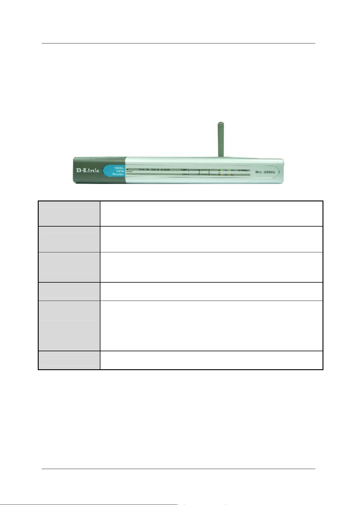
Front Panel Display
Place the Router in a location that permits an easy view of the LED indicators on the front panel.
The LED indicators on the front panel include the Power, Status, ADSL Link/Act, WLAN, LAN (1-4)
Link/Act and PPP/Mail indicators. The ADSL and Ethernet indicators monitor link status and activity
(Link/Act).
Power
Status
ADSL: Link/Act
WLAN
LAN 1 - 4: Link/Act
PPP / MAIL
Steady green light indicates the unit is powered on. When the device is powered
off this remains dark.
Lights steady green during power on self-test (POST). Once the connection
status has been settled, the light will blink green. If the indicator lights steady
green after the POST, the system has failed and the device should be rebooted.
Steady green light indicates a valid ADSL connection. This will light after the
ADSL negotiation process has been settled. A blinking green light indicates
activity on the WAN (ADSL) interface.
Lit green when the wireless connection is established. A blinking green when
sending/receiving data.
Green: The router has a successful 100Mb Ethernet connection. A solid green
light indicates a valid link on startup. These lights blink when there is activity
currently passing through the Ethernet port.
Orange: The router has a successful 10Mb Ethernet connection. A solid green
light indicates a valid link on startup. These lights blink when there is activity
currently passing through the Ethernet port.
Lit steady when there is a PPPoA / PPPoE connection. Lit and flashed
periodically when there is email in the Inbox
4
Page 13
DSL-G804V Wireless ADSL Router User’s Guide
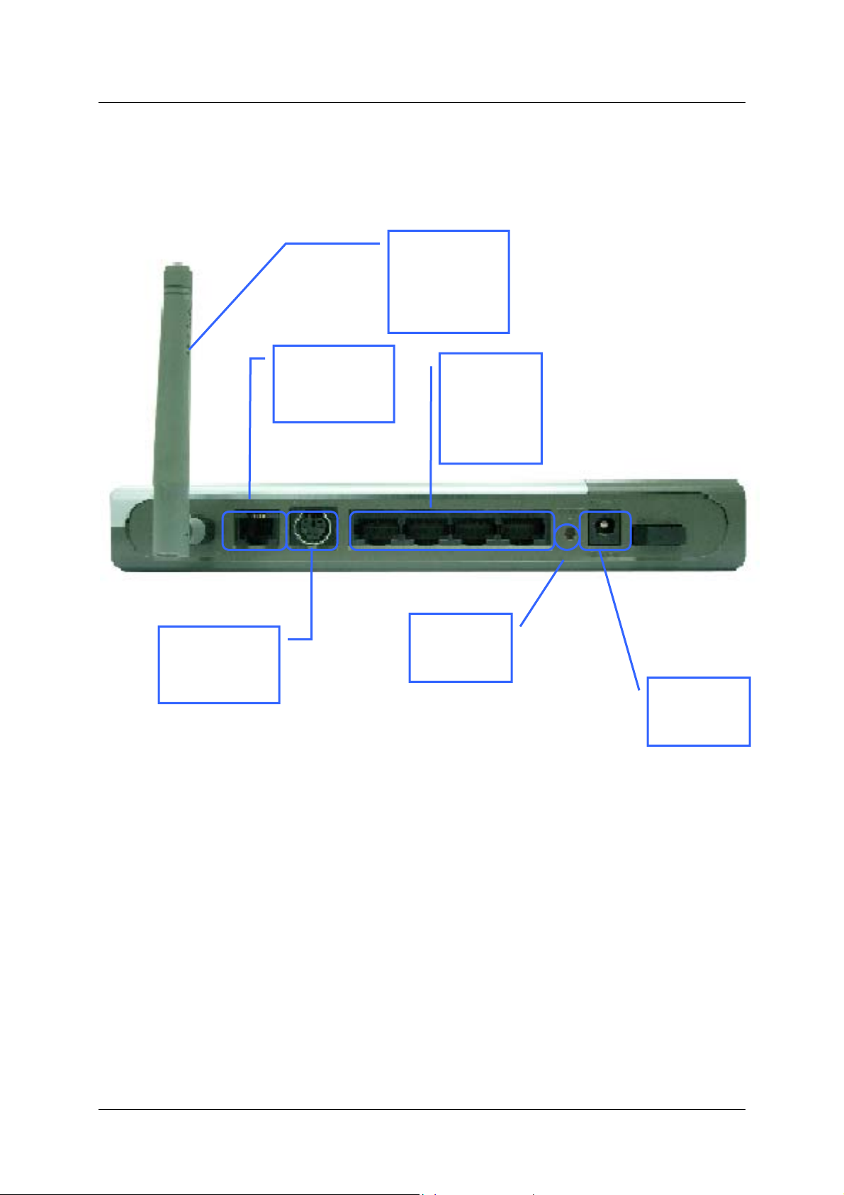
Rear Panel Connections
All cable connections to the Router are made at the rear panel. Connect the power adapter here to power on the
Router. Use the Reset button to restore the settings to the factory default values.
Antenna,
Ensure good
wireless
reception
ADSL port,
connect ADSL
cable here
Console port,
connect
PS2/RS-232
Ethernet
ports,
connect
Ethernet
cable here
Factory
Reset
button
Power cord
connects
here
5
Page 14

DSL-G804V Wireless ADSL Router User’s Guide
2
Hardware Installation
The DSL-G804V maintains five separate interfaces, four Ethernet and one ADSL interface. Place the Router in a
location where it can be safely connected to the various devices as well as to a power source. The Router should
not be located where it will be exposed to moisture or excessive heat. Make sure the cables and power cord are
placed safely out of the way so they do not create a tripping hazard. As with any electrical appliance, observe
common sense safety precautions.
The access point can be placed on a shelf or desktop, ideally you should be able to see the LED indicators on the
front if you need to view them for troubleshooting.
Power on Router
CAUTION: The Router must be used with the power adapter included with the device.
To power on the Router:
1. Insert the DC Power Adapter cord into the power receptacle located on the rear panel of the Router and plug
the adapter into a suitable nearby power source.
2. You should see the Power LED indicator light up and remain lit. The Status LED should light solid green
and begin to blink after a few seconds.
3. If the Ethernet port is connected to a working device, check the Ethernet Link/Act LED indicators to make
sure the connection is valid. The Router will attempt to establish the ADSL connection, if the ADSL line is
connected and the Router is properly configured this should light up after several seconds. If this is the first
time installing the device, some settings may need to be changed before the Router can establish a
connection.
Factory Reset Button
The Router may be reset to the original factory default settings by depressing the reset button for a few seconds
while the device is powered on. Use a ballpoint or paperclip to gently push down the reset button. Remember
that this will wipe out any settings stored in flash memory including user account information and LAN IP
settings. The factory default IP address of the Router is 192.168.1.1 and the subnet mask is 255.255.255.0, the
default management Username is admin and the default Password is admin.
6
Page 15
DSL-G804V Wireless ADSL Router User’s Guide
r
r
Network Connections
Network connections are provid ed through the ADSL por t and the four Ethernet por ts on the back of the Router .
See the Rear Panel diagram above and the illustrations below for examples.
Connect ADSL Line
Use the ADSL cable included with the Router to connect it to a telephone wall socket or receptacle. Plug one end
of the cable into the ADSL port (RJ-11 receptacle) on the rear panel of the Router and insert the other end into
the RJ-11 wall socket. If you are using a low pass filter device, follow the instructions included with the device
or given to you by your service provider. The ADSL connection represents the WAN interface, the connection to
the Internet. It is the physical link to the service provider’s network backbone and ultimately to the Internet.
Connect Router to Ethernet
The Router may be connected to a single computer or Ethernet device through the 10BASE-TX Ethernet port on
the rear panel. Any connection to an Ethernet concentrating device such as a switch or hub must operate at a
speed of 10/100 Mbps only. When connecting the Router to any Ethernet device that is capable of operating at
speeds higher than 10Mbps, be sure that the device has auto-negotiation (NWay) enabled for the connecting port.
Use standard twisted-pair cable with RJ-45 connectors. The RJ-45 port on the Router is a crossed port (MDI-X).
Follow standard Ethernet guidelines when deciding what type of cable to use to make this connection. When
connecting the Router directly to a PC or server use a normal straight-thr ough cable. You should use a crossed
cable when connecting the Router to a normal (MDI-X) port on a switch or hub. Use a normal straight-through
cable when connecting it to an uplink (MDI-II) port on a hub or switch.
The rules governing Ethernet cable lengths apply to the LAN to Router connection. Be sure that the cable
connecting the LAN to the Router does not exceed 100 meters.
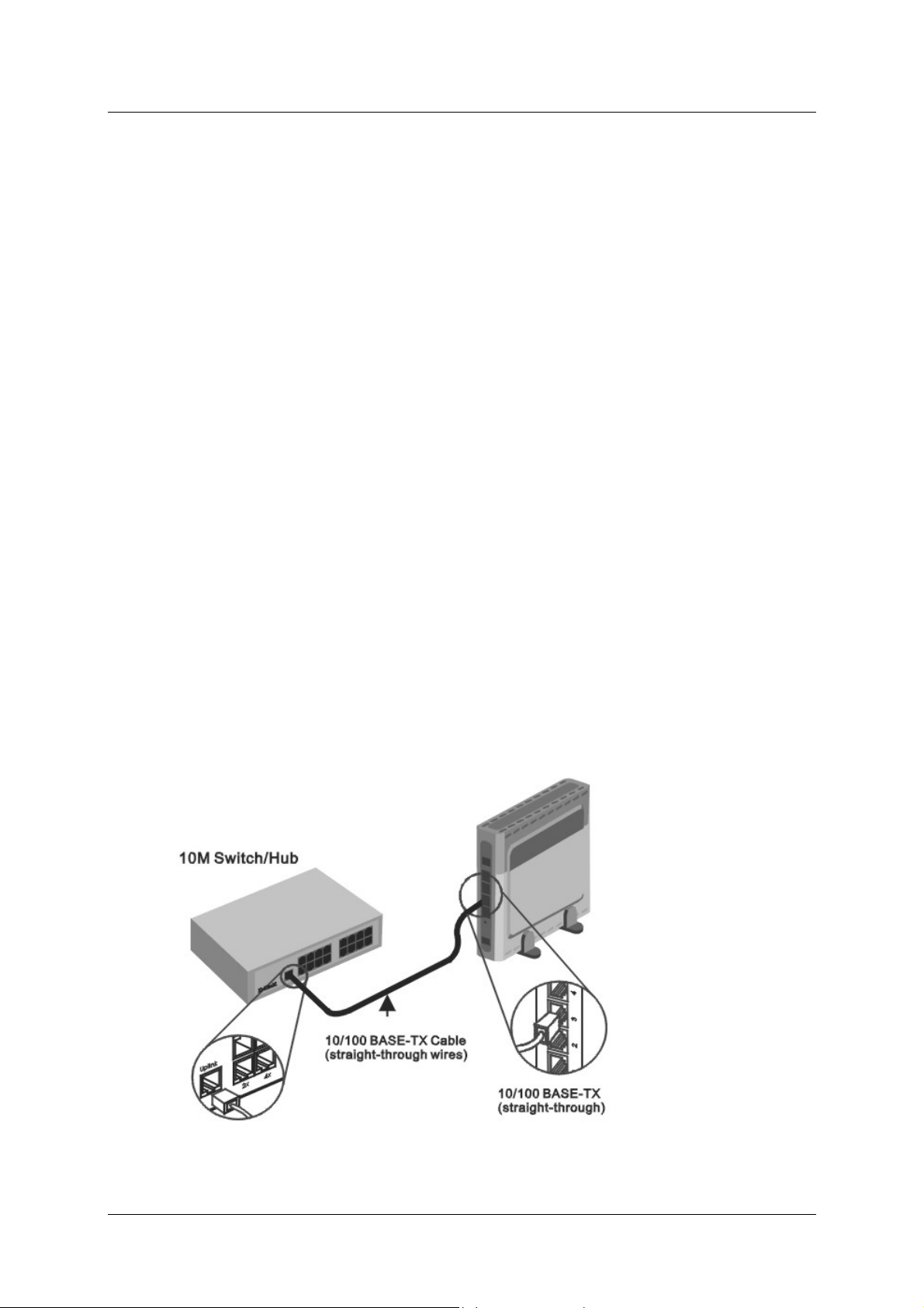
Hub or Switch to Router Connection
Connect the Router to an uplink port (MDI-II) on an Ethernet hub or switch with a straight-through cable as
shown in the diagram below:
If you wish to reserve the
uplink port on the switch o
hub for another device,
connect to any on the othe
MDI-X ports (1x, 2x, etc.)
with a crossed cable.
7
Page 16
DSL-G804V Wireless ADSL Router User’s Guide
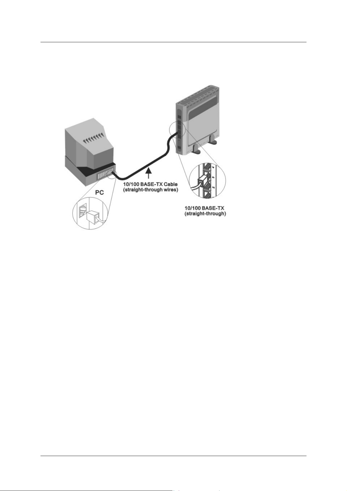
Computer to Router Connection
You can connect the
Router directly to a
10/100BASE-TX
Ethernet adapter card
(NIC) installed on a
PC using the Ethernet
cable provided as
shown in this diagram.
Power On Router
To power on the Router:
1. Insert the DC Power Adapter cord into the power receptacle located on the rear panel of the Router and plug
the adapter into a suitable nearby power source.
2. You should see the Power LED indicator light up and remain lit. The Status LED should light solid green
and begin to blink after a few seconds.
3. If you have the Router connected to your network you can look at the Ethernet Link/Act LED indicators to
make sure they have valid connections. The Router will attempt to establish the ADSL connection, if the
ADSL line is connected and the connection is properly configured this should light up after several seconds.
Factory Reset Button
The Router may be reset to the original factory default settings by depressing the reset button for a few seconds
while the device is powered on. Use a ballpoint or paperclip to push down the reset button. Remember that this
will wipe out any settings stored in flash memory including IP settings. The factory default IP address of the
Router is 192.168.1.1 and the subnet mask is 255.255.255.0.
8
Page 17

DSL-G804V Wireless ADSL Router User’s Guide
3
Basic Router Configuration
The first time you setup the Router it is recommended that you configure the WAN connection using a single
computer making sure that both the computer and the Router are not connected to the LAN. Once the WAN
connection is functioning properly, you may continue to make changes to Router configuration including IP
settings and DHCP setup. This chapter is concerned with using your computer to configur e the WAN co nnection .
The following chapter describes the various menus used to configure and monitor the Router including how to
change IP settings and DHCP server setup.
Wan Configuration Summary
1. Connect to the Router To configure the WAN connection used by the Router it is first necessary to
communicate with the Router through its management interface, which is HTML-based and can be
accessed using a web browser. To access the management software your computer must be able to
“see” the Router. Your computer can see the Router if it is in the same “neighborhood” or subnet as the
Router. This is accomplished by making sure your computer has IP settings that place it in the same
subnet as the Router. The easiest way to make sure your computer has the correct IP settings is to
configure it to use the DHCP server in the Router. The next section describes how to change the IP
configuration for a computer running a Windows operating system to be a DHCP client.
2. Configure the WAN Connection Once your are able to access the configuration software you can
proceed to change the settings required to establish th e ADSL connection and connect to the service
provider’s network. There are different methods used to establish the connection to the service
provider’s network and ultimately to the Internet. You shou ld know what Encapsulation and conn ection
type you are required to use for your ADSL service. It is also possible that you must chang e the PVC
settings used for the ADSL connection. Your service provider should provide all the information you
need to configure the WAN connection.
Configuring IP Settings on Your Computer
In order to configure your system to receive IP settings from the Router it must first have the TCP/IP protocol
installed. If you have an Ethernet port on your computer, it probably already has TCP/IP protocol installed. If
you are using Windows XP the TCP/IP is enabled by default for standard installations. Below is an illustrated
example of how to configure a Windows XP system to automatically obtain IP settings from the Router.
Following this example is a step-by-step description of the procedures used on the other Windows operating
systems to first check if the TCP/IP protocol has been installed; if it is not, instructions are provided for
installing it. Once the protocol has been installed you can configure the system to receive IP settings from the
Router.
For computers running non-Windows operating systems, follow the instructions for your OS that configure the
system to receive an IP address from the Router, that is, configure the system to be a DHCP client.
If you are using this Router to provide Internet access for more than one computer, you
Note
can use these instructions later to change the IP settings for the other computers.
However, you cannot use the same IP address since every computer must have its own
IP address that is unique on the local network.
9
Page 18
DSL-G804V Wireless ADSL Router User’s Guide
Configure Windows XP for DHCP
Use the following steps to configure a computer running Windows XP to be a DHCP client.
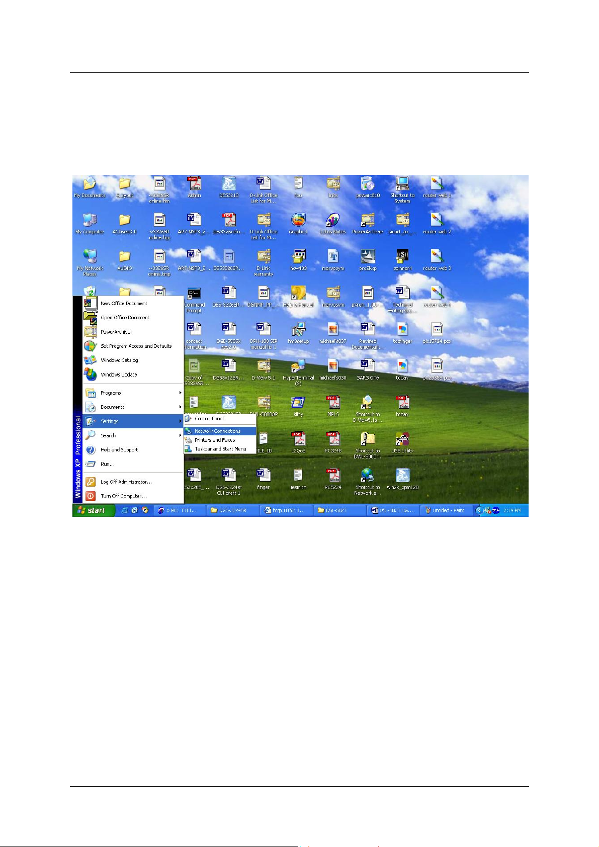
1. From the Start menu on your desktop, go to Settings, then click on Network Connections.
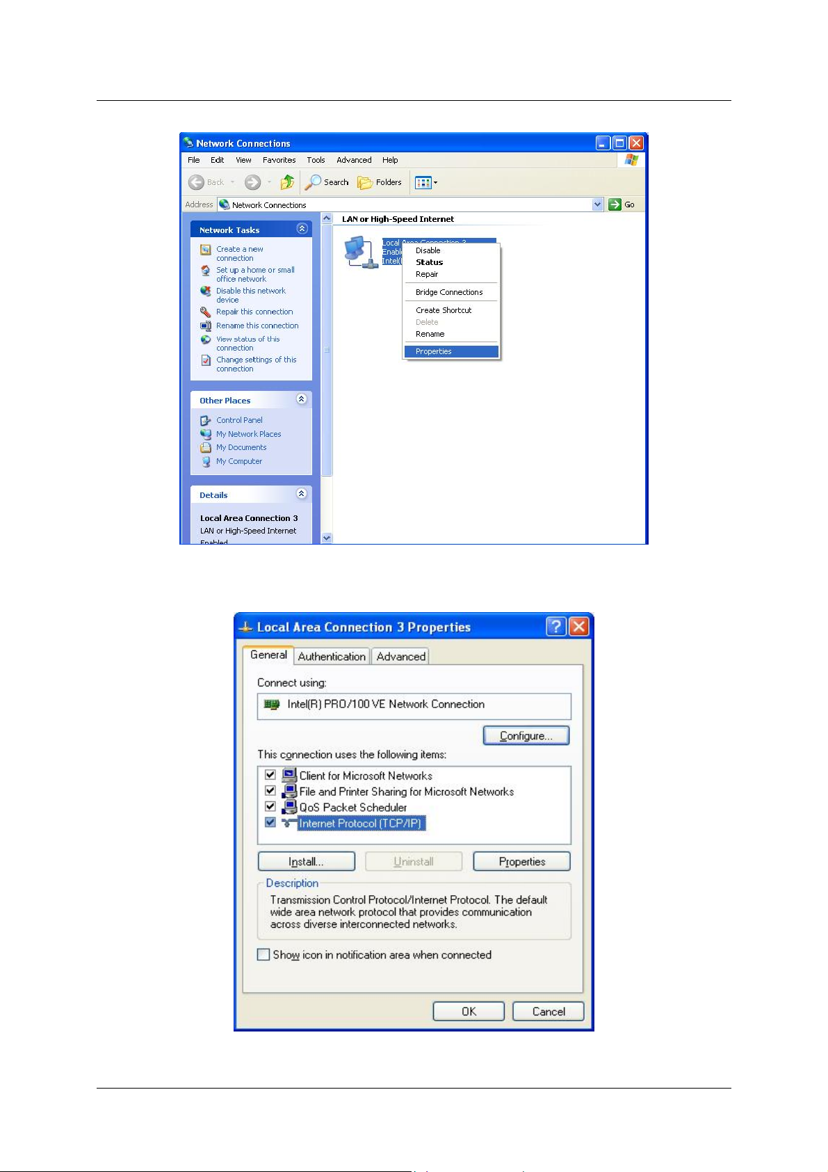
2. In the Network Connections window, right-click on LAN (Local Area Connection), then click
Properties.
10
Page 19
DSL-G804V Wireless ADSL Router User’s Guide
3. In the General tab of the Local Area Connection Properties menu, highlight Internet Protocol
(TCP/IP) under “This connection uses the following items:” by clicking on it once. Click on the
Properties button.
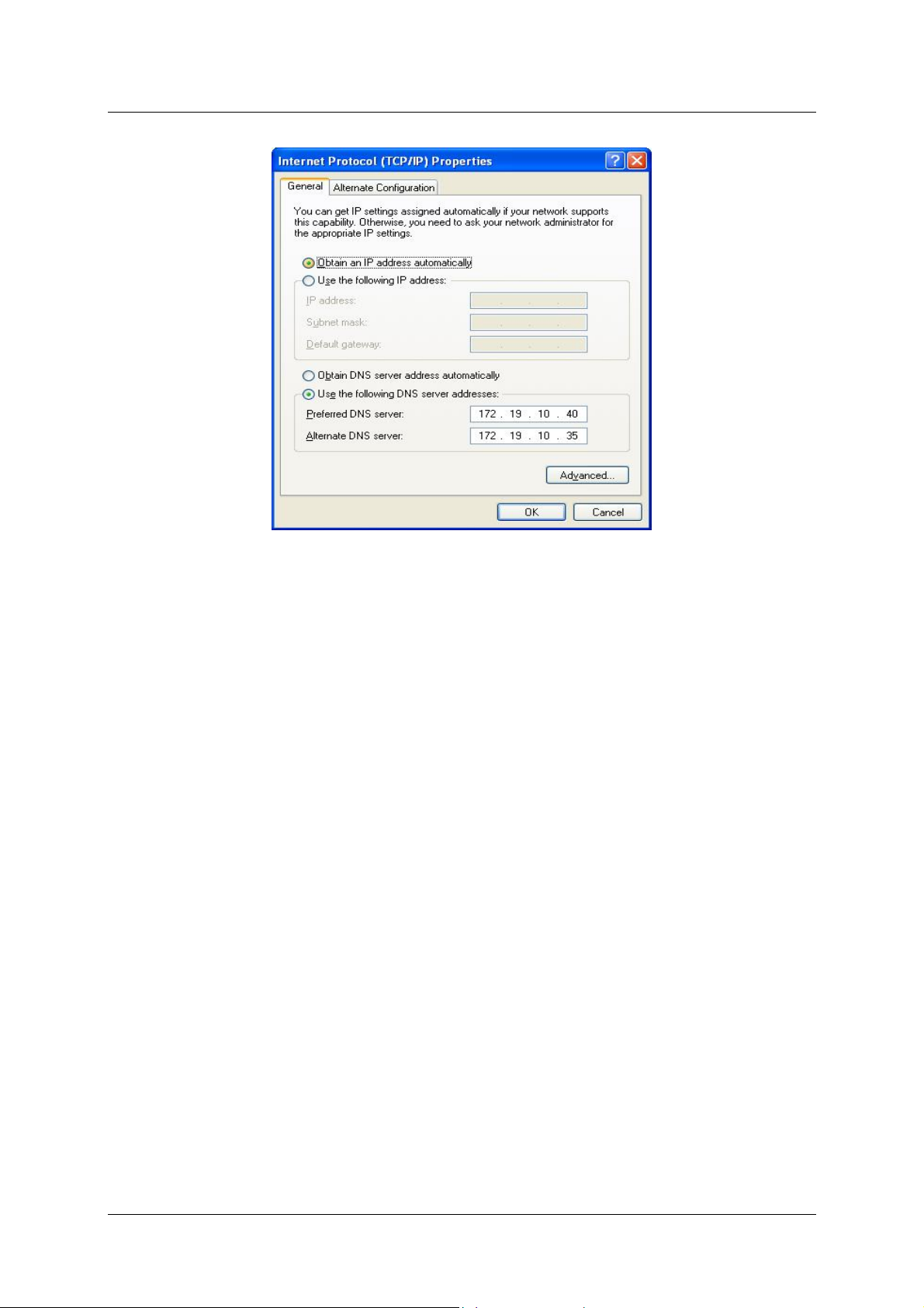
4. Select “Obtain an IP address automatically” by clicking once in the circle. Click the OK button.
11
Page 20
DSL-G804V Wireless ADSL Router User’s Guide
Your computer is now ready to use the Router’s DHCP server.
Windows 2000
First, check for the IP protocol and, if necessary, install it:
1. In the Windows task bar, click the Start button, point to Settings, and then click Control Panel.
2. Double-click the Network and Dial-up Connections icon.
3. In the Network and Dial-up Connections window, right-click the Local Area Connection icon, and
then select Properties.
4. The Local Area Connection Properties dialog box displays with a list of currently installed network
components. If the list includes Internet Protocol (TCP/IP), then the protocol has already been enabled,
skip ahead to Configure Windows 2000 for DHCP.
5. If Internet Protocol (TCP/IP) does not display as an installed component, click Install.
6. In the Select Network Component Type dialog box, select Protocol, and then click Add.
7. Select Internet Protocol (TCP/IP) in the Network Protocols list, and then click OK.
8. You may be prompted to install files from your Windows 2000 installation CD or other media. Follow
the instructions to install the files.
9. If prompted, click OK to restart your computer with the new settings.
Configure Windows 2000 for DHCP
1. In the Control Panel, double-click the Network and Dial-up Connections icon.
2. In Network and Dial-up Connections window, right-click the Local Area Connection icon, and then
select Properties.
3. In the Local Area Connection Properties dialog box, select Internet Protocol (TCP/IP), and then
click Properties.
4. In the Internet Protocol (TCP/IP) Properties dialog box, click the button labeled Obtain an IP
address automatically.
5. Double-click OK to confirm and save your changes, and then close the Control Panel.
Your computer is now ready to use the Router’s DHCP server.
12
Page 21

DSL-G804V Wireless ADSL Router User’s Guide
Windows ME
First, check for the IP protocol and, if necessary, install it:
1. In the Windows task bar, click the Start button, point to Settings, and then click Control Panel.
2. Double-click the Network and Dial-up Connections icon.
3. In the Network and Dial-up Connections window, right-click the Network icon, and then select
Properties.
4. The Network Properties dialog box displays with a list of currently installed network components. If
the list includes Internet Protocol (TCP/IP), then the protocol has already been enabled. Skip ahead to
Configure Windows ME for DHCP.
5. If Internet Protocol (TCP/IP) does not display as an installed component, click Add.
6. In the Select Network Component Type dialog box, select Protocol, and then click Add.
7. Select Microsoft in the Manufacturers box.
8. Select Internet Protocol (TCP/IP) in the Network Protocols list, and then click OK.
9. You may be prompted to install files from your Windows Me installation CD or other media. Follow
the instructions to install the files.
10. If prompted, click OK to restart your computer with the new settings.
Configure Windows ME for DHCP
1. In the Control Panel, double-click the Network and Dial-up Connections icon.
2. In the Network and Dial-up Connections window, right-click the Network icon, and then select
Properties.
3. In the Network Properties dialog box, select TCP/IP, and then click Properties.
4. In the TCP/IP Settings dialog box, click the Obtain and IP address automatically option.
5. Double-click OK twice to confirm and save your changes, and then close the Control Panel.
Your computer is now ready to use the Router’s DHCP server.
Windows 95 and Windows 98
First, check for the IP protocol and, if necessary, install it:
1. In the Windows task bar, click the Start button, point to Settings, and then click Control Panel.
Double-click the Network icon.
2. The Network dialog box displays with a list of currently installed network components. If the list
includes TCP/IP, and then the protocol has already been enabled, skip to Configure IP Information
Windows 95, 98.
3. If TCP/IP does not display as an installed component, click Add. The Select Network Component
Type dialog box displays.
4. Select Protocol, and then click Add. The Select Network Protocol dialog box displays.
5. Click on Microsoft in the Manufacturers list box, and then click TCP/IP in the Network Protocols list
box.
6. Click OK to return to the Network dialog box, and then click OK again. You may be prompted to
install files from your Windows 95/98 installation CD. Follow the instructions to install the files.
7. Click OK to restart the PC and complete the TCP/IP installation.
13
Page 22

DSL-G804V Wireless ADSL Router User’s Guide
Configure Windows 95 and Windows 98 for DHCP
1. Open the Control Panel window, and then click the Network icon.
2. Select the network component labeled TCP/IP, and then click Properties.
3. If you have multiple TCP/IP listings, select the listing associated with your network card or adapter.
4. In the TCP/IP Properties dialog box, click the IP Address tab.
5. Click the Obtain an IP address automatically option.
6. Double-click OK to confirm and save your changes. You will be prompted to restart Windows.
7. Click Yes.
When it has restarted your computer is ready to use the Router’s DHCP server.
Windows NT 4.0 Workstations
First, check for the IP protocol and, if necessary, install it:
1. In the Windows NT task bar, click the Start button, point to Settings, and then click Control Panel.
2. In the Control Panel window, double-click the Network icon.
3. In the Network dialog box, click the Protocols tab.
4. The Protocols tab displays a list of currently installed network protocols. If the list includes TCP/IP,
then the protocol has already been enabled. Skip to “Configure IP Information”
5. If TCP/IP does not display as an installed component, click Add.
6. In the Select Network Protocol dialog box, select TCP/IP, and then click OK. You may be prompted
to install files from your Windows NT installation CD or other media. Follow the instructions to install
the files.
7. After all files are installed, a window displays to inform you that a TCP/IP service called DHCP can be
set up to dynamically assign IP information.
8. Click Yes to continue, and then click OK if prompted to restart your computer.
Configure Windows NT 4.0 for DHCP
1. Open the Control Panel window, and then double-click the Network icon.
2. In the Network dialog box, click the Protocols tab.
3. In the Protocols tab, select TCP/IP, and then click Properties.
4. In the Microsoft TCP/IP Properties dialog box, click the Obtain an IP address automatically option.
5. Click OK twice to confirm and save your changes, and then close the Control Panel.
14
Page 23
DSL-G804V Wireless ADSL Router User’s Guide
Access the Configuration Manager
Now that your computer’s IP settings allow it to communicate with the Router, you can access the configuration
software.
Be sure that the web browser on your computer is not configured to use a proxy server
in the Internet settings. In Windows Internet Explorer, you can check if a proxy server is
enabled using the following procedure:
1. In Windows, click on the Start button, go to Settings and choose Control Panel.
2. In the Control Panel window, double-click on the Internet Options icon.
Note
To use the web-based management software, launch a suitable web browser and direct it to the IP address of the
Router. Type in http:// followed by the default IP address, 192.168.1.1 in the address bar of the browser. The
URL in the address bar should read: http://192.168.1.1.
3. Click the Connections tab and click on the LAN Settings button.
4. Verify that the “Use proxy server” option is NOT checked. If it is checked, click in the
checked box to deselect the option and click OK.
Alternatively, you can access this Internet Options menu using the Tools pull-down
menu in Internet Explorer.
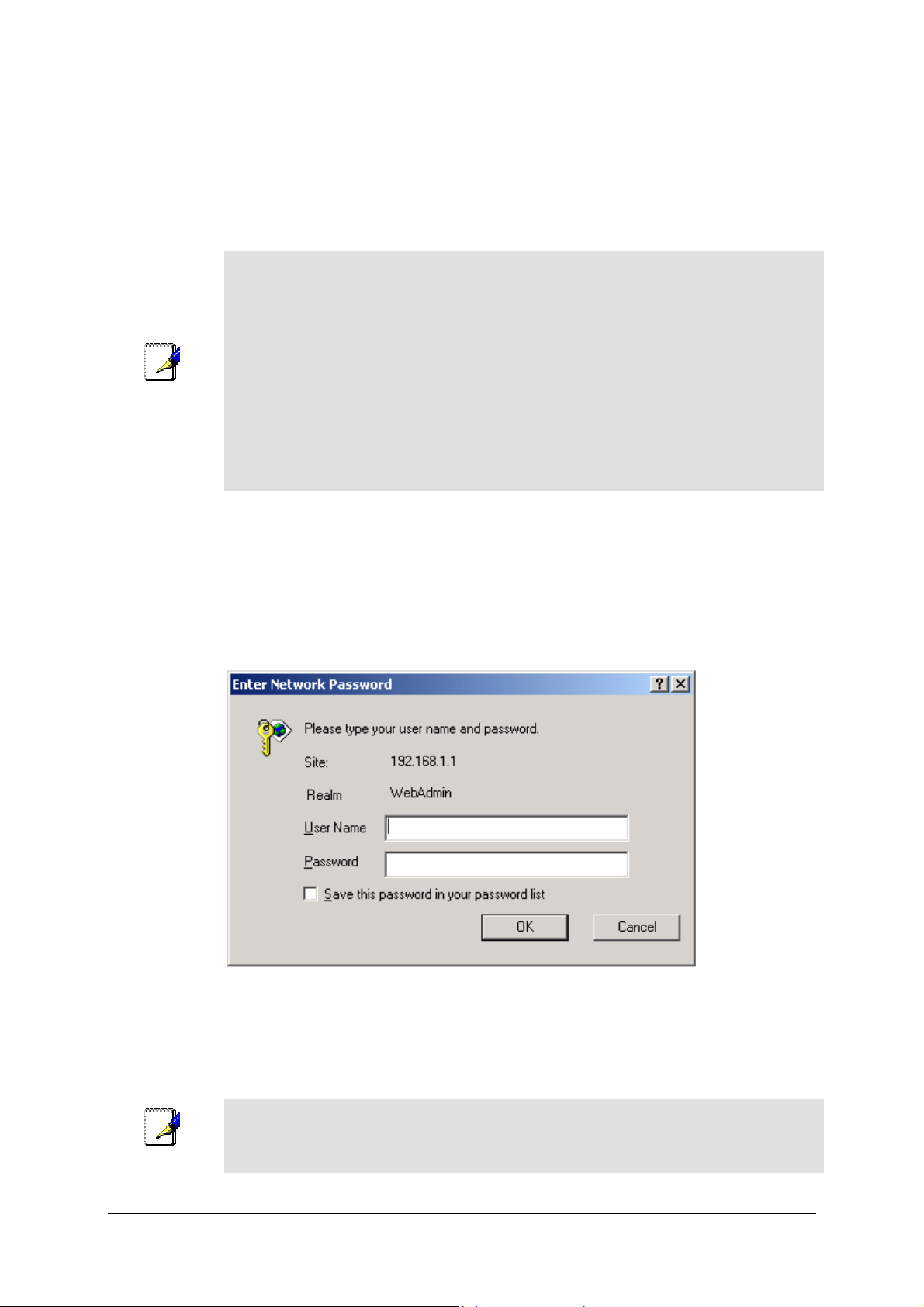
Login to Home Page
A new window will appear and you will be prompted for a user name and password to access the web-based
manager.
Figure 3-1. Home - Login window
Use the default user name admin and password admin for first time setup. You should change the web-based
manager access user name and password once you have verified that a connection can be established. The user
name and password allows any PC within the same subnet as the Modem to access the web-based manger.
Do not confuse the user name and password used to access the web-based manager
Note
with the ADSL account user name and password needed for PPP connections to
access the service provider’s network.
15
Page 24
DSL-G804V Wireless ADSL Router User’s Guide
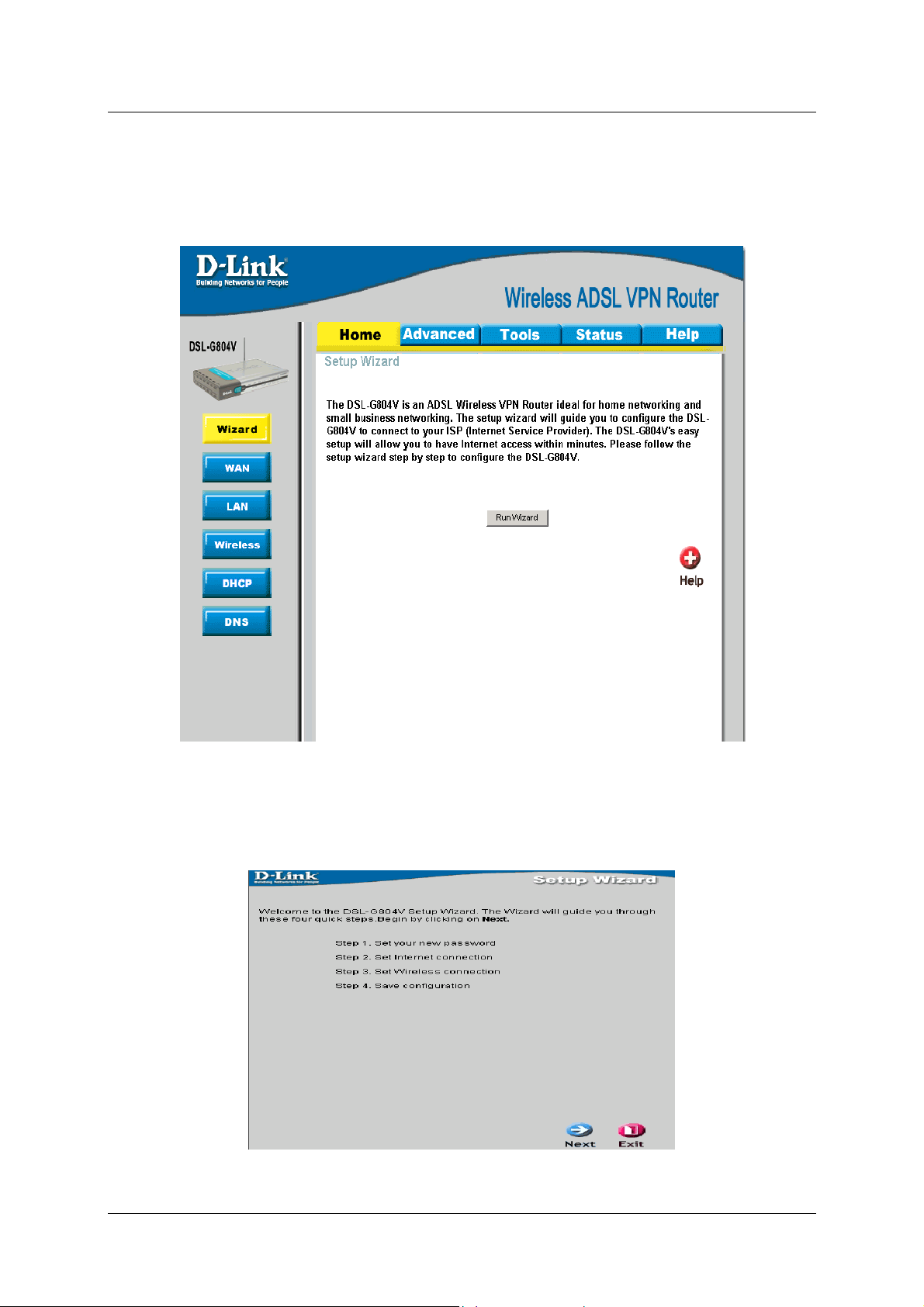
Configure the Router
The first page that appears after you successfully login di splays information about the Ro uter and its connection
status. Tabs across the top of the screen show other available menus: Setup, Advanced, Tools, Status, and Help.
Figure 3-2. Home – Status Information window
When the Router is used to provide Internet access it actually must first access your service provider’s network,
that is, it must communicate with computers and other routers owned by your service provider. These computers
and routers then provide access to the Internet. The Router must be configured to communicate with the systems
that give it access to the larger network. Click the Run Wizard tab; the Setup Wizard window will appear.
Figure 3-3. Home – Setup Wizard window
16
Page 25
DSL-G804V Wireless ADSL Router User’s Guide
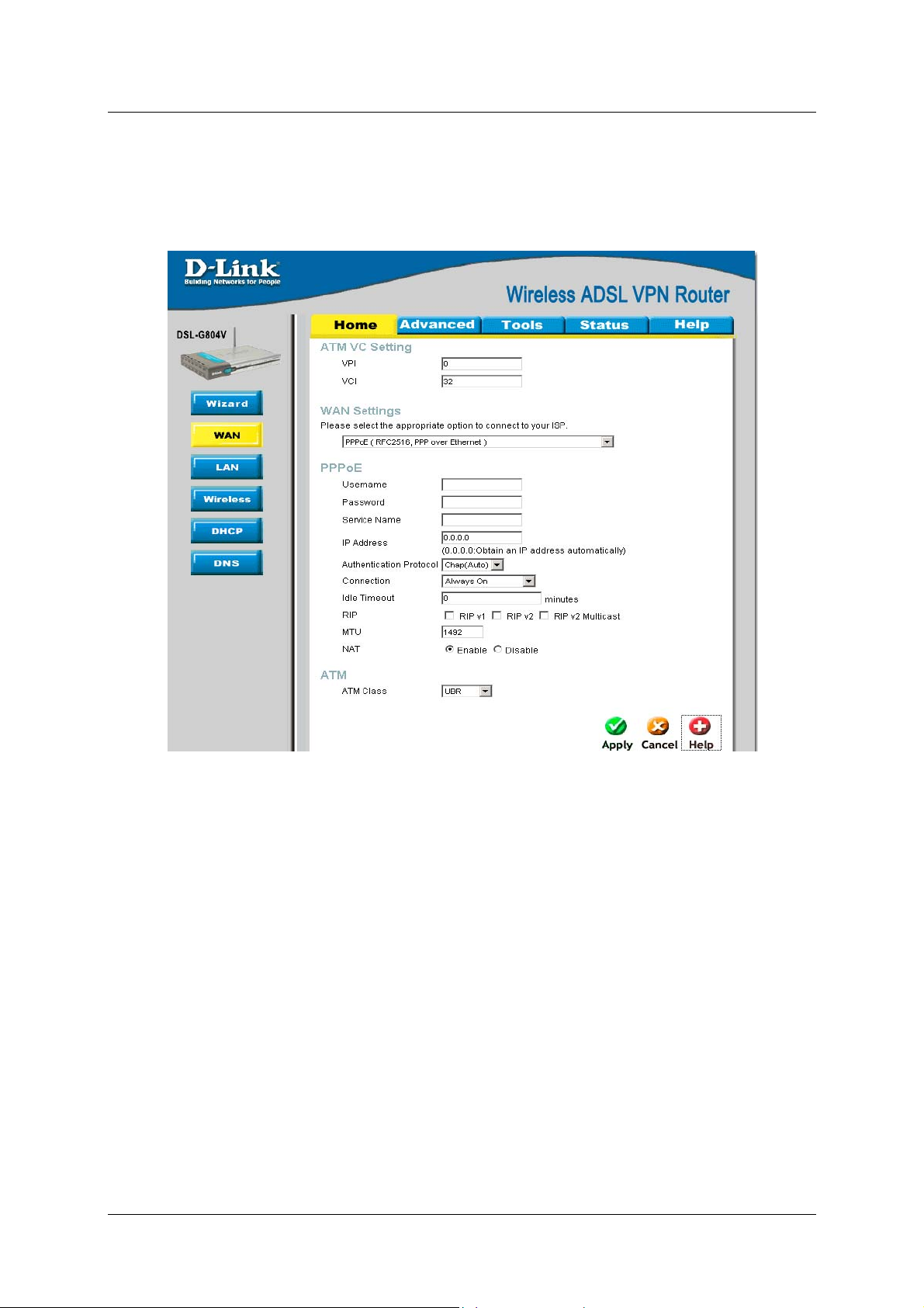
WAN
The WAN windows provide needed information to the WAN (Wide Area Network) Settings in order to get
connected to your ISP (Internet Service Provider). The WAN settings are giv en by your ISP; please con tact your
ISP for more information if needed.
Figure 3-4. WAN Setup window - PPPoE
ATM VC Setting
VC, known as Virtual Circuit or Virtual Channel, is a virtual path in which a communication session is
established. Check with your ISP for information.
WAN Setting – Please select the appropriate option to connect to your ISP. There are five options: PPPoA (RFC
2864, PPP over AAL5), PPPoE (RFC2516, PPP over Ethernet), MPoA (RFC 1483/RFC 2684, Multiprotocol
Encapsulation over AAL5), IPoA (RFC 1577, Classic IP and ARP over ATM) and Pure Bridge.
17
Page 26

DSL-G804V Wireless ADSL Router User’s Guide
PPPoE (RFC2516, PPP over Ethernet)
Select this option if your ISP requires you to use the PPPoE (Point-to-Point Protocol over Ethernet) connection.
Parameter Description
Username
Password
Service Name
IP Address
Authentication
Protocol
Connection
Idle Timeout
RIP (Routing
Information
Protocol)
Enter your username given by your ISP. This is case sensitive and uses the
format of "username" instead of
username@ispname.
Enter your password given by your ISP. This is case sensitive.
(optional) This is for identification purpose. If this is requested, you will get
informed by your ISP. Maximum input is 20 alphanumeric characters.
(optional) This option is only available if you have given a fixed IP address
from your ISP. Enter 0.0.0.0 to get a random assigned IP from your ISP;
Username and Password must be entered.
Default is Chap(Auto). Your ISP will advise you whether to use Chap or Pap.
How you like establish your PPPoE connection, Always on or Connect on
Demand.
Always on: If you want the router to establish a PPPoE session when starting
up and to automatically re-establish the PPPoE session when disconnected by
the ISP.
Connect to Demand: If you want to establish a PPPoE session only when
there is a packet requesting access to the Internet (i.e. when a program on
your computer attempts to access the Internet).
Auto-disconnect the PPPoE connection when there is no activity on the line for
a predetermined period of time.
It is an interior routing protocol for router to exchange routing information.
MTU (Maximum Transmission Unit): This is the size of largest datagram
(excluding media-specific headers) that IP will attempt to send through the
interface. The default setting is 1492.
NAT (Network
Address
Translation)
ATM Class
This allows multiple users to access the Internet through a single ISP account,
sharing a single IP address. If users on your LAN have public IP addresses
and can access the Internet directly, the NAT function can be disabled.
The Quality of Service for ATM layer.
18
Page 27

DSL-G804V Wireless ADSL Router User’s Guide
PPPoE - Advanced Options:
Parameter Description
LLC Header
Create Route
Specific Route
Subnet Mask
Route Mask
MRU
Discover Primary /
Secondary DNS
Give DNS to Relay
Selects encapsulation mode, true for using LLC or false for using VC-Mux.
This setting specifies whether a route is added to the system after IPCP
(Internet Protocol Control Protocol) negotiation is completed. If set to enabled,
a route will be created which directs packets to the remote end of the PPP link.
Specifies whether the route created when a PPP link comes up is a specific or
default route. If set to enabled, the route created will only apply to packets for
the subnet at the remote end of the PPP link. The address of this subnet is
obtained during IPCP negotiation.
Sets the subnet mask used for the local IP interface connected to the PPP
transport. If the value 0.0.0.0 is supplied, the netmask will be calculated from
the class of the IP address obtained during IPCP negotiation.
Sets the subnet mask used by the route that is created when a PPP link
comes up. If it is set to 0.0.0.0, the subnet mask is determined by the IP
address of the remote end of the link. The class of the IP address is obtained
during IPCP (Internet Protocol Control Protocol) negotiation.
Maximum Receive Unit. This is negotiated during the LCP protocol stage.
This setting enables/disables whether the primary/secondary DNS server
address is requested from a remote PPP peer using IPCP. The default setting
for this command is enabled.
Controls whether the PPP Internet Protocol Control Protocol (IPCP) can
request the DNS server IP address for a remote PPP peer. Once IPCP has
discovered the DNS server IP address, it automatically gives the address to
the local DNS relay so that a connection can be established.
Give DNS to Client
Give DNS to DHCP
Server
Discover Primary
NBNS / Discover
Secondary NBNS
Discover Subnet
Mask
Give Subnet Mask
To DHCP Server
Controls whether the PPP Internet Protocol Control Protocol (IPCP) can
request a DNS server IP address for a remote PPP peer. Once IPCP has
discovered the DNS server IP address, it automatically gives the address to
the local DNS client so that a connection can be established.
Similar to the above, but gives the DNS server address to the DHCP server.
This setting enables/disables whether the primary/secondary NBNS server
address is requested from a remote PPP peer using IPCP. The default setting
for this command is disabled.
Specifies if the subnet mask given by IPCP negotiation process is to be used
Enable to change your DHCP Server settings by using the given information in
IPCP negotiation process.
19
Page 28
DSL-G804V Wireless ADSL Router User’s Guide
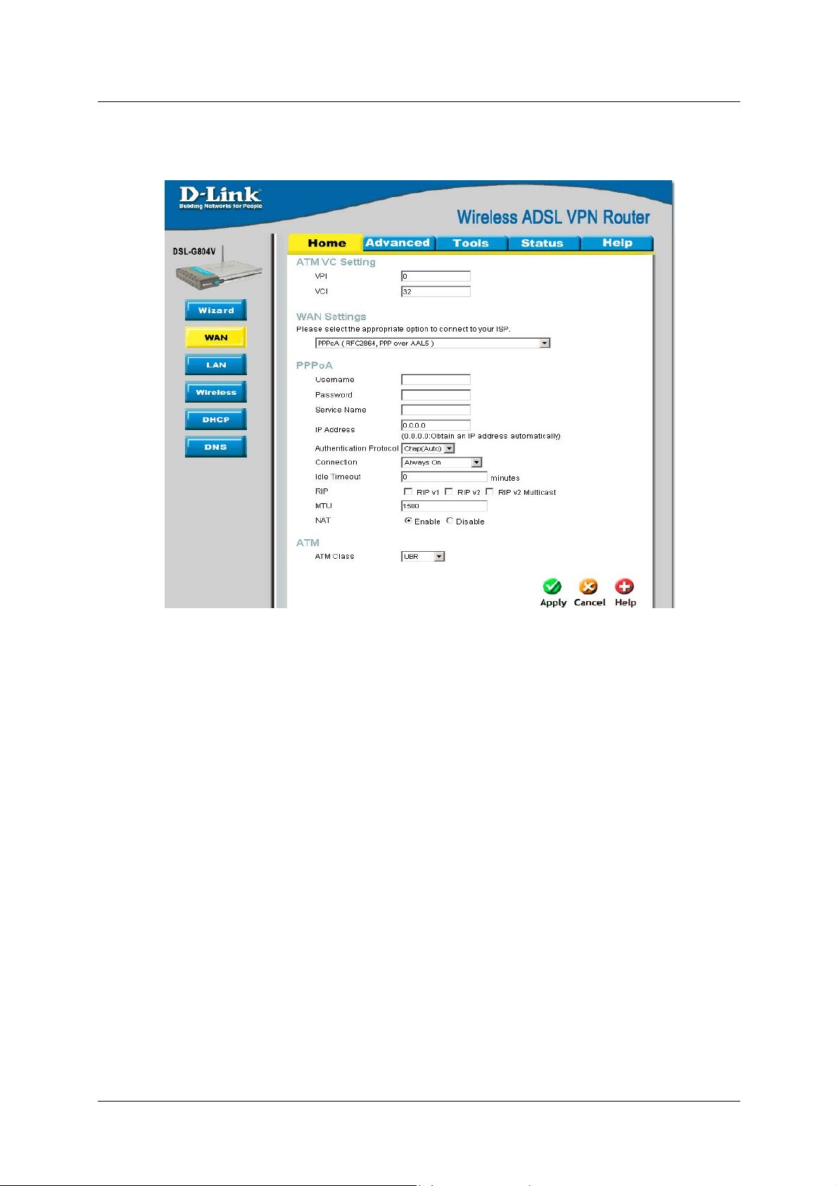
PPPoA (RFC2864, PPP over AAL5)
Select this option if your ISP requires you to use the PPPoA (Point-to-Point Protocol over ATM) connection.
Figure 3-5. WAN Setup window - PPPoA
20
Page 29

DSL-G804V Wireless ADSL Router User’s Guide
Parameter Description
Username
Password
Service Name
IP Address
Authentication
Protocol
Connection
Idle Timeout
RIP (Routing
Information
Protocol)
Enter your username given by your ISP. This is case sensitive and uses the
format of "username" instead of
username@ispname.
Enter your password given by your ISP. This is case sensitive.
(optional) This is for identification purpose. If this is requested, you will get
informed by your ISP. Maximum input is 20 alphanumeric characters.
(optional) This option is only available if you have given a fixed IP address
from your ISP. Enter 0.0.0.0 to get a random assigned IP from your ISP;
Username and Password must be entered.
Default is Chap(Auto). Your ISP will advise you whether to use Chap or Pap.
How you like establish your PPPoA connection, Always on or Connect on
Demand.
Always on: If you want the router to establish a PPPoA session when starting
up and to automatically re-establish the PPPoE session when disconnected by
the ISP.
Connect to Demand: If you want to establish a PPPoA session only when
there is a packet requesting access to the Internet (i.e. when a program on
your computer attempts to access the Internet).
Auto-disconnect the PPPoA connection when there is no activity on the line for
a predetermined period of time.
It is an interior routing protocol for router to exchange routing information.
MTU (Maximum
Transmission Unit)
NAT (Network
Address
Translation)
ATM Class
This is the size of largest datagram (excluding media-specific headers) that IP
will attempt to send through the interface. The default setting is 1500.
This allows multiple users to access the Internet through a single ISP account,
sharing a single IP address. If users on your LAN have public IP addresses
and can access the Internet directly, the NAT function can be disabled.
The Quality of Service for ATM layer.
21
Page 30

DSL-G804V Wireless ADSL Router User’s Guide
PPPoA - Advanced Options:
Parameter Description
LLC Header
Create Route
Specific Route
Subnet Mask
Route Mask
MRU
Discover Primary /
Secondary DNS
Give DNS to Relay
Selects encapsulation mode, true for using LLC or false for using VC-Mux.
This setting specifies whether a route is added to the system after IPCP
(Internet Protocol Control Protocol) negotiation is completed. If set to enabled,
a route will be created which directs packets to the remote end of the PPP link.
Specifies whether the route created when a PPP link comes up is a specific or
default route. If set to enabled, the route created will only apply to packets for
the subnet at the remote end of the PPP link. The address of this subnet is
obtained during IPCP negotiation.
Sets the subnet mask used for the local IP interface connected to the PPP
transport. If the value 0.0.0.0 is supplied, the netmask will be calculated from
the class of the IP address obtained during IPCP negotiation.
Sets the subnet mask used by the route that is created when a PPP link
comes up. If it is set to 0.0.0.0, the subnet mask is determined by the IP
address of the remote end of the link. The class of the IP address is obtained
during IPCP (Internet Protocol Control Protocol) negotiation.
Maximum Receive Unit. This is negotiated during the LCP protocol stage.
This setting enables/disables whether the primary/secondary DNS server
address is requested from a remote PPP peer using IPCP. The default setting
for this command is enabled.
Controls whether the PPP Internet Protocol Control Protocol (IPCP) can
request the DNS server IP address for a remote PPP peer. Once IPCP has
discovered the DNS server IP address, it automatically gives the address to
the local DNS relay so that a connection can be established.
Give DNS to Client
Give DNS to DHCP
Server
Discover Primary
NBNS / Discover
Secondary NBNS
Discover Subnet
Mask
Give Subnet Mask
To DHCP Server
Controls whether the PPP Internet Protocol Control Protocol (IPCP) can
request a DNS server IP address for a remote PPP peer. Once IPCP has
discovered the DNS server IP address, it automatically gives the address to
the local DNS client so that a connection can be established.
Similar to the above, but gives the DNS server address to the DHCP server.
This setting enables/disables whether the primary/secondary NBNS server
address is requested from a remote PPP peer using IPCP. The default setting
for this command is disabled.
Specifies if the subnet mask given by IPCP negotiation process is to be used.
Enable to change your DHCP Server settings by using the given information in
IPCP negotiation process.
22
Page 31

DSL-G804V Wireless ADSL Router User’s Guide
MPoA (RFC1483/RFC2684, Multi protocol Encapsulation over AAL5)
Figure 3-6. WAN Setup window - MPoA
Parameter Description
Encapsulation
Select the encapsulation format, this is provided by your ISP.
Method
IP Assignment
Please click Obtain an IP address automatically via DHCP client to enable
the DHCP client function or click Specify an IP address to disable the DHCP
client function, and specify the IP address, Netmask and Gateway manually.
The setting of this item is specified by your ISP.
RIP (Routing
It is an interior routing protocol for router to exchange routing information.
Information
Protocol)
MTU (Maximum
Transmission Unit)
NAT (Network
Address
Translation)
ATM Class
This is the size of largest datagram (excluding media-specific headers) that IP
will attempt to send through the interface. The default setting is 1500.
This allows multiple users to access the Internet through a single ISP account,
sharing a single IP address. If users on your LAN have public IP addresses
and can access the Internet directly, the NAT function can be disabled.
The Quality of Service for ATM layer.
23
Page 32

DSL-G804V Wireless ADSL Router User’s Guide
IPoA (RFC1577, Classic IP and ARP over ATM)
Figure 3-7. WAN Setup window - IPoA
Parameter Description
IP Assignment
Please click Obtain an IP address automatically via DHCP client to enable
the DHCP client function or click Specify an IP address to disable the DHCP
client function, and specify the IP address, Netmask and Gateway manually.
The setting of this item is specified by your ISP.
RIP (Routing
It is an interior routing protocol for router to exchange routing information.
Information
Protocol)
MTU (Maximum
Transmission Unit)
NAT (Network
Address
Translation)
ATM Class
This is the size of largest datagram (excluding media-specific headers) that IP
will attempt to send through the interface. The default setting is 1500.
This allows multiple users to access the Internet through a single ISP account,
sharing a single IP address. If users on your LAN have public IP addresses
and can access the Internet directly, the NAT function can be disabled.
The Quality of Service for ATM layer.
24
Page 33

Pure Bridge
DSL-G804V Wireless ADSL Router User’s Guide
Figure 3-8. WAN Setup window – Pure Bridge
Parameter Description
Encapsulation
Select the encapsulation format, this is provided by your ISP.
Method
Ether Filter Type
Spanning Bridge
Interface
ATM Class
Specify the type of Ethernet filtering performed by the named bridge interface.
Select Enable/Disable radio button to choose spanning tree function of
modem.
The Quality of Service for ATM layer.
25
Page 34

DSL-G804V Wireless ADSL Router User’s Guide
LAN Settings
LAN (Local Area Network) setting is private to your internal network and cannot be seen from outside world,
Internet. You may configure your LAN by given a LAN IP address to your network.
LAN Settings – LAN IP Configuration
Figure 3-9. Home – LAN Settings (LAN IP Configuration)
Parameter Description
IP Address
Subnet Mask
RIP (Routing
Information
Protocol)
Default setting is 192.168.1.1.
Default setting is 255.255.255.0.
It is an interior routing protocol for router to exchange routing information.
26
Page 35

DSL-G804V Wireless ADSL Router User’s Guide
LAN Settings – Ethernet Client Filter
LAN (Local Area Network) setting is private to your internal network and cannot be seen from outside world,
Internet. You may configure your LAN by given a LAN IP address to your network.
Figure 3-10. Home – LAN Settings (Ethernet Client Filter)
Parameter Description
Filter Action
Select an appreciated filter action, Disable, Allowed (White list), and Blocked
(Blacklist)
Disabled
Allowed (White list)
This inactivates the Ethernet Client Filter function.
This authorizes specific device accessing your LAN by insert the MAC
Address in the space provided. Make sure you PC's MAC is listed.
Blocked (Blacklist)
Check to prevent unwanted device accessing your LAN by insert the MAC
Address in the space provided. Make sure your PC's MAC is NOT listed.
Candidates
Active PC in LAN displays a list of individual Ethernet device’s IP Address &
MAC Address which connecting to the router. You can easily by checking the
box next to the IP address to be blocked or allowed. Then Add to insert to the
Ethernet Client Filter table. The maximum Ethernet client is 16.
27
Page 36
DSL-G804V Wireless ADSL Router User’s Guide
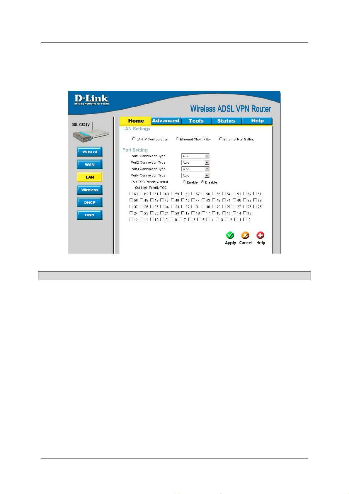
LAN Setting – Ethernet Port Setting
This allows you to configure the settings for the router’s Ethernet ports to solve some of the compatibility
problems that may be encountered while connecting to the Internet, as well allowing users to tweak the
performance of their network.
Figure 3-11. Home – LAN Settings (Ethernet Port Setting)
Parameter Description
Port # Connection
Type
Five options to choose from: Auto, 10M half-duplex, 10M full-duplex, 100M
half-duplex or 100M full-duplex. Sometimes, there are Ethernet compatibility
problems with legacy Ethernet devices, and you can configure different types
to solve compatibility issues. The default is Auto, which users should keep
unless there are specific problems with PCs not being able to access your
LAN.
IPv4 TOS priority
Control (Advanced
users)
Set High Priority
TOS
TOS, Type of Services, is the 2
are reserved and bit 0-2 are used to specify the priority (precedence) of the
packet, and bits 3-5 are specified the delay, throughput and reliability.
This feature uses bits 0-2 to classify the packet’s priority. If the packet is high
priority, it will flow first. Therefore, when this feature is enabled, the router’s
Ethernet switch will check the 2
Precedence of TOS field matches the checked values in the table (0 to 7), this
packet will be treated as high priority.
nd
octet of an IP packet. Bits 6-7 of this octet
nd
octet of each IP packet. If the value in the
28
Page 37

DSL-G804V Wireless ADSL Router User’s Guide
Wireless Settings
Figure 3-12. Home – Wireless Settings
Parameter Description
WLAN Radio
Mode
ESSID
ESSID Broadcast
Regulation Domain
Channel ID
Default setting is set to On. If you do not have any wireless, both 802.11g and
802.11b, device in your network, select Off.
The default setting is 802.11b+g (Mixed mode). If you do not know or have
both 11g and 11b devices in your network, then keep the default in mixed
mode. From the drop-down manual, you can select 802.11g if you have only
11g card. If you have only 11b card, then select 802.11b.
This is the Network ID is used for identifying the WLAN. For security propose,
change the initial ESSID, default, to a unique ID name to the AP which is
already built-in to the router’s wireless interface. It is case sensitive and must
not excess 32 characters. Make sure your wireless clients have exactly the
ESSID as the device, in order to get connected to your network. Client
stations can roam freely over this product and other Access Points that have
the same Network ID.
It is function in which transmits its ESSID to the air so that when wireless client
searches for a network, router can then be discovered and recognized. Default
setting is Enable.
There are seven Regulation Domains for you to choose from, including North
America (N.America), Europe, France, etc. The Channel ID will be different
based on this setting.
The radio channel number. The permissible channels depend on the
Regulatory Domain.
(The factory setting is channel 6)
Connected
AP MAP address
AP Firmware
Version
Representing in true or false. That it is the connection status between the
system and the build-in wireless card.
It is a unique hardware address of the Access Point.
The Access Point firmware version.
29
Page 38
DSL-G804V Wireless ADSL Router User’s Guide
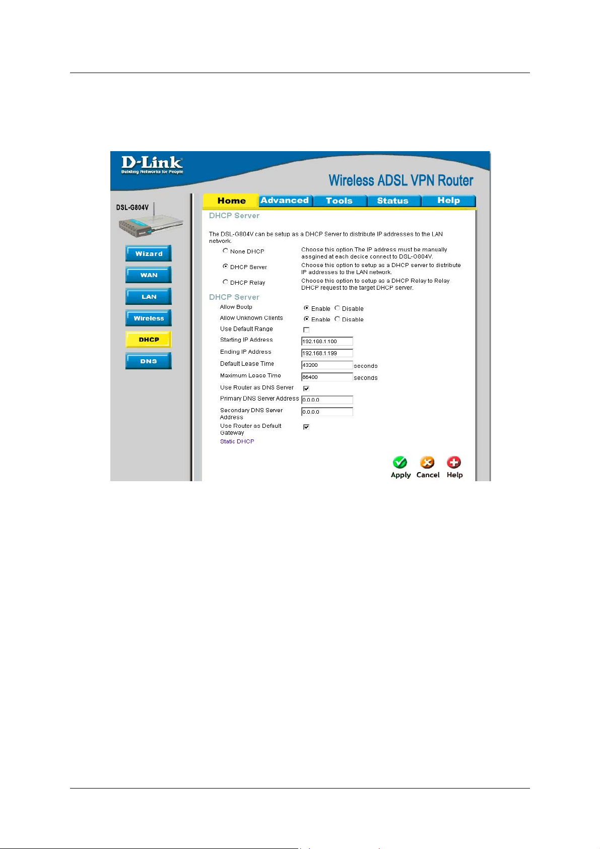
DHCP Server
DHCP stands for Dynamic Host Control Protocol. The DHCP protocol allows your router to dynamically assign
IP addresses to PCs on your network if they are configured to obtain IP addresses automatically.
Figure 3-13. Home – DHCP Server
None DHCP
The DHCP Server is disabled; you will need to manually assig n a fixed IP address to each PCs on your network ,
and set the default gateway for each PCs to the IP address of the router.
DHCP Server
You can configure parameters of the DHCP Server including the IP pool (starting IP address and ending IP
address to be allocated to PCs on your network), lease time for each assigned IP address (the period of time the
IP address assigned will be valid), DNS IP address and the gateway IP address. These details are sent to the
DHCP client (i.e. your PC) when it requests an IP address from the DHCP server. If you check “Use Router as a
DNS Server”, the ADSL Router will perform the domain name lookup, find the IP address from the outside
network automatically and forward it back to the requesting PC in the LAN (your Local Area Network).
30
Page 39

DSL-G804V Wireless ADSL Router User’s Guide
Static DHCP
It is used to allow DHCP server to assign the same IP to specific MAC address. This is useful when you setup
public servers (Web Server, FTP Server, for instance) inside LAN.
Figure 3-14. Home – DHCP Server (Static DHCP)
Parameter Description
Name
IP Address
MAC Address
Maximum Lease
Time
The name referencing the static IP assignment.
The IP address for the specific node in LAN.
The MAC address of the specific node in LAN.
The maximum time interval you allow the specific MAC user to obtain this IP
address.
DHCP Relay
You can enter the IP address of the DHCP server that will assign an IP address back to the DHCP client in the
LAN. Use this function only if advised to do so by your network administrator or ISP.
Figure 3-15. Home – DHCP Server (DHCP Relay)
31
Page 40

DSL-G804V Wireless ADSL Router User’s Guide
DNS Configuration
A Domain Name System (DNS) contains a mapping table for domain name and IP addresses. On the Internet,
every host has a unique and user-friendly name (domain name) such as www.helloworld.com and an IP address.
An IP address is a 32-bit number in the form of xxx.xxx.xxx.xxx, for example 192.168.1.1. You can think of an I P
address as a telephone number for devices on the Internet, and the DNS will allow you to find the telephone
number for any particular domain name. As an IP Address is hard to remember, the DNS converts the friendly
name into its equivalent IP Address.
Figure 3-16. Home – DNS Configuration
You can obtain a Domain Name System (DNS) IP address automatically if your ISP has provided it when you
logon, check the Enable box. Usually when you choose PPPoE or PPPoA as your WAN - ISP protocol, the ISP
will provide the DNS IP address automatically. You may leave the configuration field blank.
Alternatively, your ISP may provide you with an IP address of their DNS. If this is the case, you must enter the
DNS IP address manually
32
Page 41

DSL-G804V Wireless ADSL Router User’s Guide
4
Advanced Router Management
Click the Advanced tab to access menus used to configure Virtual Server, Firewall, VPN, DDNS, Routing,
Wireless, ADSL, IP QoS, Time Schedule, Email, Device and IGMP.
Virtual Server
NAT can act as a “natural” Internet firewall; your router protects your network from being accessed by outside
users. When using NAT, all incoming connection attempts will point to your router, unless you specifically
create Virtual Server entries to forward those ports to a PC on your network.
TCP/IP and UDP types, which is port with 16-bit number that used to identify which the application p rogram
(usually a server) should be delivered from an incoming connections should be delivered to. Some ports have
numbers that are pre-assigned to them by the IANA (the Internet Assigned Numbers Authority), and these are
referred to as “well-known ports”. Servers follow the well-known port assignments so clients can locate them.
Virtual Sever utilizes protocol,
Note
Note
If you have disabled the NAT option in the WAN-ISP section, the Virtual Server function will
hence be invalid.
If the DHCP server option is enabled, you have to be very careful in assigning the IP addresses
of the virtual servers in order to avoid conflicts. The easiest way of configuring Virtual Servers is
to manually assign static IP address to each virtual server PC, with an address that does not fall
into the range of IP addresses that are to be issued by the DHCP server. You can configure the
virtual server IP address manually, but it must still be in the same subnet as the router.
33
Page 42

DSL-G804V Wireless ADSL Router User’s Guide
Add Virtual Server
When your router needs to allow outside users to access internal servers, e.g. a web server, FTP server, Email
server or game server, the router can act as a “virtual server”. You can set up a local server with a specific port
number for the service to use, e.g. web/HTTP (port 80), FTP (port 21), Telnet (port 23), SMTP (port 25), or
POP3 (port 110). When an incoming access request to the router for a specified port is received, it will be
forwarded to the corresponding internal server.
Figure 4-1. Virtual Server – Add Virtual Server
Parameter Description
Schedule
A self-defined time period to enable your virtual server. You may specify a
time schedule or Always on for the usage of this Virtual Server Entry. For
setup and detail, refer to Time Schedule section.
Name
Users-defined description to identify this entry or click
predefined rules.
Helper: 20 predefined rules are available. Click the Radio button to select the
rule; Application, Protocol and External/Redirect Ports will be filled after the
selection.
Protocol Type
It is the supported protocol for the virtual server. In addition to specifying the
port number to be used, you will also need to specify the protocol used. The
protocol used is determined by the particular application. Most applications will
use TCP or UDP.
Public Port(s)
The Port number on the Remote/WAN side used when accessing the virtual
server.
Private Port(s)
Private IP
The Port number used by the Local server in the LAN network.
The private IP in the LAN network that will be providing the virtual server
application.
Candidates: List all existing PCs connecting to the network. You may assign a
PC with IP address and MAC from this list.
Helper to select existing
Example:
34
Page 43

DSL-G804V Wireless ADSL Router User’s Guide
If you like to remote access your Router through the Web/HTTP at all time, you would need to enable port
number 80 (Web/HTTP) and map to Router’s IP Address. Then all incoming HTTP requests from you (Remote
side) will be forwarded to the Router with IP address of 192.168.0.1. Since port number 80 has already been
predefined, next to the Application click Helper. A list of predefined rules window will pop and select
HTTP_Sever.
Name: HTTP_Sever
Time Schedule: Always On
Protocol: tcp
External Port: 80-80
Redirect Port: 80-80
IP Address: 192.168.0.1
Edit DMZ Host
The DMZ Host is a local computer exposed to the Internet. When setting a particular internal IP address as the
DMZ Host, all incoming packets will be checked by the Firewall and NAT algorithms then passed to the DMZ
host, when a packet received does not use a port number used by any other Virtual Server entries.
This Local computer exposing to the Internet may face varies of security risks.
Note
Figure 4-2. Virtual Server – Edit DMZ Host
Parameter Description
DMZ Host for
Disable or activate the DMZ function.
‘ipwan’ IP Interface
Private IP
Give a static IP address to the DMZ Host when Enabled radio button is
checked. Be aware that this IP will be exposed to the WAN/Internet.
Candidates: List all existing PCs connecting to the network. You may assign a
PC with IP address and MAC from this list.
Edit One-to-One NAT
35
Page 44

DSL-G804V Wireless ADSL Router User’s Guide
One-to-One NAT maps a specific private/local IP address to a global/public IP address. If you have multiple
public/WAN IP addresses from you ISP, you are eligible for One-to-One NAT to utilize these IP addresses.
Figure 4-3. Virtual Server –
Parameter Description
NAT Type
Select desired NAT type. As set in default setting, it disables the One-to-One
NAT function.
Global IP
Addresses
Subnet: The subnet of the public/WAN IP address given by your ISP. If your
ISP has provided this information, you may insert it here. Otherwise, use IP
Range method.
IP Range: The IP address range of your public/WAN IP addresses. For
example, IP: 192.168.1.1, end IP: 192.168.1.10.
Add Entry (Virtual
Server Entry)
You can create a new One-to-One NAT rule.
Schedule: A self-defined time period to enable your virtual server. You may
specify a time schedule or Always on for the usage of this Virtual Server Entry.
For setup and detail, refer to Time Schedule section..
Name: Users-defined description to identify this entry or click Helper to select
existing predefined rules.
Protocol Type: It is the supported protocol for the virtual server. In addition to
specifying the port number to be used, you will also need to specify the
protocol used. The protocol used is determined by the particular application.
Public Port(s): The Port number on the Remote/WAN side used when
accessing the virtual server.
Private Port(s): The Port number used by the Local server in the LAN network
Private IP: The private IP in the LAN network which will be providing the
virtual server application.
Edit One-to-One NAT
36
Page 45

DSL-G804V Wireless ADSL Router User’s Guide
Firewall
Firewall is used to allow or deny traffic from passing through your local network. If Firewall is enabled, the
Packet Filter will be used to filter packets based-on Applications (Port) or IP ad dresses.
General Setting
VC, known as Virtual Circuit or Virtual Channel, is a virtual path in which a communication session is
established. Check with your ISP for information.
Figure 4-4. Firewall – General Setting
Note
Parameter Description
Security
Policy
Block WAN Request
Click Apply and then click Next to process.
Any remote user who is attempting to perform this action may result in blocki ng all the accesses
to configure and manage of the device from the Internet.
Disable or activate the Firewall function.
There are four options when you enable the Firewall, they are:
All blocked/User-defined: no pre-defined port or address filter rules by
default, meaning that all inbound (Internet to LAN) and outbound (LAN to
Internet) packets will be blocked. Users have to add their own filter rules for
further access to the Internet.
High/Medium/Low security level: the predefined port filter rules for High,
Medium and Low security are displayed in Port Filters of Packet Filter.
This is a stand-alone function and not related to whether security is enabled or
disabled. Mostly it is for preventing any scan tools from WAN site initiated by a
hacker.
37
Page 46

DSL-G804V Wireless ADSL Router User’s Guide
Packet Filter
This function is only available when the Firewall is enabled and one of these four security levels is chosen (All
blocked, High, Medium and Low). The predefined port filter rules in the Packet Filter must modify accordingly
to the level of Firewall, which is selected. See Table1: Predefined Port Filter for more detailed information.
38
Page 47

DSL-G804V Wireless ADSL Router User’s Guide
Example: Predefined Port Filters Rules
The predefined port filter rules for High, Medium and Low security levels are listed. See Table 1.
Firewall – All Blocked/User-defined, you must define and create the port filter rules yourself.
Note
No predefined rule is set.
Table 1: Predefined Port Filter
Application Protocol
Port Number Firewall - High Firewall - Medium Firewall – Low
39
Page 48

DSL-G804V Wireless ADSL Router User’s Guide
HTTP(80) TCP(6) 80 80
DNS (53) UDP(17) 53 53 NO
DNS (53) TCP(6) 53 53 NO
Start End Inbound Outbound Inbound Outbound Inbound Outbound
NO
YES
YES
YES
NO
NO
NO
FTP(21) TCP(6) 21 21 NO NO NO
Telnet(23) TCP(6) 23 23 NO NO NO
SMTP(25) TCP(6) 25 25 NO
POP3(110) TCP(6) 110 110 NO
YES
YES
NO
NO
NEWS(119) TCP(6) 119 119 NO NO NO
RealAudio
UDP(17) 7070 7070 NO NO
YES YES
(7070)
YES
YES
YES
YES
YES
YES
YES
YES
NO
YES
YES YES
YES YES
NO
NO
NO
NO
NO
YES
YES
YES
YES
YES
YES YES
PING ICMP(1) N/A N/A NO
YES
NO
H.323(1720) TCP(6) 1720 1720 NO NO NO
T.120(1503) TCP(6) 1503 1503 NO NO NO
SSH(22) TCP(6) 22 22 NO NO NO
NTP(123) UDP(17) 123 123 NO
YES
NO
HTTPS(443) TCP(6) 443 443 NO NO NO
Inbound: Internet to LAN
Outbound: LAN to Internet.
Packet Filter - Add TCP/UDP Filter
YES
YES
YES
YES
YES
YES
NO
YES
YES YES
YES YES
YES YES
NO
NO
YES
YES
40
Page 49
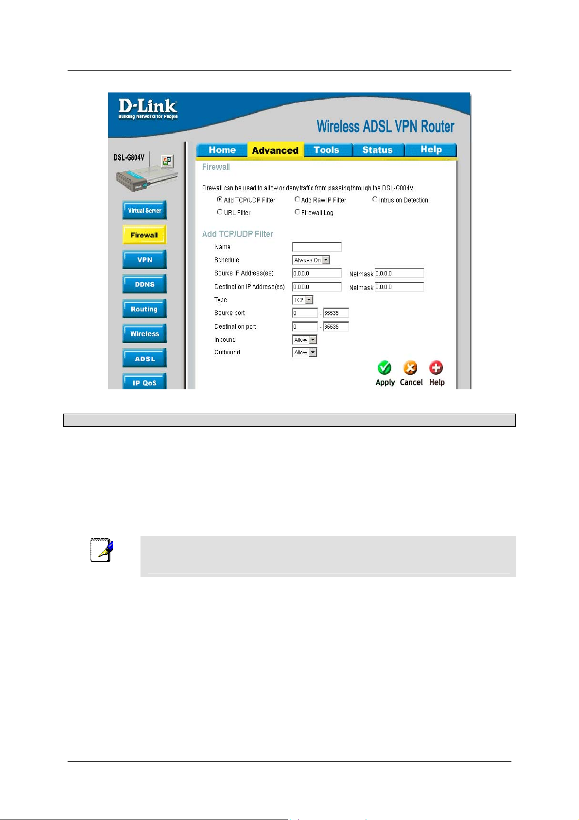
DSL-G804V Wireless ADSL Router User’s Guide
Figure 4-5. Firewall – Add TCP/UDP Filter
Parameter Description
Name
Schedule
A user defined name for identifying the rule.
It is self-defined time period. You may specify a time schedule for your
prioritization policy. For setup and detail, refer to Time Schedule section.
Sources IP
Adderss(es) /
Destination IP
Address(es)
This is the Address-Filter used to allow or block traffic to/from particular IP
address (es). Selecting the Subnet Mask of the IP address range you wish to
allow/block the traffic to or form; set IP address and Subnet Mask to 0.0.0.0 to
inactive the Address-Filter rule.
To block access, to / from a single IP address, enter that IP address as the Host IP Address and
Note
use a Host Subnet Mask of “255.255.255.255”.
Source port /
Destination port
This is the Address-Filter used to allow or block traffic to/from particular IP
address(es). Selecting the Subnet Mask of the IP address range you wish to
allow/block the traffic to or form; set IP address and Subnet Mask to 0.0.0.0 to
inactive the Address-Filter rule.
Inbound / Outbound
Select Allow or Block the access to the Internet (“Outbound”) or from the
Internet (“Inbound”).
Packet Filter - Add Raw Filter
41
Page 50

DSL-G804V Wireless ADSL Router User’s Guide
Figure 4-6. Firewall – Add Raw Filter
Parameter Description
Name
Schedule
A user defined name for identifying the rule.
It is self-defined time period. You may specify a time schedule for your
prioritization policy. For setup and detail, refer to Time Schedule section.
Protocol Number
Inbound / Outbound
Insert the port number, i.e. GRE 47.
Select Allow or Block the access to the Internet (“Outbound”) or from the
Internet (“Inbound”).
Configuring Packet Filter:
42
Page 51
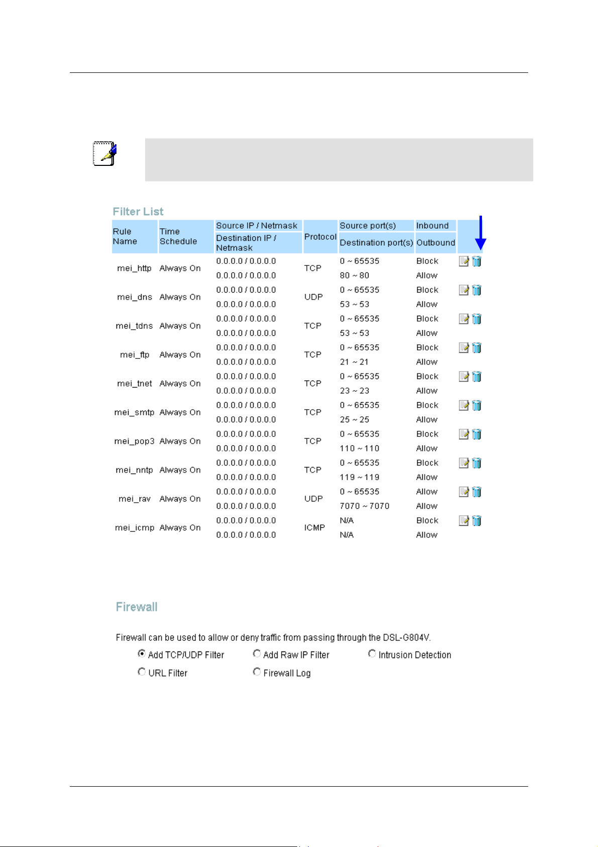
DSL-G804V Wireless ADSL Router User’s Guide
1. Click Port Filters. You will then be presented with the predefined port filter rules screen (in this case for
the low security level), shown below:
Note
you add a filter on your own.
Click Delete
You may click Edit the predefined rule instead of Delete it. This is an example to show to how
2. Click Delete to delete the existing HTTP rule.
3. Click Add TCP/UDP Filter.
Input the Rule Name, Time Schedule, Source/Destination IP, Type, Source/Destination Port, Inbound and
Outbound.
Intrusion Detection.
43
Page 52

DSL-G804V Wireless ADSL Router User’s Guide
The router’s Intrusion Detection System (IDS) is used to detect hacker attacks and intrusion attempts from the
Internet. If the IDS function of the firewall is enabled, inbound packets are filtered and blocked depending on
whether they are detected as possible hacker attacks, intrusion attempts or other connections that the router
determines to be suspicious.
Figure 4-7. Firewall – Intrusion Detection
Parameter Description
Intrusion Detection
Victim Protection
Disable or activate this function.
This is the duration for blocking Smurf attacks.
Block Duration
(seconds)
Scan Attack Block
Duration (seconds)
This is the duration for blocking hosts that attempt a possible Scan attack.
Scan attack types include X’mas scan, IMAP SYN/FIN scan and similar
attempts
DOS Attack Block
Duration (seconds)
This is the duration for blocking hosts that attempt a possible Denial of Service
(DoS) attack. Possible DoS attacks this attempts to block include Ascend Kill
and WinNuke.
Maximum TCP
Open Handshaking
This is a threshold value to decide whether a SYN Flood attempt is occurring
or not.
Count (per second))
Maximum Ping
Count (per second)
Maximum ICMP
This is a threshold value to decide whether an ICMP Echo Storm is occurring
or not.
This is a threshold to decide whether an ICMP flood is occurring or not.
Count (per second)
Clear Blocklist
If the router detects a possible attack, the source IP or destination IP address
will be added to the Blacklist. Any further attempts using this IP address will be
blocked for the time period specified as the Block Duration. Click it to remove
the detected IP addresses from the blocklist.
44
Page 53
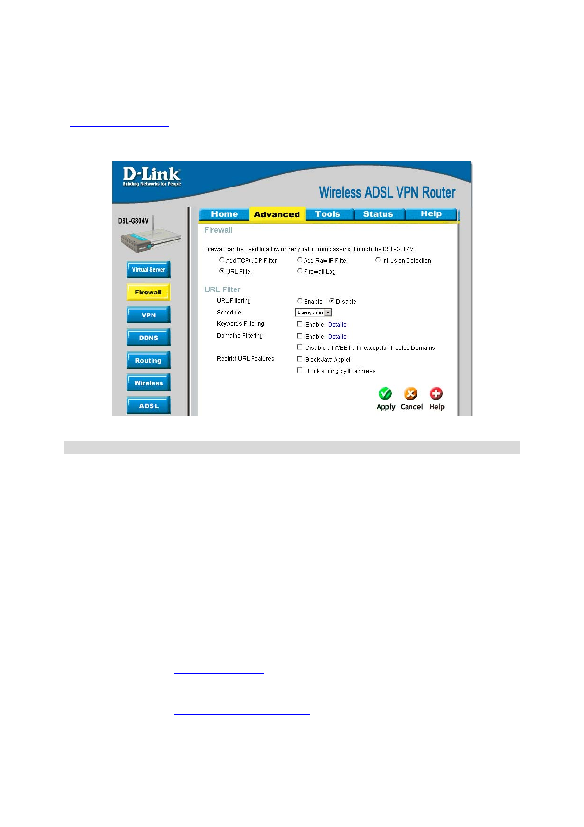
DSL-G804V Wireless ADSL Router User’s Guide
URL Filter
URL (Uniform Resource Locator – e.g. an address in the form of
http://www.abcde.com or
http://www.example.com) filter rules allow you to prevent users on your network from accessing particular
websites by their URL. There are no predefined URL filter rules; you can add filter rules to meet your
requirements.
Parameter Description
URL Filtering
Schedule
Disable or activate this function.
It is self-defined time period. Check Disable radio button to inactivate the URL
Filtering function, or keep the URL Filtering as Always on. You may also
specify a time schedule for your prioritization policy. For setup and detail, refer
to Time Schedule section.
Keywords Filtering
Allows blocking by specific keywords within a particular URL rather than
having to specify a complete URL (e.g. to block any image called
“advertisement.gif”). When enabled, your specified keywords list will be
checked to see if any keywords are present in URLs accessed to determine if
the connection attempt should be blocked.
Domain Filtering
This function checks the domain name only, not the IP address, in URLs
accessed against your list of domains to block or allow. If it is matched, the
URL request will be sent (Trusted) or dropped (Forbidden). For this function to
be activated, both Enable and Disable all WEB traffic except for Trusted
Domain must be checked.
Restrict URL
Features
This function enhances the restriction to your URL rules.
Block Java Applet: This function can block Web content which includes the
Java Applet. It is to prevent someone who wants to damage your system via
standard HTTP.
Figure 4-8. Firewall – URL Filter
Block surfing by IP address: Preventing someone who uses the IP address
as URL for skipping Domain Filtering function. Activate only if Domain
Filtering is Enable.
45
Page 54
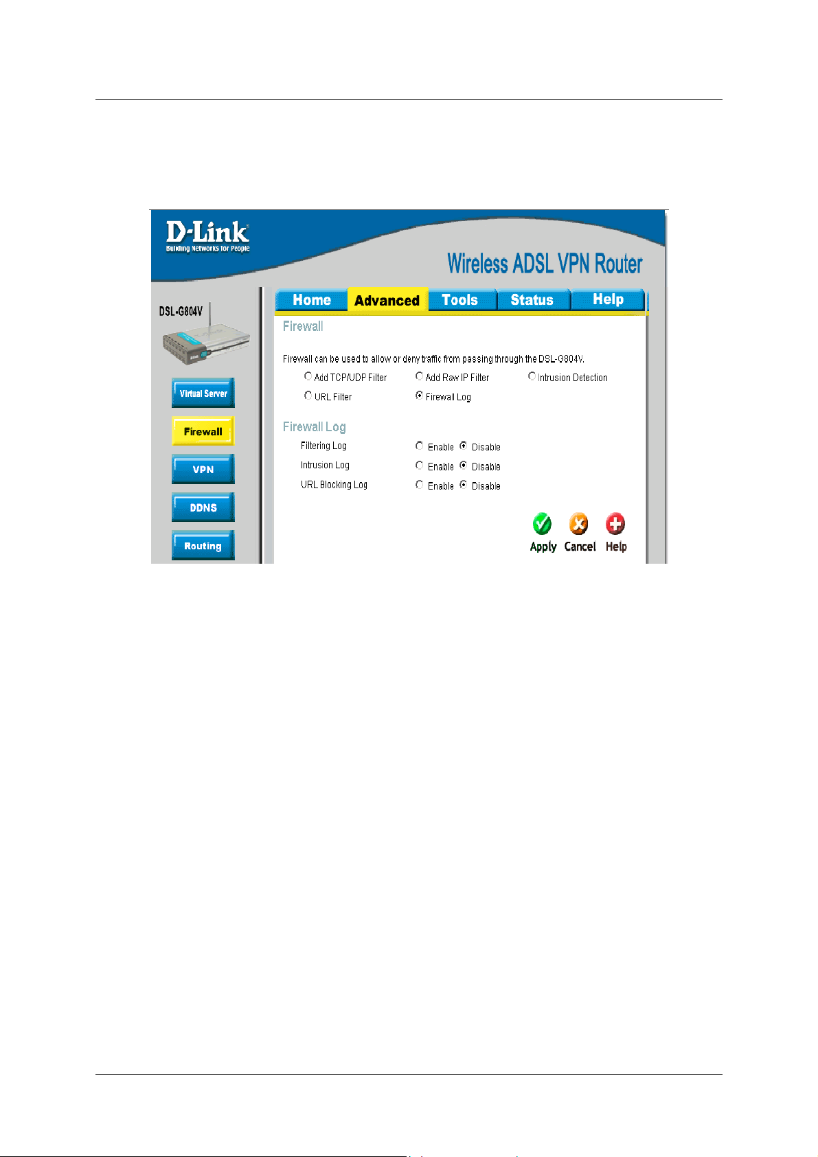
DSL-G804V Wireless ADSL Router User’s Guide
Firewall Log
Firewall Log displays log information of any unexpected action with your firewall settings.
Check the Enable box to activate the logs.
Log information can be seen in the Status – Event Log after enabling.
Figure 4-9. Firewall – Firewall Log
46
Page 55

DSL-G804V Wireless ADSL Router User’s Guide
VPN
Virtual Private Networks is ways to establish secured communication tunnels to an organization’s network via
the Internet. Each type of VPN has its form of encryption. In the router which supports three main types of
VPN (Virtual Private Network), PPTP, IPSec and L2TP.
PPTP (Point-to-Point Tunneling Protocol)
There are two types of PPTP VPN supported: Remote Access and LAN-to-LAN.
PPTP – Remote Access
Figure 4-10. VPN – PPTP
Figure 4-11. VPN – PPTP Remote Access
47
Page 56

DSL-G804V Wireless ADSL Router User’s Guide
Parameter Description
Connection Name
Service Type
IP Address
Account
Configuration
Username
Password
Authentication Type
Idle Timeout (in
minutes)
Activate as default
route
A user-de fined name for the connection (e.g. “connection to office”).
Check Dial Out if you want your router to operate as a client (connecting to a
remote VPN server, e.g. your office server), check Dial In operates as a VPN
server by assigning IP address to dial-in user.
If uses Dial Out as a client to the remote server, enter Server IP Address of
the remote server IP address.
If uses Dial In as a server, enter a Private IP Address Assigned to the Dial-
in user.
If you are a Dial-Out user (client), enter the username provided by your Host.
If you are a Dial-In user (server), enter your own username.
If you are a Dial-Out user (client), enter the password provided by your Host.
If you are a Dial-In user (server), enter your own password.
Default is Auto if you want the router to determine the authentication type to
use, or else manually specify CHAP (Challenge Handshake Authentication
Protocol) or PAP (Password Authentication Protocol) if you know which type
the server is using (when acting as a client), or else the authentication type
you want clients connecting to you to use (when acting as a server). When
using PAP, the password is sent unencrypted, whilst CHAP encrypts the
password before sending, and also allows for challenges at different periods to
ensure that t he client has not been replaced by an intruder.
Auto-disconnect the VPN connection when there is no activity on the
connection for a predetermined period of time. 0 means this connection is
always on.
Enables the default route.
Encryption Setting
Data Encryption
Key Length
Mode
Data sent over the VPN connection can be encrypted by an MPPE algorithm.
Default is Auto, so that this setting is negotiated when establishing a
connection, or else you can manually Enable or Disable encryption.
The data can be encrypted by MPPE algorithm with 40 bits or 128 bits. Default
is Auto, it is negotiated when establishing a connection. 128 bit keys provide
stronger encryption than 40 bit keys.
You may select Stateful or Stateless mode. The key will be changed every
256 packets when you select Stateful mode. If you select Stateless mode, the
key will be changed in each packet.
48
Page 57
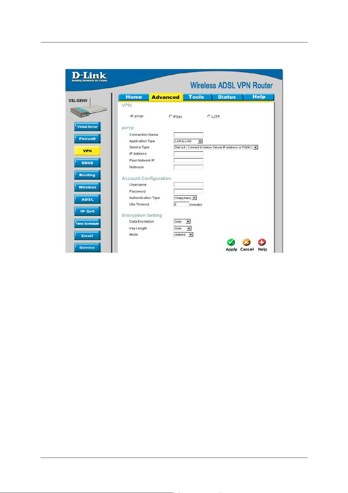
PPTP – LAN-to-LAN
DSL-G804V Wireless ADSL Router User’s Guide
Figure 4-12. VPN – PPTP LAN to LAN
49
Page 58

DSL-G804V Wireless ADSL Router User’s Guide
Parameter Description
Connection Name
Service Type
IP Address
Peer Network
Net Mask
Account
Configuration
Username
Password
Authentication Type
Idle Timeout (in
minutes)
Encryption Setting
A user-defined name for the connection (e.g. “connection to office”).
Check Dial Out if you want your router to operate as a client (connecting to a
remote VPN server, e.g. your office server), check Dial In operates as a VPN
server by assigning IP address to dial-in user.
If uses Dial Out as a client to the remote server, enter Server IP Address of
the remote server IP address.
Enter Peer network IP address.
Enter the subnet mask of peer network based on the Peer Network IP setting.
If uses Dial In as a server, enter a Private IP Address Assigned to the Dial-
in user.
If you are a Dial-Out user (client), enter the username provided by your Host.
If you are a Dial-In user (server), enter your own username.
If you are a Dial-Out user (client), enter the password provided by your Host.
If you are a Dial-In user (server), enter your own password.
Default is Auto if you want the router to determine the authentication type to
use, or else manually specify CHAP (Challenge Handshake Authentication
Protocol) or PAP (Password Authentication Protocol) if you know which type
the server is using (when acting as a client), or else the authentication type
you want clients connecting to you to use (when acting as a server). When
using PAP, the password is sent unencrypted, whilst CHAP encrypts the
password before sending, and also allows for challenges at different periods to
ensure that the client has not been replaced by an intruder.
Auto-disconnect the VPN connection when there is no activity on the
connection for a predetermined period of time. 0 means this connection is
always on.
Data Encryption
Key Length
Mode
Data sent over the VPN connection can be encrypted by an MPPE algorithm.
Default is Auto, so that this setting is negotiated when establishing a
connection, or else you can manually Enable or Disable encryption.
The data can be encrypted by MPPE algorithm with 40 bits or 128 bits. Default
is Auto, it is negotiated when establishing a connection. 128 bit keys provide
stronger encryption than 40 bit keys.
You may select Stateful or Stateless mode. The key will be changed every
256 packets when you select Stateful mode. If you select Stateless mode, the
key will be changed in each packet.
50
Page 59

DSL-G804V Wireless ADSL Router User’s Guide
IPSec (IP Security Protocol)
Parameter Description
Connection Name
Local Network
A user-defined name for the connection. No digital number is allowed.
Set the Single address, subnet or IP range of the local network.
IP Address: The IP address of the local host.
Netmask: The subnet of the local network. For example, IP: 192.168.0.0 with
netmask 255.255.255.0 specifies one class C subnet starting from 192.168.0.1
(i.e. 192.168.1.1 through to 192.168.1.254)
End IP:
The IP address range of the local network. For example, IP:
192.168.0.1, end IP: 192.168.0.10
Remote Secure
Gateway IP
Remote Network
The IP address or hostname of the remote VPN device that is connected and
establishes a VPN tunnel.
Set the Single address, subnet or IP range of the remote network.
IP Address: The IP address of the remote host.
Netmask:
with netmask 255.255.255.0 specifies one class C subnet starting from
192.168.1.1 (i.e. 192.168.1.1 through to 192.168.1.254).
End IP:
The IP address range of the remote network. For example, IP:
192.168.1.1, end IP: 192.168.1.10.
Proposal
Select the IPSec security method. There are two methods of checking the
authentication information, AH (authentication header) and ESP
(Encapsulating Security Payload). Use ESP for greater security so that data
will be encrypted and authenticated. Using AH data will be authenticated but
not encrypted.
Figure 4-13. VPN – IPSec
The subnet of the remote network. For example, IP: 192.168.1.0
51
Page 60

DSL-G804V Wireless ADSL Router User’s Guide
Parameter Description
Authentication Type
Authentication establishes the integrity of the datagram and ensures it is not
tampered with in transmit. There are three options, Message Digest 5 (MD5),
Secure Hash Algorithm (SHA1) or NONE. SHA-1 is more resistant to bruteforce attacks than MD5, however it is slower.
Encryption
Select the encryption method from the pull-down menu. There are several
options, DES, 3DES, AES (128, 192 and 256) and NULL. NULL means it is a
tunnel only with no encryption. 3DES and AES are more powerful but increase
latency.
Perfect Forward
Secrecy
Choose whether to enable PFS using Diffie-Hellman public-key cryptography
to change encryption keys during the second phase of VPN negotiation. This
function will provide better security, but extends the VPN negotiation time.
Diffie-Hellman is a public-key cryptography protocol that allows two parties to
establish a shared secret over an unsecured communication channel (i.e. over
the Internet). There are three modes, MODP 768-bit, MODP 1024-bit and
MODP 1536-bit. MODP stands for Modular Exponentiation Groups.
Pre-shared Key
This is for the Internet Key Exchange (IKE) protocol, a string from 4 to 128
characters. Both sides should use the same key. IKE is used to establish a
shared security policy and authenticated keys for services (such as IPSec) that
require a key. Before any IPSec traffic can be passed, each router must be
able to verify the identity of its peer. This can be done by manually entering the
pre-shared key into both sides (router or hosts).
Click Apply to save the setting.
52
Page 61

DSL-G804V Wireless ADSL Router User’s Guide
IPSec - Advanced Option (In the VPN/IPSec List, select a IPSec rule then click the Edit to modify)
This function is only available after completed creating an IPSec account. Click Advanced Option to change the
following settings:
Figure 4-14. VPN – IPSec Advanced Option
Parameter Description
IKE Mode
Select IKE (Internet Key Exchange) mode to Main mode or Aggressive mode.
IKE provides secured key generation and key management.
IKE Proposal
Hash Function
It is a Message Digest algorithm which coverts any length of a message into a
unique set of bits. It is widely used MD5 (Message Digest) and SHA-1
(Secure Hash Algorithm) algorithms.
Encryption
Select the encryption method from the pull-down menu. There are several
options, DES, 3DES and AES(128, 192 and 256). 3DES and AES are more
powerful but increase latency.
Diffie-Hellman
Group
Local ID
Type
Content
It is a public-key cryptography protocol that allows two parties to establish a
shared secret over an unsecured communication channel (i.e. over the
Internet). There are three modes, MODP 768-bit, MODP 1024-bit and MODP
1536-bit. MODP stands for Modular Exponentiation Groups.
Specify Local ID type.
Input Local ID’s information, either email or domain name.
53
Page 62

DSL-G804V Wireless ADSL Router User’s Guide
Parameter Description
Remote ID
Type
Content
SA Lifetime
Phase 1 (IKE)
Phase 2 (IPSec)
A short SA time increases security by forcing the two parties to update the keys.
Note
PING for keepalive
PING to the IP
Interval
However, every time the VPN tunnel re-negotiates, access through the tunnel will be
temporarily disconnected.
xxx.xxx.xxx.xxx (A valid IP
xxx.xxx.xxx.xxx(A valid IP
Disconnection Time
after no traffic
Reconnection Time
Specify Remote ID type.
Input remote ID’s information, either email or domain name.
To issue an initial connection request for a new VPN tunnel. The range can be
from 5 to 15,000 minutes.
To negotiate and establish secure authentication. The range can be from 5 to
15,000 minutes.
It is used to detect IPSec tunnel connection failure. Connection failure is
defined as abort or in NO response state. In such event Ping to Keepalive
takes proper action to ensure the connection quality of IPSec.
It is able to IP Ping the remote PC with the specified IP address and alert
when the connection fails. Once alter message is received, Router will drop
this tunnel connection. Re-establish of this connection is required. 0.0.0.0
which disables the function.
This sets the time interval between Pings to the IP function to monitor the
connection status. Time interval can be set from 0 to 3600 second, 0 second
disables the function.
Ping to the IP Internal (sec) Ping to the IP Action
0.0.0.0 0 No
0.0.0.0 2000 No
Address)
Address)
It is the NO Response time clock. When no traffic stage time is beyond the
Disconnection time set, Router will automatically halt the tunnel connection
and re-establish it base on the Reconnection Time set. 180 seconds is
minimum time interval for this function.
It is the reconnecting time interval after NO TRAFFIC is initiated. Default
setting is 15 minutes; 3 minutes is minimum time interval for this function.
0 No
2000 Yes, activate it in every
2000 second.
54
Page 63

DSL-G804V Wireless ADSL Router User’s Guide
L2TP (Layer2 Tunneling Protocol)
There are two types of L2TP VPN supported: Remote Access and LAN-to-LAN.
Figure 4-15. VPN – L2TP
55
Page 64

L2TP – Remote Access
DSL-G804V Wireless ADSL Router User’s Guide
Figure 4-16. VPN – L2TP Remote Access
Parameter Description
Connection Name
Service Type
A user-defined name for the connection.
Check Dial Out if you want your router to operate as a client (connecting to a
remote VPN server, e.g. your office server), check Dial In operates as a VPN
server by assigning IP addr ess to dial-in user.
IP Address
If uses Dial Out as a client to the remote server, enter Server IP Address of
the remote server IP address.
If uses Dial In as a server, enter a Private IP Address Assigned to the Dial-
in user.
Account
Configuration
Username
If you are a Dial-Out user (client), enter the username provided by your Host.
If you are a Dial-In user (server), enter your own username.
Password
If you are a Dial-Out user (client), enter the password provided by your Host.
If you are a Dial-In user (server), enter your own password.
56
Page 65

DSL-G804V Wireless ADSL Router User’s Guide
Parameter Description
Authentication Type
Idle Timeout (in
minutes)
Activate as default
route
Enable IPSec
When Enable IPSec
is activated
Authentication
Encryption
Perfect Forward
Secrecy
Pre-shared Key
When Enable
Tunnel
Authentication is
activated
Secret
Remote Host Name
Local Host Name
Default is Auto if you want the router to determine the authentication type to
use, or else manually specify CHAP (Challenge Handshake Authentication
Protocol) or PAP (Password Authentication Protocol) if you know which type
the server is using (when acting as a client), or else the authentication type
you want clients connecting to you to use (when acting as a server). When
using PAP, the password is sent unencrypted, whilst CHAP encrypts the
password before sending, and also allows for challenges at different periods to
ensure that the client has not been replaced by an intruder.
Auto-disconnect the VPN connection when there is no activity on the
connection for a predetermined period of time. 0 means this connection is
always on.
Enables the default route.
Enable for enhancing your LT2P VPN security. Check the box to active these
functions.
Authentication establishes the integrity of the datagram and ensures it is not
tampered with in transmit. There are three options, Message Digest 5 (MD5),
Secure Hash Algorithm (SHA1) or NONE. SHA-1 is more resistant to bruteforce attacks than MD5, however it is slower.
Select the encryption method from the pull-down menu. There are several
options, DES, 3DES, AES(128, 192 and 256) and NULL. NULL means it is a
tunnel only with no encryption. 3DES and AES are more powerful but increase
latency.
Choose whether to enable PFS using Diffie-Hellman public-key cryptography
to change encryption keys during the second phase of VPN negotiation. This
function will provide better security, but extends the VPN negotiation time.
Diffie-Hellman is a public-key cryptography protocol that allows two parties to
establish a shared secret over an unsecured communication channel (i.e. over
the Internet). There are three modes, MODP 768-bit, MODP 1024-bit and
MODP 1536-bit. MODP stands for Modular Exponentiation Groups.
This is for the Internet Key Exchange (IKE) protocol, a string from 4 to 128
characters. Both sides should use the same key. IKE is used to establish a
shared security policy and authenticated keys for services (such as IPSec) that
require a key. Before any IPSec traffic can be passed, each router must be
able to verify the identity of its peer. This can be done by manually entering the
pre-shared key into both sides (router or hosts).
The secure password length should be 16 characters which may include
numbers and characters.
(Option) Enter hostname of remote VPN device. It is a tunnel identifier from
the Remote VPN device matches with the Remote hostname provided. If
remote hostname matches, tunnel will be connected; otherwise, it will be
dropped.
Cautious: This is only when the router performs as a VPN server. This option
should be used by advanced users only.
(Option) Enter hostname of Local VPN device that is connected / establishes a
VPN tunnel. As default, Router’s default Hostname is home.gateway.
57
Page 66

L2TP – LAN-to-LAN
DSL-G804V Wireless ADSL Router User’s Guide
Figure 4-17. VPN – L2TP LAN to LAN
Parameter Description
Connection Name
Service Type
A user-defined name for the connection (e.g. “connection to office”).
Check Dial Out if you want your router to operate as a client (connecting to a
remote VPN server, e.g. your office server), check Dial In operates as a VPN
server by assigning IP address to dial-in user.
IP Address
If uses Dial Out as a client to the remote server, enter Server IP Address of
the remote server IP address.
Peer Network
Net Mask
Enter Peer network IP address.
Enter the subnet mask of peer network based on the Peer Network IP setting.
If uses Dial In as a server, enter a Private IP Address Assigned to the Dial-
in user.
Account
Configuration
Username
If you are a Dial-Out user (client), enter the username provided by your Host.
If you are a Dial-In user (server), enter your own username.
Password
If you are a Dial-Out user (client), enter the password provided by your Host.
If you are a Dial-In user (server), enter your own password.
58
Page 67

DSL-G804V Wireless ADSL Router User’s Guide
Parameter Description
Authentication Type
Idle Timeout (in
minutes)
Enable IPSec
When Enable IPSec
is activated
Authentication
Encryption
Perfect Forward
Secrecy
Pre-shared Key
When Enable
Tunnel
Authentication is
activated
Secret
Remote Host Name
Local Host Name
Default is Auto if you want the router to determine the authentication type to
use, or else manually specify CHAP (Challenge Handshake Authentication
Protocol) or PAP (Password Authentication Protocol) if you know which type
the server is using (when acting as a client), or else the authentication type
you want clients connecting to you to use (when acting as a server). When
using PAP, the password is sent unencrypted, whilst CHAP encrypts the
password before sending, and also allows for challenges at different periods to
ensure that the client has not been replaced by an intruder.
Auto-disconnect the VPN connection when there is no activity on the
connection for a predetermined period of time. 0 means this connection is
always on.
Enable for enhancing your LT2P VPN security. Check the box to active these
functions.
Authentication establishes the integrity of the datagram and ensures it is not
tampered with in transmit. There are three options, Message Digest 5 (MD5),
Secure Hash Algorithm (SHA1) or NONE. SHA-1 is more resistant to bruteforce attacks than MD5, however it is slower.
Select the encryption method from the pull-down menu. There are several
options, DES, 3DES, AES(128, 192 and 256) and NULL. NULL means it is a
tunnel only with no encryption. 3DES and AES are more powerful but increase
latency.
Choose whether to enable PFS using Diffie-Hellman public-key cryptography
to change encryption keys during the second phase of VPN negotiation. This
function will provide better security, but extends the VPN negotiation time.
Diffie-Hellman is a public-key cryptography protocol that allows two parties to
establish a shared secret over an unsecured communication channel (i.e. over
the Internet). There are three modes, MODP 768-bit, MODP 1024-bit and
MODP 1536-bit. MODP stands for Modular Exponentiation Groups.
This is for the Internet Key Exchange (IKE) protocol, a string from 4 to 128
characters. Both sides should use the same key. IKE is used to establish a
shared security policy and authenticated keys for services (such as IPSec) that
require a key. Before any IPSec traffic can be passed, each router must be
able to verify the identity of its peer. This can be done by manually entering the
pre-shared key into both sides (router or hosts).
The secure password length should be 16 characters which may include
numbers and characters.
(Option) Enter hostname of remote VPN device. It is a tunnel identifier from
the Remote VPN device matches with the Remote hostname provided. If
remote hostname matches, tunnel will be connected; otherwise, it will be
dropped.
Cautious: This is only when the router performs as a VPN server. This option
should be used by advanced users only.
(Option) Enter hostname of Local VPN device that is connected / establishes a
VPN tunnel. As default, Router’s default Hostname is home.gateway.
59
Page 68

DSL-G804V Wireless ADSL Router User’s Guide
DDNS (Dynamic DNS)
The Dynamic DNS function allows you to alias a dynamic IP address to a static hostname, allowing users whose
ISP does not assign them a static IP address to use a domain name. This is especially useful for hosting servers
via your ADSL connection, so that anyone wishing to connect to you may use your domain name, rather than
having to use your dynamic IP address, which changes from time to time. This dynamic IP address is the WAN
IP address of the router, which is assigned to you by your ISP.
Parameter Description
Dynamic DNS
Dynamic DNS
Server
Wildcard
Host Name,
Username/Email
and Password/Key
Reflash Period
Disable or activate this feature.
Select the DDNS service you have established an account with.
When wildcard is enabled, a multiple matching to the Host Name will be point
to the same IP. Example: You have a host abce.no-ip.com. When the
wildcard enabled, xxxxx.abce.no-ip.com would point to the same IP address
as your abce.no-ip.com.
Enter your registered domain name and your username and password for this
service.
Set the time period between updates, for the Router to exchange information
with the DDNS server. In addition to updating periodically as per your settings,
the router will perform an update when your dynamic IP address changes.
Figure 4-18. DDNS
60
Page 69

DSL-G804V Wireless ADSL Router User’s Guide
Routing (Static Route)
Manually adds a static route to router routing table.
Figure 4-19. Routing (Static Route)
Parameter Description
Destination
Netmask
Gateway
Interface
Cost
This is the destination subnet IP address.
Subnet mask of the destination IP addresses based on above destination
subnet IP.
This is the gateway IP address to which packets are to be forwarded.
Select the interface through which packets are to be forwarded.
This is the same meaning as Hop. This should usually be left at 1.
61
Page 70

DSL-G804V Wireless ADSL Router User’s Guide
Wireless
Wireless Security and Wireless Client Filter parameter setup.
Wireless Security
The default mode of your wireless (access point) security is inactivated. You may choose either WPA or WEP
to protect your wireless network.
Wireless Security – WPA Pre-Shared Key
WPA Algorithms utilize the TKIP (Temporal Key Integrity Protocol), a stronger encryption method and
incorporates Message Code (MIC), to protect against hackers and security your wireless network.
Figure 4-20. Wireless Security – WPA Pre-Shared Key
Parameter Description
WPA Shared Key
Group Key Renewal
(in seconds)
Idle Timeout (in
seconds)
The key for network authentication. The input format is in character style and
key size should be in the range between 8 and 63 characters.
The period of renewal time for changing the security key automatically
between wireless client and Access Point (AP)
A Timeout value base on the case of no data traffic is send or received. If
Router detects no traffic in the wireless, it will start timing the clock and drop
the session as it reaches to the defined timeout value. New session will be reestablished after the old session. Minimum value is 120 seconds to Maximum
65535 seconds.
62
Page 71

DSL-G804V Wireless ADSL Router User’s Guide
Wireless Security – WEP
A WEP encryption algorithm is defined by a set of respective Key and Key String for the wireless network.
Figure 4-20. Wireless Security – WEP
Parameter Description
WEP Authentication
Three types of authentication are available, Open System, Shared Key and
Open System/ShareKey (Both).
Open System
long as the wireless client uses the same WEP key will be able to
communicate with router’s Access Point. The AP will remain visible to all
devices on the network.
Share Key:
use the same authentication and the Web Key to be able to communicate with
router’s Access Point.
Open System / Share Key (Both):
are employed. Wireless client may have selected open or share key setting
and still can get access to the Access point, only if correct WEP Key is
presented.
WEP Encryption
To prevent unauthorized wireless stations from accessing data transmitted
over the network, the router offers highly secure data encryption, known as
WEP. If you require high security for transmissions, there are two alternatives
to select from: WEP 64 and WEP 128. WEP 128 will offer increased security
over WEP 64.
Default Used WEP
Key (0-3)
Enter the key to encrypt wireless data. To allow encrypted data transmission,
the WEP Encryption Key values on all wireless stations must be the same as
the router. There are four keys for your selection. The input format is in HEX
style, 5 and 13 HEX codes are required for WEP64 and WEP128 respectively,
the separator is “-“. For example, using WEP64, 11-22-33-44-55 is a valid key,
whilst 1122334455 is invalid.
: Authentication is a void authentication; it is easy to use. As
It is more secure than the Open System. Wireless client must
With this setting both open and share key
63
Page 72
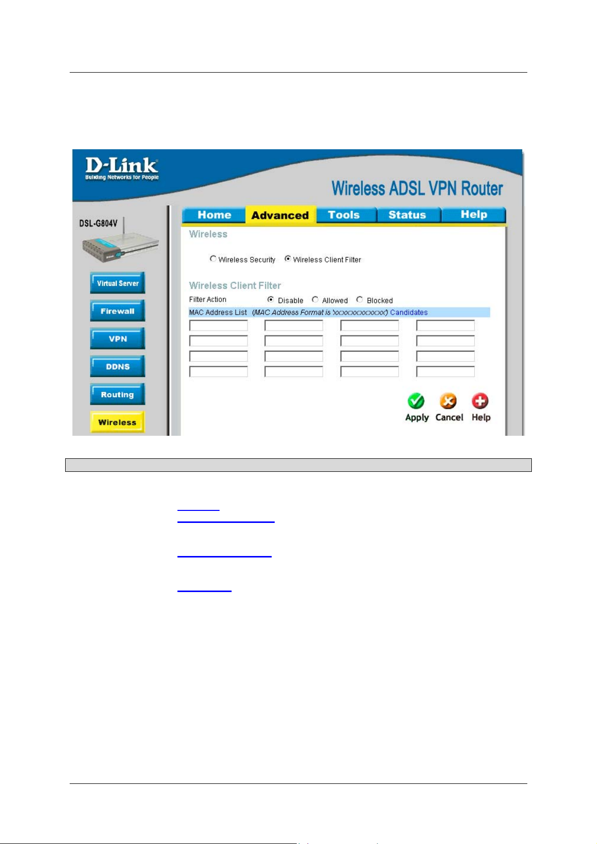
DSL-G804V Wireless ADSL Router User’s Guide
Wireless Client (MAC) Filter
The MAC Address supports up to 16 wireless network machines and helps you to manage your network control
to accept traffic from specific authorized machines or to restrict unwanted machine(s) to access your Wireless
LAN.
Figure 4-20. Wireless Client (MAC) Filter
Parameter Description
Filter Action
Select an appreciated filter action, Disable, Allowed (Whitelist), and Blocked
(Blacklist):
Disabled
Allowed (White List)
by insert the wireless AP MAC Address in the space provided. Make sure you
wireless AP MAC is listed.
Blocked (Blacklist)
wireless by insert the wireless AP MAC Address in the space provided. Make
sure your wireless AP MAC is NOT listed.
Candidates
AP MAC address which connecting to the router. You can easily by checking
the box next to the IP address to be blocked or allowed. Then Add to inse rt to
the Wireless Client Filter table. The maximum Wireless client is 16.
: This inactivates the Wireless Client Filter function.
: This authorizes specific device accessing your wireless
: check to prevent unwanted device accessing your
: Associated Wireless Clients displays a list of individual Wireless
64
Page 73
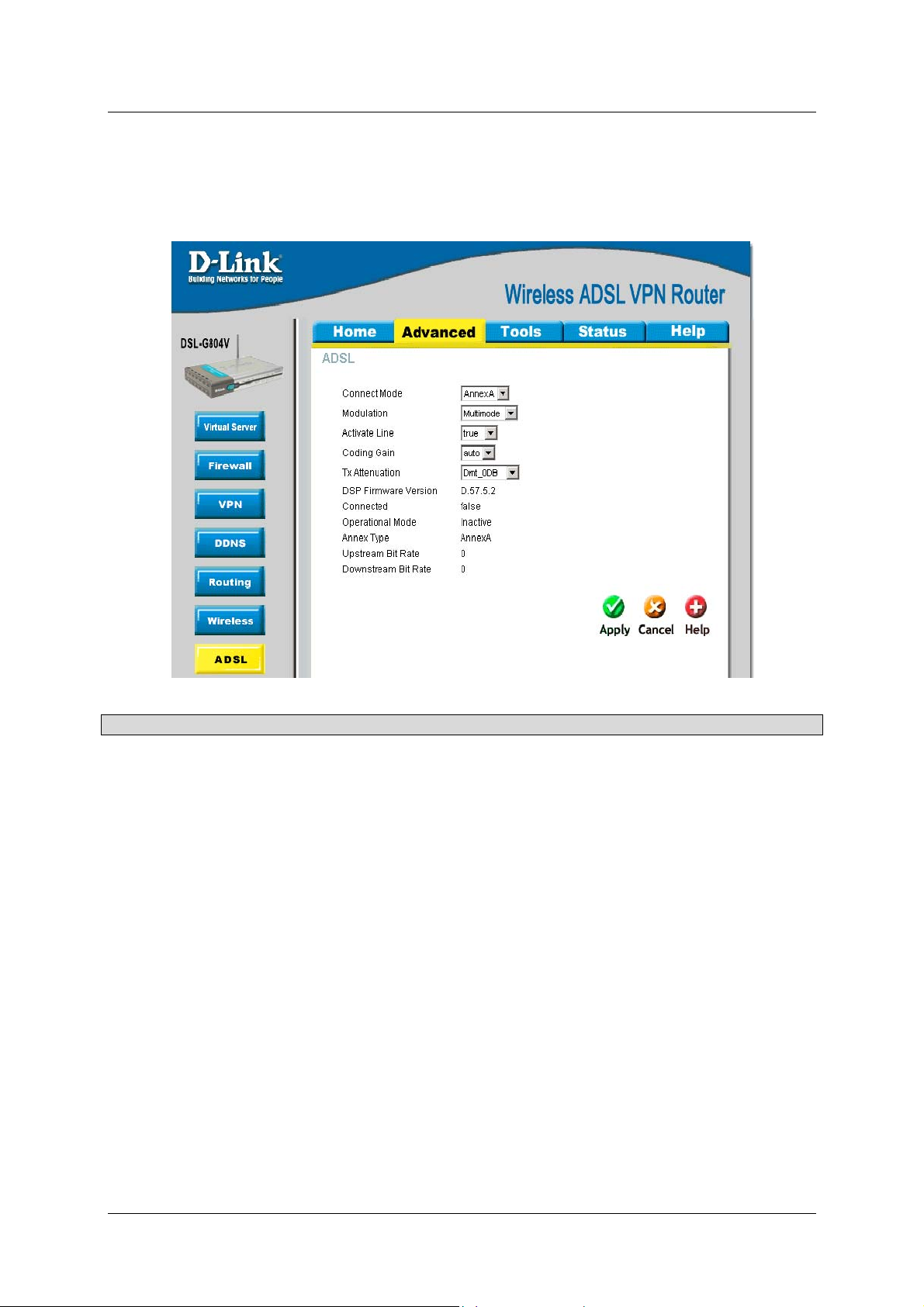
DSL-G804V Wireless ADSL Router User’s Guide
ADSL
This is the ADSL parameter adjustment and information section. The parameter is already being pre-defined and
not necessary to reconfigure if you do not understand this feature.
Parameter Description
Connect Mode
Modulation
Activate Line
Coding Gain
Tx Attenuation
DSP Firmware
Version
Connected
Operational Mode
Annex Type
Upstream Bit Rate
Connection line mode ADSL2/ADSL2+.
For ADSL connection, this mode will automatically detect your ADSL line code,
G.dmt, G.lite, and T1.413. But in some area, multimode cannot detect the
ADSL line code well. If it is the case, please adjust the ADSL line code to
G.dmt or T1.413 first. If it still fails, please try the other values such as ALCTL,
ADI, etc. For ADSL2 connection, this mode automatically detects your line
code to G.DMT.Bis.
Aborting (false) your ADSL line and making it active (true) again for taking
effect with setting of Connect Mode.
Configure the ADSL coding gain from 0 dB to 7dB, or automatic.
Setting ADSL transmission attenuation.
Firmware version of the Digital Signal Processor.
Display current ADSL line sync status.
ADSL Annex A, which works over a standard telephone line. Annex B, which
works over an ISDN line.
Display current upstream rate of your ADSL line.
Figure 4-23. ADSL
Downstream Bit
Rate
Display current downstream rate of your ADSL line.
65
Page 74

DSL-G804V Wireless ADSL Router User’s Guide
IP QoS
IP QoS function helps you to control your network traffic for each application from LAN (Ethernet and/or
Wireless) to WAN (Internet). It facilitates you to control the different quality and speed of through put for each
application when the system is running with full loading of upstream.
You can find three items under the QoS section: Prioritization and Outbound / Inbound IP Throttling
(bandwidth management).
Packet Prioritization
Prioritization categorizes in High (utilized 60% of the total ban dwidth), Normal (utilized 30% of the total
bandwidth), Low (utilized 10% of the total bandwidth).
Figure 4-24. IP QoS – Packet Prioritization
Parameter Description
Name
Schedule
Priority
Protocol
Source Port
Destination Port
A user-defined description to identify this new policy/application.
Check Disable radio button to inactivate the URL Filtering function, or keep
the URL Filtering as Always on. You may also specify a time schedule for
your prioritization policy. For setup and detail, refer to Time Schedule
section.
The priority given to each policy/application. Its default setting is set to High;
you may adjust this setting to fit your policy/application.
The name of supported protocol.
The source port of packets to be monitored.
The destination port of packets to be monitored.
66
Page 75

DSL-G804V Wireless ADSL Router User’s Guide
Parameter Description
Source IP Address
Range
Destination IP
Address Range
DSCP Marking
The source IP address or range of packets to be monitored.
The destination IP address or range of packets to be monitored.
Differentiated Services Code Point (DSCP), it is the first 6 bits in the ToS byte.
DSCP Marking allows users to classify traffic based on DSCP value and send
packets to next Router.
DSCP Mapping Table
DSCP Mapping Table
(Wireless) ADSL Router Standard DSCP
Disabled None
Best Effort Best Effort (000000)
Premium Express Forwarding (101110)
Gold service (L) Class 1, Gold (001010)
Gold service (M) Class 1, Silver (001100)
Gold service (H) Class 1, Bronze (001110)
Silver service (L) Class 2, Gold (010010)
Silver service (M) Class 2, Silver (010100)
Silver service (H) Class 2, Bronze (010110)
Bronze service (L) Class 3, Gold (011010)
Bronze service (M) Class 3, Silver (011100)
Bronze service (H) Class 3, Bronze (011110)
67
Page 76

DSL-G804V Wireless ADSL Router User’s Guide
Outbound Throttling (Packet from LAN to WAN)
IP Outbound Throttling allows you to limit the speed of IP traffic. The value entered will limit the speed of the
application that you set to the specified value’s multiple of 32kbps.
Figure 4-25. IP QoS – Outbound Throttling
Parameter Description
Name
Schedule
A user-defined description to identify this new policy/application.
Check Disable radio button to inactivate the URL Filtering function, or keep
the URL Filtering as Always on. You may also specify a time schedule for
your prioritization policy. For setup and detail, refer to Time Schedule
section.
Protocol
Source Port
Destination Port
Source IP Address
The name of supported protocol.
The source port of packets to be monitored.
The destination port of packets to be monitored.
The source IP address or range of packets to be monitored.
Range
Destination IP
The destination IP address or range of packets to be monitored.
Address Range
Rate Limit
The limited speed of outbound traffic.
68
Page 77

DSL-G804V Wireless ADSL Router User’s Guide
Inbound Throttling (Packet from WAN to LAN)
IP Inbound Throttling allows you to limit the speed of IP traffic. The value entered will limit the speed of the
application that you set to the specified value’s multiple of 32kbps.
Figure 4-26. IP QoS – Inbound Throttling
Parameter Description
Name
Schedule
Protocol
Source Port
Destination Port
Source IP Address
Range
Destination IP
Address Range
Rate Limit
A user-defined description to identify this new policy/application.
Check Disable radio button to inactivate the URL Filtering function, or keep
the URL Filtering as Always on. You may also specify a time schedule for
your prioritization policy. For setup and detail, refer to Time Schedule
section.
The name of supported protocol.
The source port of packets to be monitored.
The destination port of packets to be monitored.
The source IP address or range of packets to be monitored.
The destination IP address or range of packets to be monitored.
The limited speed of inbound traffic.
69
Page 78

DSL-G804V Wireless ADSL Router User’s Guide
Time Schedule
The Time Schedule supports up to 16 time slots which helps you to manage your Internet connection. It
correlates closely with router’s time, since router does not have a real time clock on board; it uses the Simple
Network Time Protocol (SNTP) to get the current time from an SNTP server from the Internet. Refer to Time
Zone for details. You router time should correspond with your local time. If the time is not set correctly, your
Time Schedule will not function properly.
Figure 4-27. Time Schedule
70
Page 79

Adding a Time Slot
DSL-G804V Wireless ADSL Router User’s Guide
Figure 4-28. Time Schedule – Adding a Time Slot
Parameter Description
ID
Name
Day
Start Time
End Time
Delete a Time Slot
Click Clear to delete the existing Time profile, i.e. erase the Day and back to default setting of Start Time / End
Time.
This is the index of the time slot.
A user-define description to identify this time portfolio.
The default is set from Monday through Friday. You may specify the days for
the schedule to be applied.
The default is set at 8:00 AM. You may specify the start time of the schedule.
The default is set at 18:00 (6:00PM). You may specify the end time of the
schedule.
71
Page 80

DSL-G804V Wireless ADSL Router User’s Guide
Check Email
Check Email allows you to have the router checks your POP3 mailbox for new Email messages. The Mail LED
on your router will light when it detects new messages waiting for download. You may also view the status o f
this function using the Status – Email Checking section of the web interface, which also provides details on the
number of new messages waiting. See the Status section of this manual for more information.
Parameter Description
Check Email
Account Name
Password
POP3 Mail Server
Period (minutes)
Automatically
Disable or activate the Email Checking function.
Enter the name (login) of the POP3 account you wish to check. Normally, it is
the text in your email address before the “@” symbol. If you have trouble with
it, please contact your ISP (Internet Service Provider).
Enter the account’s password.
Enter your (POP) mail server name. Your ISP or network administrator will be
able to supply you with this.
Set up a time interval to check your mail.
When the function is enabled, your ADSL router will connect to your ISP
automatically to check your emails if the Internet connection dropped. If your
ADSL service is charged by time online, you ought to be careful when using
this feature.
Figure 4-29. Check Email
72
Page 81

DSL-G804V Wireless ADSL Router User’s Guide
Device Management
The Device Management advanced configuration settings allow you to control your router’s security options and
device monitoring features.
Device Host Name
This is a given name to your router easily identify the router.
Embedded Web Server
Figure 4-30. Device Management – Host Name and Embedded Web Server
Parameter Description
HTTP Port
Management IP
Address
Expire to autologout
Example:
User A changes HTTP port number to 100, specifies their own IP address of 192.168.0.55, and sets the logout
time to be 100 seconds. The router will only allow User A access from the IP address 192.168.0.55 to logon to
the Web GUI by typing:
automatically logout User A. (192.168.0.1 is your router IP address).
This is the port number the router’s embedded web server (for web-based
configuration) will use. The default value is the standard HTTP port, 80. Users
may specify an alternative if, for example, they are running a web server on a
PC within their LAN. (Important: This setting will become effective after you
Save to flash and restart the router).
You may specify an IP address allowed to logon and access the router’s web
server. Setting the IP address to 0.0.0.0 will disable IP address restrictions,
allowing users to login from any IP address.
Specify a time frame for the system to auto-logout the user’s configuration
session.
http://192.168.0.1:55 in their web browser. After 100 seconds, the device will
73
Page 82
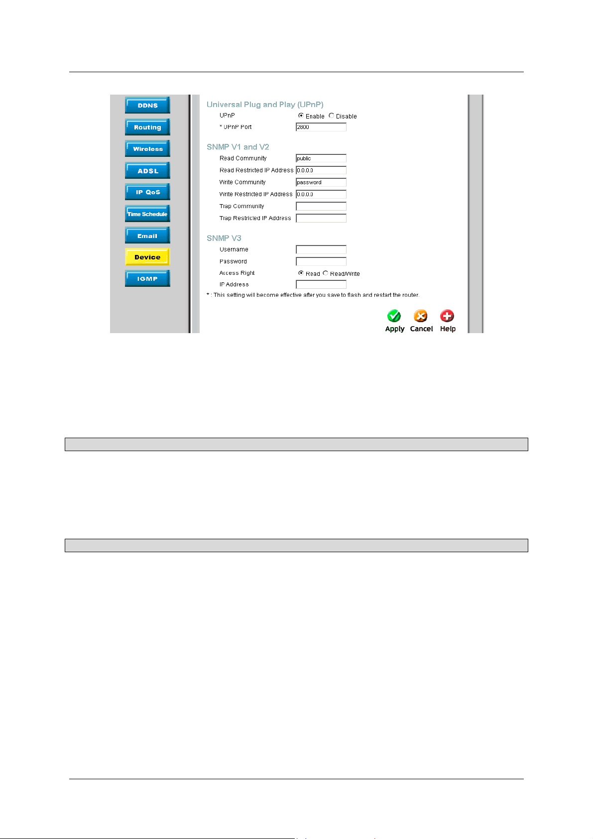
DSL-G804V Wireless ADSL Router User’s Guide
Figure 4-31. Device Management – UPnP, SNMP V1 and V2, and SNMP V3
Universal Plug and Play (UPnP)
UPnP offers peer-to-peer network connectivity for PCs and other network devices, along with control and data
transfer between devices. UPnP offers many advantages for users running NAT routers through UPnP NAT
Traversal, and on supported systems makes tasks such as port forwarding much easier by letting the application
control the required settings, removing the need for the user to control advanced configuration of their device.
Parameter Description
UPnP
UPnP Port
Disable or activate the router’s UPnP functionality.
Its default setting is 2800. It is highly recommended for users to use this port
value. If this value conflicts with other ports already being used you may wish
to change the port. (Important: This setting will become effective after you
Save to flash and restart the router).
SNMP V1 and V2 (Simple Network Management Protocol Version 1 and Version 2)
Parameter Description
Read Community
Specify a name to be identified as the Read Community, and an IP address.
This community string will be checked against the string entered in the
configuration file. Once the string name is matched, user obtains this IP
address will be able to view the data.
Write Community
Specify a name to be identified as the Write Community, and an IP address.
This community string will be checked against the string entered in the
configuration file. Once the string name is matched, users from this IP address
will be able to view and modify the data.
Trap Community
Specify a name to be identified as the Trap Community, and an IP address.
This community string will be checked against the string entered in the
configuration file. Once the string name is matched, users from this IP
address will be sent SNMP Traps.
SNMP V3 (Simple Network Management Protocol Version 3)
Specify a name and password for authentication. And define the access right from identified IP address. Once the
authentication has succeeded, users from this IP address will be able to view and modify the data.
74
Page 83

DSL-G804V Wireless ADSL Router User’s Guide
A
IGMP
IGMP, known as Internet Group Management Protocol, is used to management hosts from multicast group.
Figure 4-32. IGMP
Para meter Description
IGMP Forwarding
IGMP Snooping
Accepting multicast packet. Default is set to Enable.
llowing switched Ethernet to check and make correct forwarding decisions.
Default is set to Disable.
75
Page 84
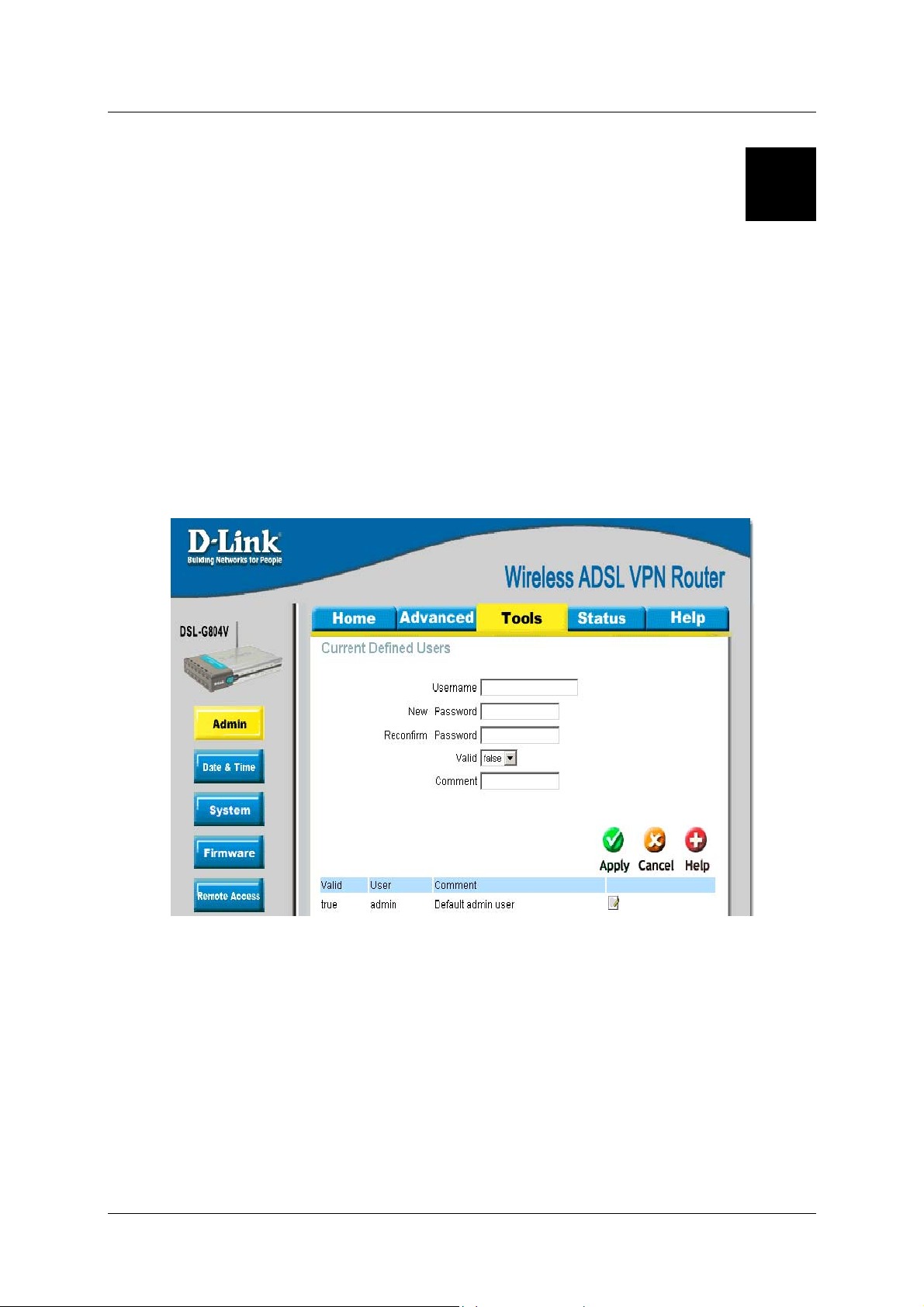
DSL-G804V Wireless ADSL Router User’s Guide
5
Tools
Click the Tools tab to access menus used to configure Admin, Data & Time, System, Firmware, Remote
Access, Reboot, Save Config and Logout.
Admin – Current Defined Users
You can change the user’s password, whether their account is active and Valid, as well as add a comment to
each user account. These options are the same when creating a user account, with the exception that once created
you cannot change the username. You cannot delete the default admin account; however, you can delete any
other created accounts by clicking Delete when editing the user.
Figure 5-1. Admin – Current Defined Users
76
Page 85
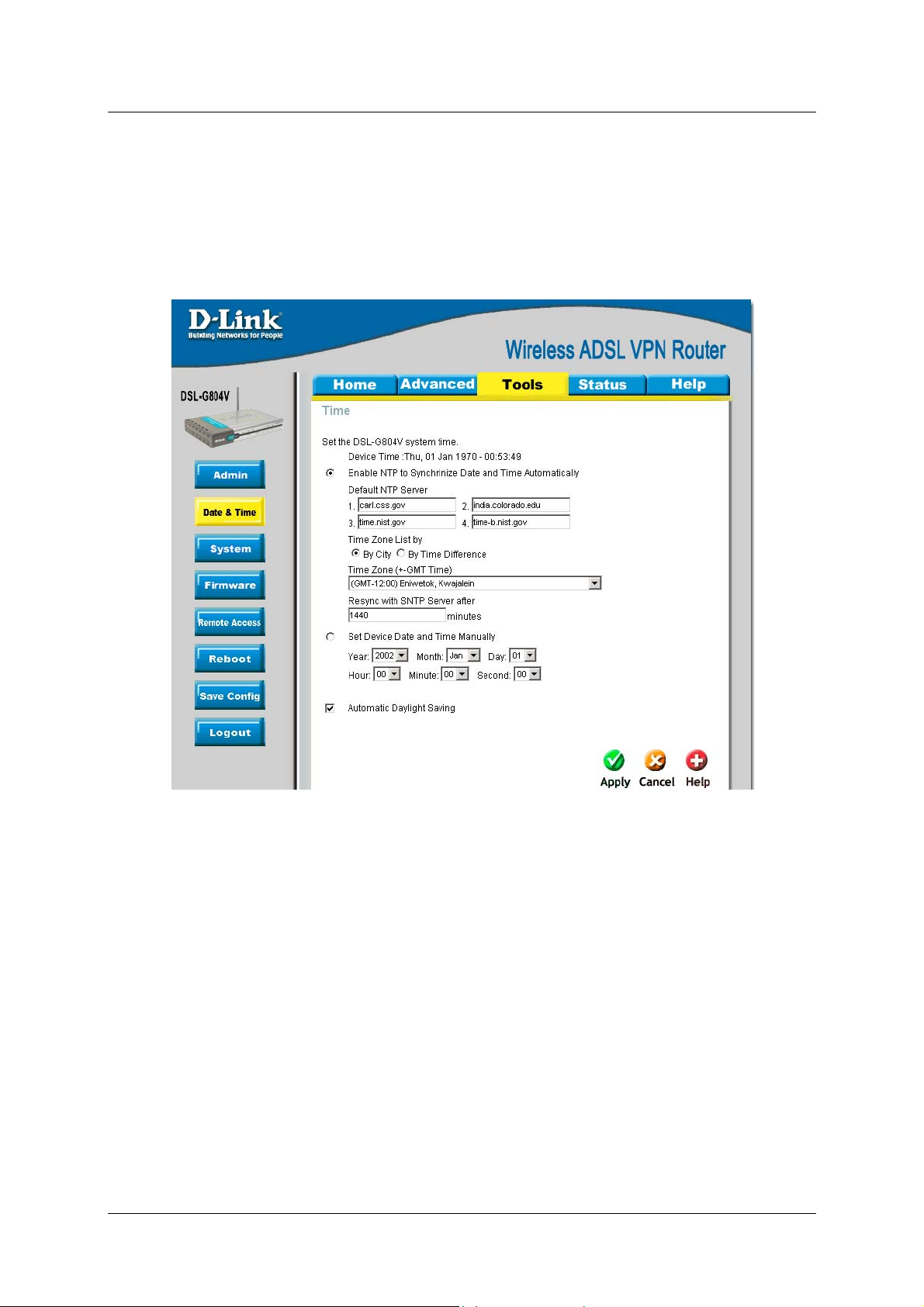
DSL-G804V Wireless ADSL Router User’s Guide
System Date & Time
The router does not have a real time clock on board. You may either select Enable NTP or Set Device Date
and Time manually. Enable NTP uses the Simple Network Time Protocol (SNTP) to get the current time from
an SNTP server outside your network. Also, You can choose Time Zone List by City or By Time Difference.
After a successful connection to the Internet, the router will retrieve the correct local time from the SNTP server
you have specified.
Figure 5-2. Date & Time
Resync Period (in minutes) is the periodic interval the router will wait before it re-synchronizes the router’s
time with that of the specified SNTP server. In order to avoid unnecessarily increasing the load on your specified
SNTP server you should keep the poll interval as high as possible – at the absolute minimum every few hours or
even days.
Daylight Saving is also known as Summer Time Period. Many places in the world adapt it during summer time
to move one hour of daylight from morning to the evening in local standard time. Check Automatic Daylight
Saving box to auto set your local time.
77
Page 86

DSL-G804V Wireless ADSL Router User’s Guide
System Settings
System Setting allows you to save and backup your router’s current settings to a file on your PC, or to restore a
previously saved backup. This is useful if you wish to experiment with different settings, knowing that you have
a backup handy in the case of any mistakes. It is advisable to backup your router’s settings before making any
significant changes to your router’s configuration.
Figure 5-3. System Settings
Press Backup Setting to select where on your local PC to save the settings file. You may also change the name
of the file when saving if you wish to keep multiple backups.
Load Setting From Local Hard Drive: Press Browse to select a file from your PC to restore. You should only
restore settings files that have been generated by the Backup function, and that were created when using the
current version of the router’s firmware. Settings files saved to your PC should not be manually edited in
any way.
78
Page 87
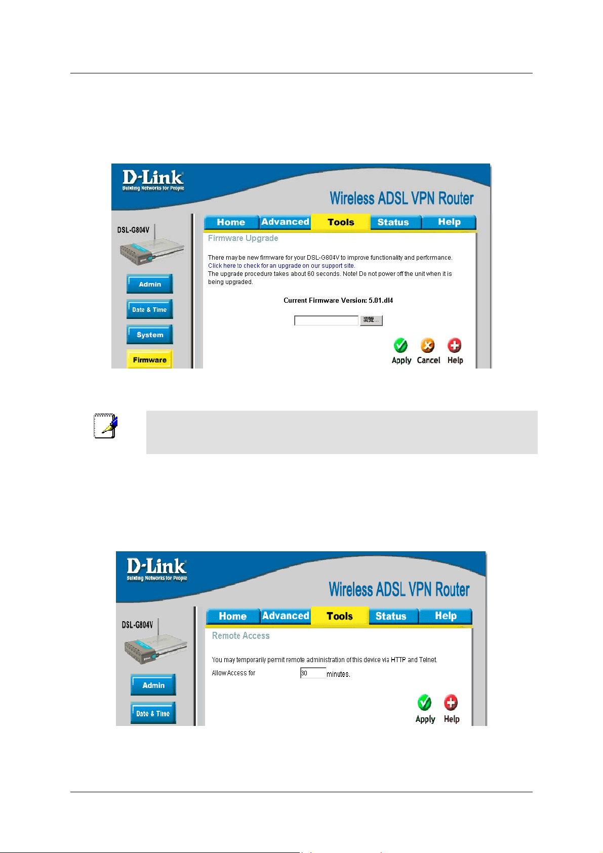
DSL-G804V Wireless ADSL Router User’s Guide
Firmware Upgrade
Your router’s “firmware” is the software that allows it to operate and provides all its functionality. Over time this
software may be improved and modified, and your router allows you to upgrade the software it runs to take
advantage of these changes.
Figure 5-4. Firmware Upgrade
Clicking on Browse will allow you to select the new firmware image file you have downloaded to your PC.
Note
DO NOT power off the router or interrupt the firmware upgrading while it is still in process.
Improper operation could damage the router.
Remote Access
To temporarily permit remote administration of the router (i.e. from outside your LAN), select a time period the
router will permit remote access. You may change other configuration options for the web administration
interface using Device options in the Advanced section of the GUI.
Figure 5-5. Remote Access
79
Page 88
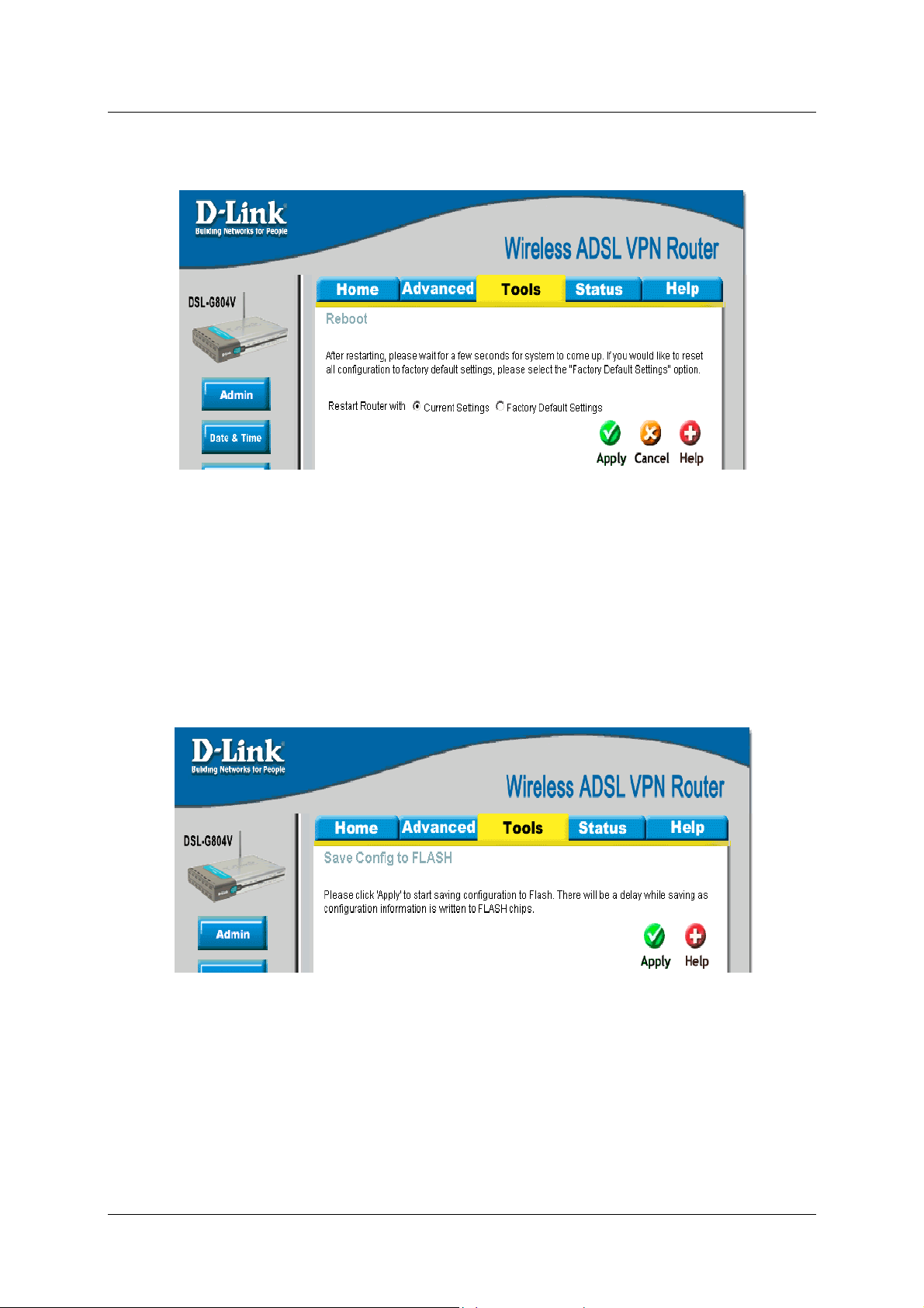
DSL-G804V Wireless ADSL Router User’s Guide
Reboot
Figure 5-6. Reboot
Click Restart with option Current Settings to reboot your router (and restore your last saved configuration).
If you wish to restart the router using the factory default settings (for example, after a firmware upgrade or if you
have saved an incorrect configuration), select Factory Default Settings to reset to factory default settings.
You may also reset your router to factory settings by holding the small Reset pinhole button on the back of your
router in for 10-12 seconds whilst the router is turned on.
Save Config to FLASH
After changing the router’s configuration settings, you must save all of the configuration parameters to FLASH
to avoid them being lost after turning off or resetting your router.
Figure 5-7. Save Config to FLASH
Logout
To exit the router’s web interface, choose Logout. Please ensure that you have saved the configuration settings
before you logout.
80
Page 89

DSL-G804V Wireless ADSL Router User’s Guide
Be aware that the router is restricted to only one PC accessing the configuration web pages at a time. Once a PC
has logged into the web interface, other PCs cannot get access until the current PC has logged out of the web
interface. If the previous PC forgets to logout, the second PC can access the page after a user-defined period, by
default 3 minutes. You can modify this value using the Advanced – Device section of the web interface.
81
Page 90

DSL-G804V Wireless ADSL Router User’s Guide
6
Status
Click the Status tab to access menus used to configure Device Info, ARP, Wireless, Routing, IPSec Status,
PPTP Status, L2TP Status, DHCP, Email, Event Log, NAT Sessions, UPnP Portmap.
Device Information
Device Information detailed displays the current set t i ng of y our rout er such as LAN, WAN, Wireless, Port St at us
and Traffic Statistic.
Figure 6-1. Device Information
82
Page 91

DSL-G804V Wireless ADSL Router User’s Guide
ARP
ARP (Address Resolution Protocol) Table shows the mapping of Internet (IP) addresses to Ethernet (MAC)
addresses. This is useful as a quick way of determining the MAC address of the network interface of your PCs.
Static – no means the ARP table entry is dynamically generated. Yes means the ARP table entry is added by the
users.
Para meter Description
IP Address
MAC Address
Interface
Static
A list of IP addresses of devices on your LAN (Local Area Network)
The MAC (Media Access Control) addresses for each device on your LAN.
The interface name (on the router) that this IP Address connects to.
Static status of the ARP table entry:
“no” for dynamically-generated ARP table entries
“yes” for static ARP table entries added by the user
Figure 6-2. ARP Table
83
Page 92

DSL-G804V Wireless ADSL Router User’s Guide
Wireless (Connect Wireless Client List)
Wireless Client table displays information of the AP client that is connect to the router.
Figure 6-3. Connect Wireless Client List
Para meter Description
IP Address
MAC
It is IP address of wireless client that joins this network.
The MAC address of wireless client.
Routing Table
Two routing tables are displayed, Routing Table and RIP Routing Table.
Figure 6-4. Routing Table
84
Page 93

DSL-G804V Wireless ADSL Router User’s Guide
Para meter Description
Routing Table
Valid
Destination
Netmask
Gateway/Interface
Cost
RIP Routing Table
Destination
Netmask
Gateway
Cost
It indicates a successful routing status.
The IP address of the destination network.
The destination netmask address.
The IP address of the gateway or existing interface that this route will use.
The number of hops counted as the cost of the route.
The IP address of the destination network.
The destination netmask address.
The IP address of the gateway that this route will use.
The number of hops counted as the cost of the route.
IPSec Status
IPSec Status shows details of your configured IPSec VPN connections.
Para meter Description
Name
Active
Connection State
Statistics
Local Subnet
Remote Subnet
Remote Gateway
SA
The name you assigned to the particular VPN entry.
Whether the VPN Connection is currently Active.
Whether the VPN is Conne cted or Disconnected.
Statistics for this VPN Connection.
The local IP Address or Subnet used.
The Subnet of the remote site.
The Remote Gateway IP address.
The Security Association for this VPN entry.
Figure 6-5. IPSec Status
85
Page 94

DSL-G804V Wireless ADSL Router User’s Guide
PPTP Status
PPTP Status shows details of your configured PPTP VPN connections.
Para meter Description
Name
Type
Enable
Active
Tunnel Connected
Call Connected
Encryption
The name you assigned to the particular PPTP connection in your VPN
configuration.
The type of connection (dial-in/dial-out).
Whether the connection is currently enabled.
Whether the connection is currently active.
Whether the VPN Tunnel is currently connected.
If the Call for this VPN entry is currently connected.
The encryption type used for this VPN connection.
Figure 6-6. PPTP Status
L2TP Status
L2TP Status shows details of your configured L2TP VPN connections.
86
Page 95

DSL-G804V Wireless ADSL Router User’s Guide
Para meter Description
Figure 6-7. L2TP Status
Name
Type
Enable
Active
Tunnel Connected
Call Connected
Encryption
The name you assigned to the particular L2TP connection in your VPN
configuration.
The type of connection (dial-in/dial-out).
Whether the connection is currently enabled.
Whether the connection is currently active.
Whether the VPN Tunnel is currently connected.
If the Call for this VPN entry is currently connected.
The encryption type used for this VPN connection.
DHCP Status
DHCP Status table displays DHCP Server assigned IP address information and Subnet Definitions.
87
Page 96
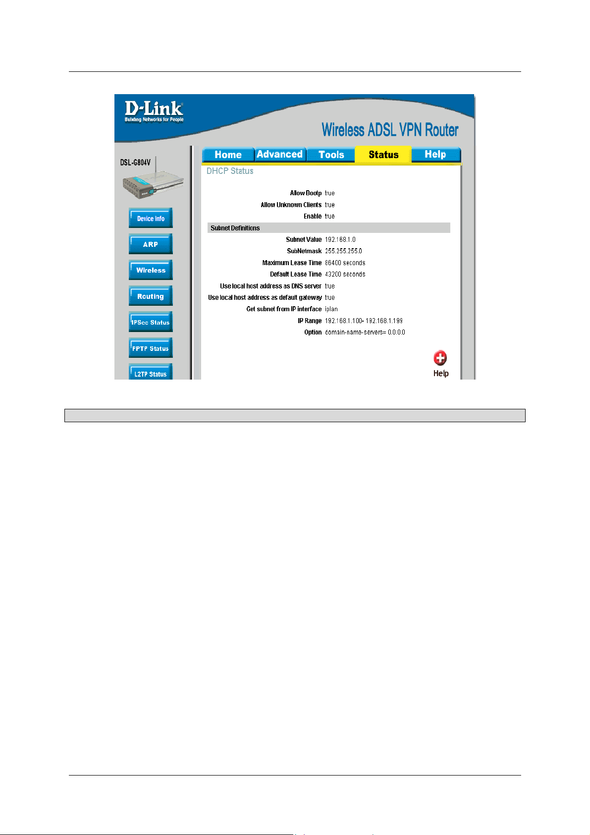
DSL-G804V Wireless ADSL Router User’s Guide
Para meter Description
Allow Bootp
Allow Unknown
It shows in true or false.
It shows in true or false.
Clients
Enable
Subnet
It shows in true or false, if DHCP Server is in enabled.
This is the information of your DHCP Server IP subnet information.
Value/Subnetmask
Maximum Lease
Time
Default Lease Time
The maximum lease time interval you allow. For more information, check
“DHCP” under “Home” section.
The default lease time interval you allow. For more information, check “DHCP”
under “Home” section.
Use local host
It shows in true or false.
address as DNS
Server
Use local host
It shows in true or false
address as default
gateway
Get subnet from IP
Iplan tells the subnet is based on the IP interface.
interface
Figure 6-8. DHCP Status
88
Page 97
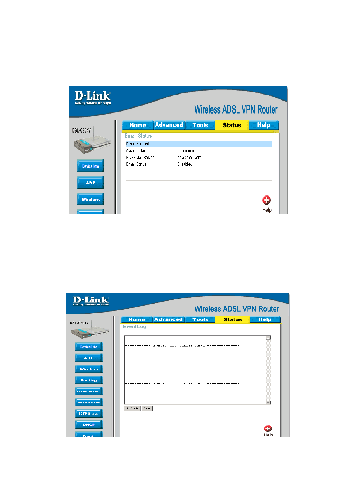
DSL-G804V Wireless ADSL Router User’s Guide
Email Status
Email Status displays details and status of the Email Account you configured in Advanced –Email.
Figure 6-9. Email Status
Event Log
Event Log detailed displays router’s event entries. Major events are logged to this window, such as when the
router’s ADSL connection is disconnected, as well as Firewall events when you have enabled Intrusion or
Blocking Logging in the Advanced – Firewall section of the interface. Please see the Firewall section of this
manual for more details on how to enable Firewall logging.
Figure 6-10. Event Log
89
Page 98

DSL-G804V Wireless ADSL Router User’s Guide
Error Log
Error Log displays any errors encountered by the router (e.g. invalid names given to entries) are logged to this
window.
Figure 6-11. Error Log
NAT Sessions
NAT Sessions list all current NAT session between interface of types external (WAN) and internal (LAN).
Figure 6-12. NAT Sessions
90
Page 99

DSL-G804V Wireless ADSL Router User’s Guide
UPnP Portmap
UPnP Portmap list all port-mapping established using UPnP (Universal Plug and Play).
Figure 6-
13. UPnP Portmap
Help
Help menu links provide more information for configuring various Router functions.
Figure 6-14. Help
91
Page 100

DSL-G804V Wireless ADSL Router User’s Guide
Technical Specifications
GENERAL
A
Standards:
Protocols:
Data Transfer
Rate:
Media Interface:
ITU G.992.1 (G.dmt) Annex A
ITU G.992.2 (G.lite) Annex A
ITU G.994.1 (G.Hs)
ITU-T Rec. I.361
ITU-T Rec. I.610
IEEE 802.3
IEEE 802.3u
IEEE 802.1d
RFC 791 (IP Routing)
RFC 792 (UDP)
RFC 826 (ARP)
RFC 1058 (RIP 1)
RFC 1389 (RIP 2)
RFC 1213 compliant
RFC 1483 (Bridged Ethernet)
TCP/IP
UDP
RIP-1
RIP-2
IGMP
G.dmt full rate: Downstream up to 8 Mbps
Upstream up to 640 Kbps
G.lite: Downstream up to 1.5 Mbps
Upstream up to 512 Kbps
RJ-11 port ADSL telephone line connection
RJ-45 port for 10/100BASET Ethernet connection
RFC 1577 (IP over ATM)
RFC 1661 (PPP)
RFC 1994 (CHAP)
RFC 1334 (PAP)
RFC 2364 (PPP over ATM)
RFC 1631 (NAT)
RFC 1877 (Automatic IP assignment)
RFC 2516 (PPP over Ethernet)
Supports RFC 2131 and RFC 2132 (DHCP)
Compatible with all T1.413 issue 2 (full rate
DMT over analog POTS), and CO DSLAM
equipment
Supports ATM Forum UNI V3.1 PVC
DHCP
BOOTP
ARP
AAL5
92
 Loading...