

Page 1
DSL-G604T Generation II ADSL2+ Wireless Modem Router
Page 1 of 110
www.dlink.com.au
Page 2

DSL-G604T Generation II ADSL2+ Wireless Modem Router
Table of Contents
BEFORE YOU START .................................................................................... 4
Installation Overview ......................................................................................................................... 4
Setup Wizard...................................................................................................................................... 4
Packing List ........................................................................................................................................ 4
Installation Notes .............................................................................................................................. 5
INTRODUCTION .......................................................................................... 8
Router Description and Operation ...................................................................................................... 8
Router Features ................................................................................................................................. 9
802.11g Wireless ............................................................................................................................. 10
Installation Considerations ............................................................................................................... 11
Front Panel Display .......................................................................................................................... 12
Rear Panel Connections ................................................................................................................... 13
Reset ............................................................................................................................................ 14
HARDWARE INSTALLATION ...................................................................... 15
Power on Router .............................................................................................................................. 15
Factory Reset Button ........................................................................................................................ 15
Network Connections ....................................................................................................................... 16
BASIC ROUTER CONFIGURATION ............................................................. 17
Computer IP Settings ...................................................................................................................... 17
Access the Configuration Manager ................................................................................................... 18
Login to Home Page ........................................................................................................................ 18
Configure the Router ........................................................................................................................ 19
Wizard ............................................................................................................................................. 20
Wireless ........................................................................................................................................... 30
WEP.............................................................................................................................................. 31
WPA (Wi-Fi Protected Access) ........................................................................................................... 32
802.1x .......................................................................................................................................... 33
WAN ................................................................................................................................................. 34
PPPoE/PPPoA .................................................................................................................................. 34
Dynamic IP Address ........................................................................................................................ 37
Static IP Address ............................................................................................................................ 40
Bridge Mode ................................................................................................................................... 43
LAN .................................................................................................................................................. 47
DHCP ................................................................................................................................................ 48
DNS .................................................................................................................................................. 51
Dynamic DNS ................................................................................................................................... 52
Save Settings and Reboot ................................................................................................................ 53
Multiple Virtual Connections ............................................................................................................ 54
ADVANCED ROUTER MANAGEMENT .......................................................... 56
UPnP ................................................................................................................................................ 57
Virtual Server ................................................................................................................................... 58
Custom Forwarding Rules................................................................................................................. 60
LAN Clients....................................................................................................................................... 61
SNMP ............................................................................................................................................... 62
Filters ............................................................................................................................................... 63
Bridge Filters ................................................................................................................................... 65
Static Routing .................................................................................................................................. 66
Page 2 of 110 www.dlink.com.au
Page 3

DSL-G604T Generation II ADSL2+ Wireless Modem Router
DMZ .................................................................................................................................................. 67
Parental Control ............................................................................................................................... 68
URL Blocking .................................................................................................................................. 69
Domain Blocking ............................................................................................................................. 69
Firewall ............................................................................................................................................ 70
RIP ................................................................................................................................................... 71
ADSL ................................................................................................................................................ 72
ATM VCC ........................................................................................................................................... 73
QoS .................................................................................................................................................. 74
Wireless Management ...................................................................................................................... 80
Access List ..................................................................................................................................... 80
Associated Stations ......................................................................................................................... 81
Multiple SSID ................................................................................................................................. 82
Wireless Performance ...................................................................................................................... 83
TOOLS ...................................................................................................... 85
Admin .............................................................................................................................................. 86
Change System Password ................................................................................................................ 86
Remote Web Management and Remote Telnet Access .......................................................................... 87
Time ................................................................................................................................................. 88
Remote Log ...................................................................................................................................... 89
System ............................................................................................................................................. 90
Save or Load Configuration File ......................................................................................................... 90
Save Settings and Reboot System ..................................................................................................... 90
Restore Factory Default Settings ....................................................................................................... 90
Force the Wireless LAN to Restart ..................................................................................................... 90
Firmware.......................................................................................................................................... 91
Miscellaneous ................................................................................................................................... 92
Ping Test ....................................................................................................................................... 92
Test .................................................................................................................................................. 93
STATUS ..................................................................................................... 94
Device Info ...................................................................................................................................... 94
DHCP Clients .................................................................................................................................... 95
Log ................................................................................................................................................... 96
Statistics .......................................................................................................................................... 97
ADSL Status ..................................................................................................................................... 98
Help ................................................................................................................................................. 99
TECHNICAL SPECIFICATIONS ................................................................. 100
CONFIGURING IP SETTINGS ON YOUR COMPUTER ................................. 103
LOW PASS FILTERS FOR DSL .................................................................. 108
Page 3 of 110 www.dlink.com.au
Page 4

DSL-G604T Generation II ADSL2+ Wireless Modem Router
About This User Guide
This user’s guide provides instructions on how to install the DSL-G604T ADSL 2+ Router and use it to provide
Internet access for an Ethernet/Wireless network or single computer.
If you are using a computer with a functioning Ethernet port, the quickest and easiest way to set up the DSLG604T is to follow the instructions provided in the Quick Installation Guide (QIG).
Before You Start
Please read and make sure you understand all the prerequisites for proper installation of your new Router. Have
all the necessary information and equipment on hand before beginning the installation.
Installation Overview
The procedure to install the Router can be described in general terms in the following steps:
1. Gather information and equipment needed to install the device. Before you begin the actual installation
make sure you have all the necessary information and equipment.
2. Install the hardware, connect the cables to the device, and connect the power adapter.
3. Check the IP settings on your computer and change them if necessary so the computer can access the webbased software built into the Router.
4. Use the web-based management software to configure the device to suit the requirements of your AD SL
service and requirements of your local network.
Setup Wizard
Many users will be able to configure all the settings necessary to use the DSL-G604T with the Setup Wizard. For
ADSL connections that use PPPoE or PPPoA connections, the simplest way to set up the DSL-G604T is to use
the Setup Wizard to configure the Internet connection. Once you access the web interface used to configure the
device, just launch the Setup Wizard to configure your Internet connection.
Packing List
Open the shipping carton and carefully remove all items. Make sure that you have the items listed here.
• One DSL-G604T GENERATION II ADSL2+ Ethernet Router
• One CD-ROM containing the User’s Guide, Quick Installation Guide and D-Link Click’n Connect Utility
• One twisted-pair telephone cable used for ADSL connection
• One straight-through Ethernet cable
• One DC power adapter suitable for your electrical service
• One Quick Installation Guide
Page 4 of 110 www.dlink.com.au
Page 5

DSL-G604T Generation II ADSL2+ Wireless Modem Router
Installation Notes
In order to establish a connection to the Internet it will be necessary to provide information to the Router that
will be stored in its memory. For some users, only their account information (Username and Password) is
required. For others, various parameters that control and define the Internet connection will be required. You
can print out the two pages below and use the tables to list this information. This way you have a hard copy of
all the information needed to setup the Router. If it is necessary to reconfigure the device, all the necessary
information can be easily accessed. Be sure to keep this information safe and private.
Low Pass Filters
Since ADSL and telephone services share the same copper wiring to carry their respective signals, a filtering
mechanism may be necessary to avoid mutual interference. A low pass filter device can be installed for each
telephone that shares the line with the ADSL line. These filters are easy to install passive devices that connect
to the ADSL device and/or telephone using standard telephone cable. Ask your service provider for more
information about the use of low pass filters with your installation.
Operating Systems
The DSL-G604T uses an HTML-based web interface for setup and management. The web configuration manager
may be accessed using any operating system capable of running web browser software, incl uding Windows 98
SE, Windows ME, Windows 2000, and Windows XP. The D-Link Click’n Connect Utility will only work with a
Windows operating system.
Web Browser
Any common web browser can be used to configure the Router using the web configuration management
software. The program is designed to work best with more recently released browsers such as Microsoft
Internet Explorer® version 6.0, Netscape Navigator® version 6.2.3, or later versions. The web browser must
have JavaScript enabled. JavaScript is enabled by default on many browsers. Make sure JavaScript has not
been disabled by other software (such as virus protection or web user security packages ) that may be running
on your computer.
Ethernet Port (NIC Adapter)
Any computer that uses the Router must be able to connect to it through the Ethernet port on the Router. The
easiest method of installation is via the Ethernet connection and therefore requires that your computer be
equipped with an Ethernet port as well. Most notebook computers are now sold with an Ethernet port already
installed. Likewise, most fully assembled desktop computers come with an Ethernet NIC adapter as standard
equipment. If your computer does not have an Ethernet port, you must install an Ethernet NIC adapter before
you can use the Router. If you must install an adapter, follow the installation instructions that come with the
Ethernet NIC adapter.
Additional Software
For a bridged connection, the information needed to make and maintain the Internet connection is stored on
another computer or gateway device using PPP client or similar third party client software, not in the Router
itself.
If your ADSL service is delivered through a PPPoE, PPPoA or Static IP connection, the information needed to
establish and maintain the Internet connection can be stored in the Router. In this case, it is not necessary to
install software on your computer. It may however be necessary to change some settings in the device,
including account information used to identify and verify the connection.
Page 5 of 110 www.dlink.com.au
Page 6

In
ePasWACon
VPI
VCI
N
o
p
h
i
This
w
v
This
o
The
P
d
tRouDynMuxDefaMos
h
n
vRou
d
t
sCha
t
d
a
DSL-G604
T
r
a
m
u
w
y
e
e
e
P
8
4
e
/
o
V
o
r
a
c
o
t
f
u
s
e
e
o
e
c
e
n
e
o
L
P
d
E
d
d
o
n
b
a
d
D
i
c
e
b
e
e
r
@
t
D
y
T
o
P
r
w
w
o
w
c
t
r
u
V
D
o
Y
o
f
a
C
u
d
e
a
D
o
d
e
u
e
o
p
a
t
o
r
w
d
Generation
II ADSL2+
Wireless M
dem Route
formati
Us
rname
sword
N Setting /
nection Ty
n you w
net
ser
to l
veri
e
to t
use
the
(Co
PP
Bri
Sta
Pat
Ide
pro
the
ad
Set
8
ll need f
is the Usern
ork. It is co
ice provider
is the Pass
g on to your
fy the identit
se settings d
ransport data
rs will use th
following WA
nnection Typ
oE/PPoA (PP
ge Mode (14
ic IP Address
ted IP LLC, 1
amic IP Addr
)
ult = PPPoE
t users will n
Identifier (
tifier (VCI) t
ider’s netwo
ter for multip
VPI and VCI
itional conne
ings window
om your
me used to l
monly in the
ses this to id
ord used, in
ADSL service
of your acco
scribe the m
between the
default setti
N Setting and
settings list
oE LLC, PPP
3 Bridged IP
(Bridged IP
83 Routed I
ss (1483 Bri
PPPoA (PPPo
t be require
PI) is used in
identify the
k and your c
le virtual con
s instructed
tions. This se
of the web m
ADSL se
g on to your
form − user
ntify your ac
onjunction wi
provider’s ne
unt.
thod your A
Internet and
gs. You may
Connection
d in parenthe
A LLC or PPP
LLC or 1483
LC, 1483 Brid
VC-Mux or I
ged IP LLC o
LLC)
to change th
conjunction
ata path bet
mputer. If y
ections, you
y your ADSL
tting can be
nagement in
vice pro
ADSL service
isp.com.au
count.
th the Userna
work. This is
SL service pr
our compute
need to speci
ype configur
sis):
A VC-Mux)
Bridged IP V
ged IP VC-M
oA)
1483 Bridge
is setting. Th
ith the Virtu
een your A
u are setting
ill need to c
service provi
hanged in th
erface. Defa
vider:
provider’s
our ADSL
me above,
used to
vider uses
r. Most
y one of
tions
-Mux)
x, 1483
IP VC-
Virtual
l Channel
SL service
up the
nfigure
er for the
WAN
lt value =
Recor
info here
T
ote
e Setup Wiz
Mo
t users will n
nnel Identifie
the
data path be
r computer. I
you
nections, you
con
ructed by yo
ins
con
nections. Thi
ow of the w
win
rd can be us
t be require
r (VCI) used i
ween your A
you are sett
will need to
r ADSL servic
setting can
b managem
d to configur
to change th
n conjunction
SL service p
ng up the Ro
onfigure the
provider for
e changed in
nt interface.
the Internet
is setting. Th
with the VPI
ovider’s netw
ter for multi
PI and VCI a
the addition
the WAN Set
efault value
connection f
Virtual
to identify
rk and
le virtual
s
l
ings
= 35
r most users.
Pa
ge 6 of 110
ww
.dlink.com
.au
Page 7

DSL-G604T Generation II ADSL2+ Wireless Modem Router
Information you will need about your DSL-G604T ADSL 2+ Router:
Username This is the Username needed access the Router’s management
interface. When you attempt to connect to the device through
a web browser you will be prompted to enter this Username.
The default Username for the Router is “admin.” The user
cannot change this.
Password This is the Password you will be prompted to enter when you
access the Router’s management interface. The default
Password is “admin.” The user may change this.
LAN IP addresses for
the DSL-G604T
LAN Subnet Mask for
the DSL-G604T
This is the IP address you will enter into the Address field of
your web browser to access the Router’s configuration
graphical user interface (GUI) using a web browser. The
default IP address is 10.1.1.1. This may be changed to suit
any IP address scheme the user desires. This address will be
the base IP address used for DHCP service on the LAN when
DHCP is enabled.
This is the subnet mask used by the DSL-G604T, and will be
used throughout your LAN. The default subnet mask is
255.255.255.0. This can be changed later.
Information you will need about your LAN or computer:
Ethernet NIC If your computer has an Ethernet NIC, you can connect the
DSL-G604T to this Ethernet port using an Ethernet cable. You
can also use the Ethernet ports on the DSL-G604T to connect
to other computer or Ethernet devices.
Record info here
Record info here
DHCP Client status Your DSL-G604T ADSL 2+ Router is configured, by default, to
be a DHCP server. This means that it can assign an IP address,
subnet mask, and a default gateway address to computers on
your LAN. The default range of IP addresses the DSL-G604T
will assign are from 10.1.1.2 to 10.1.1.254. Your computer
(or computers) needs to be configured to Obtain an IP
address automatically (that is, they need to be configured
as DHCP clients.)
It is recommended that your collect and record this information here, or in some other secure place, in case
you have to re-configure your ADSL connection in the future.
Once you have the above information, you are ready to setup and configure your DSL-G604T ADSL 2+ Router.
Page 7 of 110 www.dlink.com.au
Page 8

DSL-G604T Generation II ADSL2+ Wireless Modem Router
1
Introduction
This section provides a brief description of the Router, its associated technologies, and a list of Router features.
Router Description and Operation
The DSL-G604T Wireless ADSL2+ Router is designed to provide connectivity for your private Ethernet LAN, and
802.11g/802.11b wireless LAN to the Internet via an ADSL connection.
The Router is easy to install and use. Standard Ethernet ports are used to connect to computer or other
Ethernet devices. The 802.11g wireless interface provides connectivity to 802.11g or 802.11b wireless devices.
802.11g Wireless
The embedded 802.11g wireless access point provides Internet access and connectivity to the Ethernet for
802.11g and 802.11b wireless workstations. IEEE 802.11g is fully compatible with IEEE 802.11b wireless
devices. The 802.11g standard supports data transfer rates of up to 54 M bps. The wirel ess Router supports 64bit and 128-bit WEP encryption, WiFi Protected Access (WPA) and WPA2.
ADSL
Asymmetric Digital Subscriber Line (ADSL) is a broadband network technology that utilises standard twistedpair copper wire telephone lines to enable broadband high-speed digital data transmission and bandwidth
hungry applications for business and residential customers.
ADSL routers and modems provide faster downloads and more reliable connectivity to the user without loss of
quality or disruption of voice/fax telephone capabilities.
ADSL2/2+ provides a dedicated service over a single telephone line operating at speeds of up to 24Mbps
downstream and up to 1Mbps upstream, depending on local telephone line conditions. A secure point-to-point
connection is established between the user and the central office of the service provider.
D-Link ADSL devices incorporate the recommendations of the ADSL Forum regarding framin g, data format, and
upper layer protocols.
Page 8 of 110 www.dlink.com.au
Page 9

DSL-G604T Generation II ADSL2+ Wireless Modem Router
Router Features
The DSL-G604T ADSL 2+ Router utilises the latest ADSL enhancements to provide a reliable Internet portal
suitable for most small to medium sized offices. DSL-G604T advantages include:
PPP (Point-to-Point Protocol) Security – The DSL-G604T ADSL 2+ Router supports PAP (Password
Authentication Protocol) and CHAP (Challenge Handshake Authentication Protocol) for PPP connections.
DHCP Support – Dynamic Host Configuration Protocol automatically and dynamically assigns all LAN IP
settings to each host on your network. This eliminates the need to reconfigure every host whenever changes in
network topology occur.
Network Address Translation (NAT) – For small office environments, the DSL-G604T allows multiple users
on the LAN to access the Internet concurrently through a single Internet account. This provides Internet access
to everyone in the office for the price of a single user.
NAT improves network security in effect by hiding the private network behind one global and visible IP address.
NAT address mapping can also be used to link two IP domains via a LAN-to-LAN connection.
TCP/IP (Transfer Control Protocol/Internet Protocol) – The DSL-G604T supports TCP/IP protocol, the
language used for the Internet. It is compatible with access servers manufactured by major vendors.
RIP-1/RIP-2 – The DSL-G604T supports both RIP-1 and RIP-2 exchanges with other routers. Using both
versions lets the Router to communicate with all RIP enabled devices.
Static Routing – This allows you to select a data path to a particular network destination that will remain in
the routing table and never “age out”. If you wish to define a specific route that will always be used for data
traffic from your LAN to a specific destination within your LAN (for example to another router or a server) or
outside your network (to an ISP defined default gateway for instance).
Default Routing – This allows you to choose a default path for incoming data packets for which the
destination address is unknown. This is particularly useful when/if the Router functions as the sole connection
to the Internet.
ATM (Asynchronous Transfer Mode) – The DSL-G604T supports Bridged Ethernet over ATM (RFC1483), IP
over ATM (RFC1577) and PPP over ATM (RFC 2364).
Precise ATM Traffic Shaping – Traffic shaping is a method of controlling the flow rate of ATM data cells. This
function helps to establish the Quality of Service for ATM data transfer.
G.hs (Auto-handshake) – This allows the Router to automatically choose either the G.lite or G.dmt ADSL
connection standards.
High Performance – Very high rates of data transfer are possible with the Router. Up to 8 Mbps downstream
bit rate using the G.dmt standard.
Full Network Management – The DSL-G604T incorporates SNMP (Simple Network Management Protocol)
support for web-based management and text-based network management via an RS-232 or Telnet connection.
Telnet Connection – The Telnet enables a network manager to access the Router’s management software
remotely.
Easy Installation – The DSL-G604T uses a web-based graphical user interface program for convenient
management access and easy set up. Any common web browser software can be used to manage the Router.
Page 9 of 110 www.dlink.com.au
Page 10

DSL-G604T Generation II ADSL2+ Wireless Modem Router
802.11g Wireless
In order to get the best performance from the wireless component of the Router, you should have some basic
understanding of how wireless networks operate. There are more factors to consider when setting up or
designing a wireless network than designing a wired network. If you are setting up a wireless network,
especially if you are using multiple access points and/or covering a large area, good planning from the outset
can ensure the best possible reliability, performance, coverage and effective security.
Radio Transmission
Wireless local network (also called WI-FI) devices such as notebook computers and wirel ess access points use
electromagnetic waves within a broad, unlicensed range of the radio spectrum (between 2.4GHz and 2. 5GHz) to
transmit and receive radio signals. A wireless access point (AP) becomes a base station for the wireless node s
(a notebook computer for example) in its broadcast range. Often a wireless access point such as the AP
embedded in the DSL-G604T will also provide a connection to a wired network - usually Ethernet - and
ultimately an Internet connection. The IEEE 802.11 standard precisely defines the encoding techniques used for
data transmission. The DSL-G604T can be used by IEEE 802.11g and 802.11b devices. These two standards are
compatible but use different encoding methods for data transmission.
802.11g uses a method called Orthogonal Frequency Division Multiplexing (OFDM) for transmitting data at
higher data rates. OFDM is a more efficient encoding method than Direct Sequence Spread Spectrum (DSSS)
transmission, the method used by 802.11b devices. However, in order to support different data transmission
rates while maintaining compatibility with 802.11b - 802.11g uses a combination of OFDM and DSSS when
802.11b devices are present.
Range
An access point will send and receive signals within a limited range. The actual effective range of the AP can
vary depending on operating conditions. Radio signals are emitted in all directions giving the access point a
spherical range. The physical environment in which the AP is operating can impact on its effectiveness and
range. If you experience low signal strength or slow throughput, consider positioning the Router in a different
location. See Installation Considerations below concerning the wireless environment and location of the AP
(DSL-G604T).
SSID
Wireless networks use an SSID (Service Set Identifier) as means of identifying a group of wireless devices,
similar to a domain or subnet. This allows wireless devices to roam from one AP to another and remain
connected. Wireless devices that wish to communicate with each other must use the same SSID. Several
access points can be set up using the same SSID so that wireless stations can move from one location to
another without losing connection to the wireless network.
The embedded wireless access point of the Router operates in Infrastructure mode. It controls network access
on the wireless interface in its broadcast area. It will allow access to the wireless network to devi ces using the
correct SSID after a negotiation process takes place. By default, the DSL-G604T broadcasts its SSID so that
any wireless station in range can learn the SSID and ask permission to associate with it. Many wireless
adapters are able to survey or scan the wireless environment for access points. An access point in
Infrastructure mode allows wireless devices to survey that network and select an access point with which to
associate. You may disable SSID broadcasting in the web manager’s wireless menu.
Channel
The AP can operate on different channels (frequency bands). This is useful when multiple APs are used in order
to avoid unwanted overlap or interference between control zones of separate APs. Wireless nodes must use the
same SSID and the same channel as the AP with which it will associate. However, using the same channel on
two different APs can contribute wireless congestion under certain circumstances. If you are using multiple APs
on your network and are experiencing low throughput or significant transmission delay, carefully consider how
channels are assigned to the different APs.
Wireless Security
Various security options are available on the Router including open or WEP, WPA and WPA2.
Page 10 of 110 www.dlink.com.au
Page 11

DSL-G604T Generation II ADSL2+ Wireless Modem Router
Installation Considerations
Many physical environmental factors can impact wireless networks. Radio waves are used to carry the encoded
data between devices. These radio transmissions can become degraded due to signal attenuation, multi-path
distortion and interference or noise. Attenuation simply means that the strength of the signal weakens with the
distance it travels, even if the transmission path is unobstructed. Multi-path distortion occurs when radio
signals bounce off objects like walls, ceilings, metal appliances, etc. This may cause a signal to be duplicated,
with each separate yet identical signal arriving at a receiver at different times. Interference and noise from
electrical devices such as microwave ovens, fluorescent lights, automobile engines and other radio emitting
devices can cause signal degradation. With all of this in mind, choose a location for all your access points
including the DSL-G604T.
The access point can be placed on a shelf or desktop, ideally you should be able to see the LED indicators on
the front if you need to view them for troubleshooting.
Wireless networking lets you access your network from nearly anywhere you want. However, the number of
walls, ceilings, or other objects that the wireless signals must pass through can limit signal range. Typical
ranges vary depending on the types of materials and background RF noise in your home or busi ness. To range
and signal strength, use these basic guidelines:
Keep the number of walls and ceilings between the DSL-G604T and other network devices to a minimum - each
wall or ceiling can reduce your D-Link wireless product’s range from 3-90 feet (1-30 metres.) Position your
devices so that the number of walls or ceilings is minimised.
Be aware of the direct line between network devices. A wall that is 1.5 feet thick (0.5 metres), at a 45-degree
angle appears to be almost 3 feet (1 metre) thick. At a 2-degree angle it looks over 42 feet (14 metres) thick!
Please position devices so that the signal will travel straight through a wall or ceiling (instead of at an angle) for
better reception.
Materials can impede the wireless signal - a solid metal door or aluminum studs may have a negative effect on
range. Try to position wireless devices and computers with wireless adapters so that the signal passes through
drywall or open doorways and not dense, especially metallic, materials. Also, note that metal filing cabinets and
appliances can reflect radio signals. When these metal objects are moved around, your wi reless network may
be affected.
Keep your product away (at least 3-6 feet or 1-2 metres) from electrical devices or appliances that generate
extreme RF noise such as microwave ovens, CRT monitors, motors, etc.
Page 11 of 110 www.dlink.com.au
Page 12
DSL-G604T Generation II ADSL2+ Wireless Modem Router
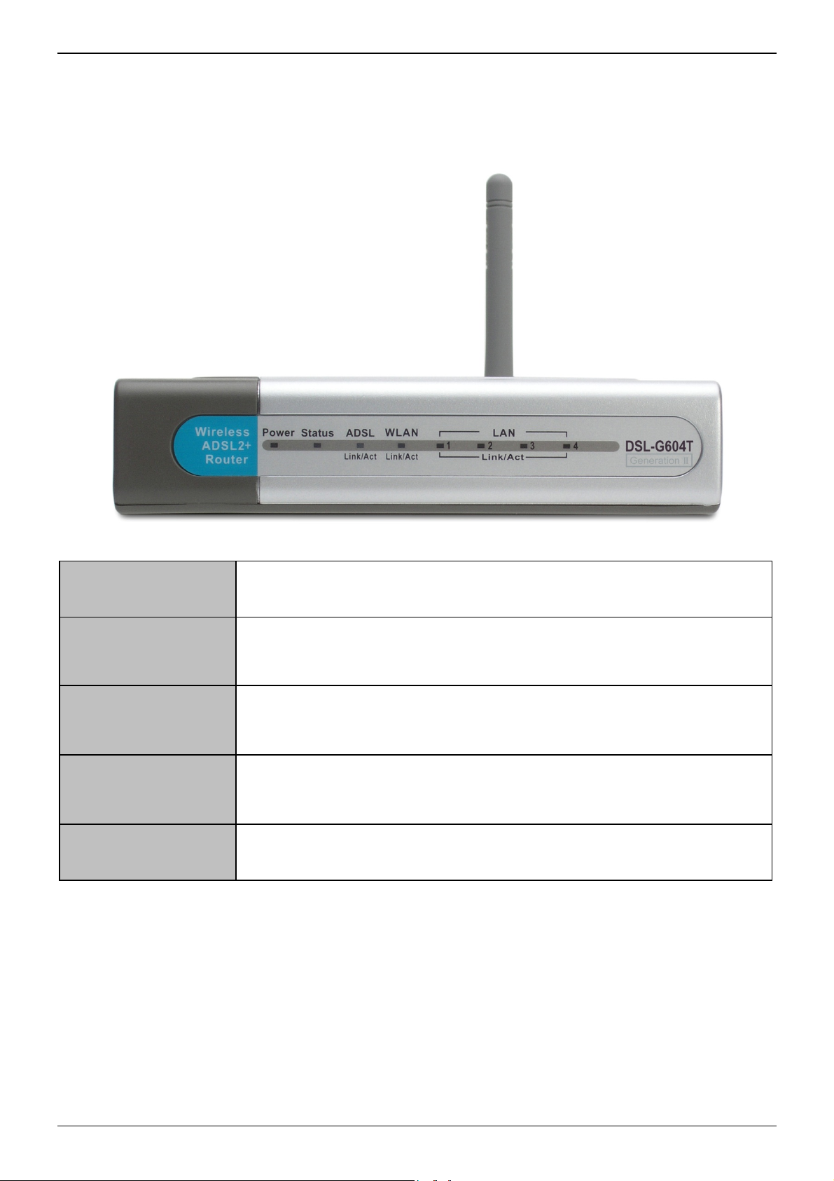
Front Panel Display
Place the Router in a location that permits an easy view of the LED indicators on the front panel.
The LED indicators on the front panel include Power, Status, ADS L, WLAN and Ethernet. The ADSL, WLAN
and Ethernet indicators monitor link status and activity (Link/Act).
Power Steady green light indicates the unit is powered on. When the device is powered off this
remains dark.
Status Lights steady green during power on self-test (POST). Once the connection status has been
settled, the light will blink green. If the indicator lights steady green after the POST, the
system has failed and the device should be rebooted.
ADSL (Link/Act) Steady green light indicates a valid ADSL connection. This will light after the ADSL
negotiation process has been settled. A blinking green light indicates activity on the WAN
(ADSL) interface.
WLAN (Link/Act) Steady green light indicates a wireless connection. A blinking green light indicates activity on
the WLAN interface.
LAN 1-4 (Link/Act) A solid green light indicates a valid link on startup. This light will blink when there is activity
currently on any Ethernet port.
Page 12 of 110 www.dlink.com.au
Page 13
DSL-G604T Generation II ADSL2+ Wireless Modem Router
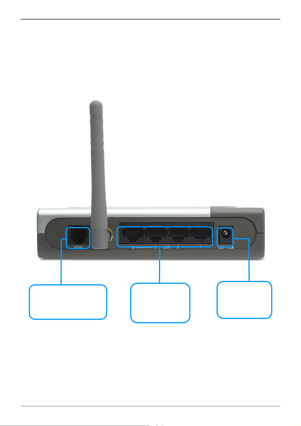
Rear Panel Connections
All cable connections to the Router are made at the rear panel. Connect the power adapter here to power on
the Router. Use the Reset button to restore the settings to the factory default values in the next chapter for
instructions on using the reset button).
Connect network cables:
1. Insert the ADSL (telephone) cable included with the Router into the ADSL port and then connect the cable
to your telephone line.
2. Insert one end of the Ethernet cable into the Ethernet (LAN) port on the back panel of the Router and th e
other end of the cable to an Ethernet Adapter or available Ethernet port on your computer.
Use the ADSL cable to connect to
the your telephone line (RJ-11
ADSL Port
port)
Ethernet Port
Use the Ethernet port to
connect the Router to
your Ethernet LAN or
computer
Power Insert
Use the adapter
shipped with the
Router to connect to
power source
Page 13 of 110 www.dlink.com.au
Page 14
DSL-G604T Generation II ADSL2+ Wireless Modem Router
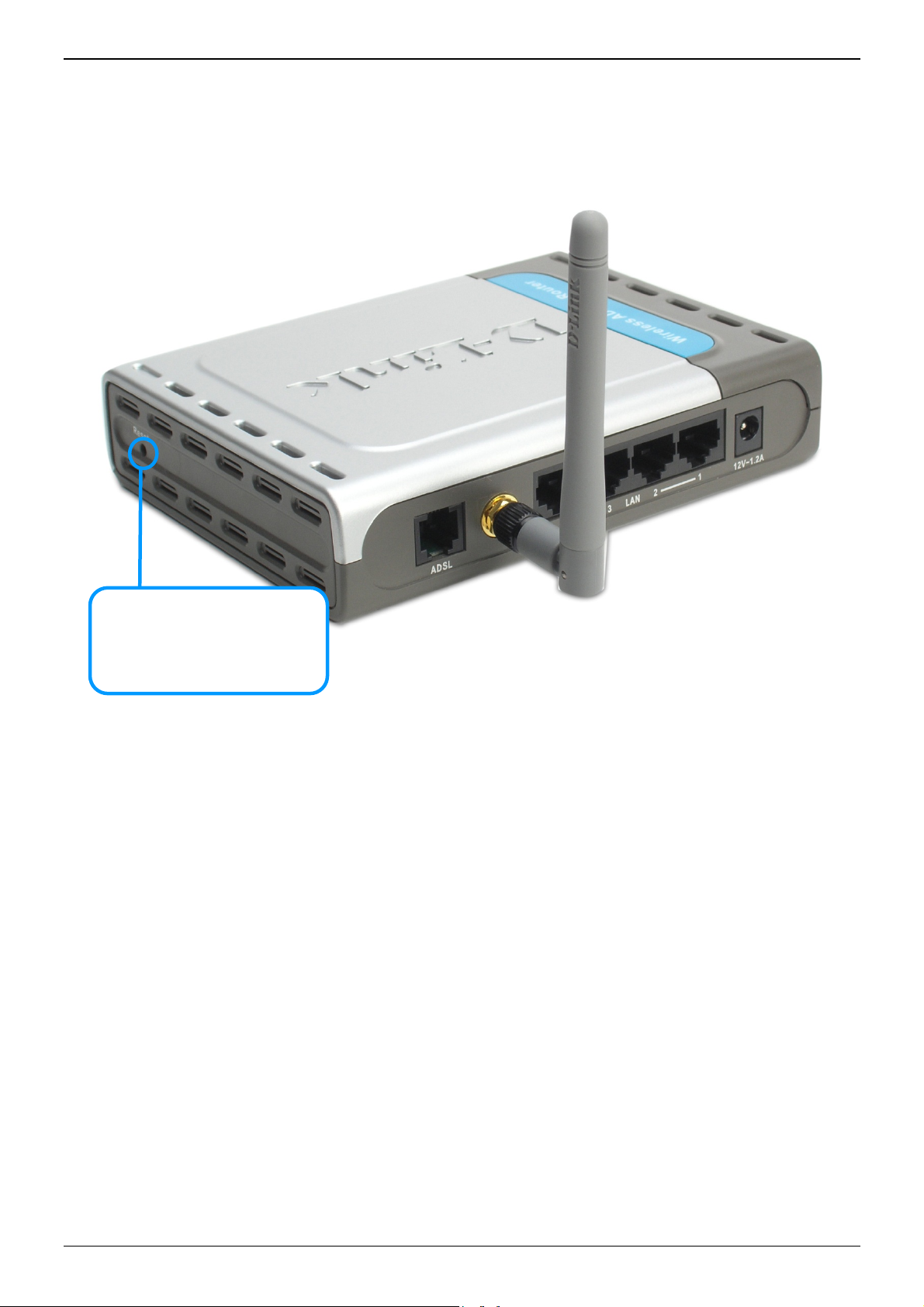
Reset
To Reset the Router to factory default settings including the default IP address 10.1.1.1, depress the reset
button on the right side panel with a ballpoint pen, paper clip or similar object for a few seconds. The device
will restart with default settings.
Reset
To manually reset, depress button
with the power on for at least
seven seconds
Page 14 of 110 www.dlink.com.au
Page 15

DSL-G604T Generation II ADSL2+ Wireless Modem Router
2
Hardware Installation
The DSL-G604T maintains two separate physical interfaces, an ADSL and an Ethernet interface. Place the
Router in a location where it can be connected to the various devices as well as to a power source. The Router
should not be located where it will be exposed to moisture or excessive heat. Make sure the cables and power
cord are placed safely out of the way so they do not create a tripping hazard. As with any electrical appliance,
observe common sense safety procedures.
The Router can be placed on a shelf or desktop, ideally you should be able to see the LED indicators on the
front if you need to view them for troubleshooting.
Power on Router
CAUTION: The Router must be used with the power adapter included with the device.
To power on the Router:
1. Insert the DC Power Adapter cord into the power receptacle located on the rear panel of the Router and
plug the adapter into a suitable nearby power source.
2. You should see the Power LED indicator light up and remain lit. The Status LED should light solid green and
begin to blink after a few seconds.
3. If the Ethernet port is connected to a working device, check the Ethernet Link/Act LED indicators to make
sure the connection is valid. The Router will attempt to establish the ADSL connection, if the ADSL line is
connected and the Router is properly configured this should light up after several seconds. If this is the first
time installing the device, some settings may need to be changed before the Router can establish a
connection.
Factory Reset Button
The Router may be reset to the original factory default settings by depressing the reset button on the right side
panel (see illustration on page 14) for a few seconds while the device is powered on. Use a ballpoint or
paperclip to gently push down the reset button. Remember that this will wipe out any settings stored in flash
memory including user account information and LAN IP settings. The device settings will be restored to the
factory default IP address 10.1.1.1 and the subnet mask is 255.255.255.0, the default management Username
is “admin” and the default Password is “admin.”
Page 15 of 110 www.dlink.com.au
Page 16

DSL-G604T Generation II ADSL2+ Wireless Modem Router
Network Connections
Network connections are provided through the ADSL port and Ethernet port on the back of the Router. See the
Rear Panel diagram above and the illustrations below for examples.
Connect ADSL Line
Use the ADSL cable included with the Router to connect it to a telephone wall socket or receptacle. Plug one
end of the cable into the ADSL port (RJ-11 receptacle) on the rear panel of the Router and insert the other end
into the RJ-11 wall socket. If you are using a low pass filter device, follow the instructions included with the
device or given to you by your service provider. The ADSL connection represents the WAN interface, the
connection to the Internet. It is the physical link to the service provider’s network backbone and ultimately to
the Internet.
Connect Router to Ethernet
The Router may be connected to a single computer or Ethernet device through the 10/100 BASE-TX Ethernet
port on the rear panel. Any connection to an Ethernet concentrating device such as a switch or hub must
operate at a speed of 10/100 Mbps only. When connecting the Router to any Ethernet device that is capable of
operating at speeds between 0~100Mbps, be sure that the device has auto-negotiation (NWay) enabled for the
connecting port.
Use Category 5 or better twisted-pair Ethernet cable with RJ-45 connectors. The RJ-45 port on the Router is
auto MDI-X/MDI-II meaning that is will link correctly with either MDI-II through or MDI-X crossed ports.
The rules governing Ethernet cable lengths apply to the LAN to Router connection. Be sure that the cable
connecting the LAN to the Router does not exceed 100 metres.
Page 16 of 110 www.dlink.com.au
Page 17
B
mto conRo
o
o
TC
oIns
s
N
0
R
n
a
e
t
Y
e
s
i
p
s
e
e
z
e
L
n
I
o
l
o
s
e
y
e
t
t
t
r
o
m
t
t
m
e
h
e
m
t
m
u
S
e
n
o
o
g
o
d
u
u
DSL-G604
T
f
t
o
a
g
o
T
m
n
s
e
p
)
d
e
y
o
o
p
o
v
W
p
n
b
a
m
t
t
s
n
e
f
w
t
o
o
e
o
n
m
t
a
o
e
y
W
p
n
n
g
s
s
e
u
e
h
n
c
e
e
r
t
a
o
n
P
n
o
f
p
o
u
f
H
a
R
e
,
m
c
t
o
s
t
b
u
i
a
p
t
p
e
r
y
D
r
N
p
F
k
o
e
l
a
b
P
i
s
N
h
o
e
m
o
y
a
s
w
u
t
o
a
n
c
y
n
e
o
i
n
p
u
f
t
a
r
a
n
n
n
n
w
f
w
t
n
a
n
e
v
n
v
W
P
o
B
Generation
II ADSL2+
Wireless M
dem Route
3
asic
Th
e first time
co
puter con
make chan
figure adv
uter Manag
C
nfigura
1.
Connect
necessary
browser.
Router is
managem
the same
to configu
computer
configurat
another o
obtain IP
Consult th
2.
Configur
Setup Wi
managem
provider’s
configured
to you by
your ADS
connectio
oute
you setup
ected direc
ges to Rou
nced featu
ment secti
tion Su
o the Rou
to access t
our compu
in the sa
nt softwar
ubnet as t
re it to us
to use a b
on for a co
erating sys
ettings fro
user man
the Inter
ard. The
nt softwar
network a
by default.
your ISP. Y
service. Y
.
r Con
he Router i
ly to the R
er configur
es such as
n.
mary
er To confi
he Router’s
er must be
e “neighb
. Therefore
e Router.
the DHCP
rowser to
puter run
em, make
the Rout
al for the o
net (WAN
etup Wizar
. There ar
d ultimatel
However y
u may als
ur service
igur
is recom
uter. Once
tion includ
port redirec
ure variou
manageme
able to “se
rhood” or
you must
he easiest
server in
anage the
ing a Wind
ure your c
r. Some op
erating sys
Connecti
can be lau
different
to the In
u will prob
need to kn
rovider sh
tion
ended that
he WAN co
ing IP setti
ion, filterin
settings u
t HTML-ba
” the Rout
subnet as
irst make s
ay to mak
he Router.
Router. T
ws operati
mputer is
rating syst
tem (OS) if
n Most us
ched once
ethods us
ernet. You
bly at leas
ow the enc
uld provide
you config
nection is
gs and D
and firew
ed by the
ed interfac
r before it
the Router
re your co
sure your
The DHCP
e next sec
g system t
onfigured a
ems will au
you are uns
rs will be a
you have s
d to establ
Router m
have to ty
psulation a
all the info
re the WA
unctioning
CP setup.
ll, please s
outer for In
. This is d
can manag
you shou
puter has
omputer h
server will
ion descri
be a DHC
a DHCP cl
omatically
ure.
le to comp
ccessfully c
sh the WA
y already
e in a user
nd connecti
rmation ne
connection
roperly, yo
or informa
ip ahead t
ternet and
ne using a
it using a
d be able
IP settings
s the corre
automatical
es how to
client. If
ent so it ca
elect the b
lete this pr
onnected w
connectio
ave most
name and
n type req
ded to con
using a si
may conti
ion on ho
the Advan
ccess it is
ordinary
browser. If
to access
that place i
t IP setting
ly enable y
change the
ou are run
automatic
st IP setti
cess using
th the Rout
to the ser
f the setti
assword gi
ired to use
igure the
gle
ue
to
ced
irst
eb
the
the
in
s is
our
IP
ing
lly
gs.
the
r’s
ice
gs
en
for
AN
C
mputer
In
order to c
P/IP protoc
pr
tocol insta
tructions f
pa
ge 103.
Fo
r computer
tem to rec
sy
ote
P Settin
nfigure you
ol installed.
led. If you
r configurin
running n
ive an IP a
If
ou are not s
S
ttings on Yo
gs
r system t
If you ha
are using
your com
n-Windows
dress from
re how to co
r Computer
receive IP
e an Ether
indows XP
uter to rec
operating s
the Router,
figure your
eginning on
settings fr
net port o
the TCP/I
ive IP setti
stems, foll
that is, con
indows com
age 107.
m the Rou
your com
is enabled
gs from th
w the inst
igure the s
uter to be a
er your co
uter, it pr
by default
Router are
uctions for
stem to be
HCP client,
puter mus
bably alre
for standa
provided in
our OS th
DHCP clie
ee Configuri
first have
dy has TC
d installati
Appendix
t configure
t.
g IP
the
/IP
ns.
on
the
Pa
ge 17 of 11
ww
.dlink.com
.au
Page 18
A
con
o
the
d
nRo
0
th
a
r
u
x
W
rNO
A
e
o
e
y
e
p
m
h
n
e
hac
f
w
n
o
n
o
c
e
a
t
c
w
i
a
T
i
r
e
p
m
x
t
c
n
w
e
c
e
s
d
a
m
m
u
g
d
n
g
t
o
b
e
o
o
C
e
n
u
a
1
s
c
e
a
e
t
e
f
t
s
e
o
r
b
P
a
b
P
o
c
f
n
r
d
h
n
m
1
u
s
n
e
t
r
e
t
g
P
d
m
e
n
s
s
w
d
n
s
e
o
A
e
s
s
a
a
ccess
In
ho
w to config
Note
L
order to m
figure you
Be sure th
Internet E
1. In
2. In t
3. In t
4. In t
5. Ve
lternativ
gin to H
e Con
ke sure yo
system be
re different
at the web bro
plorer, you ca
indows, click
he Control Pa
he Network an
he Internet Pr
ify that the “Us
T checked. If it
ly, you can ac
me Pag
DSL-G604
igurat
ur compute
a DHCP cli
Windows o
ser on your co
check if a pro
n the Start bu
el window, cli
d Internet Co
perties windo
e a proxy serv
is checked, cli
ess this Intern
Generation
on Ma
’s IP settin
nt – that is
erating sys
puter is not c
y server is ena
ton and choos
k on the Netw
nections wind
, click on the
r for your LAN
k in the check
t Options me
II ADSL2+
ager
s allow it t
, it will get
ems to “Ob
nfigured to us
led using the
Control Pane
rk and Interne
w, click the In
onnections ta
(These setting
d box to desel
u using the To
Wireless M
o communi
P settings
ain IP setti
a proxy serve
ollowing proce
l.
t Options icon.
ernet Options
b and click on t
will not apply
ct the option a
ls pull-down
dem Route
ate with th
rom the Ro
gs automa
in the Internet
ure:
icon.
e LAN Settin
to dial-up or V
d click OK.
enu in Internet
Router, it
uter. Appen
ically”.
settings. In Wi
s button
N connection
Explorer.
is advisabl
ix B descri
dows
).” option is
to
bes
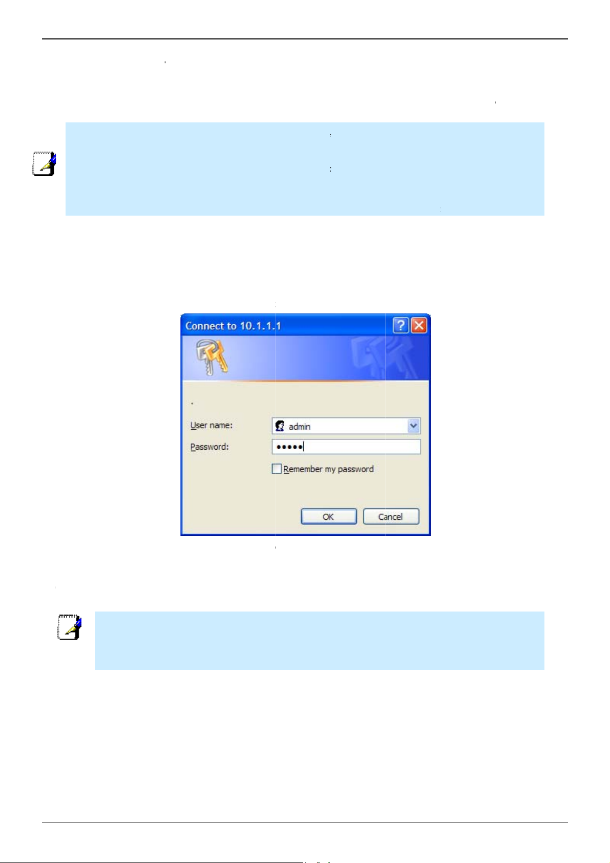
To
use the w
Router. T
Th
e URL in th
ialog box
A
Pa
ssword “ad
b-based m
pe in http:
address ba
rompts for
in” then cli
nagement
// followe
r should re
he User Na
k the OK b
oftware, la
by the def
d: http://
e and Pas
utton to ac
Enter Us
nch a suita
ult IP add
0.1.1.1.
word. Type
ess the we
rname and
ble web bro
ess, 10.1.
in the defa
-based man
assword
wser and di
.1 in the a
lt User Na
ager.
rect it to th
dress bar
e “admin”
IP addres
f the brow
and the def
of
er.
ult
u should c
Yo
nection ca
co
uter to acc
ange the
be establ
ss the web-
eb-based
shed. The
based man
anager acc
ser name
er.
ess user n
nd passwo
me and pa
rd allows a
sword onc
y PC withi
you have
the same
verified th
subnet as
t a
the
T
Note
e user name
count user n
and passwor
me and pass
used to acc
word needed
ss the web-
for PPPoE/P
ased manag
PoA connec
r is NOT the
ions to acces
ame as the
the Internet.
DSL
Pa
ge 18 of 11
ww
.dlink.com
.au
Page 19
DSL-G604T Generation II ADSL2+ Wireless Modem Router
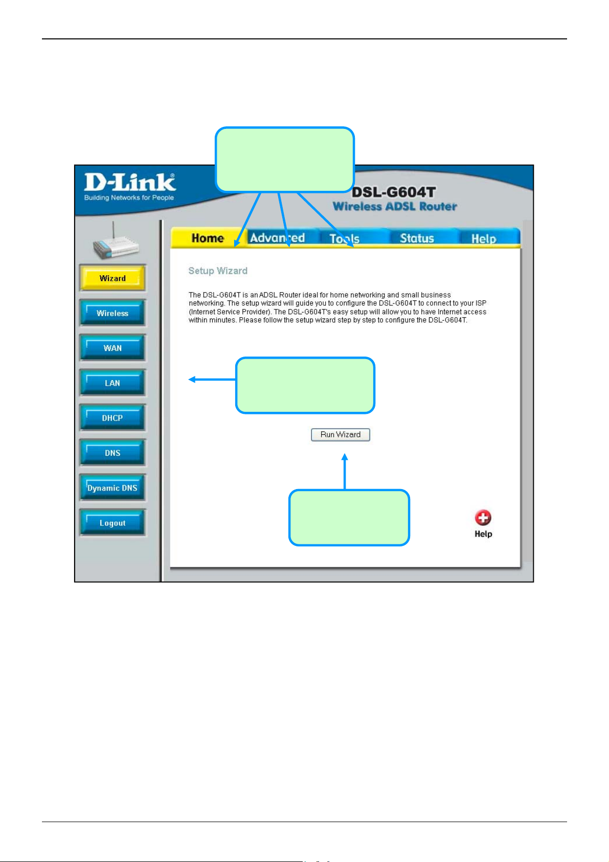
Configure the Router
When you successfully connect to the web manager, the Home directory tab will display the Setup Wizard
window. You can launch the Setup Wizard from this page or use the buttons located in the left panel of the web
page to view other windows used for basic configuration.
Click on a directory tab to
view the options available in
that directory
Click on a button to use or
view the window
Click the Run Wizard
button to launch the
Setup Wizard
Web Manager – First Time Log On
All configuration and management of the Router is done using the web-based management interface pictured in
the above example. The configuration windows are accessed by clicking on the directory tabs: Home,
Advanced, Tools, Status, and Help. Each tab has associated window buttons in the left hand panel of the
web interface. Basic setup of the Router can be completed in the windows accessed from the Home directory
including: (Setup) Wizard, Wireless (to configure the Wirel ess LAN), WAN (Internet), LAN (to configure the
IP address of the Router) DHCP, DNS and Dynamic DNS.
Page 19 of 110 www.dlink.com.au
Page 20
DSL-G604T Generation II ADSL2+ Wireless Modem Router
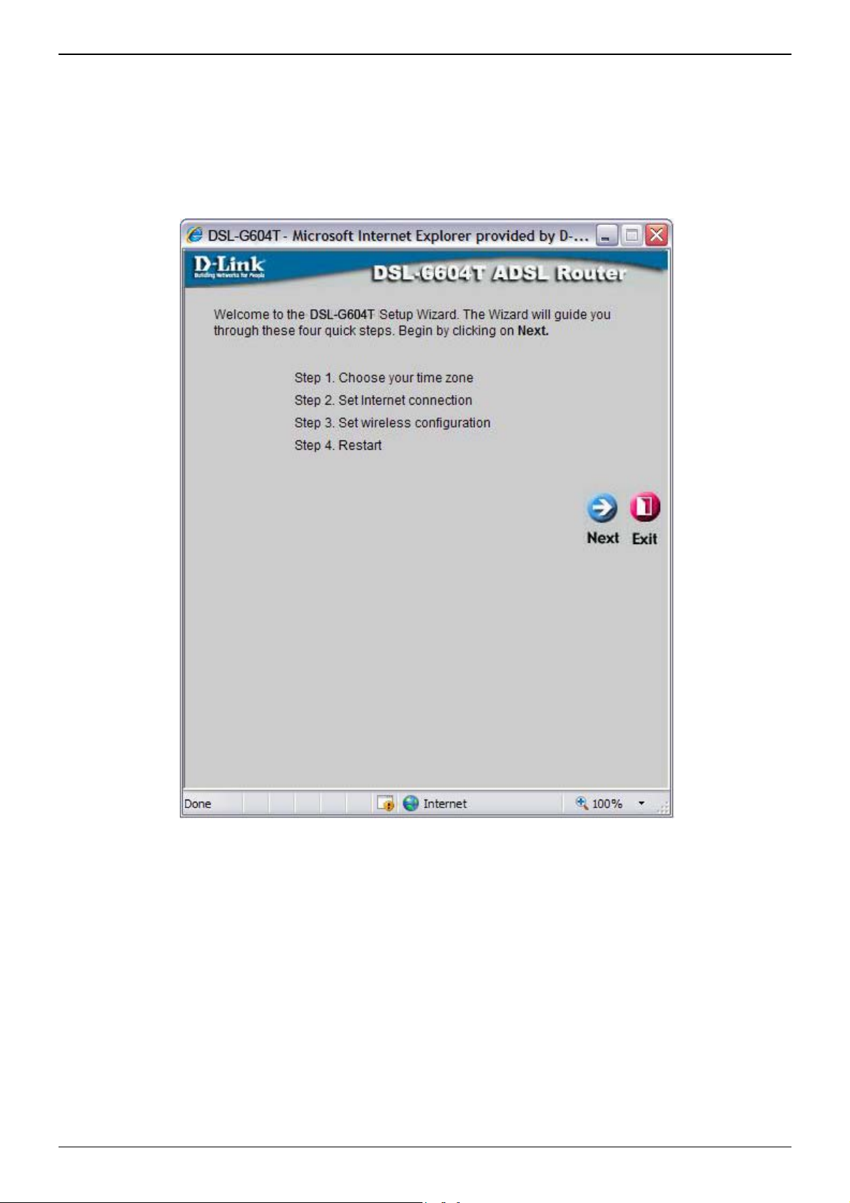
Wizard
To use the Setup Wizard, click the Run Wizard button in the first browser window and follow the instructions in
the pop-up window that appears.
The initial window summarizes the setup process. Click the Next button to proceed. You may stop using the
Setup Wizard at any time by clicking the Exit button. If you exit the wizard you will return to the Setup
Wizard window without saving any of the settings changed during the process.
The first pop-up window of the Setup Wizard lists the basic steps in the process. These steps are as follows:
1. Set the system time.
2. Configure the connection to the Internet.
3. Save the new configuration settings and reboot the system.
Page 20 of 110 www.dlink.com.au
Page 21
DSL-G604T Generation II ADSL2+ Wireless Modem Router
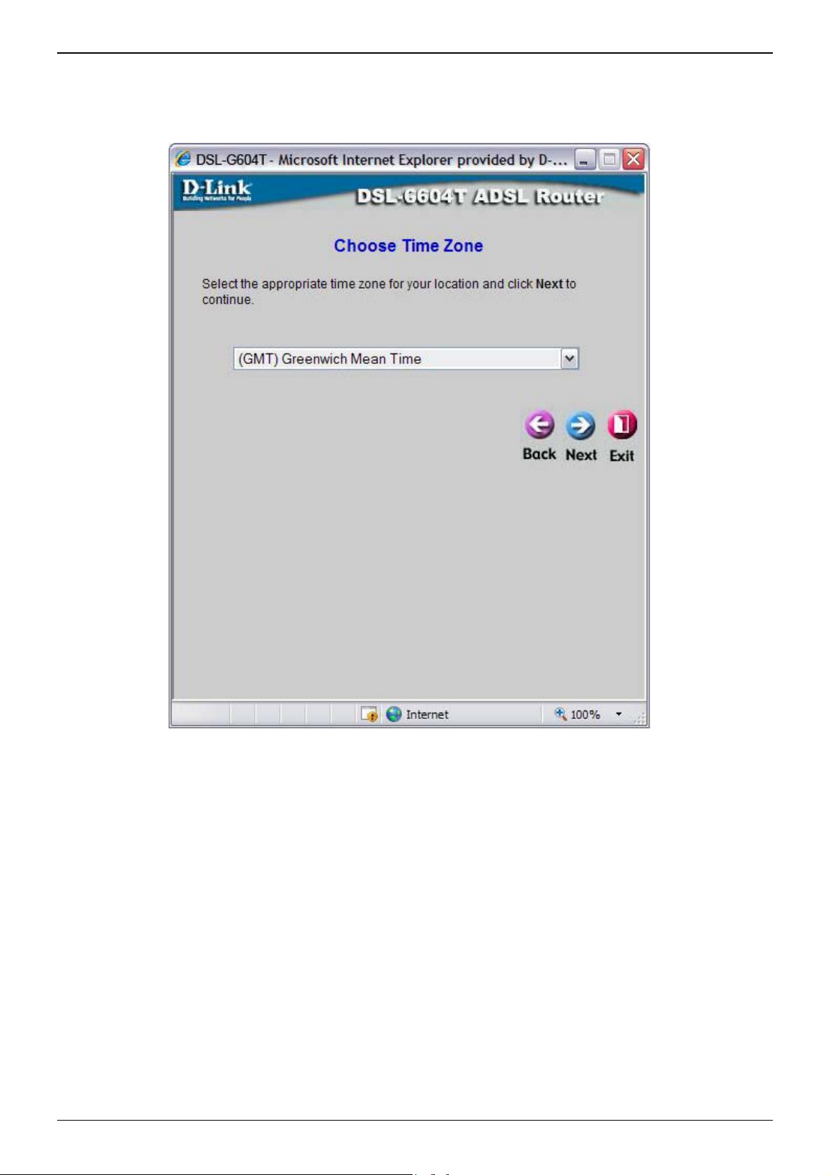
Using the Setup Wizard - Choose Time Zone
Choose the time zone you are in from the pull-down menu and click Next. This sets the system time used for
the Router. If you wish to return to the previous window during the setup process, click the Back button.
Page 21 of 110 www.dlink.com.au
Page 22

DSL-G604T Generation II ADSL2+ Wireless Modem Router
Using the Setup Wizard - Choose Connection Type
Now select the Connection Type used for the Internet connection. Your ISP has given this information to you.
The connection types available for “Multi-User” Mode are PPPoE/PPPoA, Dynamic IP Address, Static IP
Address, and Bridge Mode. Each connection type has different settings that are configured in the next Setup
Wizard pop-up window.
Select the Connection Type specific to your service and click Next to go to the next Setup Wizard pop-up
window. Follow the instructions below for the type of connection you have selected.
Page 22 of 110 www.dlink.com.au
Page 23
DSL-G604T Generation II ADSL2+ Wireless Modem Router
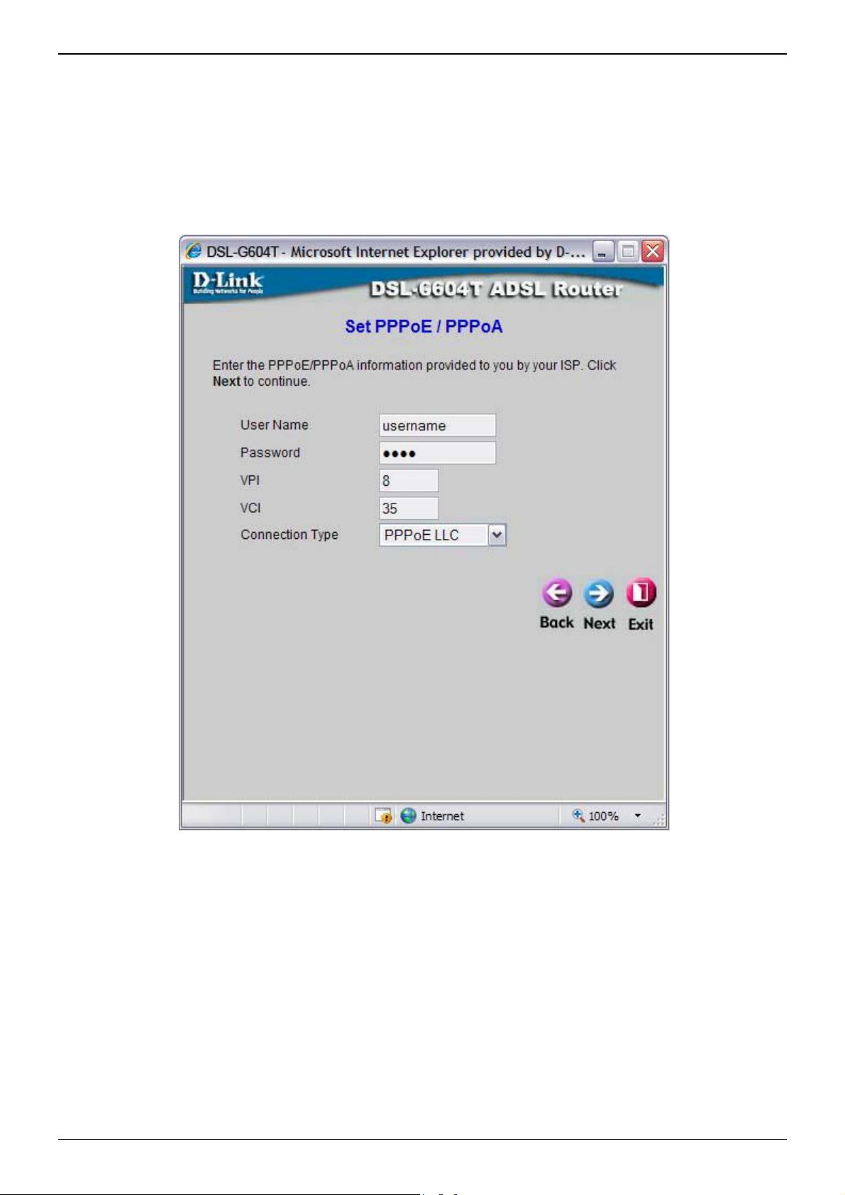
Using the Setup Wizard - For PPPoE/PPPoA connections:
1. Type in the Username and Password used to identify and verify your account to the ISP.
2. Select the specific Connection Type from the drop-down menu. The available PPP connection and
encapsulation types are PPPoE LLC, PPPoA LLC and PPPoA VC-Mux.
3. If you are instructed to change the VPI or VCI number, type in the correct setting in the available entry
fields. Most users will not need to change these settings. The Internet connecti on cannot function if these
values are incorrect.
4. Click Next to go to the next window and complete the Setup Wizard.
Page 23 of 110 www.dlink.com.au
Page 24
DSL-G604T Generation II ADSL2+ Wireless Modem Router
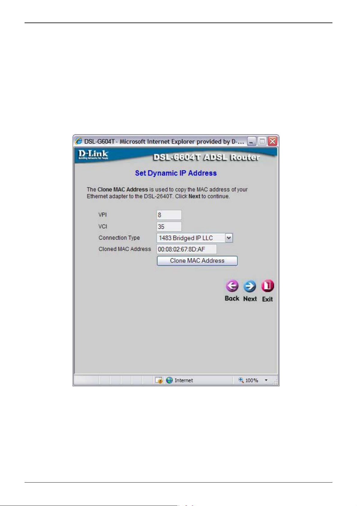
Using the Setup Wizard - For Dynamic IP Address connections:
1. Select the specific Connection Type from the drop-down menu. The available Dynamic IP Address
connection and encapsulation types are 1483 Bridged IP LLC and 1483 Bridged IP VC-Mux.
2. If you are instructed to change the VPI or VCI number, type in the correct setting in the available entry
fields. Most users will not need to change these settings. The Internet connection cannot function if these
values are incorrect.
3. You may want to copy the MAC address of your Ethernet adapter to the Router. Some ISPs record the
unique MAC address of your computer’s Ethernet adapter when you first access their network. This can
prevent the Router (which has a different MAC address) from being allowed access to the ISPs network
(and the Internet). To clone the MAC address of your computer’s Ethernet adapter, type in the MAC address
in the Cloned MAC Address field and click the Clone MAC Address button. This will copy the information to
a file used by the Router to present to the ISP’s server used for DHCP.
4. Click Next to go to the next pop-up window and complete the Setup Wizard.
Page 24 of 110 www.dlink.com.au
Page 25
DSL-G604T Generation II ADSL2+ Wireless Modem Router
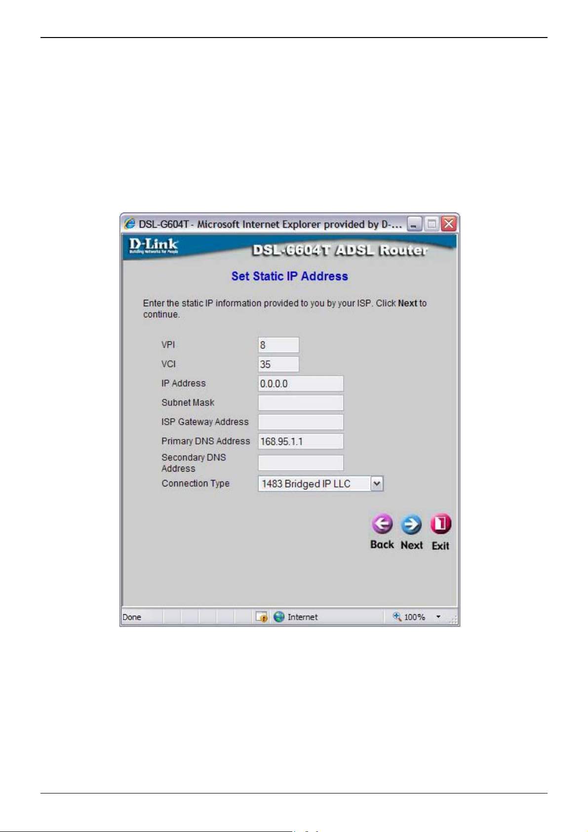
Using the Setup Wizard - For Static IP Address connections:
1. Select the specific Connection Type from the drop-down menu. The available Static IP Address connection
and encapsulation types are 1483 Bridged IP LLC, 1483 Bridged IP VC-Mux, 1483 Routed IP LLC, 1483
Routed IP VC-Mux and IPoA.
2. Change the IP Address, Subnet Mask, ISP Gateway Address, Primary DNS Address, and Secondary
DNS Server IP Address as instructed by your ISP. For IPoA connections it may also be necessary to
change the ARP Server Address. IPoA connection users who have not been given this information should
leave the field blank.
3. If you are instructed to change the VPI or VCI number, type in the correct setting in the available entry
fields. Most users will not need to change these settings. The Internet connection cannot function if these
values are incorrect.
4. Click Next to go to the next window and complete the Setup Wizard.
Page 25 of 110 www.dlink.com.au
Page 26
DSL-G604T Generation II ADSL2+ Wireless Modem Router
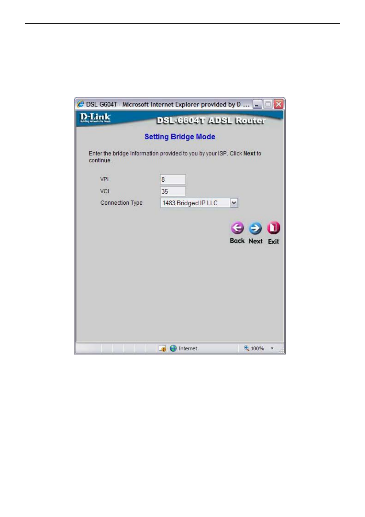
Using the Setup Wizard - For Bridge Mode connections:
1. Select the specific Connection Type from the drop-down menu. The available Bridge Mode connection and
encapsulation types are 1483 Bridged IP LLC and 1483 Bridged IP VC-Mux.
2. If you are instructed to change the VPI or VCI number, type in the correct setting in the available entry
fields. Most users will not need to change these settings. The Internet connection cannot function if these
values are incorrect.
3. Click Next to go to the next window and complete the Setup Wizard.
Page 26 of 110 www.dlink.com.au
Page 27
DSL-G604T Generation II ADSL2+ Wireless Modem Router
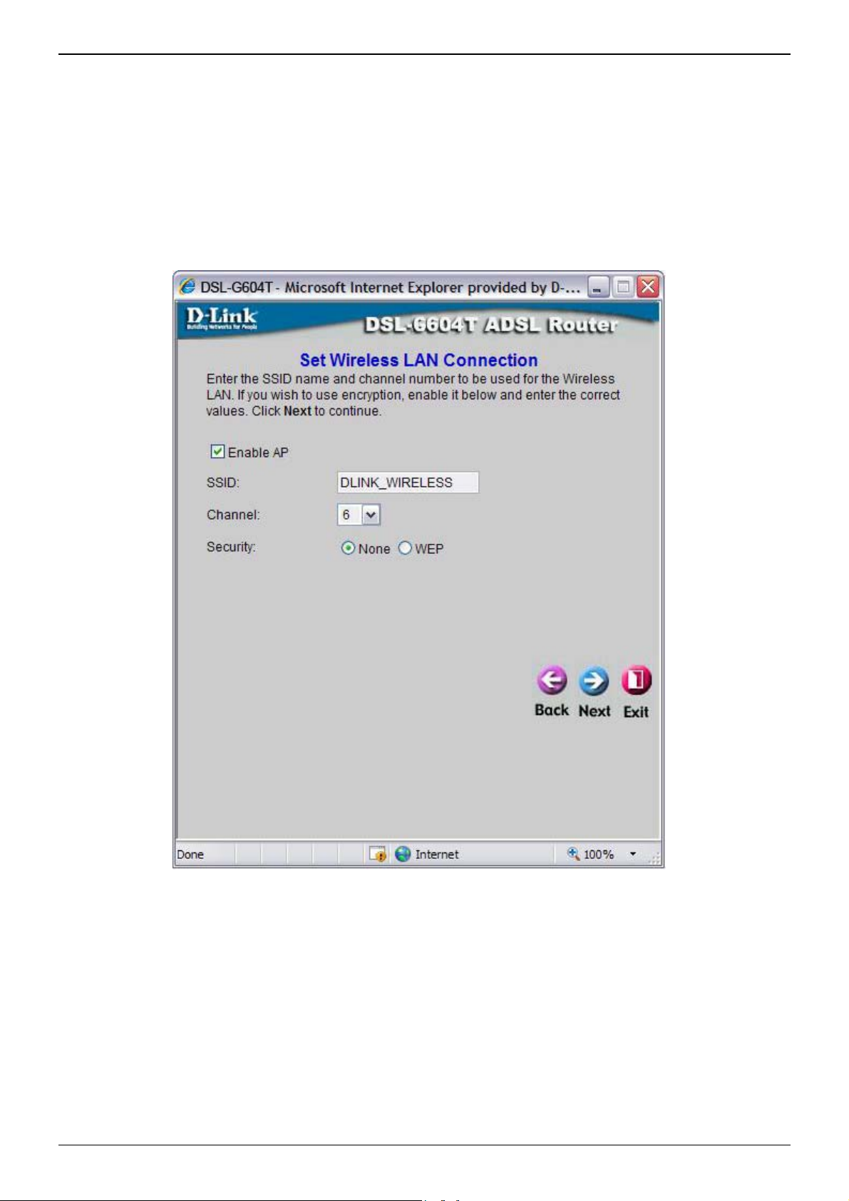
Using the Setup Wizard - Wireless LAN Configuration
Configure the SSID and Channel for the Wireless LAN. You may also configure WEP security settings at this
time or configure them later using the web manager. Select None to configure WEP later. To disable the
wireless access point, click the Enable AP option box to remove the green check mark. To configure Wirless
LAN settings:
1. Enter the SSID for the Wireless LAN
2. Choose the wireless Channel to be used for your WLAN from the pull down menu.
3. Choose the wireless security setup. If WEP is used an additional step is required for configuration
4. Click Next
Page 27 of 110 www.dlink.com.au
Page 28
DSL-G604T Generation II ADSL2+ Wireless Modem Router
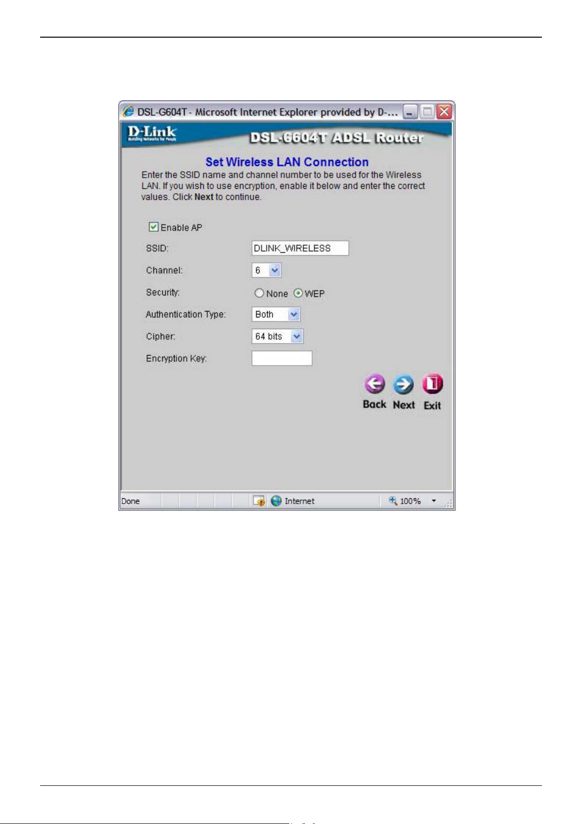
Using the Setup Wizard - WEP Configuration
If you are configuring WEP security, select the Authentication Type, Cipher rate and Encryption Key. Click
Next to continue to the final menu.
Page 28 of 110 www.dlink.com.au
Page 29
DSL-G604T Generation II ADSL2+ Wireless Modem Router
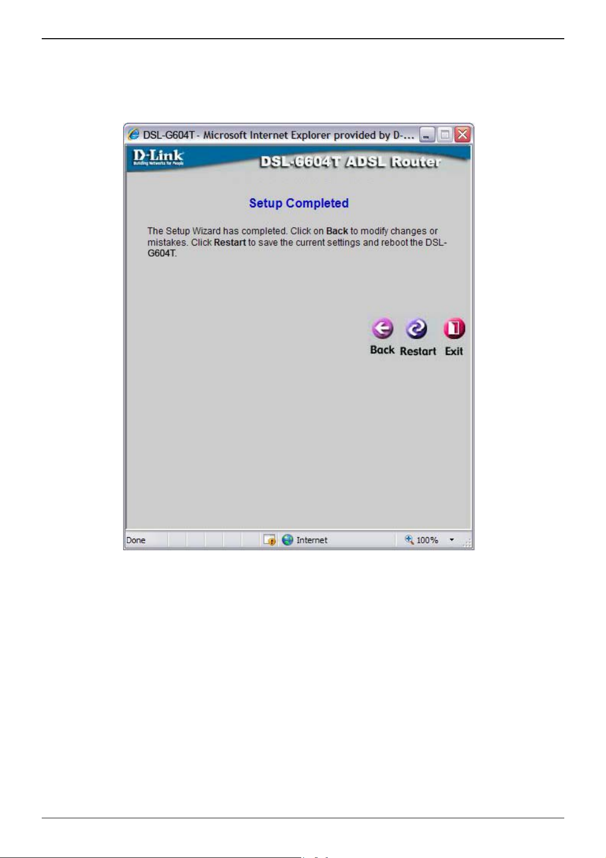
Using the Setup Wizard - Finish and Restart
Finally you can confirm that the setup process is completed. If you are satisfied that you have entered all the
necessary information correctly, click the Restart button to save the new configuration settings and restart the
Router. If you need to change settings from a previous window, click the Back button.
Do not turn the Router off while it is restarting. After the Router is finished restarti ng, you are now ready
to continue to configure the Router as desired. You may want to test the WAN connection by accessing the
Internet with your browser.
Page 29 of 110 www.dlink.com.au
Page 30
W
winHothe
e
0
s
t
r
E
t
n
r
e
u
.
D
r
e
b
a
a
v
a
r
i
s
DSL-G604
T
g
,
e
o
t
h
t
s
u
t
y
c
t
g
t
o
S
c
t
e
u
N
c
h
–
e
e
s
r
o
t
n
W
a
y
p
s
k
h
t
)
t
r
W
n
n
t
u
a
A
w
r
m
S
r
u
T
o
e
e
s
Generation
II ADSL2+
Wireless M
dem Route
ireles
To
configure
dows used
me directo
first windo
he Router’s
to configu
y. To acces
w that appe
basic confi
e Wireless
s the Wirel
ars when y
uration se
WAN, LAN
ss Settin
u successfu
tings witho
, DHCP, D
s window,
lly access t
t running
S, and Dy
lick on the
e web man
he Setup
amic DNS
ireless li
ger.
izard, you
settings di
k button on
can access
ectly from
the left sid
the
the
of
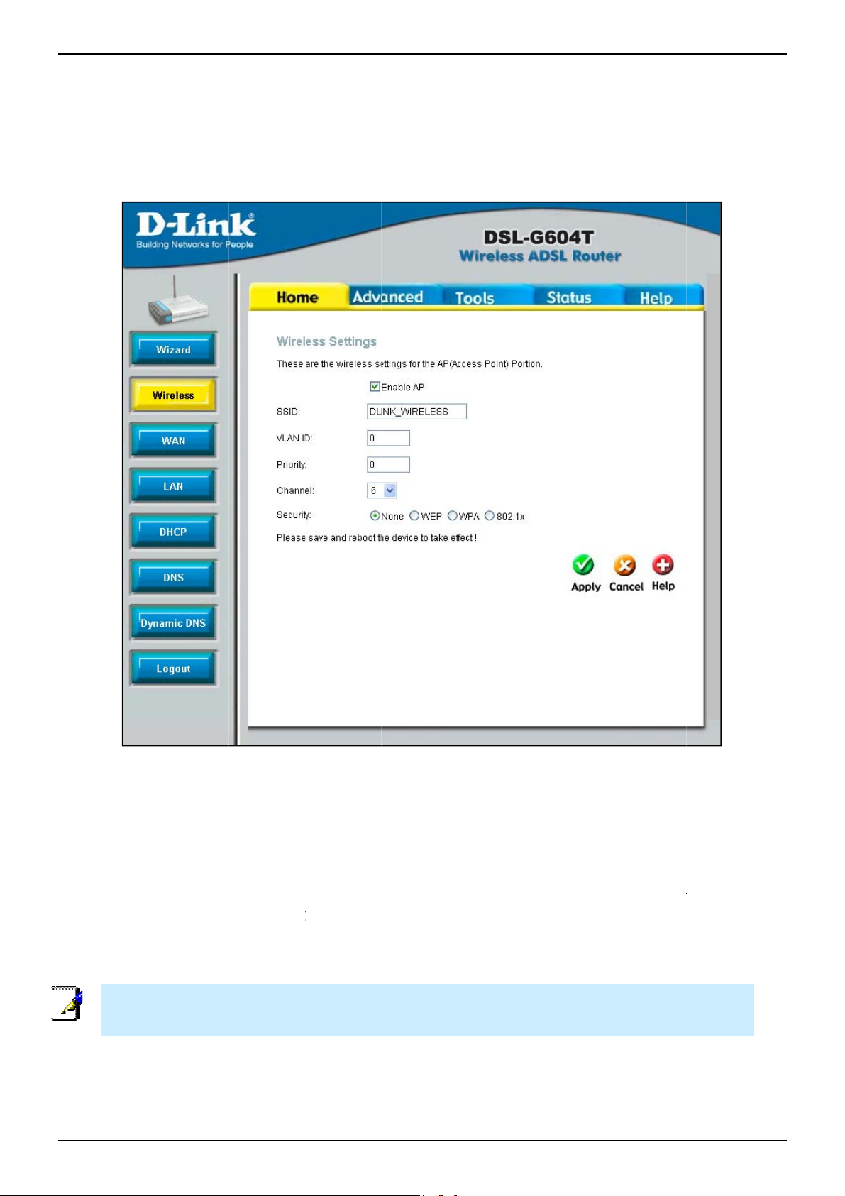
r Basic Wire
Fo
Click the
1.
The SSID
2.
the defaul
What cha
3.
Remembe
SSID). Us
channel n
The VLAN
4.
(IEEE 802
5.
If network
Not
Pa
ge 30 of 11
VLAN I
less LAN op
nable AP
identifies m
SSID is ch
nels are av
that all de
the drop-d
mber is av
ID and Prio
11p), type
Security i
and Priority
ration with
ox to allow
embers of t
nged, all o
ilable for u
ices comm
own menu
ilable from
ity settings
n the appro
not used,
settings do n
Wireless Se
no Securtiy
he router t
e Service
her devices
e by the ac
nicating wi
o select the
our Intern
are optional
priate value
lick to selec
ot need to be
tings menu
settings, fo
operate in
et. Accept t
on the wire
ess point d
h the devic
Channel u
t Service P
settings. If
s here.
t None, the
configured in
No Securit
llow the ste
the wireles
he default n
less networ
pends on t
must use
ed for your
ovider (ISP
your netwo
n click Appl
order to use
s:
environme
ame or cha
must use
e local reg
he same ch
802.11g wi
.
rk supports
y.
he Wireless
nt.
ge it to so
he same S
latory envi
nnel (and
reless LAN.
VLANs or Q
ccess Point.
ww
ething else
ID.
onment.
se the sam
he wireles
S Priority
.dlink.com
. If
.au
Page 31

DSL-G604T Generation II ADSL2+ Wireless Modem Router
Wireless Security
In the Wireless Settings window, select the type of security you want to configure. The window will change to
present the settings specific to the method being configured. The Router’s wireless security options include
three levels of WEP encryption, WPA for IEEE 802.1x network authentication, and WPA with a user-configured
Pre Shared Key (PSK).
WEP
WEP (Wired Equivalent Protocol) encryption can be enabled for security and privacy. WEP encrypts the data
portion of each frame transmitted from the wireless adapter using one of the predefined keys. The router offers
64-, 128-, or 256-bit encryption with four keys available.
To bring up the Wireless Settings window for WEP, click the WEP radio button.
Wireless Settings menu – WEP
1. Make sure the Enable AP checkbox at the top of the window has been checked.
2. Click the Enable WEP Wireless Security checkbox.
3. From the drop-down menu, select an Authentication Type: Open, Shared, or Both.
4. Select a key by clicking a radio button on the left, select an encryption level from the drop-down menu on
the right, and then enter the proper-length key. (Key length is outlined at the bottom of the window.)
5. Click Apply.
Notice If encryption of any kind, at any level is applied to the Wireless network, all devices on th e network
must comply with all security measures.
Page 31 of 110 www.dlink.com.au
Page 32
DSL-G604T Generation II ADSL2+ Wireless Modem Router
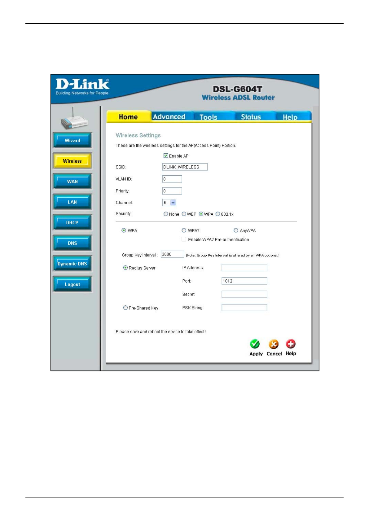
WPA (Wi-Fi Protected Access)
Wi-Fi Protected Access was designed to provide improved data encryption, perceived as weak in WEP, and to
provide user authentication, largely nonexistent in WEP. There are two versions of WPA, both are supported by
the Access Point. WPA includes the option of using a Pre-Shared Key similar to WEP, or a RADIUS server can be
used for varification.
Wireless Settings menu – WPA
1. Make sure the Enable AP checkbox at the top of the window has been checked.
2. Click to select the WPA radio button.
3. In the Group Key Interval entry field, enter a Time (in seconds) after which the Group Key is changed
automatically.
4. Select either Radius Server or Pre-Shared Key depending on the varification you are using for the
Wireless network.
5. If you are using a Radius Server for authentication, select the Radius Server button and enter the server
IP Address of the RADIUS server, a Port number (or accept the default), and a “Shared” Secret (1-63
characters).
6. If you are using a Pre-Shared Key, type an alphanumeric value of 1-63 characters in length used for
authentication.
7. Click Apply.
Page 32 of 110 www.dlink.com.au
Page 33

DSL-G604T Generation II ADSL2+ Wireless Modem Router
802.1x
Some network-security experts now recommend that wireless networks use 802.1X security measures to
overcome some weaknesses in standard WEP applications. A RADIUS server is used to authenticate all potential
users. Configure the following:
Server IP Address: Enter the IP address of the Radius server.
Port: Enter a port number, or accept the default.
Secret: Enter a password (1-63 character).
Group Key Interval: Time (in seconds) after which the Group Key is changed automatically (1-99999).
Wireless Settings menu– 802.1x
1. Make sure the Enable AP checkbox at the top of the window has been checked.
2. Click to select the 802.1x radio button.
3. In the Group Key Interval entry field, enter a Time (in seconds) after which the Group Key is changed
automatically.
4. Enter the Server IP Address of the RADIUS server.
5. Enter a Port number, or accept the default.
6. Enter a password or “Shared” Secret (1-63 characters).
7. Click Apply.
Page 33 of 110 www.dlink.com.au
Page 34

W
winWAsuc
P
Ma
o
eCome
cste
t
N
0
AN
t
c
P
t
E
n
S
r
e
e
P
P
s
v
o
s
n
a
e
c
e
f
W
d
d
a
i
h
t
P
P
t
e
S
t
y
o
r
P
t
a
T
g
,
W
g
n
a
t
E
e
g
A
t
e
t
A
A
g
t
t
t
u
i
t
a
u
t
W
o
E/
f
e
t
u
g
e
e
t
w
e
e
e
o
t
r
h
A
h
f
o
g
g
a
r
W
m
d
e
S
t
g
o
g
r
w
w
y
p
y
f
s
y
e
e
a
D
To
configure
dows used
N Settings
cessfully a
P
PoE/PP
Fo
llow the ins
to
use a PPPo
ke sure yo
be
fore you co
st users wi
M
th
settings
nnection
nu. This a
in
the exampl
se
tion can b
p-by-step i
se
tings for a
ote
To
configure a
Mo
con
the
squ
he Router’s
to configur
window, cli
cess the w
oA
ructions bel
or PPPoA
u have all
figure the
ll only nee
listed un
etting he
ea is conta
to the rig
seen on
nstructions
PPoE or PP
t users with
ections only
settings caon
re in this ex
PPPoE or P
DSL-G604
basic confi
WAN, LAN
k on the
b manager.
ow to confi
or the Inter
the necess
AN connec
to change
er PPPo
ding in th
ned within
t. An enlar
he next pa
on how to
oA connect
PPoE/PPPo
need to confi
ained within
mple menu.
PoA type W
Generation
uration se
DHCP, and
AN link but
ure the Ro
et connect
ry informa
ion.
some or al
/PPPoA
WAN setti
the red sq
ed view of
ge followed
configure
ion.
ure
he red
N connecti
II ADSL2+
tings witho
DNS settin
on on the l
ter
on.
ion
l of
nd
ngs
are
his
by
AN
W
n, follow th
Wireless M
t running
s directly f
ft side of t
W
se steps:
dem Route
he Setup
om the Ho
e first win
N
Settings m
izard, you
e director
ow that ap
nu – PPPoE/
can access
. To access
ears when
PPPoA
the
the
ou
1.
If not alr
PPPoE/PP
Under the
2.
instructed
values as
Enabled)
service. F
Pa
ge 34 of 11
eady selec
oA is select
ATM VC
to change
igned for
alues for n
r more info
ed, choose
d by defaul
ettings a
hem. How
our accoun
w. This can
mation on
the PPPo
t if you are
the top o
ver, if you
. Leave th
be used lat
TM VC Set
PPPoA opt
configuring
the windo
are instruct
PVC and
er if you ar
ings, see th
ion from t
he Router
should n
d to chan
Virtual Cir
configurin
table on p
e WAN
or the first
t be chan
e the VPI
cuit settin
multiple vi
ge 46 belo
ettings pu
ime.
ed unless
r VCI valu
at the de
rtual circuit
.
ll-down m
ou have b
es, type in
ault (Pcv0
for your A
ww
.dlink.com
nu.
en
the
nd
SL
.au
Page 35

DSL-G604T Generation II ADSL2+ Wireless Modem Router
3. Under the PPPoE/PPPoA heading, type the User Name and Password used for your ADSL account. A
typical User Name will be in the form user1234@isp.com.au. The Password may be assigned to you by your
ISP or you may have selected it when you set up the account with your ISP.
4. Choose the correct Authentication Type from the drop-down menu. Most users will want to leave the
setting on Auto. PAP and CHAP are the other two opti ons. The Auto setting will automatically detect the
correct type of authentication.
5. Choose the Connection Type from the pull-down menu located under the User Name and Password entry
fields. This defines both the connection protocol and encapsulation method used for your ADSL service. The
available options are PPPoA VC-Mux, PPPoA LLC and PPPoE LLC. If have not been provided specific
information for the Connection Type setting, leave the default setting.
6. Leave the MTU value at the default setting (default = 1400) unless you have specific reasons to change
this (see table below for more information).
7. Leave the MRU value at the default setting (default = 1492) unless you have specific reasons to change
this (see table below for more information).
8. Leave the Default Route enabled if you want to use the Router as the default route to the Internet for
your LAN. Whenever a computer on the LAN attempts to access the Internet, the Router becomes the
Internet gateway to the computer. If you have an alternative route for Internet traffic you may disable this
without effecting the Router’s connection.
9. Enable PPPoE PassThrough if you want the Router to allow a “dial-up” or separate bridged PPP connection
to an individual PC (see table below for more information).
10. NAT should remain Enabled. If you disable NAT, you will not be able to use more than one computer for
Internet connections. If you are using multiple virtual connections, NAT functions system-wide, therefore if
it is disabled, NAT will be disabled on all connections.
11. The Firewall should remain enabled for most users. If you choose to disable this you will not be able to use
the features configured in the Firewall Configuration and Filters windows located in the Advanced
directory. The next chapter contains a separate section describing these Advanced features.
12. Typically the globally IP settings (i.e. IP address for the WAN i nterface) for a PPPoA or PPPoA connection
will use Dynamic IP assignment from the ISP. Some accounts may be assigned a specific global IP address.
If you have been give an IP address for you PPPoE/PPPoA connection, select the Static IP option from the
IP Control pull-down menu. This menu can be used to configure the WAN port as an Unnumbered IP
interface. (See table below for information on Unnumbered IP).
13. Choose the desired Connection Setting. Select from: Always ON, Connection On Demand, or Manual.
Most users will want to choose the default connection setting, Always ON.
14. Point-to-Point Tunneling Protocol is a pass-through mechanism that allows packets to pass through the
Router so that it effectively functions as a bridge. Check Enable PPTP and enter the requi red information
in the ServerIP/Name, Route Target, Route Mask, PPTP Account, PPTP Password, and MPPE
Encryption fields.
15. Most users will not need to change ATM settings. If this is the first time you are setting up the ADSL
connection it is recommended that you leave the Service Category settings at the default values until you
have established the connection. See the table on page 44 for a description of the parameters available for
ATM traffic shaping.
16. When you are satisfied that all the WAN settings are configured correctly, click on the Apply button.
17. The new settings must be saved and the Router must be restarted for the settings to go into effect. To save
and reboot the Router, click on the Tools directory tab and then click the System button. In the System
Settings window, click the Save and Reboot button under Save Settings and Reboot the System.
18. Click OK when the following “Save and restart?” dialog box opens.
19. The Router will save the new settings and restart. Upon restarting the Router will automatically establish
the WAN connection.
Page 35 of 110 www.dlink.com.au
Page 36

DSL-G604T Generation II ADSL2+ Wireless Modem Router
Additional settings for PPPoE/PPPoA connections:
PPPoE/PPPoA
Description
Parameters
User Name For PPP connections, a User Name and Password are used to identify and verify your
account to the ISP. Enter the User Name for your ADSL service account. User names and
passwords are case-sensitive, so enter this information exactly as given to you by your
ISP.
Password Together with the User Name, this is used to verify your account to the ISP. Enter the
Password exactly as given to you by your ISP.
Connection Type This specifies the protocol (PPPoE or PPPoA) and the encapsulation method (LLC or VC-
Mux) used for your connection. The options available are
VC-Mux
MTU The Maximum Transmission Unit size may be changed if you want to optimize efficiency
for uploading data through the WAN interface. The default setting (
suitable for most users. Some user may want to adjust the setting to optimize
performance for wireless traffic or when low latency is desired (such as with Internet
gaming). It is highly recommended that the user research how adjusting the MTU may
effect network traffic for better or worse.
MRU Similar to the MTU, except this applies to Maximum Received Unit size for downloading
data. Most users will be happy with the default setting (
also be optimized for fast downloads of general bulk Internet traffic, for low latency or for
downloading to computers on the Wireless LAN. As with the MTU setting, the user should
carefully consider how changing the MRU may affect Internet downloads for all systems
on your LAN.
Default Route When this is enabled, the Router will be considered to be the primary gateway to the
Internet and WAN for systems on your network. If you are using the Router on a network
with one or more alternative gateway routers, you may prefer to disable this if you will
use another router as the primary gateway.
PPPoE PassThrough This feature enables the Router to allow a “dial-up” or separate bridged PPP connection to
an individual PC. In this instance the Router will serve as a bridge.
NAT Network Address Translation may be enabled or disabled with the pull-down menu. Keep
in mind that disabling NAT allows only a single computer to be used for Internet access
through the Router. NAT is enabled and disabled for the Router on all connections (i.e.
Pvc0 – Pvc7) if your Router is set up for multiple virtual connections.
Firewall Use this to universally enable or disable the Firewall and Filter features available in the
Router. If you disable this you will not be able to configure settings in the Firewall
Configuration window or Filters window in the Advanced directory.
IP Control This is used to determine how global IP settings are handled for the WAN interface.
Typically PPPoE or PPPoA connections will use the default setting for
users will be given a specific IP address for the WAN interface. In this case you need to
change this setting to
need to type in the global IP address provided to you by your ISP. The
option is used if you want to set up a non-TCP/IP port protocol link through the WAN
interface. An IP Unnumbered interface does not have an IP address and therefore cannot
be managed via Telnet or any other TCP/IP application.
Static IP If you have selected the
address used for your WAN interface. Your ISP should provide this IP address to you.
Connection Setting Select the desired option: Always ON, Connection On Demand, or Manual. Most users will
want to choose the default connection setting, Always ON.
.
Static IP
Static IP
. When Static IP is selected in the IP Control menu, you
option in the IP Control menu, type in the global IP
PPPoE LLC, PPPoA LLC
1400
bytes) should be
1492
bytes). However this may
Dynamic IP
IP Unnumbered
or
PPPoA
. Some
Page 36 of 110 www.dlink.com.au
Page 37

DSL-G604T Generation II ADSL2+ Wireless Modem Router
Dynamic IP Address
A Dynamic IP Address connection configures the Router to automatically obtain its global IP address from a
DHCP server on the ISP’s network. The service provider assigns a global IP address from a pool of addresses
available to the service provider. Typically the IP address assigned has a long lease time, so i t will likely be the
same address each time the Router requests an IP address.
To configure a Dynamic IP Address connection, perform the steps listed below. Some of the settings do not
need to be changed the first time the device is set up, but can be changed later if you choose. See the table
below for a description of all the settings available in this window.
WAN Settings window – Dynamic IP Address
Page 37 of 110 www.dlink.com.au
Page 38

DSL-G604T Generation II ADSL2+ Wireless Modem Router
To configure a Dynamic IP Address connection for the WAN, follow these steps:
1. Choose the Dynamic IP Address option from the WAN Settings pull-down menu.
2. Under the ATM VC Settings at the top of the window should not be changed unless you have been
instructed to change them. However, if you are instructed to change the VPI or VCI values, type in the
values assigned for your account. Leave the PVC and Virtual Circuit setting at the default (Pcv0 and
Enabled) values for now. This can be used later if you are configuring multiple virtual circuits for your ADSL
service. For more information on ATM VC Settings, see the table on page 46 below.
3. Under the Dynamic IP heading, choose the Connection Type from the pull-down menu. This defines both
the connection type and encapsulation method used for your ADSL service. The available options are 1483
Bridged IP LLC and 1483 Bridged IP VC-Mux. If have not been provided specific information for the
Connection Type setting, leave the default setting.
4. Some ISPs record the unique MAC address of your computer’s Ethernet adapter when you first access their
network. This can prevent the Router (which has a different MAC address) from being allowed access to the
ISPs network (and the Internet). To clone the MAC address of your computer’s Ethernet adapter, type in
the MAC address in the Cloned MAC Address field and click the Clone MAC Address button.
5. Leave the MTU value at the default setting (default = 1400) unless you have specific reasons to change
this (see table below).
6. NAT should remain Enabled. If you disable NAT, you will not be able to use more than one computer for
Internet connections. NAT is enabled and disabled system-wide, therefore if you are using multiple virtual
connections, NAT will disabled on all connections.
7. The Firewall should remain enabled for most users. If you choose to disable this you will not be able to use
the features configured in the Firewall Configuration and Filters windows located in the Advanced
directory. See the next chapter for more details on these windows.
8. Most users will not need to change ATM settings. If this is the first time you are setting up the ADSL
connection it is recommended that you leave the Service Category settings at the default values until you
have established the connection. See the table on page 44 for a description of the parameters available for
ATM traffic shaping.
9. When you are satisfied that all the WAN settings are configured correctly, click on the Apply
10. The new settings must be saved and the Router must be restarted for the settings to go into effect. To save
and reboot the Router, click on the Tools directory tab and then click the System button. In the System
Settings window, click the Save and Reboot button under Save Settings and Reboot the System.
11. Click OK when the following “Save and restart?” dialog box opens.
button.
12. The Router will save the new settings and restart. Upon restarting the Router will automatically establish
the WAN connection.
Page 38 of 110 www.dlink.com.au
Page 39

DSL-G604T Generation II ADSL2+ Wireless Modem Router
Additional settings for Dynamic IP Address connections:
Dynamic IP Parameters Description
Connection Type
Cloned MAC Address
Cloned MAC Address
MTU
NAT
Firewall
This specifies the connection type and encapsulation method used for your Dynamic IP
Address connection. The options available are
This is not always necessary, but may be required for some ISPs. Type in the MAC address
of your computer’s Ethernet adapter in the Cloned MAC Address field and click the Clone
MAC Address button. This will copy the information to a file used by the Router to
present to the ISP’s server used for DHCP. Some ISPs record the unique MAC address of
your computer’s Ethernet adapter when you first access their network. If you want to later
replace the cloned MAC address with the factory default setting, type in all zeros 00:00:00:00:00:00 - and click the Clone MAC Address button.
To clone the MAC address of your computer’s Ethernet adapter, type in the MAC address in
the Cloned MAC Address field and then click this Clone MAC Address button.
The Maximum Transmission Unit size may be changed if you want to optimize efficiency for
uploading data through the WAN interface. The default setting (1400 bytes) should be
suitable for most users. Some user may want to adjust the setting to optimize performance
for wireless traffic or when low latency is desired (such as with Internet gaming). It is
highly recommended that the user research how adjusting the MTU may affect network
traffic for better or worse.
Network Address Translation may be enabled or disabled with the pull-down menu. Keep in
mind that disabling NAT allows only a single computer to be used for Internet access
through the Router. NAT is enabled and disabled for the Router on all connections (i.e.
Pvc0 – Pvc7) if your Router is set up for multiple virtual connections.
Use this to universally enable or disable the Firewall and Filter features available in the
Router. If you disable this you will not be able to configure settings in the Firewall
Configuration window or Filters windows in the Advanced directory.
Bridged IP LLC
or
Bridged IP VC-Mux
.
Page 39 of 110 www.dlink.com.au
Page 40

DSL-G604T Generation II ADSL2+ Wireless Modem Router
Static IP Address
When the Router is configured to use Static IP Address assignment for the WAN connection, you must manually
assign a global IP Address, Subnet Mask and Gateway IP Address used for the WAN connection. Most users will
also need to configure DNS server IP settings in the DNS Configuration window (see below). Follow the
instruction below to configure the Router to use Static IP Address assignment for the WAN connection.
To configure a Static IP Address connection, perform the steps listed below. Some of the settings do not need
to be changed the first time the device is set up, but can be changed later if you choose. See the table below
for a description of all the settings available in this window.
WAN Settings window - Static IP
Page 40 of 110 www.dlink.com.au
Page 41

DSL-G604T Generation II ADSL2+ Wireless Modem Router
To configure a Static IP type connection for the WAN, follow these steps:
1. Choose the Static IP Address option from the WAN Settings pull-down menu.
2. Under the ATM VC Settings at the top of the window should not be changed unless you have been
instructed to change them. However, if you are instructed to change the VPI or VCI values, type in the
values assigned for your account. Leave the PVC and Virtual Circuit setting at the default (Pcv0 and
Enabled) values for now. This can be used later if you are configuring multiple virtual circuits for your ADSL
service. For more information on ATM VC Settings, see the table on page 46 below.
3. Under the Static IP heading, choose the Connection Type from the pull-down menu. This defines both
the connection type and encapsulation method used for your ADSL service. The available options are
Bridged IP LLC, Bridged IP VC-Mux, Routed IP LLC, Routed IP VC-Mux or IPoA. If have not been provi ded
specific information for the Connection Type setting, leave the default setting.
4. Change the IP Address, Subnet Mask, Gateway Address and (if available) Secondary DNS Server IP
address as instructed by your ISP. These are the global IP settings for the WAN interface. This is the
“visible” IP address of your account. Your ISP should have provided these IP settings to you. For IPoA
(Classic IP over ATM) connections you may need to type in an additional IP address for a ARP Server
Address. If you are using an IPoA connection, ask your ISP if it is necessary to use an ARP (Address
Resolution Protocol) server.
5. Leave the MTU value at the default setting (default = 1400) unless you have specific reasons to change
this (see table below).
6. NAT should remain Enabled. If you disable NAT, you will not be able to use more than one computer for
Internet connections. NAT is enabled and disabled system-wide, therefore if you are using multiple virtual
connections, NAT will be disabled on all connections.
7. The Firewall should remain enabled for most users. If you choose to disable this you will not be able to use
the features configured in the Firewall Configuration and Filters window located in the Advanced
directory. See the next chapter for more details on these windows.
8. Most users will not need to change ATM settings. If this is the first time you are setting up the ADSL
connection it is recommended that you leave the Service Category settings at the default values until you
have established the connection. See the table on page 44 for a description of the parameters available for
ATM traffic shaping.
9. When you are satisfied that all the WAN settings are configured correctly, click on the Apply button.
10. The new settings must be saved and the Router must be restarted for the settings to go into effect. To save
and reboot the Router, click on the Tools directory tab and then click the System button. In the System
Settings window, click the Save and Reboot button under Save Settings and Reboot the System.
11. Click OK when the following “Save and restart?” dialog box opens.
12. The Router will save the new settings and restart. Upon restarting the Router will automatically establish
the WAN connection.
Page 41 of 110 www.dlink.com.au
Page 42

DSL-G604T Generation II ADSL2+ Wireless Modem Router
Additional settings for Static IP Address connections:
Static IP Parameters Description
Connection Type This specifies the connection type and the encapsulation method used for your Static IP
Address connection. The options available are
,
IP LLC
IP Address This is the permanent global IP address for your account. This is the address that is visible
outside your private network. Get this from your ISP.
Subnet Mask This is the Subnet mask for the WAN interface. Get this from your ISP.
Gateway Address This is the IP address of your ISP’s Gateway router. It provides the connection to the
Router for IP routed traffic that is outside your ISP’s network. That is, this will be the
primary connection from the Router to most of the Internet. Get this IP address from your
ISP.
Routed IP VC-Mux
or
IPoA
.
Bridged IP LLC, Bridged IP VC-Mux, Routed
ARP Server Address
(IPoA connection only)
Primary DNS Address This is the IP address of the first choice for Domain Name Service (DNS) used to match the
Secondary DNS Address This is the second choice for a DNS server. Get this IP address from your ISP.
MTU The Maximum Transmission Unit size may be changed if you want to optimize efficiency for
NAT Network Address Translation may be enabled or disabled with the pull-down menu. Keep in
Firewall Use this to universally enable or disable the Firewall and Filter features available in the
This is not required for all IPoA connections. Check with your ISP for an ARP server IP
address if this is necessary for your IPoA connection.
named URL web address used by most browsers with the actual global IP address used for
a web server. Usually this will be a server owned by the ISP. Get this IP address from your
ISP.
1400
uploading data through the WAN interface. The default setting (
suitable for most users. Some user may want to adjust the setting to optimize performance
for wireless traffic or when low latency is desired (such as with Internet gaming). It is
highly recommended that the user research how adjusting the MTU may affect network
traffic for better or worse.
mind that disabling NAT allows on a single computer to be used for Internet access
through the Router. NAT is enabled and disabled for the Router on all connections (i.e.
Pvc0 – Pvc7) if your Router is set up for multiple virtual connections.
Router. If you disable this you will not be able to configure settings in the Firewall
Configuration window or the Filters window in the Advanced directory.
bytes) should be
Page 42 of 110 www.dlink.com.au
Page 43

DSL-G604T Generation II ADSL2+ Wireless Modem Router
Bridge Mode
The WAN Settings window is also used to configure the Router for multiple virtual connections (Multiple PVCs).
WAN Settings window – Bridge Mode
Select the connection type used for your account. The window will display settings that are appropriate for the
connection type you select. Follow the instruction below according to the type of connection you select in the
WAN Settings window.
For Bridged connections it will be necessary for most users to install additional software on any computer that
will the Router for Internet access. The additional software is used for the purpose of identifying and verifying
your account, and then granting Internet access to the computer requesting the connection. The connection
software requires the user to enter the User Name and Password for the ISP account. This information is stored
on the computer, not in the Router.
Follow the instructions below to configure a Bridged connection for the WAN interface.
To configure a Dynamic IP Address connection, perform the steps listed below. Some of the settings do not
need to be changed the first time the device is set up, but can be changed later if you choose. See the table
below for a description of all the settings available in this window.
Page 43 of 110 www.dlink.com.au
Page 44

DSL-G604T Generation II ADSL2+ Wireless Modem Router
1. Choose the Bridge Mode option from the WAN Settings pull-down menu.
2. Under the ATM VC Settings at the top of the window should not be changed unless you have been
instructed to change them. However, if you are instructed to change the VPI or VCI values, type in the
values assigned for your account. Leave the PVC and Virtual Circuit setting at the default (Pvc0 and
Enabled) values for now. This can be used later if you are configuring multiple virtual circuits for your ADSL
service. For more information on ATM VC Settings, see the table on the page below.
3. Under the Bridge Mode heading, choose the Connection Type from the pull-down menu. This defines
both the connection type and encapsulation method used for your ADSL service. The available options are
1483 Bridged IP LLC and 1483 Bridged IP VC-Mux. If have not been provided specific information for the
Connection Type setting, leave the default setting.
4. Most users will not need to change ATM settings. If this is the first time you are setting up the ADSL
connection it is recommended that you leave the Service Category settings at the default values until you
have established the connection. See the table on the below page for a description of the parameters
available for ATM traffic shaping.
5. When you are satisfied that all the WAN settings are configured correctly, click on the Apply button.
6. The new settings must be saved and the Router must be restarted for the settings to go into effect. To save
and reboot the Router, click on the Tools directory tab and then click the System button. In the System
Settings window, click the Save and Reboot button under Save Settings and Reboot the System.
7. Click OK when the following “Save and restart?” dialog box opens.
8. The Router will save the new settings and restart. Upon restarting the Router will automatically establish
the WAN connection.
ATM Settings - Traffic Shaping
The ATM settings in the WAN Settings windows for the different connection types can be used to adjust QoS
parameters for ADSL clients. This may not be available to all ADSL accounts.
ATM Settings for WAN connection
Page 44 of 110 www.dlink.com.au
Page 45

DSL-G604T Generation II ADSL2+ Wireless Modem Router
The table below provides a description of the ATM settings for traffic shaping.
ATM Parameters Description
Service Category
PCR
SCR
CDVT
MBS
The ATM settings allow the user to adjust ATM Quality of Service (QoS) or traffic parameters to suit
specific traffic requirements. For applications or circumstances where packet loss or packet delay is
a concern, ATM QoS can be adjusted to minimize problems. For most accounts, it will not be
necessary to change these settings. Altering QoS settings can adversely affect performance of some
commonly used Internet applications.
If you plan to change QoS or traffic parameters, contact your ISP or network services provider for
information on what types of adjustment are available or possible for your account. Your ISP may
not support the class of service you want to use.
To adjust ATM QoS parameters, select one of the Service Categories listed here and type in the PCR
value in the entry field below. For the VBR service category, an additional parametre (SCR) must
also be defined.
UBR
– Unspecified Bit Rate, this is the default category used for general-purpose Internet traffic
where normal levels of packet loss and delay are acceptable. For some applications or for multiple
connection accounts, it may be desirable to specify the PCR.
CBR
– Constant Bit Rate, usually used in circumstances where very low packet loss and very low Cell
Delay Variable (CDV) are desirable.
VBR-nt
rates. Please note that when VBR-rt is specified, both PCR and SCR are required (by ATM
standards).
VBR-nrt
bursts of packets at variable intervals, and some moderate packet loss and delay is acceptable. This
category is typically used for audio and video applications such as teleconferencing. The network
must support QoS Class 2 to use VBR-nrt.
– Real-time Variable Bit Rate. This models bursty traffic with specified peak and sustainable
– Non-real-time Variable Bit Rate, usually used when network traffic is characterized by
Peak Cell Rate – The PCR is inversely related to the time interval between ATM cells. It is
specified for all three service categories (UBR, CBR and VBR) in Kbps.
Sustainable Cell Rate – The SCR is defined for the VBR service category. This is the rate that
can be sustained for “bursty”, on-off traffic sources. It is a function of Maximum Burst Size
(MBS) and the time interval (between cells).
Cell Delay Variation Tolerance – CDVT is a measure of the cell clumping phenomenon by which
cells are delayed in the network and are
clumped together and arrive at a system at a faster rate than negotiated.
Increasing the CDVT creates greater bucket depth.
Maximum Burst Size – The MBS is the maximum number of bytes that can be sent
continuously from the source to the destination dropping any packets. Some ATM providers set
the MBS and CDVT very low and adjust up if problems occur.
Page 45 of 110 www.dlink.com.au
Page 46

DSL-G604T Generation II ADSL2+ Wireless Modem Router
ATM VC Settings
ATM VC settings can be configured for all connection types in the WAN configuration menu of the Home
directory.
ATM VC Settings in WAN Settings menu
The table below describes the ATM VC settings used to configure a PPPoE or PPPoA connection for an ADSL
account.
ATM VC Parameters Description
PVC The Router supports using up to eight multiple virtual connections. This window allows
the user to configure WAN settings for all the available connections (see instructions
below on how to set up Multiple Virtual Connections). Use the PVC drop-down menu
to select the connection (Pvc0 to Pvc7) you want to configure. Since most users will
Pvc0
use only a single connection, the default setting
made to the WAN settings.
VPI The Virtual Path Identifier is used with the VCI to define a dedicated circuit on the
ATM network portion of the connection to the Internet and WAN. Most users will not
need to change this setting.
VCI The Virtual Channel Identifier is used with the VPI to define a dedicated circuit on the
ATM network portion of the connection to the Internet and WAN. Most users will not
need to change this setting.
Virtual Circuit As with the PVC setting, this is mainly for use by clients who are configuring the
Router for multiple virtual connections. Use this to enable or disable the PVC you are
currently configuring. By default, the Pvc0 is
Enabled
disabled.
can be used for any changes
and the remaining PVCs are
Page 46 of 110 www.dlink.com.au
Page 47

DSL-G604T Generation II ADSL2+ Wireless Modem Router
LAN
You can configure the LAN IP address to suit your preference. Many users will find it convenient to use the
default settings together with DHCP service to manage the IP settings for their private network. The IP address
of the Router is the base address used for DHCP. In order to use the Router for DHCP on your LAN, the IP
address pool used for DHCP must be compatible with the IP address of the Router. The IP addresses available
in the DHCP IP address pool will change automatically if you change the IP address of the Router. See the next
section for information on DHCP setup.
To access the Management IP window, click the LAN button in the Home directory.
Management IP window
To change the LAN IP Address or Subnet Mask, type in the desired values and click the Apply button. Your
web browser should automatically be redirected to the new IP address. You will asked to login again to the
Router’s web manager.
Page 47 of 110 www.dlink.com.au
Page 48

DSL-G604T Generation II ADSL2+ Wireless Modem Router
DHCP
The DHCP server is enabled by default for the Router’s Ethernet LAN interface. DHCP service will supply IP
settings to workstations configured to automatically obtain IP settings that are connected to the Router though
the Ethernet port. When the Router is used for DHCP it becomes the default gateway for DHCP client connected
to it. Keep in mind that if you change the IP address of the Router the range of IP addresses i n the pool used
for DHCP on the LAN will also be changed. The IP address pool can be up to 253 IP addresses.
DHCP Settings window
To display the DHCP Settings window, click the DHCP button in the Home directory. Any active DHCP Clients
appear at the bottom of the window in the DHCP Clients List. The IP address and MAC address for active DHCP
clients are displayed in the list.
The two options for DHCP service are as follows:
You may use the Router as a DHCP server for your LAN.
You can disable DHCP service and manually configure IP settings for workstations.
You may also configure DNS settings for the LAN when using the Router in DHCP mode. In Auto DNS Mode,
the Router will automatically relay DNS settings to properly configured DHCP clients. To manually enter DNS IP
addresses, select the Manual DNS Mode option and type in a Primary and Secondary DNS IP Address in the
field provided. The manually configured DNS settings will be supplied to clients that are configured to request
them from the Router.
Page 48 of 110 www.dlink.com.au
Page 49

DSL-G604T Generation II ADSL2+ Wireless Modem Router
Follow the instructions below according to which of the above DHCP options you want to use. When you have
configured the DHCP Settings as you want them, click the Apply button to commit the new settings.
Use the Router for DHCP
To use the built-in DHCP server, click to select the DHCP Server option if it is not already selected. The IP
Address Pool settings can be adjusted. The Starting IP Address is the lowest available IP address (default =
10.1.1.2). If you change the IP address of the Router this will change automatically to be 1 more that the IP
address of the Router.
The Ending IP Address is the highest IP address number in the pool. Type in the Lease Time in the entry
field provided. This is the amount of time in seconds that a workstation is allowed to reserve an IP address in
the pool if the workstation is disconnected from the network or powered off.
Disable the DHCP Server
To disable DHCP, click to select the No DHCP option and click on the Apply button. Choosing this option
requires that workstations on the local network must be configured manually or use another DHCP server to
obtain IP settings.
If you configure IP settings manually, make sure to use IP addresses in the subnet of the Router. You will need
to use the Router’s IP address as the Default Gateway for the workstation in order to provide Internet access.
DHCP Settings window with DHCP disabled
Page 49 of 110 www.dlink.com.au
Page 50

t
etheleaTo
a
o
0
o
h
r
n
a
o
e
w
p
a
a
g
C
d
e
e
h
U
r
u
o
n
d
s
o
n
DSL-G604
T
n
e
a
m
i
P
s
“
u
m
s
e
r
r
d
c
e
0
e
t
C
0
a
o
c
o
A
w
r
e
e
P
w
t
s
v
t
a
w
o
a
e
m
e
To m
nually config
Wind
ws workstati
Prop
rties menu a
follo
ing IP addres
to su
N
te
Defu
G604
T) for each w
here
settin
ply the IP ad
lt gateway (u
lso uses ma
s.
re IP setting
ns, open the
d select the
s” option. Yo
res, Subnet
e IP addres
rkstation. Th
ually configu
Generation
on
TCP/IP
Use the
will need
ask and
of DSL-
example
ed DNS
II ADSL2+
Wireless M
dem Route
S
atic IP
If
the Router
sp
cified by t
chosen IP
se time for
assign an I
the spaces
in
10
.1.1.xxx fo
t have bee
th
n LAN
has the DH
eir MAC ad
address us
the IP addr
P address t
provided.
the IP add
configured
P server e
ress. Up to
d out of the
ss to the s
at will not
se the for
ess. A Stat
for static I
abled it is
five IP add
available a
lected devi
ge out, typ
at: 00-00-
c DHCP Cli
address as
possible to
esses may
dresses in
e.
in the MA
0-00-00-0
nt List will
signment.
permanentl
e assigned
he dynami
Address
for the M
ppear belo
y assign IP
to five diff
IP address
f the devic
C address
the DHC
addresses
rent device
pool and gi
and its sta
and the st
Client list
o workstati
. This will t
e a perman
ic IP Addr
ndard for
ith any cli
ns
ke
ent
ss
at:
nts
Pa
ge 50 of 11
ww
.dlink.com
.au
Page 51

D
thema
iconIn Dis
r
oSta
e
eWh
0
NS
W
S
N
e
R
N
o
a
o
e
d
o
e
u
r
u
d
e
b
e
e
D
g
d
e
c
T
y
a
s
e
w
e
D
u
N
D
e
A
e
u
e
n
N
h
o
c
r
s
b
e
e
l
u
S
U
r
I
c
t
o
i
D
a
s
R
t
d
N
b
r
t
n
e
N
o
o
h
f
t
w
t
A
e
h
c
O
g
n
n
o
u
U
D
e
Th
e Router ca
on
your LAN.
m to the I
nually ente
LA
N to use D
us
ng DNS s
figured).
n be config
hen using
P’s, or alte
red by the
S servers
rvers on t
DSL-G604
red to rela
DNS relay,
native DNS
ser. Altern
irectly. Mo
he ISP’s n
Generation
DNS setti
the Router
servers. D
tively, you
t users, w
twork, will
II ADSL2+
gs from yo
will accept
S relay can
may also d
o are using
leave DN
Wireless M
r ISP or an
DNS reques
use auto d
isable the
the Router
relay en
dem Route
other availa
ts from hos
scovery or
NS relay a
for DHCP s
bled (eith
ble service
ts on the L
he DNS IP
d configur
ervice on t
r auto dis
o workstati
N and forw
address can
hosts on y
e LAN and
overy or
ns
ard
be
our
are
ser
the DNS
covered D
If
you have n
se
ver inform
R
uter to aut
tic IP addr
If
you have D
Preferre
th
If
you choose
y will not b
th
en you hav
Note
Pa
ge 51 of 11
elay Select
S ServerOn
t been giv
tion, select
matically o
ss, auto dis
NS IP addr
DNS Serv
to Disable
e dependin
e configure
T
use DNS R
th
Firewall se
ion pull-do
ly or Disabl
n specific
the Use A
tain the D
covery for
sses provid
r and the
NS Relay,
on the Rou
the DNS s
lay for comp
tion in the n
DNS C
n menu,
DNS Relay
NS server
to Discove
S IP addre
NS cannot
d by your
lternative
it will be n
ter to forwa
ttings as d
ters on your
xt chapter.
nfiguration
hoose to
.
IP addresse
ed DNS Se
s from the
e used.
ISP, enter t
DNS Serve
cessary to
rd the DNS
sired, click
ocal network,
window
se Auto Di
s or if the
verOnly op
SP through
hese IP ad
r.
onfigure D
requests.
he Apply
DNS Service
covered D
outer is n
ion. Auto d
DHCP. If y
resses in t
S settings
utton.
Filtering mus
S Server
t pre-confi
iscovery DN
ur WAN co
e available
for hosts o
be disabled.
ww
nly, Use
ured with
S instructs
nection us
entry fields
the LAN si
See
.dlink.com
ser
NS
the
s a
for
nce
.au
Page 52

DSL-G604T Generation II ADSL2+ Wireless Modem Router
Dynamic DNS
The Router supports DDNS (Dynamic Domain Name Service). The Dynamic DNS service allows a dynamic public
IP address to be associated with a static host name in any of the many domains, allowing access to a specified
host from various locations on the Internet. This is enabled to allow remote access to a host by clicking a
hyperlinked URL in the form hostname.dyndns.org, Many ISPs assign public IP addresses using DHCP, and this
can make it difficult to locate a specific host on the LAN using standard DNS. If for example you are running a
public web server or VPN server on your LAN, this ensures that the host can be located from the Internet if the
public IP address changes. DDNS requires that an account be setup with one of the supported DDNS providers.
Dynamic DNS Configuration window
Note: DDNS requires that an account be setup with one of the supported DDNS servers prior to engaging it on
the router. This function will not work without an accepted account with a DDNS server.
Enter the required DDNS information and click Apply to set this information in the Router.
DDNS Parameters Description
DDNS Server Select one of the DDNS registration organizations form those listed in the pull-down menu.
Available servers include DynDns.org and No-IP.com.
Username (or Key) Enter the username given to you by your DDNS server.
Password (or Key) Enter the password or key given to you by your DDNS server
Host Name Enter the host name of the DDNS server.
Page 52 of 110 www.dlink.com.au
Page 53

DSL-G604T Generation II ADSL2+ Wireless Modem Router
Save Settings and Reboot
When you have configured the DSL-G604T with the settings you desire, make sure you save those settings. To
save the system configuration settings, click the Tools tab. You will be presented first with the Administrator
Settings window. This window is described in the next chapter. To save the current configuration, click the
System button to view the System Settings window pictured here.
System Settings window
To save the settings you have configured, click the Save and Reboot button under Save Settings and Reboot
the System.
Page 53 of 110 www.dlink.com.au
Page 54

DSL-G604T Generation II ADSL2+ Wireless Modem Router
Multiple Virtual Connections
The Router supports multiple virtual connections. Up to eight PVCs to eight separate destinations can be
created and operated simultaneously utilizing the same bandwidth. Addi tional PVC connections can be added for
various purposes. For example, you may want to establish a private connection to remote office in order to
create an extended LAN, or setup a server on a separate connection. Provisioning for additional PVC profiles
must be done through your telecommunications services provider. Extended LAN operations employing multiple
virtual connections require ADSL2+ routers or modems at the remote site for a successful connection. Contact
your ISP or telecommunications service provider if you are interested in setting up multiple virtual connections.
After the necessary arrangements have been made to use the Router with multiple virtual connections, follow
the instructions below to setup the Router using the VPI/VCI settings given to you by your server provider.
Configure Multiple PVCs
Additional PVCs can be configured by first accessing the WAN configuration window in the Home directo ry.
Select new PVC to configure in the WAN Settings window
The PVC pull-down menu offers eight virtual connections available for configuration. The default PVC used by
the Router is labeled Pvc0. Any additional connections that are configured must have a VPI/VCI combination
that is unique to the Router. These numbers will have been already been established by your service provider
on their network.
Page 54 of 110 www.dlink.com.au
Page 55

DSL-G604T Generation II ADSL2+ Wireless Modem Router
To add a new virtual connection:
1. Select the new PVC to configure from the pull-down menu.
2. Enter the values for the VPI and VCI given to you by your service provider.
3. To activate the VC, select Enabled from the Virtual Circuit pull-down menu.
4. Configure the WAN Settings and Connection Type as desired.
5. To save the new settings, click the Save and Reboot button (Tools > System). The new connection will
activate upon restarting.
In the example below, a new PVC (Pvc1) has been added using the WAN Settings window. The connection is
setup as a bridged connection.
Configure new PVC
The new PVC that appears can be configured separately in other windows availailable in the Advanced section.
Page 55 of 110 www.dlink.com.au
Page 56

DSL-G604T Generation II ADSL2+ Wireless Modem Router
Advanced Router Management
This chapter introduces and describes the management
features that have not been presented in the previous
chapter. These include the more advanced features
used for network management and security as well as
administrative tools to manage the Router, view
statistics and other information used to examine
performance and for troubleshooting.
Use your mouse to click the directory tabs and window
buttons in order to display the various configuration
and read-only windows discussed below. The table
below summarizes again the directories and menus
available in the management web interface. In this
chapter you will find descriptions for the windows
located in the Advanced, Tools and Status directories.
4
Directory Configuration and Read-only Windows
Home Click the Home tab to access the Setup Wizard, WAN Settings, LAN Management IP
Configuration, DHCP Settings for LAN Setup, DNS Configuration, and Dynamic DNS
Configuration windows. See the previous chapter for a description of the Home directory
windows.
Advanced Click the Advanced tab to access the UPnP, Virtual Server, LAN Clients, SNMP
Management, Filters, Bridge Filters, (Static) Routing Table, DMZ, Firewall Configuration,
RIP Systemwide Configuration, PPP Connection, ADSL Configuration, and ATM VC Setting
windows.
Tools Click the Tools tab to access the Administrator Settings (used to set the system user name
and password, backup and load settings), Time, Remote Log Settings, System Settings,
Firmware Upgrade, Miscellaneous Configuration, and Diagnostic Test windows.
Status Click the Status tab to view the Device Information, DHCP Clients, View Log, Traffic
Statistics, and ADSL Status windows.
Help The Help window presents links to pages that explain various functions and services
provided by the Router.
Page 56 of 110 www.dlink.com.au
Page 57

DSL-G604T Generation II ADSL2+ Wireless Modem Router
UPnP
UPnP supports zero-configuration networking and automatic discovery for many types of networked devices.
When enabled, it allows other devices that support UPnP to dynamically join a network, obtain an IP address,
convey its capabilities, and learn about the presence and capabilities of other devices. DHCP and DNS service
can also be used if available on the network. UPnP also allows supported devices to leave a network
automatically without adverse effects to the device or other devices on the network.
UPnP is a protocol supported by diverse networking media including Ethernet, Firewire, phone line, and power
line networking.
UPnP window
To enable UPnP for any available connection, click to check the Enable UPnP selection box, select the
connection or connections on which you will enable UPnP listed under Available Connections and click the Apply
button.
Page 57 of 110 www.dlink.com.au
Page 58

Vi
eredspeUD
r
r
c
0
S
a
W
T
r
D
t
r
y
sCl
w
o
o
s
a
a
l
DSL-G604
T
e
e
S
r
r
w
o
s
i
s
o
r
O
t
A
s
u
f
b
V
u
r
n
a
d
t
t
o
m
s
s
n
o
m
-
d
n
o
o
n
r
g
t
a
p
s
c
m
u
a
w
n
e
o
m
e
t
e
p
t
S
l
h
r
T
m
a
Generation
II ADSL2+
Wireless M
dem Route
rtual
Us
e the Virtu
to
inbound (
LA
N such as F
th
se services
irect these
cified Priva
P/TCP port
pri
vate netwo
ou
tside your f
se
ver in the
po
rts. Each se
e Virtual Se
Th
Vi
tual Server
cli
k the Appl
Note
erver
l Server
AN-to-LAN)
P for file tr
at your Gl
requests t
te IP Addre
redirection
k. Port red
irewall. For
MZ. You c
of instructi
ver options
List. To en
button.
U
e the LAN C
ients below.
indow to s
traffic. Th
ansfers or
bal IP Add
the serve
s must be
is used to
irection can
example, y
n define a
ons or rule
include a li
ble a prec
ients window
t up single-
Virtual Se
MTP and P
ess, using
on your L
ithin the u
direct inbo
also be us
u can confi
et of instr
s indexed a
t of precon
nfigured rul
to select eligi
port, trigge
ver functio
P3 for e-m
he specifie
N with the
eable range
und traffic
ed to direc
gure the R
ctions for a
nd can be
igured rule
e, click the
le IP addres
port or sta
allows re
il. The DSL
TCP or UD
LAN IP ad
of the sub
o the spec
potentially
uter to dire
specific inc
odified or d
(listed bel
selection b
es before co
tic-port ran
ote users
G604T will
P protocol
ress you s
et occupied
ified server
hazardous
ct HTTP pa
oming port
eleted later
w) for com
x for the r
figuring forw
e forwardi
o access s
accept rem
nd port nu
ecify. Rem
by the Rou
or workst
packets to
kets to a d
or for a ran
as needed.
only used
le you wan
rding rules.
g rules app
rvices on y
te requests
ber, and t
mber that
er.
ations on y
a proxy se
signated H
ge of inco
rotocols in
to enable
ee LAN
ied
our
for
en
the
our
ver
TP
ing
the
nd
irt
al Server wi
Pa
ge 58 of 11
dow
ww
.dlink.com
.au
Page 59

DSL-G604T Generation II ADSL2+ Wireless Modem Router
There are many different pre-configured rules available for specific functions such as Internet gaming, VPN,
streaming and interactive multi-media, standard TCP/IP protocols, reserved ports, p2p, network management
applications, and so on.
You may also create customized rules to manage TCP/UDP ports. The pre-configured rules incl ude those listed
in the table here:
Category Available Rules
Games Alien vs. Predator, Asheron’s Call, Dark Rein 2, Delta Force, Doom, Dune 2000, DirectX
(7.8) Games, EliteForce, EverQuest, Fighter Ace II, Half Life, Heretic II, Hexen II, Kali,
Motorhead, MSN Gaming Zone, Myth: The Fallen Lords, Need for Speed Porsche, Need for
Speed 3, Outlaws, Rainbow 6, Rogue Spear, Starcraft, Tiberian Sun, Ultima, Unreal
Tournament, Quake 3 Server, Quake 2 Server, and Unreal Server.
VPN IPSec (L2TP) and PPTP
Audio/Video Net2Phone, Netmeeting, and QuickTime 4 Server
Applications VNC, Win2k Terminal, PC Anywhere, Netbios, RemoteAnything, Radmin, LapLink,
CarbonCopy, and Gnutella.
Servers Web, FTP, Telnet, DNS, LDAP, NNTP, SMTP, POP 2, POP 3, IMAP, IRC, Lotus, and
Remotely Possible.
User Use this to set up custom TCP/UDP port rules.
To configure a new port-forwarding rule for any of the pre-configured rules, follow these steps:
1. Select the WAN connection you want to use for the new rule from the Connection pull-down menu.
2. Select a LAN IP from the available client IP addresses listed in the pull-down menu; or, create a New IP
by clicking the button. This brings up the LAN Clients window (see next section).
3. Select the Category of the rule you are creating. The Available Rules for the category appear in a list.
4. Highlight to select the Available Rule you want to apply.
5. Click on the Add> button to place the rule in the Applied Rules list of port forwarding that are actively
applied to the client
The Available Rules can be applied to a single client IP address. That is, it is not possible to use an applied rule
for multiple IP addresses on the LAN.
Page 59 of 110 www.dlink.com.au
Page 60

DSL-G604T Generation II ADSL2+ Wireless Modem Router
Custom Forwarding Rules
The User category for port forwarding is used to set up customized port forwarding rules.
To set up custom TCP or UDP port forwarding rules, follow these steps:
1. Select the User category and click the Add button located below the Available Rules list. This will change
the window to look like the window below.
2. Type a Rule Name in the space provided.
3. Select the port Protocol from the pull-down menu - you may select TCP, UDP or both (TCP/UDP).
4. Configure a range of ports for forwarding. Type the lowest numbered port in the range in the Port Start
space. Type the highest numbered port in the Port End space. For a single port, just enter the same
number in both spaces.
5. Type a number for the Port Map in the space provided.
6. Click the Apply button to create the new rule. The new rule will appear listed in the table of custom port
forwarding rules.
Page 60 of 110 www.dlink.com.au
Page 61

DSL-G604T Generation II ADSL2+ Wireless Modem Router
LAN Clients
The LAN Clients window is used when establishing port forwarding rules in the Virtual Server and Filters
windows. This window can be accessed directly by clicking on the LAN Clients button in the Advanced tab. In
order to use these advanced features it is necessary to have IP addresses available for configurati on. If there
are no IP addresses listed in the LAN Clients window, you will not be able to access the Virtual Server
window.
Use the LAN Clients window to add or delete static IP addresses for the advanced functions mentioned above,
or to Reserve a Dynamically assigned IP address for an advanced function. Dynamically assigned IP addresses
will only be listed if DHCP is enabled on the Router.
LAN Clients window
To add a static IP address to the list of available IP addresses, type an IP a ddress that falls within the range a
available IP addresses and click on the Add button. In the example above, available addresses range from
1.0.0.1 to 223.255.255.254. Any addresses added will appear in the list of Static Addresses available for
advanced configuration.
To delete an IP address from the list of Static Addresses, click the Delete box for the address or addresses you
want to eliminate and click on the Apply button.
Dynamically assigned IP addresses may be reserved so that the lease does not expire for the LAN IP address.
Click the Reserve box for the address or addresses you want to reserve and click the Apply button. These
addresses will become Static IP addresses and will no longer be available for DHCP assignment.
Page 61 of 110 www.dlink.com.au
Page 62

DSL-G604T Generation II ADSL2+ Wireless Modem Router
SNMP
Simple Network Management Protocol is a standard for internetwork and intranetwork management.
SNMP Management window
Configure these parameters for SNMP on the Router:
SNMP Category Parameters
SNMP Management
Community
Traps
Page 62 of 110 www.dlink.com.au
This is used to enable or disable SNMP Agent and SNMP Traps or edit client SNMP Name,
Location and Contact.
Enable SNMP Agent: Click to select enable or disable SNMP Agent.
Enable SNMP Traps: Click to select enable or disable SNMP Traps.
Use this edit client community for server SNMP access.
Name: Edit community Name.
Access Right: Access Right may choose ReadOnly or ReadWrite.
The management agent can send an event notification to the management system to identify
the occurrence of conditions such as threshold that exceeds a predetermined value.
Destination IP: Insert destination IP address to launch trap message.
Trap Community: Insert Trap Community name.
Trap Version: Drop-down menu allows you to select SNMP v1 or SNMP v2c.
Page 63

F
i
t
ACo
forsetFir
t
0
t
e
d
a
f
e
W
a
l
b
g
c
c
t
A
c
c
F
e
T
a
d
e
d
b
u
a
F
l
r
h
.
F
e
w
t
i
w
e
i
P
h
w
e
e
e
t
d
o
c
n
e
c
T
e
e
m
r
R
p
N
s
w
v
t
b
o
t
a
N
r
o
n
u
lters
Fil
er rules in
in
a single dir
W
N) routed
nfigure the
ap
pears listed
rameters th
pa
he Router a
ction to ex
ata. The ru
filter rules
in the Out
t are confi
DSL-G604
re put in pl
mine and t
es are base
as desired
ound Filter
ured for th
Generation
ce to allow
hen Allow o
on IP add
and click t
List at the
filter rules
II ADSL2+
or block sp
r Deny traff
ess and TC
e Apply b
bottom of t
Wireless M
cified traffi
c for Inbou
/UDP port.
utton to cr
e window.
dem Route
. The Filter
d (WAN to
ate the rul
The table b
Rules howe
LAN) or Ou
e. The new
elow descri
er can be u
bound (LA
ly created
es the vari
sed
to
ule
us
ilters windo
To
modify any
the set yo
tings into e
st determin
In
bound Filt
er LAN to
fil
Note
Pa
ge 63 of 11
previously
u want to
fect.
e the direc
r option.
AN traffic,
The Servi
window.
default. S
reated filte
onfigure. A
ion of the t
ny new In
reate an O
e Filtering fe
or example,
e the Firewa
r rule, click
just the s
raffic you
ound Filter
tbound Fil
ture of the F
TP packets a
l section belo
on the note
ttings as d
ant the rul
rules creat
er rule.
rewall may in
re not allowe
for details.
pad icon in
sired and
to filter.
d will app
erfere with ul
through fro
the right ha
lick the Ap
o filter WA
ar in the li
s configured
the external
nd column
ly button
to LAN tr
t. Likewise,
in the Filters
network by
ww
f the Filter
o put the
ffic, select
should yo
.dlink.com
List
ew
the
to
.au
Page 64

DSL-G604T Generation II ADSL2+ Wireless Modem Router
The parameters described in the table below are used to set up filter rules.
Click the Apply button to put the new rule into effect. Any filter rule configured in the menu will appear in the
Filters List with the new settings. The Router must save the new settings and reboot before the new rules are
applied.
Filters Parameters Description
Source IP For an Outbound Filter, this is the IP address or IP addresses on your LAN for which you
are creating the filter rule. For an Inbound Filter, this is the IP address or IP addresses for
which you are creating the filter rule. You can opt to indicate a
Any IP
from the pull-down menu. Choosing Any IP will apply the rule to all WAN or all LAN
IP addresses depending on which type of rule (Inbound or Outbound) is being configured.
Destination IP Where the Destination IP address resides also depends on if you are configuring an
Inbound or Outbound filter rule. You can opt to indicate a
from the pull-down menu.
Source Port The Source Port is the TCP/UDP port on either the LAN or WAN depending on if you are
configuring an Outbound or Inbound Filter rule. Select one of the following options from
the pull-down menu to define
1024).
Destination Port The Destination Port is the TCP/UDP port on either the LAN or WAN depending on if you
are configuring an Outbound or Inbound Filter rule. Select one of the following options
from the pull-down menu to define a
(ports above 1024).
Any Port, Single Port, Port Range
Any Port, Single Port, Port Range
Single IP
Single IP
or
, an
, an
IP Range
Safe Range
or
Safe Range
IP Range
(ports above
or
or
Any IP
Protocol Select the transport protocol (
Action Select to
the rule. Packets that are allowed are routed to their destination; packets that are denied
are blocked.
Allow
or
Deny
transport of the data packets according to the criteria defined in
TCP, UDP or TCP/UDP
) that will be used for the filter rule.
Page 64 of 110 www.dlink.com.au
Page 65

DSL-G604T Generation II ADSL2+ Wireless Modem Router
Bridge Filters
Bridge filters are used to block or allow various types of packets through the WAN interface. This may be done
for security or to improve network efficiency. The rules are configured for individual devices based on MAC
address. Filter rules can be set up for source, destination or both. You can set up filter rules and disable the
entire set of rules without loosing the rules that have been configured.
Bridge Filters window
To add a bridge filter rule, check Enable Bridge Filters, type in a Source MAC, a Destination MAC or both in
the entry fields, you may opt to limit filtering to only the Ethernet, and click the Apply button. To remove a
bridge filter from the table in the bottom half of the window, click the corresponding trashcan icon. Remember
to save the configuration changes.
The protocols that may be specifically allowed or denied to pass through the WAN interface are the followin g:
IPv4, IPv6, RARP, PPPoE Discovery and PPPoE Session.
Page 65 of 110 www.dlink.com.au
Page 66

DSL-G604T Generation II ADSL2+ Wireless Modem Router
Static Routing
Use Static Routing to specify a route used for data traffic within your Ethernet LAN or to route data on the
WAN. This is used to specify that all packets destined for a particular network or subnet use a predetermined
gateway.
Routing Table window
To add a static route to a specific destination IP on the local network, enter a Destination IP address,
Netmask, then click the Gateway radio button and type in the Gateway’s IP address. Click Apply to enter the
new static route in the table below. The route becomes active immediately upon creation.
To add a static route to a specific destination IP on the WAN, click the Connection radio button and choose a
connection from the pull-down menu, then enter a Destination IP address and Netmask. Click Apply to enter
the new static route in the table below. The route becomes active immediately upon creation
To remove a static route from the table in the bottom half of the window, choose to Delete it from the table and
click the Apply button. Remember to save the configuration changes.
Page 66 of 110 www.dlink.com.au
Page 67

DSL-G604T Generation II ADSL2+ Wireless Modem Router
DMZ
Firewalls may conflict with certain interactive applications such as video conferencing or pl aying Internet video
games. For these applications, a firewall bypass can be set up us in g a DMZ IP address. The DMZ IP address i s a
“visible” address and does not benefit from the full protection of the firewall function. Therefore it is advisable
that other security precautions be enabled to protect the other computers and devices on the LAN. It may be
wise to use isolate the device with the DMZ IP address from the rest of the LAN.
For example, if you want to use video conferencing and still use a firewall, you can use the DMZ IP address
function. In this case, you must have a PC or server through which video conferencing will take place. The IP
address of this PC or server will then be the DMZ IP address. You can designate the server’s IP address as the
DMZ by typing in the IP address in the IP Address space provided and then enabling its status by cli cking the
Enabled radio button and then click Apply.
For the system that uses the DMZ IP address, you may want to manually assign an IP address to it and adjust
your DHCP server addresses so that the DMZ IP address is not included in the DHCP server range. This way you
avoid possible IP address problems if you reboot the DMZ system.
DMZ menu
To designate a DMZ IP address, select the Enabled radio button, type in the IP Address of the server or
device on your LAN, and click the Apply button. To remove DMZ status from the designated IP address, select
the Disabled radio button and click Apply. It will be necessary to save the settings and reboot the Router before
the DMZ is activated.
Page 67 of 110 www.dlink.com.au
Page 68

DSL-G604T Generation II ADSL2+ Wireless Modem Router
Parental Control
Use Parental Controls to deny access to specified websites or websites containing specified words in the URL.
Parental Control menu
Page 68 of 110 www.dlink.com.au
Page 69

DSL-G604T Generation II ADSL2+ Wireless Modem Router
URL Blocking
URL or Uniform Resource Locator is a specially formatted text string that uniquely defines an Internet website.
This window will allow users to block computers on the LAN from accessing certain URLs. This may be
accomplished by simply entering the URL to be blocked in the URL Address field. The user may also use this
field to block certain websites by entering a keyword into the URL Address field. So, if any website’s URL
contains this word, it will automatically be denied access to users on the LAN.
For example, if you wish to block users from accessing shopping websites, enter the keyword “shopping into the
URL Address field. Then website having “shopping” in their URL (such as
http://www.yahoo.com/shopping/stores.html
from computers on the LAN. This feature may be beneficial to parents wanting to stop their kids from accessing
certain websites or for companies who want their employees to stop surfing the Internet on company time.
To configure this screen for URL blocking, enter the website’s address or a keyword into the URL field and click
Add button, then click Apply to save this configuration into the Routers memory. Configured URL blocking
entries will be displayed in the Blocked URLs List at the bottom of the screen. To remove a Blocked URL entry
in the list, click on the entry and click the Delete button.
or http://www.msn/search/shopping-spree.html) will be denied
Domain Blocking
Domain blocking is a method of denying computers on the LAN access to specific domains on the Internet.
To configure this screen for URL blocking, enter the website’s address into the Domain field and click Add
button, then click Apply to save this configuration into the Routers memory. Configured Domain blocking
entries will be displayed in the Blocked Domains List at the bottom of the screen. To remove a Blocked
Domain entry in the list, click on the entry and click the Delete button.
Page 69 of 110 www.dlink.com.au
Page 70

F
i
h
h
ragTh(DthpaYopratPrsethsepr
0
o
s
e
c
a
p
o
c
a
s
o
o
a
o
x
t
w
e
y
a
l
u
n
t
s
d
a
t
i
o
a
e
T
e
P
FXNSS
w
p
t
t
l
k
d
s
n
p
c
P
a
a
c
c
b
n
o
c
S
PTFDIRD
I
r
o
e
N
W
N
N
N
N
A
N
w
t
rewall
T
e Firew
al
lows the
p
edefined
ainst certa
ere are tw
oS, Port S
e Router,
cket types
u can ch
otection ag
tack and
otection
lect the St
e protecti
lection bo
otection lis
ll Config
Router to
olicies int
in common
general t
an) that c
s well as fi
ometimes
ose to e
ainst a cus
scan type
r Port S
te Enable
n type a
es for the
ed under e
DSL-G604
uration
enforce s
nded to
types of a
pes of pro
n be enab
tering for s
sed by hac
able or
omized ba
. To use
can Prote
radio butt
nd click i
various ty
ch.
Generation
indow
pecific
rotect
tacks.
ection
ed on
pecific
ers.
isable
ket of
DoS
ction,
on for
the
es of
II ADSL2+
Wireless M
dem Route
Note
en DoS, P
W
ne
twork again
Dos Prot
Service Fil
interfere w
configurati
DHCP Rel
Managem
rt Scan, or
t the follo
ction
ering may
th other
ns such as
y or Remote
nt via Telnet.
Service Filt
ing:
ring Prote
ort Scan
tion is ena
rotectio
Firewal
led, it will
l Configurati
reate a fir
ervice Fil
n menu
wall policy
tering
o protect y
our
SYN Flood ch
ICMP Redire
Pa
ge 70 of 11
eck
tion check
IN/URG/PSH
mas Tree Sc
ull Scan atta
YN/RST atta
YN/FIN Scan
ttack
n
k
k
ing from WA
elnet from
TP from WA
NS from WA
KE from WA
IP from WA
HCP from W
CMP from LA
AN
N
ww
.dlink.com
.au
Page 71

DSL-G604T Generation II ADSL2+ Wireless Modem Router
A DoS "denial-of-service" attack is characterised by an explicit attempt by attackers to prevent legiti mate users
of a service from using that service. Examples include: attempts to "flood" a network, thereby preventing
legitimate network traffic, attempts to disrupt connections between two machines, thereby preventing access t o
a service, attempts to prevent a particular individual from accessing a service, or, attempts to disrupt service to
a specific system or person.
Port scan protection is designed to block attempts to discover vulnerable ports or services that might be
exploited in an attack from the WAN.
The Service Filtering options allow you to block FTP, Telnet response, Pings, etc, from the external network.
Check the category you want to block to enable filtering of that type of packet.
When you have selected the desired Firewall policies, click the Apply button to enforce the policies. Remember
to save any configuration changes.
RIP
The Router supports RIP v1 and RIP v2 used to share routing tables with other Layer 3 routing devices on your
local network or remote LAN.
RIP System Wide Configuration menu
To enable RIP, select Enabled from the RIP pull-down menu, select the Protocol (RIPv1 and RIPv1
Compatible) and Direction (In, Out, or Both), and click Apply.
The RIPv1 Compatible option will transmit RIPv2 broadcast packets and receive both RIP v1 and RIP v2
packets.
The direction configuration refers to the RIP request. Select In to allow RIP requests from other devices. Select
Out to instruct the Router to make RIP requests for routing tables from other devices. Select Both to share
routing tables in both directions.
Page 71 of 110 www.dlink.com.au
Page 72
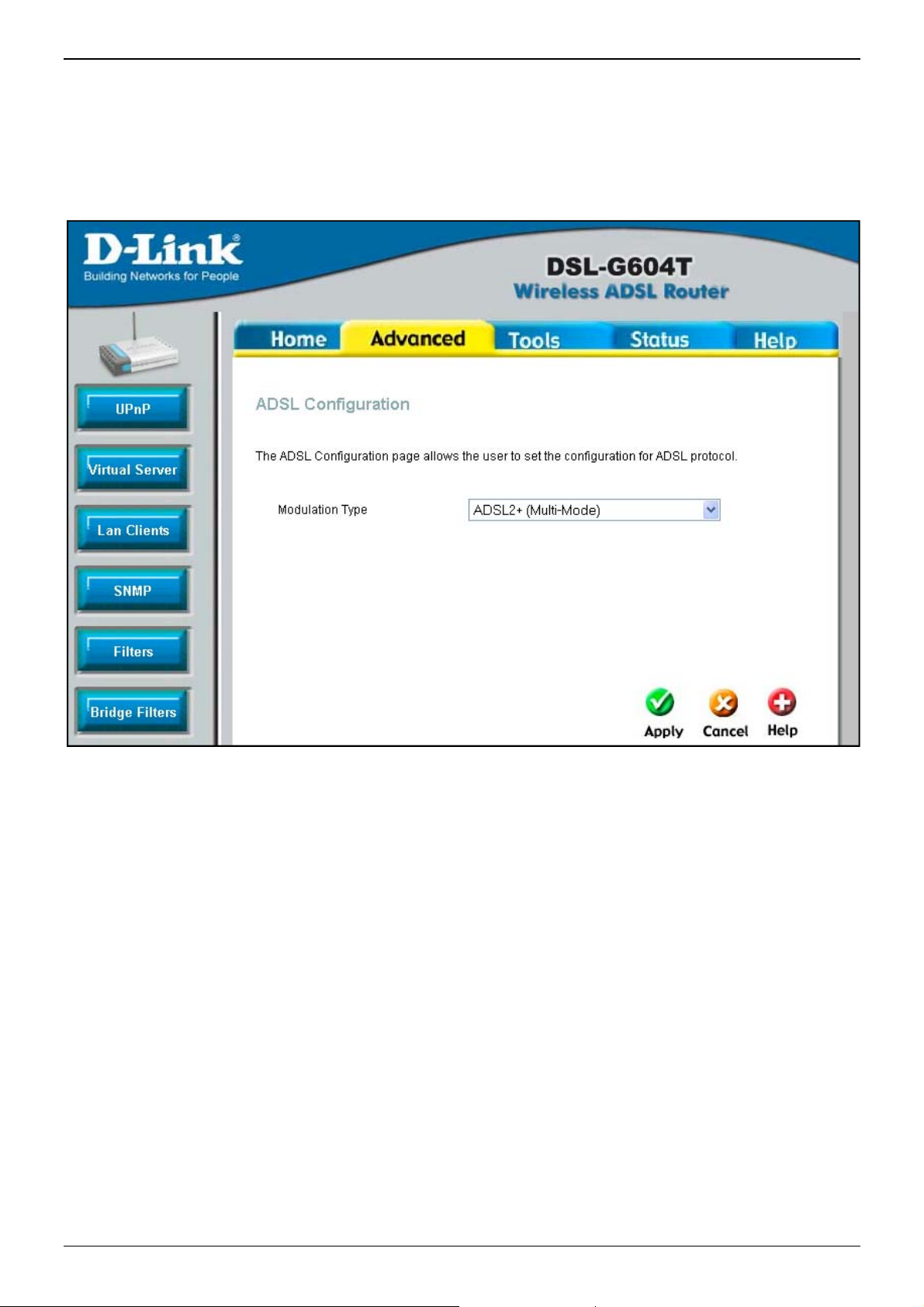
DSL-G604T Generation II ADSL2+ Wireless Modem Router
ADSL
The ADSL Configuration window allows the user to set the configuration for ADSL protocols. For most ADSL
accounts the default settings ADSL2+ (Multi-Mode) will work. This configuration works with all ADSL
implementations. If you have been given instructions to change the Modulation method used, select the desired
option from the Modulation Type drop-down menu and click the Apply button.
ADSL Configuration menu
Page 72 of 110 www.dlink.com.au
Page 73

DSL-G604T Generation II ADSL2+ Wireless Modem Router
ATM VCC
The ATM VC Setting window is used to configure the WAN connection. If you are using multiple PVCs, you can
change the configuration of any PVC in this window. To create new or additional PVCs, read the section on
Multiple PVCs.
This window can be used as an alternative to configure the same settings found on the WAN Settings window in
the Home directory.
ATM VC Settings menu
To configure an existing PVC configuration set, click the corresponding notepad icon in the right-hand column of
the ATM VCs List. The PVCs current settings appear above in the entry fields of the ATM VC Setting window.
Configure the appropriate settings and click the Apply button to put the new settings into effect.
Page 73 of 110 www.dlink.com.au
Page 74

Q
ointthe
afromuuseserTo
r
o
a
0
oS
y
N
P
s
p
e
w
n
)
o
c
N
a
m
e
r
w
t
A
u
T
a
e
s
f
s
u
t
l
w
u
i
d
r
m
c
A
C
t
G
n
o
e
f
e
N
m
,
n
S
a
o
w
N
G
t
b
r
e
p
e
r
t
h
o
r
t
h
N
w
r
I
M
s
h
y
h
e
A
o
,
a
S
w
m
Q
S or Qualit
erfaces (LA
lowest.
Th
e IGMP P
M
nagement
m the LAN
lticasting (
IGMP to
vice provid
of Service
and WAN
roxy/Sno
rotocol) pa
to the WA
treaming r
erform re
r. To enabl
DSL-G604
is used to
. The Rout
ping is di
kets to be
to reque
dio for exa
ote config
IGMP serv
Generation
ssign prior
r uses four
abled by
orwarded f
t multicast
mple is a
ration for
ice to the L
II ADSL2+
ty for quali
priority lev
efault. Thi
om the WA
group me
ulticast), m
lient device
N interface
Wireless M
ied traffic t
ls with “1”
s setting
to the LA
bership (I
ost users w
s, such as
select Ena
dem Route
hat passes
being the
ill not all
for the pu
MP Proxy).
ill not need
he Router.
led and clic
hrough the
ighest prio
w IGMP (
pose of IG
IGMP is u
to enable t
If unsure,
k the Appl
Router’s wi
ity while “4
nternet Gr
P snooping
ed to man
is. Some I
check with
button
red
” is
up
or
ge
Ps
the
set QoS fo
en the follo
op
fo
this combi
ch
osing the
B
ndwidth in
Note
r the route
ing windo
ation. The
PVC from
kbps from
QoS config
ports.
, first click
. Then sele
user may a
he pull-do
uto to 64
red in the Qo
QoS
he PortMa
ct the PVC
so enable I
n menu a
sing the dr
S menu appli
onfiguratio
pping QoS
o associate
MP Proxy/
d clicking
p-down me
s only to dat
menu
check box
with the co
nooping fo
the Enabl
u. Click A
traffic on th
in the midd
rresponding
any PVC a
d radio bu
ply to set t
Ethernet LA
le of the wi
port and c
the top of
tton and s
e configura
and the W
ndow. This
oose a prio
the windo
t a maxi
tion.
N (ADSL)
will
rity
by
um
Pa
ge 74 of 11
ww
.dlink.com
.au
Page 75

DSL-G604T Generation II ADSL2+ Wireless Modem Router
QoS Configuration window for Port Mapping QoS
The Router can also be configured to use the QoS infomation contained in the header of IP packets. This will
open the following window. To set IP QoS for the router, first click the IP QoS check box in the middle of the
window. Then select the PVC to associate with the corresponding action and choose a maximum bandwidth and
classification for this combination. Then select the classification type using the Classified by pull-down menu.
The choices are Disable, ToS, Application, and User Define. Each choice will open the corresponding windows,
shown following. The user may also enable IGMP Proxy/Snooping for each PVC at the top of the window by
choosing the PVC from the pull-down menu and clicking the Enabled radio button and set a maximum
Bandwidth in kbps from Auto to 64 using the drop-down menu. Click Apply to set the configuration.
Page 75 of 110 www.dlink.com.au
Page 76

DSL-G604T Generation II ADSL2+ Wireless Modem Router
QoS Configuration window IP QoS
If you select Disable in the Classified by drop-down menu, you can assign a maximum allowed bandwidth of
between 64 kbps and Auto to each of the PVCs configured on the router.
Page 76 of 110 www.dlink.com.au
Page 77

DSL-G604T Generation II ADSL2+ Wireless Modem Router
Additional options become available when you select either ToS, Application, or User Define from the Classified
by drop-down menu. Selecting ToS will display the following window.
QoS Configuration window IP QoS for ToS
From this window you can input a Weight in percentage and a priority range that will determine the mechanism
by which the four priority levels are “mapped”. For example, if you assign 100% and a range of 0 to 7 to
priority level 1, then the remaining priority levels (2 to 4) will only forward packets when priority level 1 is
empty (when there are no packets to forward). Some experimentation may be necessary to achieve the
optimum results with your particular ISP’s connection.
Page 77 of 110 www.dlink.com.au
Page 78

DSL-G604T Generation II ADSL2+ Wireless Modem Router
If you select Application from the Classified by drop-down menu, the following window appears.
QoS Configuration window IP QoS for Application
On this window, you can select the mechanism by which the four priority queues are emptied by assigning a
weight, in percentage terms, to each priority queue, and then assigning a packet type th at can be associated
with an application type. For example, if you assign a weight of 100% to Priority 1, with an application type of
Voice, then the other 3 priority queues (2 to 4) will not be allowed to forward packets until all of the Voi ce
packets have been sent from the priority 1 queue.
Page 78 of 110 www.dlink.com.au
Page 79

DSL-G604T Generation II ADSL2+ Wireless Modem Router
If you select User Define in the Classified by drop-down menu, the following window appears.
QoS Configuration window IP QoS for User Define
On this window, you can assign a weight, on a percentage basis, to each of the four priority queues. In
addition, you can specify the number of bytes from the beginning of a given packet’s IP header to set a pointer.
From this pointer, you can then specify a Value (in hexadecimal) and a Mask (in hexadecimal) for the router to
match when examining packets crossing the specified priority queue. It is recommended that you not enter a
QoS scheme of this type unless you fully understand Offsets, pointers, masks, and IP headers or you are
instructed to do so by your ISP.
Page 79 of 110 www.dlink.com.au
Page 80

DSL-G604T Generation II ADSL2+ Wireless Modem Router
Wireless Management
The Wireless Management menu includes separate menus for Access List, Associated Stations display and
Multiple SSID operation. Click the appropriate radio button to view the menu for any of these Wireless
Management menus.
Wireless Management - Access List menu
Access List
All computers are uniquely identified by their MAC (Media Access Control) address. The Access List menu is
used to allow or deny computers access to the Router’s Wireless interface based on their MAC address.
To enable the Access List, click to select the Enable Access List box and add MAC addresses to the list that
will be allowed or denied access.
To add a MAC address to the list, enter the MAC Address in the entry field provided using the format
00-00-00-00-00-00, select the radio button option to Allow or Deny access to the MAC address and click the
Add button. The MAC address will appear listed below. To remove a MAC Address from the list, click the Delete
radio button next to the MAC address.
All changes must be saved and the Router restarted for the Access List to be in effect.
The Associated Stations list can also be used to block access of any MAC address currently associated with
the Acess Point (see next section).
Page 80 of 110 www.dlink.com.au
Page 81

DSL-G604T Generation II ADSL2+ Wireless Modem Router
Associated Stations
Use the Associated Stations list to view wireless stations currently associated with the access point.
Wireless Management – Associated Stations display
The Associated Stations list displays the MAC address of stations currently associated wi th the Access Point.
Any station on the list can be banned and have the MAC address added to th e Access List of MAC addresses
denied access. To deny access to any associated stations click the radio button for the MAC address you want to
ban in the Ban Station column. Click Apply to add the banned station to the Access List (Denied) list. The
change must be saved and the Router restarted before the banned station appears in the list of Denied stations
on the Access List.
Page 81 of 110 www.dlink.com.au
Page 82

DSL-G604T Generation II ADSL2+ Wireless Modem Router
Multiple SSID
The access point in the Router supports use of multiple SSIDs. Up to 4 SSIDs may be used. Use the Multiple
SSID menu to enable, create and configure additional SSIDs for your wireless network.
Wireless Management – Multiple SSID menu
To use multiple SSID operation, click to select the Enable Multiple SSID box. Multiple SSID must be enabled
to create a new SSID configuration. After creating a secondary SSID, multiple SSID can be disabled by
deselecting the Enable Multiple SSID box.
To add security settings to an existing secondary SSID, click the Modify radio button for that SSID and
configure the security the same as configured in the general Wireless Settings menu (see page 31 for more
information). To remove a secondary SSID, click the Delete radio button for the SSID to be removed.
Page 82 of 110 www.dlink.com.au
Page 83

DSL-G604T Generation II ADSL2+ Wireless Modem Router
Wireless Performance
The Wireless Performance window is used to configure settings for the Access Point feature of this device.
Configuring these settings may increase the performance of your router but if you are not familiar with
networking devices and protocols, this section should be left at its default settings. Below is a list of the
functions associated with the Access Point feature of the router. Click Apply when you have completed your
changes.
Wireless Performance menu
See the table below for a description of Wireless Performance menu parameters.
Page 83 of 110 www.dlink.com.au
Page 84

DSL-G604T Generation II ADSL2+ Wireless Modem Router
Performance
Description
Parameters
Beacon Interval Beacons are emitted from the router in order to synchronize the wireless network. You
may set the Beacon Interval range between 20-100 microseconds per beacon sent. The
default is 100.
DTIM Period DTIM (Delivery Traffic Indication Message) Period is a countdown informing clients of the
next window for listening to broadcast and multicast messages. The default setting is 3.
Hidden SSID
Antenna transmit power Allows the user to adjust the transmit power of the router. A high transmit power allows
RTS Threshold The RTS (Request to Send) Threshold controls the size of data packets issued to a RTS
Frag Threshold The fragmentation threshold will determine if packets are to be fragmented. Packets over
Choose Enabled to STOP broadcasting the SSID across the network. When this is
enabled, the SSID willl be hidden from roaming devices. Choose Disabled if you want to
broadcast the SSID over the network.
a greater area range of accessibility to the router. When multiple overlapping access
points are present, it may be desirable to reduce transmition power.
packet. A lower level will send packets more frequently which may consume a great
amount of the available bandwidth. A high threshold will allow the router to recover from
interference or collisions which is more prevalent in a network with high traffic or high
electromagnetic interference. The default setting is 2347.
the 2346 byte limit will be fragmented before transmission. 2346 is the default setting.
b/g Mode The access point can be forced to operate in g mode or b mode to associate with
exclusively 802.11b or 802.11g devices. Additional options include b+ and g+, these are
enhanced higher speed operation modes for 802.11b and 802.11g devices that support it.
User Isolation When User Isolation is enabled, peer-to-peer communication is disabled. This prevents
unicasts from one wirless station to another in the same BSS.
QoS Support Select to enable wireless QoS priority (IEEE 802.11e) support.
Page 84 of 110 www.dlink.com.au
Page 85

DSL-G604T Generation II ADSL2+ Wireless Modem Router
Tools
Click the Tools tab to reveal the window buttons for various functions located in this directory. The
Administrator Settings window is the first item in the Tools directory. This window is used to change the
system password used to access the web manager, to save or load Router configuration settings and to restore
default settings. The functions in this and the other Tools windows are described below.
Administrator Settings window
Page 85 of 110 www.dlink.com.au
Page 86

A
h
oPaactma
e
0
m
e
e
n
f
u
b
s
i
r
d
y
r
n
r
A
v
T
d
h
e
p
t
e
v
a
m
c
a
W
t
e
e
e
w
p
r
p
M
s
a
o
n
n
f
t
y
t
>
o
r
S
A
h
v
w
.
b
u
w
e
c
d
A
w
o
i
n
w
n
dmin
Cli
ck the Adm
C
ange Sy
Cli
ck the Ad
pa
ssword leve
or
Modify us
pa
ssword, typ
M
dify admi
ssword to
ivate the n
nager inter
Yo
u may also
port used
th
in button in
stem Pa
in button
l being chan
r passwo
the New
passwor
be certain
ew passwo
ace.
se this me
y compute
DSL-G604
the Tools
sword
n the Tool
ged; click t
d option to
Password
. If you ar
ou have ty
d. The Sys
u to chang
s to access
Generation
irectory to
s directory
e Modify
change the
and Confir
changing
ed it corre
em User N
the TCP
the Interne
II ADSL2+
iew the th
to view th
dmin pass
user level
Passwo
the User’s
tly in the
me remain
ebPort use
.
Wireless M
Administr
the Admi
ord optio
assword. I
d to be cer
assword, t
odify user
“admin”,
d to access
dem Route
ator Settin
istrator
to change
you are c
ain you ha
pe the Ne
password
his cannot
the web ma
gs menu.
ettings m
dmistrator
anging the
e typed it
Passwor
Click the
be changed
nager. This
nu. Select
level pass
Administrat
orrectly in
and Conf
pply butto
using the
will not cha
the
ord
r’s
the
rm
to
eb
ge
Note
Pa
ge 86 of 11
The User le
dministrato
el password
r Settings m
allows limited
nu (top port
access to st
ion of Tools
tus displays
Admi n men
f the Router.
)
ww
.dlink.com
.au
Page 87

DSL-G604T Generation II ADSL2+ Wireless Modem Router
Remote Web Management and Remote Telnet Access
The Administrator Settings window is also used to enable remote Telnet management, remote SSH
management and remote web management access to the Router.
In each case, the procedure to enable remote management of the Router is the same. First, select the State
Enabled radio button for Remote Web Management, Remote Telnet Management, or Remote SSH
Management, and then type the IP Address and Netmask of the remote network or system used for
management. Finally, click the Apply button to activate remote management from the chosen IP address. Be
sure to save the new setting.
Remote Management (lower portion of Tools>Admin menu)
Page 87 of 110 www.dlink.com.au
Page 88

DSL-G604T Generation II ADSL2+ Wireless Modem Router
Time
The Router provides a number of options to maintain current date and time including SNTP.
Time menu
To configure system time on the Router, select the method used to maintain time. The options available include
SNTP, using your computer’s system clock (default) or set the time and date manually. If you opt to use SNTP,
you must enter the SNTP server URL or IP address. Click the Apply button to set the system time.
Page 88 of 110 www.dlink.com.au
Page 89

DSL-G604T Generation II ADSL2+ Wireless Modem Router
Remote Log
Use the Remote Log Settings window to set up logging to servers or computers that are located outside the
LAN or subnet of the Router.
Remote Log Settings window
Select the Log Level from the pull-down menu. The levels available are: Alert, Critical, Debug, Error, Info,
Notice, Panic and Warning. Type in the IP address of a receiver for the log message in the Add an IP Address
field and click on the Add button. Log message receivers that are added appear listed in the Select a logging
destination pull-down menu. These may be used at any time for other types of log messages. To remove a log
message receiver from the list, select it and click on the Remove button. Click the Apply button when you
have configured the log message receivers. Remember to save the settings to non-volatile memory.
Page 89 of 110 www.dlink.com.au
Page 90

DSL-G604T Generation II ADSL2+ Wireless Modem Router
System
Once you have configured the Router to your satisfaction, it is a good idea to back up the configuration file to
your computer. To save the current configuration settings to your computer, click the System button in the
Tools directory to display the System Settings window.
Save or Load Configuration File
Click the Save button to Save Settings to Local Hard Drive. You will be prompted to select a location on your
computer to put the file. The file type is .bin (encrypted binary) and may be named anything you wish.
To load a previously saved configuration file, click the Browse button and locate the file on your computer.
Click the Load button to Load Settings from Local Hard Drive. Confirm that you want to load the file when
prompted and the process is completed automatically. The Router will reboot and begin operating with the
configuration settings that have just been loaded.
System Settings window
Save Settings and Reboot System
To save the settings you have configured, click the Save and Reboot button under Save Settings and Reboot
the System.
Restore Factory Default Settings
To reset the Router to its factory default settings, click the Restore button. You will be prompted to confirm
your decision to reset the Router. The Router will reboot with the factory default settings including IP settings
(10.1.1.1) and Administrator password (admin).
Force the Wireless LAN to Restart
To restart the Wireless LAN component, click the Restart AP button. This will allow you to restart the Wireless
LAN component without kicking off any wired users that may be connected at the time.
Page 90 of 110 www.dlink.com.au
Page 91

F
i
nsetTo
0
r
m
s
a
e
e
T
p
t
o
i
m
n
o
b
y
i
w
T
n
i
e
r
o
o
g
a
o
m
e
t
r
y
t
w
o
h
e
a
v
t
f
rmwa
e
DSL-G604
Generation
II ADSL2+
Wireless M
dem Route
Note
e the Fir
Us
co
figuration
tings with t
Performing
up the Rout
ware Upg
ettings ma
he System
Firmware U
r’s configura
rade wind
y return to
Settings w
grade can s
ion settings
w to load
the factor
ndow descr
metimes cha
efore upgrad
the latest
default se
bed above.
ge the confi
ng the firmw
firmware f
ttings, so
uration settin
re.
r the devi
ake sure
gs. Be sure t
ce. Note t
ou save th
back-
at the de
configura
ice
ion
Firm
are Upgrad
upgrade fir
Cli
ck the Appl
Pa
ge 91 of 11
mware, typ
y button to
in the na
begin copyi
e and path
g the file.
of the file o
he file will l
menu
click on th
ad and res
Browse b
art the Rou
utton to se
er automat
ww
rch for the
ically.
.dlink.com
ile.
.au
Page 92

DSL-G604T Generation II ADSL2+ Wireless Modem Router
Miscellaneous
To perform a statndard Ping test for network connectivity, click the Misc. window button in the Tools directory
to view the Miscellaneous Configuration window.
Miscellaneous Configuration window
Other functions available in Miscellaneous Configuration menu are a Ping test and IGMP enable/disable.
Ping Test
The Ping test functions on the WAN and LAN interfaces. Type the IP address you want to check in the space
provided and click the Ping button. Read the Ping test result in the space immediately below.
Page 92 of 110 www.dlink.com.au
Page 93

DSL-G604T Generation II ADSL2+ Wireless Modem Router
Test
The Diagnostic Test window is used to test connectivity of the Router. A Ping test may be done through the
local or external interface to test connectivity to known IP addresses. The diagnostics feature executes a series
of test of your system software and hardware connections. Use this window when working with your ISP to
troubleshoot problems.
Diagnostic Test window
Page 93 of 110 www.dlink.com.au
Page 94

DSL-G604T Generation II ADSL2+ Wireless Modem Router
Status
Use the various read-only windows to view system information and monitor performance.
Device Info
Use the Device Information window to quickly view basic current information about the LAN and WAN
interfaces and device information including Firmware Version and MAC address.
Device Information window
Page 94 of 110 www.dlink.com.au
Page 95

DSL-G604T Generation II ADSL2+ Wireless Modem Router
DHCP Clients
This window will display all of the current DHCP clients that are connected to the router.
DHCP Clients window
Page 95 of 110 www.dlink.com.au
Page 96

DSL-G604T Generation II ADSL2+ Wireless Modem Router
Log
The system log displays chronological event log data. Use the navigation buttons to view or scroll log pages.
You may also save a simple text file containing the log to your computer. Click the Save Log button and follow
the prompts to save the file.
View Log window
Click Clear Log to delete the current log information.
Page 96 of 110 www.dlink.com.au
Page 97

DSL-G604T Generation II ADSL2+ Wireless Modem Router
Statistics
Use the Traffic Statistics window to monitor traffic on the Ethernet, Wireless or ADSL connection. Select the
interface for which you want to view packet statistics and the information will appear below.
Traffic Statistics window
Click Refresh to view traffic information.
Page 97 of 110 www.dlink.com.au
Page 98

DSL-G604T Generation II ADSL2+ Wireless Modem Router
ADSL Status
Use the ADSL Status window for troubleshooting the ADSL connection.
ADSL Status information
Page 98 of 110 www.dlink.com.au
Page 99

DSL-G604T Generation II ADSL2+ Wireless Modem Router
Help
Click the desired hyperlink to access help files.
Help window
Page 99 of 110 www.dlink.com.au
Page 100

DSL-G604T Generation II ADSL2+ Wireless Modem Router
Technical Specifications
General
A
ADSL Standards:
Protocols:
Data Transfer
Rate:
ADSL Standards
ANSI T1.413 Issue 2
ITU G.992.1 (G.dmt) Annex A
ITU G.992.2 (G.lite) Annex A
ITU G.994.1 (G.hs)
ITU G.992.5 Annex A
IEEE 802.1d Spanning Tree
TCP/UDP
ARP
RARP
ICMP
RFC1058 RIP v1
RFC1213 SNMP v1 & v2c
RFC1334 PAP
RFC1389 RIP v2
G.dmt full rate downstream: up to 8 Mbps / upstream: up to 1 Mbps
G.lite: ADSL downstream up to 1.5 Mbps / upstream up to 512 Kbps
G.dmt.bis full rate downstream: up to 12 Mbps / upstream: up to 1 Mbps
G.dmt.bisplus full rate downstream: up to 24 Mbps / upstream: up to 1 Mbps
ADSL2 Standards
• ITU G.992.3 (G.dmt.bis) Annex A
• ITU G.992.4 (G.lite.bis) Annex A
ADSL2+ Standards
ITU G.992.5 (G.dmt.bisplus) Annex A
RFC1483/2684 Multiprotocol Encapsulation over
ATM Adaptation Layer 5 (AAL5)
RFC1577 Classical IP over ATM
RFC1661 Point to Point Protocol
RFC1994 CHAP
RFC2131 DHCP Client / DHCP Server
RFC2364 PPP over ATM
RFC2516 PPP over Ethernet
ADSL interface: RJ-11 connector for connection to 24/26 AWG twisted pair
Media Interface:
telephone line
LAN interface: RJ-45 port for 10/100BASE-T Ethernet connection
Page 100 of 110 www.dlink.com.au
 Loading...