

D-Link DSL-6540U User Manual

DSL-6540U
User Manual
VER: 1.0

i
Contents
1 Introduction .............................................................................................. 2
1.1 Application............................................................................................. 2
1.2 Features ................................................................................................2
1.3 Standards Compatibility and Compliance.............................................. 2
1.4 Safety Cautions ..................................................................................... 2
1.5 LED Status Description.......................................................................... 2
1.5.1 LED Status..................................................................................2
1.5.2 Rear Panel..................................................................................2
2 Hardware Installation ............................................................................... 2
2.1 Connecting the DSL Router................................................................... 2
2.2 Factory Reset Button.............................................................................2
3 Introduction .............................................................................................. 2
3.1 About DSL router...................................................................................2
3.2 Setup ..................................................................................................... 2
3.2.1 Setting Up WAN and LAN Connections ..................................... 2
3.2.2 PC Network Configuration .......................................................... 2
4 Web-Based Management ........................................................................ 2
4.1 Logging In to the Modem.......................................................................2
4.1.1 First-Time Login..........................................................................2
4.2 DSL Router Device Information............................................................. 2
4.2.1 Summary of Device Information ................................................. 2
4.2.2 WAN Interface Information .........................................................2
4.2.3 Statistics...................................................................................... 2
4.2.4 Route Table Information.............................................................. 2
4.2.5 ARP Table Information................................................................ 2
4.2.6 DHCP IP Lease Information .......................................................2
4.3 Advanced Setup .................................................................................... 2
4.3.1 Layer2 Interface.......................................................................... 2
4.3.2 WAN Configuration ..................................................................... 2
4.3.3 LAN Configuration ......................................................................2

ii
4.3.4 NAT ............................................................................................. 2
4.3.5 Security....................................................................................... 2
4.3.6 Parental Control.......................................................................... 2
4.3.7 Quality of Service........................................................................ 2
4.3.8 Routing .......................................................................................2
4.3.9 DSL............................................................................................. 2
4.3.10 UPNP.......................................................................................... 2
4.3.11 DNS Proxy .................................................................................. 2
4.3.12 Print Server................................................................................. 2
4.3.13 Interface Grouping ...................................................................... 2
4.3.14 IPsec........................................................................................... 2
4.3.15 Certificate.................................................................................... 2
4.4 Diagnostics............................................................................................ 2
4.4.1 Diagnostics - Fault Management................................................ 2
4.5 Management.......................................................................................... 2
4.5.1 Settings....................................................................................... 2
4.5.2 System Log................................................................................. 2
4.5.3 TR-69 Client Management ......................................................... 2
4.5.4 Internet Time............................................................................... 2
4.5.5 Access Control............................................................................ 2
4.5.6 Update Software ......................................................................... 2
4.5.7 Reboot ........................................................................................ 2

1
1 Introduction
The VDSL DSL-6540U is a high-speed VDSL2 router, uplink rate up to 40 Mbps
and downlink rate up to 80 Mbps. It provides sufficient bandwidth for high
performance connection to the Internet, online gaming, video on demand (VOD),
video conferencing, and high definition television (HDTV). It has Web-based
graphic user interface (GUI), in which you can easily modify the settings and
connect to your ISP. It also provides flow statistics, connection status, and other
detailed information. The VDSL DSL-6540U is easily upgraded and provides
terminal users and ISP with the guarantee of future.
The VDSL DSL-6540U provides one RJ11 telephone interface, one RJ45 Ethernet
WAN interface, four RJ45 Ethernet LAN interfaces. The telephone interface is used
for connecting to the Internet provided by the telecom carrier. The Ethernet is used
for connecting to computers, through which you can access the Internet.
Computers that are connected with the router through the Ethernet can establish a
small local network area (LAN). Those computers can communicate with each
other, sharing resources and files. The VDSL DSL-6540U is an ideal broadband
CPE solution for both home users who wish to share high-speed Internet access
and small offices that wish to do business on the Internet.
1.1 Application
VOD and video-conferencing
Network online gaming
IP over television (IPTV )and HDTV
High Internet access sharing
High rate broadband sharing
Small enterprises application
Home networking application
1.2 Features

2
User-friendly GUI for web configuration
Support IPSec for virtual private network (VPN)
Several pre-configured popular games. Just enable the game and the port
settings are automatically configured.
Configurable as a DHCP server on your network
Compatible with all standard Internet applications
Industry standard and interoperable DSL interface
Support virtual server, IP filter, DMZ host, and much more
Simple web-based status page displays a snapshot of system configuration,
and links to the configuration pages
Downloadable flash software updates
Support for up to 16 permanent virtual circuits (PVC)
Support for up to 8 PPPoE sessions
Support SNMP v2, RIP v1 & RIP v2, NAT
1.3 Standards Compatibility and Compliance
Support application level gateway (ALG)
ITU G.992.1 (G.dmt)
ITU G.992.2 (G.lite)
ITU G.994.1 (G.hs)
ITU G.992.3 (ADSL2)
ITU G.992.5 (ADSL2+)
ITU G.993.1 (VDSL)
ITU G993.2 (VDSL2)
ANSI T1.413 Issue 2
IEEE 802.3
IEEE 802.3u
1.4 Safety Cautions
Follow the following announcements to protect the device from risks and damage
caused by fire and electric power:
Use volume labels to mark the type of power.
Use the power adapter that is packed within the device package.
3
Pay attention to the power load of the outlet or prolonged lines. An
overburden power outlet or damaged lines and plugs may cause electric
shock or fire accident. Check the power cords regularly. If you find any
damage, replace it at once.
Proper space left for heat dissipation is necessary to avoid any damage
caused by overheating to the device. The holes on the device are designed
for heat dissipation to ensure that the device works normally. Do not cover
these heat dissipation holes.
Do not put this device close to a place where a heat source exits or high
temperature occurs. Avoid the device from direct sunshine.
Do not put this device close to a place where is over damp or watery. Do not
spill any fluid on this device.
Do not connect this device to any PC or electronic product, unless our
customer engineer or your broadband provider instructs you to do this,
because any wrong connection may cause any power or fire risk.
Do not place this device on an unstable surface or support.
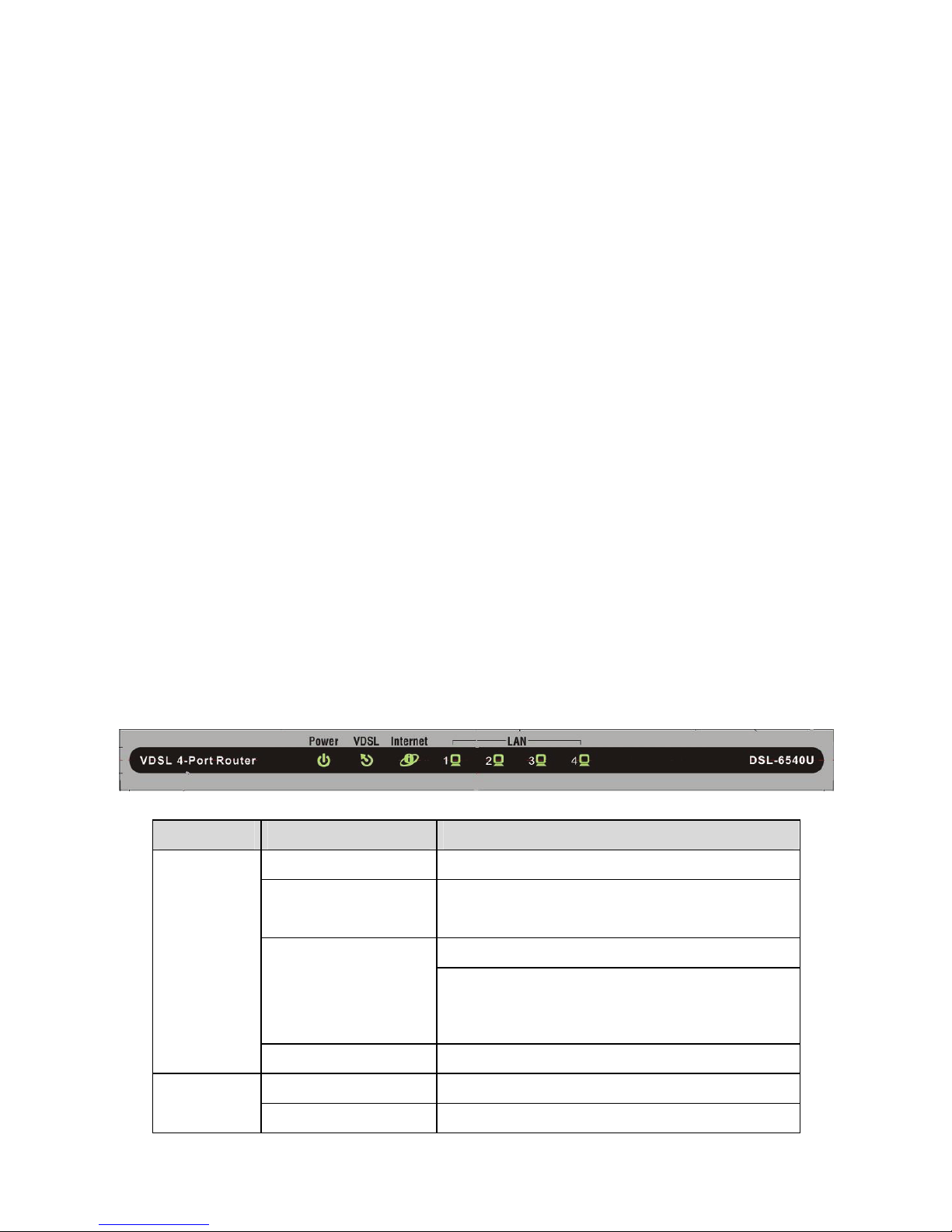
1.5 LED Status Description
1.5.1 LED Status
Indicator Status Description
Off The power is off.
Green
The power is on and the device operates
normally.
The power is self-testing.
Red
The self-testing of the power fails if the
LED is always red.
Power
Blink Red Upgrading software.
Off No signal is detected. VDSL
Blink Green The VDSL line is transferring.
4
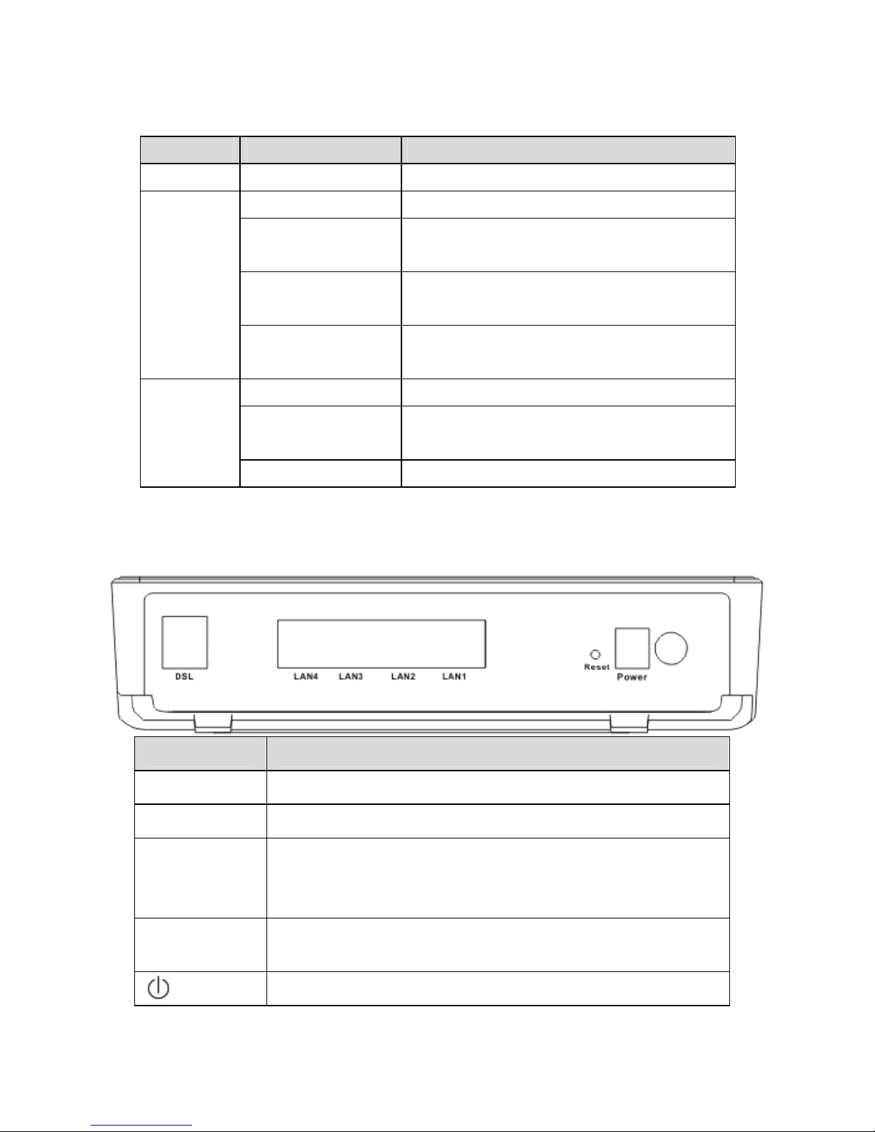
Indicator Status Description
Green The DSL line connection is established.
Off No internet connection.
Blink Red
The DSL line tries to activate or fails to
activate.
Blink Green
Data is being transmitted through the
WAN interface.
Internet
Green
The connection is established. The users
can access the Internet.
Off No Ethernet signal is detected.
Blink Green
The user data is passing through
Ethernet port.
LAN1/2/3/4
Green Ethernet interface is ready to work
1.5.2 Rear Panel
Interface Description
VDSL
VDSL connector, for connecting to VDSL telephone line.
LAN1/2/3/4
LAN interface, for connecting to a computer or switch.
Reset
Keep power on, put a thin needle in-to the hole to press
the button for about 1 second, then the device restores to
the factory default configuration.
Power
Power supplied port, for connecting the power adapter.
The power adapter output is: 12 V DC, 1A.
Power switch.
5
2 Hardware Installation
The Router can be placed on a shelf or desktop, ideally you should be able to see
the LED indicators in the front, as you may need to view them for troubleshooting.
Place the DSL Router in a location where it can be connected to the various
devices as well as to a power source. The DSL Router should not be placed where
it is exposed to moisture or excessive heat. Ensure the cables and power cord are
placed safely to avoid tripping hazard. As with any electrical appliance, observe
common sense safety procedures.
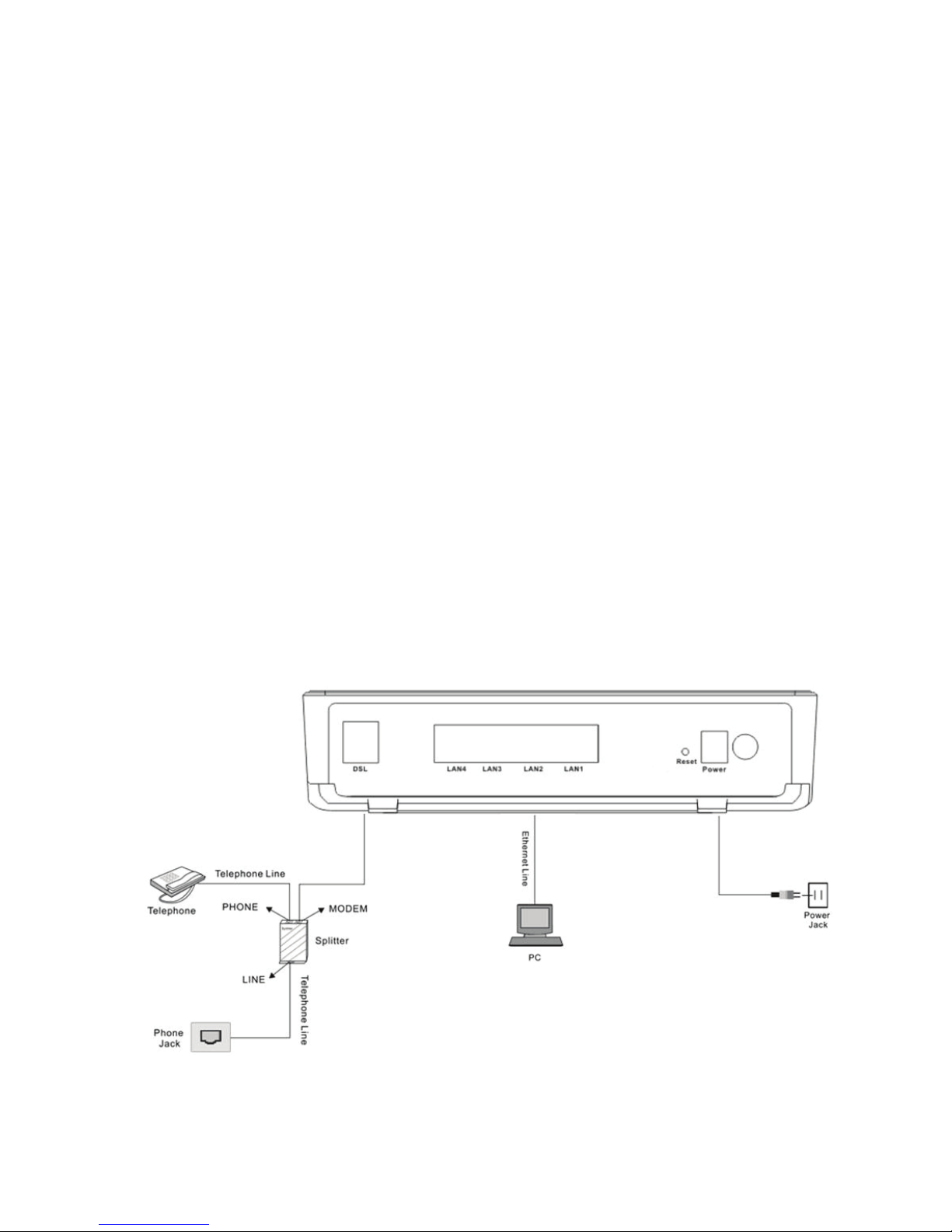
2.1 Connecting the DSL Router
Step 1 See the following figure. Connect the DSL port of the Router with a telephone
cable.
Step 2 Connect the LAN port of the DSL Router to the network card of the PC via an
Ethernet cable.
Step 3 Plug one end of the power adapter to the wall outlet and connect the other
end to the Power port of the DSL Router.
The followig figure displays the connection of the DSL Router, PC, and telephones.
2.2 Factory Reset Button

6
The Router may be reset to the original factory default settings by depressing the
reset button for a few seconds while the device is powered on. Use a ballpoint or
paperclip to gently push down the reset button. Remember that this wipes out any
settings stored in the flash memory, including user account information and LAN IP
settings. The device settings are restored to the following factory defaults: the IP
address is 192.168.1.1, subnet mask is 255.255.255.0, user name for
management is admin, and password is admin.
3 Introduction
3.1 About DSL router
DSL router is a scalable suite of software infrastructure and technologies that
original equipment manufacturers (OEMs) require in order to bring residential
gateways to market.
DSL router leverages a wide range of compelling broadband-based applications
and services and includes an operating system, drivers, and remote management
capabilities. DSL router delivers a set of highly integrated solutions, required for
homes and small companies, such as:
Optimized Linux 2.6 Operating System
IP routing and bridging
Asynchronous transfer mode (ATM/PTM) and digital subscriber line (DSL)
support
Point-to-point protocol (PPP)
Network/port address translation (NAT/PAT)
Quality of service (QoS)
Virtual private network (VPN): IPSec
Secure socket layer virtual private network (SSL VPN)
Universal plug-and-play
File server for network attached storage (NAS) devices
Web filtering
Management and control
– Web-based management (WBM)
– Simple network management protocol (SNMP)
7
– Command line interface (CLI)
– TR-069 WAN management protocol
– TR-064-LAN-side DSL CPE configuration
Remote update
System statistics and monitoring
DSL router is targeted at the following platforms: DSL modem and bridge.
3.2 Setup
Connecting your computer or home network to the DSL router is a simple
procedure, varying slightly depending on the operating system. This chapter
guides you to seamlessly integrate DSL router with your computer or home
network. The Windows default network settings dictate that in most cases the setup
procedure described as follows is unnecessary. For example, the default DHCP
setting in Windows 2000 is 'client', requiring no further modification. However, it is
advised to follow the setup procedure described as follows to verify that all
communication parameters are valid and that the physical cable connections are
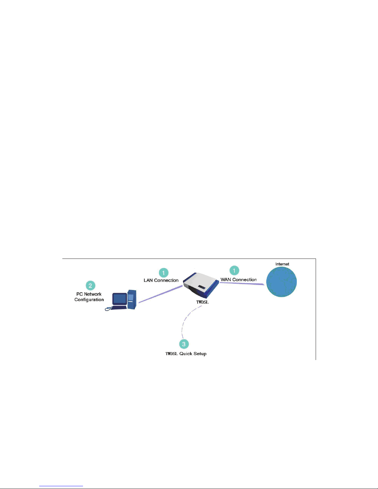
correct. The setup procedure consists of three consecutive configuration stages:
Figure 1 Hardware configuration
(1) Setting up WAN and LAN connections
(2) PC network configuration
(3) DSL router quick setup, via Web-based management
3.2.1 Setting Up WAN and LAN Connections
WAN Connection

8
Your can connect DSL interface of the router to the wall socket by using a
telephone cable. If it has an Ethernet socket for the wide area network (WAN),
connect it to the external modem you have, or to the Ethernet socket you might
have, by using an Ethernet cable.
LAN Connection
The connection is Ethernet, with most platforms featuring four such ports. Use an
Ethernet cable to connect an Ethernet port of your DSL router and the network card
of your computer.
3.2.2 PC Network Configuration
Each network interface on the PC should either be configured with a statically
defined IP address and DNS address, or be instructed to automatically obtain an IP
address using the network DHCP server. DSL router provides a DHCP server on
its LAN and it is recommended to configure your LAN to automatically obtain its IP
address and DNS server IP address.
The configuration principle is identical but should be carried out differently on each
operating system.
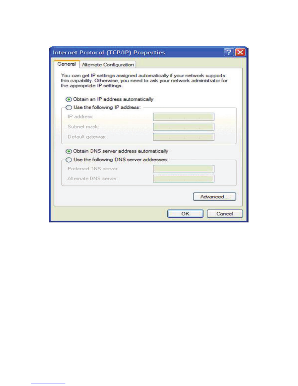
The following displays the TCP/IP Properties dialog box as it appears on Windows
XP.
9
Figure 2 IP and DNS configuration
TCP/IP configuration instructions for Windows XP are as follows.
Step 1 Choose Start > Control Panel > Access Network Connections from
the desktop.
Step 2 Right-click the Ethernet connection icon and choose Properties.
Step 3 On the General tab, select the Internet Protocol (TCP/IP) component
and click Properties.
Step 4 The Internet Protocol (TCP/IP) Properties window appears.
Step 5 Select the Obtain an IP address automatically radio button.
Step 6 Select the Obtain DNS server address automatically radio button.
Step 7 Click OK to save the settings.
10
4 Web-Based Management
Note:
This project is hardware project, the Web interface of software is for reference
only.
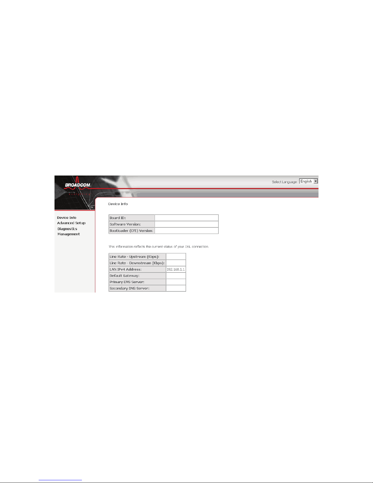
This chapter describes how to use Web-based management of the DSL router,
which allows you to configure and control all of DSL router features and system
parameters in a user-friendly GUI.
Figure 3 Web-based management - home page
4.1 Logging In to the Modem
The following description is a detail “How-To” user guide and is prepared for first
time users.
4.1.1 First-Time Login
When you log in to the DSL Router for the first time, the login wizard appears.
Step 1 Open a Web browser on your computer.
Step 2 Enter http://192.168.0.1 (default IP address of the DSL router) in the
address bar. The login page appears.
Step 3 Enter a user name and the password. The default username and
password of the super user are admin and (blank). The username and
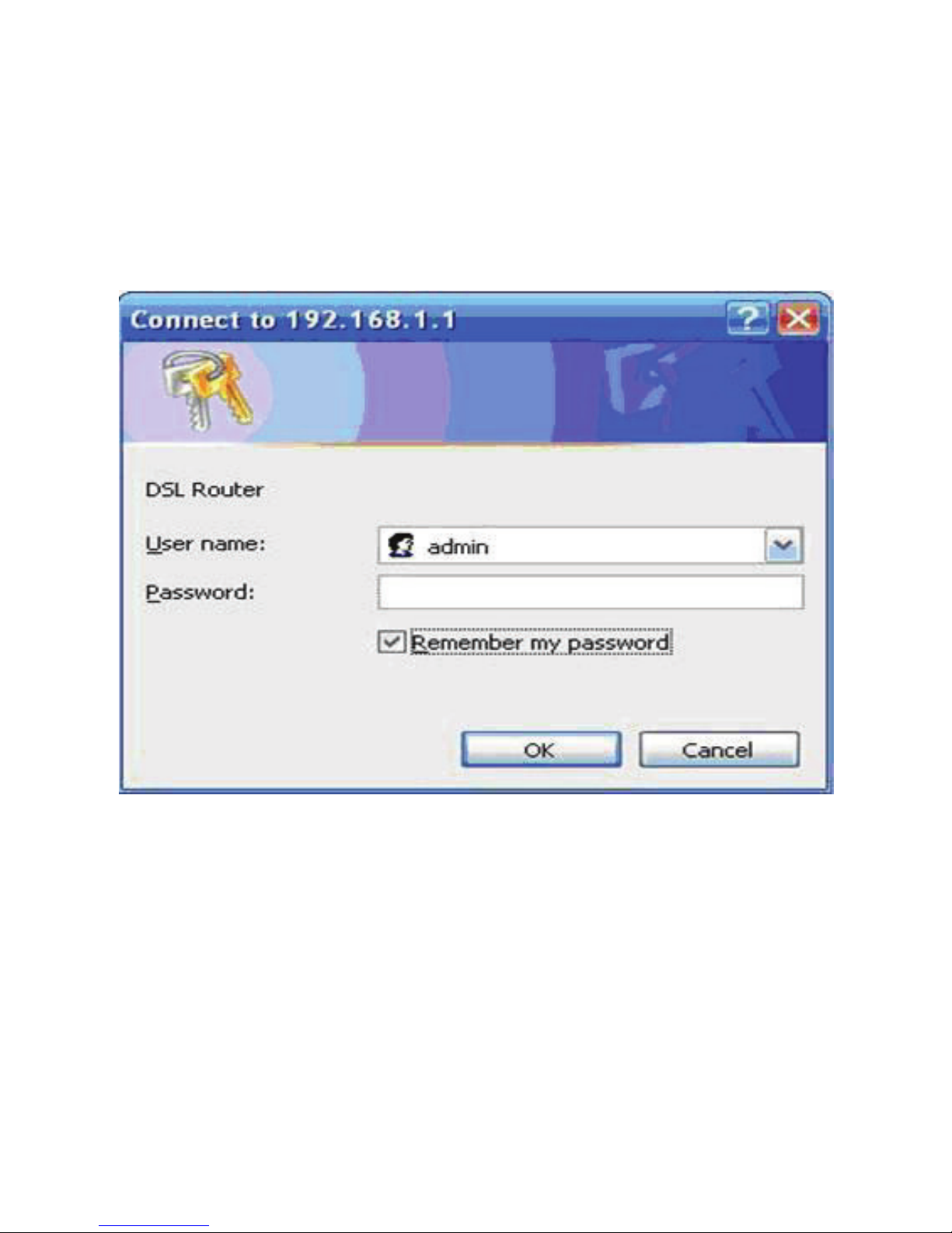
11
password of the common user are user and user. You need not enter
the username and password again if you select the option Remember
my password. It is recommended to change these default values after
logging in to the DSL router for the first time.
Step 4 Click OK to log in or click Cancel to exit the login page.
Figure 4 WBM login authentication
After logging in to the DSL router as a super user, you can query, configure, and
modify all configurations, and diagnose the system.
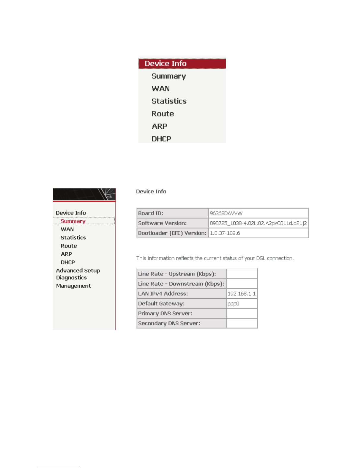
4.2 DSL Router Device Information
Choose Device Info, the following page appears.
12
Figure 5 Device Info menu
4.2.1 Summary of Device Information
Choose Device Info > Summary, the following page appears.
LAN IPv4 Address: the management IPv4 address.
Default Gateway: In the bridging mode there is no gateway. In other modes,
it is the address of the uplink equipment, for example, PPPoE/PPPoA.
DNS Server address: In the PPPoE/PPPoA mode, it is obtained from the
uplink equipment. In the bridging mode, there is no DNS Server address and
you can manually enter the information.
4.2.2 WAN Interface Information
Choose Device Info > WAN and the following page appears.

13
Description: Descripte this interface with protocol and PVC.
Type: The connection type of WAN, such as PPPoE, PPPoA.
4.2.3 Statistics
This page contains the following four parts:
Statistics of LAN
Statistics of WAN Service
Statistics of ATM
Statistics of xDSL
4.2.3.1 Statistics of LAN
Choose Device Info > Statistics > LAN and the following page appears. You can
query information of packets recevied at the Ethernet. Click Reset Statistics to
restore the values to zero and recount them.
14
Figure 6 Statistics of LAN
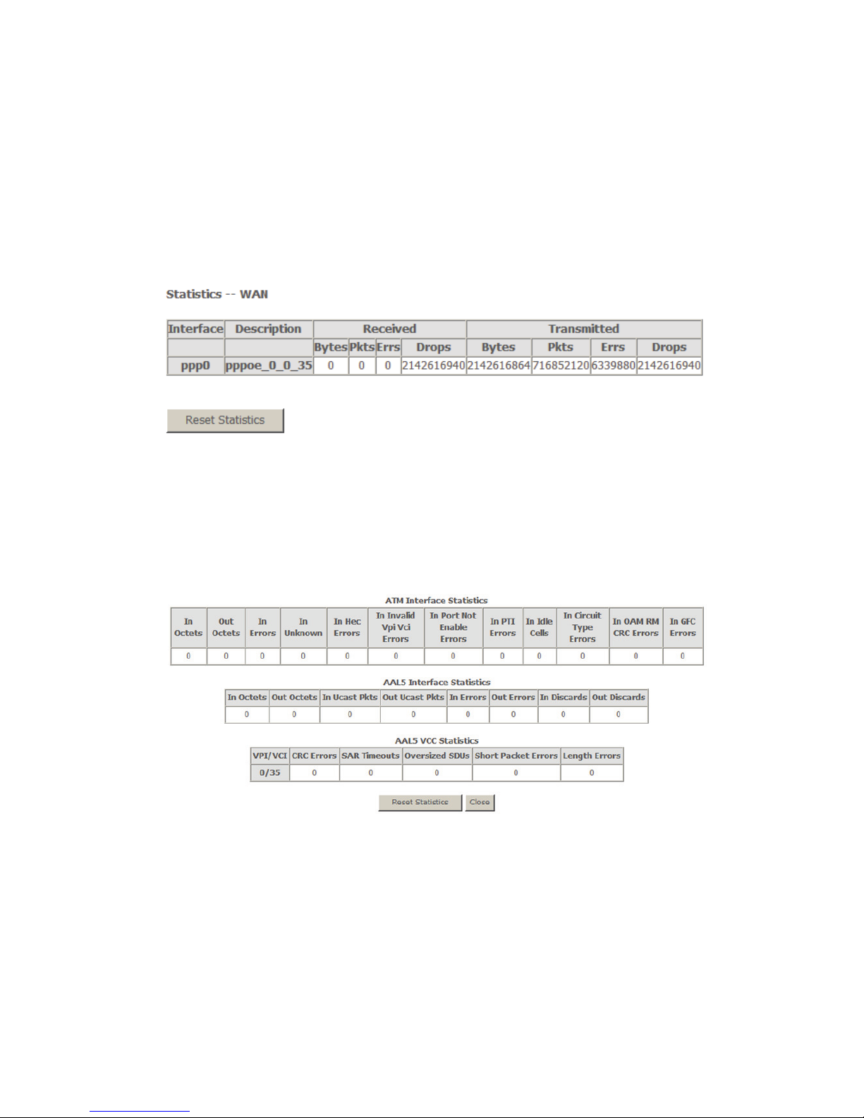
4.2.3.2 Statistics of WAN
Choose Device Info > Statistics > WAN Service and the following page appears.
You can query information of packets recevied by the WAN interfaces. Click Reset
Statistics to restore the values to zero and recount them.
Figure 7 Statistics of WAN
4.2.3.3 Statistics of ATM
Choose Device Info > Statistics > ATM and the following page appears. You can
query information of packets recevied by the ATM interfaces. Click Reset
Statistics to restore the values to zero and recount them.
Figure 8 Statistics of ATM
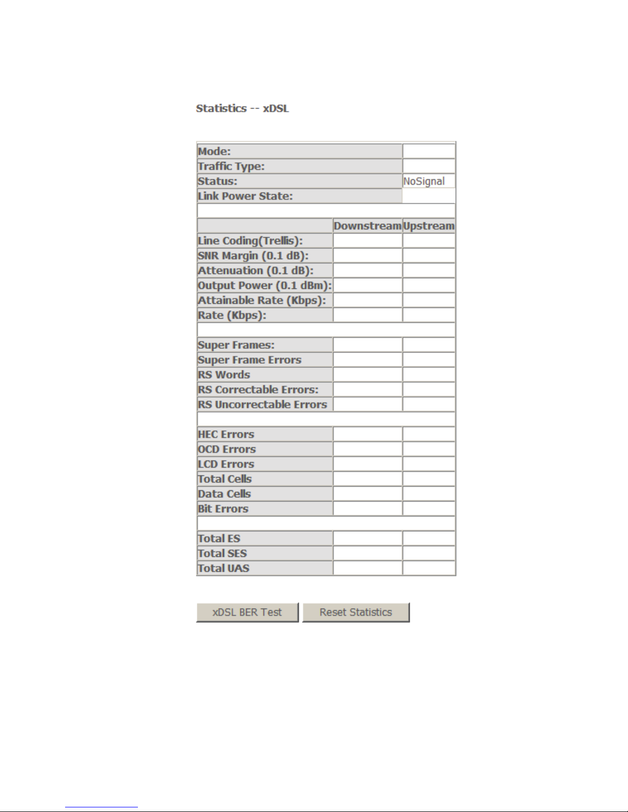
4.2.3.4 Statistics of xDSL
Choose Device Info > Statistics > xDSL and the following page appears.
If the DSL line is activated, the following window appears.
15
Traffic Type: ATM, or PTM.
Status: Link Down, NoSignal, Training
Link Power State: L0, L1, L2
Line Coding: Trallis on, etc.
Rate (Kbps): Upstream Line Rate/Downstream Line Rate.

16
Click Reset Statistics at the bottom to restore the values to zero and recount
them.
Click xDSL BER Test to test xDSL Bit Error Rate.
4.2.3.5 xDSL BER Test
Click xDSL BER Test to perform a bit error rate (BER) test on the DSL line. The
test page is as follows:
Figure 9 ADSL BER test
The Tested Time (sec) can be 1, 5, 10, 20, 60, 120, 180, 240, 300, or 360.
Note: If the BER reaches e-5, you cannot access the
Internet.
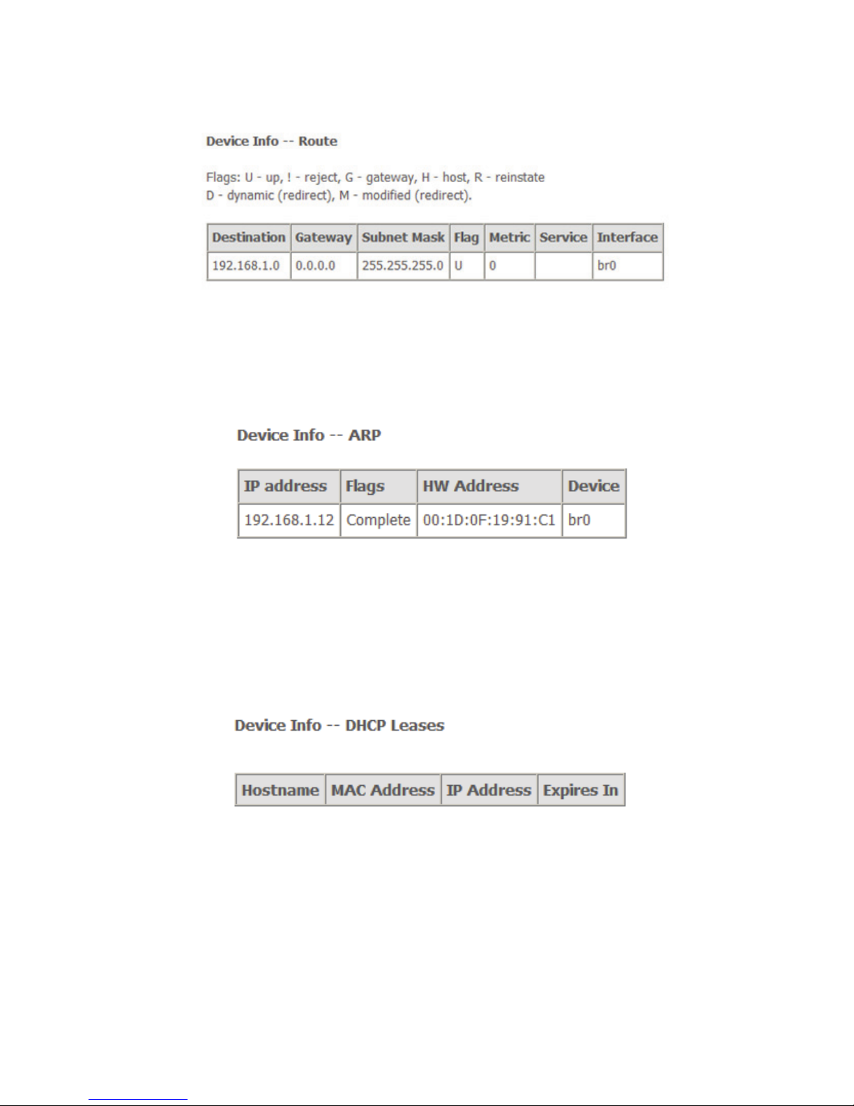
4.2.4 Route Table Information
Choose Device Info > Route and the following page appears.
17
Figure 10 Route table
4.2.5 ARP Table Information
Choose Device Info > ARP and the following page appears. You can query the
MAC and IP address information of the equipment attached to the modem.
Figure 11 ARP table
4.2.6 DHCP IP Lease Information
Choose Device Info > DHCP and the following page appears. You can query the
IP address assignment for MAC address at the LAN side of the DSL router and
obtain the IP Address from the DHCP server through Ethernet in the DSL router.
Figure 12 DHCP leases list
Expires In: Time that the device leases the IP Address for the MAC
Address.
4.3 Advanced Setup
18
4.3.1 Layer2 Interface
Choose Advanced Setup > Layer2 Interface and three items appear.
ATM Interface
PTM Interface
ETH Interface
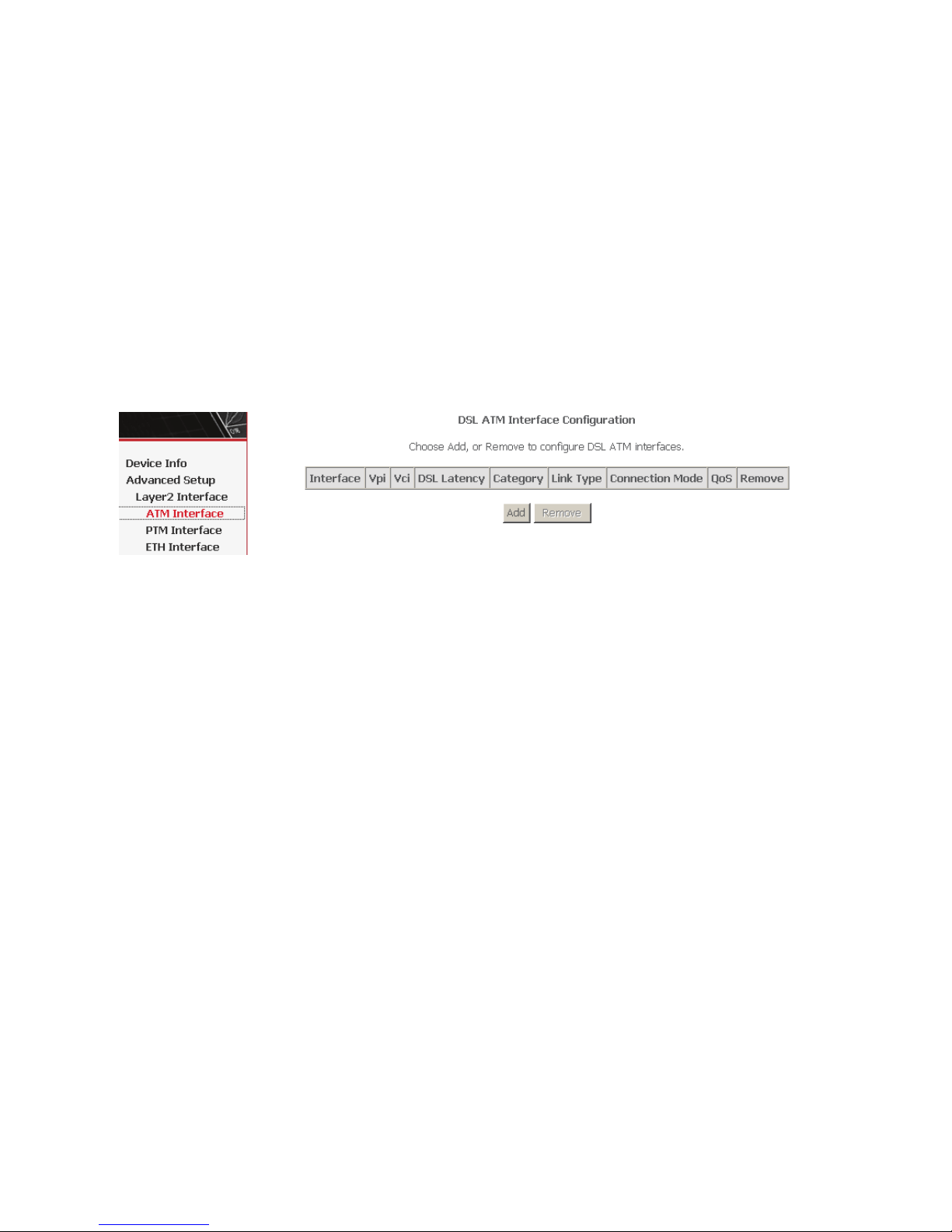
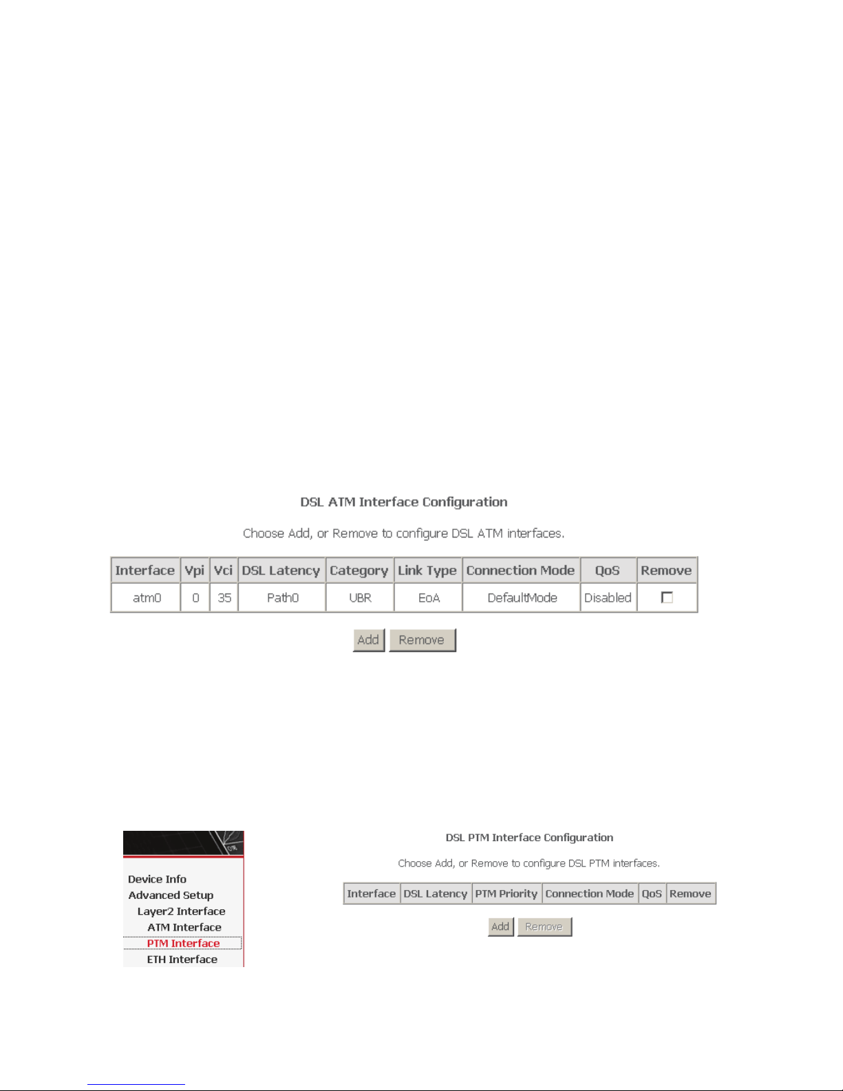
4.3.1.1 ATM Interface
Choose Advanced Setup > Layer2 Interface > ATM Interface . In this page, you
can add or remove to configure DSL ATM Interfaces.
Click Add to add ATM Interface and the following page appears.
19
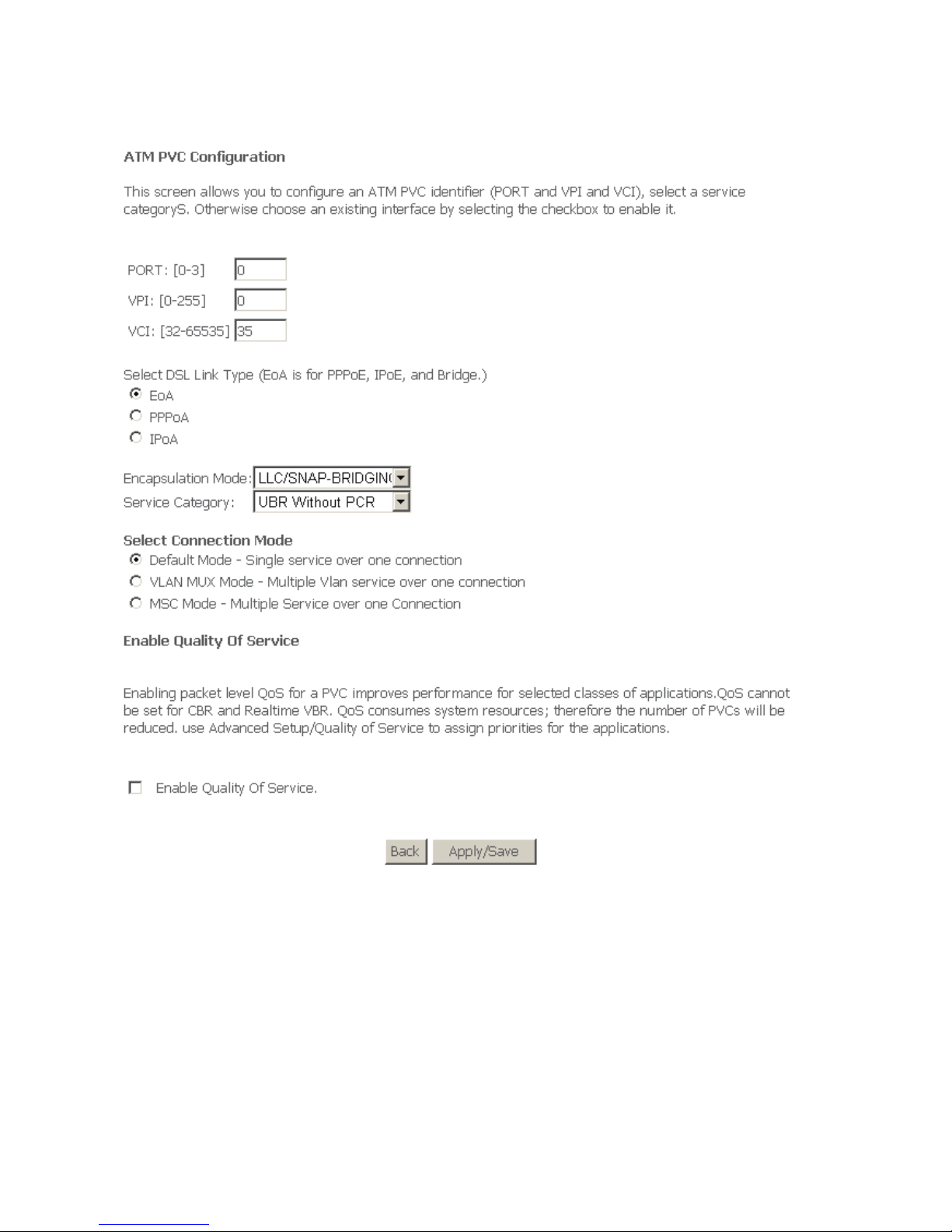
In this page, you can enter this PVC (VPI and VCI) value, and select DSL link type
(EoA is for PPPoE, IPoE, and Bridge.), encapsulation mode, service category,
connection Mode.
VPI (Virtual Path Identifier): The virtual path between two points in an ATM
network, and its valid value is from 0 to 255.
VCI (Virtual Channel Identifier): The virtual channel between two points in
an ATM network, ranging from 32 to 65535 (1 to 31 are reserved for known
protocols).
DSL Link Type: EoA (it is for PPPoE, IPoE, and Bridge), PPPoA, or IPoA
20
Encapsulation Mode: LLC/SNAP-BRIDGING, or VC/MUX
Service Category: UBR Without PCR, UBR With PCR, CBR, Non Realtime
VBR, Realtime VBR.
Connection Mode: Default mode, VLAN MUX mode, or MSC mode
Enable Quality Of Service: enable/disable.
In actual applications, you can modify them depending on your requirement.
You can also select the Enable Quality Of Service check box in to enable the
packet level QoS for a PVC. This improves performance for selected classes of
applications.
Note:
QoS cannot be set for CBR and Realtime VBR.
Click Apply/Save to save the configuration, and return the following page:
If you want to remove this Interface, please select the Remove check box and click
Remove.
4.3.1.2 PTM Interface
Choose Advanced Setup > Layer2 Interface > PTM Interface, and the following
page appears. In this page, you can add or remove to configure PTM WAN
Interfaces.
Click Add to add PTM Interface and the following page appears.
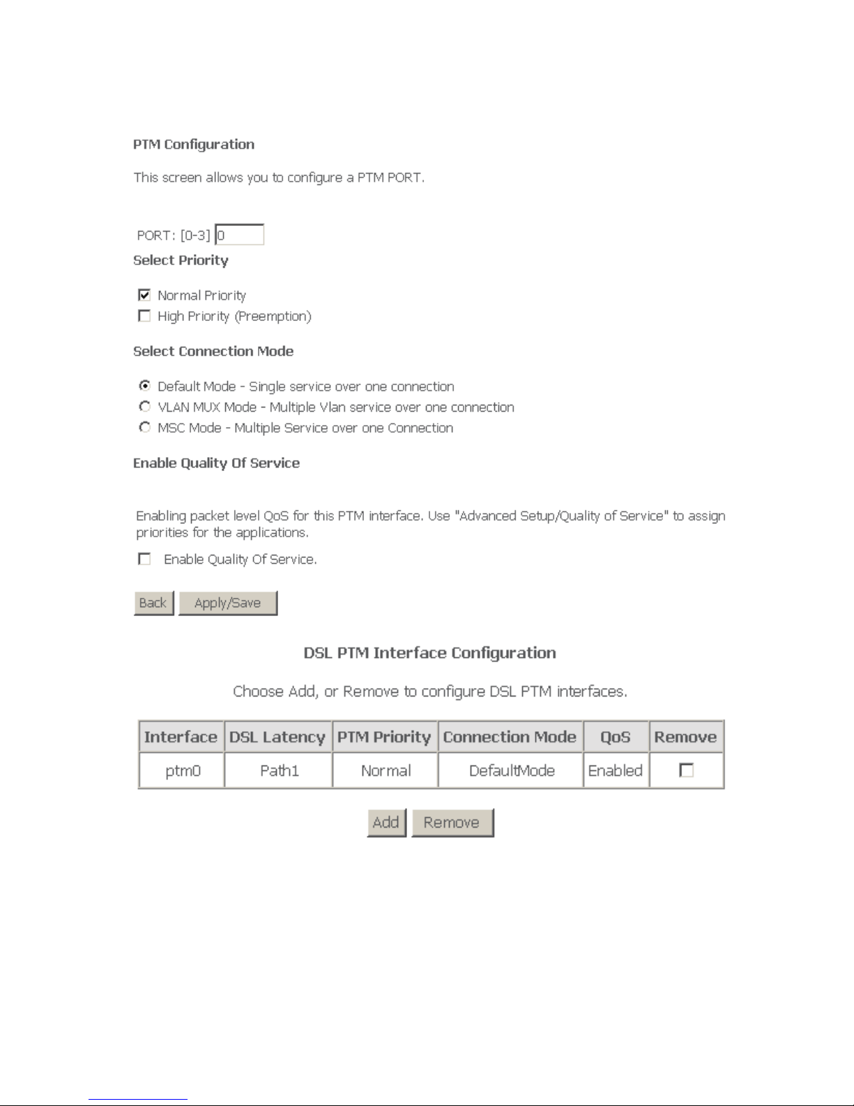
21
After proper configuration, click Apply/Save.
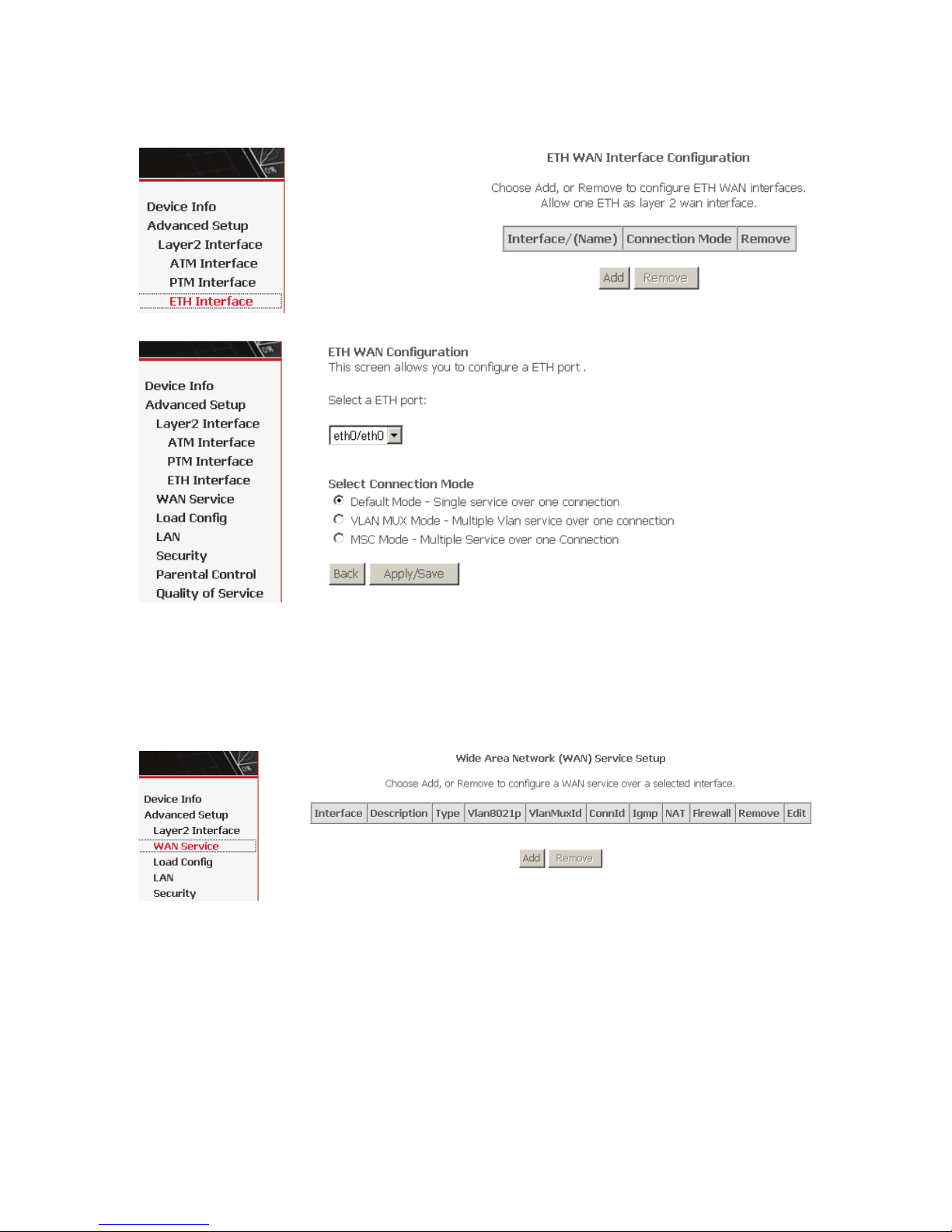
4.3.1.3 ETH Interface
Choose Advanced Setup > Layer2 Interface > ETH Interface, and the following
page appears. In this page, you can add or remove to configure ETH WAN
Interfaces.
22
Click Add and the following page appears.
In this page, you can select a ETH port, such as eth0/ENET4, and select
connection mode. Click Apply/Save to save configuration.
4.3.2 WAN Configuration
Choose Advanced Setup > WAN Service, and the following page appears.
Figure 13 WAN configuration
Click Add to configure PPPoE, PPPoA, Mer (IPoE), Bridge, IPoA WAN
configuration.
Note: ETH and PTM/ATM sevice can not be coexist.
23
4.3.2.1 Adding a PPPoE WAN Configuration
In the WAN Service Setup page, click Add to add WAN configuration. This section
describes the procedure for adding pppoe_0_0_32 (PPPoE mode).
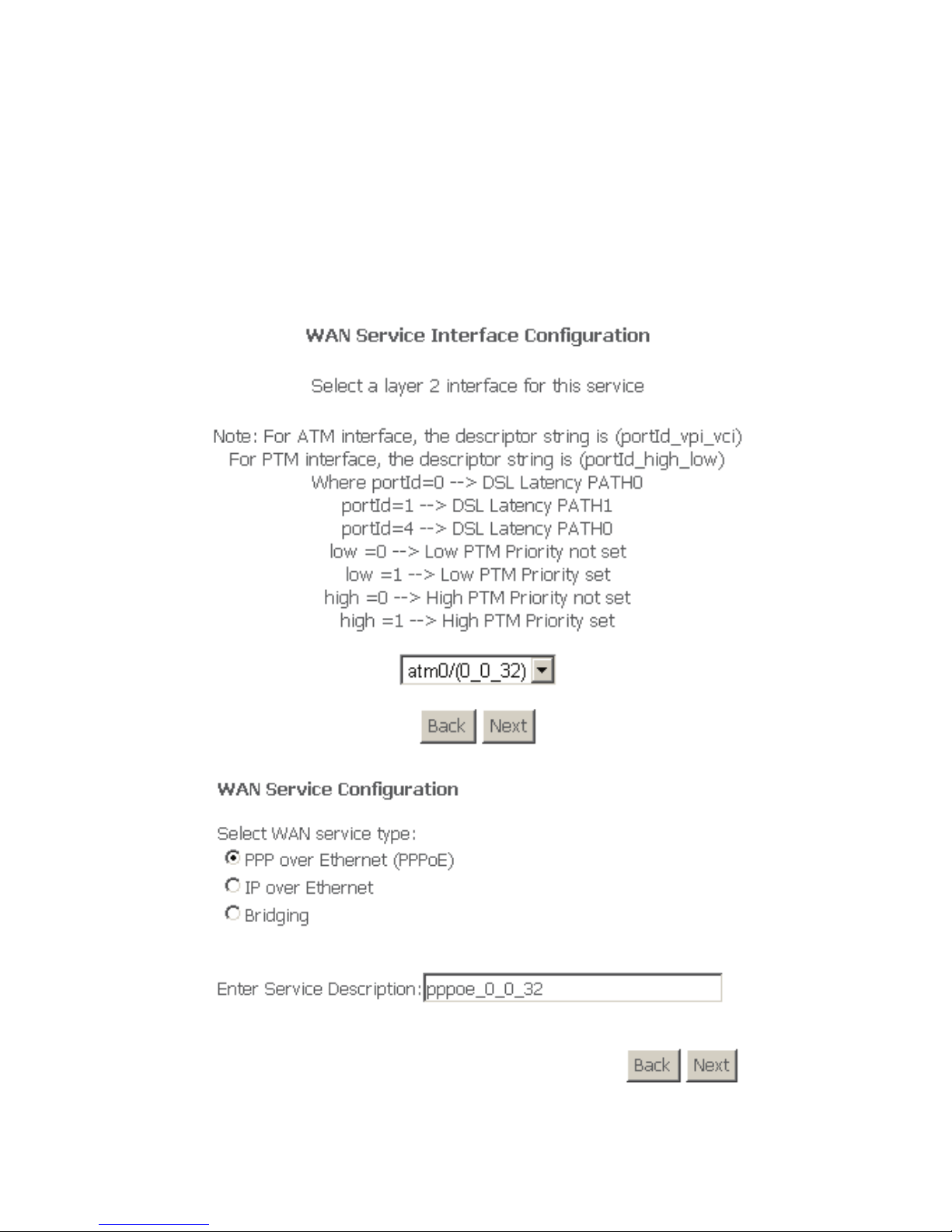
Step 1 Click Add to turn into the following page. (At first, you must add suitable
ATM configuration for this WAN configuration.) In this page, you can
select ATM Interface .
Step 2 After proper selection, click Next, and the following page appears.
Step 3 In this page, select WAN service type PPP over Ethernet(PPPoE). Click
Next, and the following page appears.
24
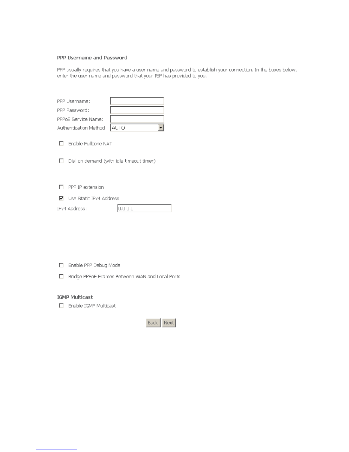
Step 4 In this page, you can modify the PPP username, PPP password, and
authentication method.
PPP Username: The correct user name that your ISP provides to you.
PPP Password: The correct password that your ISP provides to you.
PPPoE Service Name: If your ISP provides it to you, please enter it. If not,
do not enter any information.
Authentication Method: The value can be AUTO, PAP, CHAP, or MSCHAP.
Usually, you can select AUTO.

25
Enable Fullcone NAT: A full cone NAT is one where all requests from the
same internal IP address and port are mapped to the same external IP
address and port. Furthermore, any external host can send a packet to the
internal host, by sending a packet to the mapped external address.
Dial on demand (with idle timeout timer): If this function is enabled, you
need to enter the idle timeout time. Within the preset minutes, if the modem
does not detect the flow of the user continuously, the modem automatically
stops the PPPOE connection. Once it detects the flow (like access to a
webpage), the modem restarts the PPPoE dialup. If this function is disabled,
the modem performs PPPoE dial-up all the time. The PPPoE connnection
does not stop, unless the modem is powered off and DSLAM or uplink
equipment is abnormal.
PPP IP extension: After PPP IP extension is enabled, the WAN IP address
obtained by the modem through built-in dial-up can be directly assigned to
the PC being attached with the modem (at this time, the modem has only
one PC). From the view of the PC user, this is even with that the PC dials up
to obtain an IP addres. But actually, the dial-up is done by the modem. If this
function is disabled, the modem itself obtains the WAN IP address
automatically.
Use Static IPv4 Address: If this function is disabled, the modem obtains an
IP address assigned by an uplink equipment such as BAS, through PPPoE
dial-up. If this function is enabled, the modem uses this IP address as the
WAN IP address.
IGMP Multicast: IGMP proxy. For example, if you want PPPoE mode to
support IPTV, enable it.
After enter the PPP Username and PPP Password, click Next, and the following
page appears.
26
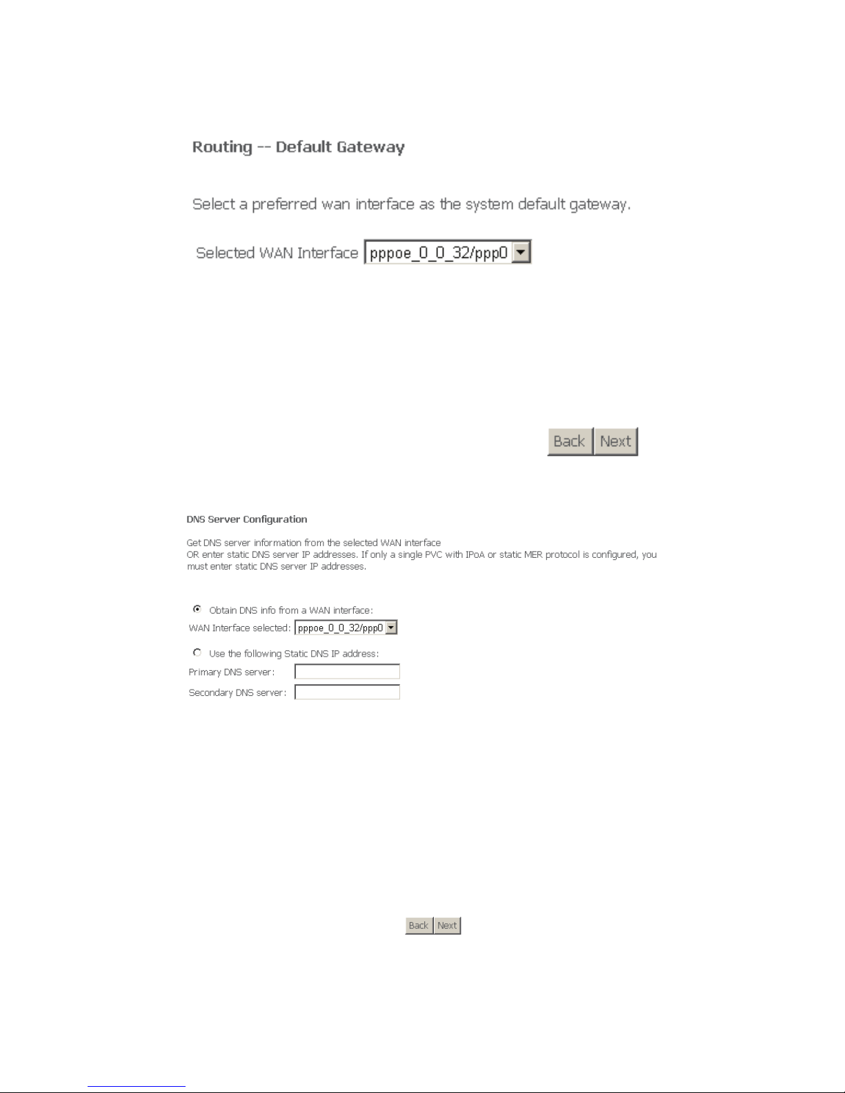
Step 5 In this page, select a preferred WAN interface as the system default
gateway. Click Next, and the following page appears.
Step 6 In this page, you can get DNS server information from the selected WAN
interface or enter static DNS server IP addresses. If only a single PVC
27
with IPoA or static MER protocol is configured, you must enter static
DNS server IP addresses. Click Next, and the following page appears.
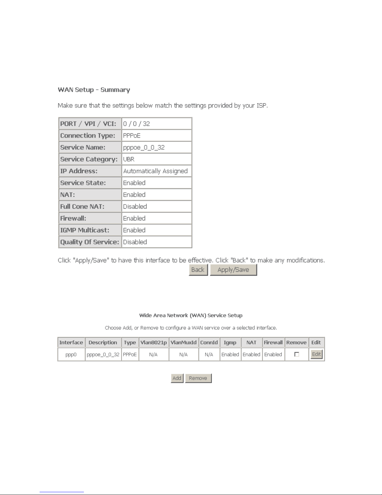
Step 7 In this page, it shows all the configurations. Click Apply/Save to all the
configurations, and the following page appears. Click Back to make any
modifications.
4.3.2.2 Adding a MER (IPoE) Configuration
In the WAN Service Setup page, click Add to add WAN configuration. This section
describes the procedure for adding ipoe_0_0_32 (Mer mode).
Step 1 Click Add to turn into the following page. (At first, you must add suitable
ATM configuration for this WAN configuration.)
 Loading...