

Page 1
This product can be set up using
any current web browser, i.e.,
Internet Explorer 6, Netscape
Navigator 6.2.3, Mozilla or Firefox.
DSL-584T
ADSL2+ Router
Before You Begin
Make sure you have all the necessary information and equipment on hand before beginning
the installation.
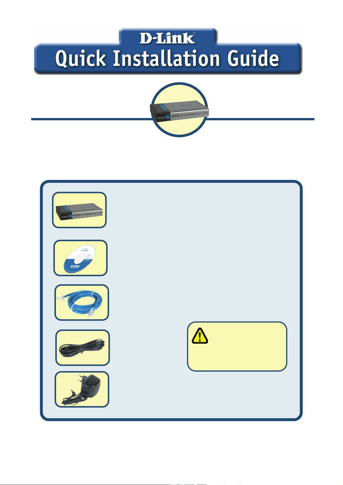
Check Your Package Contents
DSL-584T ADSL Router
CD-ROM (containing User Manual)
Ethernet (CAT5 UTP) Cable
Using a power supply
with a different voltage
Telephone
rating will damage and void
the warranty for this product.
If any of the above items is missing,
Power Adapter
©2005 D-Link Systems, Inc. All rights reserved. Trademarks or registered trademarks are the property of their respective holders.
Software and specifications subject to change without notice.
1
please contact your reseller.
Page 2
Connecting the Router to Your Computer
A. First, connect the power adapter to the receptor at the back panel of the
DSL-584T and then plug the other end of the power adapter to a wall outlet or
power strip. The Power LED will turn ON to indicate proper operation.
B. Insert one end of the Ethernet cable into any Ethernet port on the back panel of the
DSL-584T and the other end of the cable to an Ethernet Adapter or available Ethernet
port on your computer.
C. Insert one end of the Telephone cable into the ADSL port on the rear panel of the
Router and insert the other end into the wall socket. If you need to install a low pass
filter, follow the instructions of your ISP.
Connecting the DSL-584T to your network
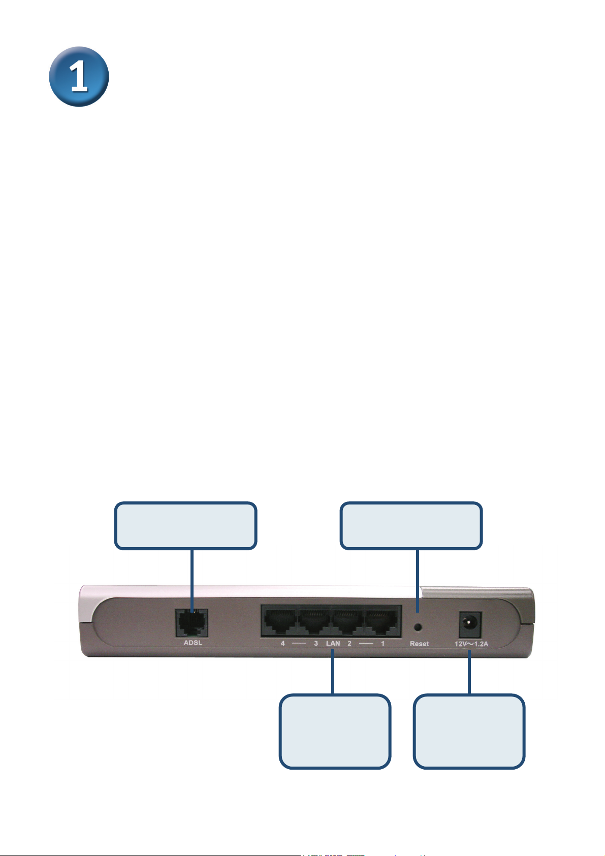
Rear Panel Connections
All cable connections to the Router are made at the rear panel. Connect the power adapter
here to power on the Router. Use the Reset button to restore the settings to the factory default
values in the next chapter for instructions on using the reset button.
ADSL port - connect
Factory reset button
to ADSL line
Ethernet ports -
connect to
Ethernet cable
2
Power input –
connect to power
adapter
Page 3
Connecting the Router to Your Computer
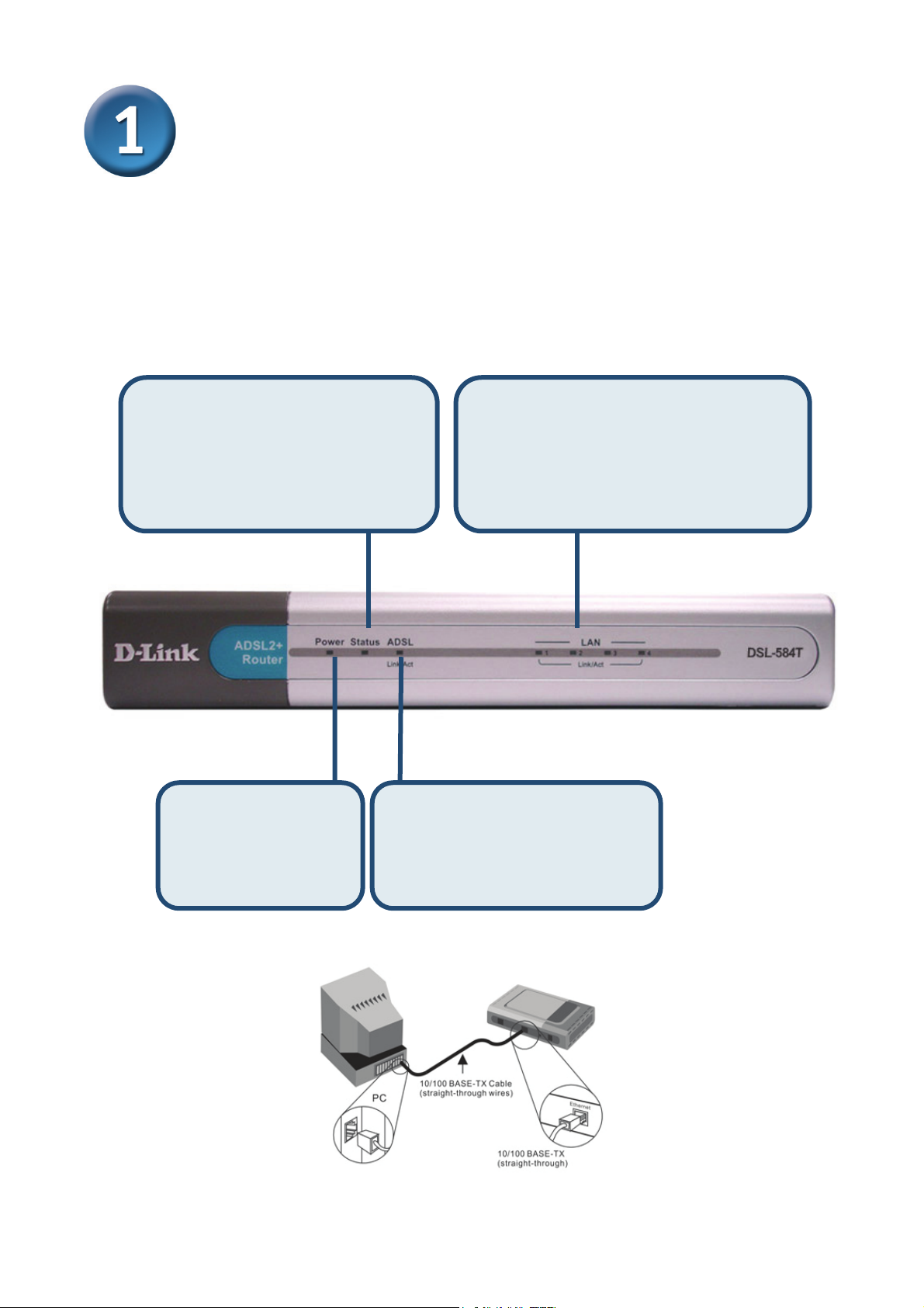
Front Panel Connections
The LED indicators on the front panel include the Power, Status, ADSL and Ethernet
indicators.
Status: A blinking green LED
indicates the device is in proper
working order. A system failure will
result in the LED lighting solid or
going dark.
Your setup should resemble the one shown below.
Power: a steady light
indicates the
DSL-584T is ready.
ADSL Link/Act: A steady
green light indicates a valid
ADSL connection. A blinking
LED will signify an active
WAN session
Ethernet Link/Act: A steady green light
indicates a valid Ethernet connection
while a blinking LED indicates an active
Ethernet session.
3
Page 4
Configuring the Router
You can select two methods to configure your new router. The first method is by using D-Link
Click’n Connect Utility, which is included on the CD designed to run on Windows XP/2000.
Just follow the instructions step by step to configure your router for Internet access for the first
time.
The second method is to use your Web browser to access the web pages used to setup the
Router, your computer must be configured to “Obtain an IP address automatically”, that is,
you must change the IP network settings of your computer so that it is a DHCP Client. If you
are using Windows XP and do not know how to change your network settings, skip ahead to
the Appendix and read the instructions provided. You may also read the User Manual for
instructions on changing IP settings for computers running Windows operating systems.
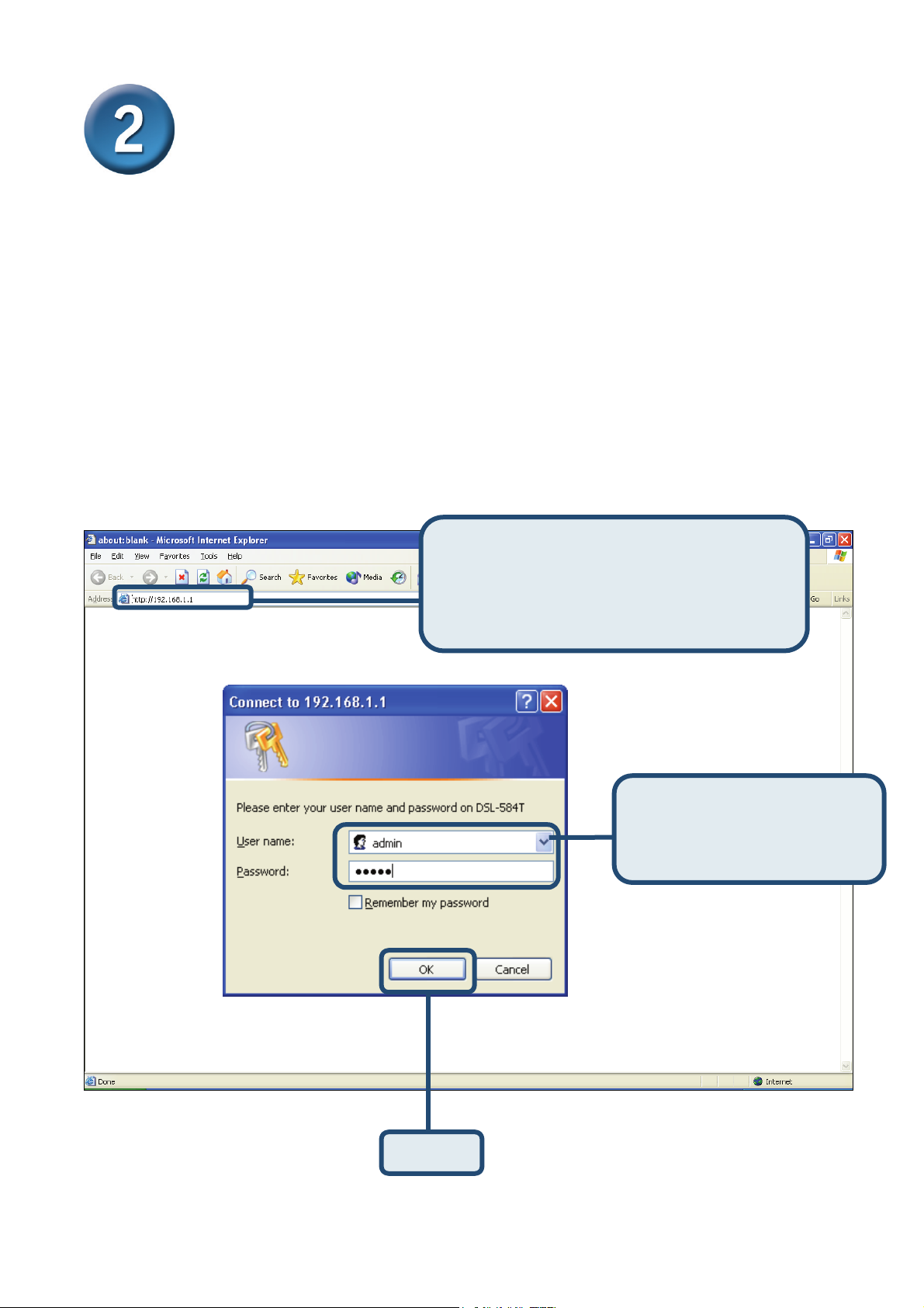
Open your Web browser and type
“http://192.168.1.1” into the URL address
box. Then press the Enter or Return key.
The Login page appears.
Type “admin” for the User
Name and “0000” in the
Password field.
Click OK
4
Page 5
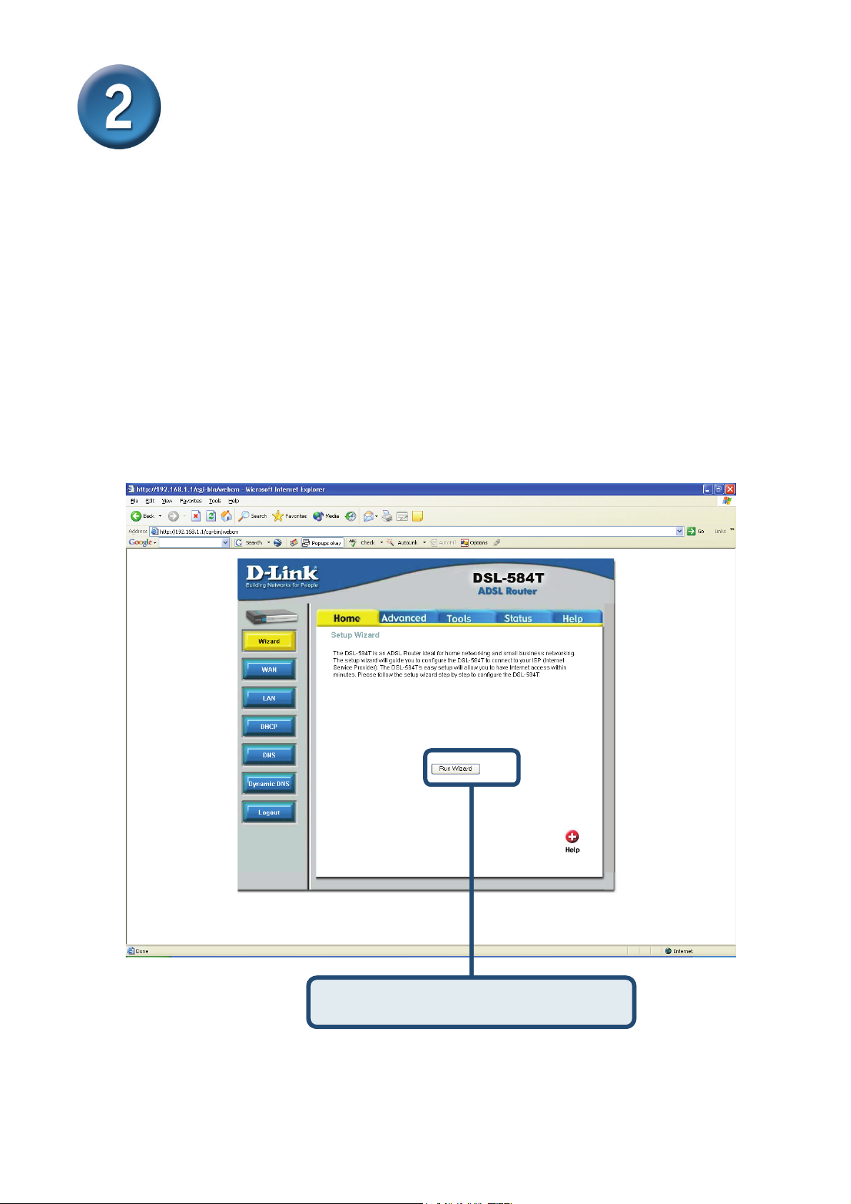
Configuring the Router (continued)
Once you have logged in, the Home directory tab is prominent with the Setup Wizard menu
displayed. Most users will be able to use the Setup Wizard to establish the ADSL connection
to your ISP. To begin using the Setup Wizard, click on the Run Wizard button in the middle of
the web page. A pop-up menu will appear. This pop-up menu is the Setup Wizard. The Setup
Wizard procedure consists of four general steps:
1. Choose your time zone
2. Set Internet Connection
3. Restart
When you setup the Internet connection, you will need to enter information provided by your
ISP. The type of information you need depends on the type of connection you are setting up.
Click on the Run Wizard button.
5
Page 6

Configuring the Router (continued)
The first Setup Wizard menu lists a summary of the steps required to complete the setup.
Click the Next button to begin setup.
Click the Next button.
6
Page 7

Configuring the Router (continued)
Now configure the Time Zone used for the Router’s system clock. Select the appropriate time
zone and Daylight Saving Time setting for your location.
Select the Time Zone you are located
in by using the pull-down menu.
Click the Next button.
7
Page 8

Configuring the Router (continued)
Next you will Set the Internet Connection Type for the WAN interface. Your ISP has given
this information to you. If you do not know what type of connection to use, exit the Setup
Wizard and contact your ISP for the information. The Setup wizard menu that appears when
you click the Next button depends on what connection type you select.
Select the Connection Type
used for your ADSL service.
Click the Next button.
8
Page 9

Configuring the Router (continued)
PPPoE/PPPoA Connections
If you selected the PPPoE/PPPoA connection type in the previous menu, you will see the
Setup Wizard menu pictured here. Type in the Username and Password used to identify and
verify your account to the ISP. Enter the VPI and VCI numbers that have been provided by
your ISP. Select the Connection Type used for encapsulation specific to your service. Click
Next when you are ready to continue to the Setup Completed menu.
If you are not sure what Connection Type, VPI and VCI to use, please check with your ISP.
Type the
Username
and
Password
for your ISP
account.
Choose the correct Connection Type from
the pull-down menu. The user may choose
between PPPoA VC-Mux, PPPoE LLC or
PPPoA LLC, as instructed by your ISP.
Enter the VPI
and VCI
numbers that
have been
provided by
your ISP.
Click the Next button. Skip ahead to
the Setup Completed menu below.
9
Page 10

Configuring the Router (continued)
Dynamic IP Address Connections
For this connection type, the user may choose Bridged IP LLC or Bridged IP VC-Mux. Both
of these connections require the user to have additional software located on their computer to
negotiate the connection with the ISP. Both Bridged modes will automatically set the network
connections. If you selected the Dynamic IP Address connection type, select the Connection
Type used for encapsulation and if you have been instructed to change the VPI number and
VCI number, type in the new values. Click Next when you are ready to continue the Setup
Completed menu.
Enter the
VPI and VCI
numbers that
have been
provided by
your ISP.
The Cloned MAC Address field is
used to copy the MAC Address of
your Ethernet Adapter to the router.
Enter the MAC Address into the
space provided and click the Clone
Mac Address button.
Select the
Encapsulation
as 1483
Bridged IP
LLC or 1483
Bridged IP
VcMux as
instructed by
your ISP.
Click the Next button to skip ahead
to the Setup Completed menu.
10
Page 11

Configuring the Router (continued)
Bridged Connections
Bridged is used to set the Bridged mode for the Router. This window is for users who have
software on their computer or other network device to take the connection from your ISP. You
may change the PVC (Permanent Virtual Channel) settings and the Connection Type.
Enter the VPI
and VCI numbers
that have been
provided by your
ISP.
Select the Connection Type as
1483 Bridged IP LLC or 1483
Bridged IP VC-Mux as instructed
by your ISP.
Click the Next button. Skip
ahead to the Setup Completed
menu below.
11
Page 12

Configuring the Router (continued)
Static IP Connections
Static IP is used to set the Static IP mode for the Router. Static IP is used whenever a known
static IP address is assigned. The accompanying information such as the Subnet mask and
the gateway should also be specified in order to be able to connect. These are the servers
would enable you to have access to other web servers. Information entered here must come
from your ISP. You may change the PVC (Permanent Virtual Channel) settings and the
Encapsulation.
Enter the VPI
and VCI
numbers that
have been
provided by
your ISP.
Type the IP addresses
for the WAN IP
Address, Subnet Mask,
ISP Gateway Address,
Primary DNS Address
and/or Secondary DNS
Address, as instructed
by your ISP.
Select the Connection Type as
1483 Bridged IP LLC, 1483
Bridged IP VC-Mux, 1483 Routed
IP LLC, 1483 Routed IP VC-Mux
or IPoA, as instructed by your ISP.
Click the Next button. Skip ahead to the Setup
Completed menu below.
12
Page 13

Configuring the Router (continued)
Setup Completed
All the settings for the ADSL connection are now completed. Click the Restart button to save
the new settings and restart the Router. It will take about two minutes to restart the Router.
The window pictured on the right appears
during the save and restart process.
Please do not turn off the Router while
it is still displayed!
Click the Restart button.
13
Page 14

Appendix
For additional settings or information, refer to the Advanced, Tools, or Status tabs on the
Web Management interface; or to the manual located on the CD-ROM.
Configuring IP Settings in Windows XP
Use the following steps to configure a computer running Windows XP to be a DHCP client.
1. From the Start menu on your desktop, go to Control Panel.
From the Start menu, go to
Control Panel.
2. In the Control Panel window, click Network and Internet Connections.
Click Network and
Internet Connections.
14
Page 15

3. In the Network and Internet Connections window, click Network Connections.
Click Network
Connections.
4. In the Network Connections window, right-click on Local Area Connection, then click
Properties.
Right-click on the Local Area
Connection icon and select the
Properties option from the
pull-down menu.
15
 Loading...