

Page 1

DSL-564T
(April ,2004)
ADSL Router
User’s Guide
Page 2

DSL-564T DSL Router User’s Guide
FCC Warning
This device complies with part 15 of the FCC Rules. Operation is subject to the following two conditions: (1)
This device may not cause harmful interference, and (2) this device must accept any interference received,
including interference that may cause undesired operation.
This equipment has been tested and found to comply with the limits for a Class B digital device, pursuant to part
15 of the FCC Rules. These limits are designed to provide reasonable protection against harmful interference in a
residential installation. This generates, uses and can radiate radio frequency energy and, if not installed and used
in accordance with the instructions, may cause harmful interference to radio communications. However, there is
no guarantee that interference will not occur in a particular installation. If this equipment does cause harmful
interference to radio or television reception, which can be determined by turning equipment off and on, the user
is encouraged to try to correct the interference by one or more of the following measures:
- Reorient or relocate the receiving antenna.
- Increase the separation between the equipment and receiver.
- Connect the equipment into an outlet on a circuit different from that to which the receiver is connected.
- Consult the dealer or an experienced radio/TV technician for help.
CE Mark Warning
This is a Class B product. In a domestic environment, this product may cause radio interference in which case
the user may be required to take adequate measures.
ii
Page 3

DSL-564T ADSL Router User’s Guide
Warranty and Registration for all Countries and
Regions Except USA
Wichtige Sicherheitshinweise
1. Bitte lesen Sie sich diese Hinweise sorgfä ltig durch.
2. Heben Sie diese Anleitung für den spä tern Gebrauch auf.
3. Vor jedem Reinigen ist das Gerä t vom Stromnetz zu trennen. Vervenden Sie keine Flü ssig- oder Aerosolreiniger. Am besten
dient ein angefeuchtetes Tuch zur Reinigung.
4. Um eine Beschä digung des Gerä tes zu vermeiden sollten Sie nur Zubehörteile verwenden, die vom Hersteller zugelassen sind.
5. Das Gerä t is vor Feuchtigkeit zu schützen.
6. Bei der Aufstellung des Gerä tes ist auf sichern Stand zu achten. Ein Kippen oder Fallen könnte Verletzungen hervorrufen.
Verwenden Sie nur sichere Standorte und beachten Sie die Aufstellhinweise des Herstellers.
7. Die Belüftungsöffnungen dienen zur Luftzirkulation die das Gerä t vor Ü berhitzung schützt. Sorgen Sie dafü r, daß diese
Ö ffnungen nicht abgedeckt werden.
8. Beachten Sie beim Anschluß an das Stromnetz die Anschluß werte.
9. Die Netzanschluß steckdose muß aus Gründen der elektrischen Sicherheit einen Schutzleiterkontakt haben.
10. Verlegen Sie die Netzanschluß leitung so, daß niemand darüber fallen kann. Es sollete auch nichts auf der Leitung abgestellt
werden.
11. Alle Hinweise und Warnungen die sich am Gerä ten befinden sind zu beachten.
12. Wird das Gerä t über einen lä ngeren Zeitraum nicht benutzt, sollten Sie es vom Stromnetz trennen. Somit wird im Falle einer
Ü berspannung eine Beschä digung vermieden.
13. Durch die Lüftungsöffnungen dürfen niemals Gegenstä nde oder Flü ssigkeiten in das Gerä t gelangen. Dies könnte einen
Brand bzw. Elektrischen Schlag auslösen.
14. Ö ffnen Sie niemals das Gerä t. Das Gerä t darf aus Gründen der elektrischen Sicherheit nur von authorisiertem
Servicepersonal geöffnet werden.
15. Wenn folgende Situationen auftreten ist das Gerä t vom Stromnetz zu trennen und von einer qualifizierten Servicestelle zu
überprüfen:
a. Netzkabel oder Netzstecker sint beschä digt.
b. Flüssigkeit ist in das Gerä t eingedrungen.
c. Das Gerä t war Feuchtigkeit ausgesetzt.
d. Wenn das Gerä t nicht der Bedienungsanleitung ensprechend funktioniert oder Sie mit Hilfe dieser Anleitung
keine Verbesserung erzielen.
e. Das Gerä t ist gefallen und/oder das Gehä use ist beschä digt.
f. Wenn das Gerä t deutliche Anzeichen eines Defektes aufweist.
16. Bei Reparaturen dürfen nur Orginalersatzteile bzw. den Orginalteilen entsprechende Teile verwendet werden. Der Einsatz von
ungeeigneten Ersatzteilen kann eine weitere Beschä digung hervorrufen.
17. Wenden Sie sich mit allen Fragen die Service und Repartur betreffen an Ihren Servicepartner. Somit stellen Sie die
Betriebssicherheit des Gerä tes sicher.
18. Zum Netzanschluß dieses Gerä tes ist eine geprüfte Leitung zu verwenden, Für einen Nennstrom bis 6A und einem
Gerä tegewicht grőßer 3kg ist eine Leitung nicht leichter als H05VV-F, 3G, 0.75mm2 einzusetzen.
WARRANTIES EXCLUSIVE
IF THE D-LINK PRODUCT DOES NOT OPERATE AS WARRANTED ABOVE, THE CUSTOMER'S SOLE REMEDY SHALL BE, AT DLINK'S OPTION, REPAIR OR REPLACEMENT. THE FOREGOING WARRANTIES AND REMEDIES ARE EXCLUSIVE AND ARE IN
LIEU OF ALL OTHER WARRANTIES, EXPRESSED OR IMPLIED, EITHER IN FACT OR BY OPERATION OF LAW, STATUTORY OR
OTHERWISE, INCLUDING WARRANTIES OF MERCHANTABILITY AND FITNESS FOR A PARTICULAR PURPOSE. D-LINK NEITHER
ASSUMES NOR AUTHORIZES ANY OTHER PERSON TO ASSUME FOR IT ANY OTHER LIABILITY IN CONNECTION WITH THE SALE,
INSTALLATION MAINTENANCE OR USE OF D-LINK'S PRODUCTS.
D-LINK SHALL NOT BE LIABLE UNDER THIS WARRANTY IF ITS TESTING AND EXAMINATION DISCLOSE THAT THE ALLEGED
DEFECT IN THE PRODUCT DOES NOT EXIST OR WAS CAUSED BY THE CUSTOMER'S OR ANY THIRD PERSON'S MISUSE,
NEGLECT, IMPROPER INSTALLATION OR TESTING, UNAUTHORIZED ATTEMPTS TO REPAIR, OR ANY OTHER CAUSE BEYOND
THE RANGE OF THE INTENDED USE, OR BY ACCIDENT, FIRE, LIGHTNING OR OTHER HAZARD.
iii
Page 4

DSL-564T DSL Router User’s Guide
LIMITATION OF LIABILITY
IN NO EVENT WILL D-LINK BE LIABLE FOR ANY DAMAGES, INCLUDING LOSS OF DATA, LOSS OF PROFITS, COST OF COVER
OR OTHER INCIDENTAL, CONSEQUENTIAL OR INDIRECT DAMAGES ARISING OUT THE INSTALLATION, MAINTENANCE, USE,
PERFORMANCE, FAILURE OR INTERRUPTION OF A D- LINK PRODUCT, HOWEVER CAUSED AND ON ANY THEORY OF LIABILITY.
THIS LIMITATION WILL APPLY EVEN IF D-LINK HAS BEEN ADVISED OF THE POSSIBILITY OF SUCH DAMAGE.
IF YOU PURCHASED A D-LINK PRODUCT IN THE UNITED STATES, SOME STATES DO NOT ALLOW THE LIMITATION OR
EXCLUSION OF LIABILITY FOR INCIDENTAL OR CONSEQUENTIAL DAMAGES, SO THE ABOVE LIMITATION MAY NOT APPLY TO
YOU.
Limited Warranty
Hardware:
D-Link warrants each of its hardware products to be free from defects in workmanship and materials under normal use and service
for a period commencing on the date of purchase from D-Link or its Authorized Reseller and extending for the length of time
stipulated by the Authorized Reseller or D-Link Branch Office nearest to the place of purchase.
This Warranty applies on the condition that the product Registration Card is filled out and returned to a D-Link office within ninety
(90) days of purchase. A list of D-Link offices is provided at the back of this manual, together with a copy of the Registration Card.
If the product proves defective within the applicable warranty period, D-Link will provide repair or replacement of the product.
D-Link shall have the sole discretion whether to repair or replace, and replacement product may be new or reconditioned.
Replacement product shall be of equivalent or better specifications, relative to the defective product, but need not be identical. Any
product or part repaired by D-Link pursuant to this warranty shall have a warranty period of not less than 90 days, from date of
such repair, irrespective of any earlier expiration of original warranty period. When D-Link provides replacement, then the defective
product becomes the property of D-Link.
Warranty service may be obtained by contacting a D-Link office within the applicable warranty period, and requesting a Return
Material Authorization (RMA) number. If a Registration Card for the product in question has not been returned to D-Link, then a
proof of purchase (such as a copy of the dated purchase invoice) must be provided. If Purchaser's circumstances require special
handling of warranty correction, then at the time of requesting RMA number, Purchaser may also propose special procedure as may
be suitable to the case.
After an RMA number is issued, the defective product must be packaged securely in the original or other suitable shipping package
to ensure that it will not be damaged in transit, and the RMA number must be prominently marked on the outside of the package.
The package must be mailed or otherwise shipped to D-Link with all costs of mailing/shipping/insurance prepaid. D-Link shall
never be responsible for any software, firmware, information, or memory data of Purchaser contained in, stored on, or integrated
with any product returned to D-Link pursuant to this warranty.
Any package returned to D-Link without an RMA number will be rejected and shipped back to Purchaser at Purchaser's expense,
and D-Link reserves the right in such a case to levy a reasonable handling charge in addition mailing or shipping costs.
Software:
Warranty service for software products may be obtained by contacting a D-Link office within the applicable warranty period. A list
of D-Link offices is provided at the back of this manual, together with a copy of the Registration Card. If a Registration Card for the
product in question has not been returned to a D-Link office, then a proof of purchase (such as a copy of the dated purchase invoice)
must be provided when requesting warranty service. The term "purchase" in this software warranty refers to the purchase
transaction and resulting license to use such software.
D-Link warrants that its software products will perform in substantial conformance with the applicable product documentation
provided by D-Link with such software product, for a period of ninety (90) days from the date of purchase from D-Link or its
Authorized Reseller. D-Link warrants the magnetic media, on which D-Link provides its software product, against failure during
the same warranty period. This warranty applies to purchased software, and to replacement software provided by D-Link pursuant
to this warranty, but shall not apply to any update or replacement which may be provided for download via the Internet, or to any
update which may otherwise be provided free of charge.
D-Link's sole obligation under this software warranty shall be to replace any defective software product with product which substantially conforms to D-Link's
applicable product documentation. Purchaser assumes responsibility for the selection of appropriate application and system/platform software and associated
reference materials. D-Link makes no warranty that its software products will work in combination with any hardware, or any application or system/platform
software product provided by any third party, excepting only such products as are expressly represented, in D-Link's applicable product documentation as being
compatible. D-Link's obligation under this warranty shall be a reasonable effort to provide compatibility, but D-Link shall have no obligation to provide
compatibility when there is fault in the third-party hardware or software. D-Link makes no warranty that operation of its software products will be uninterrupted
or absolutely error-free, and no warranty that all defects in the software product, within or without the scope of D-Link's applicable product documentation, will
be corrected.
iv
Page 5

DSL-564T ADSL Router User’s Guide
Warranty and Registration Information for USA Only
Subject to the terms and conditions set forth herein, D-Link Systems, Inc. (“D-Link”) provides this Limited warranty for its product
only to the person or entity that originally purchased the product from:
l D-Link or its authorized reseller or distributor and
l Products purchased and delivered within the fifty states of the United States, the District of Columbia, U.S. Possessions
or Protectorates, and U.S. Military Installations, addresses with an APO or FPO.
Limited Warranty: D-Link warrants that the hardware portion of the D-Link products described below will be free from material
defects in workmanship and materials from the date of original retail purchase of the product, for the period set forth below
applicable to the product type (“Warranty Period”), except as otherwise stated herein.
5-Year Limited Warranty for the Product(s) is defined as follows:
l Hardware (excluding power supplies and fans) Five (5) Years
l Power Supplies and Fans Three (3) Year
l Spare parts and spare kits Ninety (90) days
D-Link’s sole obligation shall be to repair or replace the defective Hardware during the Warranty Period at no charge to the original
owner or to refund at D-Link’s sole discretion. Such repair or replacement will be rendered by D-Link at an Authorized D-Link
Service Office. The replacement Hardware need not be new or have an identical make, model or part. D-Link may in its sole
discretion replace the defective Hardware (or any part thereof) with any reconditioned product that D-Link reasonably determines is
substantially equivalent (or superior) in all material respects to the defective Hardware. Repaired or replacement Hardware will be
warranted for the remainder of the original Warranty Period from the date of original retail purchase. If a material defect is
incapable of correction, or if D-Link determines in its sole discretion that it is not practical to repair or replace the defective
Hardware, the price paid by the original purchaser for the defective Hardware will be refunded by D-Link upon return to D-Link of
the defective Hardware. All Hardware (or part thereof) that is replaced by D-Link, or for which the purchase price is refunded, shall
become the property of D-Link upon replacement or refund.
Limited Software Warranty:
D-Link’s then current functional specifications for the Software, as set forth in the applicable documentation, from the date of
original retail purchase of the Software for a period of ninety (90) days (“Warranty Period”), provided that the Software is properly
installed on approved hardware and operated as contemplated in its documentation. D-Link further warrants that, during the
Warranty Period, the magnetic media on which D-Link delivers the Software will be free of physical defects. D-Link’s sole obligation
shall be to replace the non-conforming Software (or defective media) with software that substantially conforms to D-Link’s
functional specifications for the Software or to refund at D-Link’s sole discretion. Except as otherwise agreed by D-Link in writing,
the replacement Software is provided only to the original licensee, and is subject to the terms and conditions of the license granted
by D-Link for the Software. Software will be warranted for the remainder of the original Warranty Period from the date or original
retail purchase. If a material non-conformance is incapable of correction, or if D-Link determines in its sole discretion that it is not
practical to replace the non-conforming Software, the price paid by the original licensee for the non-conforming Software will be
refunded by D-Link; provided that the non-conforming Software (and all copies thereof) is first returned to D-Link. The license
granted respecting any Software for which a refund is given automatically terminates.
Non-Applicability of Warranty: The Limited Warranty provided hereunder for hardware and software of D-Link's products, will
not be applied to and does not cover any product purchased through the inventory clearance or liquidation sale or other sales in
which D-Link, the sellers, or the liquidators expressly disclaim their warranty obligation pertaining to the product and in that case,
the product is being sold "As-Is" without any warranty whatsoever including, without limitation, the Limited Warranty as described
herein, notwithstanding anything stated herein to the contrary.
Submitting A Claim: Any claim under this limited warranty must be submitted in writing before the end of the Warranty Period to
an Authorized D-Link Service Office.
The customer must submit as part of the claim a written description of the Hardware defect or Software nonconformance
l
in sufficient detail to allow D-Link to confirm the same.
l The original product owner must obtain a Return Material Authorization (“RMA”) number from the Authorized D-Link
Service Office and, if requested, provide written proof of purchase of the product (such as a copy of the dated purchase
invoice for the product) before the warranty service is provided.
l After an RMA number is issued, the defective product must be packaged securely in the original or other suitable
shipping package to ensure that it will not be damaged in transit, and the RMA number must be prominently marked on
the outside of the package. Do not include any manuals or accessories in the shipping package. D-Link will only replace
the defective portion of the Product and will not ship back any accessories.
l The customer is responsible for all shipping charges to D-Link. No Charge on Delivery (“COD”) is allowed. Products sent
COD will either be rejected by D-Link or become the property of D-Link. Products should be fully insured by the
customer and shipped to D-Link Systems, Inc., 17575 Mt. Herrmann, Fountain Valley, CA 92708. D-Link will not be
held responsible for any packages that are lost in transit to D-Link. The repaired or replaced packages will be shipped
via UPS Ground or any common carrier selected by D-Link, with shipping charges prepaid. Expedited shipping is
available if shipping charges are prepaid by the customer.
D-Link may reject or return any product that is not packaged and shipped in strict compliance with the foregoing requirements, or
for which an RMA number is not visible from the outside of the package. The product owner agrees to pay D-Link’s reasonable
handling and return shipping charges for any product that is not packaged and shipped in accordance with the foregoing
requirements, or that is determined by D-Link not to be defective or non-conforming.
What Is Not Covered:
subjected to abuse, accident, alteration, modification, tampering, negligence, misuse, faulty installation, lack of reasonable care,
D-Link warrants that the software portion of the product (“Software”) will substantially conform to
This limited warranty provided by D-Link does not cover: Products, if in D-Link’s judgment, have been
v
Page 6

DSL-564T DSL Router User’s Guide
repair or service in any way that is not contemplated in the documentation for the product, or if the model or serial number has
been altered, tampered with, defaced or removed; Initial installation, installation and removal of the product for repair, and shipping
costs; Operational adjustments covered in the operating manual for the product, and normal maintenance; Damage that occurs in
shipment, due to act of God, failures due to power surge, and cosmetic damage; Any hardware, software, firmware or other
products or services provided by anyone other than D-Link; Products that have been purchased from inventory clearance or
liquidation sales or other sales in which D-Link, the sellers, or the liquidators expressly disclaim their warranty obligation
pertaining to the product. Repair by anyone other than D-Link or an Authorized D-Link Service Office will void this Warranty.
Disclaimer of Other Warranties: EXCEPT FOR THE LIMITED WARRANTY SPECIFIED HEREIN, THE PRODUCT IS PROVIDED
“AS-IS” WITHOUT ANY WARRANTY OF ANY KIND WHATSOEVER INCLUDING, WITHOUT LIMITATION, ANY WARRANTY OF
MERCHANTABILITY, FITNESS FOR A PARTICULAR PURPOSE AND NON-INFRINGEMENT. IF ANY IMPLIED WARRANTY CANNOT
BE DISCLAIMED IN ANY TERRITORY WHERE A PRODUCT IS SOLD, THE DURATION OF SUCH IMPLIED WARRANTY SHALL BE
LIMITED TO NINETY (90) DAYS. EXCEPT AS EXPRESSLY COVERED UNDER THE LIMITED WARRANTY PROVIDED HEREIN, THE
ENTIRE RISK AS TO THE QUALITY, SELECTION AND PERFORMANCE OF THE PRODUCT IS WITH THE PURCHASER OF THE
PRODUCT.
Limitation of Liability: TO THE MAXIMUM EXTENT PERMITTED BY LAW, D-LINK IS NOT LIABLE UNDER ANY CONTRACT,
NEGLIGENCE, STRICT LIABILITY OR OTHER LEGAL OR EQUITABLE THEORY FOR ANY LOSS OF USE OF THE PRODUCT,
INCONVENIENCE OR DAMAGES OF ANY CHARACTER, WHETHER DIRECT, SPECIAL, INCIDENTAL OR CONSEQUENTIAL
(INCLUDING, BUT NOT LIMITED TO, DAMAGES FOR LOSS OF GOODWILL, LOSS OF REVENUE OR PROFIT, WORK STOPPAGE,
COMPUTER FAILURE OR MALFUNCTION, FAILURE OF OTHER EQUIPMENT OR COMPUTER PROGRAMS TO WHICH D-LINK’S
PRODUCT IS CONNECTED WITH, LOSS OF INFORMATION OR DATA CONTAINED IN, STORED ON, OR INTEGRATED WITH ANY
PRODUCT RETURNED TO D-LINK FOR WARRANTY SERVICE) RESULTING FROM THE USE OF THE PRODUCT, RELATING TO
WARRANTY SERVICE, OR ARISING OUT OF ANY BREACH OF THIS LIMITED WARRANTY, EVEN IF D-LINK HAS BEEN ADVISED
OF THE POSSIBILITY OF SUCH DAMAGES. THE SOLE REMEDY FOR A BREACH OF THE FOREGOING LIMITED WARRANTY IS
REPAIR, REPLACEMENT OR REFUND OF THE DEFECTIVE OR NON-CONFORMING PRODUCT. THE MAXIMUM LIABILITY OF DLINK UNDER THIS WARRANTY IS LIMITED TO THE PURCHASE PRICE OF THE PRODUCT COVERED BY THE WARRANTY. THE
FOREGOING EXPRESS WRITTEN WARRANTIES AND REMEDIES ARE EXCLUSIVE AND ARE IN LIEU OF ANY OTHER
WARRANTIES OR REMEDIES, EXPRESS, IMPLIED OR STATUTORY.
Governing Law: This Limited Warranty shall be governed by the laws of the state of California. Some states do not allow exclusion
or limitation of incidental or consequential damages, or limitations on how long an implied warranty lasts, so the foregoing
limitations and exclusions may not apply. This limited warranty provides specific legal rights and the product owner may also have
other rights which vary from state to state.
vi
Page 7

TABLE OF CONTENTS
About This User’s Guide....................................................................................................................................ix
Before You Start................................................................................................................................................ix
Installation Requirements...................................................................................................................................ix
INTRODUCTION........................................................................................................1
Router Description and Operation.......................................................................................................................1
Standards Compatibility and Compliance...........................................................................................................3
Front Panel Display.............................................................................................................................................4
Rear Panel Connections......................................................................................................................................5
HARDWARE INSTALLATION...................................................................................6
Power on Router..................................................................................................................................................6
Factory Reset Button...........................................................................................................................................6
Network Connections..........................................................................................................................................7
Power On Router.................................................................................................................................................8
Factory Reset Button...........................................................................................................................................8
BASIC ROUTER CONFIGURATION.........................................................................9
Configuring IP Settings on Your Computer........................................................................................................9
Access the Configuration Manager...................................................................................................15
Login to Home Page..........................................................................................................................................15
Configure the Router...........................................................................................................................16
Setup Menu.......................................................................................................................................................17
Configure Connection 1 for PPPoA..................................................................................................................18
Change the Connection Type.............................................................................................................20
Configure Connection 1 for PPPoE...................................................................................................................20
Configure Connection 1 for Bridge...................................................................................................................22
Configure Connection 1 for Static IP for WAN................................................................................................23
Configure Connection 1 for DHCP for WAN...................................................................................................25
Configure Connection 1 for CLIP.....................................................................................................................26
Create a New Connection....................................................................................................................27
DHCP Configuration for LAN..............................................................................................................30
Enable DHCP Relay..........................................................................................................................................31
Management IP.....................................................................................................................................32
Save Configuration Changes..............................................................................................................33
ADVANCED ROUTER MANAGEMENT..................................................................35
UPnP.................................................................................................................................................................36
LAN Clients......................................................................................................................................................37
Port Forwarding................................................................................................................................................38
Access Control..................................................................................................................................................42
Advanced Security............................................................................................................................................44
Bridge Filters.....................................................................................................................................................45
Multicast Pass-through......................................................................................................................................46
Static Routing....................................................................................................................................................47
Dynamic Routing..............................................................................................................................................48
Multiple Virtual Connections..............................................................................................................49
Tools and Utility Menus.......................................................................................................................50
User Management.............................................................................................................................................51
Page 8

System Commands............................................................................................................................................52
Remote Log.......................................................................................................................................................53
Update Gateway................................................................................................................................................54
Ping Test...........................................................................................................................................................55
Modem Test......................................................................................................................................................56
Status Menus........................................................................................................................................57
Network Statistics.............................................................................................................................................58
Connection Status..............................................................................................................................................59
DHCP Clients....................................................................................................................................................59
Modem Status....................................................................................................................................................60
Product Information..........................................................................................................................................60
System Log.......................................................................................................................................................61
Help Menu.........................................................................................................................................................61
TECHNICAL SPECIFICATIONS..............................................................................62
IP ADDRESS SETUP...............................................................................................64
IP CONCEPTS..........................................................................................................66
MICROFILTERS AND SPLITTERS..........................................................................69
Page 9

DSL-564T DSL Router User’s Guide
About This User’s Guide
This user’s guide provides instructions on how to install the DSL-564T ADSL Router and use it to connect a
computer or Ethernet LAN to the Internet.
If you are using a computer with a functioning Ethernet port, the quickest and easiest way to set up the DSL564T is to insert the Installation CD into the CD-ROM drive of your computer and follow the instructions
provided in the Quick Installation Guide.
Before You Start
Please read and make sure you understand all the prerequisites for proper installation of your new Router. Have
all the necessary information and equipment on hand before beginning the installation.
Installation Overview
The procedure to install the Router can be described in general terms in the following steps:
1. Gather information and equipment needed to install the device. Before you begin the actual installation
make sure you have all the necessary information and equipment.
2. Install the hardware, that is, connect the cables (Ethernet and telephone) to the device and connect the
power adapter.
3. Check the IP settings on your computer and change them if necessary so the computer can access the
web-based software built into the Router.
4. Use the web-based management software to configure the device to suit the requirements of your ADSL
account.
Installation Requirements
In order to establish a connection to the Internet it will be necessary to provide information to the Router that
will be stored in its memory. For some users, only their account information (Username and Password) is
required. For others, various parameters that control and define the Internet connection will be required. You can
print out the two pages below and use the tables to list this information. This way you have a hard copy of all the
information needed to setup the Router. If it is necessary to reconfigure the device, all the necessary information
can be easily accessed. Be sure to keep this information safe and private.
Low Pass Filters
Since ADSL and telephone services share the same copper wiring to carry their respective signals, a filtering
mechanism may be necessary to avoid mutual interference. A low pass filter device can be installed for each
telephone that shares the line with the ADSL line. These filters are easy to install passive devices that connect to
the ADSL device and/or telephone using standard telephone cable. Ask your service provider for more
information about the use of low pass filters with your installation.
Operating Systems
The DSL-564T uses an HTML-based web interface for setup and management. The web configuration manager
may be accessed using any operating system capable of running web browser software, including Windows 98
SE, Windows ME, Windows 2000, and Windows XP.
Web Browser
Any common web browser can be used to configure the Router using the web configuration management
software. The program is designed to work best with more recently released browsers such as Opera, Microsoft
Internet Explorer® version 5.0, Netscape Navigator® version 4.7, or later versions. The web browser must have
JavaScript enabled. JavaScript is enabled by default on many browsers. Make sure JavaScript has not been
ix
Page 10

DSL-564T DSL Router User’s Guide
disabled by other software (such as virus protection or web user security packages) that may be running on your
computer.
Ethernet Port (NIC Adapter)
Any computer that uses the Router must be able to connect to it through the Ethernet port on the Router. This
connection is an Ethernet connection and therefore requires that your computer be equipped with an Ethernet
port as well. Most notebook computers are now sold with an Ethernet port already installed. Likewise, most fully
assembled desktop computers come with an Ethernet NIC adapter as standard equipment. If your computer does
not have an Ethernet port, you must install an Ethernet NIC adapter before you can use the Router. If you must
install an adapter, follow the installation instructions that come with the Ethernet NIC adapter.
Additional Software
It may be necessary to install software on your computer that enables the computer to access the Internet.
Additional software must be installed if you are using the device a simple bridge. For a bridged connection, the
information needed to make and maintain the Internet connection is stored on another computer or gateway
device, not in the Router itself.
If your ADSL service is delivered through a PPPoE, PPPoA or CLIP (IPoA) connection, the information needed
to establish and maintain the Internet connection can be stored in the Router. In this case, it is not necessary to
install software on your computer. It may however be necessary to change some settings in the device, including
account information used to identify and verify the connection.
All connections to the Internet require a unique global IP address. For bridged connections, the global IP settings
must reside in a TCP/IP enabled device on the LAN side of the bridge, such as a PC, a server, a gateway device
such as a router or similar firewall hardware. The IP address can be assigned in a number of ways. Your network
service provider will give you instructions about any additional connection software or NIC configuration that
may be required.
About CLIP Connections (RFC 1577)
Classical IP over ATM (CLIP) connections may require global IP settings for the device. Your service provider
will give you IP settings information if needed. Some CLIP connections function like peer-to-peer connections
and therefore do not require IP settings on the WAN interface.
x
Page 11

DSL-564T DSL Router User’s Guide
Information you will need from your ADSL service provider:
Username
Password
Connection Protocol
Modulation Type
Security Protocol
VPI
VCI
This is the Username used to log on to your ADSL service
provider’s network. It is commonly in the form −
user@isp.com. Your ADSL service provider uses this to
identify your account.
This is the Password used, in conjunction with the Username
above, to log on to your ADSL service provider’s network.
This is used to verify the identity of your account.
This is the method your ADSL service provider uses to send
and receive data between the Internet and your computer.
Your Modem supports the following connection protocols:
PPPoE, PPPoA, PPPoA with DHCP, Bridge, and CLIP
(IPoA).
ADSL uses various standardized modulation techniques to
transmit data over the allotted signal frequencies. Some
users may need to change the type of modulation used for
their service. The default DSL modulation (MMODE) used for
the Router automatically detects all types of ADSL
modulation. However, if you are instructed to specify the
modulation type used for the Router, you have three
alternatives: G.LITE, G.DMT and T1.413
This is the method your ADSL service provider will use to
verify your Username and Password when you log on to their
network. Your Modem supports the PAP and CHAP
protocols.
This is the Virtual Path Identifier (VPI). It is used in
conjunction with the Virtual Channel Identifier (VCI) below, to
identify the data path between your ADSL service provider’s
network and your computer.
This is the Virtual Channel Identifier (VCI). It is used in
conjunction with the VPI above to identify the data path
between your ADSL service provider’s network and your
computer.
Record info here
Information you will need about your DSL-564T ADSL Router:
This is the Username needed access the Modem’s
Username
Password
LAN IP addresses for the
DSL-564T
LAN Subnet Mask for the
DSL-564T
xi
management interface. When you attempt to connect to the
device through a web browser you will be prompted to enter
this Username. The default Username for the Modem is
admin. This may be changed by the user.
This is the Password you will be prompted to enter when you
access the Modem’s management interface. The default
Password is admin. This may be changed by the user.
This is the IP address you will enter into the Address field of
your web browser to access the Modem’s configuration
graphical user interface (GUI) using a web browser. The
default IP address is 192.168.1.1 and it is referred to as the
“Management IP” address in this User’s Manual. This may be
changed to suit any IP address scheme the user desires. This
address will be the base IP address used for DHCP service
on the LAN when DHCP is enabled.
This is the subnet mask used by the DSL-564T, and will be
used throughout your LAN. The default subnet mask is
255.0.0.0. This can be changed later.
Record info here
Page 12

DSL-564T DSL Router User’s Guide
Information you will need about your LAN or computer:
Record info here
Ethernet NIC
DHCP Client status
If your computer has an Ethernet NIC, you can connect the
DSL-564T to this Ethernet port using an Ethernet cable.
You can also use the Ethernet port on the DSL-564T to
connect to other Ethernet devices, such as a Wireless
Access Point.
Your DSL-564T ADSL Modem is configured, by default, to
be a DHCP server. This means that it can assign an IP
address, subnet mask, and a default gateway address to
computers on your LAN. The default range of IP addresses
the DSL-564T will assign are from 192.168.1.2 to
192.168.1.254. Your computer (or computers) needs to be
configured to Obtain an IP address automatically (that is,
they need to be configured as DHCP clients.)
It is recommended that your collect and record this information here, or in some other secure place, in case you
have to re-configure your ADSL connection in the future.
Once you have the above information, you are ready to setup and configure your DSL-564T ADSL Router.
The Modem may be reset to its factory default settings by performing a Restore settings
operation within the management interface (see System Commands). If you cannot
gain access to the management interface, you may opt to use the Reset button on the
rear panel of the device).
Note
xii
Page 13

DSL-564T ADSL Router User’s Guide
1
Introduction
This section provides a brief description of the Router, its associated technologies and a list of Router features.
Router Description and Operation
The DSL-564T ADSL Router is designed to provide a simple and cost-effective ADSL Internet connection for
individual computers through the Ethernet ports, or use it to bridge your Ethernet LAN to the Internet. The DSL564T combines the benefits of high-speed ADSL technology and LAN IP management in one compact and
convenient package. ADSL technology enables many interactive multi-media applications such as video
conferencing and collaborative computing.
The Router is easy to install and use. The DSL-564T connects to computers or an Ethernet LAN via a standard
Ethernet interface. The ADSL connection is made using ordinary twisted-pair telephone line with standard
connectors. Multiple PCs can be networked and connected to the Internet using a single Wide Area Network
(WAN) interface and single global IP address.
The Router supports transparent bridging and can be used for IP packet routing over the Internet. Cost saving
features of the Router such as NAT (Network Address Translator) and DHCP (Dynamic Host Configuration
Protocol) improve administration efficiency and improve security for your private network. The advanced
security enhancements, packet filtering and port redirection, can help protect your network from potentially
devastating intrusions by malicious agents from outside your network.
What is ADSL?
Asymmetric Digital Subscriber Line (ADSL) is an access technology that utilizes ordinary copper telephone
lines to enable broadband high-speed digital data transmission and interactive multimedia applications for
business and residential customers.
ADSL greatly increases the signal carrying capacity of copper telephone lines without interfering with regular
telephone services. For the ADSL user, this means faster downloads and more reliable connectivity. ADSL
devices make it possible to enjoy benefits such as high-speed Internet access without experiencing any loss of
quality or disruption of voice/fax telephone capabilities.
ADSL provides a dedicated service over a single telephone line operating at speeds of up to 8 Mbps downstream
and up to 640 Kbps upstream, depending on local telephone line conditions. A secure point-to-point connection
is established between the user and the central office of the service provider.
D-Link ADSL devices incorporate the recommendations of the ADSL Forum regarding framing, data format,
and upper layer protocols.
1
Page 14

DSL-564T ADSL Router User’s Guide
Router Features
The DSL-564T ADSL Router utilizes the latest ADSL enhancements to provide a reliable Internet portal suitable
for most small to medium sized offices. DSL-564T advantages include:
•
PPP (Point-to-Point Protocol) Security – The DSL-564T ADSL Router supports PAP (Password
Authentication Protocol) and CHAP (Challenge Handshake Authentication Protocol) for PPP connections.
•
DHCP Support – Dynamic Host Configuration Protocol automatically and dynamically assigns al LAN IP
settings to each host on your network. This eliminates the need to reconfigure every host whenever changes
in network topology occur.
• Network Address Translation (NAT) – For small office environments, the DSL-564T allows multiple
users on the LAN to access the Internet concurrently through a single Internet account. This provides
Internet access to everyone in the office for the price of a single user.
NAT improves network security in effect by hiding the private network behind one global and visible IP
address. NAT address mapping can also be used to link two IP domains via a LAN-to-LAN connection.
• TCP/IP (Transfer Control Protocol/Internet Protocol) – The DSL-564T supports TCP/IP protocol, the
language used for the Internet. It is compatible with access servers manufactured by major vendors.
• RIP-1/RIP-2 – The DSL-564T supports both RIP-1 and RIP-2 exchanges with other routers. Using both
versions lets the Router to communicate with all RIP enabled devices.
• Static Routing – This allows you to select a data path to a particular network destination that will remain in
the routing table and never “age out”. If you wish to define a specific route that will always be used for data
traffic from your LAN to a specific destination within your LAN (for example to another router or a server)
or outside your network (to a ISP defined default gateway for instance).
• Default Routing – This allows you to choose a default path for incoming data packets for which the
destination address is unknown. This is particularly useful when if the Router functions as the sole
connection to the Internet.
•
ATM (Asynchronous Transfer Mode) – The DSL-564T supports Bridged Ethernet over ATM (RFC1483),
IP over ATM (RFC1577) and PPP over ATM (RFC 2364).
•
Precise ATM Traffic Shaping – Traffic shaping is a method of controlling the flow rate of ATM data cells.
This function helps to establish the Quality of Service for ATM data transfer.
•
G.hs (Auto-handshake) – This allows the Router to automatically choose either the G.lite or G.dmt ADSL
connection standards.
•
High Performance – Very high rates of data transfer are possible with the Router. Up to eight Mbps
downstream bit rate using the G.dmt.
•
Full Network Management – The DSL-564T incorporates SNMP (Simple Network Management Protocol)
support for web-based management and text-based network management via an RS-232 or Telnet
connection.
• Telnet Connection – The Telnet enables a network manager to access the Router’s management software
remotely.
• Easy Installation – The DSL-564T uses a web-based graphical user interface program for convenient
management access and easy set up. Any common web browser software can be used to manage the Router.
2
Page 15

DSL-564T ADSL Router User’s Guide
Standards Compatibility and Compliance
The DSL-564T complies with or is compatible with the following standards as recognized by their respective
agencies.
• ITU G.992.2 (G.lite “Splitterless ADSL”) compliant
• ITU-T Rec. I.361 compliant
•
RFC 791 Internet Protocol compliant
• RFC 792 UDP compliant
•
RFC 826 Address Resolution Protocol compliant (ARP) compliant
• RFC 1058 Routing Information Protocol (RIP) compliant
• RFC 1213 MIB II for IP compliant
•
RFC 1334 PPP Authentication Protocol compliant
• RFC 1389 Routing Information Protocol 2 (RIP2) compliant
•
RFC 1483 IP over AAL5/ Bridged Ethernet over AAL5 compliant
• RFC 1557 Classical IP over ATM (IPoA) compliant
• RFC 1661 Point to Point Protocol (PPP) compliant
•
RFC 1877 Automatic IP assignment compliant
• RFC 1994 Challenge Handshake Authentication Protocol compliant
• Supports RFC 2131 and RFC 2132 DHCP functions including: automatic assignment of IP address, use of
subnet mask and default gateway and provision of DNS server address for all hosts
• RFC 2364 PPP over ATM compliant (PPPoA) compliant
•
RFC 2516 PPP over Ethernet compliant (PPPoE) compliant
• RFC 2684 Bridged/Routed Ethernet over ATM compliant
•
IEEE 802.3 compliant
• IEEE 802.3u compliant
• IEEE 802.1d compliant
•
IEEE 802.3x compliant
• Embedded web server support
•
Supports Dynamic Learning
• Supports Static Routing
• Supports NAPT for up to 4096 connections
•
Supports DHCP for up to 253 hot connections
• Supports IGMP
•
Supports ATM Forum UNI 3.1/4.0
• Supports ATM VCC (Virtual Channel Circuit) for up to eight sessions
• Supports TELNET and TFTP
•
Supports back pressure for half-duplex
3
Page 16

DSL-564T ADSL Router User’s Guide
Packing List
Open the shipping carton and carefully remove all items. In addition to this User's Guide, ascertain that you have:
• One DSL-564T ADSL Router
•
One twisted-pair telephone cable used for ADSL connection
• One straight-through Ethernet cable
• One AC power adapter suitable for your electric service
•
An Installation CD-ROM containing this User’s Guide
Front Panel Display
Place the Router in a location that permits an easy view of the LED indicators on the front panel.
The LED indicators on the front panel include the Power, Status, ADSL Link/Act and LAN (1-4) Link/Act
indicators. The ADSL and Ethernet indicators monitor link status and activity (Link/Act).
Steady green light indicates the unit is
Power
Status
powered on. When the device is powered
off this remains dark.
Lights steady green during power on selftest (POST). Once the connection status
has been settled, the light will blink green. If
the indicator lights steady green after the
POST, the system has failed and the device
should be rebooted.
ADSL: Link/Act
LAN 1 - 4: Link/Act
Steady green light indicates a valid ADSL
connection. This will light after the ADSL
negotiation process has been settled. A
blinking green light indicates activity on the
WAN (ADSL) interface.
A solid green light indicates a valid link on
startup. These lights blink when there is
activity currently passing through the
Ethernet port.
4
Page 17
DSL-564T ADSL Router User’s Guide
connect ADSL
Power cord
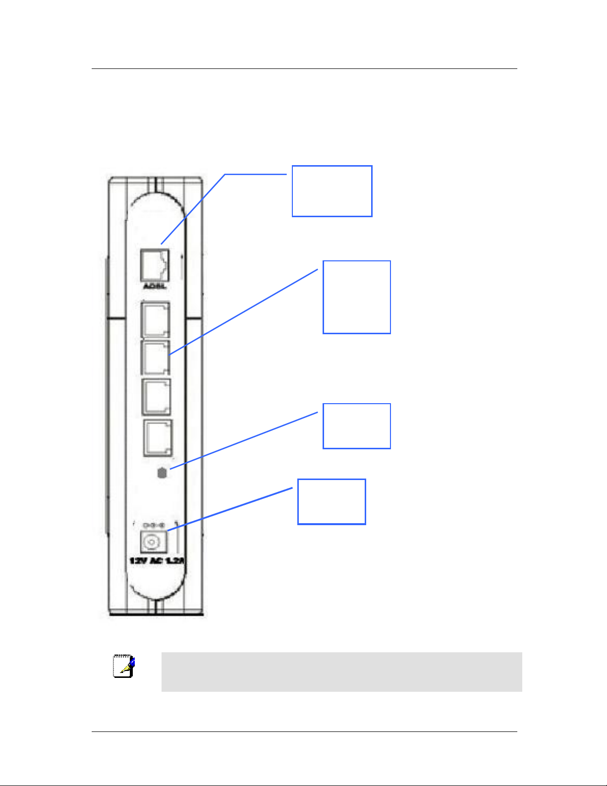
Rear Panel Connections
All cable connections to the Router are made at the rear panel. Connect the power adapter here to power on the
Router. Use the Reset button to restore the settings to the factory default values.
ADSL port,
cable here
Ethernet
ports,
connect
Ethernet
cable here
Factory
Reset
button
Note
The Router may be rebooted by disconnecting and then reconnecting the power.
connects
here
5
Page 18

DSL-564T ADSL Router User’s Guide
2
Hardware Installation
The DSL-564T maintains five separate interfaces, four Ethernet and one ADSL interface. Place the Router in a
location where it can be safely connected to the various devices as well as to a power source. The Router should
not be located where it will be exposed to moisture or excessive heat. Make sure the cables and power cord are
placed safely out of the way so they do not create a tripping hazard. As with any electrical appliance, observe
common sense safety precautions.
The Router can be placed on a shelf or desktop, ideally you should be able to see the LED indicators on the front
if you need to view them for troubleshooting.
Power on Router
CAUTION: The Router must be used with the power adapter included with the device.
To power on the Router:
1. Insert the AC Power Adapter cord into the power receptacle located on the rear panel of the Router and plug
the adapter into a suitable nearby power source.
2. You should see the Power LED indicator light up and remain lit. The Status LED should light solid green
and begin to blink after a few seconds.
3. If the Ethernet port is connected to a working device, check the Ethernet Link/Act LED indicators to make
sure the connection is valid. The Router will attempt to establish the ADSL connection, if the ADSL line is
connected and the Router is properly configured this should light up after several seconds. If this is the first
time installing the device, some settings may need to be changed before the Router can establish a
connection.
Factory Reset Button
The Router may be reset to the original factory default settings by depressing the reset button for a few seconds
while the device is powered on. Use a ballpoint or paperclip to gently push down the reset button. Remember
that this will wipe out any settings stored in flash memory including user account information and LAN IP
settings. The factory default IP address of the Router is 192.168.1.1 and the subnet mask is 255.255.255.0, the
default management Username is admin and the default Password is admin.
6
Page 19
DSL-564T ADSL Router User’s Guide
If you wish to reserve the
port on the switch or
hub for another device,
connect to any on the other
X ports (1x, 2x, etc.)
Network Connections
Network connections are provided through the ADSL port and the four Ethernet ports on the back of the Router.
See the Rear Panel diagram above and the illustrations below for examples.
Connect ADSL Line
Use the ADSL cable included with the Router to connect it to a telephone wall socket or receptacle. Plug one end
of the cable into the ADSL port (RJ-11 receptacle) on the rear panel of the Router and insert the other end into
the RJ-11 wall socket. If you are using a low pass filter device, follow the instructions included with the device
or given to you by your service provider. The ADSL connection represents the WAN interface, the connection to
the Internet. It is the physical link to the service provider’ s network backbone and ultimately to the Internet.
Connect Router to Ethernet
The Router may be connected to a single computer or Ethernet device through the 10BASE-TX Ethernet port on
the rear panel. Any connection to an Ethernet concentrating device such as a switch or hub must operate at a
speed of 10/100 Mbps only. When connecting the Router to any Ethernet device that is capable of operating at
speeds higher than 10Mbps, be sure that the device has auto-negotiation (NWay) enabled for the connecting port.
Use standard twisted-pair cable with RJ-45 connectors. The RJ-45 port on the Router is a crossed port (MDI-X).
Follow standard Ethernet guidelines when deciding what type of cable to use to make this connection. When
connecting the Router directly to a PC or server use a normal straight-through cable. You should use a crossed
cable when connecting the Router to a normal (MDI-X) port on a switch or hub. Use a normal straight-through
cable when connecting it to an uplink (MDI-II) port on a hub or switch.
The rules governing Ethernet cable lengths apply to the LAN to Router connection. Be sure that the cable
connecting the LAN to the Router does not exceed 100 meters.
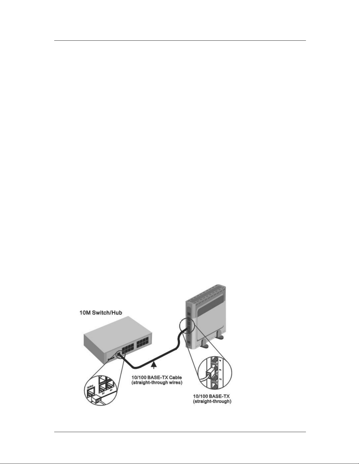
Hub or Switch to Router Connection
Connect the Router to an uplink port on an Ethernet hub or switch with a straight-through cable as shown in the
diagram below:
uplink
MDIwith a crossed cable.
7
Page 20
DSL-564T ADSL Router User’s Guide
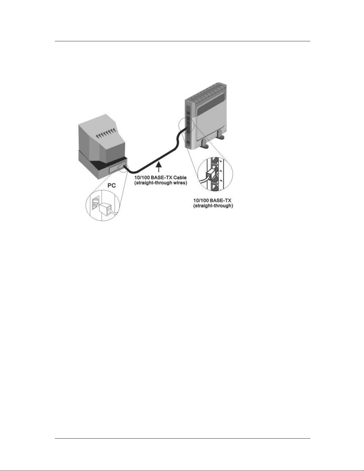
Computer to Router Connection
You can connect the
Router directly to a
10/100BASE-TX
Ethernet adapter card
(NIC) installed on a
PC using the Ethernet
cable provided as
shown in this diagram.
Power On Router
To power on the Router:
1. Insert the AC Power Adapter cord into the power receptacle located on the rear panel of the Router and plug
the adapter into a suitable nearby power source.
2. You should see the Power LED indicator light up and remain lit. The Status LED should light solid green
and begin to blink after a few seconds.
3. If you have the Router connected to your network you can look at the Ethernet Link/Act LED indicators to
make sure they have valid connections. The Router will attempt to establish the ADSL connection, if the
ADSL line is connected and the connection is properly configured this should light up after several seconds.
Factory Reset Button
The Router may be reset to the original factory default settings by depressing the reset button for a few seconds
while the device is powered on. Use a ballpoint or paperclip to push down the reset button. Remember that this
will wipe out any settings stored in flash memory including IP settings. The factory default IP address of the
Router is 192.168.1.1 and the subnet mask is 255.255.255.0.
8
Page 21

DSL-564T ADSL Router User’s Guide
3
Basic Router Configuration
The first time you setup the Router it is recommended that you configure the WAN connection using a single
computer making sure that both the computer and the Router are not connected to the LAN. Once the WAN
connection is functioning properly, you may continue to make changes to Router configuration including IP
settings and DHCP setup. This chapter is concerned with using your computer to configure the WAN connection.
The following chapter describes the various menus used to configure and monitor the Router including how to
change IP settings and DHCP server setup.
Wan Configuration Summary
1. Connect to the Router To configure the WAN connection used by the Router it is first necessary to
communicate with the Router through its management interface, which is HTML-based and can be
accessed using a web browser. To access the management software your computer must be able to
“see” the Router. Your computer can see the Router if it is in the same “neighborhood” or subnet as the
Router. This is accomplished by making sure your computer has IP settings that place it in the same
subnet as the Router. The easiest way to make sure your computer has the correct IP settings is to
configure it to use the DHCP server in the Router. The next section describes how to change the IP
configuration for a computer running a Windows operating system to be a DHCP client.
2. Configure the WAN Connection Once your are able to access the configuration software you can
proceed to change the settings required to establish the ADSL connection and connect to the service
provider’s network. There are different methods used to establish the connection to the service
provider’s network and ultimately to the Internet. You should know what Encapsulation and connection
type you are required to use for your ADSL service. It is also possible that you must change the PVC
settings used for the ADSL connection. Your service provider should provide all the information you
need to configure the WAN connection.
Configuring IP Settings on Your Computer
In order to configure your system to receive IP settings from the Router it must first have the TCP/IP protocol
installed. If you have an Ethernet port on your computer, it probably already has TCP/IP protocol installed. If
you are using Windows XP the TCP/IP is enabled by default for standard installations. Below is an illustrated
example of how to configure a Windows XP system to automatically obtain IP settings from the Router.
Following this example is a step-by-step description of the procedures used on the other Windows operating
systems to first check if the TCP/IP protocol has been installed; if it is not, instructions are provided for
installing it. Once the protocol has been installed you can configure the system to receive IP settings from the
Router.
For computers running non-Windows operating systems, follow the instructions for your OS that configure the
system to receive an IP address from the Router, that is, configure the system to be a DHCP client.
If you are using this Router to provide Internet access for more than one computer, you
Note
can use these instructions later to change the IP settings for the other computers.
However, you cannot use the same IP address since every computer must have its own
IP address that is unique on the local network.
9
Page 22

DSL-564T ADSL Router User’s Guide
Configure Windows XP for DHCP
Use the following steps to configure a computer running Windows XP to be a DHCP client.
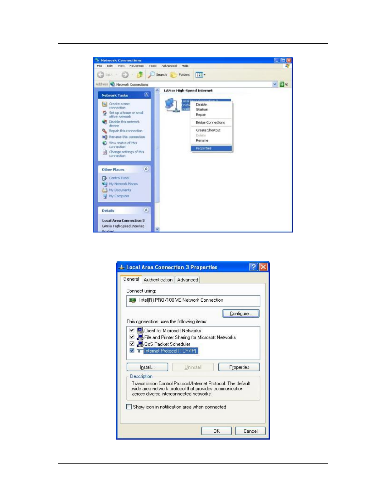
1. From the Start menu on your desktop, go to Settings, then click on Network Connections.
2. In the
Network Connections
Properties.
window, right-click on
10
(Local Area Connection), then click
LAN
Page 23
DSL-564T ADSL Router User’s Guide
3. In the General tab of the Local Area Connection Properties menu, highlight Internet Protocol
(TCP/IP)
under “This connection uses the following items:” by clicking on it once. Click on the
Properties button.
11
Page 24
DSL-564T ADSL Router User’s Guide
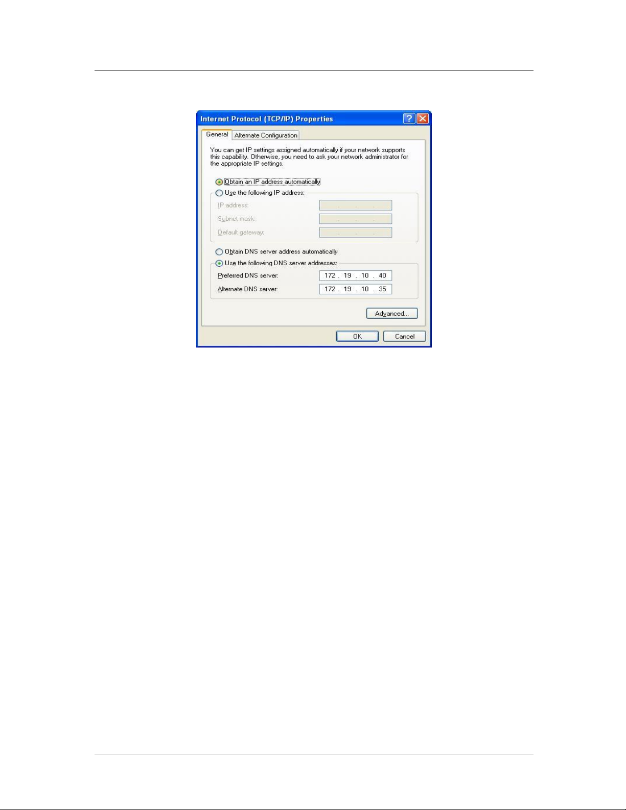
4. Select “Obtain an IP address automatically” by clicking once in the circle. Click the OK button.
Your computer is now ready to use the Router’s DHCP server.
Windows 2000
First, check for the IP protocol and, if necessary, install it:
1. In the Windows task bar, click the Start button, point to Settings, and then click Control Panel.
2. Double-click the Network and Dial-up Connections icon.
3. In the Network and Dial-up Connections window, right-click the Local Area Connection icon, and
then select Properties.
4. The Local Area Connection Properties dialog box displays with a list of currently installed network
components. If the list includes Internet Protocol (TCP/IP), then the protocol has already been enabled,
skip ahead to Configure Windows 2000 for DHCP.
5. If Internet Protocol (TCP/IP) does not display as an installed component, click Install.
6. In the Select Network Component Type dialog box, select Protocol, and then click Add.
7. Select Internet Protocol (TCP/IP) in the Network Protocols list, and then click OK.
8. You may be prompted to install files from your Windows 2000 installation CD or other media. Follow
the instructions to install the files.
9. If prompted, click OK to restart your computer with the new settings.
Configure Windows 2000 for DHCP
1. In the Control Panel, double-click the Network and Dial-up Connections icon.
2. In Network and Dial-up Connections window, right-click the Local Area Connection icon, and then
select Properties.
3. In the Local Area Connection Properties dialog box, select Internet Protocol (TCP/IP), and then
click Properties.
4. In the Internet Protocol (TCP/IP) Properties dialog box, click the button labeled Obtain an IP
address automatically.
5. Double-click OK to confirm and save your changes, and then close the Control Panel.
Your computer is now ready to use the Router’s DHCP server.
12
Page 25

DSL-564T ADSL Router User’s Guide
Windows ME
First, check for the IP protocol and, if necessary, install it:
1. In the Windows task bar, click the Start button, point to Settings, and then click Control Panel.
2. Double-click the Network and Dial-up Connections icon.
3. In the Network and Dial-up Connections window, right-click the Network icon, and then select
Properties.
4. The Network Properties dialog box displays with a list of currently installed network components. If
the list includes Internet Protocol (TCP/IP), then the protocol has already been enabled. Skip ahead to
Configure Windows ME for DHCP.
5. If Internet Protocol (TCP/IP) does not display as an installed component, click Add.
6. In the
7. Select Microsoft in the Manufacturers box.
8. Select Internet Protocol (TCP/IP) in the Network Protocols list, and then click OK.
9. You may be prompted to install files from your Windows Me installation CD or other media. Follow
10. If prompted, click OK to restart your computer with the new settings.
Select Network Component Type
the instructions to install the files.
dialog box, select
Protocol
, and then click
Add
.
Configure Windows ME for DHCP
1. In the Control Panel, double-click the Network and Dial-up Connections icon.
2. In the Network and Dial-up Connections window, right-click the Network icon, and then select
Properties.
3. In the Network Properties dialog box, select TCP/IP, and then click Properties.
4. In the
5. Double-click OK twice to confirm and save your changes, and then close the Control Panel.
Your computer is now ready to use the Router’s DHCP server.
TCP/IP Settings
dialog box, click the
Obtain and IP address automatically
option.
Windows 95 and Windows 98
First, check for the IP protocol and, if necessary, install it:
1. In the Windows task bar, click the Start button, point to Settings, and then click Control Panel.
Double-click the Network icon.
2. The Network dialog box displays with a list of currently installed network components. If the list
includes TCP/IP, and then the protocol has already been enabled, skip to Configure IP Information
Windows 95, 98.
3. If TCP/IP does not display as an installed component, click Add. The Select Network Component
Type dialog box displays.
4. Select Protocol, and then click Add. The Select Network Protocol dialog box displays.
5. Click on Microsoft in the Manufacturers list box, and then click TCP/IP in the Network Protocols list
box.
6. Click OK to return to the Network dialog box, and then click OK again. You may be prompted to
install files from your Windows 95/98 installation CD. Follow the instructions to install the files.
7. Click OK to restart the PC and complete the TCP/IP installation.
13
Page 26

DSL-564T ADSL Router User’s Guide
Configure Windows 95 and Windows 98 for DHCP
1. Open the Control Panel window, and then click the Network icon.
2. Select the network component labeled TCP/IP, and then click Properties.
3. If you have multiple TCP/IP listings, select the listing associated with your network card or adapter.
4. In the TCP/IP Properties dialog box, click the IP Address tab.
5. Click the Obtain an IP address automatically option.
6. Double-click OK to confirm and save your changes. You will be prompted to restart Windows.
7. Click Yes.
When it has restarted your computer is ready to use the Router’s DHCP server.
Windows NT 4.0 Workstations
First, check for the IP protocol and, if necessary, install it:
1. In the Windows NT task bar, click the Start button, point to Settings, and then click Control Panel.
2. In the Control Panel window, double-click the Network icon.
3. In the Network dialog box, click the Protocols tab.
4. The Protocols tab displays a list of currently installed network protocols. If the list includes TCP/IP,
then the protocol has already been enabled. Skip to “ Configure IP Information”
5. If TCP/IP does not display as an installed component, click Add.
6. In the Select Network Protocol dialog box, select TCP/IP, and then click OK. You may be prompted
to install files from your Windows NT installation CD or other media. Follow the instructions to install
the files.
7. After all files are installed, a window displays to inform you that a TCP/IP service called DHCP can be
set up to dynamically assign IP information.
8. Click Yes to continue, and then click OK if prompted to restart your computer.
Configure Windows NT 4.0 for DHCP
1. Open the Control Panel window, and then double-click the Network icon.
2. In the
3. In the Protocols tab, select TCP/IP, and then click Properties.
4. In the Microsoft TCP/IP Properties dialog box, click the Obtain an IP address automatically option.
5. Click OK twice to confirm and save your changes, and then close the Control Panel.
Network
dialog box, click the
Protocols
tab.
14
Page 27
DSL-564T ADSL Router User’s Guide
Access the Configuration Manager
Now that your computer’ s IP settings allow it to communicate with the Router, you can access the configuration
software.
Be sure that the web browser on your computer is not configured to use a proxy server
in the Internet settings. In Windows Internet Explorer, you can check if a proxy server is
enabled using the following procedure:
1. In Windows, click on the Start button, go to Settings and choose Control Panel.
Note
To use the web-based management software, launch a suitable web browser and direct it to the IP address of the
Router. Type in http:// followed by the default IP address, 192.168.1.1 in the address bar of the browser. The
URL in the address bar should read: http://192.168.1.1.
2. In the Control Panel window, double-click on the Internet Options icon.
3. Click the
4. Verify that the “Use proxy server” option is NOT checked. If it is checked, click in the
checked box to deselect the option and click OK.
Alternatively, you can access this Internet Options menu using the Tools pull-down
menu in Internet Explorer.
Connections
tab and click on the
LAN Settings
button.
Login to Home Page
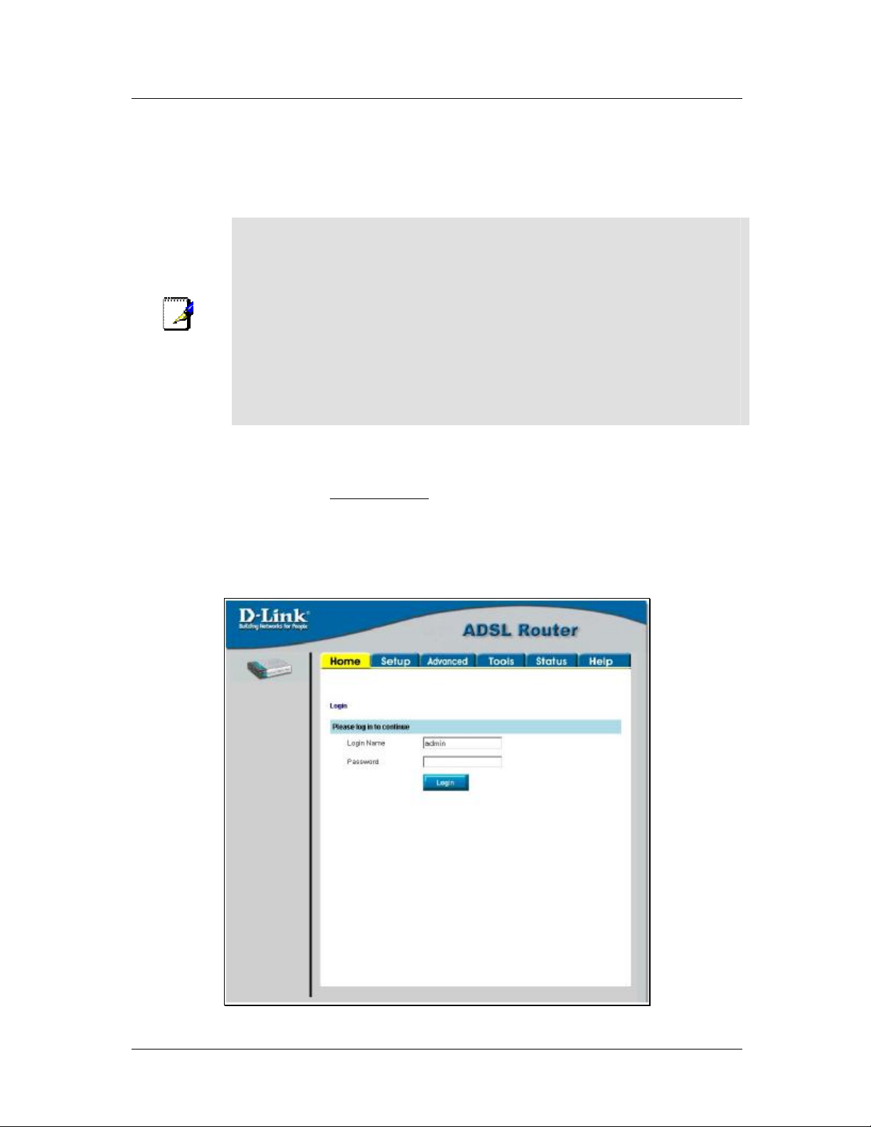
A new window will appear and you will be prompted for a user name and password to access the web-based
manager.
Figure 3-1. Home - Login window
15
Page 28

DSL-564T ADSL Router User’s Guide
Use the default user name admin and password admin for first time setup. You should change the web-based
manager access user name and password once you have verified that a connection can be established. The user
name and password allows any PC within the same subnet as the Modem to access the web-based manger.
Do not confuse the user name and password used to access the web-based manager
Note
with the ADSL account user name and password needed for PPP connections to
access the service provider’s network.
Configure the Router
The first page that appears after you successfully login displays information about the Router and its connection
status. Tabs across the top of the screen show other available menus: Setup, Advanced, Tools, Status, and Help.
Figure 3-2. Home – Status Information window
When the Router is used to provide Internet access it actually must first access your service provider’ s network,
that is, it must communicate with computers and other routers owned by your service provider. These computers
and routers then provide access to the Internet. The Router must be configured to communicate with the systems
that give it access to the larger network. Click either the Setup tab (or the Go to setup wizard hyperlink); the
Setup window will appear.
16
Page 29

DSL-564T ADSL Router User’s Guide
Setup Menu
The Setup window offers links to menus to configure settings for the LAN (Local Area Network) and for the
WAN (Wide Area Network) setup. The first menu you see when clicking the Setup tab or the Go to setup
wizard hyperlink is the Setup menu.
Now you are ready to configure the settings needed for the WAN connection. All the information you need to
make the changes needed for a functioning WAN connection should have been provided to you by your ISP or
network service provider.
Figure 3-3. Opening Setup window
If you are not instructed to change the modulation type, click the Connection 1 button or hyperlink to configure
the other WAN settings. Skip ahead to Configure Connection 1 for PPPoA below to configure a PPPoA
connection type. For other connection types such as PPPoE, CLIP (IPoA) or Bridge type connections, read
Change the Connection Type to first change the connection type used by the Router.
If you are instructed to change the method of modulation used for ADSL, click the Modem Setup button or
Modem Setup hyperlink and select the Modulation Type used for the connection. Skip ahead to the next page for
an example of the Modem Setup menu. Then proceed to Configure Connection to configure a PPPoA conection
or Change the Connection Type for other connection types.
17
Page 30

DSL-564T ADSL Router User’s Guide
DSL (Modulation) Settings
The DSL Setup menu is used to change the Modulation Type used for the ADSL connection. This setting should
only be changed if your service provider has given explicit instructions to change it.
Note
Do not change the (ADSL) Modulation type used unless you have been instructed to do
so. If this setting is not configured properly, the Router will not work.
Figure 3-4. DSL Setup menu (change modulation type)
If you are instructed by your ISP to change the Modulation type is used for your service, select the desired
modulation type and then click Apply. The modulation types available are T1413, G.DMT, GLITE and
MMODE. By default, the Router will automatically detect the modulation used; this setting is listed as MMODE
(Multi-mode).
Configure Connection 1 for PPPoA
PPP or Point-to-Point protocol is a standard method of establishing a network connection/session between
networked devices. Different forms of PPP include PPPoA and PPPoE (discussed below) involve an
authentication process that requires a username and password to gain access to the network. PPPoA (PPP over
ATM) as described in RFC 2364, is a method of using PPP on an ATM network. ATM is used for many types of
telecommunications services including ADSL.
18
Page 31

DSL-564T ADSL Router User’s Guide
To configure the WAN connection for PPPoA, perform the steps listed below. Some of the settings do not need
to be changed the first time the device is set up, but can be changed later if you choose.
Figure 3- 5. PPPoA Connection 1 Setup menu
To configure the default connection type (PPPoA) for Connection 1, follow the steps listed below. To change the
connection type of Connection 1 to an alternative type follow the instructions according to the desired type as
described below in Change the Connection Type.
1. Click the Connection 1 button under WAN Setup to view the PPPoA Connection Setup menu
pictured in the example above.
2. Type in a Name for the connection or use the default name conn_1_PPPoA_8_35 in the space provided.
3. Under Options, enable NAT and/or Firewall by selecting the corresponding selection box.
4. If you are told to change the VPI or VCI values, type in the values given to you by your service
provider. Many users will be able to use the default settings.
5. Leave the default QoS values if you are unsure or the ISP did not provide this information.
6. Do not change the PCR or SCR values unless you are required to do so. If you are told to change these,
type in the values given to you by your service provider.
7. Type the Username and Password used to verify the identity of your account. Typically, the Username
is an account number assigned by your ISP and appears in the form account#@serviceprovider.com,
while the Password may have been chosen by the account holder. For most users, the remaining settings
will not need to be changed. See your ISP for further information.
19
Page 32

DSL-564T ADSL Router User’s Guide
8. Click the Apply button when you have entered all the information. The web browser will briefly go
blank. You are now finished changing setting for the primary WAN connection known as Connection 1.
It is now necessary to save the changes you just made and restart the Router.
9. To save the changes made to Connection 1, click the Tools tab and then click on the System
Commands button. Click on the Save All button to store the configuration settings. Click on Back
button to return to the System Commands menu.
10. Check the WAN connection status. Click the Status tab and then the Connection Status button. Look
under WAN to view the State of Connection 1, it should read Connected. If the WAN connection state
does not appear to Connected after a few minutes, go back to the Connection 1 Setup menu, check the
settings and make sure they are correct.
Change the Connection Type
The default connection protocol used for the Router is Point-to-Point Protocol over ATM (PPPoA). The menu
used to configure a PPPoA connection is the first menu to appear when you click on the Connection 1 button in
the Setup menu. The alternative connection types supported by the Router are the PPPoE (PPP over Ethernet),
CLIP (Classical IP over ATM or IPoA), DHCP (for WAN), Static (IP for WAN), and Bridge connection types.
There are two ways you may configure the WAN connection to use these alternative types. You can create a
New Connection using the alternative connection type or you may configure the Connection 1 settings to use the
connection type of choice. This section describes how to change the Connection 1 settings to use a different
connection type. To change the Connection 1 settings to use a different connection type, follow the instructions
below according to the type of connection you want to use. To create and configure a New Connection, skip
ahead to Create a New Connection.
Configure Connection 1 for PPPoE
PPP or Point-to-Point protocol is a standard method of establishing a network connection/session between
networked devices. PPPoE configuration requires the same basic information as the previously discussed PPPoA
and both menus are nearly identical. It may be worthwhile for the user to change the default name of Connection
1 to something that states what connection type is being used, for example, conn_1_pppoe_8_35, the name used
in the example below. Notice the VPI and VCI values are included in the name. It is not functionally necessary
to change the name of the connection, this is done merely to provide descriptive reference.
20
Page 33

DSL-564T ADSL Router User’s Guide
Figure 3-6. Setup – Configure Connection 1 for PPPoE
To configure Connection 1 for PPPoE, follow the steps listed below. Some of the settings do not need to be
changed the first time the device is set up, but can be changed later if you choose.
1. Click the Connection 1 button under WAN Setup to view the default PPPoA Connection Setup
configuration menu.
2. Select PPPoE from the Type: pull-down menu. The menu will blink momentarily
3. Type in a Name: for the connection or use the default name in the space provided
(conn_1_PPPoE_8_35 used in the above example).
4. Under
5. If you are told to change the VPI or VCI values, type in the values given to you by your service
6. Leave the default QoS values if you are unsure or the ISP did not provide this information.
7. Do not change the PCR or SCR values unless you are required to do so. If you are told to change these,
8. Type the Username and Password used to verify the identity of your account. Typically, the Username
9. Click the Apply button when you have entered all the information. The web browser will briefly go
Options
provider. Many users will be able to use the default settings.
type in the values given to you by your service provider.
is an account number assigned by your ISP and appears in the form account#@serviceprovider.com,
while the Password may have been chosen by the account holder. For most users, the remaining settings
will not need to be changed. See your ISP for further information.
blank. You are now finished changing setting for the primary WAN connection known as Connection 1.
It is now necessary to save the changes you just made and restart the Router.
, enable
NAT
and/or
Firewall
by selecting the corresponding selection box.
10. To save the changes made to Connection 1, click the
Commands button. Click on the Save All button to store the configuration settings. Click on Back
button to return to the System Commands menu.
21
tab and then click on the
Tools
System
Page 34

DSL-564T ADSL Router User’s Guide
11. Check the WAN connection status. Click the Status tab and then the Connection Status button. Look
under WAN to view the State of Connection 1, it should read Connected. If the WAN connection state
does not appear to Connected after a few minutes, go back to the Connection 1 Setup menu, check the
settings and make sure they are correct.
Configure Connection 1 for Bridge
“Bridge” means a pure bridged connection with no IP address assigned to the Router. This connection method
makes the Router act as a bridge, and just passes packets across the DSL port. When the device is used in this
manner, it is necessary to install additional connection software on any computer or server used to access the
Internet.
Figure 3-7. Setup – Configure Connection 1 for Bridge
To configure the WAN connection for Bridge, perform the steps listed below. Some of the settings do not need
to be changed the first time the device is set up, but can be changed later if you choose.
1. Click the Connection 1 button under WAN Setup to view the default PPPoA Connection Setup
configuration menu.
2. Select Bridge from the Type: pull-down menu. This action will change the menu so it offers fewer
settings for configuration.
3. Type in a Name: in the space provided (conn_1_Bridge_8_35 is used in the above example).
4. If you are told to change the VPI or VCI values, type in the values given to you by your service
provider. Many users will be able to use the default settings.
5. Leave the default QoS values if you are unsure or the ISP did not provide this information.
22
Page 35

DSL-564T ADSL Router User’s Guide
6. Do not change the PCR or SCR values unless you are required to do so. If you are told to change these,
type in the values given to you by your service provider.
7. The Encapsulation values LLC (SNAP) and VC (MUX) are two different methods of encapsulating
the PPP packet. Contact your ISP to make sure which encapsulation is being supported.
8. Click the Apply button when you have entered all the information. The web browser will briefly go
blank. You are now finished changing setting for the primary WAN connection known as Connection 1.
It is now necessary to save the changes you just made and restart the Router.
9. To save the changes made to Connection 1, click the Tools tab and then click on the System
Commands button. Click on the Save All button to store the configuration settings. Click on Back
button to return to the System Commands menu.
10. Check the WAN connection status. Click the Status tab and then the Connection Status button. Look
under
does not appear to Connected after a few minutes, go back to the Connection 1 Setup menu, check the
settings and make sure they are correct.
WAN
to view the
of Connection 1, it should read Connected. If the WAN connection state
State
Configure Connection 1 for Static IP for WAN
Static is used whenever a known static IP is assigned. The accompanying information such as the Subnet mask
and the gateway should also be specified in order to be able to connect. Up to three Domain Name Server (DNS)
addresses can also be specified. These are the servers would enable you to have access to other web servers.
Valid IP addresses range from 1.0.0.1 to 223.255.255.254.
Figure 3-8. Setup – Configure Connection 1 for Static IP for the WAN
23
Page 36

DSL-564T ADSL Router User’s Guide
To configure the WAN connection for Static, perform the steps listed below. Some of the settings do not need to
be changed the first time the device is set up, but can be changed later if you choose.
1. Click the Connection 1 button under WAN Setup to view the default PPPoA Connection Setup
configuration menu.
2. Select Static from the Type: pull-down menu. This action will change the menu so it offers different
settings for configuration.
3. Type in a Name: in the space provided (conn_1_Static_8_35 is used in the above example).
4. If you are told to change the VPI or VCI values, type in the values given to you by your service
provider. Many users will be able to use the default settings.
5. Leave the default QoS values if you are unsure or the ISP did not provide this information.
6. Do not change the PCR or SCR values unless you are required to do so. If you are told to change these,
type in the values given to you by your service provider.
7. The Encapsulation values LLC (SNAP) and VC (MUX) are two different methods of encapsulating
the PPP packet. Contact your ISP to make sure which encapsulation is being supported.
8. Based on the information provided by your ISP, enter the IP Address, Subnet Mask, Default Gateway
(if provided), and Domain Name Services (
) values (if provided).
DNS
9. Select the desired
10. Click the Apply button when you have entered all the information. The web browser will briefly go
blank. You are now finished changing setting for the primary WAN connection known as Connection 1.
It is now necessary to save the changes you just made and restart the Router.
11. To save the changes made to Connection 1, click the Tools tab and then click on the System
Commands button. Click on the Save All button to store the configuration settings. Click on Back
button to return to the System Commands menu.
12. Check the WAN connection status. Click the Status tab and then the Connection Status button. Look
under WAN to view the State of Connection 1, it should read Connected. If the WAN connection state
does not appear to Connected after a few minutes, go back to the Connection 1 Setup menu, check the
settings and make sure they are correct.
Mode, Bridged
or
Routed
.
24
Page 37

DSL-564T ADSL Router User’s Guide
Configure Connection 1 for DHCP for WAN
Dynamic Host Configuration Protocol (DHCP) allows the gateway to automatically obtain the IP address from a
DHCP server on the service provider’ s network. The service provider assigns a global IP address from a pool of
addresses available to the service provider. Typically the IP address assigned has a long lease time, so it will
likely be the same address each time the Router requests an IP address.
Figure 3-9. Setup – Configure Connection 1 for DHCP service for the WAN
To configure the WAN connection for DHCP, perform the steps listed below. Some of the settings do not need
to be changed the first time the device is set up, but can be changed later if you choose.
1. Click the Connection 1 button under WAN Setup to view the default PPPoA Connection Setup
configuration menu.
2. Select DHCP from the Type: pull-down menu. This action will change the menu so it offers different
settings for configuration.
3. Type in a Name: in the space provided (conn_1_DHCP_8_35 is used in the above example).
4. If you are told to change the VPI or VCI values, type in the values given to you by your service
provider. Many users will be able to use the default settings.
5. Leave the default QoS values if you are unsure or the ISP did not provide this information.
6. Do not change the PCR or SCR values unless you are required to do so. If you are told to change these,
type in the values given to you by your service provider.
7. The Encapsulation values LLC (SNAP) and VC (MUX) are two different methods of encapsulating
the PPP packet. Contact your ISP to make sure which encapsulation is being supported.
25
Page 38

DSL-564T ADSL Router User’s Guide
8. Click the Apply button when you have entered all the information. The web browser will briefly go
blank. You are now finished changing setting for the primary WAN connection known as Connection 1.
It is now necessary to save the changes you just made and restart the Router.
9. To save the changes made to Connection 1, click the Tools tab and then click on the System
Commands button. Click on the Save All button to store the configuration settings. Click on Back
button to return to the System Commands menu.
10. Check the WAN connection status. Click the Status tab and then the Connection Status button. Look
under WAN to view the State of Connection 1, it should read Connected. If the WAN connection state
does not appear to Connected after a few minutes, go back to the Connection 1 Setup menu, check the
settings and make sure they are correct.
Configure Connection 1 for CLIP
CLIP or IPoA connections function in a similar way to DHCP or Static IP connections. Certain CLIP
connections function like P2P networks. The router must obtain IP settings from a server owned by an ISP, or
use a static IP address assigned by the ISP.
Figure 3-10. Setup – Configure Connection 1 for CLIP (IPoA)
To configure the WAN connection for CLIP, perform the steps listed below. Some of the settings do not need to
be changed when you first set up the device but can be changed later if you choose.
1. Click the Connection 1 button under WAN Setup to view the default PPPoA Connection Setup
configuration menu.
2. Select CLIP from the
settings for configuration.
pull-down menu. This action will change the menu so it offers different
Type:
26
Page 39
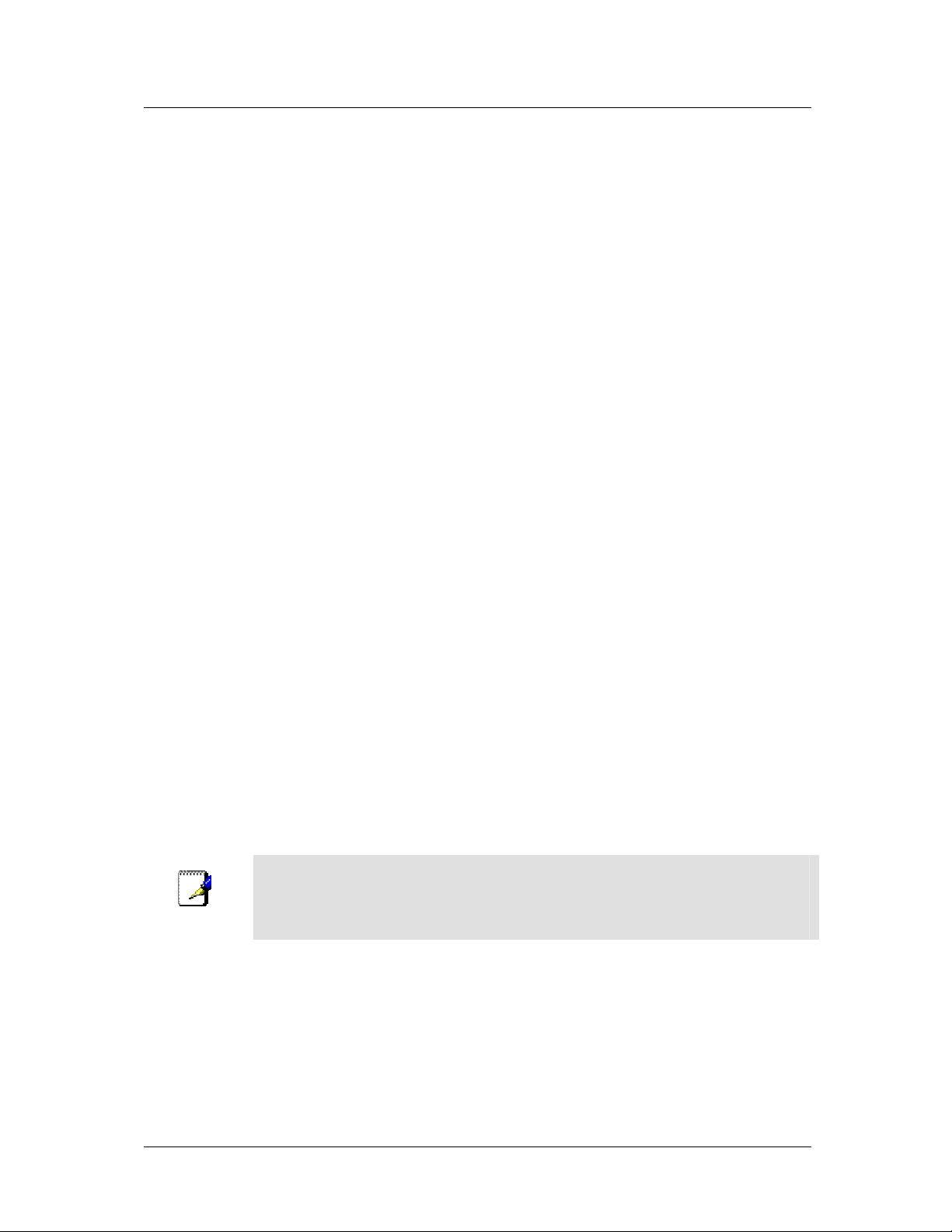
DSL-564T ADSL Router User’s Guide
3. Type in a
4. Under Options, enable NAT and/or Firewall by selecting the appropriate checkbox. This option is not
available for a Bridge connection.
5. Based upon the information your ISP provided, enter the IP Address (e.g. 168.128.1.1), the Subnet
Mask (e.g. 255.255.255.0), ARP Server (e.g. 168.128.1.2) and the Default Gateway (e.g.
168.128.1.254).
6. If you are told to change the VPI or VCI values, type in the values given to you by your service
provider. Many users will be able to use the default settings.
7. Leave the default QoS values if you are unsure or the ISP did not provide this information.
8. Do not change the PCR or SCR values unless you are required to do so. If you are told to change these,
type in the values given to you by your service provider.
9. Click the Apply button when you have entered all the information. The web browser will briefly go
blank. You are now finished changing setting for the primary WAN connection known as Connection 1.
It is now necessary to save the changes you just made and restart the Router.
in the space provided (conn_1_CLIP_8_35 is used in the above example).
Name:
10. To save the changes made to Connection 1, click the
Commands button. Click on the Save All button to store the configuration settings. Click on Back
button to return to the System Commands menu.
11. Check the WAN connection status. Click the Status tab and then the Connection Status button. Look
under WAN to view the State of Connection 1, it should read Connected. If the WAN connection state
does not appear to Connected after a few minutes, go back to the Connection 1 Setup menu, check the
settings and make sure they are correct.
tab and then click on the
Tools
System
Create a New Connection
An alternative method of changing the connection type used by the Router is to create a new connection.
Creating a new connection will not change the Connection 1 settings, it will make a new set of coneciton
configuration settings. The new set created will be labeled Connection 2, additional connections created will be
likewise labeled Connection 3, Connection 4 and so on. Use the method described here to create up to 8 different
connection configuration sets. At any time you may reconfigure the settings for any previously created
connection by clicking on the menu button for the connection displayed under the WAN Setup heading.
Use the New Connection procedure to create new connection used for accounts that
Note
supports multiple virtual connections. For more information on creating and maintaining
virtual connection, see Multiple Virtual Connections in the following chapter on
Advanced Router Management.
27
Page 40

DSL-564T ADSL Router User’s Guide
New Connection Example 1 - Create a New PPPoE Connection
The example below describes how to set up a new connection that uses a PPPoE type WAN conneciton. To
create a new connection:
1. Click on the New Connection button.
2. Configure the Router for the Type: of conneciton used and all the remaining settings as discussed in the
preceding section. In this example, the type of connection used for Connection 2 is PPPoE. Notice also
the the VPI and VCI values have been changed.
3. Click the Apply button to cerate the new connection. Notice that a new menu button is created
(Connection 2), this links to the configuration menu for Connection 2 (see example below). If at any
time you want to change, delete, disconnect or connect this WAN connection, click on the Connection 2
button.
4. Remember to save any newly created connections using the Save All procedure in the Tools/System
Commands menu.
5. To delete the connection, click the Delete button.
Figure 3- 11. Setup a New Connection – Connection 2
28
Page 41

DSL-564T ADSL Router User’s Guide
New Connection Example 2 - Create a New Bridge Connection
You may create new connections to suit different purposes. For example, let’ s create a new Bridge connection
used to connect directly to a server acting as a firewall and proxy.
1. Click the New Connection button.
2. Select Bridge from the Type: menu.
3. Configure the remaining settings (including VPI: and VCI:) as necessary.
4. Click the Apply button. Notice that a new menu button, Connection 3, appears under WAN Setup.
5. Remember to save any newly created connections using the Save All procedure in the Tools/System
Commands menu.
6. To delete the connection, click the Delete button.
Figure 3- 12. Setup a New Connection – Connection 3
29
Page 42

DSL-564T ADSL Router User’s Guide
DHCP Configuration for LAN
The Router supports three DHCP modes for the LAN. By default, DHCP service is provided using an IP pool of
192.168.1.2 – 192.168.1.254 for a total of 253 IP addresses available. The Router can also relay DHCP service
from another server through the WAN port. You may prefer to disable DHCP service and DHCP relay and use a
different preferred method for IP addressing on your LAN.
To disable the embedded DHCP server, select the Server and Relay Off option and click the Apply button.
Figure 3- 13. Configure DHCP service for the LAN
For DHCP service on the LAN, select the Server On option to enable DHCP service from the Router (enabled
by default) and configure DHCP server parameters as follows:
DHCP Parameter Description
Start IP
End IP
Lease Time
Click the Apply button to make the changes to the DHCP settings. Remember to Save All in the Tools/System
Commands menu.
Type in the base address for the IP pool of unassigned IP addresses. This IP
address must be consistent with the Management IP address of the Router.
Normally the Start IP address is one greater than the Management IP address.
Type in the last address of the contiguous IP address range to be used by the
Router for DHCP function. Up to 253 consecutive IP addresses may be used
for the pool.
This specifies the amount of time (in seconds) a client can lease an IP
address, from the dynamically allocated IP pool.
30
Page 43

DSL-564T ADSL Router User’s Guide
Enable DHCP Relay
Some service providers provide DHCP service for private networks from their own servers. To enable DHCP
service form outside your LAN select the DHCP Relay option and type in the server IP address in the Relay IP
field.
Figure 3- 14. Configure DHCP Relay Service
Click the Apply button to change the DHCP Relay settings. Remember to Save All in the Tools/System
Commands menu.
31
Page 44

DSL-564T ADSL Router User’s Guide
Management IP
The IP address of the Router can be changed to suit the requirements of your LAN. Remember, if you are using
DHCP from the Router, the IP address must be consistent with the DHCP IP settings.
Figure 3- 15. Configure Management IP
Change IP settings as desired and click the Apply button to change the DHCP Relay settings. You may also
provide a Host name and Domain name if necessary for your LAN. Remember to
Commands menu.
32
Save All
in the
Tools/System
Page 45
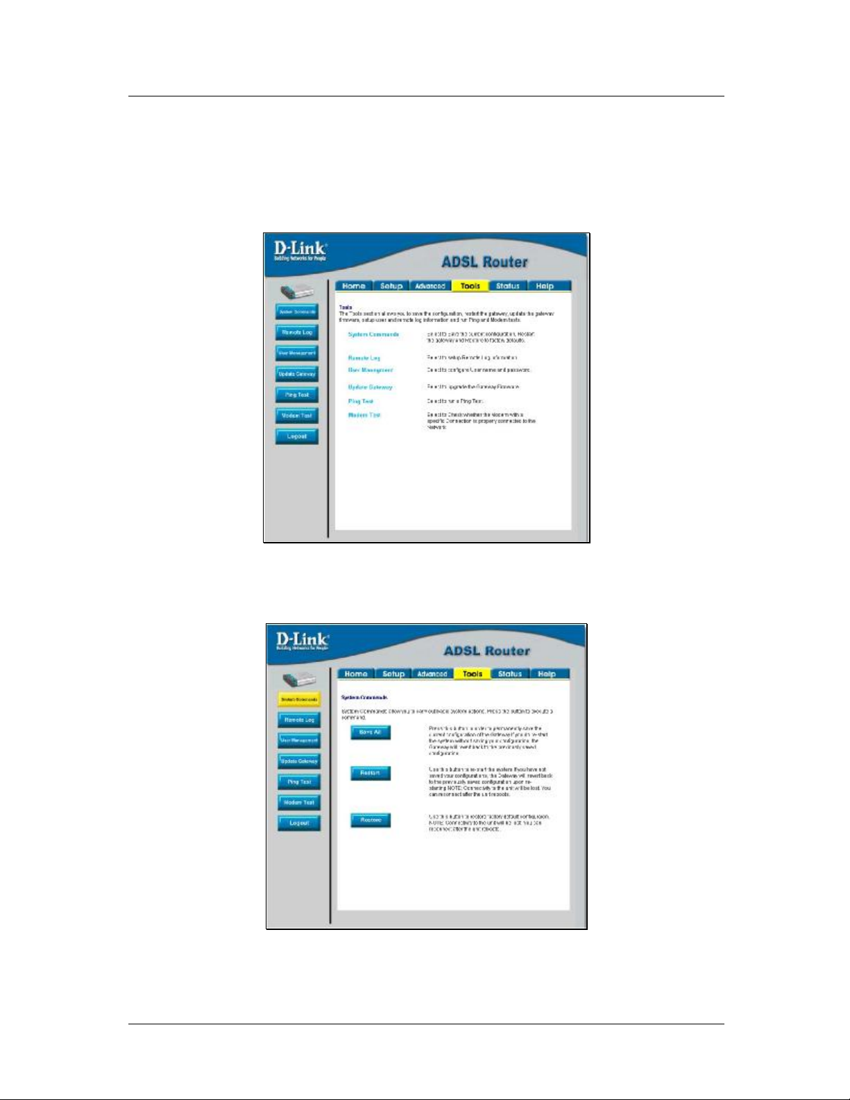
DSL-564T ADSL Router User’s Guide
Save Configuration Changes
Any changes made to the Router’ s configuration must be saved to non-volitile memory or they will be lost if the
Router is restarted or powered off. When you are finished making changes to the Router settings, follow the
instructions here to save the new settings.
Figure 3- 16. Router Tools Menus
Click on the Tools tab to access the System Commands menu link - then click the System Commands link to
see the menu pictured below.
Figure 3- 17. Available System Commands
To save the new settings, click on the Save All button. It will take a second or two to perform the save. After the
save is completed, a message appears in a new menu (see below).
33
Page 46

DSL-564T ADSL Router User’s Guide
Figure 3- 18. Changes permanently saved message
To return to the System Commands menu you can click the Back button in the new menu or use the back fuction
of the web browser.
34
Page 47

DSL-564T ADSL Router User’s Guide
4
Advanced Router Management
Click the Advanced tab to access menus used to configure UPnP, Port Forwarding, Access Control,
Advanced Security (including NAT, Firewall and DMZ setup), LAN Clients, Bridge Filters, Multicast passthrough, Static Routing and Dynamic Routing (RIP setup).
Figure 4-1. Advanced setup main menu
35
Page 48

DSL-564T ADSL Router User’s Guide
UPnP
UPnP supports zero-configuration networking and automatic discovery for many types of networked devices.
When enabled, it allows other devices that support UPnP to dynamically join a network, obtain an IP address,
convey its capabilities, and learn about the presence and capabilities of other devices. DHCP and DNS service
can also be used if available on the network. UPnP also allows supported devices to leave a network
automatically without adverse effects to the device or other devices on the network.
UPnP can be supported by diverse networking media including Ethernet, Firewall, phoneline and powerline
networking.
Figure 4-2. Advanced – UPnP window
To enable UPnP for any available connection, click to check the Enable UPnP selection box, select the
connection or connections on which you will enable UPnP listed under Available Connections and click the
Apply button.
36
Page 49

DSL-564T ADSL Router User’s Guide
LAN Clients
The LAN Clients menu is used when establishing Port Forwarding, Access Control and Advanced Security rules
for IP addresses on the LAN. This menu can be accessed directly by clicking on the LAN Clients button or
hyperlink in the Advanced setup menu. You can also click on the New IP button located in the Port Forwarding,
Access Control and Advanced Security menus to access this menu. In order to use these advanced features it is
necessary to have IP addresses available for configuration. If there are no IP addresses listed in the LAN Clients
menu, it will not be possible to configure Port Forwarding, Access Control and Advanced Security.
Use the LAN Clients menus to add or delete static IP addresses for the advanced functions mentioned above, or
to Reserve a Dynamically assigned IP address for an advanced function. Dynamically assigned IP addresses will
only be listed if DHCP is enabled on the Router.
Figure 4-3. LAN Clients Setup
To add a static IP address to the list of available IP addresses, type an IP address that falls within the range a
available IP addresses and click on the
10.0.0.1 to 10.255.255.254. Any addresses added will appear in the list of Static Addresses available for
advanced configuration. These addresses can then be used in the other Port Forwarding, Access Control and
Advanced Security menus.
To delete an IP address from the list of Static Addresses, click the Delete box for the address or addresses you
want to eliminate and click on the Apply button.
Dynamically assigned IP addresses may be reserved so that the LAN IP address for the device does not expire.
This will create a permanent entry for the device in the ARP table and in effect, it becomes a static IP address.
Click to check the Reserve box for the address or addresses you want to reserve and click the Apply button.
These reserved addresses will no longer be available for DHCP assignment and will be listed in the Static IP
Addresses table.
button. In the example above, available addresses range from
Add
37
Page 50

DSL-564T ADSL Router User’s Guide
Port Forwarding
Port Forwarding allows specific functions to bypass NAT protection that would otherwise not allow them to
function. To use Port Forwarding, you must have specific client IP addresses available for configuration. Use the
LAN Clients menu to establish client IP addresses available for port forwarding.
Note
In order to use Port Forwarding, Firewall support must be enabled. See Enable/Disable
NAT and Firewall in the Advanced Security menu.
Figure 4-4. Advanced – Port Forwarding window
There are many different pre-configured rules available for specific functions such as Internet gaming, VPN,
streaming and interactive multi-media, standard TCP/IP protocols, reserved ports, p2p, network management
applications, and so on.
38
Page 51

DSL-564T ADSL Router User’s Guide
You may also create customized rules to manage TCP/UDP ports. The pre-configured rules include those listed
in the table here:
Category Available Rules
Games:
VPN
Audio/Video
Applications
Servers
User
To configure a new port-forwarding rule for any of the pre-configured rules, follow these steps:
1. Select the WAN connection you want to use for the new rule from the Choose a connection pull-down
menu.
Alien vs. Predator, Asheron’s Call, Dark Rein, Delta Force, Doom, Dune, DirectX
Games, EliteForce, EverQuest, Fighter Ace II, Half Life, Heretic II, Hexen II, Kali,
Motorhead, MSN Gaming Zone, Myth: The Fallen Lords, Need for Speed Porsche,
Need for Speed 3, Outlaws, Rainbow 6, Starcraft, Tiberian Sun, Ultima, Unreal
Tournament.
IPSec, PPTP,L2PT
Net2Phone, Netmeeting, QuickTime
VNC, Win2k Terminal, PC Anywhere, Netbios, RemoteAnything, Radmin, LapLink,
CorbonCopy, Gnutella.
Quake 2, Quake 3, Unreal, Web, FTP, Telnet, DNS, LDAP, NNTP, SMTp, POP 2,
POP3, IMAP, IRC, Lotus, Remote.
Use this to set up custom TCP/UDP port rules.
2. Select a LAN IP from the available client IP addresses listed in the pull-down menu; or, create a New
IP by clicking the button. This brings up the LAN Client menu (see above).
3. Select the Category of the rule you are creating. The Available Rules for the category appear listed.
4. Highlight to select the Available Rule you want to apply.
5. Click on the Add> button to place the rule in the Applied Rules list of port forwarding that are actively
applied to the client
The Available Rules can be applied to a single client IP address. That is, it is not possible to use an applied rule
for multiple IP addresses on the LAN.
39
Page 52

DSL-564T ADSL Router User’s Guide
The User category for port forwarding is used to set up customized port forwarding rules.
Figure 4- 5. Set up Custom Port Forwarding Rules
To set up custom TCP or UDP port forwarding rules, follow these steps:
1. Select the User category and click the Add button located below the Available Rules list. This will
change the menu to look like the example below.
40
Page 53

DSL-564T ADSL Router User’s Guide
Figure 4- 6. Port Forwarding User Rules Management
2. Type a Rule Name in the space provided.
3. Select the port Protocol from the pull-down menu - you may select TCP, UDP or both (TCP/UDP).
4. Configure a range of ports for forwarding. Type the lowest numbered port in the range in the Port Start
space. Type the highest numbered port in the Port End space. For a single port, just enter the same
number in both spaces.
5. Type a number for the Port Map in the space provided. This is the local port being forwarded to.
6. Click the
port forwarding rules.
button to create the new rule. The new rule will appear listed in the table of custom
Apply
41
Page 54

DSL-564T ADSL Router User’s Guide
Access Control
Access Control settings are used to block various services and protocols for specific client IP addresses. The
configuration process is similar setting up port forwarding, except access control will deny specific functions to
client IP addresses. There are pre-configured rules for specific functions that may be blocked or you can block
specific UDP or TCP ports. Access control operates for specific IP addresses across all WAN connections. If
you are using more than one WAN connection, a single set of access rules is maintained for each controlled IP
address that operates on all WAN connections.
Note
In order to use Port Access Control, Firewall support must be enabled. See
Enable/Disable NAT and Firewall in the Advanced Security menu.
Figure 4-7. Access Control menu
Remember, if the client IP address you want does not appear listed in the LAN IP pull-down menu, click on the
New IP button to go to the LAN Clients menu.
To block all traffic from the WAN port to a specific IP address, select the LAN IP address to block and click to
check the
WAN port to the specified client.
Remember to save the configuration changes.
Traffic Type __ Any
selection box, then click the
42
button. This will block all traffic from the
Apply
Page 55

DSL-564T ADSL Router User’s Guide
Access Control pre-configured rules are the same as for port forwarding:
Category Available Rules
Games:
Alien vs. Predator, Asheron’s Call, Dark Rein, Delta Force, Doom, Dune, DirectX
Games, EliteForce, EverQuest, Fighter Ace II, Half Life, Heretic II, Hexen II, Kali,
Motorhead, MSN Gaming Zone, Myth: The Fallen Lords, Need for Speed Porsche,
Need for Speed 3, Outlaws, Rainbow 6, Starcraft, Tiberian Sun, Ultima, Unreal
Tournament.
VPN
Audio/Video
Applications
IPSec, PPTP,L2PT
Net2Phone, Netmeeting, QuickTime
VNC, Win2k Terminal, PC Anywhere, Netbios, RemoteAnything, Radmin, LapLink,
CorbonCopy, Gnutella.
Servers
Quake 2, Quake 3, Unreal, Web, FTP, Telnet, DNS, LDAP, NNTP, SMTp, POP 2,
POP3, IMAP, IRC, Lotus, Remote.
User
Use this to set up custom TCP/UDP port rules.
To configure a new Access Control rule for any of the pre-configured rules, follow these steps:
1. Select a LAN IP from the available client IP addresses listed in the pull-down menu; or, create a New
IP by clicking the button. This brings up the LAN Client menu (see above).
2. Select the Category of the rule you are creating. The Available Rules for the category appear listed.
3. Highlight to select the Available Rule you want to apply.
4. Click on the Add> button to place the rule in the Applied Rules list of port forwarding that are actively
applied to the client
The Available Rules can be applied to a single client IP address. That is, it is not possible to use an applied rule
for multiple IP addresses on the LAN.
To set up custom TCP or UDP access control rules, follow these steps:
1. Select the User category and click the Add button located below the Available Rules list.
2. In the new menu that appears, type a Rule Name in the space provided.
3. Select the port Protocol from the pull-down menu - you may select TCP, UDP or both (TCP/UDP).
4. Configure a range of ports for forwarding. Type the lowest numbered port in the range in the Port Start
space. Type the highest numbered port in the Port End space. For a single port, just enter the same
number in both spaces.
5. Type a number for the Port Map in the space provided. This is the local port being forwarded to.
6. Click the Apply button to create the new rule. The new rule will appear listed in the table of custom
port control rules.
43
Page 56

DSL-564T ADSL Router User’s Guide
Advanced Security
Use the Advanced Security features of the Router to globally enable or disable NAT and Firewall protection for
any WAN connection, enable or disable DMZ IP addresses, enable or disable remote Telnet or web management
from specified IP addresses, and enable/disable ICMP ping packets from the WAN.
Figure 4-8. Advanced Security menu
Follow the instructions below to set up the Advanced Security features. To enable ICMP Ping packets from the
WAN, click to check the Allow Incoming ICMP Ping selection box and click the Apply button. The ICMP
(Internet Control Message Protocol) Ping packet is used to test connectivity of IP devices. Keep in mind that
when this is enabled, the Router may be vulnerable to denial of service type attacks.
Enable/Disable NAT and Firewall
NAT and basic Firewall protection can be enabled or disabled for any WAN connection. These may also be
enabled or disabled when configuring the WAN connection for any connection type except Bridge connections.
By default, they are enabled for WAN connections (except Bridge connections) when they are first set up.
Firewall protection includes the previously discussed Port Forwarding and Access Control. Therefore, this must
be enabled to use these features.
To enable NAT and Firewall protection for any WAN connection including Bridge type connections, check the
Enable NAT and Firewall Services selection box and click the Apply button. Be sure to save the changes in
the System Commands menu or the settings will be lost.
To disable NAT and Firewall Services, deselect it and click the Apply button. Be aware that this remove basic
security and expose your LAN to potentially malicious agents form the WAN.
Remember to save the configuration changes.
44
Page 57

DSL-564T ADSL Router User’s Guide
DMZ IP Address
A DMZ address is used for a device that is not given basic protection of NAT and Firewall services. You may
select an IP address from the pull-down menu or create a New IP by pressing the button. This brings up the LAN
Clients menu in which you may create a static client IP or reserve a dynamically assigned IP address for DMZ
designation.
Setup Remote Management
Telnet and web management through the WAN port can be enabled for specified IP addresses. To enable remote
management, click to check the selection box for
net mask of a trusted host.
Remote Telnet
or
Remote Web
and type in an IP address and
Bridge Filters
Bridge filters are used to block or allow various types of packets through the WAN interface. This may be done
for security or to improve network efficiency. The rules are configured for individual devices based on MAC
address. Filter rules can be set up for source, destination or both. You can set up filter rules and disable the entire
set of rules without loosing the rules that have been configured.
Figure 4-9. Bridge Filters menu
To add a bridge filter rule, check Enable Bridge Filters, type in a Source MAC, a Destination MAC or both in
the entry fields, and click the Add button. To edit an existing rule, select the rule by clicking the Edit radio
button. The rule will appear in the entry fields above as it is currently configured. Make the desired changes and
click the Add button. To remove a bridge filter from the table in the bottom half of the window, click to select
the corresponding Delete box, and then click Apply. Remember to save the configuration changes.
The protocols that may be specifically allowed or denied to pass through the WAN interface are the following:
IPv4, RARP, PPPoE Discovery and PPPoE Session.
45
Page 58

DSL-564T ADSL Router User’s Guide
Multicast Pass-through
Multicast pass-through can be enabled or disabled for any WAN connection. When enabled it allows IGMP
packets to pass through the WAN interface. IGMP packets are used to control multicasts and discontinue
multicasts to individual IP addresses when they are no longer needed.
Figure 4-10. Multicast pass-through menu
To enable Multicast pass through for any WAN connection, select the connection and click the Enable IGMP
Multicast box to select the option, then click the Apply button. Remember to save the configuration changes.
46
Page 59

DSL-564T ADSL Router User’s Guide
Static Routing
Use Static Routing to specify a route used for data traffic within your Ethernet LAN or to route data on the WAN.
This is used to specify that all packets destined for a particular network or subnet use a predetermined gateway.
Figure 4-11. Static Routing menu
To add a static route, choose a connection from the pull-down menu and then enter a New Destination IP
address, subnet Mask, Gateway IP address and Metric value. Click Apply to enter the new static route in the
table below. The route becomes active immediately upon creation.
To remove a static route from the table in the bottom half of the window, choose to Delete it from the table and
click the Apply button. Remember to save the configuration changes.
47
Page 60

DSL-564T ADSL Router User’s Guide
Dynamic Routing
The Router supports RIP v1 and RIP v2 used to share routing tables with other Layer 3 routing devices. It also
supports use of password protection which requires password verification for RIP requests. Use the Dynamic
Routing menu to enable RIP and if desired to configure password protection.
Figure 4-12. Dynamic Routing (RIP) menu
To enable RIP v1, check Enable RIP, select RIP v1 Protocol, select the Direction (In, Out, or Both), and click
Apply. To enable RIP v2 or RIP v1 Compatible, select the appropriate Protocol and Direction and click Apply.
To use password protection for RIP v2 or RIP v1 Compatible protocols, check Enable Password, enter a
Password, and click Apply.
48
Page 61

DSL-564T ADSL Router User’s Guide
Multiple Virtual Connections
The Router can use up to eight simultaneous PVC connections. These additional connections occupy the same
bandwidth used for ADSL service. Additional PVC connections can be added to establish a private connection to
remote offices or maintain a server accessible through the WAN port. Provision for additional PVC profiles must
be done through the telephone company or telecommunications services company. The remote user must have
suitable ADSL equipment for a successful connection.
The New Connection menu is used to configure additional WAN connection that can operate simultaneously
with the other connections. PPPoE type WAN connections can be disconnected or connected as needed. NonPPPoE type connections must be deleted from the configuration settings if you want to disable them.
To set up additional virtual connections, follow the procedure described in Create a New Connection. Keep in
mind that each new connection must have a VPI/VCI value set that is unique to the Router. The numbers for
these values will be provided by your service provider.
PPPoE and PPPoA connections may be connected and disconnected with the Connect and Disconnect menu
buttons located in the connection settings menu.
The remaining connection types (Bridge, Static, DHCP and CLIP) connect upon saving the settings and
restarting the Router. These connections can be disconnected only if the connection set is deleted. To delete any
WAN connection set, click on the Delete button in the menu for the connection.
49
Page 62

DSL-564T ADSL Router User’s Guide
Tools and Utility Menus
The menus listed under the Tools tab are used for System Commands to save settings, restart and reset the
Router; to set up Remote Log information; for User Management; to update firmware and load saved
configuraiton files (in the Update Gateway menu); to perform a Ping test; and to test the DSL network
connectivity in the Modem Test menu.
Figure 4-13. Tools and utility menu links
Click the hyperlink or menu button to view the desired menu.
50
Page 63
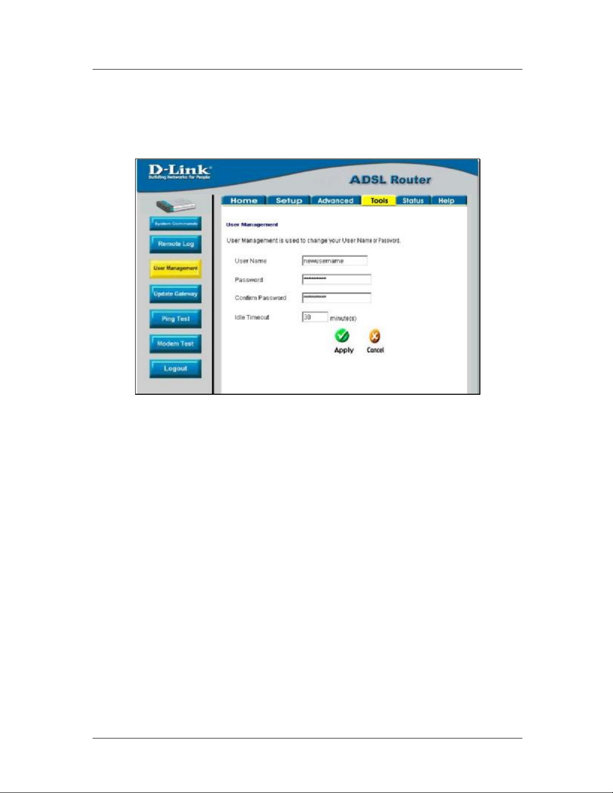
DSL-564T ADSL Router User’s Guide
User Management
It is a good idea to change the management user information used for the Router before or immediately after
establishing a link to the WAN.
Figure 4-14. User Management menu
To change the user name and password used for management access to the Router:
1. Type the current User Name in the entry field provided.
2. Type in the new Password in the entry field provided.
3. Type in the new password again in the Confirm Password field.
4. If desired, change the Idle Timeout value.
5. Click Apply.
51
Page 64

DSL-564T ADSL Router User’s Guide
System Commands
The System Commands are used to save settings to non-volatile memory, to reboot the Router and to restore
factory default settings to the Router.
Figure 4-15. Tools – System Commands menu
Click on the appropriate menu button to perform the following system tasks:
System Function Description
Save All
Restart
Restore
In order to save the configuration changes you have just made they must be
saved to the Router’s non-volatile RAM by clicking on the Save All button.
Click the
changes, the Router will revert to the previously saved configuration upon
rebooting the Router.
The DSL-564T can be reset to the default configuration for all settings using
the Restore option. This will also change the both the LAN and WAN IP
address of the device, so these will need to be reconfigured accordingly.
To perform a factory reset, click the Restore button. Since the IP settings will
return to their default, you will lose access to the Web Manager. To use the
Web Manager interface, the LAN IP address will need to be reconfigured.
Restart
button to restart the Router. If you have not saved your
52
Page 65

DSL-564T ADSL Router User’s Guide
Remote Log
Us the Remote Log menu to set up logging to servers or computers that are located outside the LAN or subnet of
the Router.
Figure 4-16. Remote Log menu
Select the Log Level from the pull-down menu. The levels available are: Alert, Critical, Debug, Error, Info,
Notice, Panic and Warning. Type in the IP address of a receiver for the log message in the
field and click on the Add button. Log message receivers that are added appear listed in the Select a logging
destination pull-down menu. These may be used at any time for other types of log messages. To remove a log
message receiver from the list, select it and click on the Remove button. Click the Apply button when you have
configured the log message receivers. Remember to save the settings to non-volatile memory.
Add an IP
Address
53
Page 66

DSL-564T ADSL Router User’s Guide
Update Gateway
Use the Update Gateway feature to load the latest firmware for the device. You can obtain the latest version of
the DSL-564T firmware by logging onto the D-Link web site at www.dlink.com. Save the latest firmware
version to a file on your computer or an accessible TFTP server.
Figure 4-17. Tools – Update Gateway window
To upgrade firmware, type in the name and path of the file in the Select a Firmware image file space or click on
the Browse button to search for the file. Click the Update Gateway button to begin copying the file. The file
will load and restart automatically.
Use the Configuration – Backup & Restore features to store current settings to a file on your computer or to load
previously saved configuration files on the device.
To save the current settings to a configuration file on your computer, type in the full name and path in the Select
a Configuration file space or click on the Browse button to search for the file. Click the Back Up button to
initiate this action.
To load a saved configuration file from the computer, type in the full name and path in the Select a
Configuration file space or click on the Browse button to search for the file. Click the Restore button to initiate
this action.
54
Page 67

DSL-564T ADSL Router User’s Guide
Ping Test
The Ping Test menu allows you to ping any IP address from the Router to test connectivity to the address.
Figure 4-18. Tools – Ping Test window
To Ping a device, first enter the IP address of the device that you wish to Ping into the first field, the Packet Size
(in bytes) in the second field, and finally, enter the number of times you wish the Ping function to attempt a
connection to the desired device into the third field. Click Test to start the Ping mechanism. The results of the
Ping will be shown in the result box in the bottom half of the window.
55
Page 68

DSL-564T ADSL Router User’s Guide
Modem Test
The Modem Test menu is used for trouble shooting connection problems on the WAN interface. You can test for
connectivity on the service provider’ s network for any WAN connection. Test for F5 or F4 connection on the
near segment or end-to-end.
Figure 4-19. Tools – Modem Test window
To test your modem, select a Connection, choose a Test Type, and click Test.
56
Page 69

DSL-564T ADSL Router User’s Guide
Status Menus
Use the Status windows to display various performance data about the Router
Figure 4-20. Status display links
Click the hyperlink or menu button for the desired Status window.
57
Page 70

Network Statistics
DSL-564T ADSL Router User’s Guide
Figure 4-21. Network Statistics window
Choose the desired interface at the top of the window and then click Refresh to view Ethernet network statistics.
58
Page 71

Connection Status
DSL-564T ADSL Router User’s Guide
Figure 4-22. Connection Status window
Click Refresh to view connection status information.
DHCP Clients
This window displays the status of all current DHCP clients.
Figure 4-23. DHCP Clients window
59
Page 72

DSL-564T ADSL Router User’s Guide
Modem Status
This window displays DSL statistics and various modem status data.
Figure 4-24. Modem Status window
Product Information
This window displays product information including hardware and firmware versions.
Figure 4-25. Product Information window
60
Page 73

DSL-564T ADSL Router User’s Guide
System Log
The system log displays chronological event log data.
Figure 4-26. System Log window
Click Refresh to get the most current system log information.
Help Menu
Help menu links provide more information for configuring various Router functions.
Figure 4-27. Opening Help window
61
Page 74

DSL-564T ADSL Router User’s Guide
Technical Specifications
GENERAL
A
Standards:
Protocols:
Data Transfer
Rate:
Media Interface:
ITU G.992.1 (G.dmt) Annex B
ITU G.992.2 (G.lite) AnnexB
ITU G.994.1 (G.Hs)
ITU-T Rec. I.361
ITU-T Rec. I.610
IEEE 802.3
IEEE 802.3u
IEEE 802.1d
RFC 791 (IP Routing)
RFC 792 (UDP)
RFC 826 (ARP)
RFC 1058 (RIP 1)
RFC 1389 (RIP 2)
RFC 1213 compliant
RFC 1483 (Bridged Ethernet)
TCP/IP
UDP
RIP-1
RIP-2
IGMP
G.dmt full rate: Downstream up to 8 Mbps
Upstream up to 640 Kbps
G.lite: Downstream up to 1.5 Mbps
Upstream up to 512 Kbps
RJ-11 port ADSL telephone line connection
RJ-45 port for 10/100BASET Ethernet connection
RFC 1577 (IP over ATM)
RFC 1661 (PPP)
RFC 1994 (CHAP)
RFC 1334 (PAP)
RFC 2364 (PPP over ATM)
RFC 1631 (NAT)
RFC 1877 (Automatic IP assignment)
RFC 2516 (PPP over Ethernet)
Supports RFC 2131 and RFC 2132 (DHCP)
Compatible with all T1.413 issue 2 (full rate
DMT over analog POTS), and CO DSLAM
equipment
Supports ATM Forum UNI V3.1 PVC
DHCP
BOOTP
ARP
AAL5
62
Page 75

DSL-564T ADSL Router User’s Guide
Physical and Environmental
DC Inputs:
Power Adapter:
Power
Consumption:
Operating
Temperature:
Humidity:
Dimensions:
Weight:
EMI:
Safety:
Reliability:
Input: 100V ~ 240V AC 50 ~ 60Hz
Output: 12V AC, 1.2A
12 Watts (max)
0° to 40° C (32° - 104° F)
5 to 95% (non-condensing)
180 x 141 x 30 mm
332 g
CE Class B, FCC Class B (Part 15)
CSA International
Mean Time Between Failure (MTBF) min. 4 years
63
Page 76

DSL-564T ADSL Router User’s Guide
B
IP Address Setup
The DSL-564T is designed to provide network administrators maximum flexibility for IP addressing on the
Ethernet LAN. The easiest IP setup choice in most cases is to let the Router do it using DHCP, which is enabled
by default. This appendix briefly describes various options including DHCP, used for IP setup on a LAN. If you
are new to IP networking, the next appendix provides some background information on basic IP concepts.
Assigning Network IP Addresses
The IP address settings, which include the IP address, subnet mask and gateway IP address are the first and most
important internal network settings that need to be configured. The Router is assigned a default LAN IP address
and subnet mask. If you do not have a preexisting IP network and are setting one up now, using the factory
default IP address settings can greatly ease the setup process. If you already have a preexisting IP network, you
can adjust the IP settings for the Router to fit within your existing scheme.
Using the Default IP Address
The Router is shipped with a preset default IP address setting of 192.168.1.1 for the LAN port. There are two
ways to use this default IP address, you can manually assign an IP address and subnet mask for each PC on the
LAN or you can instruct the Router to automatically assign them using DHCP. The simplest method is to use
DHCP. The DHCP function is active by default.
Manual IP Address Assignment
Manually configuring IP settings for the LAN means you must manually set an IP address, subnet mask and IP
address of the default gateway (the Router’s IP address) on each networked computer. The example listed below
describes IP configuration for computers running Windows 95 or Windows 98. Regardless of what operating
system is used on each workstation, the three network IP settings must be defined so the network interface used
by each workstation can be identified by the Router, and vice versa. For detailed information about configuring
your workstations IP settings, consult the user’ s guide included with the operating system or the network
interface card (NIC).
1. In Windows 95/98, click on the Start button, go to Settings and choose Control Panel.
2. In the window that opens, double-click on the Network icon.
3. Under the Configuration tab, select the TCP/IP component and click Properties.
4. Choose the Specify an IP address option and edit the address settings accordingly. Consult the table below
for IP settings on a Class C network.
Using Default IP without DHCP
Host IP Address Subnet Mask Gateway IP
Router
Computer #1
Computer #2
Computer #3
192.168.1.1 255.255.255.0
192.168.1.2 255.255.255.0 192.168.1.1
192.168.1.3 255.255.255.0 192.168.1.1
192.168.1.4 255.255.255.0 192.168.1.1
IP Setup - Example #1
Please note that when using the default IP address as in the above example, the first three numbers in the IP
address must always be the same with only the fourth number changing. The first three numbers define the
network IP address (all machines must belong to the same IP network), while the last number denotes the host IP
64
Page 77

DSL-564T ADSL Router User’s Guide
address (each computer must have a unique address to distinguish it on the network). The IP address scheme
used in Example #1 can be used for any LAN that requires up to 253 separate IP addresses (excluding the
Router). Notice that the subnet mask is the same for all machines and the default gateway address is the LAN IP
address of the Router.
It is a good idea to make a note of each device’ s IP address for reference during troubleshooting or when adding
new stations or devices.
Using DHCP
The second way to use the default settings is to allow the Router to automatically assign IP settings for
workstation using DHCP. To do this, simply make sure your computers’ IP addresses are set to 0.0.0.0 (under
Windows, choose the option Obtain an IP address automatically in the TCP/IP network component described
above). When the computers are restarted, their IP settings will automatically be assigned by the Router. The
Router is set by default to use DHCP. See the discussion in Chapter 5 for information on how to use configure
the Router for DHCP.
Changing the IP Address of the Router
When planning your LAN IP address setup, you may use any scheme allowed by rules that govern IP assignment.
It may be more convenient or easier to remember an IP scheme that use a different address for the Router. Or
you may be installing the Router on a network that has already established the IP settings. Changing the IP
address is a simple matter and can be done using the web manager (see LAN IP Address in Chapter 5). If you are
incorporating the Router into a LAN with an existing IP structure, be sure to disable the DHCP function. Also,
consider the effects of the NAT function which is enable by default.
An IP addressing scheme commonly used for Ethernet LANs establishes 10.0.0.1 as the base address for the
network. Using Example #2 below, the Router is assigned the base address 10.0.0.1 and the remaining addresses
are assigned manually or using DHCP.
Alternative IP Assignment
Host IP Address Subnet Mask Gateway IP
Router
Computer #1
Computer #2
Computer #3
These two examples are only examples you can use to help you get started. If you are interested in more
advanced information on how to use IP addressing on a LAN there are numerous resources freely available on
the Internet. There are also many books and chapters of books on the subject of IP address assignment, IP
networking and the TCP/IP protocol suite.
10.0.0.1 255.255.255.0 10.0.0.254
10.0.0.2 255.255.255.0 10.0.0.254
10.0.0.3 255.255.255.0 10.0.0.254
10.0.0.4 255.255.255.0 10.0.0.254
IP Setup - Example #2
65
Page 78

DSL-564T ADSL Router User’s Guide
C
IP Concepts
This appendix describes some basic IP concepts, the TCP/IP addressing scheme and show how to assign IP
Addresses.
When setting up the Router, you must make sure it has a valid IP address. Even if you will not use the WAN port
(ADSL port), you should, at the very least, make sure the Ethernet LAN port is assigned a valid IP address. This
is required for telnet, in-band SNMP management, and related functions such as “trap” handling and TFTP
firmware download.
IP Addresses
The Internet Protocol (IP) was designed for routing data between network sites all over the world, and was later
adapted for routing data between networks within any site (often referred to as “subnetworks” or “subnets”). IP
includes a system by which a unique number can be assigned to each of the millions of networks and each of the
computers on those networks. Such a number is called an IP address.
To make IP addresses easy to understand, the originators of IP adopted a system of representation called “dotted
decimal” or “dotted quad” notation. Below are examples of IP addresses written in this format:
201.202.203.204 189.21.241.56 125.87.0.1
Each of the four values in an IP address is the ordinary decimal (base 10) representation of a value that a
computer can handle using eight “bits” (binary digits — 1s and 0s). The dots are simply convenient visual
separators.
Zeros are often used as placeholders in dotted decimal notation; 189.21.241.56 can therefore also appear as
189.021.241.056.
IP networks are divided into three classes on the basis of size. A full IP address contains a network portion and a
“host” (device) portion. The network and host portions of the address are different lengths for different classes of
networks, as shown in the table below.
66
Page 79
DSL-564T ADSL Router User’s Guide
Networks attached to the Internet are assigned class types that determine the maximum number of possible hosts
per network. The previous figure illustrates how the net and host portions of the IP address differ among the
three classes. Class A is assigned to networks that have more than 65,535 hosts; Class B is for networks that
have 256 to 65534 hosts; Class C is for networks with less than 256 hosts.
IP Network Classes
Class
Note: All network addresses outside of these ranges (Class D and E) are either reserved or set aside for
When an IP address's host portion contains only zero(s), the address identifies a network and not a host. No
physical device may be given such an address.
The network portion must start with a value from 1 to 126 or from 128 to 223. Any other value(s) in the network
portion may be from 0 to 255, except that in class B the network addresses 128.0.0.0 and 191.255.0.0 are
reserved, and in class C the network addresses 192.0.0.0 and 223.255.255.0 are reserved.
The value(s) in the host portion of a physical device's IP address can be in the range of 0 through 255 as long as
this portion is not all-0 or all-255. Values outside the range of 0 to 255 can never appear in an IP address (0 to
255 is the full range of integer values that can be expressed with eight bits).
The network portion must be the same for all the IP devices on a discrete physical network (a single Ethernet
LAN, for example, or a WAN link). The host portion must be different for each IP device — or, to be more
precise, each IP-capable port or interface — connected directly to that network.
The network portion of an IP address will be referred to in this manual as a network number; the host portion
will be referred to as a host number.
Maximum Number
of Networks in
Class
A
126 1(.0.0.0) to 126(.0.0.0) 16,777,214
B
16,382 128.1(.0.0) to 191.254(.0.0) 65,534
C 2,097,150 192.0.1(.0) to 223.255.254(.0) 254
experimental networks or multicasting.
Network Addresses (Host
Portion in Parenthesis)
Maximum Number of
Hosts per Network
To connect to the Internet or to any private IP network that uses an Internet-assigned network number, you must
obtain a registered IP network number from an Internet-authorized network information center. In many
countries you must apply through a government agency, however they can usually be obtained from your
Internet Service Provider (ISP).
If your organization's networks are, and will always remain, a closed system with no connection to the Internet
or to any other IP network, you can choose your own network numbers as long as they conform to the above
rules.
If your networks are isolated from the Internet, e.g. only between your two branch offices, you can assign any IP
Addresses to hosts without problems. However, the Internet Assigned Numbers Authority (IANA) has reserved
the following three blocks of IP Addresses specifically for private (stub) networks:
Class Beginning Address Ending Address
A 10.0.0.0 10.255.255.255
B 172.16.0.0 172.31.255.255
C 192.168.0.0 192.168.255.255
It is recommended that you choose private network IP Addresses from the above list. For more information on
address assignment, refer to RFC 1597, Address Allocation for Private Internets and RFC 1466, Guidelines for
Management of IP Address Space.
67
Page 80

DSL-564T ADSL Router User’s Guide
Subnet Mask
In the absence of subnetworks, standard TCP/IP addressing may be used by specifying subnet masks as shown
below.
IP Class Subnet Mask
Class A 255.0.0.0
Class B 255.255.0.0
Class C 255.255.255.0
Subnet mask settings other than those listed above add significance to the interpretation of bits in the IP address.
The bits of the subnet mask correspond directly to the bits of the IP address. Any bit an a subnet mask that is to
correspond to a net ID bit in the IP address must be set to 1.
68
Page 81

DSL-564T ADSL Router User’s Guide
D
Microfilters and Splitters
Most ADSL clients will be required to install a simple device that prevents the ADSL line from interfering with
regular telephone services. These devices are commonly referred to as microfilters or sometimes called
(inaccurately) line splitters. They are easy to install and use standard telephone connectors and cable.
Some ADSL service providers will send a telecommunications technician to modify the telephone line, usually
at the point where the telephone line enters the building. If a technician has divided or split your telephone line
into two separate lines - one for regular telephone service and the other for ADSL – then you do not need to use
any type of filter device. Follow the instructions given to you by your ADSL service provider about where and
how you should connect the Modem to the ADSL line.
Microfilters
Unless you are instructed to use a “line splitter” (see below), it will be necessary to install a microfilter (low pass
filter) device for each telephone or telephone device (answering machines, Faxes etc.) that share the line with the
ADSL service. Microfilters are easy-to-install, in-line devices, which attach to the telephone cable between the
telephone and wall jack. Microfilters that install behind the wall plate are also available. A typical in-line
microfilter installation is shown in the diagram below.
Microfilter Installation
Important: Do not install the microfilter between the Modem and the telephone jack. Microfilters are only
intended for use with regular telephones, Fax machines and other regular telephone devices.
69
Page 82

DSL-564T ADSL Router User’s Guide
Line Splitter
If you are instructed to use a “line splitter”, you must install the device between the Modem and the phone jack.
Use standard telephone cable with standard RJ-11 connectors. The splitter has three RJ-11 ports used to connect
to the wall jack, the Modem and if desired, a telephone or telephone device. The connection ports are typically
labeled as follows:
Line - This port connects to the wall jack.
ADSL – This port connects to the Modem.
Phone – This port connects to a telephone or other telephone device.
The diagram below illustrates the proper use of the splitter.
Line Splitter Installation
70
Page 83

Offices
Australia D-Link Australasia
1 Giffnock Avenue, North Ryde, NSW 2113, Sydney, Australia
TEL: 61-2-8899-1800 FAX: 61-2-8899-1868
URL: www.dlink.com.au
Belgium D-Link Belgium
Rue des Colonies 11, B-1000 Brussels, Belgium
TEL: 32 (0)2 517 7111 FAX: 32 (0)2 517 6500
URL: www.dlink-benelux.com
Brazil D-Link Brasil Ltda.
Av das Nações Unidas, 11857, cj 132 – Brooklin Novo
São Paulo, Brasil 04578-000
TEL: (55 11) 5503-9320 FAX: (55 11) 5503-9321
URL: www.dlink.com.br
Canada D-Link Canada
2180 Winston Park Drive, Oakville,
Ontario, L6H 5W1 Canada
TEL: 1-905-829-5033 FAX: 1-905-829-5223
URL: www.dlink.ca
Chile D-Link South America (Sudamérica)
Isidora Goyenechea 2934 Oficina 702
Las Condes Fono 2323185, Santiago, Chile
TEL: 56-2-232-3185 FAX: 56-2-232-0923
URL: www.dlink.cl
China D-Link China
Room 507/508, Tower W1, The Towers, Oriental Plaza No. 1
East Chang An Ave., Dong Cheng District
Beijing, 100738, China
TEL: (86-010) 85182533 FAX: (86-010) 85182250
URL: www.dlink.com.cn
Denmark D-Link Denmark
Naverland 2, DK-2600 Glostrup, Denmark
TEL: 45-43-96-90-40 FAX: 45-43-42-43-47
URL: www.dlink.dk
Egypt D-Link Egypt
19 El-Shahed Helmy, El Masry, Al-Maza, Heliopolis, Cairo, Egypt
TEL: 202-41-44-295 FAX: 202-41-56-704
URL: www.dlink-me.com
Finland D-Link Finland
Pakkalankuja 7A, 3rd floor, 01510 Vantaa, Finland
TEL: 358-9-2707-5080 FAX: 358-9-2707-5081
URL: www.dlink.fi
France D-Link France
Le Florilege, No. 2, Allée de la Fresnerie,
78330 Fontenay le Fleury, France
TEL: 33-1-3023-8688 FAX: 33-1-3023-8689
URL: www.dlink-france.fr
Germany D-Link Central Europe (D-Link Deutschland GmbH)
Page 84

Schwalbacher Strasse 74, D-65760 Eschborn, Germany
TEL: 49-6196-77990 FAX: 49-6196-7799300
URL: www.dlink.de
India D-Link India
D-Link House, Kurla-Bandra Complex Rd., Off Cst Rd.,
Santacruz (East), Mumbai, 400 098 India
TEL: 91-022-652-6696/6578/6623
FAX: 91-022-652-8914/8476
URL: www.dlink.co.in & www.dlink-india.com
Israel D-Link Israel
11 Hamanofim Street, Ackerstein Towers, Regus Business Center
P.O.B. 2148, Hertzelia-Pituach 46120, Israel
TEL: 972-9-9715700 FAX: 972-9-9715601
URL: www.dlink.co.il
Italy D-Link Mediterraneo Srl/D-Link Italia
Via Nino Bonnet n. 6/B, 20154, Milano, Italy
TEL: 39-02-2900-0676 FAX: 39-02-2900-1723
URL: www.dlink.it
Netherlands D-Link Netherlands
Weena 290, 3012 NJ Rotterdam, The Netherlands
TEL: 31 (0)10 282 1445 FAX: 31 (0)10 282 1331
URL: www.dlink-benelux.com
Norway D-Link Norway
Karihaugveien 89, N-1086 Oslo
TEL: 47-23-89-71-89 FAX: 47-22-30-90-85
URL: www.dlink.no
Russia D-Link Russia
Grafsky per., 14, floor 6, Moscow 129626 Russia
TEL: 7 (095) 744-0099 FAX: 7 (095) 744-0099 #350
URL: www.dlink.ru
Singapore D-Link International
0 1 International Business Park, #03-12 The Synergy,
Singapore 609917
TEL: 65-6774-6233 FAX: 65-6774-6322
URL: www.dlink-intl.com
South Africa D-Link South Africa
Einstein Park II, Block B
102-106 Witch-Hazel Avenue
Highveld Technopark, Centurion, Gauteng, Republic of South Africa
TEL: 27-12-665-2165 FAX: 27-12-665-2186
URL: www.d-link.co.za
Spain
C/Sabino de Arana, 56 Bajos, 08028 Barcelona, Spain
TEL: 34 93 409 0770 FAX: 34 93 491 0795
URL: www.dlink.es
Sweden D-Link Sweden
P. O. Box 15036, S-167 15 Bromma, Sweden
TEL: 46-(0)8564-61900 FAX: 46-(0)8564-61901
URL: www.dlink.se
Taiwan D-Link Taiwan
D-Link Iberia
Page 85

2F, No. 119, Pao-chung Road, Hsin-tien, Taipei, Taiwan
TEL: 886-2-2910-2626 FAX: 886-2-2910-1515
URL: www.dlinktw.com.tw
Turkey D-Link Turkey
Regus Offices Beybi Giz Plaza, Ayazaga Mah. Meydan Sok. No. 28
Maslak 34396, Istanbul-Turkiye
TEL: 90-212-335-2553 FAX: 90-212-335-2500
URL: www.dlink.com.tr
U.A.E. D-Link Middle East
P.O. Box 500376, Office No. 103, Building 3
Dubai Internet City, Dubai, United Arab Emirates
TEL: 971-4-3916480 FAX: 971-4-3908881
URL: www.dlink-me.com
U.K. D-Link Europe (United Kingdom)
4
NW9 5AB United Kingdom
TEL: 44-020-8731-5555 FAX: 44-020-8731-5511
URL: www.dlink.co.uk
U.S.A. D-Link Systems, Inc.
17595 Mt. Herrmann, Fountain Valley, CA 92708, USA
TEL: 1-714-885-6000 FAX: 1-866-743-4905
URL: www.dlink.com
th
Floor, Merit House, Edgware Road, Colindale, London
Page 86

Registration Card
Print, type or use block letters.
Your name: Mr./Ms__________________________________________________________________________
Organization: ____________________________________________Dept.______________________________
Your title at organization:_____________________________________________________________________
Telephone:_________________________________________ Fax:___________________________________
Organization's full address:___________________________________________________________________
_________________________________________________________________________________________
Country:__________________________________________________________________________________
Date of purchase (Month/Day/Year):_______________________________________
Product
Model
(* Applies to adapters only)
Product was purchased from:
Reseller's name:____________________________________________________________________________
Telephone:_________________________________________ Fax:___________________________________
Reseller's full address:_______________________________________________________________________
_________________________________________________________________________________________
Answers to the following questions help us to support your product:
1. Where and how will the product primarily be used?
oHome oOffice oTravel oCompany Business oHome Business oPersonal Use
2. How many employees work at installation site?
o1 employee o2-9 o10-49 o50-99 o100-499 o500-999 o1000 or more
3. What network protocol(s) does your organization use ?
oXNS/IPX oTCP/IP oDECnet oOthers_______________________________________________________
4. What network operating system(s) does your organization use ?
oD-Link LANsmart oNovell NetWare oNetWare Lite oSCO Unix/Xenix oPC NFS o3Com 3+Open
oBanyan Vines oDECnet Pathwork oWindows NT oWindows NTAS oWindows '95
oOthers________________________________________________________________________________
5. What network management program does your organization use ?
o
D-View oHP OpenView/Windows oHP OpenView/Unix oSunNet Manager oNovell NMS
o
NetView 6000 oOthers___________________________________________________________________
6. What network medium/media does your organization use ?
oFiber-optics oThick coax Ethernet oThin coax Ethernet o10BASE-T UTP/STP
o100BASE-TX o100BASE-T4 o100VGAnyLAN oOthers_________________________________________
7. What applications are used on your network?
oDesktop publishing oSpreadsheet oWord processing oCAD/CAM
oDatabase management oAccounting oOthers_________________________________________________
8. What category best describes your company?
oAerospace oEngineering oEducation oFinance oHospital oLegal oInsurance/Real Estate oManufacturing
oRetail/Chainstore/Wholesale oGovernment oTransportation/Utilities/Communication oVAR
oSystem house/company oOther____________________________________________________________
9. Would you recommend your D-Link product to a friend?
oYes oNo oDon't know yet
10.Your comments on this product? _________________________________________________
__________________________________________________________________________________________
__________________________________________________________________________________________
__________________________________________________________________________________________
Product Serial No. * Product installed in type of
computer (e.g., Compaq 486)
* Product installed in computer serial No.
Page 87

 Loading...