

Page 1

DSA-6100
User Guide
Version DSA-6100-2.10 July, 2009
Page 2

Page 3

Copyright © 2009 D-Link Corporation
All rights reserved. Printed in Taiwan. September 2009. D-Link Corporation reserves the right to change, modify, and
revise this publication without notice.
Trademarks
Copyright 2009 D-Link Corporation. All rights reserved. D-Link, the D-Link logo, and DSA-6100 are trademarks of
D-Link Corporation. All other brand and product names are registered trademarks or trademarks of their respective
holders.
Statement of Conditions
In the interest of improving internal design, operational function, and/or reliability, D-Link Corporation reserves the right
to make any changes to products described in this document without notice. D-Link Corporation shall be indemnified
against any liability that may occur due to the use or application of the product(s) described herein.
Page 4

Page 5

Table of Contents
Chapter 1. Before You Start ....................................................................................................................................1
1.1 Audience ................................................................................................................................................1
1.2 Document Conventions.........................................................................................................................1
Chapter 2. Overview................................................................................................................................................2
2.1 Introduction of DSA-6100....................................................................................................................2
2.2 System Concept.....................................................................................................................................2
Chapter 3. Hardware Installation ..........................................................................................................................7
3.1 Panel Function Descriptions ................................................................................................................7
3.2 Package Contents..................................................................................................................................9
3.3 System Requirement.............................................................................................................................9
3.4 Installation Steps.................................................................................................................................10
Chapter 4. Web Interface Configuration .............................................................................................................11
4.1 System Configuration.........................................................................................................................14
4.1.1 Configuration Wizard (Also served as Quick Installation Guide)..................................................15
4.1.2 System Information.............................................................................................................................26
4.1.3 WAN1 Configuration..........................................................................................................................27
4.1.4 WAN2 & Failover................................................................................................................................30
4.1.5 LAN1 Configuration...........................................................................................................................31
4.1.6 LAN2 Configuration...........................................................................................................................35
4.2 Network Configuration ......................................................................................................................36
4.2.1 Network Address Translation.............................................................................................................37
4.2.2 Privilege List........................................................................................................................................40
4.2.3 Monitor IP List....................................................................................................................................43
4.2.4 Walled Garden List.............................................................................................................................45
4.2.5 Proxy Server Properties......................................................................................................................46
4.2.6 Dynamic DNS ......................................................................................................................................47
4.2.7 IP Mobility ...........................................................................................................................................48
4.3 AP Management.................................................................................................................................. 49
4.3.1 AP List..................................................................................................................................................50
4.3.2 AP Discovery........................................................................................................................................57
4.3.3 Manual Configuration ........................................................................................................................60
4.3.4 Template Settings ................................................................................................................................61
4.3.5 Firmware Management ......................................................................................................................76
4.3.6 AP Upgrade..........................................................................................................................................77
Page 6

4.4 User Authentication............................................................................................................................78
4.4.1 Authentication Configuration ............................................................................................................79
4.4.1.1 Local Server....................................................................................................................................80
4.4.1.2 POP3 Server....................................................................................................................................86
4.4.1.3 RADIUS Server ..............................................................................................................................87
4.4.1.4 LDAP Server...................................................................................................................................90
4.4.1.5 NT Domain Server..........................................................................................................................92
4.4.1.6 On Demand User ............................................................................................................................93
4.4.1.7 PMS User.........................................................................................................................................97
4.4.2 Policy Configuration .........................................................................................................................101
4.4.3 Black List Configuration..................................................................................................................109
4.4.4 Guest User Configuration.................................................................................................................113
4.4.5 Additional Configuration .................................................................................................................114
4.5 Status..................................................................................................................................................134
4.5.1 System Status.....................................................................................................................................135
4.5.2 Interface Status..................................................................................................................................137
4.5.3 Current Users ....................................................................................................................................139
4.5.4 Traffic History ...................................................................................................................................140
4.5.5 Notification Configuration ...............................................................................................................145
4.5.6 Online Report ....................................................................................................................................147
4.6 Tool.....................................................................................................................................................149
4.6.1 Change Password ..............................................................................................................................150
4.6.2 Backup/Restore Setting.....................................................................................................................154
4.6.3 Firmware Upgrade............................................................................................................................155
4.6.4 Ping Utility .........................................................................................................................................156
4.6.5 Restart................................................................................................................................................157
4.7 Help....................................................................................................................................................158
Appendix A. External Network Access .............................................................................................................159
Appendix B. Console Interface Configuration.................................................................................................162
Appendix C. Proxy Configuration.....................................................................................................................165
Appendix D. Certificate Setting for IE6 and IE7.............................................................................................172
Appendix E. VLAN Isolation.............................................................................................................................179
Appendix F. Session Limit and Session Log.....................................................................................................181
Page 7

Chapter 1. Before You Start
Chapter 1. Before You Start
1.1 Audience
This manual is intended for use by system integrators, field engineers and network administrators to help them set
up DSA-6100 Wireless Access Controller in their network environments. It contains step by step procedures and
pictures to guide users with basic network system knowledge to complete the installation.
1.2 Document Conventions
The following information provides the details of conventions used in this manual.
For cautionary statements or warning requiring special attention by readers, a text box with italic font will be used:
Warning: For security purposes, you should immediately change the administrator’s password.
When any of the button symbol shown below is selected, the following action will be executed accordingly:
Return to the homepage of this section.
Return to the previous page.
Apply all settings configured.
Clear all settings configured prior to applying.
Note: Screen captures and pictures used in this manual may be displaye d in part or in whole, and may vary or
differ slightly from the actual product, depending on versioning and menu accessed.
1
Page 8

DSA-6100 User Guide
Chapter 2. Overview
2.1 Introduction of DSA-6100
The DSA-6100 is a Network Access Controller designed for medium to large network environments to provide
network “manageability”, “efficiency” and a “friendly interface” suitable for campuses, libraries, gymnasiums,
small and middle enterprises, factories, hotspots and community hospitals.
2.2 System Concept
The DSA-6100 is built for the purpose of controlling all network data passing through its system. Users, under the
managed network, must be authenticated in order to access the network beyond the managed area. The
authentication mechanism at the user’s end is provided by the DSA-6100 server using SSL encryption to protect
the webpage. The DSA-6100 is responsible for the authentication, authorization, and management functions in the
system. User account information may be stored in the DSA-6100 database or in other specified external
authentication databases.
The process of authenticating the user’s identity is executed via the SSL encrypted webpage. The use of web
interface ensures the system is compatible to most desktop systems and palm computers. When a user
authentication is requested, the DSA-6100 server software checks the authentication database at the rear end to
confirm the user’s access right. The authentication database may be the local database of the DSA-6100 or any
external database that the DSA-6100 supports. If the user is not an authorized user, the DSA-6100 will refuse the
user’s request for access and block the user from accessing the network. If the user is an authorized user, the
DSA-6100 will grant the user appropriate access right so that the user can use the network. If the online user
remains idle without using the network for a time exceeding a predetermined idle time on the DSA-6100, or if the
online user logs out of the system, the DSA-6100 will exit the working stage of the user and terminate the user’s
access right of the network.
2
Page 9
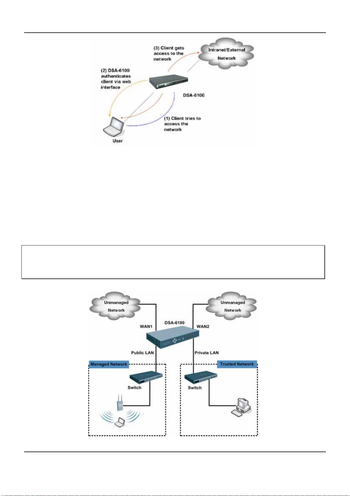
Chapter 2. Overview
The following picture provides a simple example of setting up middle to large enterprise network. The DSA-6100 is
set to control a part of the company’s intranet. The whole managed network includes cable network users, and
wireless network users. In the beginning, any user located at the managed network is unable to access the
network resource without permission. If the access right to the network beyond the managed area is required, an
Internet browser such as the Internet Explorer must be opened and a connection to any website must be
performed. When the browser attempts to connect to a website, the DSA-6100 will force the browser to redirect to
the user login webpage. The user must enter the username and password for authentication. After the identity is
authenticated successfully, the user will be granted proper access right as defined in the DSA-6100.
Attention: Public LAN
Authentication is required for the users to get access of the network. Private LAN is referred to as the LAN port
with the authentication function disabled.
is referred to as the LAN port with the authentication function enabled from where the
3
Page 10
DSA-6100 User Guide
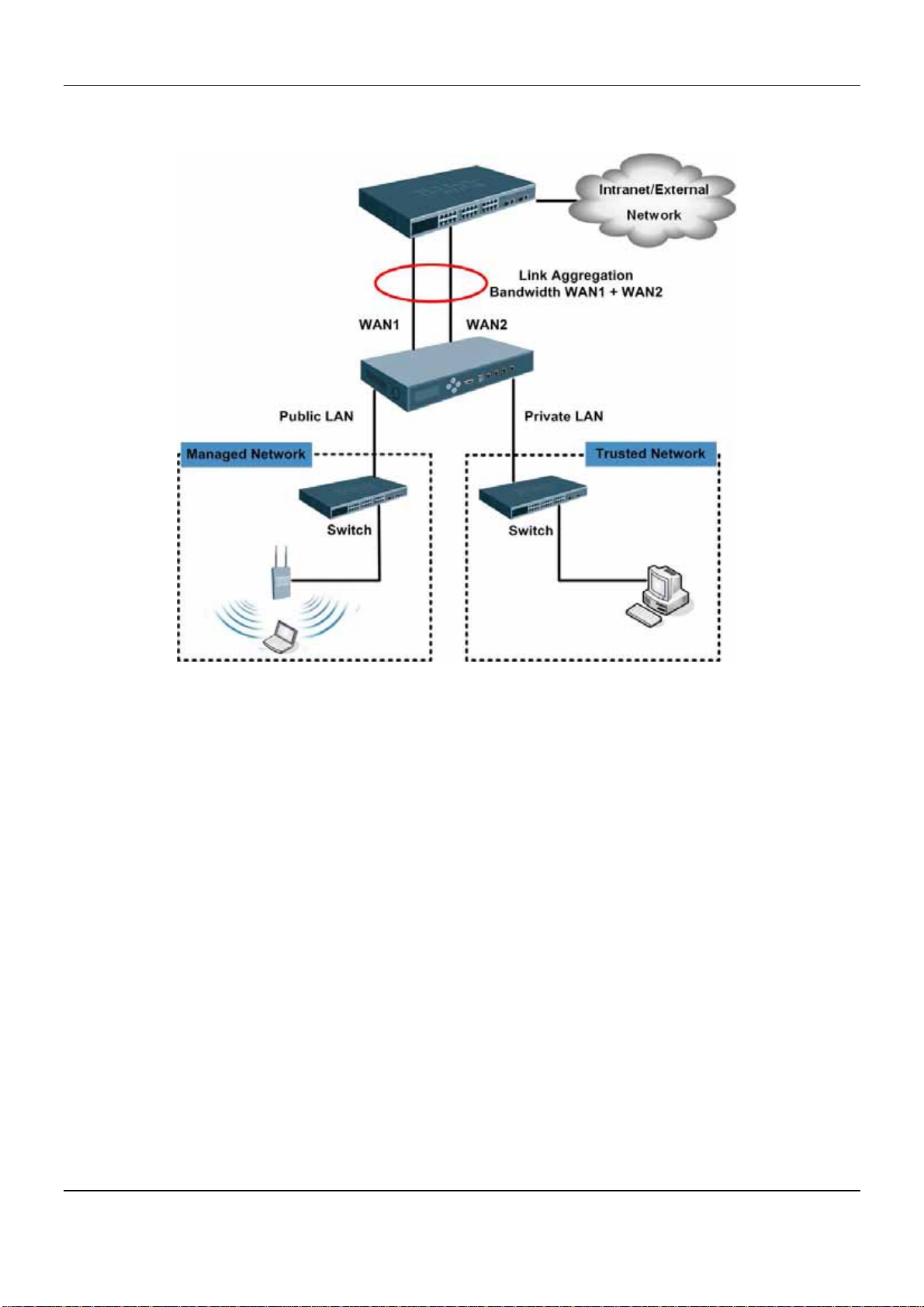
Another setup example is shown in the following diagram, where the administrator is able to increase the uplink
bandwidth capacity beyond the capacity of any single WAN port. This is done by the DSA-6100’s Bonding feature.
4
Page 11
Chapter 2. Overview
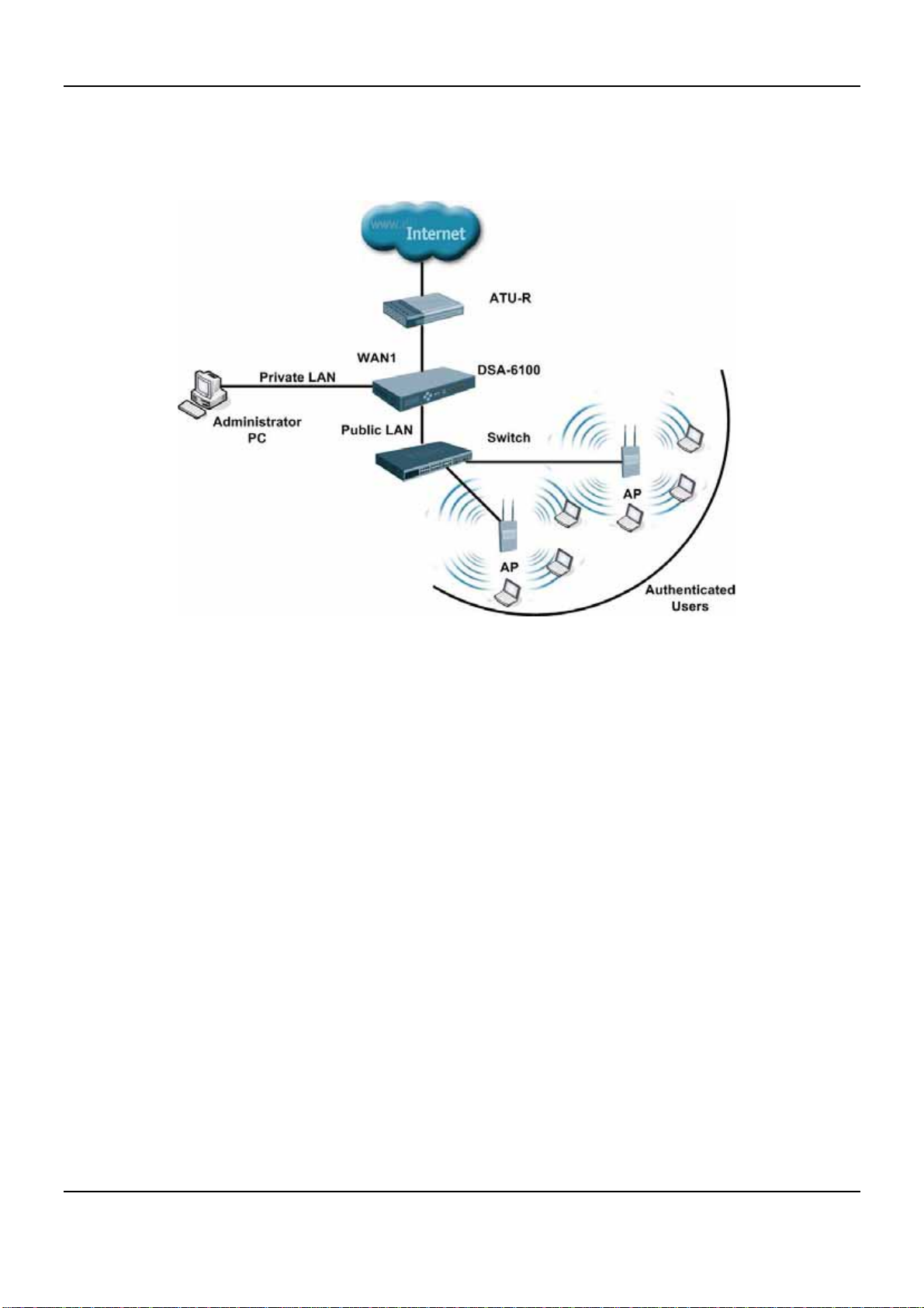
The DSA-6100 can be used as the gateway for Internet access, where an external connection can be established
for sharing, accounting, authentication and users management. This solution can be applied for environments such
as hotels, campus, hot spots and others. An example of the network topology is as follows:
5
Page 12
DSA-6100 User Guide
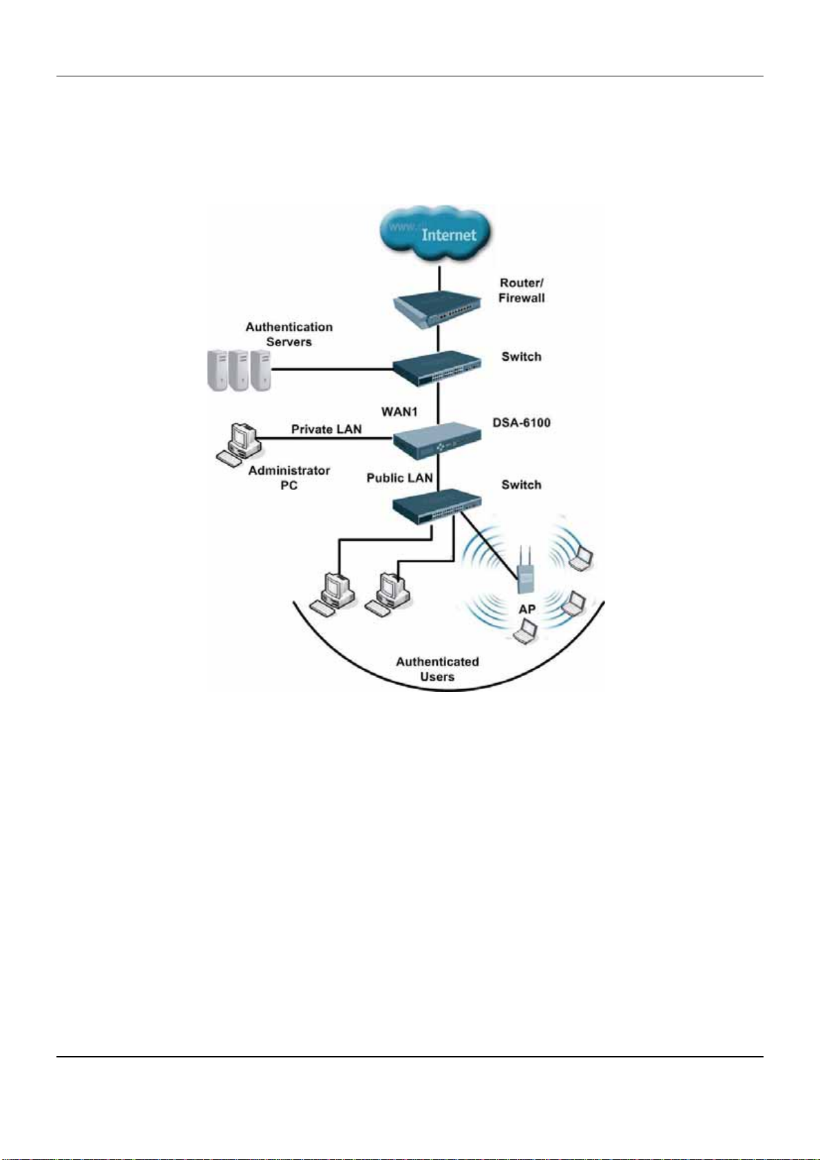
The DSA-6100 is able to use a Local Database or authentication servers (NT-Domain, POP3, LDAP and Radius)
to authenticate users. This type of solution is suitable for environments such as hotels, campus, hot spots,
enterprises and others.
6
Page 13
Chapter 3. Hardware Installation
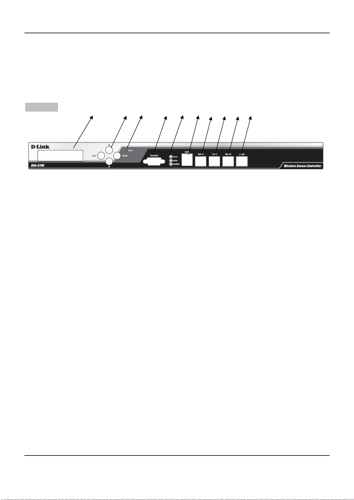
3.1 Panel Function Descriptions
Chapter 3. Hardware Installation
Front Panel
1. Reset 3. LED 5. Port: USB 7. Port: LAN1 / LAN2
2. Select / Execute 4. LCD 6. Port: Console 8. Port: WAN1 / WAN2
1. Reset
Press and hold the Reset Button for 5 seconds to restart the DSA-6100.
Press and hold the Reset Button for more than 10 seconds to restart the DSA-6100 in default
configuration.
2. Select / Execute
4 2 1 6 3 5 8 7 8 7
Esc: Cancel selected function
Enter: Execute selected function in menu
Arro w Up: Navigate upward to select required function in menu
Arro w Down: Navigate downward to select required function in menu
3. LED
Power: ON indicates that power is on and OFF indicates that power is off.
Status: OFF indicates BIOS is running, BLINKING indicates the OS is running, and ON indicates
system is ready.
Hard Disk: Reserved for future usage.
Port Speed:
¾ Upper left indicator: OFF indicates no connection, ON (orange color) indicates connection and
BLINKING indicates transmitting data.
¾ Upper right indicator: OFF indicates 10Mbps connection, ON (green color) indicates 100Mbps
connection and ON (orange color) indicates 1000Mbps connection.
7
Page 14

DSA-6100 User Guide
4. LCD: Shows the information about the System and Network listed below:
System Info:
H.W. Status (CPU Temperature)
¾
Utilization (CPU (%) and Memory (%))
¾
System Time
¾
Boot-up Time
¾
Firmware
¾
Network Info: WAN 1 / WAN 2 / LAN 1 / LAN 2
¾ Setting (IP Address and Netmask)
¾ Loading (In/Out Pkts/s and In/Out Bytes/s)
¾ Status (Connected or Disconnected)
5. USB Port: Reserved for future use.
6. Console Port: The system can be configured via HyperTerminal. For example, if you need to set the
Administrator’s Password, you can connect a PC to this port as a Console Serial Port via a terminal
connection program (the terminal’s configuration must be 9600bps, 8, N, 1, flow control - none) to change
the Administrator’s Password.
7. LAN1 / LAN2 Ports: The two LAN ports can be independently configured and set to disallow users to
access Internet before authentication. Administrators can therefore choose to force authentication on
users connected to these ports.
8. WAN1 / WAN2 Ports: The two WAN ports are connected to a network which is not managed by the
DSA-6100, and this port can be used to connect to the ATU-Router of an ADSL, or the port of a Cable
Modem, or the Switch or Hub on the LAN of an organization.
8
Page 15
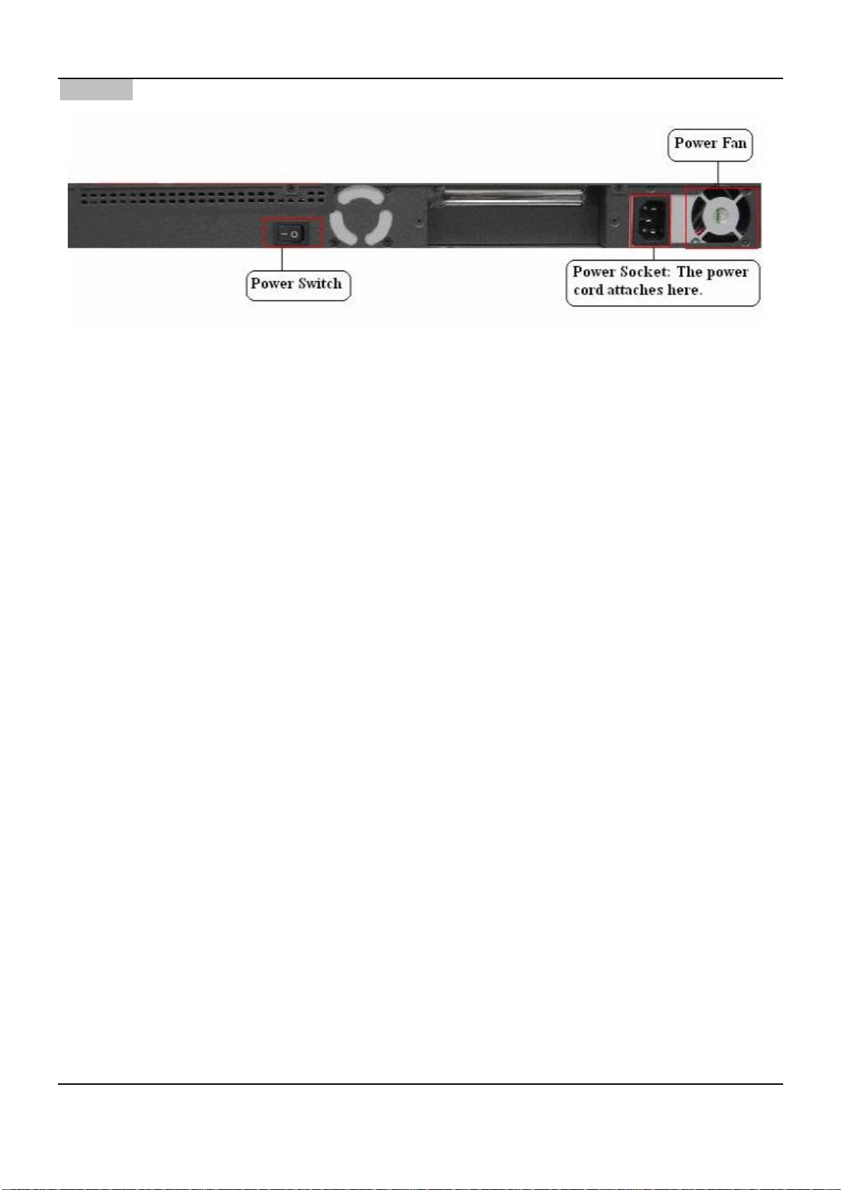
Rear Panel
Power Fan: Keeps the power cool.
Power Socket: The power cord is attached here.
Power Switch: Turns on and off the machine.
Chapter 3. Hardware Installation
3.2 Package Contents
The standard package of the DSA-6100 includes:
y DSA-6100 x 1
y Console Cable x 1
y Crossover Ethernet Cable x 1
y Straight-through Ethernet Cable x 1
y Power Cord x 1
y CD-ROM x 1
y Quick Installation Guide x 1
y Screw Set x 1
y Rack Mount Bracket x 1
3.3 System Requirement
y Standard 10/100BaseT including network cables with RJ-45 connectors
y All PCs need to install the TCP/IP network protocol
9
Page 16
3.4 Installation Steps
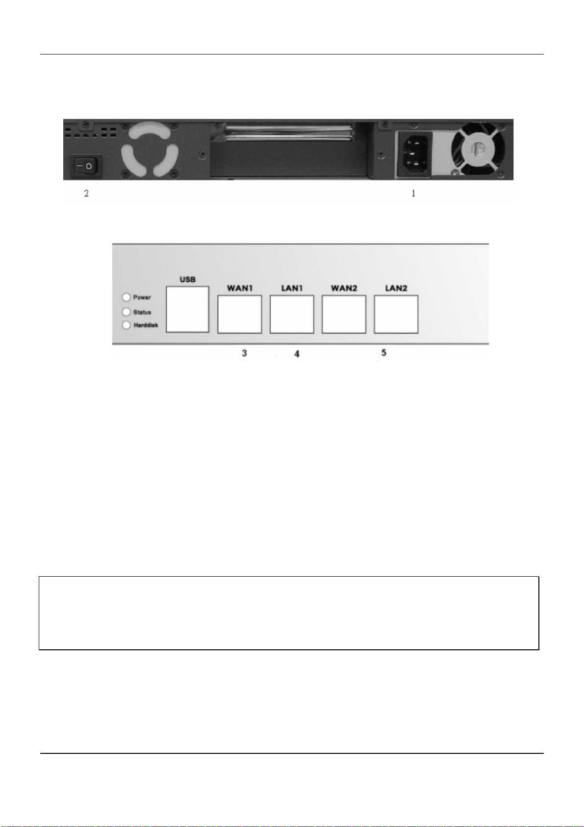
Please follow the steps mentioned below to install the DSA-6100:
1. Connect the power cord to the power socket on the rear panel.
2. Turn on the power switch at the rear panel. The Power LED will light up.
DSA-6100 User Guide
3. Connect an Ethernet cable to the WAN1 Port on the front panel. Connect the other end of the Ethernet cable
to an ADSL modem, a cable modem or a switch/hub of the internal network. The LED of this WAN1 should
light up to indicate a proper connection.
4. Connect an Ethernet cable to LAN1 port with the user authentication function enabled on the front panel. The
default port is LAN1 port. The LAN1 port with authentication function is referred to as Public LAN. Connect
the other end of the Ethernet cable to an AP or switch. The LED of this LAN1 should light up to indicate a
proper connection.
5. Connect an Ethernet cable to LAN2 Port with the user authentication function disabled on the front panel. The
LAN2 port without authentication function is referred to as Private LAN and the administrator can enter the
administrative user interface to perform configurations via Private LAN. Connect the other end of the Ethernet
cable to a client’s PC. The LED of this LAN2 should light up to indicate a proper connection.
Attention: Usually a straight RJ-45 can be applied if the DSA-6100 is connected to a hub/computer which
supports automatic crossover, such as the Access Point. However, after the Access Point hardware resets, the
DSA-6100 may not be able to connect to the Access Point while conne cting with a straight cable, unless the cable
is pulled out and plug-in again. This scenario does NOT occur while using a crossover cable.
After the hardware of the DSA-6100 is installed completely, the system is ready to be configured in the following
sections. This manual will guide you step by step to set up the system using a single DSA-6100 to manage the
network.
10
Page 17

Chapter 4. Web Interface Configuration
Chapter 4. Web Interface Configuration
This chapter provides further detailed information on setting up the DSA-6100. The administration system allows
you to set various networking parameters, such as to enable and to customize network services, to manage user
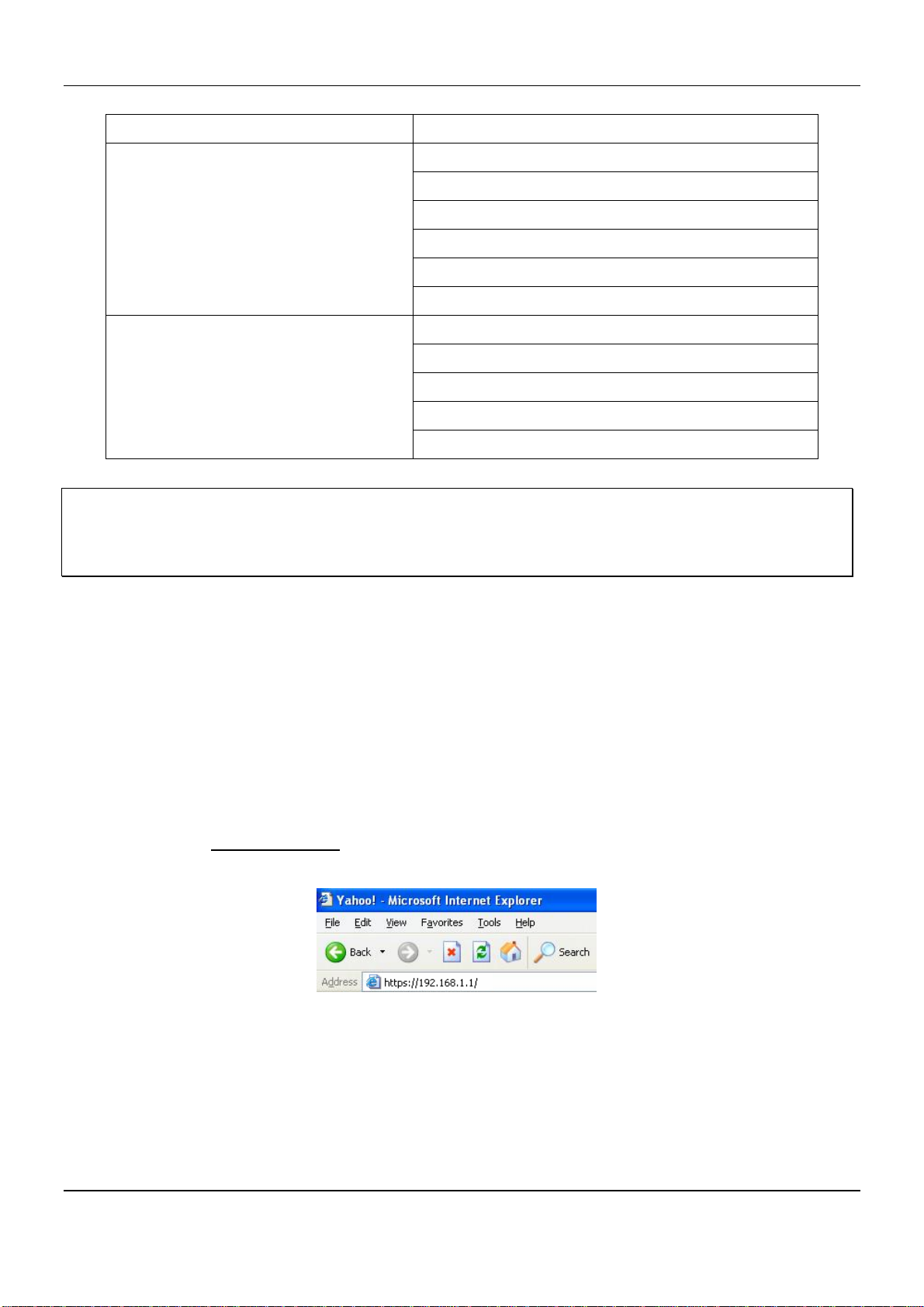
accounts and to monitor user status. The following table shows all the functions of DSA-6100. The administration
functions are separated into several categories: System Configuration, Network Configuration, AP Management,
User Authentication, Status and Tool.
OPTION FUNCTION
System Configuration
Network Configuration
AP Management
Configuration Wizard
System Information
WAN1 Configuration
WAN2 & Failover
LAN1 Configuration
LAN 2 Configuration
Network Address Translation
Privilege List
Monitor IP List
Walled Garden List
Proxy Server Properties
Dynamic DNS
IP Mobility
AP List
AP Discovery
Manual Configuration
Template Settings
Firmware Management
AP Upgrade
User Authentication
Authentication Configuration
Policy Configuration
Black List Configuration
Guest User Configuration
Additional Configuration
11
Page 18
DSA-6100 User Guide
OPTION FUNCTION
Status
Tool
System Status
Interface Status
Current Users
Traffic History
Notification Configuration
Online report
Change Password
Backup /Restore Setting
Firmware Upgrade
Ping Utility
Restart
Note: After finishing the configuration, please click Apply and pay attention to see if a restart message appears at
the bottom of the screen. If the message appears, the system must be restarted to allow the configurations to take
effect. All on-line users will be disconnected during restart.
Web Management Interface
The DSA-6100 provides a web management interface for configuration. After completing the hardware installation,
the administrator can configure the DSA-6100 via web browsers with JavaScript enabled such as Internet Explorer
version 6.0.
After the basic installation has been completed according to the instructions of the previous chapter, the DSA-6100
can further be configured with the following steps:
1. Use the network cable of the 10/100BaseT to connect a PC to the Private LAN (LAN2), and then start a
browser (such as Microsoft IE). Next, enter the gateway address for that port in the opened webpage, the
default which is https://192.168.1.1
. A login screen will then appear. Enter “admin” for the default username
and password and click Enter to log in.
Once the DSA-6100 has been connected, the Administrator Login Page will appear. Enter “admin” for both
the default username and password in the Username and Password fields. Select the Enter button to log in.
12
Page 19

Chapter 4. Web Interface Configuration
Note: If you are unable to get to the login screen, please check the IP address used. The IP address should be in
the same subnet of the default gateway. For using static IP in TCP/IP setting, set a static IP address such as
192.168.1.x for your network interface and then open a new browser again.
2. After successfully logging into the DSA-6100, the Administration System page of the web management
interface will appear. To log out of the system when completed, select the Logout icon on the upper right
corner of the interface to return to the Administrator Login Page.
13
Page 20
DSA-6100 User Guide
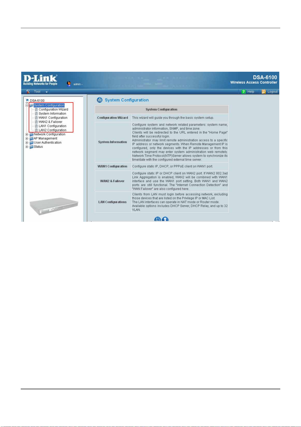
4.1 System Configuration
This section relates to system configuration and provides the information on the following functions: Configuration
Wizard, System Information, WAN Configuration and LAN Configuration.
14
Page 21
Chapter 4. Web Interface Configuration
4.1.1 Configuration Wizard (Also served as Quick Installation Guide)
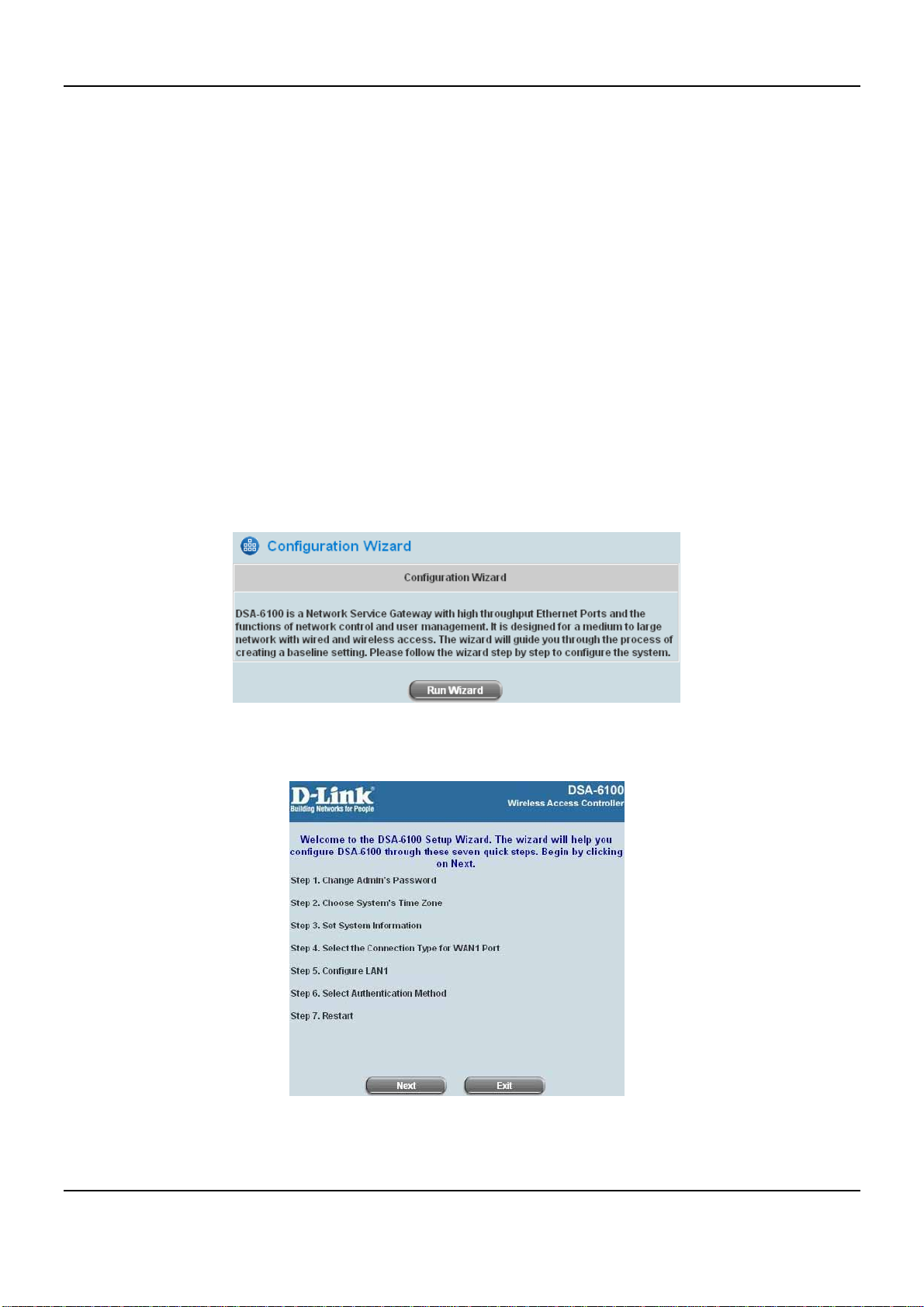
There are two ways to configure the system. One is by using the Configuration Wizard, and the other is by
changing the setting manually. The Configuration Wizard uses seven simple steps to provide the easy set up of the
DSA-6100. These steps may also be used as the Quick Installation Guide. The 7 steps are listed below:
1. Change the Admin Password
2. Choose the System’s Time Zone
3. Set the System Information
4. Select the Connection Type for WAN1 Port
5. Configure LAN1
6. Select Authentication Method
7. Restart
Click System Configuration to go to the System Configuration page.
Click the System Configuration from the left menu, and the System Configuration page will appear. Next, click
on the buttons, Configuration Wizard then Run Wizard to start the wizard.
y Running the Wizard
A welcome screen that briefly introduces the 7 steps will appear. Click Next to begin.
15
Page 22
DSA-6100 User Guide
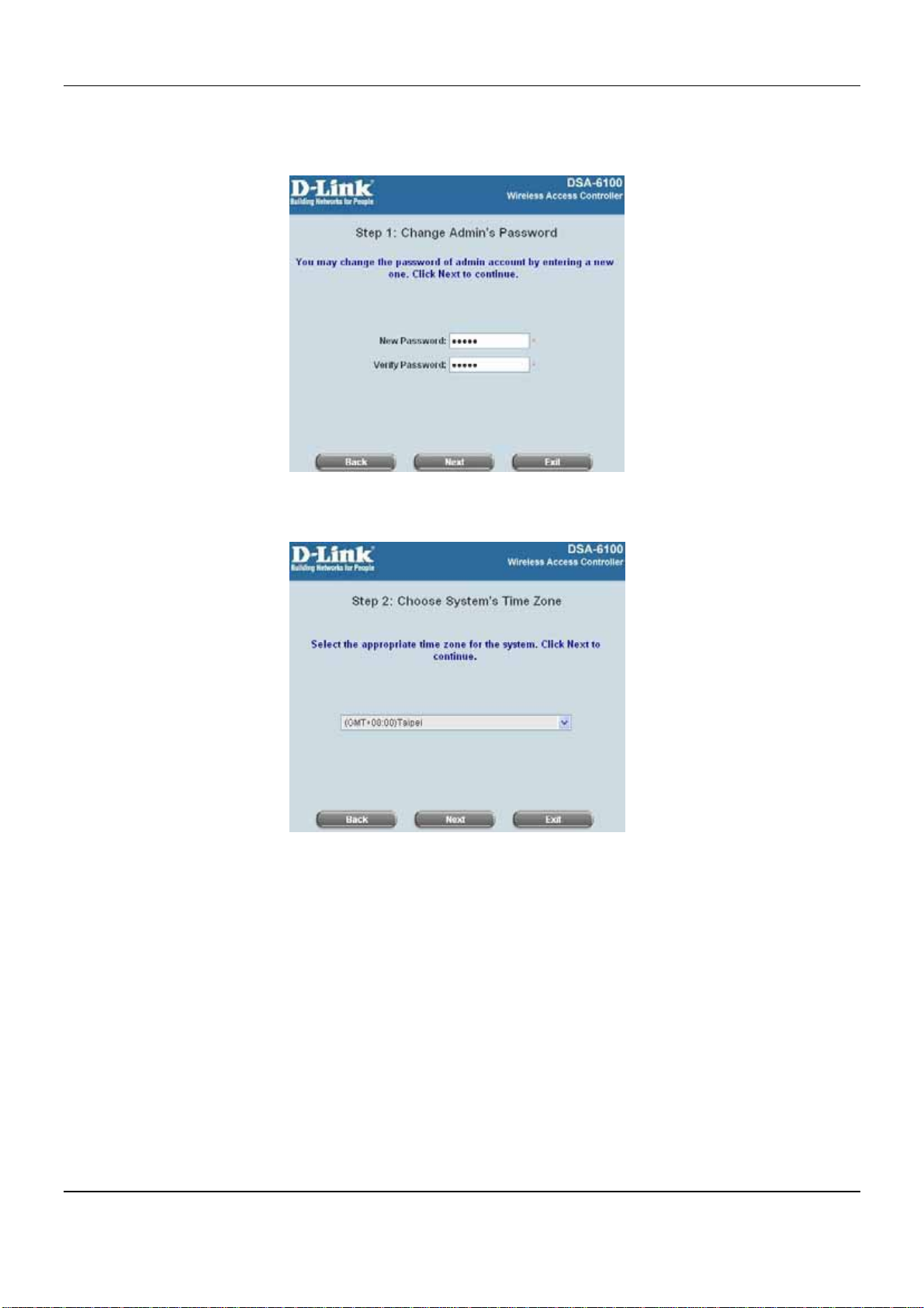
y Step 1: Change Admin’s Password
Enter a new password for the admin account and retype it in the Verify Password field (twenty-character
maximum and no spaces). Click Next to continue.
y Step 2: Choose System’s Time Zone
Select a proper time zone via the pull-down menu. Click Next to continue.
y Step 3: Set System Information
Home Page: Enter the URL to where the clients should be directed when they are properly authenticated.
NTP Server: Enter the URL of the external time server for the DSA-6100 time synchronization or use the
default.
DNS Server: Enter a DNS Server provided by the ISP (Internet Service Provider). Contact the ISP if the DNS
IP Address is unknown.
Click Next to continue.
16
Page 23
Chapter 4. Web Interface Configuration
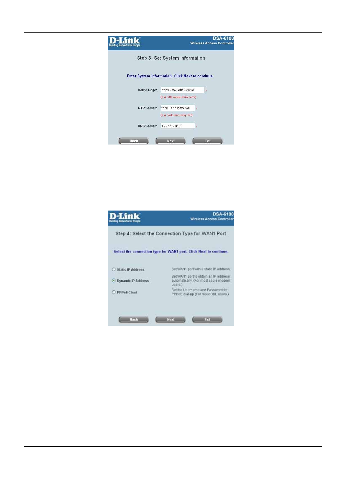
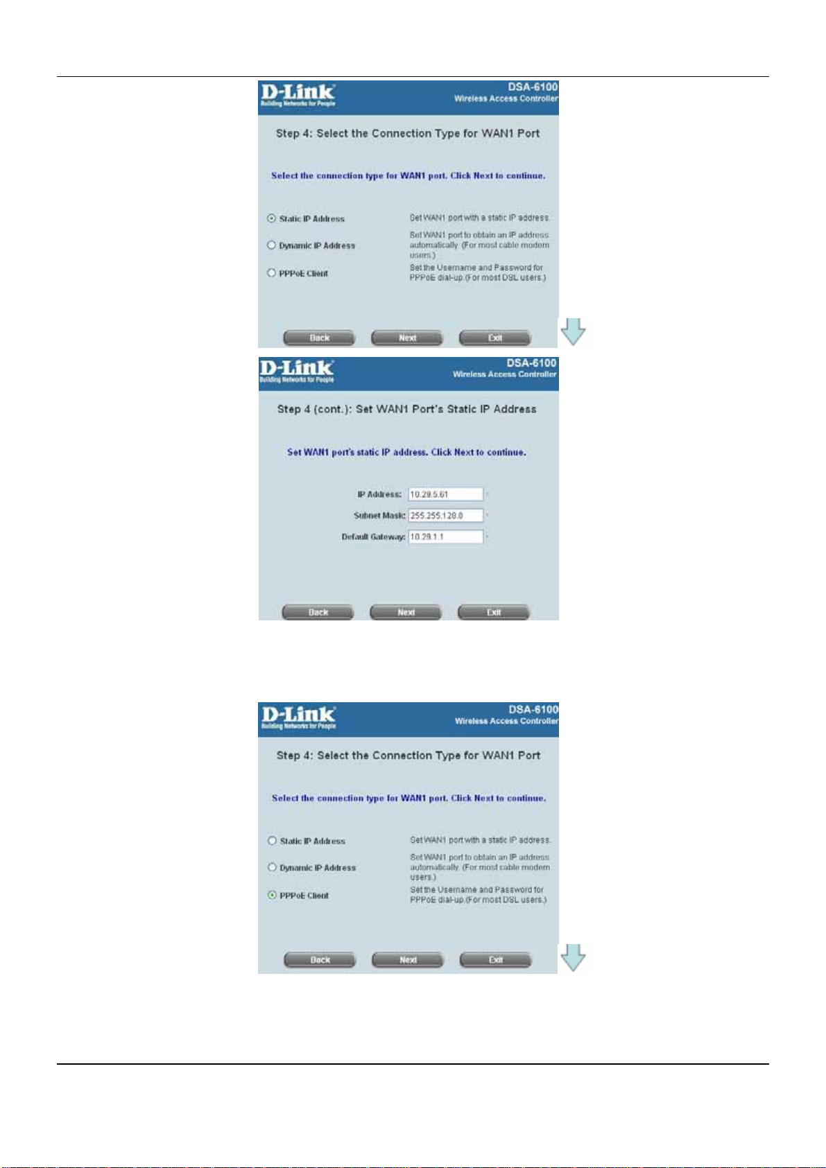
y Step 4: Select the Connection Type for WAN1 Port
There are three types of WAN port to select: Static IP Address, Dynamic IP Address and PPPoE Client.
Select a proper Internet connection type and click Next to continue.
Dynamic IP Address
If this option is selected, an appropriate IP address and related information will be assigned automatically.
Click Next to continue.
Static IP Address: Set WAN1 Port’s Static IP Address
Enter the “IP Address”, “Subnet Mask” and “Default Gateway” provided by the ISP.
Click Next to continue.
17
Page 24
DSA-6100 User Guide
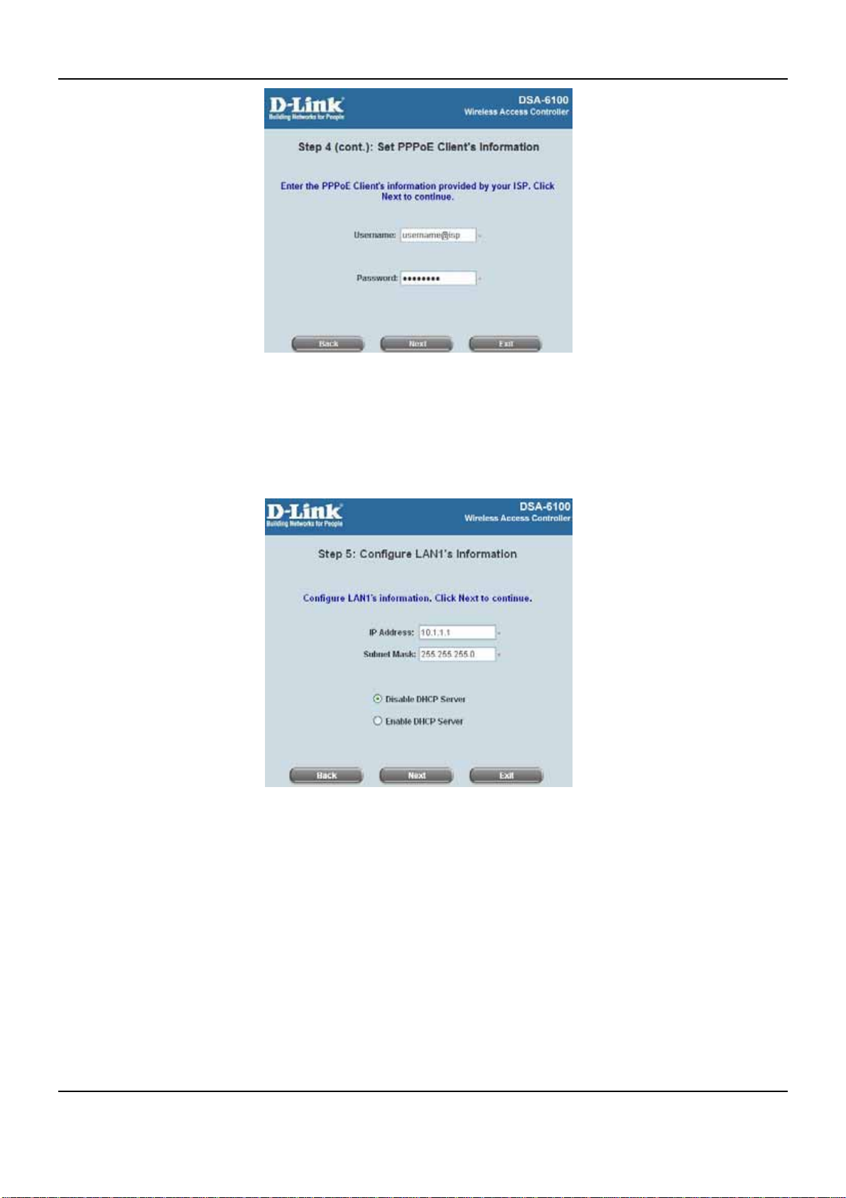
PPPoE Client: Set PPPoE Client’s Information
Enter the “Username” and “Password” provided by the ISP.
Click Next to continue.
18
Page 25
Chapter 4. Web Interface Configuration
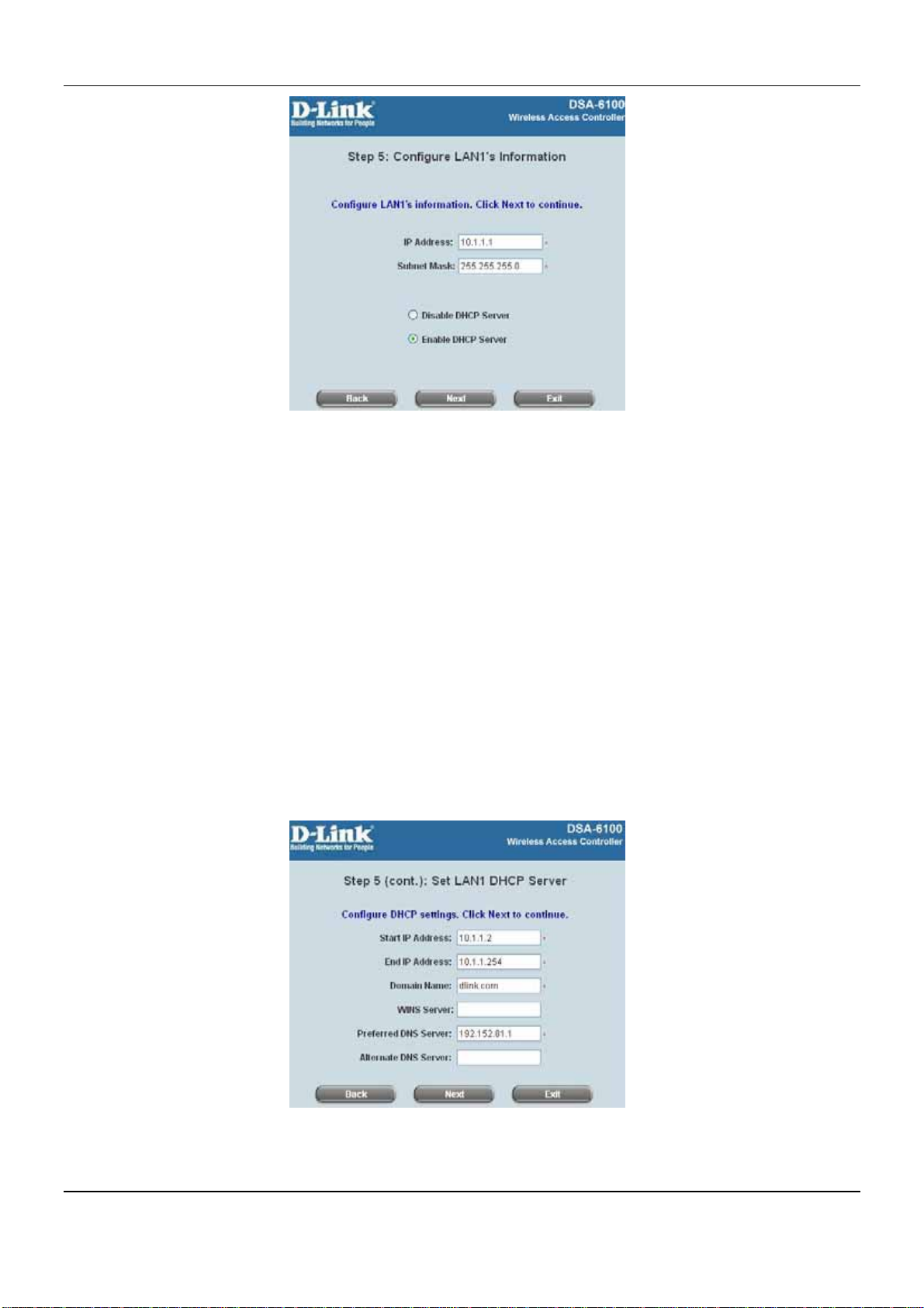
y Step 5: Configure LAN1’s Information
IP Address: Enter the Public LAN port IP Address or use the default.
Subnet Mask: Enter the Public port Subnet Mask or use the default.
Disable DHCP Server: If the DHCP server is disabled, the Public LAN clients must be configured with an IP
address manually.
Enable DHCP Server: When the option is selected, the DSA-6100 will automatically provide the necessary
IP address to all Public LAN clients.
Click Next to continue.
19
Page 26
DSA-6100 User Guide
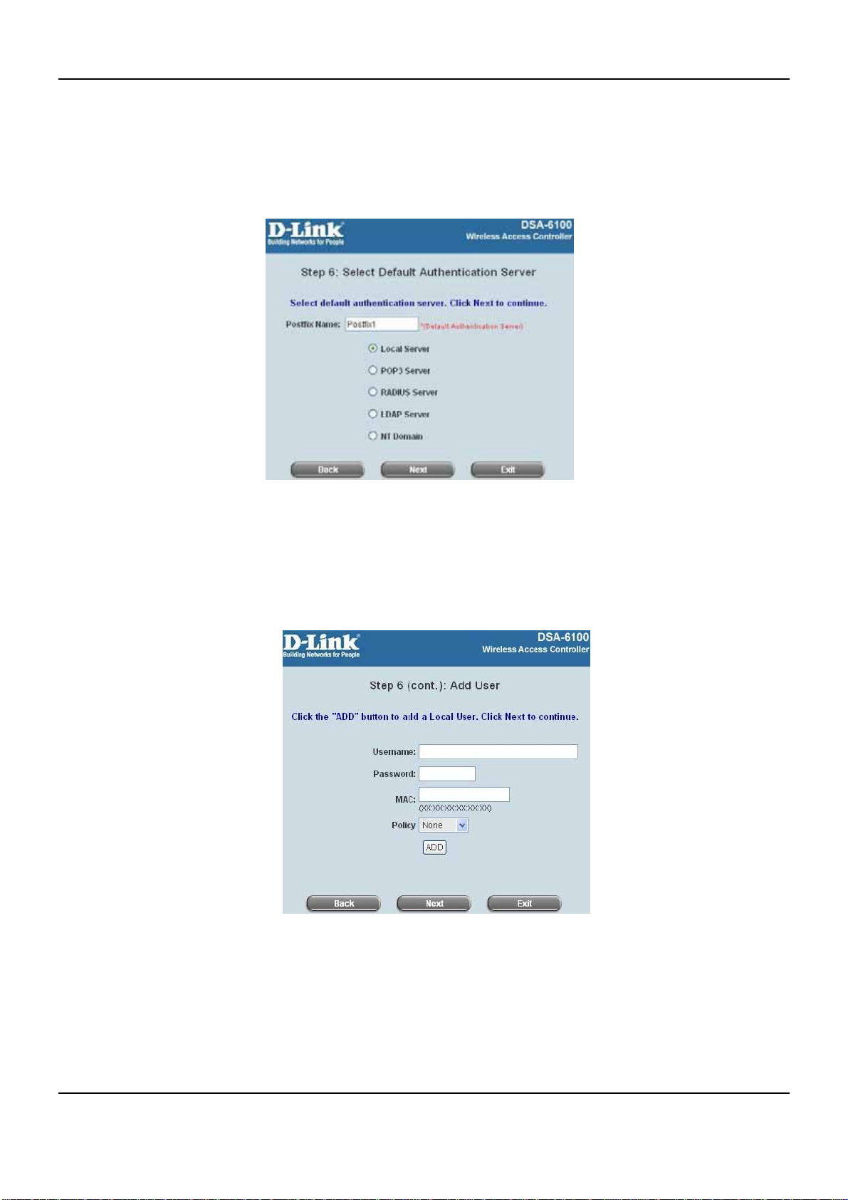
y Step 5 (cont.): Set LAN1 DHCP Server
If the Enable DHCP Server option is selected, more information about the LAN1 DHCP server will be needed.
Fields marked with red asterisks must be filled in.
Start IP Address: The start IP address of the DHCP scope of LAN1.
End IP Address: The end IP address of the DHCP scope of LAN1.
These IP address will be assigned to the LAN1 clients. (Note: Be sure that IP address assigned in this
range is NOT used in other setting of DSA-6100.)
Domain Name: Enter a domain name provided by your ISP (e.g. dlink.com).
WINS Server: Enter the IP address of the WINS server.(Windows Internet Naming Service Server) This field
is optional.
Preferred DNS Server: The DNS Server settings are provided by your ISP. Only the Preferred DNS Server
field is mandatory. Contact your ISP if you are unsure of the DNS Server settings.
Alternate DNS Server: The DNS Server settings are provided by your ISP. The field is optional. Click Next to
continue.
20
Page 27
Chapter 4. Web Interface Configuration
y Step 6: Select Default Authentication Server
Please specify the postfix name for this authentication method. The Postfix Name field (e.g. Local) will be
used as the postfix name (e.g. username@Local). An authentication method has to be selected from one of
the five options appeared in this window (Local User is selected for this setup example).
Click Next to continue.
Local User - Add User
A new user can be added to the local user data base. To add a user, enter the Username (e.g. test),
Password (e.g. test), MAC (optional) and assign it a policy (or use the default). Upon completing a user
adding, more users can be added to this authentication method by clicking the ADD button.
Click Next to continue.
21
Page 28
DSA-6100 User Guide
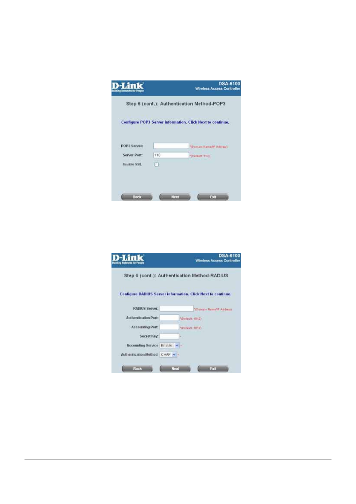
User Authentication Method-POP3
Enter IP/Domain Name and server port of the POP3 server provided by the ISP, and then choose enable
SSL or not.
Click Next to continue.
User Authentication Method-RADIUS
Enter RADIUS server IP/Domain Name, authentication port, accounting port and secret key, then
choose whether to enable accounting service. Next, choose the desired authentication method.
Click Next to continue.
22
Page 29
Chapter 4. Web Interface Configuration
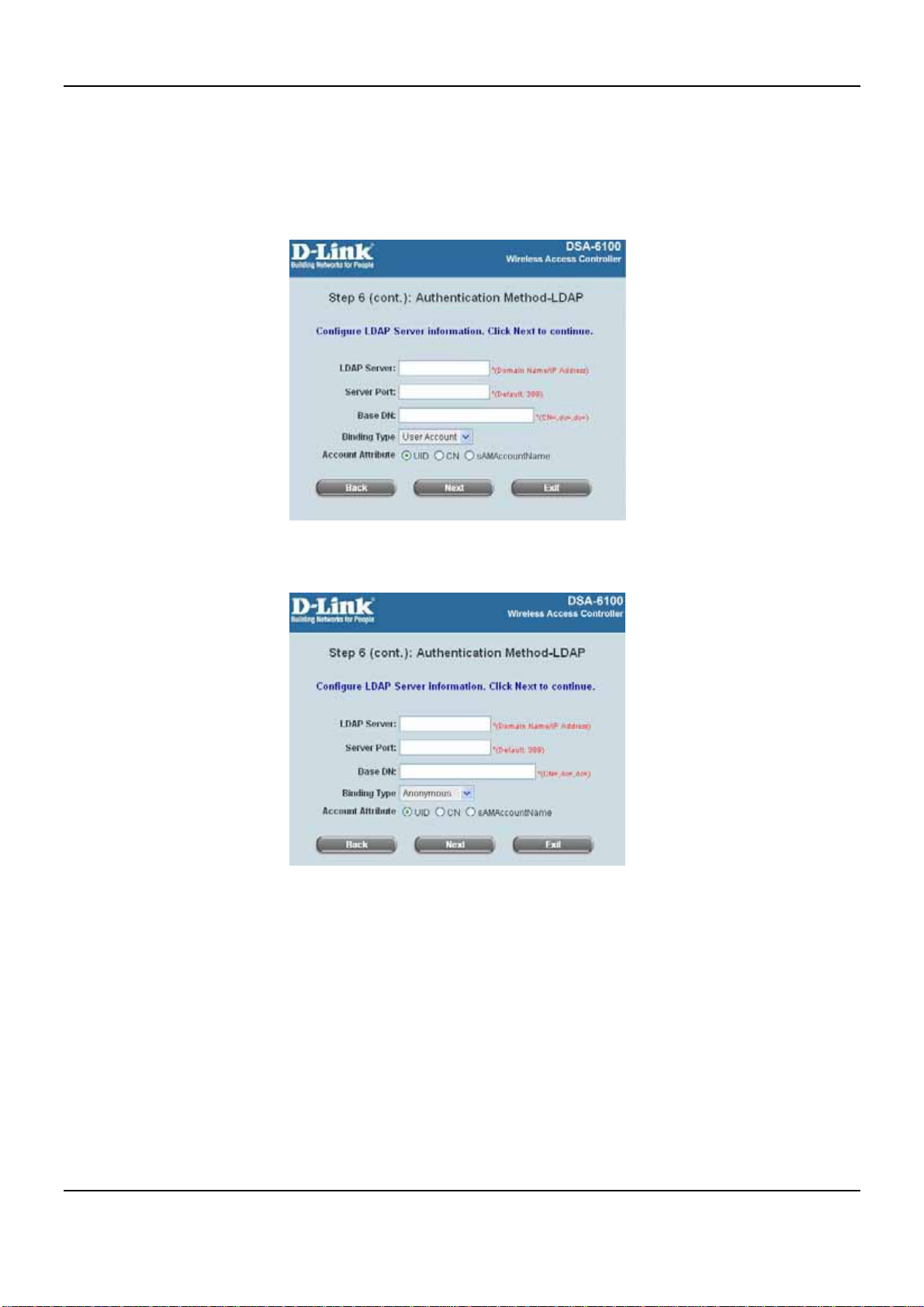
User Authentication Method-LDAP
Add a new user to the LDAP user database. Enter the “LDAP Server”, “Server Port” and “Base DN”
and select one kind of Binding Type and Account Attribute to access the LDAP server.
If the User Account binding type is selected, the system will use the Base DN to be the user account to
access the LDAP server.
If Anonymous binding type is selected, the system will access the LDAP servers without requiring
authentication.
23
Page 30

DSA-6100 User Guide
If Specific DN binding type is selected, username and password in the “Bind RDN” and “Bind
Password” fields must be entered to access the LDAP server.
If Windows AD binding type is selected, please enter the domain name of Windows AD to access the
LDAP server.
Click Next to continue.
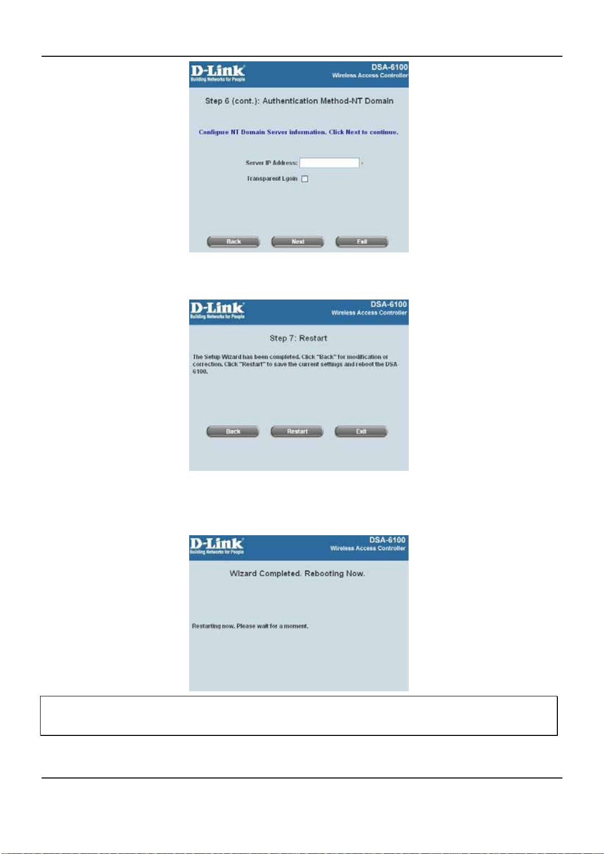
User Authentication Method-NT Domain
When NT Domain User is selected, enter the information for “Server IP Address”, and enable/disable
“Transparent Login”. After this setup is completed, click Next to continue.
24
Page 31
Chapter 4. Web Interface Configuration
y Step 7: Restart
Click Restart to save the current settings and restart DSA-6100. The Setup Wizard is now completed.
y During the DSA-6100 restarting, a “Restarting now. Please wait for a moment.” message will appear on
the screen. Please do not interrupt the DSA-6100 until the Configuration Wizard has disappeared. This
indicates that the restart process has been completed.
Back and Exit: During every step of the wizard, if you wish to go back to m odify the settings, pl ease click the Bac k
button to go back to the previous step. Click Exit to leave the Wizard.
25
Page 32
DSA-6100 User Guide
4.1.2 System Information
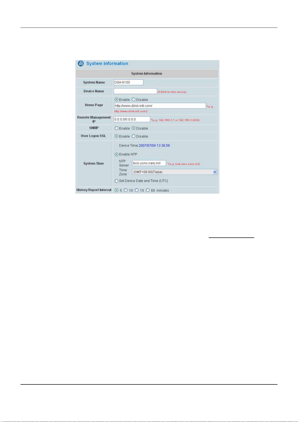
The system and network related parameters such as System Name, Device Name, Homepage Redirect URL,
Management IP Address List, and User Logon SSL can be configured from the menu as shown below.
y System Name: The name of this system. Set the system’s name or use the default.
y Device Name: FQDN (Fully-Qualified Domain Name). This is the domain name used in login page. For
example, if Device Name is dlink.com, the URL of login page will be https://dlink.com/loginpages/login.shtml.
y Home Page: Enter the website of a Web Server to be the homepage. User will be directed to this webpage
after successful login. Usually, the homepage is the company’s website, such as http://www.dlink.com
Regardless of the original webpage set in the users’ computer, they will be redirected to this page after login.
y Remote Management IP: Set the IP Address or the IP Subnet with a system which is able to connect to the
web management interface via the authenticated port. For example: 10.2.3.0/24 means that as long as an
administrator is within the IP address range of 10.2.3.0/24, he or she can reach the administration page of the
DSA-6100. If the administrator configures a single IP, such as 10.2.3.5, only this IP address can reach the
administration page.
y SNMP: Configure IP address and Community ID of external SNMP management device. This system supports
SNMP v.3.
y User Logon SSL: Enable SSL, HTTPS or disable HTTP when user login with encryption to have a safer login
process.
y System Time: DSA-6100 supports NTP communication protocol to synchronize the network time. Please
.
specify the IP address of a server and select the desired time zone in the system configuration interface for
adjusting the time automatically. (Universal Time is Greenwich Mean Time, GMT). Time can also be set
manually when by selecting “Set Device Date and Time”. Please enter the date and time for these fields.
y History Report Interval: Time interval to update length of minutes that traffic log in the Traffic History page will
be updated by the unit.
26
Page 33
Chapter 4. Web Interface Configuration
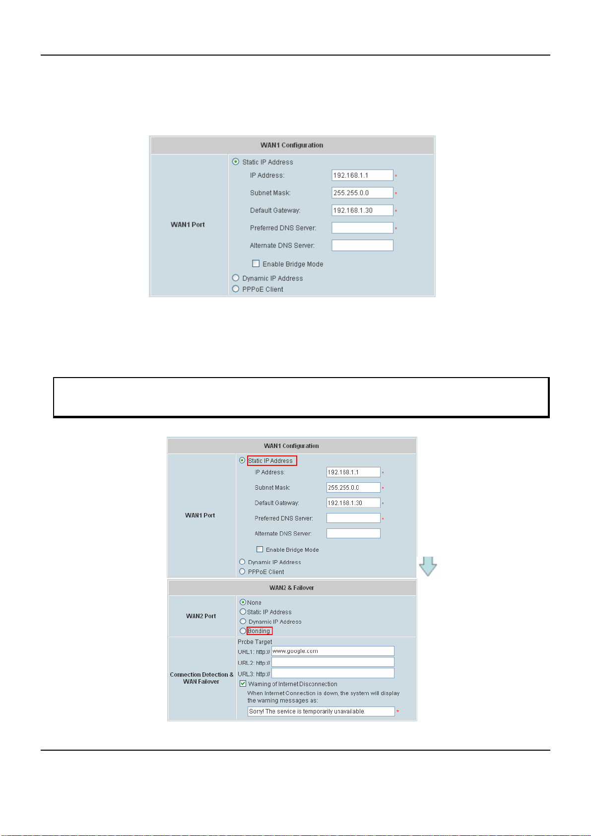
4.1.3 WAN1 Configuration
System supports three different WAN connection types for the WAN1 Port configuration including: Static IP
Address, Dynamic IP Address, and PPPoE Client.
y Static IP Address: Manually specifying the IP address of the WAN1 Port regarding your ISP network
information, which is applicable for the network environment where IP address cannot be obtained
automatically.
Note: The option of Bonding for WAN2 is only available when WAN1 is set to static IP address.
The fields with red asterisks are required. Please fill in these fields.
27
Page 34
DSA-6100 User Guide
¾ IP Address: The IP address of the WAN1 port.
¾ Subnet Mask: The subnet mask of the WAN1 port.
¾ Default Gateway: The gateway of the WAN1 port.
¾ Preferred DNS Server: The primary DNS Server of the WAN1 port.
¾ Alternate DNS Server: The substitute DNS Server of the WAN1 port. This is not required.
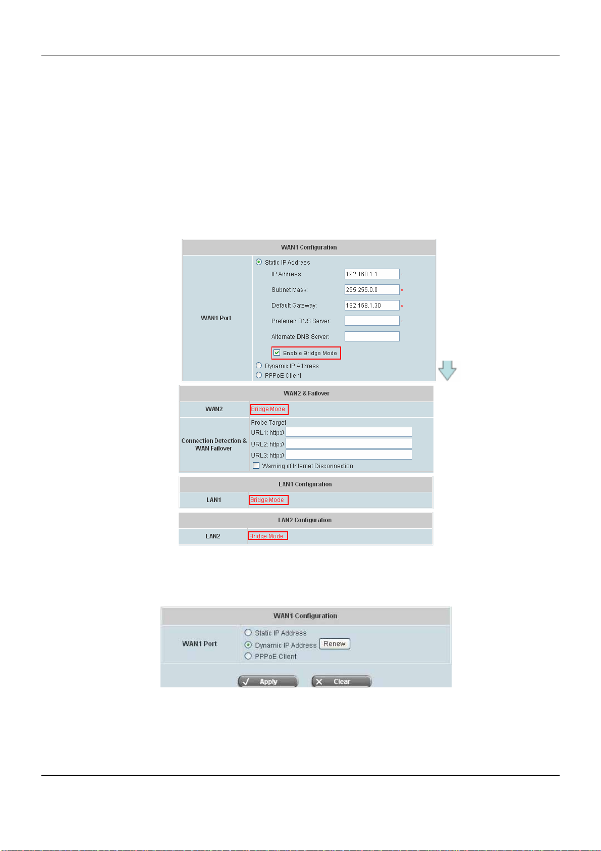
¾ Enable Bridge Mode: Bridge all WAN and LAN interfaces. These interfaces will be in the same
network segment. When the WAN1 is set to use a static IP address and “Enable Bridge Mode” is
checked, the DSA-6100 will act as a switch and WAN2, LAN1 and LAN2 ports will share the same
static IP address from WAN1. The pictures below are the results on the WAN2 and LAN2 when
Bridge Mode is enabled on the WAN1 interface.
y Dynamic IP address: Configure WAN port settings automatically using external DHCP Server. It is only
applicable for the network environment where the DHCP Server is available in the network. Click the Renew
button to get an IP address.
28
Page 35
Chapter 4. Web Interface Configuration
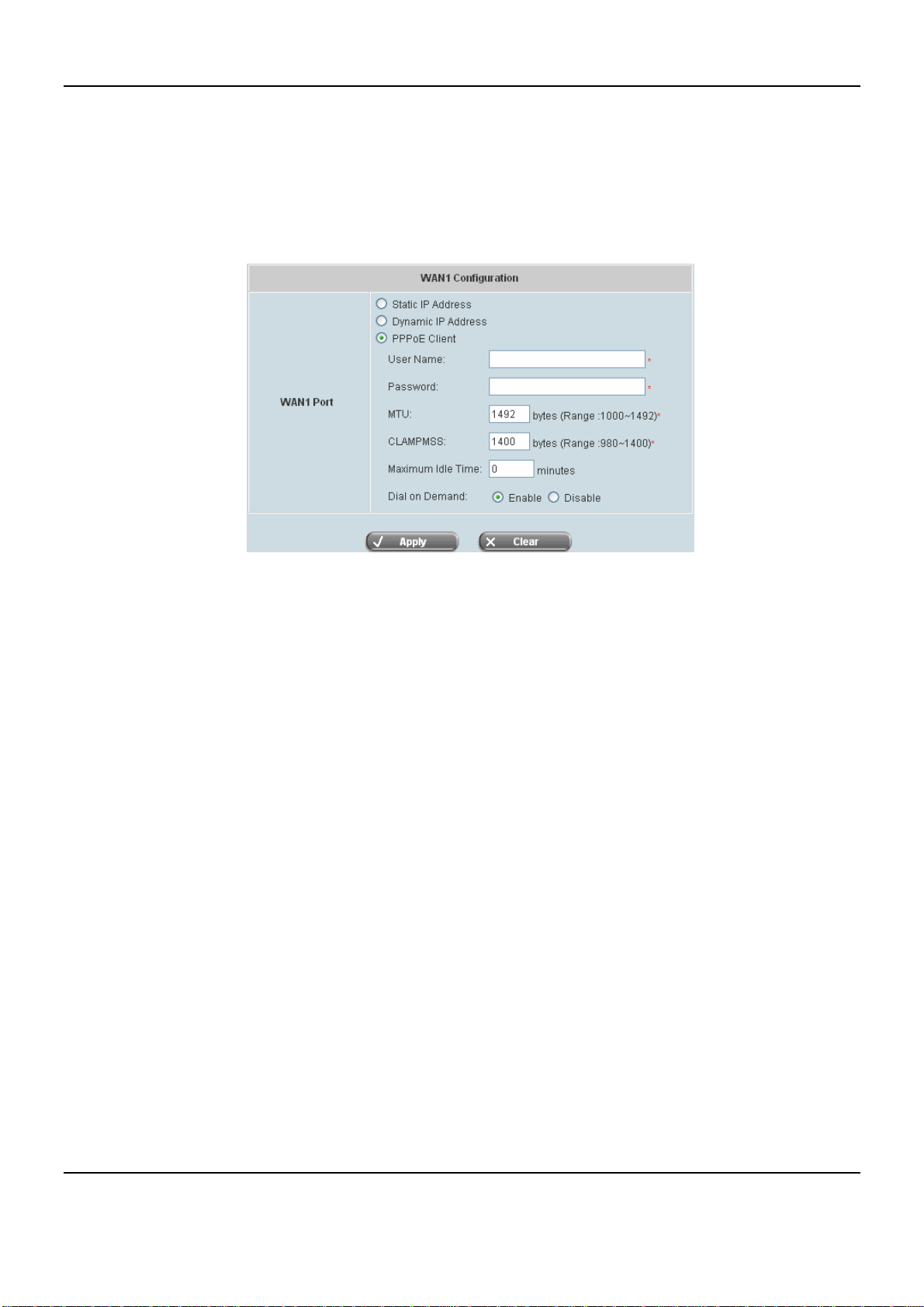
y PPPoE Client: Common ADSL connection type. Enter User Name and Password of your PPPoE account.
When dial on Demand is enabled, you can set the idle timer before the system is disconnected from the
Internet. When selecting PPPoE to connect to the network, please set the “User Name” and “Password”
from your ISP to access the network. There is a Dial on demand function under PPPoE and if this function is
enabled, you can set a Maximum Idle Time. When the idle time is reached, the system will automatically
disconnect itself.
29
Page 36
DSA-6100 User Guide
4.1.4 WAN2 & Failover
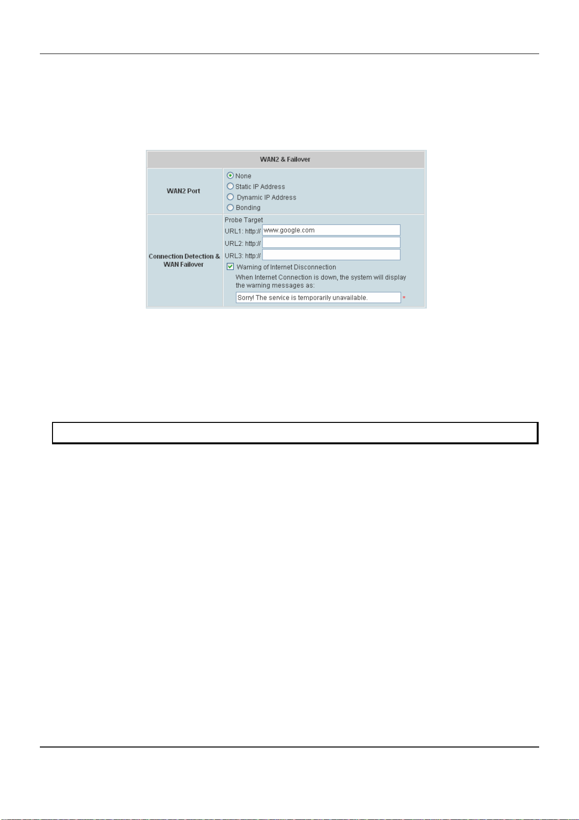
WAN2 can be configured to one of the following types: None, Static IP Address, Dynamic IP Address and
Bonding. None means that WAN2 Port is disabled. Bonding is shown as one of the option when WAN1 is set to
Static IP Address.
• WAN2 Port:
¾ None: No WAN2 connection or WAN2 connection is disabled
¾ Static IP Address, Dynamic IP Address: Please refer to WAN1 Port settings
¾ Bonding: When enabled, it allows administrators to increase the uplink bandwidth capacity
beyond the capacity of one single WAN port (WAN1 and WAN2 links are combined and outgoing
packets are transmitted in a specific round-robin order)
Note: The option of Bonding is only available when WAN1 is set to Static IP Address.
• Connection Detection & WAN Failover:
¾ Probe T arget : To verify the connection to the Internet, the system keeps up to three target URLs.
These URLs are used for the system as the detect targets of WAN Failover and Warning of
Internet Disconnection. At least one URL is required for the system to verify the Internet
connection.
¾ WAN Failover: When enabled and WAN1 connection fails, the traffic will be routed to WAN2
automatically. If the Fallback to WAN1 when possible function is enabled, and WAN1
connection is recovered, the routed traffic will return to WAN1.
¾ Warning of Internet Disconnection: When enabled, the reminding message will appear on
clients’ screens when Internet connection is down.
30
Page 37
Chapter 4. Web Interface Configuration
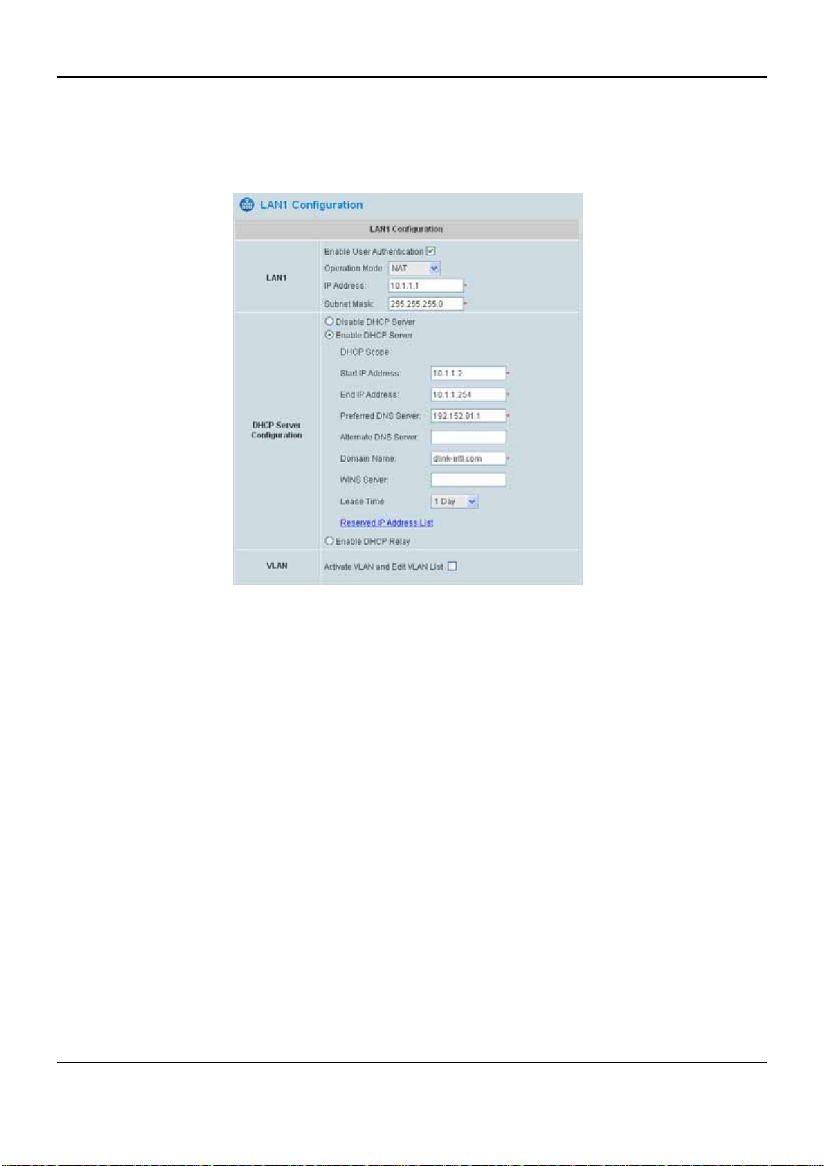
4.1.5 LAN1 Configuration
LAN1 is required to obtain authentication (this configuration can be disabled). In this section, you will be advised on
how to set the related configurations of LAN1 port and DHCP server.
LAN1: These are the basic, global configuration options for LAN1 port.
y Enable User Authentication: When enabled, users on the LAN1 interface are required to log in before
accessing the network. By default, user authentication under LAN1 port is required.
y Operation Mode: The system supports NAT mode and Route Mode.
NAT: All IP addresses of internal hosts connected to the LAN1 port, where the internal hosts belong to the
same network as the LAN1 interface, will be converted into the IP address of the WAN1 interface by the
DSA-6100 and onward to outside the network.
ROUTER: All IP addresses of internal hosts connected to the LAN1 interface will remain the same while
the IP packets travel through WAN1 interface, thus making the DSA-6100 act like a router.
y IP Address: IP address of each network interface.
y Subnet Mask: Subnet Mask of the LAN/VLAN interface.
31
Page 38
DSA-6100 User Guide
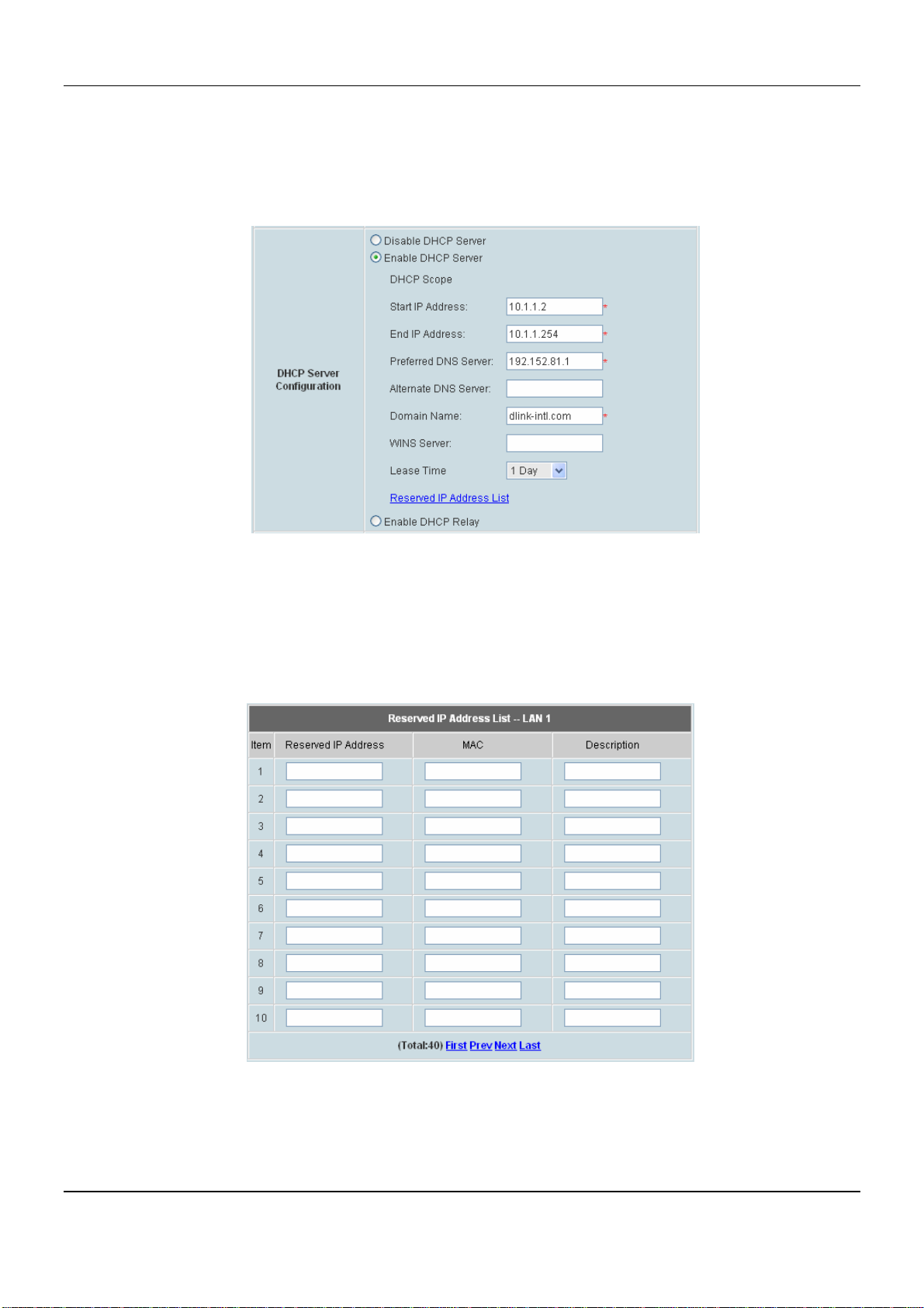
DHCP Server Configuration: DHCP options for LAN1 port include Disable, Enable, and Relay.
y Disable DHCP Server: Disable the function of the DHCP Server.
y Enable DHCP Server: When enabled, related information has to be filled in properly: DHCP Pool Start IP
Address, DHCP Pools End IP Address, Preferred DNS Server, Alternate DNS Server, Domain Name,
WINS Server, Lease Time, and Reserved IP Address List.
If you want to use the reserved IP address function, click on the Reserved IP Address List. The setup
menu of the Reserved IP Address List will appear, as shown in the following picture. Enter the related
Reserved IP Address, the MAC Address of the client, and some Description (optional). When finished, click
Apply to complete the setup. The list reserves IP addresses from predefined DHCP Scope and prevents
systems from issuing these IP address to downstream users.
32
Page 39
Chapter 4. Web Interface Configuration
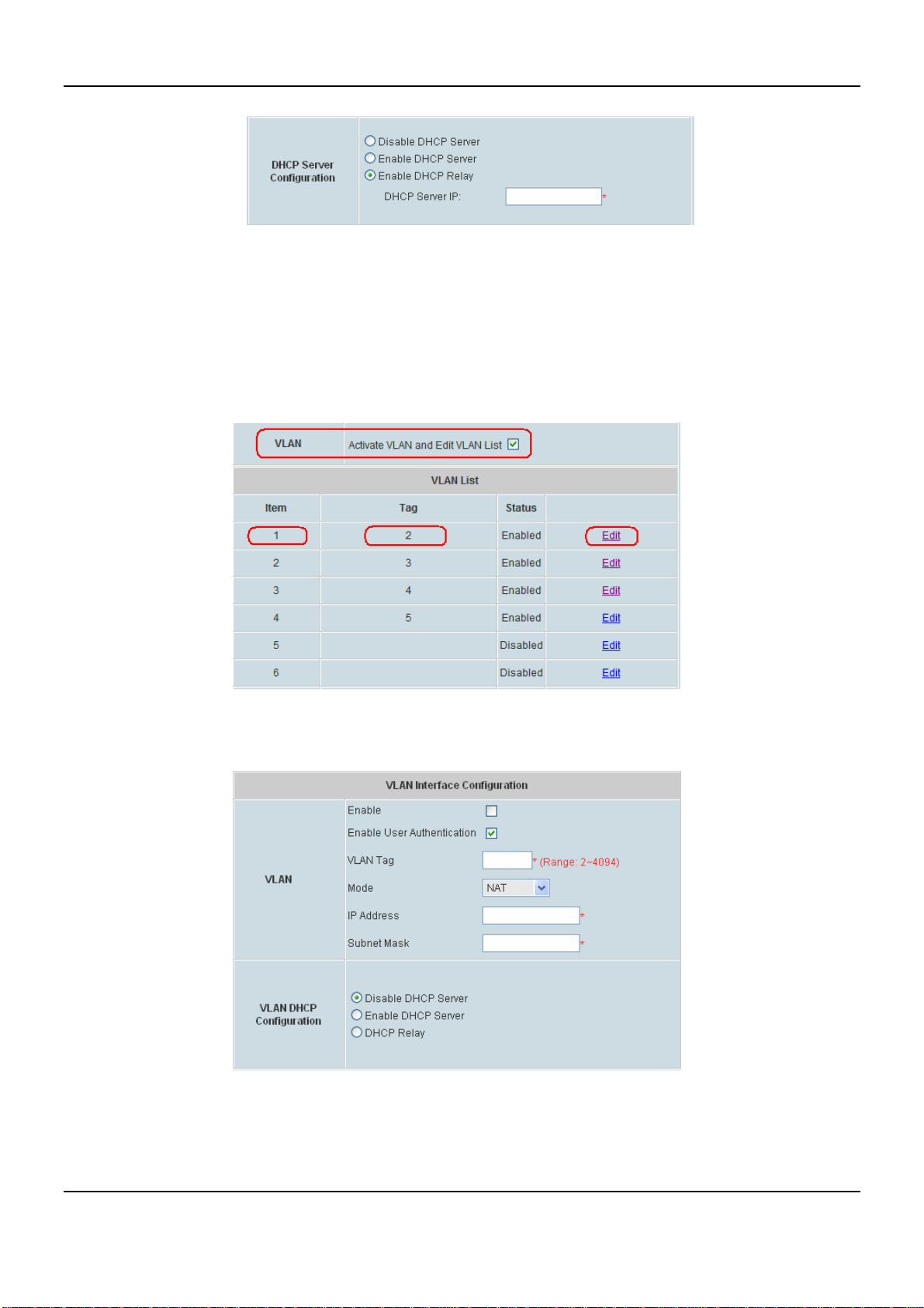
y Enable DHCP Relay: Specify the IP address of the DHCP Relay Server.
VLAN: In the VLAN mode, the LAN interface can be separated into several virtual LAN interfaces. It allows
switches to assign end stations to different virtual LANs.
y Activate VLAN and Edit VLAN List: Select the check box to activate the VLAN. Thereafter, on the VLAN
List, 32 VLANs can be configured accordingly. Select the desired Item and click Edit to configure the
VLAN.
VLAN Interface Configuration for LAN1:
33
Page 40

DSA-6100 User Guide
VLAN:
y Enable: When enabled, this VLAN segment will be active.
y Enable User Authentication: When enabled, users on this VLAN interface are required to log in before
accessing the network.
y VLAN Tag: Enter any integer number within the range of 2 ~ 4094 (1 is reserved for system) as the Tag ID
for this VLAN segment.
y Mode:
o NAT: All IP addresses of hosts on the VLAN interface will be converted into the IP address of the
WAN1 interface and onward to outside the network.
o ROUTER: All IP addresses of hosts on the VLAN interface will remain the same while the IP packets
travel through WAN1 interface, thus making the DSA-6100 act like a router.
y IP address: IP address of each network interface.
y Subnet Mask: Subnet Mask of the LAN/VLAN interface.
VLAN DHCP Configuration: DHCP options for this VLAN interface include Disable, Enable, and Relay.
34
Page 41
Chapter 4. Web Interface Configuration
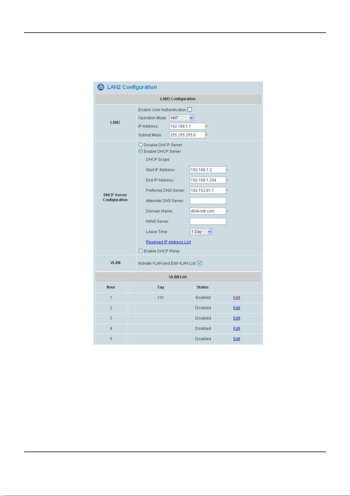
4.1.6 LAN2 Configuration
By default, users on the LAN2 interface are not required to log in before accessing the network, but administrator
can enable the user authentication based upon actual network deployment requirements. Please refer to the
previous section “LAN1 Configuration” for details about the similar configuration of LAN2 port.
LAN2: These are the basic, global configuration options for LAN2 port.
DHCP Server Configuration: DHCP options for LAN2 port include Disable, DHCP, and Relay.
VLAN: To activate the VLAN interfaces for LAN2 port, please check “Activate VLAN and Edit VLAN List”.
Thereafter, on the VLAN List, 32 VLANs can be edited accordingly.
35
Page 42
DSA-6100 User Guide
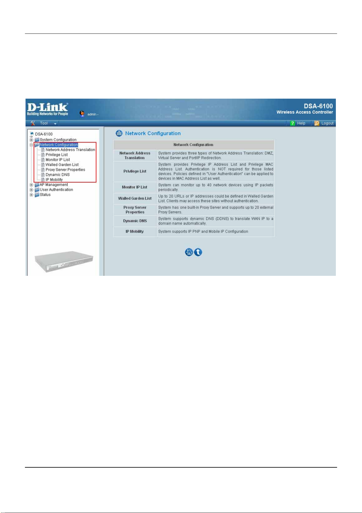
4.2 Network Configuration
This section is used to set all the internet settings. The section provides information on the following functions:
Network Address Translation, Privilege List, Monitor IP List, Walled Garden List, Proxy Server Properties,
Dynamic DNS and IP Mobility.
36
Page 43
Chapter 4. Web Interface Configuration
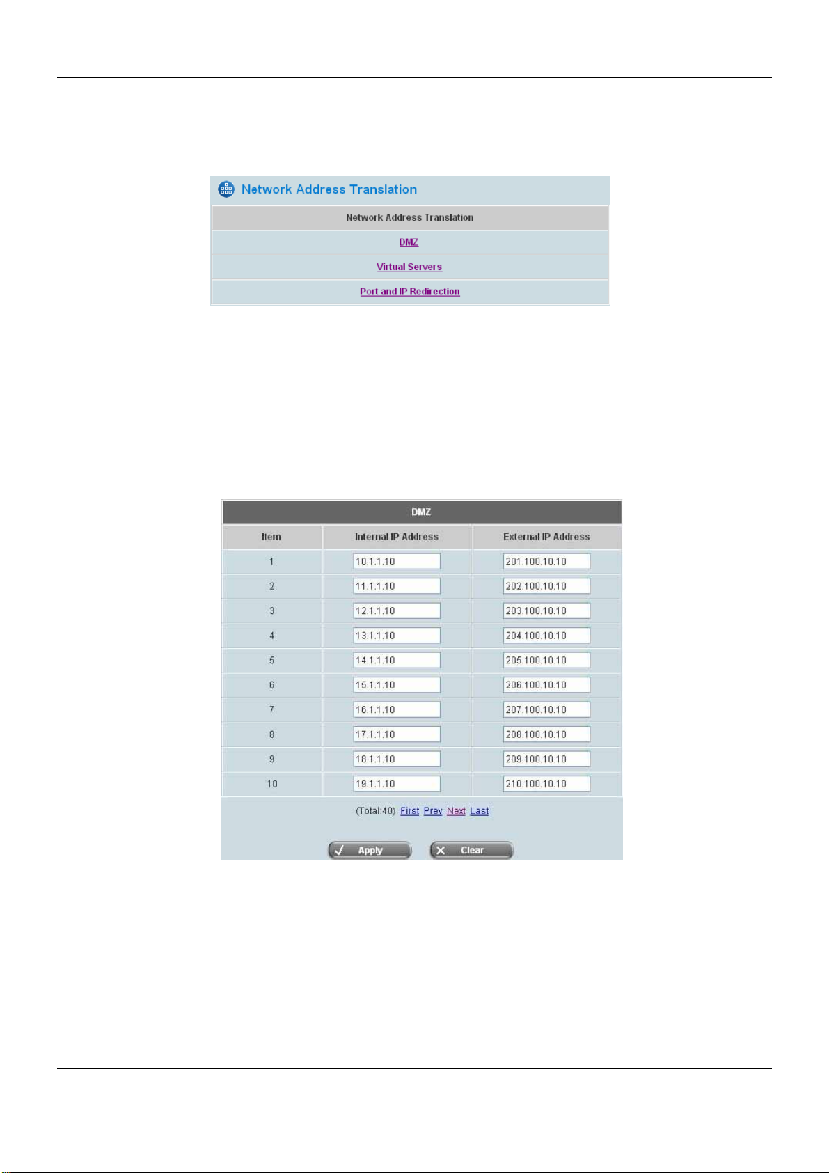
4.2.1 Network Address Translation
There are three options of Network Address Translation that can be set: DMZ, Virtual Servers and Port and IP
Redirect.
y DMZ
De-Militarized Zone. It maps external WAN IP address to the internal LAN IP addresses. A computer within a
DMZ is unprotected by firewall and typically all port accesses are routed through that computer. A router will
forward all traffic to the computer specified in the DMZ if it does not otherwise have a rule for how to forward
traffic on a given port. There are 40 sets of static Internal IP Address and External IP Address available.
These settings will become effective immediately after clicking the Apply button. Click Next to set up more
than 10 IP addresses.
37
Page 44
DSA-6100 User Guide
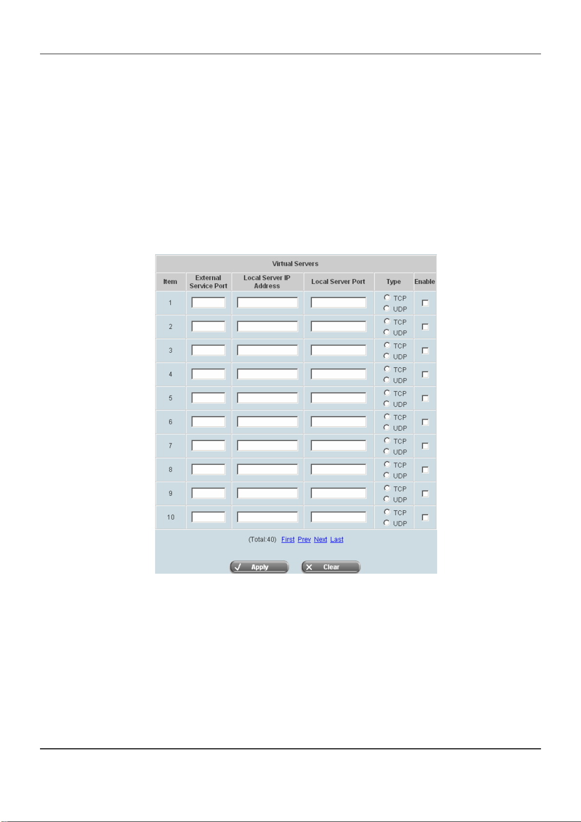
y Virtual Servers
This function allows servers within LAN to become accessible from WAN. This function allows the
administrator to set up to 40 virtual servers, to allow computers not belonging to the managed network (WAN
network), to access the servers in the managed network (LAN network). Enter the “External Service Port”,
“Local Server IP Address” and “Local Server Port” accordingly. Depending on the different services
provided, the network service will be able to use the TCP protocol or the UDP protocol. In the Enable column,
check the desired server to enable. These settings will become effective immediately after clicking the Apply
button.
Virtual Servers will transfer External port to Local port. This function allows servers with specific
communication port within LAN to become accessible from WAN.
38
Page 45
Chapter 4. Web Interface Configuration
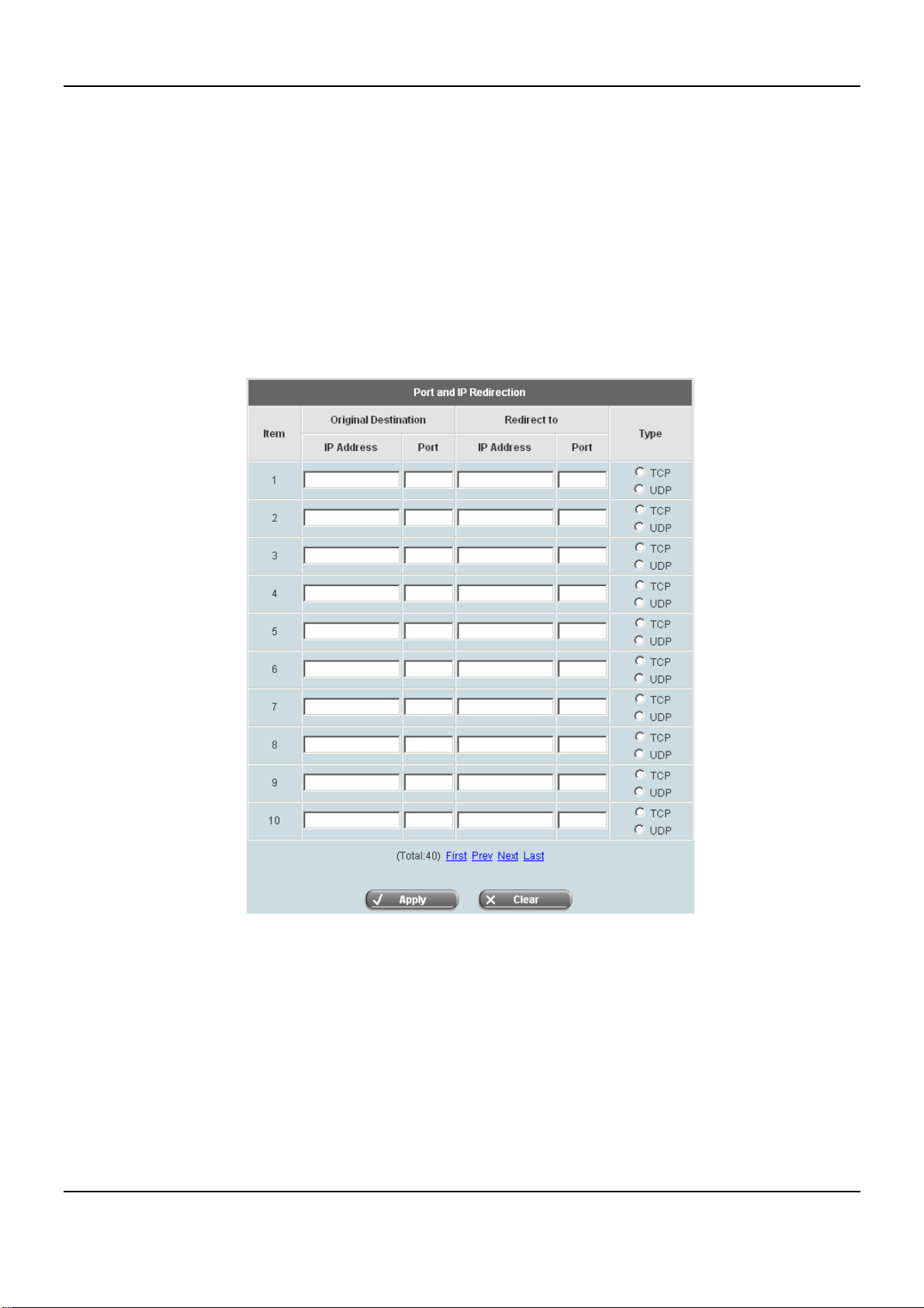
y Port and IP Redirect
When the user attempts to connect to a destination IP address/Port listed here, the connection packet will be
converted and redirected to the corresponding destination. Port and IP Redirection enables the redirection of
the original IP address. When the user attempts to connect to a destination IP address/Port, the connection
packet will be converted and redirected to the corresponding destination. This function allows the administrator
to set up to 40 IP addresses for redirection purpose. Enter the “IP Address” and “Port” of Original
Destination, and the “IP Address” and “Port” of Redirect to. According to the different services provided,
choose the “TCP” protocol or the “UDP” protocol. These settings will become effective immediately after
clicking Apply.
39
Page 46
DSA-6100 User Guide
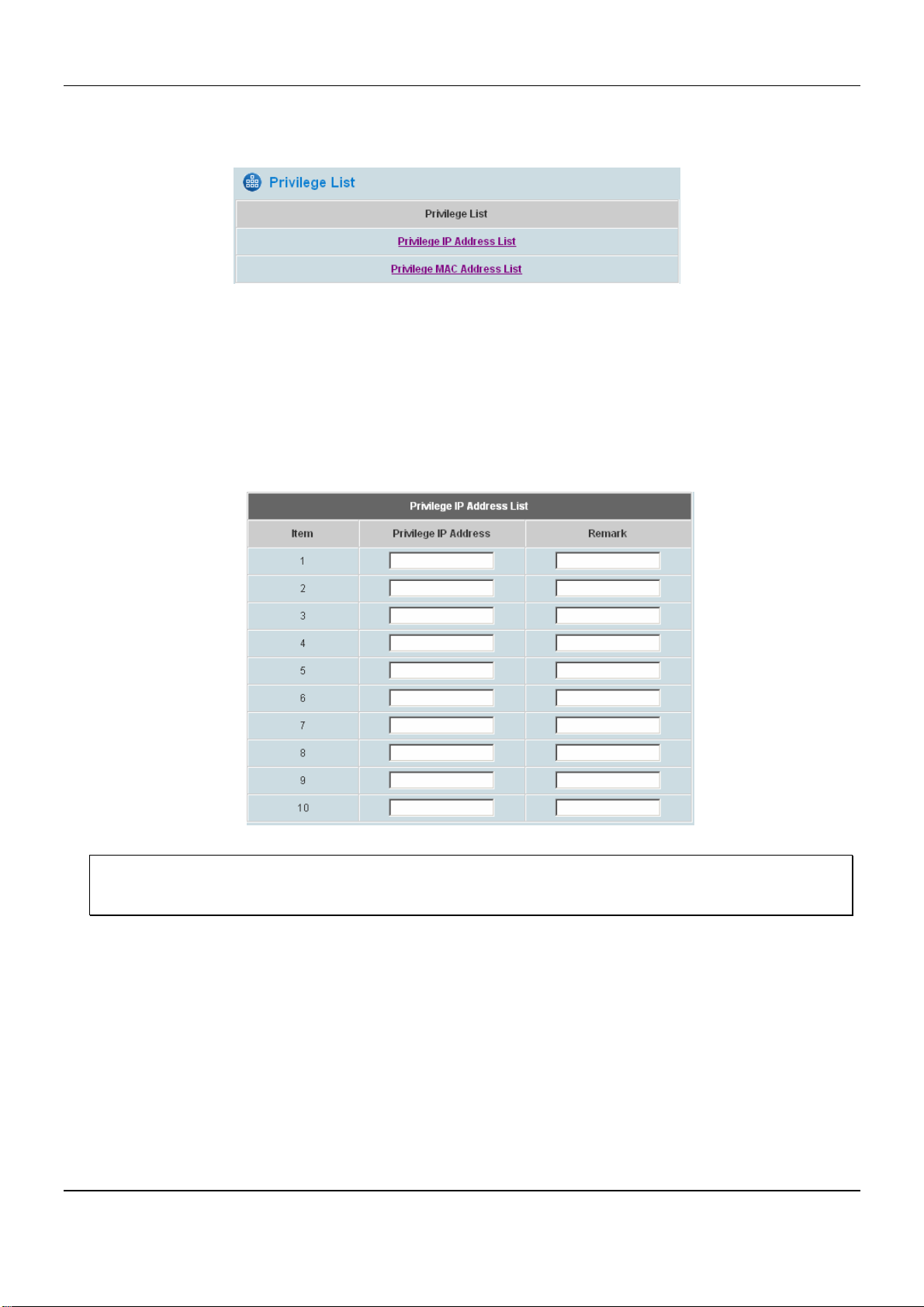
4.2.2 Privilege List
There are two lists that will need to be set: Privilege IP Address List and Privilege MAC Address List.
y Privilege IP Address List
Clients with the IP Address on the List are allowed to access the Internet directly; authentication is not required.
If there are some workstations belonging to the managed server that need to access the network without
authentication, enter the IP addresses to this list. The “Remark” field is not necessary but is useful to keep
track. The DSA-6100 allows up to 100 privilege IP addresses. These settings will become effective
immediately after clicking Apply.
Warning: Permitting specific IP addresses to have network access rights without going through standard
authentication process at the authenticated LAN can result in security risks.
40
Page 47
Chapter 4. Web Interface Configuration
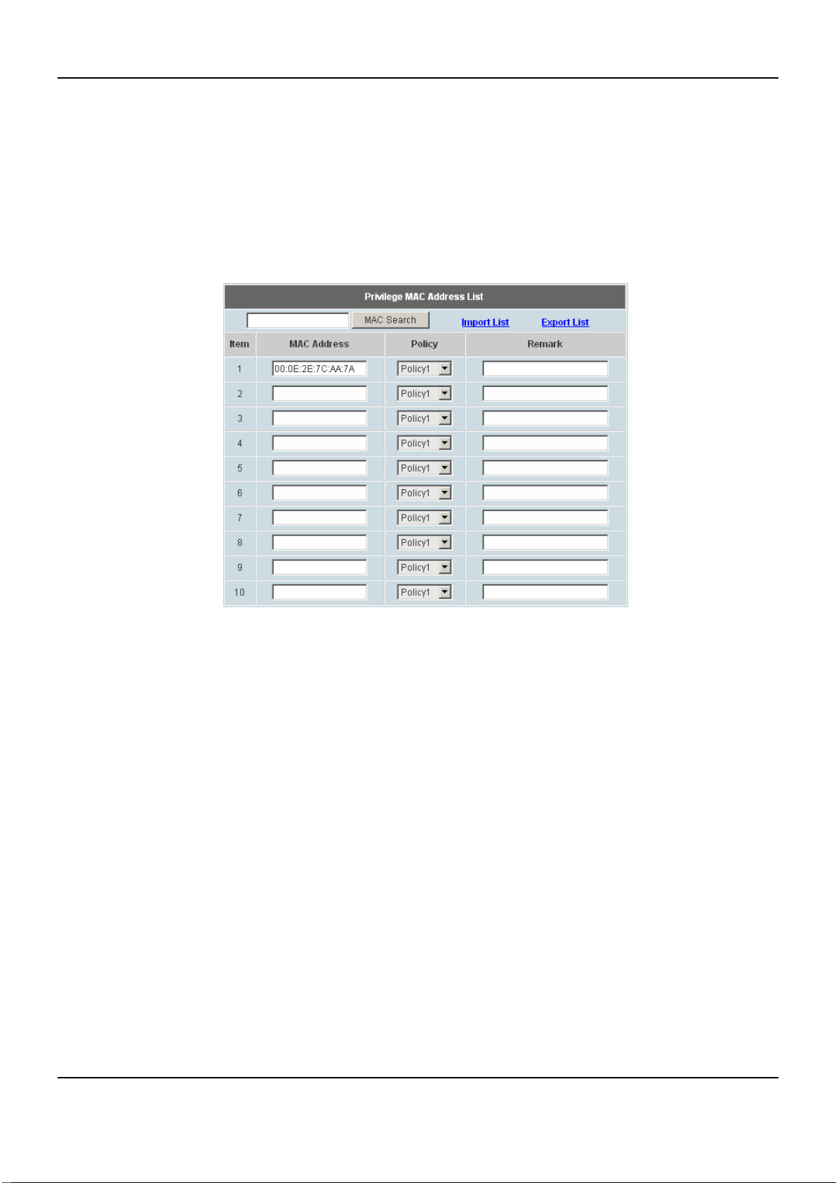
y Privilege MAC Address List
Clients with the MAC Address on the List are allowed to access the Internet directly; authentication is not
required. In addition to the IP address, the MAC address of the device that needs to access the network
without authentication can also be set in this list. The DSA-6100 allows up to 100 privilege MAC addresses.
The list can be created by entering data in the table or by import from a file. The list can be exported as well.
Be sure to enter the MAC address (the format is xx:xx:xx:xx:xx:xx) as well as the remark (optional) if manually
creating the list is desired, and select a policy for the individual entry. These settings will become effective
immediately after clicking Apply.
41
Page 48
DSA-6100 User Guide
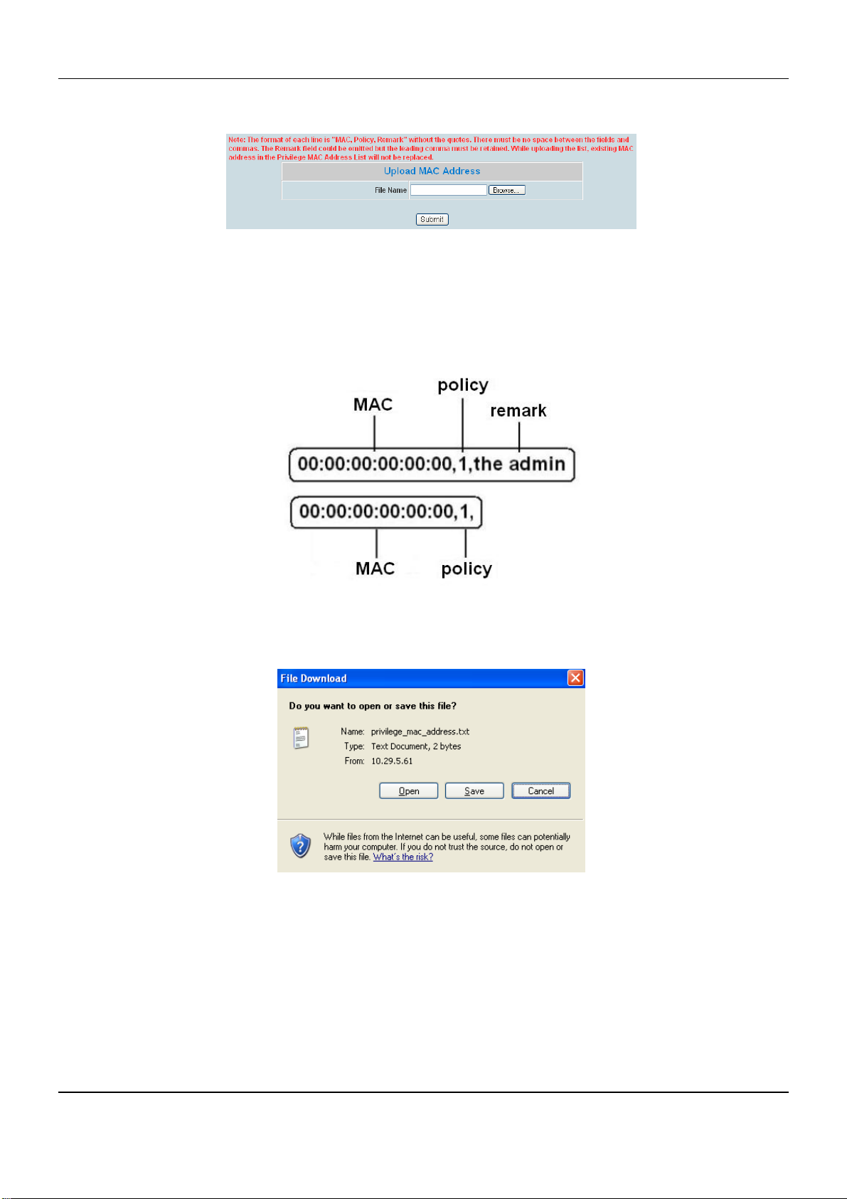
Import List: click Import List to enter the Upload MAC Address List interface. Click the Browse button to
select the text file for the user account upload. Then click Submit to complete the upload.
The uploading file should be a text file and the format of each line is " MAC, Policy, Remark" without the
quotes. There must be no spaces between the fields and commas. The remark field can be omitted but the
trailing comma must be retained. When adding user accounts by uploading a file, the existing accounts in the
embedded database will not be replaced by new ones.
Export List: Click Export List to export or create the Mac List into a .txt files and then save it on disk.
42
Page 49
Chapter 4. Web Interface Configuration
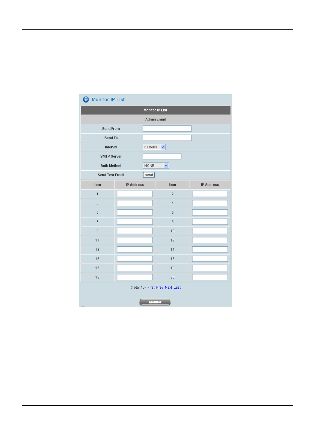
4.2.3 Monitor IP List
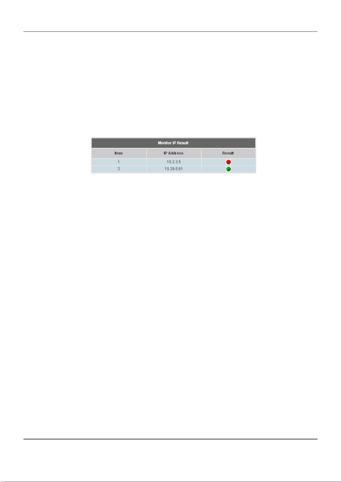
The system will send out a packet periodically to monitor the connection status of the IP addresses on the list. If the
monitored IP address does not respond, the system will send an e-mail to notify the administrator that such
destination is not reachable. After entering the related information, click Apply and these settings will become
effective immediately. Click Monitor to check the current status of all the monitored IP. The system provides up to
40 IP addresses for the “Monitor IP List”.
43
Page 50
DSA-6100 User Guide
y Send From: The e-mail address of the administrator in charge of the monitoring. This will show up as the
sender’s e-mail.
y Send To: The e-mail address of the person whom the monitoring result is for. This will be the receiver’s e-mail.
y Interval: The time interval to send the e-mail report.
y SMTP Server: The IP address of the SMTP server.
y Auth Method: The system provides four authentication methods, Plain, Login, CRAM-MD5 and NTLMv1, or
“None” to use none of the above. Depending on which authentication method selected, enter the Account
Name, Password and Domain.
y Send Test Email: Click Send to send out a test e-mail of the IP monitoring report.
y IP Address: The IP addresses under monitoring.
44
Page 51
Chapter 4. Web Interface Configuration
4.2.4 Walled Garden List
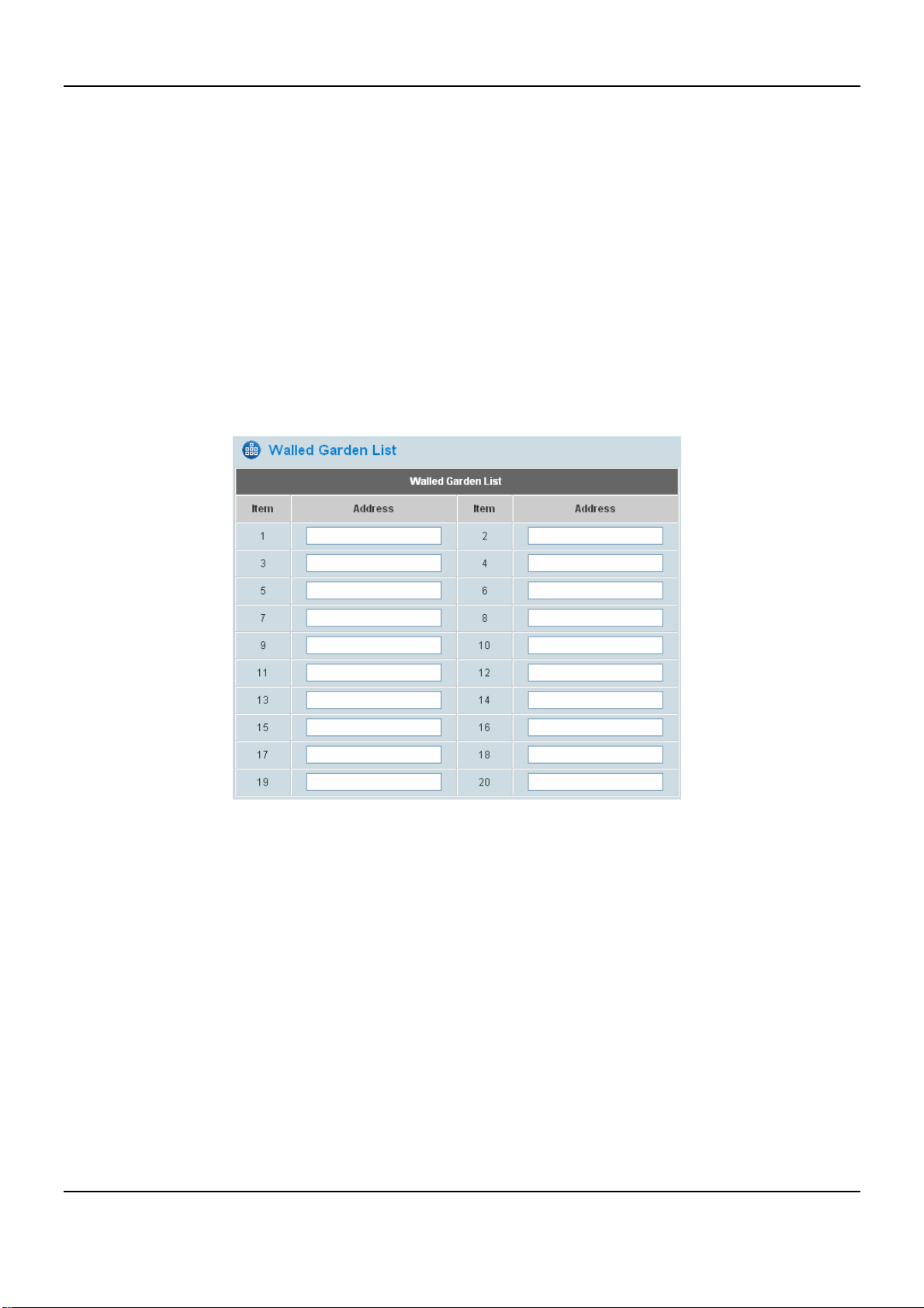
This system provides the free services to the users to access websites listed here before authentication. IP
addresses or domain names of the websites can be defined in this list. Users without the network access right can
still have a chance to experience the actual network service free of charge. This function allows clients of specified
addresses or domain names to access the Internet before login and authentication. Up to 20 addresses or domain
names of the websites can be defined in this list. Users without the network access right in the list can make use of
the actual network service free of charge.
Please enter IP Address or Domain Name of the website in the list. The settings will be effective immediately after
clicking Apply.
The Walled Garden supported by the system provides free surfing areas for clients to access before they are
authenticated by the system. An example may be seen in hotels, where guests without network access right are
allowed to utilize the network service free of charge such as accessing the Hotel’s homepage.
45
Page 52
DSA-6100 User Guide
4.2.5 Proxy Server Properties
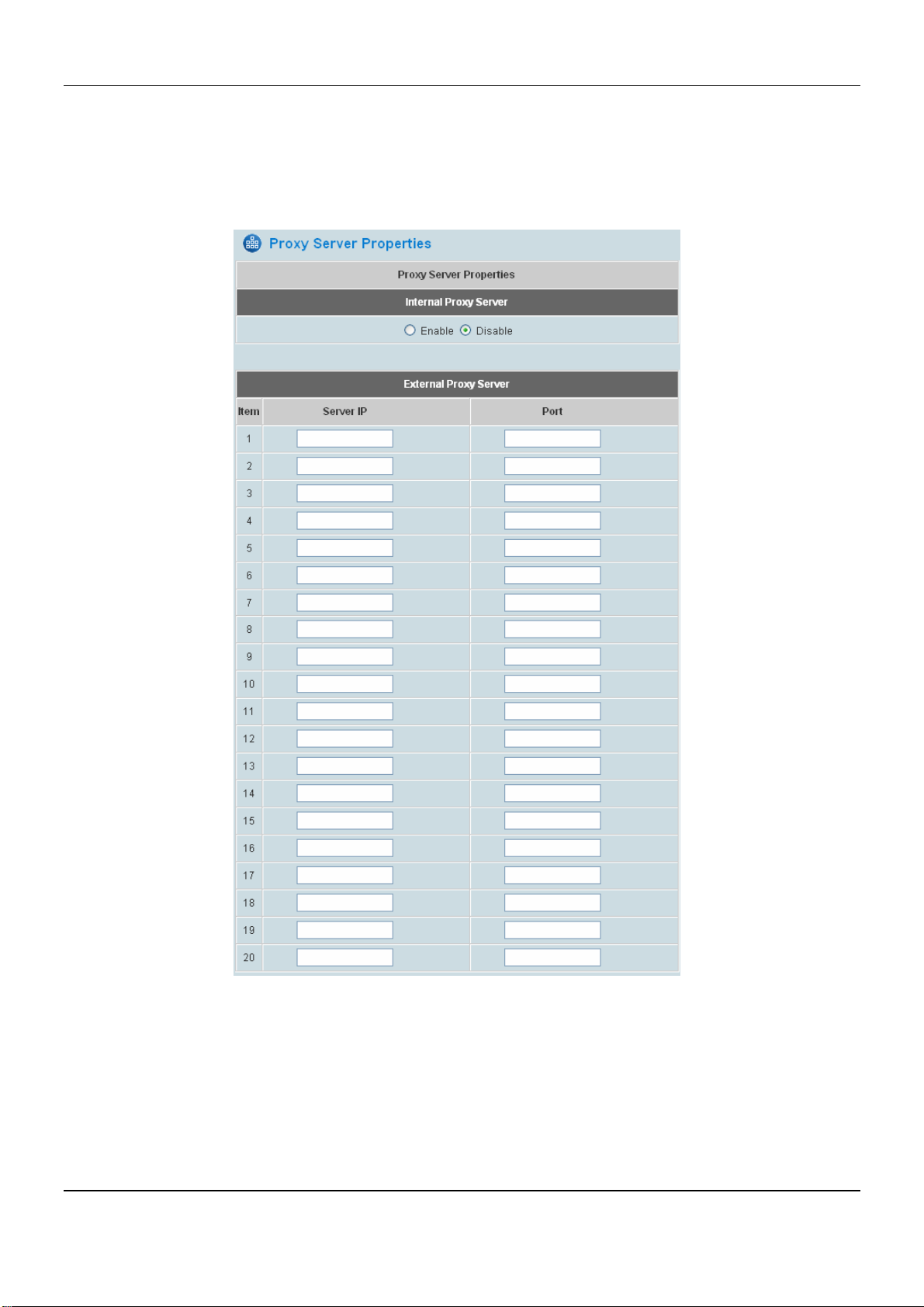
The DSA-6100 supports Internal Proxy Server and External Proxy Server functions. Please perform the necessary
configurations. Please click Apply and these settings will become effective immediately. For an example of Proxy
Configuration, please go to Appendix C. Proxy Configuration.
y Internal Proxy Server: The DSA-6100 has a built-in proxy server. If this function is enabled, the end users will
be forced to treat the DSA-6100 as the proxy server regardless of the end-users’ original proxy settings.
y External Proxy Server: Under the DSA-6100 security management, the system will match the External Proxy
Server list to the end-users’ proxy setting. If a match is not available, the end-users will not be able to reach the
login page and thus unable to access the network. If a match is available, the end-users will be directed to the
system first for authentication. After a successful authentication, the end-users will be redirected back to the
desired proxy servers depending on various situations.
46
Page 53
Chapter 4. Web Interface Configuration
4.2.6 Dynamic DNS
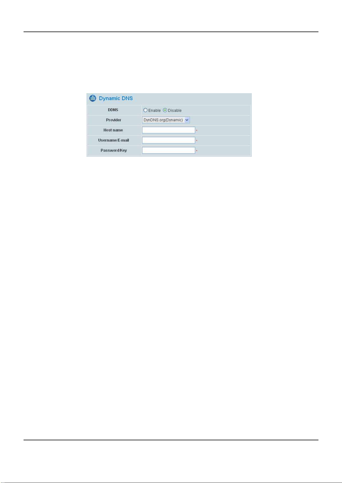
The DSA-6100 provides a convenient dynamic DNS (DDNS) function to translate the IP address of the WAN port
to a domain name that helps administrators easily memorize and connect to the WAN port. When the DHCP is
activated at WAN port, this function will also update the newest IP address regularly to the DNS server if the WAN1
interface is set to Dynamic. These settings will become effective immediately after clicking Apply.
y DDNS: Dynamic DNS, choose to enable or disable of this function.
y Provider: Select the dynamic DNS service provider.
y Host name: The IP address/domain name of the WAN port.
y Username/E-mail: The register ID (username or e-mail) for the dynamic DNS service provider.
y Password/Key: The register password for the dynamic service DNS provider.
Please click Apply and these settings will become effective immediately.
47
Page 54
DSA-6100 User Guide
4.2.7 IP Mobility
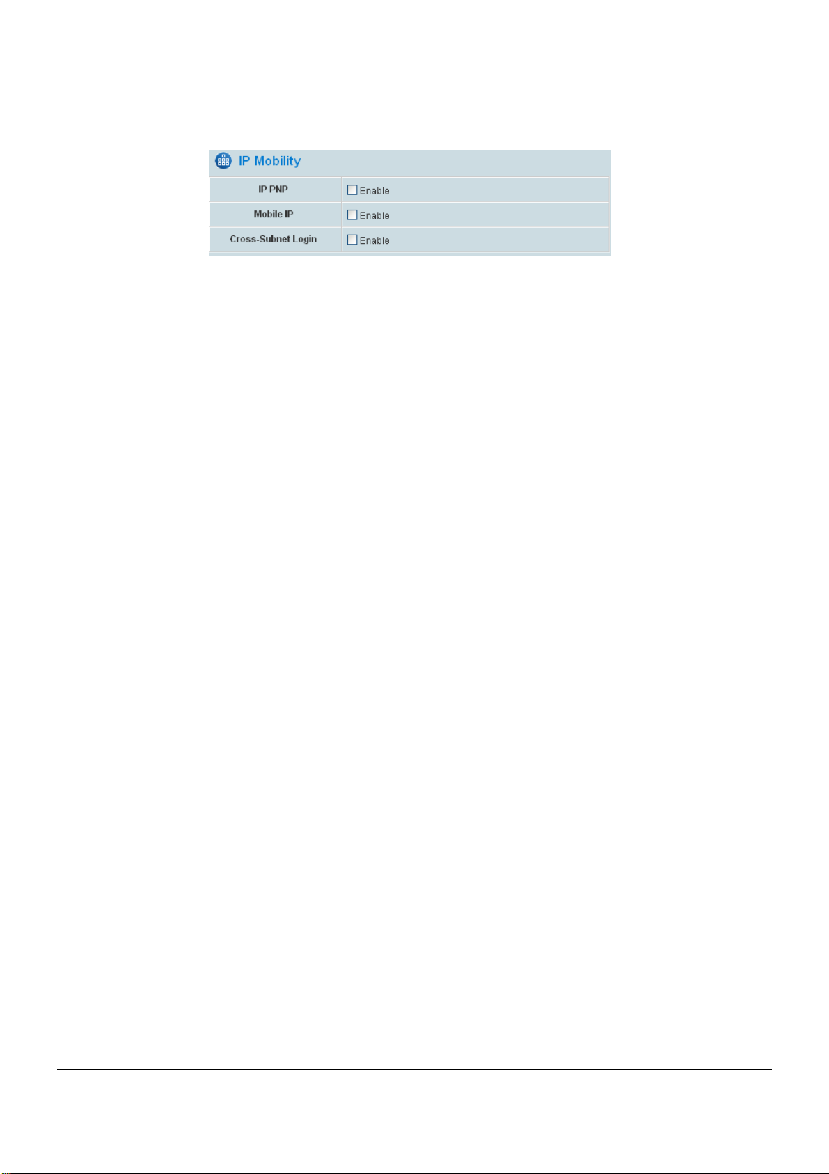
The DSA-6100 supports functions of IP PNP, Mobile IP and Cross-Subnet Login.
y Enable IP PNP
Allow or disallow users with wrong IP configuration. Clients can use any IP address to connect to the system.
Regardless of what the IP address at the client end is, he or she can still authenticate through the DSA-6100
and access the network.
y Enable Mobile IP
Allow or disallow users to move from one LAN segment to another without login again. When Mobil IP is
enabled, wireless clients roaming from two subnets behind the DSA-6100 with the same SSID will be able to
stay connected with the system, and disconnection will not occur. For example, when downloading data,
transmission will not be interrupted even while clients are roaming.
y Enable Cross-Subnet Login
If connecting a router between the LAN ports and the end computer (users, access points, etc), this function
must be enabled. Unlike bridge, switch, and hub, a router only use IP address to recognize source and
destination, thus by enabling this function, the DSA-6100 is able to use IP address as the only information to
process the request from the end computer.
48
Page 55
Chapter 4. Web Interface Configuration
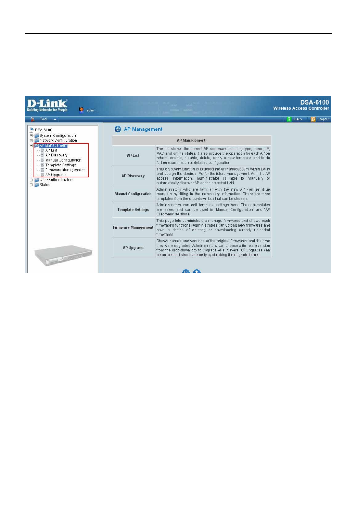
4.3 AP Management
This section includes the following functions: AP List, AP Discov ery, Manual Configuration, Template Settings,
Firmware Management and AP Upgrade.
49
Page 56
DSA-6100 User Guide
4.3.1 AP List
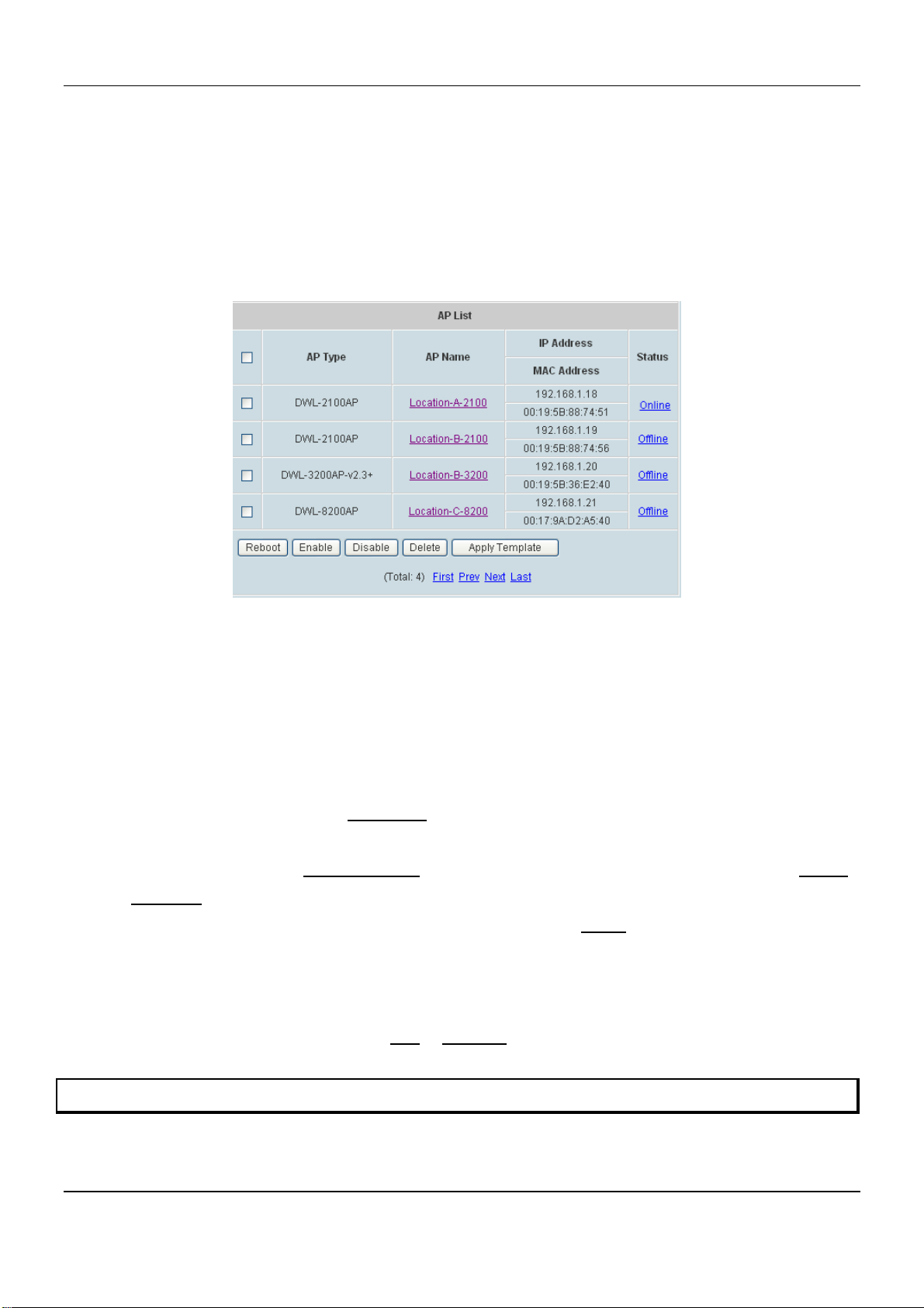
All of the managed APs will be shown in the list. The list is empty during first setup. To add APs to the list, the
administrator should first discover the manageable APs from AP Discovery or the Manual Configuration menu.
After the APs are added, this list will show the current status of all managed APs, including AP type, AP name, IP
Address, MAC Address, and Status. To perform functions for the specific APs on the list, select the check boxes of
the APs and click on Reboot, Enable, Disable, Delete or Apply Template.
y AP Type: This is the supported type of the AP for centralized management, including DWL-2100AP (v2.20eu,
v2.20na, v2.30eu, and v2.30na), DWL-3200AP (v2.30), DWL-8200AP (v1.20)
y AP Name: This is the mnemonic name of the AP. By clicking the hyperlink of AP Name, you can do further
configurations, including General Settings, LAN Interface Setting, Wireless Interface Setting and Access
Control Setting.
y Status: Current status of the AP, including Configuring, Online, Offline, Upgrading, and Lost/Unknown.
(1) Configuring: It is displayed as Configuring
being configured) or new setting is being applied to the AP.
(2) Online: The hyperlink of Online (Enabled)
(Disabled) indicates that the AP is currently online but not ready in service.
(3) Offline: The AP is currently offline; for example: it is displayed as Offline
for any reason.
(4) Upgrading: The AP is undergoing firmware upgrade.
(5) Lost/Unknown: After DSA-6100’s rebooting and before it tries to probe the AP and determine the exact
status, the status will be displayed as Lost
when the newly discovered AP is being added to the list (and
indicates that the AP is currently online and in service; Online
when the power of the AP is off
or Unknown temporarily.
Note: The supported types and firmware of APs are subject to change for different DSA-6100 firmware releases.
50
Page 57
Chapter 4. Web Interface Configuration
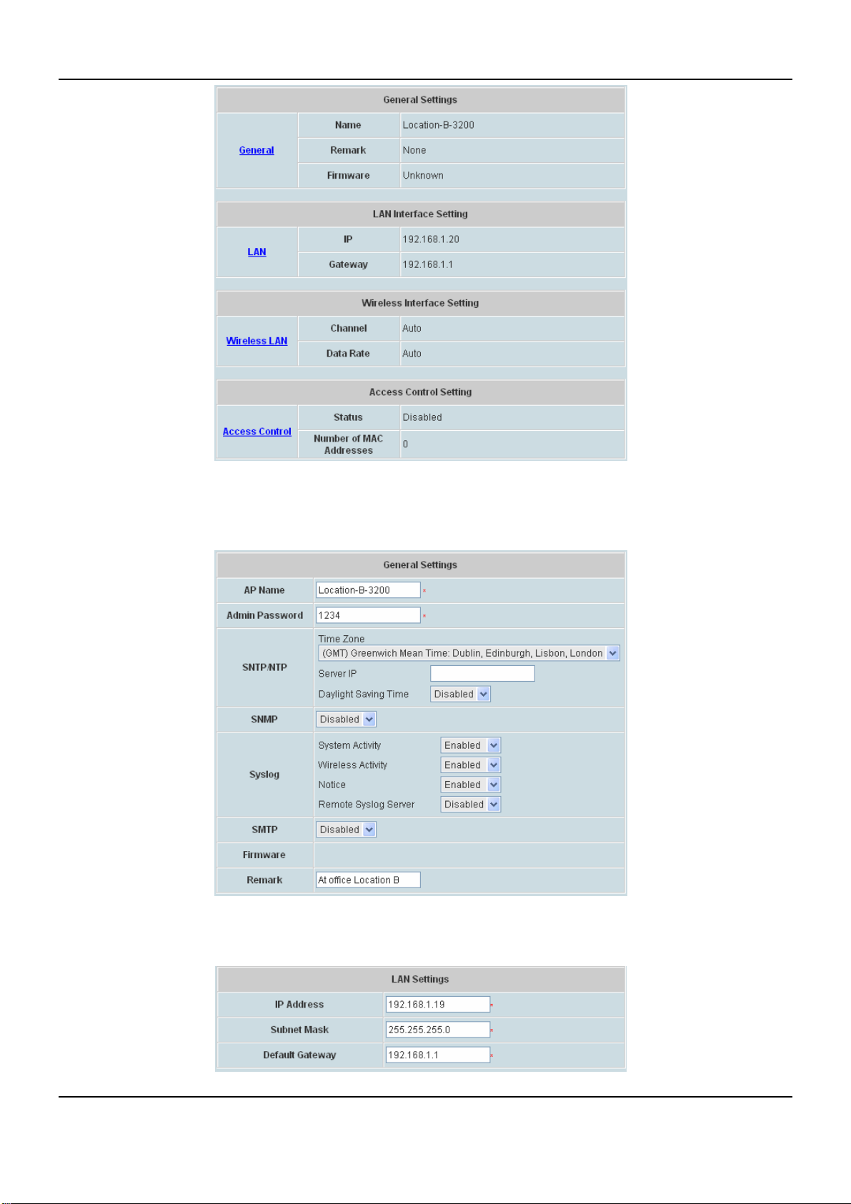
¾ General Settings: Click General to enter the General Settings interface. Revise the AP Name, Admin
Password, SNTP/NTP, SMTP, Syslog and Remark here if desired. Firmware information can also be
viewed here.
¾ LAN Interface Settings: Click LAN to enter the LAN Settings interface. Input the data of LAN including IP
Address, Subnet Mask and Default Gateway of AP.
51
Page 58
DSA-6100 User Guide
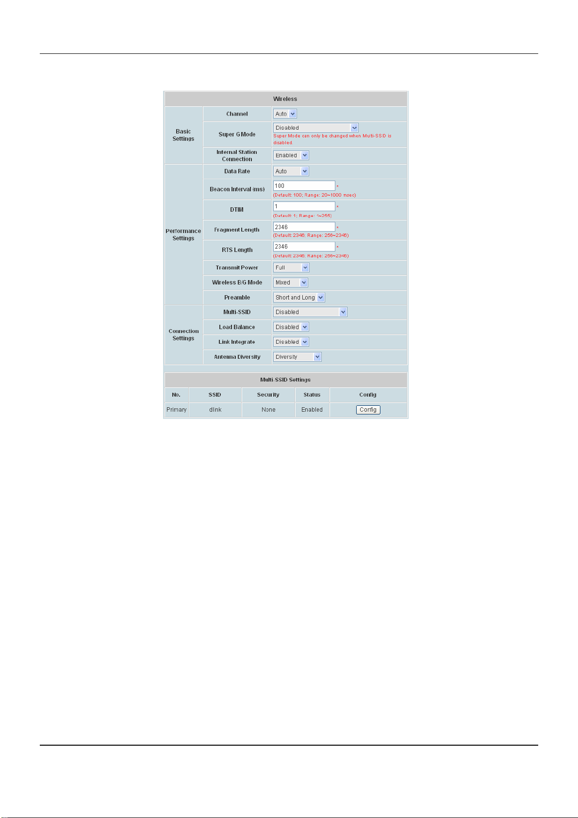
¾ Wireless Interface Setting: Click Wireless LAN to enter the Wireless interface. The data of Properties
and Security need to be filled.
Basic Settings:
y Channel: Select the appropriate channel from the list to correspond with the network settings; for
example, 1 to 11 channels are suitable for the North America area.
y Super Mode: Select either Disabled, Super Mode with Turbo or Super Mode without Turbo.
When Multi-SSID is selected as enabled, the item Super Mode cannot be active. Super G Mode can
only be changed when Multi-SSID is disabled.
y Internal Station Connection: Select either Enabled or Disabled. The connection allows clients to
communicate with each other when enabled.
Performance Settings
y Data Rate: The default is Auto. Available range is from 1 to 54Mbps. The rate of data transmission
should be set depending on the speed of the wireless network. Select from a range of transmission
speed or keep the default setting, Auto, to make the Access Point automatically use the fastest rate
possible.
y Beacon Interval (ms): Enter a value between 20 and 1000 msec. The default value is 100
milliseconds. The entered time means how often the beacon signal transmission between the access
point and the wireless network.
y DTIM: Delivery Traffic Indication Message. Enter a value between 1 and 255.
52
Page 59

Chapter 4. Web Interface Configuration
y Fragment Length : The fragmentation threshold determines whether packets will be fragmented. Enter
a value between 256 and 2346.
y RTS Length: Enter a value between 256 and 2346.
y Transmit Power: Select either Full, Half(-3dB), Quarter(-6dB), Eighth (-9dB) or Minimum (minimum
power).
y Wireless B/G mode: Enable supporting 802.11mixed mode 802.11b or 802.11g only.
y Preamble: The length of the CRC (Cyclic Redundancy Check) block for communication between the
Access Point and roaming wireless adapters. Select either Short Preamble or Long Preamble.
Connection Settings:
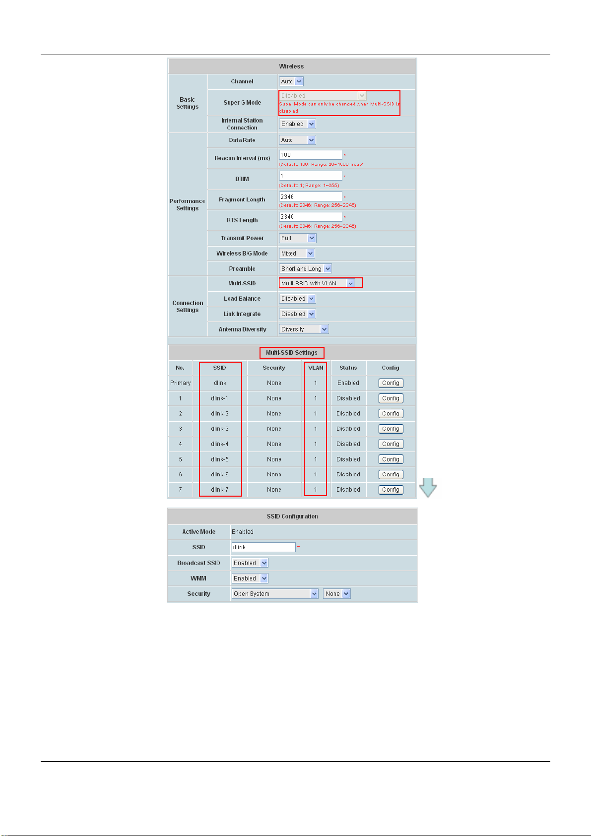
y Multi-SSID: Select Disabled, Multi-SSID with VLAN or Multi-SSID without VLAN. While Multi-SSID
enabled, Super G Mode will be disabled automatically. While selecting Multi-SSID with VLAN,
Multi-SSID settings could configure up to multiple SSID. Click Configure button to setup SSID
Configuration, the information of SSID, Broadcast SSID, WMM, and Security.
SSID Configuration Page:
¾ SSID: Service Set Identifier.
¾ Broadcast SSID: Select this option to enable the SSID to broadcast in your network. When
configuring the network, it is suggested to enable this function but disable it when the
configuration is complete. With this enabled, someone could easily obtain the SSID information
with the site survey software and get unauthorized access to a private network. With this
disabled, network security is enhanced and can prevent the SSID from being seen on
networked.
¾ WMM: WMM stands for Wi-Fi Multimedia, by enabling this feature. It will improve the user
experience for audio and video applications over a Wi-Fi network.
¾ Security: Choose one of security types from SSID Configuration, also selecting whether WEP
included or not.
53
Page 60
DSA-6100 User Guide
y Load Balance: When enabled, you allow several APs to balance wireless network traffic and wireless
clients among APs in the networks. Assign each access point a different non-overlapping channel.
¾ User Limit: Enter the number of the limit of load balancing users from 0~64.
y Link Integrate: Enable or disable the feature.
y Antenna Diversity : Choose from Diversity, Left Antenna or Right Antenna. Radio is connected to
each antenna and supports auto diversity mode by default. The access point will auto switch to the
antenna with better RSSI value.
54
Page 61
Chapter 4. Web Interface Configuration
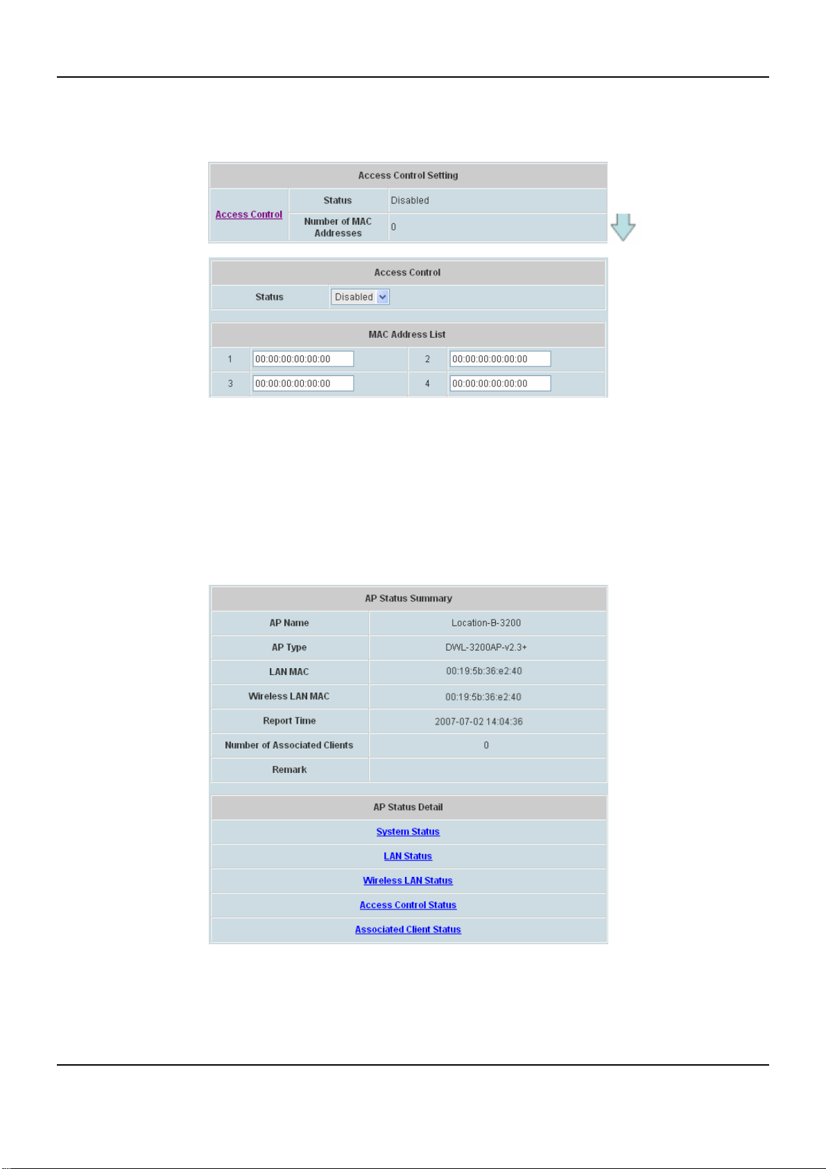
¾ Access Control Setting: In this function, when the status is Enabled, only these clients which MAC
addresses are listed in the list can be allowed to connect DSA-6100. When Disabled is selected, all
clients can connect DSA-6100. The default is Disabled.
y Status
After clicking the hyperlink in the Status column, there are two areas of information shown: AP Status
Summary and AP St atus Details. AP Status Summary includes AP Name, AP T ype, LAN interface MAC
address, Wireless interface MAC address, Report Time, Number of Associated Clients and Remark. AP
Status Details include System Status, LAN Sta tus, Wireless LAN Status, Access Control Status and
Associated Client Status.
y AP Name: Mnemonic name of the specified AP.
y AP Type: This is the supported type of APs for centralized management.
y LAN MA C: The LAN’s Media Access Control address.
y Wireless LA N MAC: The wireless LAN’s Media Access Control Address.
55
Page 62
DSA-6100 User Guide
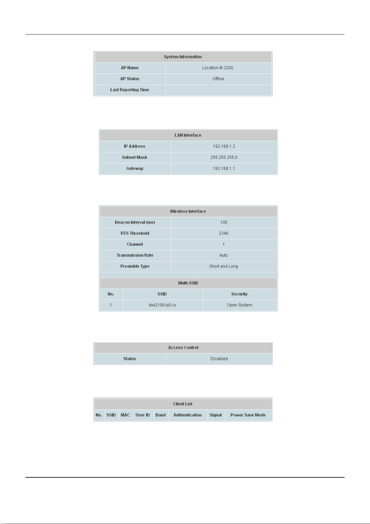
¾ System Status: The table shows the information about AP Name, AP Status and Last Reporting Time.
¾ LAN Status: The table shows the information about IP Address, Subnet Mask and Gateway.
¾ Wireless LAN Status: The table shows all of the related wireless information.
¾ Access Control Status: The table shows the lists of MAC of clients under the control of the AP.
¾ Associated Client Status: The table shows the clients connecting to the AP and the related information of
the client.
56
Page 63
Chapter 4. Web Interface Configuration
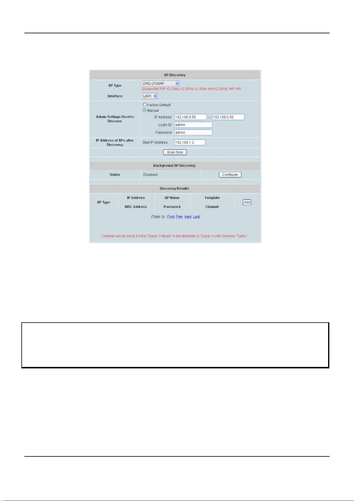
4.3.2 AP Discovery
Use this function to detect and manage all the supported APs in the network segments.
y AP Discovery Settings
When the administrator tries to discover a new AP, select Factory Default or Manual in Admin Settings Used
to Discover field; enter the current IP range of the APs if they are not in default value. Then click Scan Now
button. If the new AP has been discovered, it will appear in the following Discovery Results list. If there is a
warning message showing below the Discovery Settings, follow the instructions to change configurations.
Please fill in the required data.
Note: The APs (an d the firmware version as well as the hardware number) that are supported include:
1. DWL-2100 (FW v2.20/2.30eu and v2.20/2.30na;HW A4),
2. DWL-3200-v2.3+ (FW v2.30; HW B1)
3. DWL-8200 (FW v1.20; HW A2)
y To discover AP manually, please select/fill in the required data.
¾ AP Type: List the current AP types to choose from.
¾ Interface: Select between LAN ports where the APs are connected.
¾ Admin Settings Used to Discover: Select Manual, enter the current IP range of the APs in IP
Address field if they are not in default value. The IP of AP with factory default setting is "192.168.0.50".
If the AP was discovered before, the IP address of the AP should have been changed. Please enter the
right IP address of the AP or reset the AP to default values. Login ID is the admin ID of the AP. Password
57
Page 64
DSA-6100 User Guide
is the admin password of the AP. If the AP is in default value, just select Factory Default, system can
discovery the APs.
¾ IP Addresse s of APs after Discovery: The start IP to be assigned will be entered here.
¾ Scan Now: Click the Scan Now button and the APs that match the given settings will be shown in the
Discovered Results below. If any IP address among the IP range assigned for a specific AP is used,
there will be a warning message showing up. Please change the IP Addresses of APs af ter Discovery
and then click Scan Now again. For the desired AP, input the desired AP name and admin password,
select one template to apply, select the check box, and click Add to add the discovered AP to the List.
For more information about the template, please refer to 4.3.4 Templates.
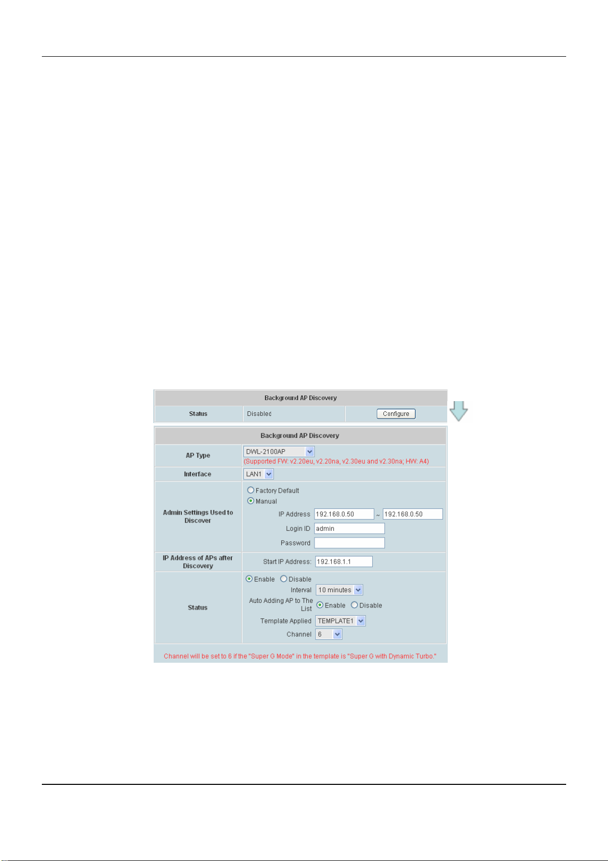
y Background AP Discovery
The system supports discovering APs periodically in background. The New IP Address Assignment and
Access to the AP Admin Interface configuration in Background Auto Discovery page are the same as in the
Discovery Settings. Click Configure and then select Enable to set the configuration. When Auto Adding AP to
the list is enabled, the system will add the discovered APs into the List table automatically and apply the
selected template in the Template Applied option to the AP. When the configurations are set as requirement,
the system will discover new APs periodically and automatically in background.
Click Configure to enter the Background AP Discovery page to have further configuration.
The Interface, Admin Settings Used to Discover and IP Addresses of APs after Discovery configurations
are the same as the settings mentioned above. Check Enable in the Status field to have more configuration.
Select Interval setting from the drop-down menu to set the system to scan periodically according to this setting
(the default value is 10 minutes). If Auto Adding AP to the list is enabled, a new detected AP will be assigned
an available IP address from the IP address range set in IP Addresses of APs after Discovery and applied
with the selected template automatically.
58
Page 65
Chapter 4. Web Interface Configuration
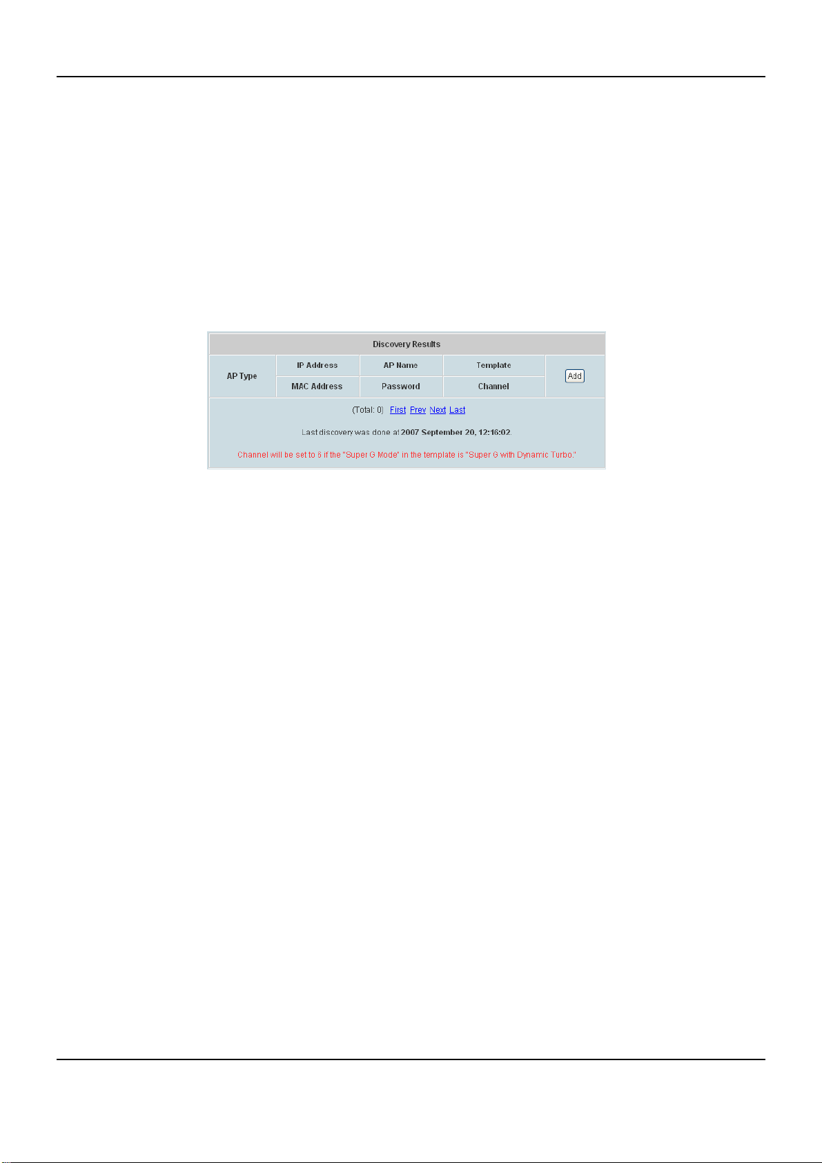
y Discovery Results
Then click the Scan Now button and the APs that match the given settings will show in the Discovery Results
below. If any IP address among the IP range assigned for a specific AP is used, there will be a warning
message showing up. For the desired AP, input the desired name and password, select one template to apply,
select the check box, and click Add to add the AP to the AP List. (About the template, please see 4.3.4
Template Settings).
When the matched AP is discovered, it will be shown in the AP List below and be given a new IP address as
set previously (ex: 192.168.2.2). Check the Add box to add the AP, and it will be listed in the AP List.
Click Configuring to go to the related configuration. For the details, please refer to 4.3.1 AP List.
59
Page 66
DSA-6100 User Guide
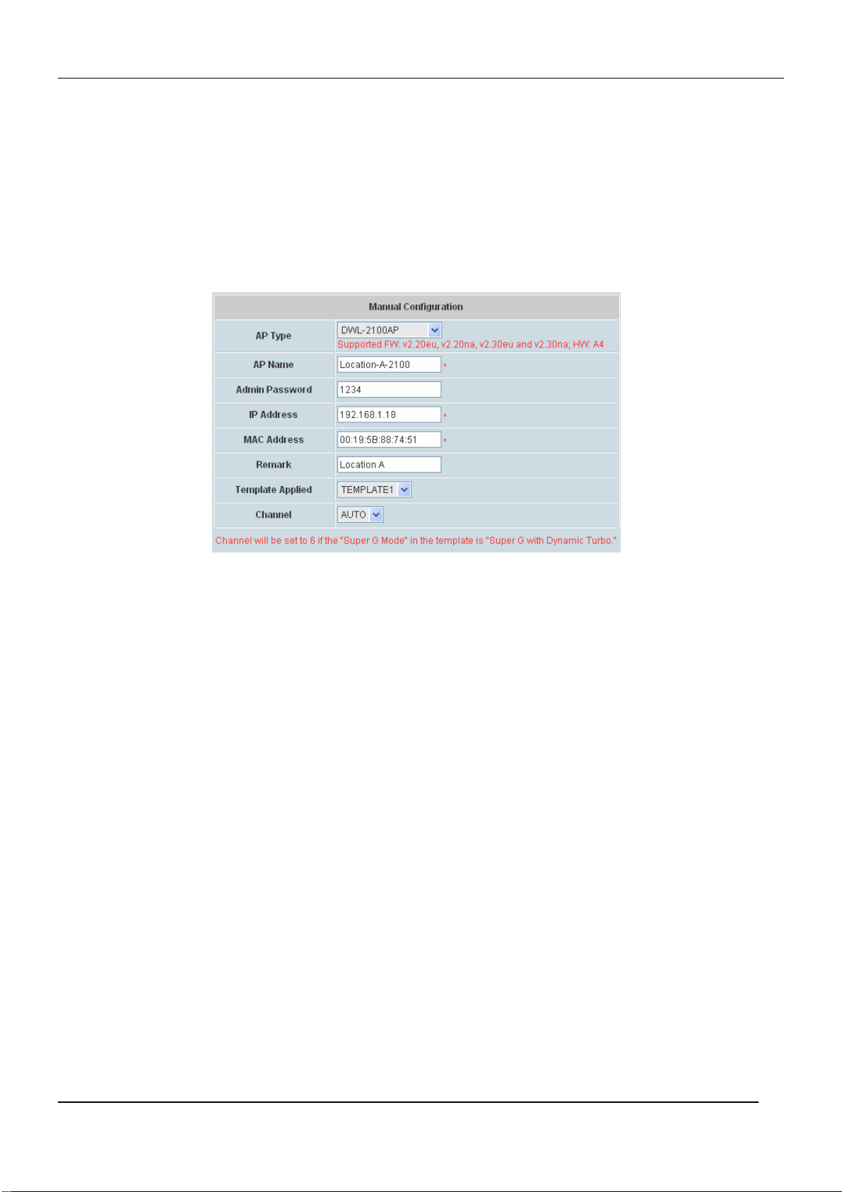
4.3.3 Manual Configuration
The administrators who choose to configure an AP manually can utilize this page, in which provides several fields
to be filled in. The supported APs (such as DWL-2100AP) can also be added manually. Enter the related
information of the AP and select a Template. Click Add and then the AP will be added to the List. Similar to the AP
added after discovery, a manually added AP will show up with a status of “configuring” in the AP List initially. The
system will attempt to configure the AP with the value specified. A couple of minutes later, the AP’s status will
become “online” or “offline” on the AP List.
y AP Type: The type of supported AP.
y AP Name: The mnemonic name of the specific AP.
y Admin Password: The password of the AP for the system to access it.
y IP Address: The IP address of the AP.
y MAC Addres s: The Media Access Control (MAC) address of the AP.
y Remark: The administrator can add some extra information for the AP in this field if desired.
y Template Applied: The template which will be applied to the AP.
y Channel: The RF channel to be used in the added AP.
60
Page 67
Chapter 4. Web Interface Configuration
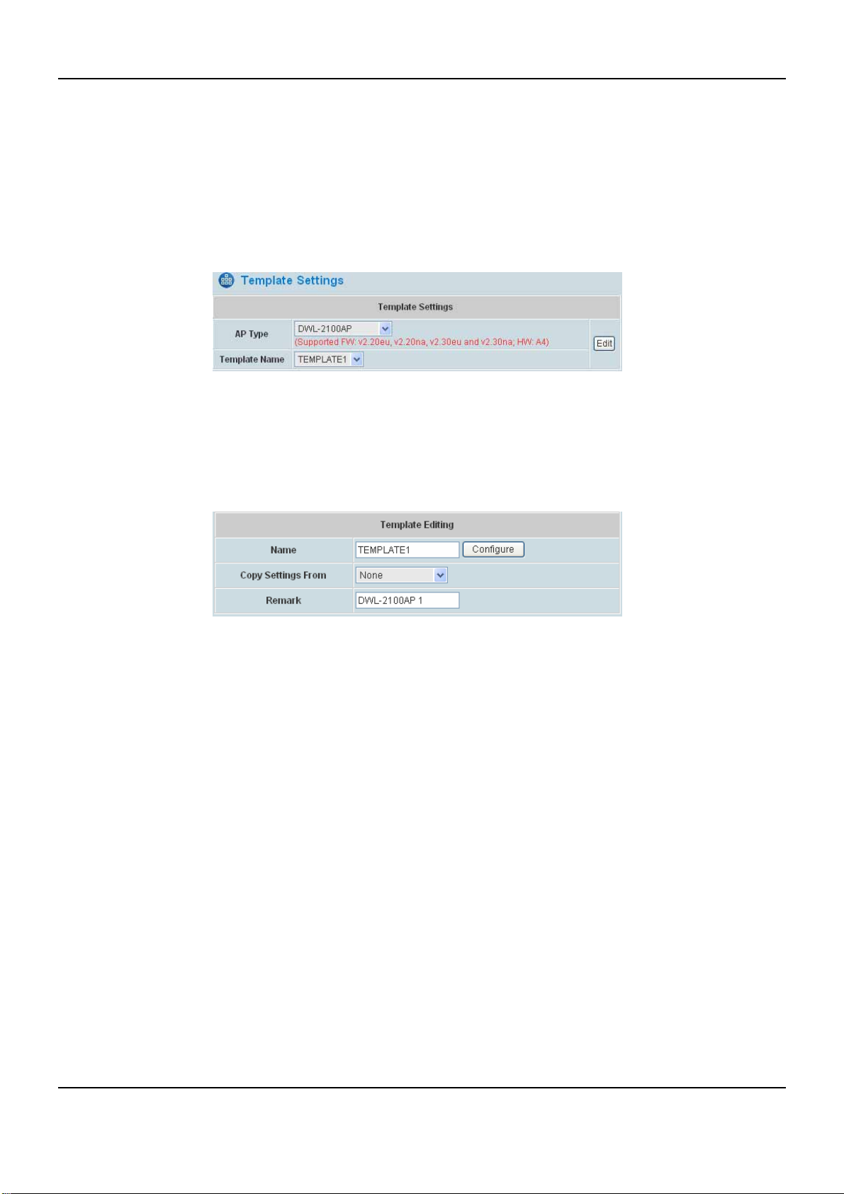
4.3.4 Template Settings
A template is a model that can be copied to every AP without having to configure the each AP individually. The
system supports up to three templates which include configurations of APs. The administrator can configure the
setting together in the template instead of logging the AP management interface to set the configurations one by
one. Click Edit to go to configuration. Select the AP type and one of the three available Template Name, and then
click Edit to have the Template Editing page.
Except configuring all the template setting manually, copy the configuration of an AP to the template by selecting a
Copy Settings From and revise some settings is also acceptable. Please select None if configuring the whole
template from the draft is desired. Enter the Name and Remark (optional) and click Configure to have further
configuration.
y Template Editing
The administrator can set the template configuration manually or copy the configurations from a specific
existing managed AP by Copy Settings From option. Click Configure button to have detailed configurations.
61
Page 68
DSA-6100 User Guide
I. DWL-2100AP
DWL-2100AP includes all standards 802.11b/g. The connection can be select to enable 802.11b/g or disable.
The DWL-2100AP is fully compatible with the IEEE 802.11b and 802.11g standards.
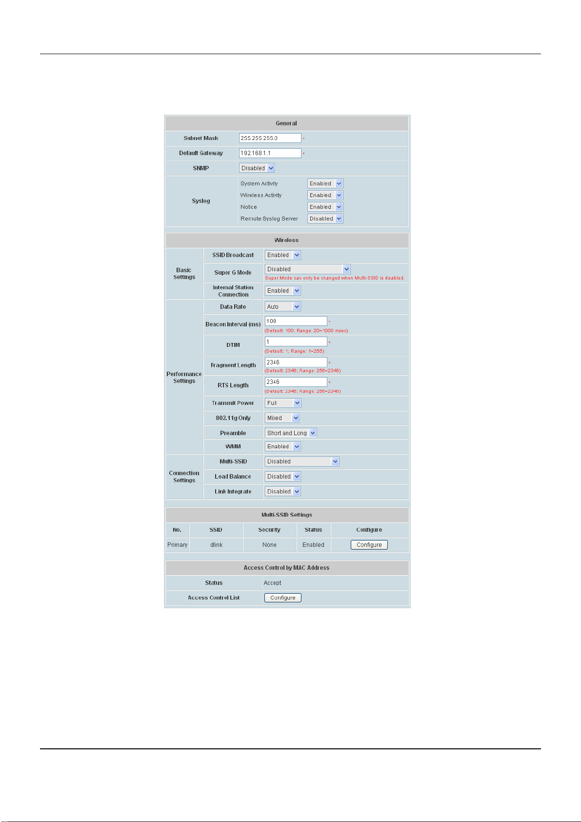
General
Subnet Mask: The default is 255.255.255.0. All devices in the network must share the same subnet mask.
Default Gateway: The default is 192.168.1.1. Enter the gateway IP address for the network, typically a router.
SNMP
¾ Public Community: When enabled, change the Public Community Name here.
¾ Private Community: When enabled, change the Private Community Name here.
¾ User Status Notification: Enable or Disable the feature.
62
Page 69

Chapter 4. Web Interface Configuration
Syslog
¾ System Activity: Select “Enable” to allow the logging of system actions, such as logging a firmware
upgrade.
¾ Wireless Activity: Select “Enable” to allow the logging of any wireless clients that connect to the AP.
¾ Notice: Select “Enable” to allow all other information to be logged.
¾ Remote Syslog Server: If you require more space to hold your logs, please provide the IP address of the
Server. The embedded memory can only have up to 300 logs.
Wireless
Basic Settings:
¾ SSID Broadcast: Select this option to enable the SSID to broadcast in your network. When configuring the
network, it is suggested to enable this function but disable it when the configuration is complete. With this
enabled, someone could easily obtain the SSID information with the site survey software and get
unauthorized access to a private network. With this disabled, network security is enhanced and can prevent
the SSID from being seen on networked.
¾ Super G Mode: Select either Disabled, Super G Mode with Turbo or Super G Mode without Turbo.
When Multi-SSID is selected as enabled, the item Super Mode cannot be active. Super G Mode can only
be changed when Multi-SSID is disabled.
¾ Internal Station Connection: Select either Enabled or Disabled. The connection allows clients to
communicate with each other when enabled. If this is disabled, wireless stations of the selected band are
not allowed to exchange data through the access point.
Performance Settings:
¾ Data Rate: The default is Auto. Available range is from 1 to 54Mbps. The rate of data transmission should
be set depending on the speed of the wireless network. Select from a range of transmission speed or keep
the default setting, Auto, to make the Access Point automatically use the fastest rate possible.
¾ Beacon Interval (ms): Enter a value between 20 and 1000 msec. The default value is 100 milliseconds.
The entered time means how often the beacon signal transmission between the access point and the
wireless network.
¾ DTIM: Delivery Traffic Indication Message. Enter a value between 1 and 255. DTIM is a countdown
informing clients of the next window for listening to broadcast and multicast messages.
¾ Fragment Length: The fragmentation threshold determines whether packets will be fragmented. Enter a
value between 256 and 2346.
¾ RTS Length: Enter a value between 256 and 2346. When wireless clients would like to send a packet
which is larger than this value, it transmits an RTS and waits for reply.
¾
Transmit Power: Select either Full, Half(-3dB), Quarter(-6dB), Eighth (-9dB) or Minimum (minimum
power).
¾ 802.11g Only: The function allows you to configure the wireless network with IEEE 802.11g only, Mixed.
¾ Preamble: Select Long Only or Short and Long. A short preamble is recommended for high-traffic
63
Page 70
DSA-6100 User Guide
networks.
¾ WMM: WMM stands for Wi-Fi Multimedia, by enabling this feature. It will improve the user experience for
audio and video applications over a Wi-Fi network.
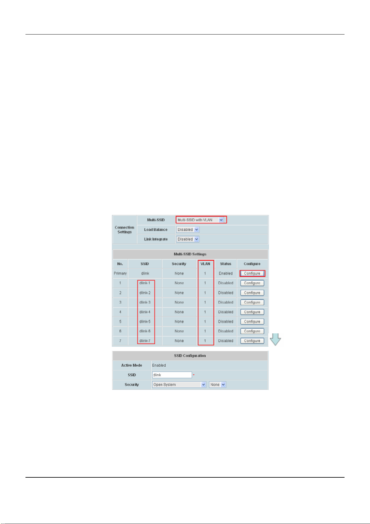
Connection Settings:
¾ Multi-SSID: Multiple Service Set Identifier. Select either Disabled, Multi-SSID with VLAN or Multi-SSID
without VLAN.
¾ Load Balance: When enabled, you allow several APs to balance wireless network traffic and wireless
clients among APs in the networks. Assign each access point a different non-overlapping channel.
o User Limit: Enter the number of the limit of load balancing users from 0~64.
¾ Link Integrate: Enable or disable the feature.
Multi-SSID Settings: Select Disabled, Multi-SSID with VLAN or Multi-SSID without VLAN. While
Multi-SSID enabled, Super G Mode will be disabled automatically. While selecting Multi-SSID with VLAN,
Multi-SSID settings could configure up to multiple SSID. Click Configure button to setup SSID Configuration,
the information of SSID and Security.
○ SSID Configuration Page:
¾ SSID: Service Set Identifier.
¾ Security: Choose one of security types from SSID Configuration, also selecting whether WEP
included or not.
64
Page 71
Chapter 4. Web Interface Configuration
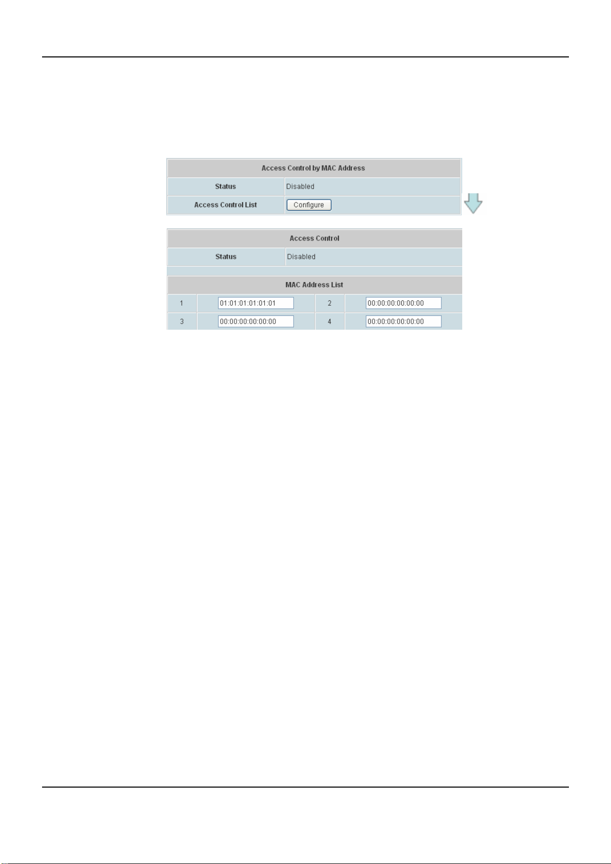
Access Control by MAC Address: MAC address based control for access the network (AP). This function
provides to control the clients’ devices that are allowed to associate with the APs applied with the desired
template setting. Choose Disabled or Enabled in the Status column and enter the desired clients’ MAC
addresses in the MAC Address List. When this function is enabled, please make sure the MAC Address List is
not empty.
65
Page 72
DSA-6100 User Guide
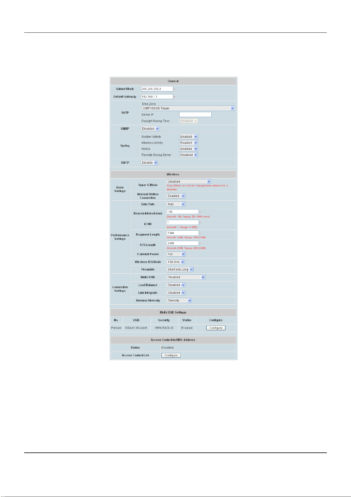
II. DWL-3200AP-v2.3+
DWL-3200AP version 2.3 Templates settings allow users to configure wireless 802.11b/g mode settings.
DWL-3200AP includes all three standards 802.11b/g mixed, 802.11b only and 802.11g only. Firmware upgrade
from DWL-3200AP v2.20 to v2.3 is NOT supported by the system.
General
Subnet Mask: The default is 255.255.255.0. All devices in the network must share the same subnet mask.
Default Gateway: The default is 192.168.1.1. Enter the gateway IP address for the network, typically a router.
SNTP/NTP: The time server IP address, time zone, and the local time will be displayed.
¾ Time Zone: Select your time zone from the drop-down menu.
¾ Server IP: Enter the IP address of a SNTP/NTP server.
¾ Daylight Saving Time: Check the box to enable daylight saving time.
SNMP
66
Page 73

Chapter 4. Web Interface Configuration
¾ Public Community: When enabled, change the Public Community Name here.
¾ Private Community: When enabled, change the Private Community Name here.
Syslog
¾ System Activity: Select “Enable” to allow the logging of system actions, such as logging a firmware
upgrade.
¾ Wireless Activity: Select “Enable” to allow the logging of any wireless clients that connect to the AP.
¾ Notice: Select “Enable” to allow all other information to be logged.
¾ Remote Syslog Server: If you require more space to hold your logs, please provide the IP address of the
Server. The embedded memory can only have up to 300 logs.
SMTP
¾ SMTP Server IP: IP address of SMTP Server
¾ SMTP Sender: The sender’s Email address
¾ SMTP Recipient: The receiver’s Email address
Wireless
Basic Settings:
¾ Super G Mode: Select either Disabled, Super G Mode with Turbo or Super G Mode without Turbo.
When Multi-SSID is selected as enabled, the item Super Mode cannot be active. Super G Mode can only
be changed when Multi-SSID is disabled
¾ Internal Station Connection: Select either Enabled or Disabled. The connection allows clients to
communicate with each other when enabled.
Performance Settings:
¾ Data Rate: The default is Auto. Available range is from 1 to 54Mbps. The rate of data transmission should
be set depending on the speed of the wireless network. Select from a range of transmission speed or
keep the default setting, Auto, to make the Access Point automatically use the fastest rate possible.
¾ Beacon Interval (ms): Enter a value between 20 and 1000 msec. The default value is 100 milliseconds.
The entered time means how often the beacon signal transmission between the access point and the
wireless network.
¾ DTIM: Delivery Traffic Indication Message. Enter a value between 1 and 255. DTIM is a countdown
informing clients of the next window for listening to broadcast and multicast messages.
¾
Fragment Length: The fragmentation threshold determines whether packets will be fragmented. Enter a
value between 256 and 2346.
¾ RTS Length: Enter a value between 256 and 2346. When wireless clients would like to send a packet
which is larger than this value, it transmits an RTS and waits for reply.
¾ Transmit Power: Select either Full, Half(-3dB), Quarter(-6dB), Eighth (-9dB) or Minimum (minimum
power). This tool can be helpful for security purpose if you wish to limit the transmission range.
¾ Wireless B/G mode: Choose between Mixed, 11b only or 11g only. The function allows you to configure
the wireless network with IEEE 802.11g only, IEEE 802.11b only, or IEEE 802.11g with backward
67
Page 74

DSA-6100 User Guide
interoperability with IEEE 802.11b.
o Mixed: Select when using 802.11b and 802.11g wireless device.
o 802.11g Only: Select when using all 802.11g wireless device.
o 802.11b Only: Select when using all 802.11b wireless device.
¾ Preamble: Select Long Only or Short and Long. A short preamble is recommended for high-traffic
networks.
Connection Settings:
¾ Multi-SSID: Multiple Service Set Identifier. Select either Disabled, Multi-SSID with VLAN or
Multi-SSID without VLAN.
¾ Load Balance: When enabled, you allow several APs to balance wireless network traffic and
wireless clients among APs in the networks. Assign each access point a different non-overlapping
channel.
o User Limit: Enter the number of the limit of load balancing users from 0~64.
¾ Link Integrate: Disable or Enable this feature.
¾ Antenna Diversity: Radio is connected to each antenna and supports auto diversity mode by
default. The access point will auto switch to the antenna with better RSSI value.
o Diversity: The AP will auto switch to the antenna with better RSSI value.
o Left Antenna: The AP will not switch antenna and the radio will use the left antenna to transmit
and receive packets.
o Right Antenna: AP won’t switch antenna and the radio will use the right antenna to transmit and
receive packets.
Multi-SSID Settings: Select Disabled, Multi-SSID with VLAN or Multi-SSID without VLAN. While
Multi-SSID enabled, Super G Mode will be disabled automatically. While selecting Multi-SSID with VLAN,
Multi-SSID settings could configure up to multiple SSID. Click Configure button to setup SSID Configuration,
the information of SSID, Broadcast SSID, WMM and Security.
68
Page 75
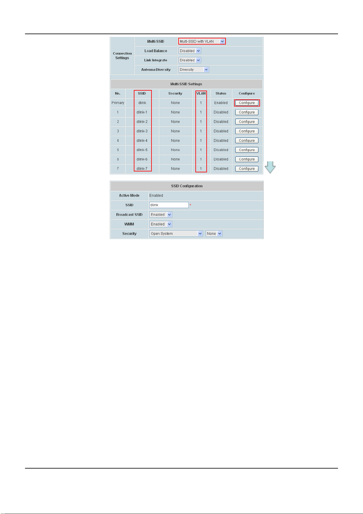
Chapter 4. Web Interface Configuration
○ SSID Configuration Page:
¾ SSID: Service Set Identifier.
¾ Broadcast SSID: Select this option to enable the SSID to broadcast in your network. When
configuring the network, it is suggested to enable this function but disable it when the configuration is
complete. With this enabled, someone could easily obtain the SSID information with the site survey
software and get unauthorized access to a private network. With this disabled, network security is
enhanced and can prevent the SSID from being seen on networked.
¾ WMM: WMM stands for Wi-Fi Multimedia, by enabling this feature. It will improve the user
experience for audio and video applications over a Wi-Fi network.
¾ Security: Choose one of security types from SSID Configuration, also selecting whether WEP
included or not.
69
Page 76
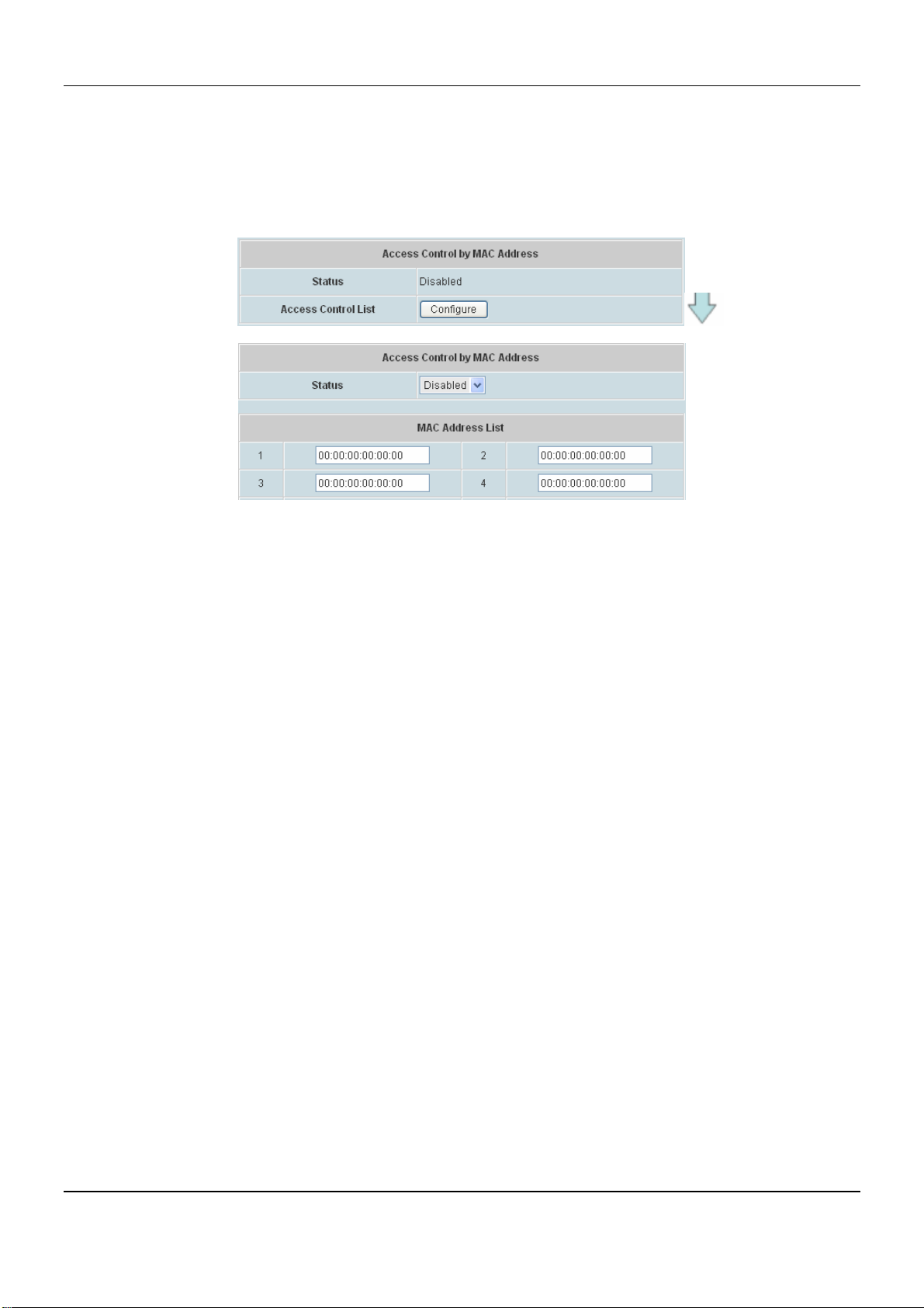
DSA-6100 User Guide
Access Control by MAC Address : MAC address based control for access the network (AP). This function
provides to control the clients’ devices that are allowed to associate with the APs applied with the desired
template setting. Choose Disabled or Enabled in the Status column and enter the desired clients’ MAC
addresses in the MAC Address List. When this function is enabled, please make sure the MAC Address List
is not empty.
70
Page 77
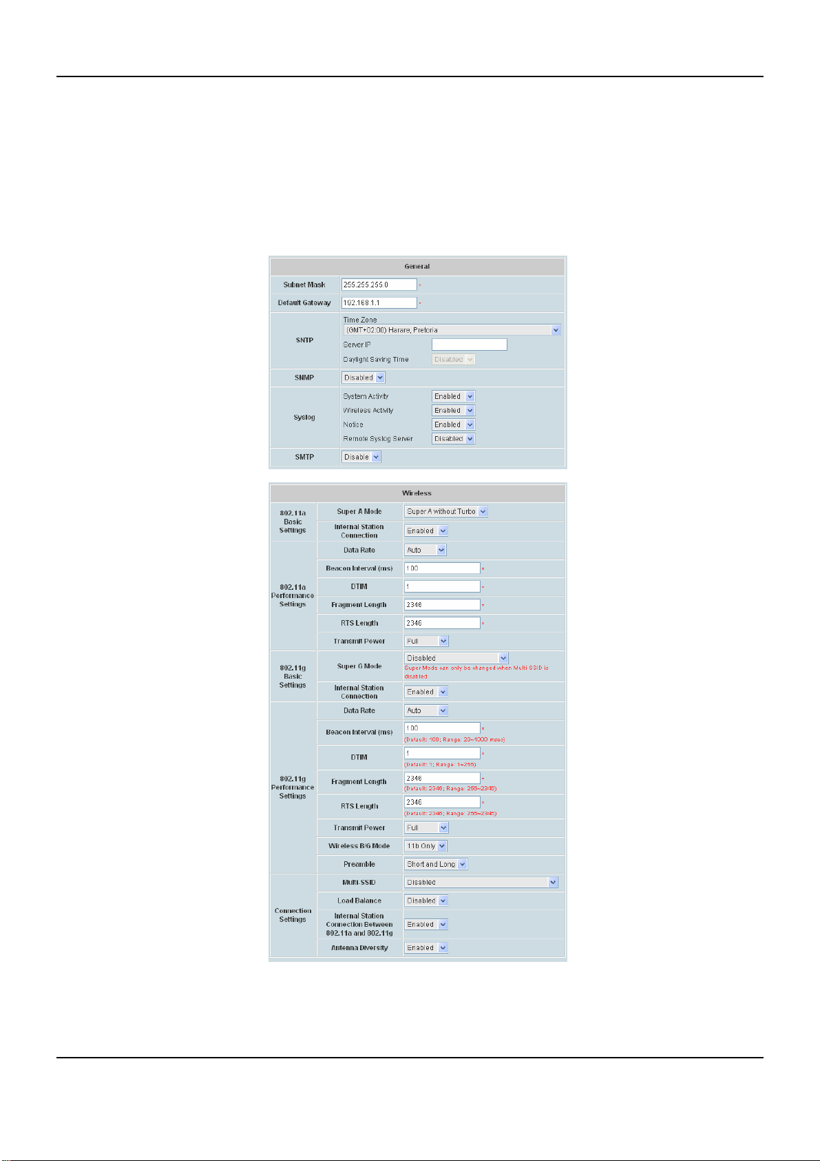
Chapter 4. Web Interface Configuration
III. DWL-8200AP
DWL-8200AP includes all three standards 802.11a, 802.11b and 802.11g. DWL-8200AP Templates settings
allows users to configure 802.11a and 802.11b and g mode settings. The connection could be select to enable
802.11a, 802.11b/g, or disable. Compatible with 802.11a, 802.11b and 802.11g Devices that is fully compatible
with the IEEE 802.11a, 802.11b and 802.11g standards, the DWL-8200AP can connect with existing 802.11b-,
802.11g- or 802.11a-compliant wireless network adapter cards. It is compatible with the 802.11b standard to
provide a wireless data rate of up to 11Mbps.
71
Page 78
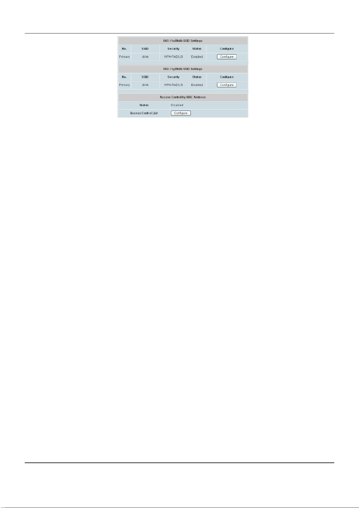
DSA-6100 User Guide
General
Subnet Mask: The default is 255.255.255.0. All devices in the network must share the same subnet mask.
Default Gateway: The default is 192.168.1.1. Enter the gateway IP address for the network, typically a router.
SNTP/NTP: The time server IP address, time zone, and the local time will be displayed.
¾ Time Zone: Select your time zone from the drop-down menu.
¾ Server IP: Enter the IP address of a SNTP/NTP server.
¾ Daylight Saving Time: Check the box to enable daylight saving time.
SNMP
¾ Public Community: When enabled, change the Public Community Name here.
¾ Private Community: When enabled, change the Private Community Name here.
Syslog
¾ System Activity: Select “Enable” to allow the logging of system actions, such as logging a firmware
upgrade.
¾ Wireless Activity: Select “Enable” to allow the logging of any wireless clients that connect to the AP.
¾ Notice: Select “Enable” to allow all other information to be logged.
¾ Remote Syslog Server: If you require more space to hold your logs, please provide the IP address of the
Server. The embedded memory can only have up to 300 logs.
SMTP
¾ SMTP Server IP: IP address of SMTP Server
¾ SMTP Sender: The sender’s Email address
¾ SMTP Recipient: The receiver’s Email address
Wireless
802.11a Basic Settings / 802.11g Basic Settings:
¾ Super Mode A/G Mode: Select either Disabled, Super A without Turbo, Super G without Turbo or
Super G with Dynamic Turbo. When Multi-SSID is selected as enabled, the item Super Mode cannot be
active. Super G Mode can only be changed when Multi-SSID is disabled.
o Disabled: Standard 802.11a/g support, no enhanced capability.
o
Super A/G without Turbo: Capable of Packet Bursting, FastFrames, Compression, and no Turbo
mode.
o Super G with Dynamic Turbo: Dynamic Turbo Mode is only enabled when all devices on the wireless
72
Page 79

Chapter 4. Web Interface Configuration
network are configured with Super Mode with Dynamic Turbo enabled.
¾ Internal Station Connection: Select either Enabled or Disabled. The connection allows clients to
communicate with each other when enabled.
802.11a Performance Settings/ 802.11g Performance Settings:
¾ Data Rate: The default is Auto. Available range is from 1 to 54Mbps. The rate of data transmission should
be set depending on the speed of the wireless network. Select from a range of transmission speed or keep
the default setting, Auto, to make the Access Point automatically use the fastest rate possible.
¾ Beacon Interval (ms): Enter a value between 20 and 1000 msec. The default value is 100 milliseconds.
The entered time means how often the beacon signal transmission between the access point and the
wireless network.
¾ DTIM: Delivery Traffic Indication Message. Enter a value between 1 and 255. DTIM is a countdown
informing clients of the next window for listening to broadcast and multicast messages.
¾ Fragment Length: The fragmentation threshold determines whether packets will be fragmented. Enter a
value between 256 and 2346.
¾ RTS Length: Enter a value between 256 and 2346. When wireless clients would like to send a packet
which is larger than this value, it transmits an RTS and waits for reply.
¾ Transmit Power: Select either Full, Half(-3dB), Quarter(-6dB), Eighth (-9dB) or Minimum (minimum power).
This tool can be helpful for security purpose if you wish to limit the transmission range.
¾ Wireless B/G mode: Choose between Mixed, 11b only or 11g only. The function allows you to configure
the wireless network with IEEE 802.11g only, IEEE 802.11b only, or IEEE 802.11g with backward
interoperability with IEEE 802.11b.
o Mixed: Select when using 802.11b and 802.11g wireless device.
o 802.11g Only: Select when using all 802.11g wireless device.
o 802.11b Only: Select when using all 802.11b wireless device.
¾ Preamble: Select Long Only or Short and Long. A short preamble is recommended for high-traffic
networks.
Connection Settings:
¾ Multi-SSID: Multiple Service Set Identifier. Select either Disabled, Multi-SSID without VLAN 802.11g
mode only, Multi-SSID without VLAN 802.11b mode only, Multi-SSID without VLAN for both modes or
Multi-SSID with VLAN.
¾ Load Balance: Select either Enabled
or Disabled. When enabled, you allow several APs to balance
wireless network traffic and wireless clients among APs in the networks. Assign each access point a
different non-overlapping channel.
o User Limit: Enter the number of the limit of load balancing users from 0~64.
¾ Internal Station Connection Between 802.11a and 802.11g: Select Enabled or Disabled the connection
feature.
¾ Antenna Diversity: When enabled, each radio will automatically switch to the antenna with the greatest
73
Page 80
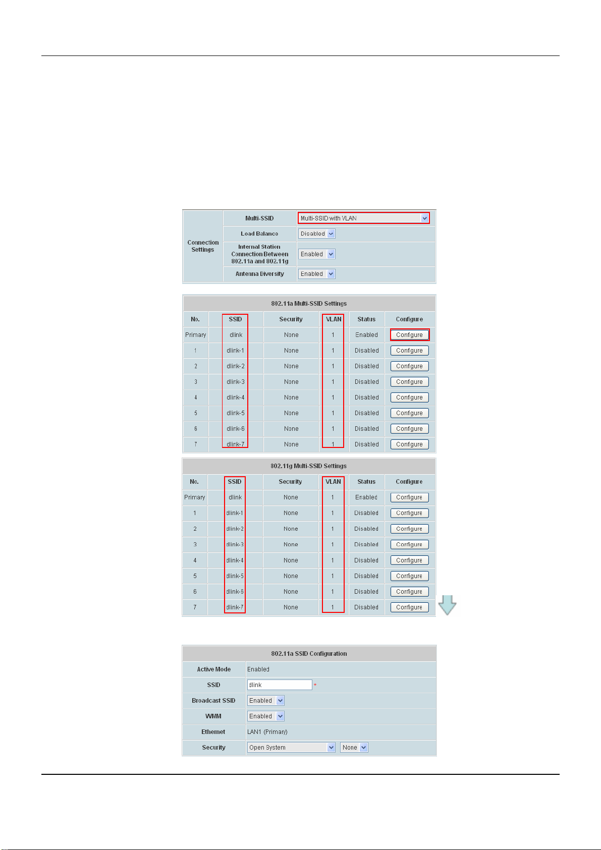
DSA-6100 User Guide
RSSI value. When disabled, each radio will use its main antenna.
802.11g Multi-SSID Settings /802.11a Multi-SSID Settings: Select Disabled, Multi-SSID without VLAN
802.11g mode only, Multi-SSID without VLAN 802.11b mode only, Multi-SSID without VLAN for both
modes or Multi-SSID with VLAN. While Multi-SSID enabled, Super G / A Mode will be disabled automatically.
While selecting Multi-SSID with VLAN, Multi-SSID settings could configure up to multiple SSID. Click
Configure button to setup SSID Configuration, the information of SSID, Broadcast SSID, WMM and
Security.
Click button of Configure to further setup Multi-SSID Settings.
74
Page 81
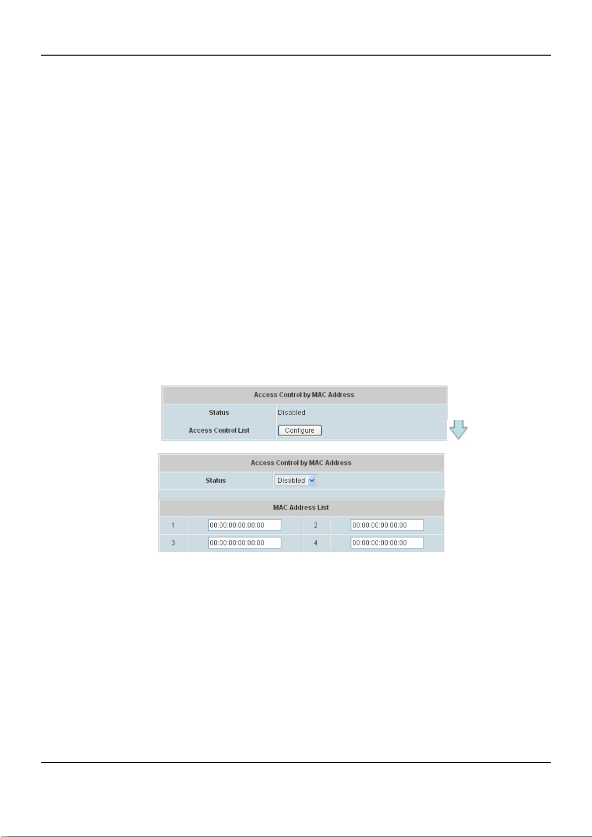
Chapter 4. Web Interface Configuration
○ SSID Configuration Page:
¾ SSID: Service Set Identifier.
¾ Broadcast SSID: Select this option to enable the SSID to broadcast in your network.
When configuring the network, it is suggested to enable this function but disable it when
the configuration is complete. With this enabled, someone could easily obtain the SSID
information with the site survey software and get unauthorized access to a private
network. With this disabled, network security is enhanced and can prevent the SSID from
being seen on networked.
¾ WMM: WMM stands for Wi-Fi Multimedia, by enabling this feature. It will improve the user
experience for audio and video applications over a Wi-Fi network.
¾ Security: Choose one of security types from SSID Configuration, also selecting whether
WEP included or not.
Access Control by MAC Address: MAC address based control for access the network (AP). This function
provides to control the clients’ devices that are allowed to associate with the APs applied with the desired
template setting. Choose Disabled or Enabled in the Status column and enter the desired clients’ MAC
addresses in the MAC Address List. When this function is enabled, please make sure the MAC Address List is
not empty.
75
Page 82
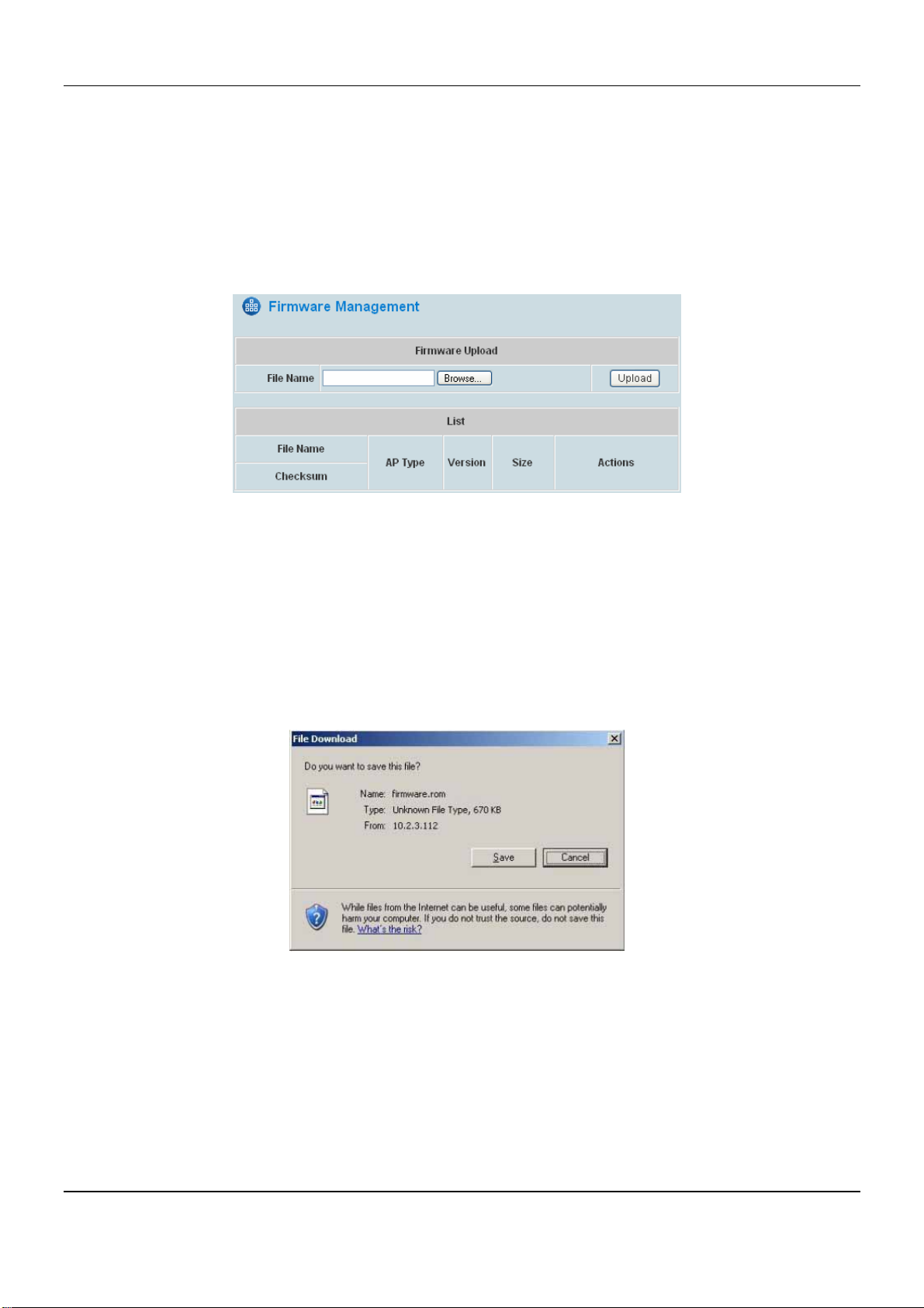
DSA-6100 User Guide
4.3.5 Firmware Management
This is where AP’s firmware can be uploaded. The current firmware can also be downloaded to the local storage if
required.
The system supports the firmware management of APs to upload new firmware, delete the existing firmware, and
download the firmware to managed APs. Note that the AP’s firmware version must be one that has been
integrated.
y File Name: The name of the AP firmware to be uploaded.
y Upload: Click Upload button to upload the file from a local disk to the system.
y List: All uploaded firmware will be listed here.
y Checksum: The automatically detected security identification of the firmware.
y AP Type: The AP type of the firmware.
y Version: The version of the firmware.
y Size: The file size of the firmware.
y Download: Click Download to save the selected firmware to local disk.
y Delete: Can be clicked to delete the current firmware.
76
Page 83
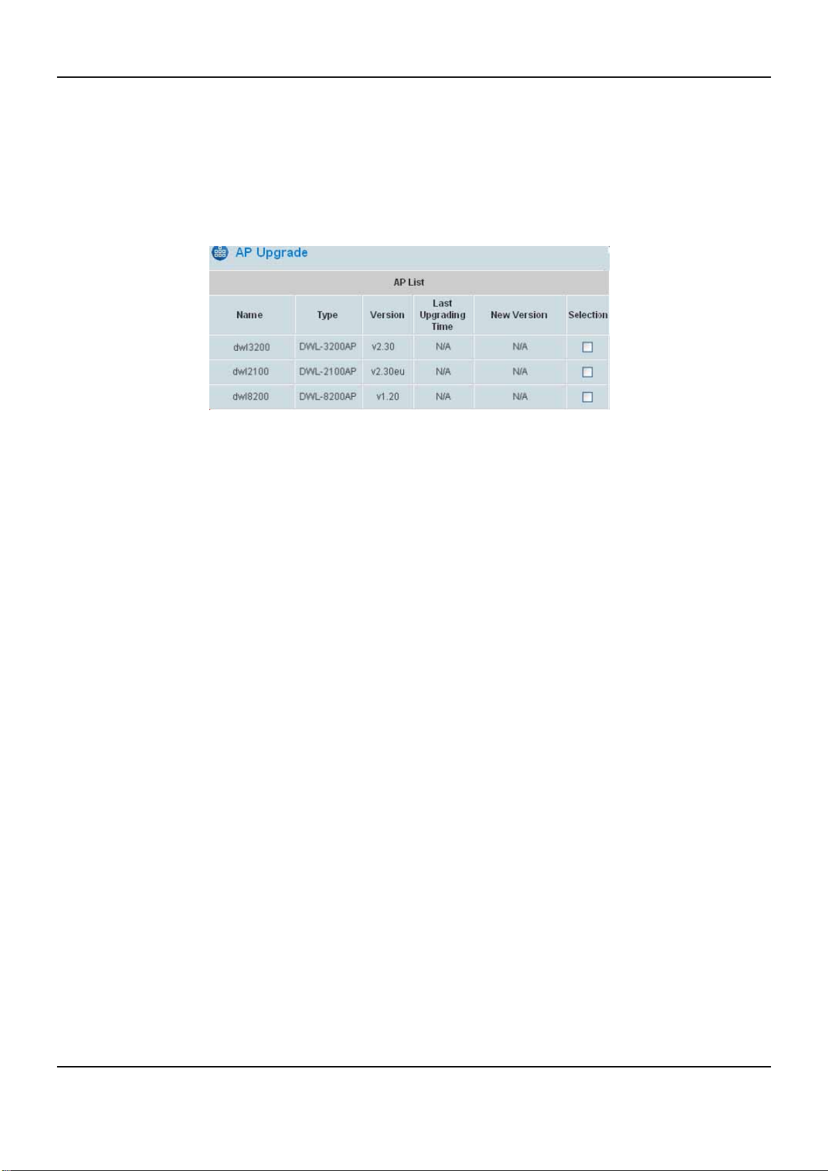
Chapter 4. Web Interface Configuration
4.3.6 AP Upgrade
The administrator can upgrade the firmware of selected APs individually or at the same time by checking the check
box of the APs in Selection column. Note that both the version before upgrade and the next version must be ones
that have been integrated with the system. Check the APs which need to be upgraded and select the upgrade
version of firmware, and click Apply to upgrade firmware.
y Last Upgrading T ime: The time when the AP was last upgraded.
y Ne w Version: The firmware version to be upgrade to the AP.
77
Page 84
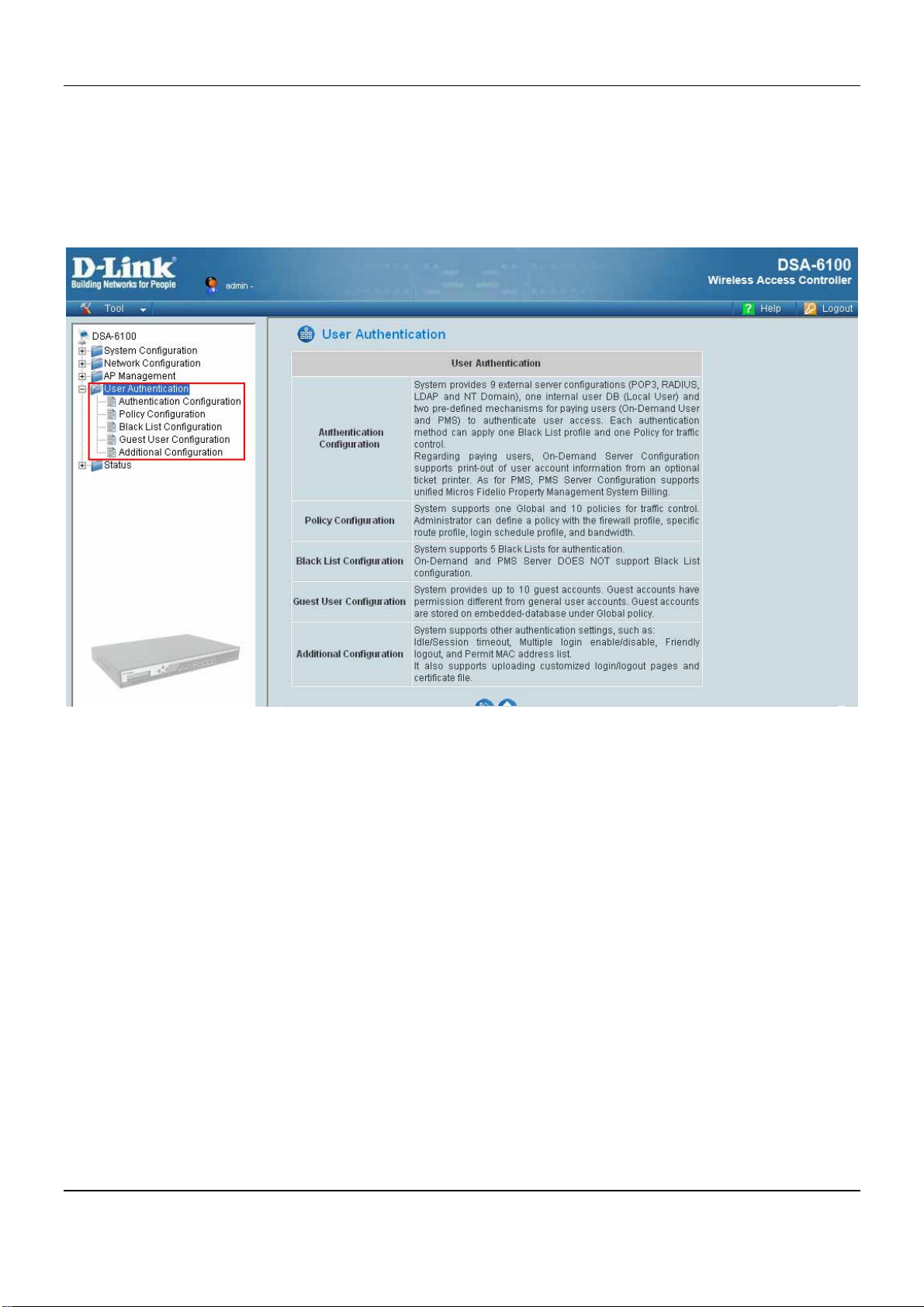
DSA-6100 User Guide
4.4 User Authentication
This section provides information on the following functions: Authentication Configuration, Policy
Configuration, Black List Configuration, Guest User Configuration and Additional Configuration.
78
Page 85
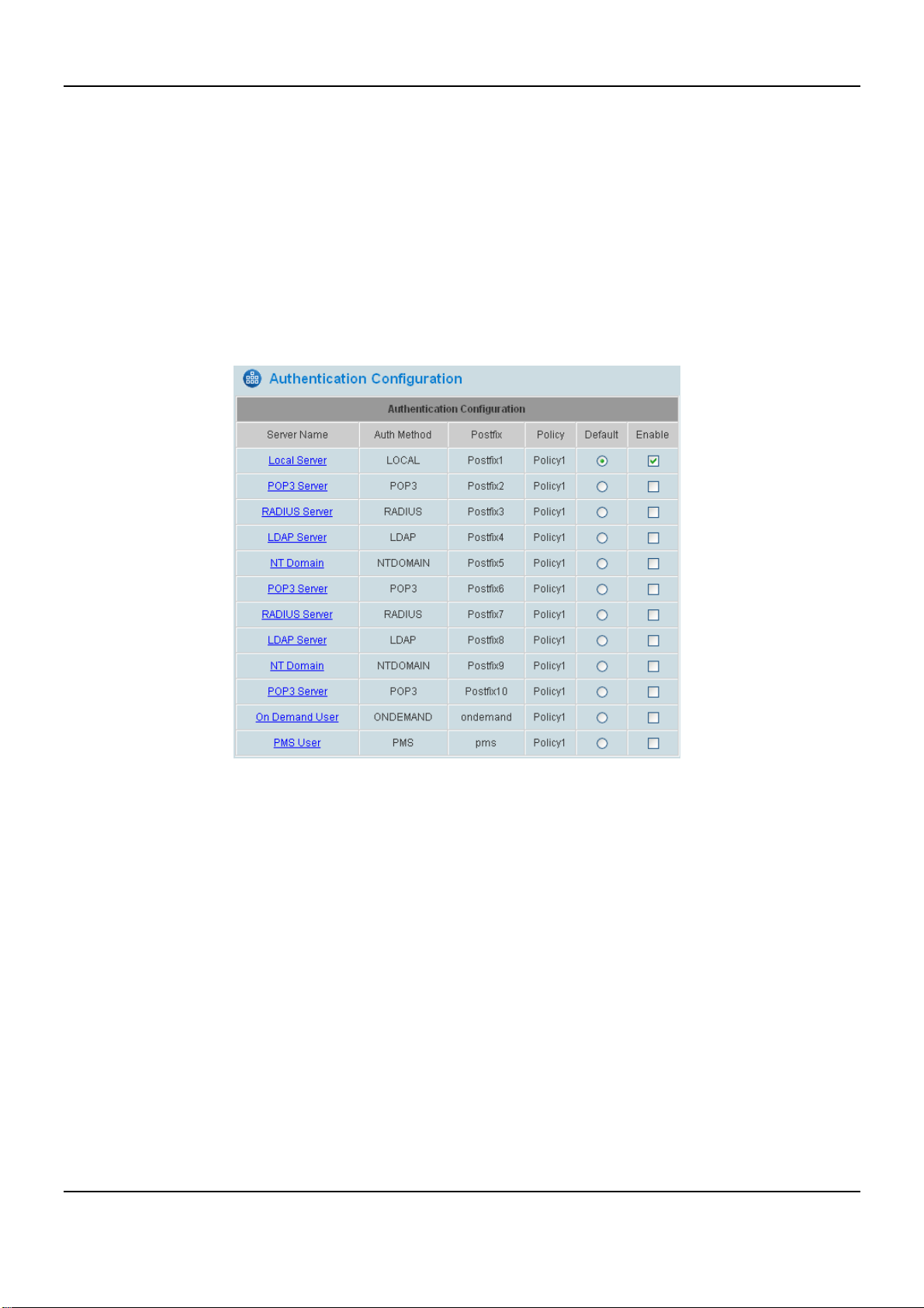
Chapter 4. Web Interface Configuration
4.4.1 Authentication Configuration
The system supports up to 9 external user authentication servers of using one of the RADIUS, LDAP, POP3, and
NT Domain, plus three internal user authentication servers of Local User, On-demand User and PMS User. The
system may authenticate users based on external authentication servers and/or local user database. Each user is
distinguished by the postfix with the username. This function is to configure the settings for different authentication
servers. Using the DSA-6100, on-demand user and PMS user can be administered with different policy. Click on
the server name to set the related configurations for that particular server. After completing and clicking Apply to
save the settings, go back to the previous screen to choose a server to be the default server and enable or disable
any server on the list.
y Server Name: There are several kinds of authentication options supported by DSA-6100: Local Server, POP3
Server, RADIUS Server, LDAP Server, NT Domain, On-demand User and PMS User. Click the hyperlink of the
respective Authentication Option to enter the Authentication Option page.
y Authenticati on Method: The field selects the authentication method used in the server. There are different
authentication methods supported in DSA-6100 Authentication Database: Local, POP3, RADIUS, LDAP, NT
Domain, On Demand and PMS.
y Postfix: Set a postfix that is easy to identify (e.g. local) for the authentication option by using numbers (0~9),
alphabets (a~z or A~Z), dash (-), underline (_) and dot (.) within a maximum of 40 characters. All other
characters are not allowed.
79
Page 86
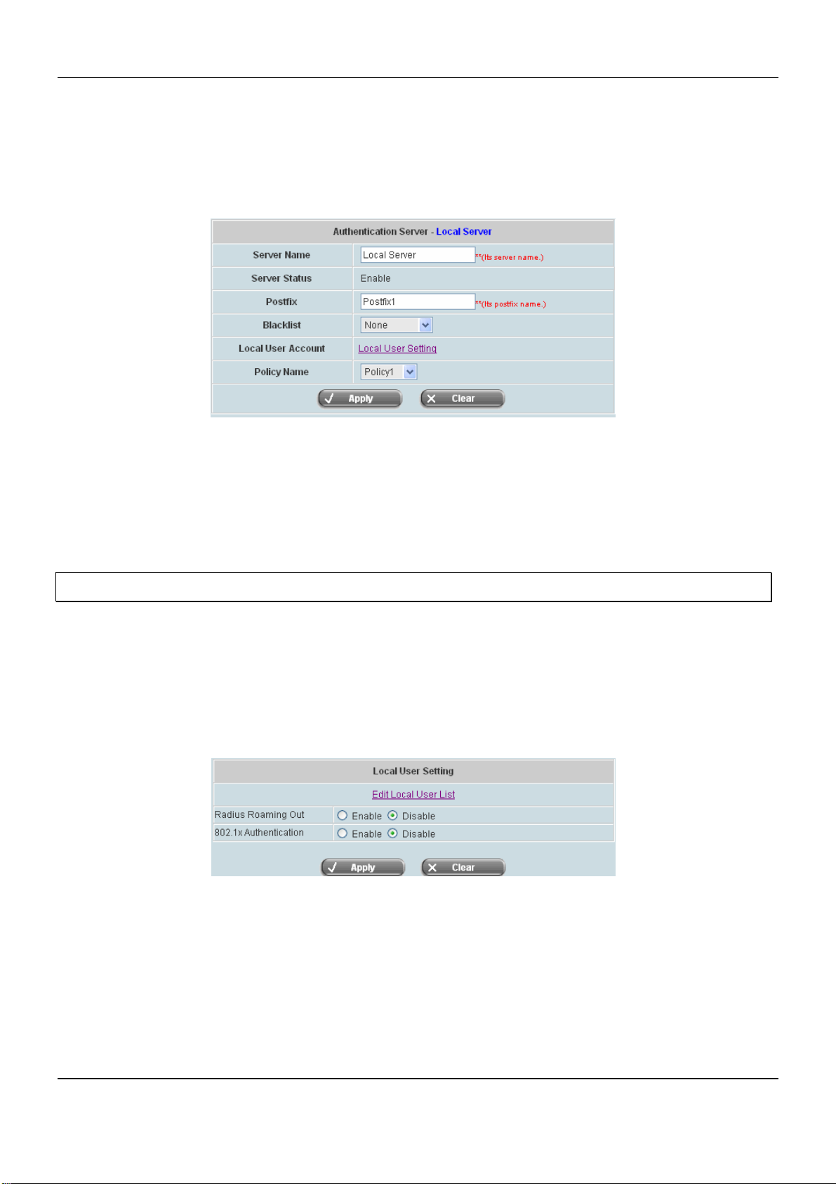
DSA-6100 User Guide
4.4.1.1 Local Server
This server is only for “Local User” and the authentication method can not be changed for this server which
manages user accounts on lists of the local user setting.
Choose “Local Server” in the Server Name field, the hyperlink beside the pull-down menu will become setting of
“Local Server”.
y Server Name: Set a name for the server using numbers (0~9), alphabets (a~z or A~Z), dash (-), underline (_)
and dot (.) with a maximum of 40 characters, all other letters are not allowed.
y Sever Status: The status shows that the server is enabled or disabled.
y Postfix: Set a postfix that is easy to distinguish (e.g. Local) for the server using numbers (0~9), alphabets
(a~z or A~Z), dash (-), underline (_) and dot (.) with a maximum of 40 characters, all other letters are not
allowed.
Warning: The Postfix Name cannot contain these words: MAC and IP.
y Blacklist: There are five sets of the black lists. Select one of them or choose “None”. Please refer to 4.4.3
Black List Configuration.
y Local User Account: Click the Local User Setting hyperlink to set the further configuration.
y Policy Name: There are ten policies to choose from to apply to this particular server.
Clicking in the Local User Setting:
y Edit Local User List: Click this to enter the “User List” screen. View, add, delete and backup user accounts.
y Radius Roaming Out: Enable or disable roaming out. When enabled, this system becomes a RADIUS
server for other external RADIUS clients.
y 802.1x Authentication: Enable or disable 802.1x Authentication. When enabled, this system becomes a
RADIUS server for other external RADIUS clients as long as the RADIUS clients are configured accordingly.
80
Page 87
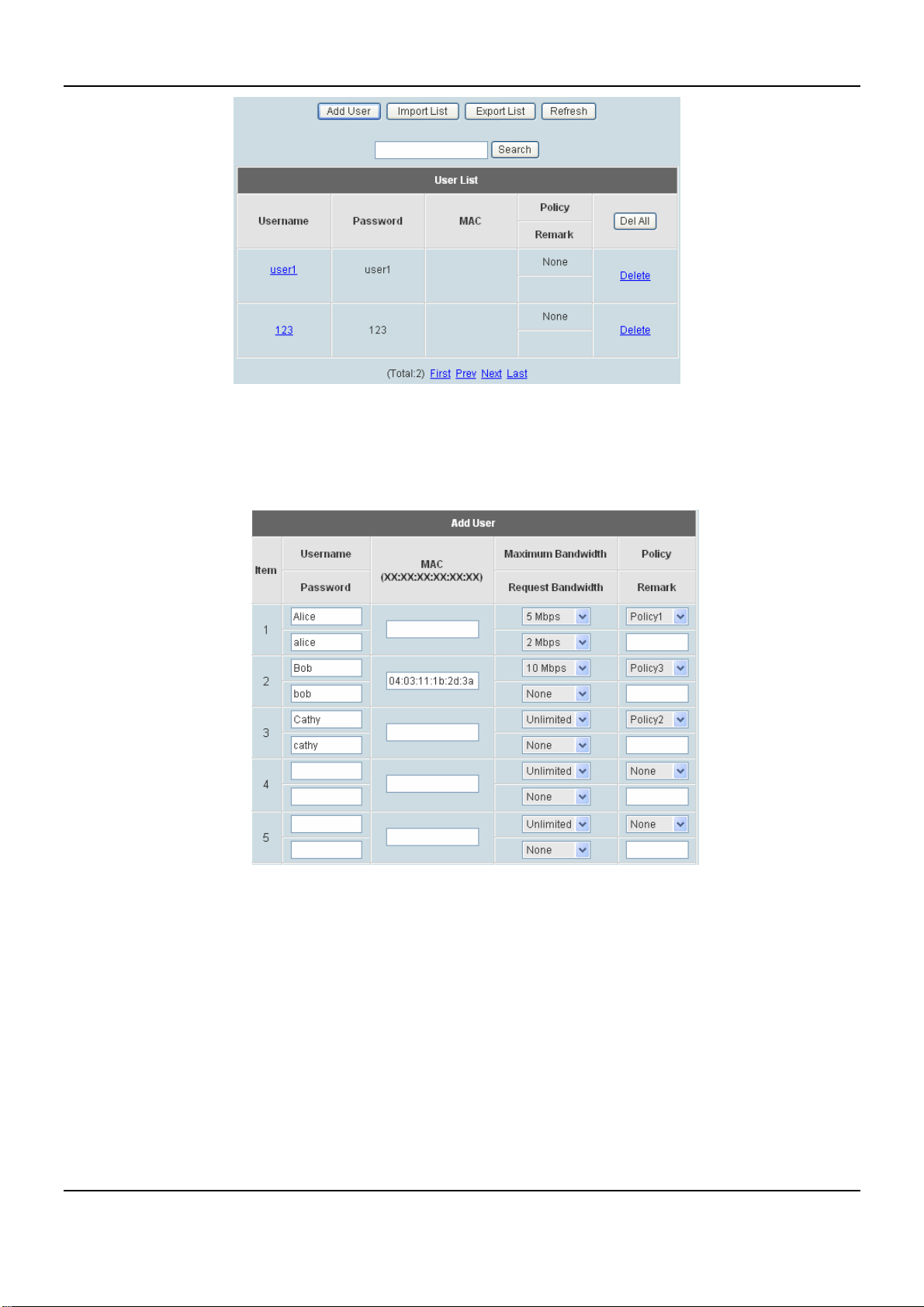
Chapter 4. Web Interface Configuration
Add User: Click this button to enter into the Add User interface. Fill in the necessary information such as
“Username”, “Password”, “MAC” and “Remark”. Select a desired Maximum Bandwidth, Request
Bandwidth and Policy. “Username” and “Password” are required information, the rest are optional,
For the Policy configuration, please check section of Policy Configuration.
81
Page 88
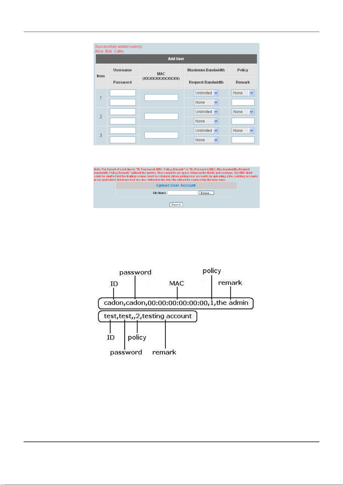
DSA-6100 User Guide
Click Apply to complete adding the user or users
y Import User: Click this to enter the Upload User interface. Click the Browse button to select the text file for
the user account upload. Then click Submit to complete the upload process.
The uploading file should be a text file and the format of each line is "ID, Password, MAC, Policy, Remark"
or “ID, Password, MAC, Max bandwidth, Request bandwidth, Policy, Remark” without the quotes. There
must be no spaces between the fields and commas. The MAC field can be omitted, but the trailing comma
must be retained. When adding user accounts by uploading a file, the existing accounts in the embedded
database will not be replaced by new ones.
82
Page 89
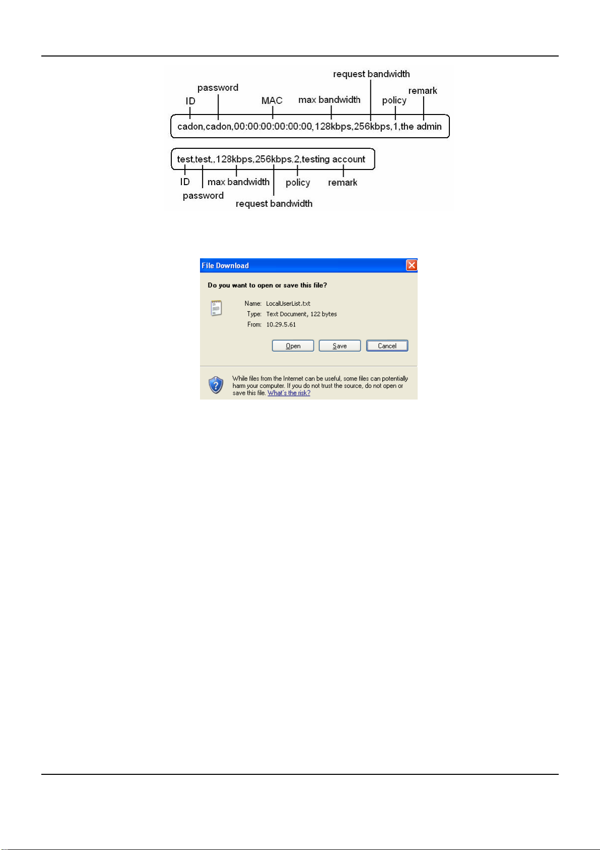
y Export List: Click this to create a .txt file and then save it on disk.
Chapter 4. Web Interface Configuration
83
Page 90
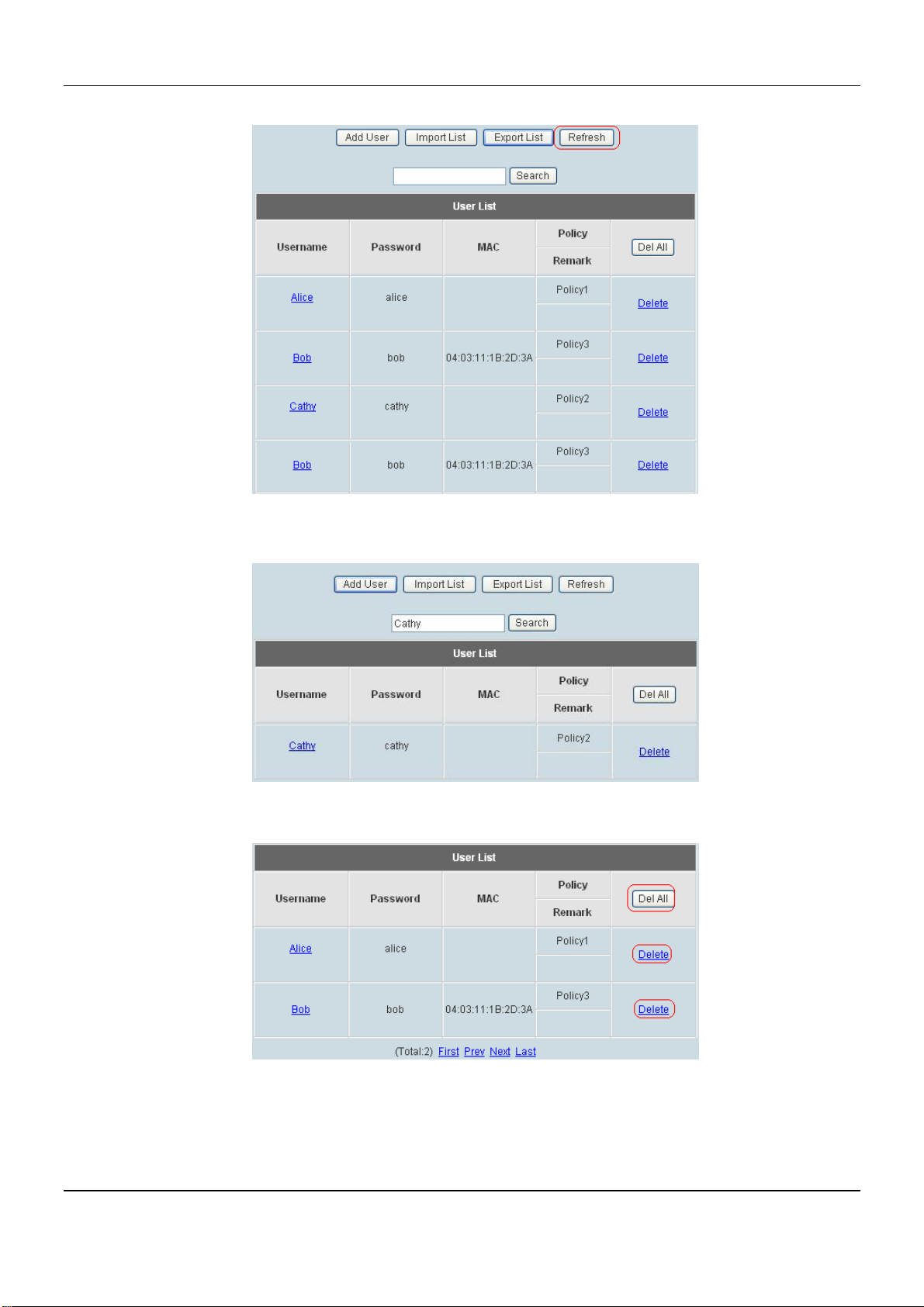
DSA-6100 User Guide
y Refresh: Click this to renew the list. Refresh button.
y Search: Enter a keyword of a username to be searched in the text filed and click this button to perform the
search. All usernames matching the keyword will be listed.
y Del All: click on this button to delete all the users at once and click on Delete to delete the user individually.
y Edit User: If editing the content of individual user account is needed, click the username of the desired user
account to enter the Edit User Interface for that particular user, and then modify or add any desired
information such as “Username”, “Password”, “MAC”, “Maximum Bandwidth”, “Request Bandwidth”,
“Policy” and “Remark” (optional) . Then, click Apply to complete the modification.
84
Page 91
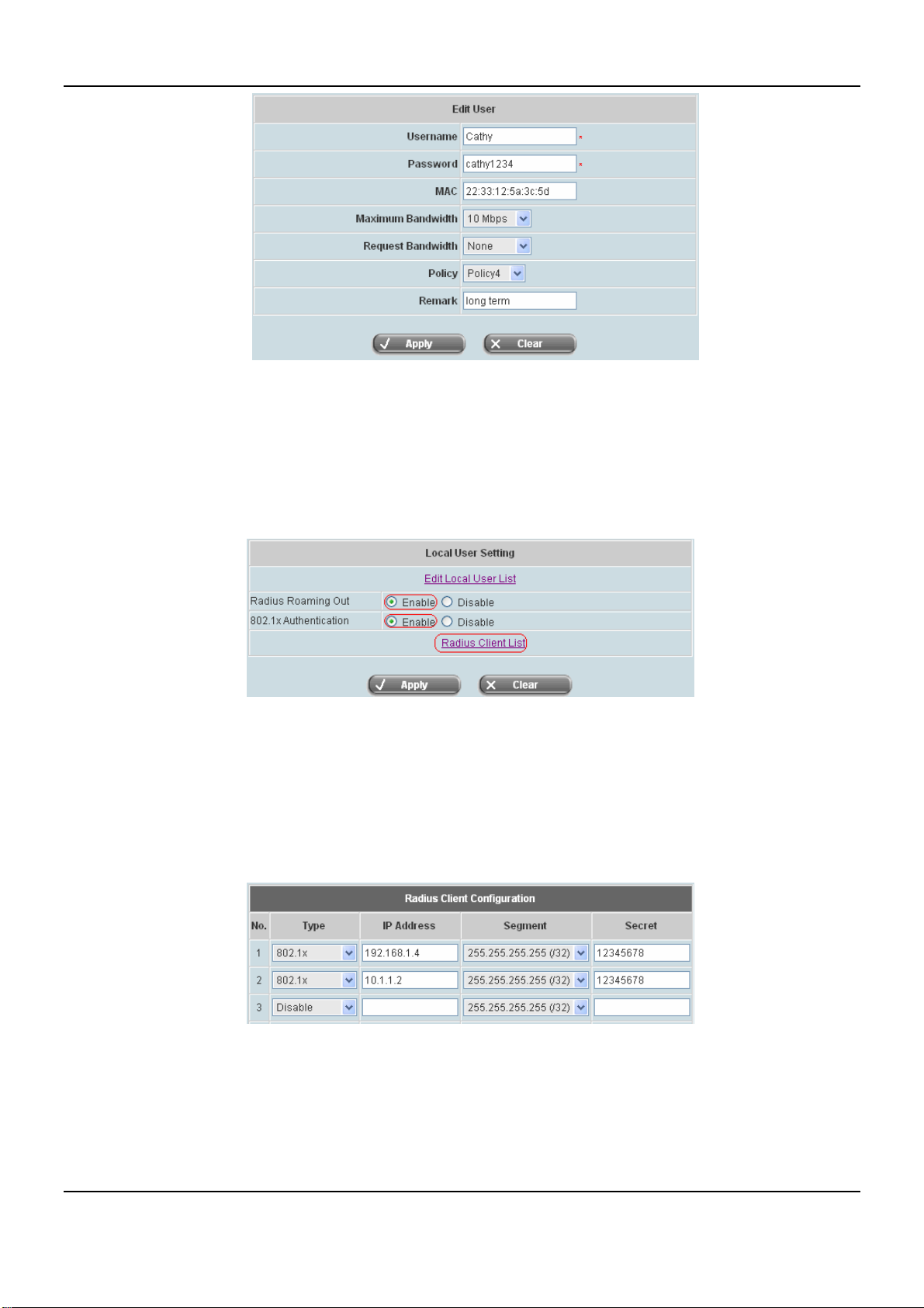
Chapter 4. Web Interface Configuration
y RADIUS Roaming Out / 802.1x Authentication: When RADIUS Roaming Out is enabled, this system
becomes a RADIUS server for other external RADIUS clients. The Local user with RADIUS roaming out
permission need to be configured in the Radius Client List first. The Local user in the list may then log on the
system via the other domain, such as a branch office, as long as the RADIUS clients are configured
accordingly. Selecting either of the options will bring up the hyperlink called RADIUS Client List.
y RADIUS Client List: Configure RADIUS clients and secret key. Local user may log on any of the listed
RADIUS clients as long as the RADIUS clients are configured accordingly.
Click the hyperlink RADIUS Client List to enter the RADIUS Client Configuration interface. Choose the
desired type, Disable, Roaming Out or 802.1x and key in the related data and then click Apply to complete
the settings.
y 802.1x Authentication: 802.1x is a security standard for wired and wireless LANs. It encapsulates EAP
(Extensible Authentication Protocol) processes into Ethernet packets instead of using the protocol's native
PPP (Point-to-Point Protocol) environment, thus reducing some network overhead. It also puts the bulk of the
processing burden upon the client (called a supplicant in 802.1x parlance) and the authentication server
(such as a RADIUS), letting the "authenticator" middleman simply pass the packets back and forth.
85
Page 92
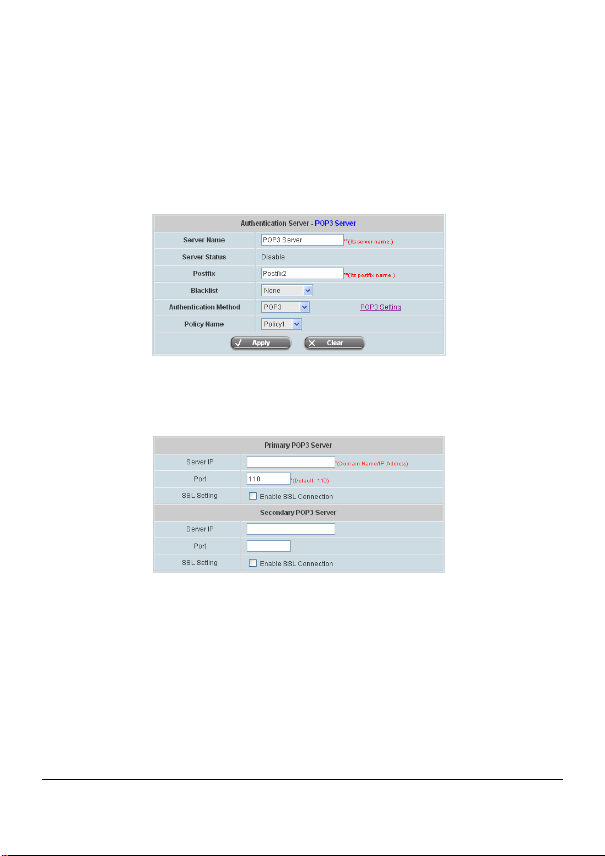
DSA-6100 User Guide
4.4.1.2 POP3 Server
The system may authenticate users using their POP3 email account. You may configure both primary and
secondary POP3 server for fault tolerance. POP3 refers to Post Office Protocol 3, a standard protocol used to
retrieve email stored in a mail server. The system may authenticate users by using POP mail accounts. Two POP3
servers are supported by the system, primary and secondary. When POP3 Server is enabled, at least one POP3
server is needed. Choose “POP3” in the Serv er Name field, the hyperlink beside the pull-down menu will become
“POP3 Setting”.
Click the hyperlink POP3 Setting for further configuration. Enter the related information for the primary server
and/or the secondary server (the secondary server is not required). The blanks with red star are necessary
information. These settings will become effective immediately after clicking the Apply button.
y Server IP: Enter the IP address/domain name given by the ISP.
y Port: Enter the Port given by the ISP. The default value is 110.
y SSL Setting: If this option is enabled, the POP3 protocol will perform the authentication.
86
Page 93
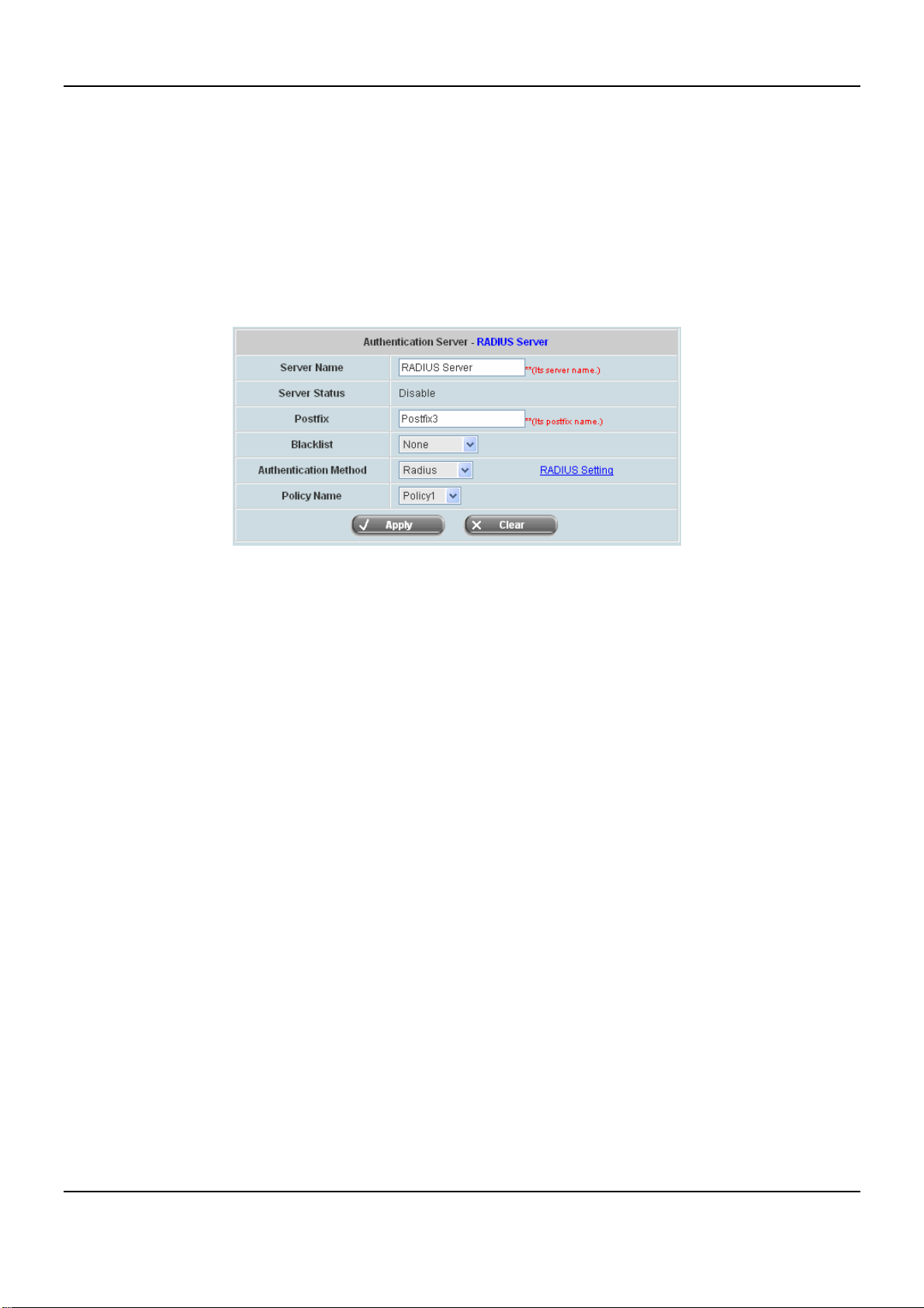
Chapter 4. Web Interface Configuration
4.4.1.3 RADIUS Server
The system supports 802.1x Authentication using external RADIUS server. You may configure both primary and
secondary RADIUS server for fault tolerance. RADIUS refers to Remote Authentication Dial-In User Service, an
authentication and accounting system used by many Internet Service Providers (ISPs). The system may
authenticate users using external RADIUS server including both primary and secondary RADIUS server. Choose
“RADIUS Server” in the Server Name field, the hyperlink beside the pull-down menu will become “RADIUS
Setting”.
Click the hyperlink RADIUS Setting for further configuration. The RADIUS server sets the external authentication
for user accounts. Enter the related information for the primary server and/or the secondary server (the secondary
server is not required). The blanks with red star are necessary information. These settings will become effective
immediately after clicking the Apply button.
87
Page 94
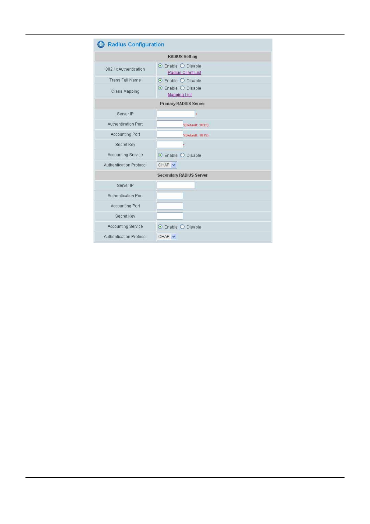
DSA-6100 User Guide
y 802.1X Authentication: When enabled, this system can authenticate RADIUS clients against the external
RADIUS server. Enable this function and the hyperlink of RADIUS Client List will appear. Click the hyperlink to
get into the RADIUS Client Configuration list for further configuration. Please refer to RADIUS Roaming
Out/802.1x Authentication in 4.4.1.1 Local Server.
y RADIUS Client List: The administrator could further set up for the 802.1x capable device that are allowed to
be authenticated against the external RADIUS server via this system. Select type “802.1x Authentication” from
the drop down list, and then enter IP address, Subnet Mask, and shared Secret Key of the authorized devices.
y Trans Full Name: When enabled, both the username and postfix will be transferred to the RADIUS server for
authentication. When disabled, only the username will be transferred to RADIUS server for authentication.
y Class Mapping: Class Attribute can be specified to map to internal Policy.
y Server IP: Enter the IP address/domain name of the RADIUS server.
y Authentication Port: Enter the authentication port of the RADIUS server and the default value is 1812.
y Accounting Port: Enter the accounting port of the RADIUS server and the default value is 1813.
y Secret Key: Enter the key for encryption and decryption.
y Accounting Service: Select this to enable or disable the “Accounting Service” for accounting capabilities.
y Authentication Protocol: Define authentication transmission protocol. Configurations must match remote
RADIUS configurations. PAP (Password Authentication Protocol) transmit password in plain text without
encryption. CHAP (Challenge Handshake Authentication Protocol) is a more secured authentication protocol
using hash encryption.
88
Page 95
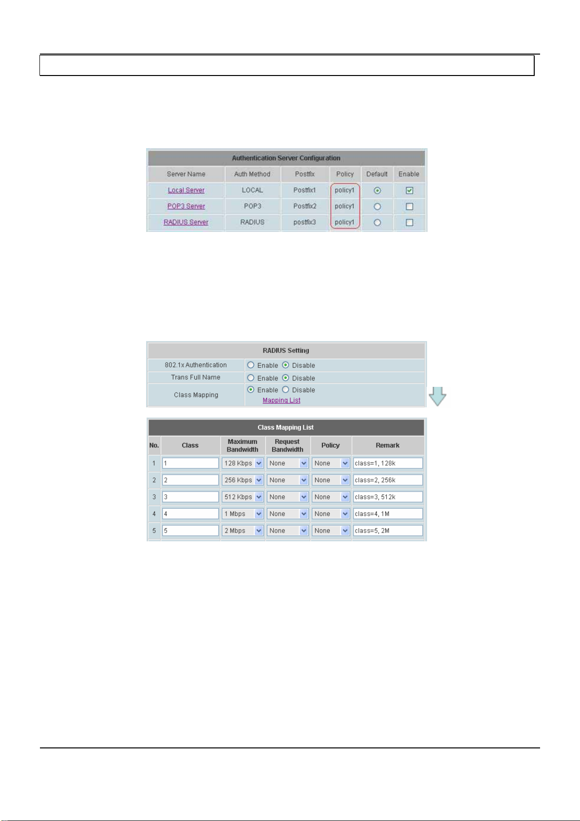
Chapter 4. Web Interface Configuration
Notice: If RADIUS Server does not assign idle-timeout value, DSA-6100 will use the local idle-timeout instead.
y Class Mapping
In DSA6100, each authentication server can be associated with a policy.
The policy at this level is to provide a default policy value. Under a server, a different policy may be further
specified for a specific sub-group or a specific user to override the default policy.
For a RADIUS server, if a class mapping is enabled, a configuration page allows the mapping of RADIUS
class attributes to a policy on DSA-6100. If there is no policy chosen for a RADIUS Class attribute, the total
bandwidth for that RADIUS Class is bounded by the total bandwidth of the default policy of the authentication
server. If there is a specific policy selected for that RADIUS Class attribute, the total bandwidth of that class is
bounded by the total bandwidth of the chosen policy. The maximum bandwidth allowed for the users of a
class is also set in this page of RADIUS Class configuration.
89
Page 96
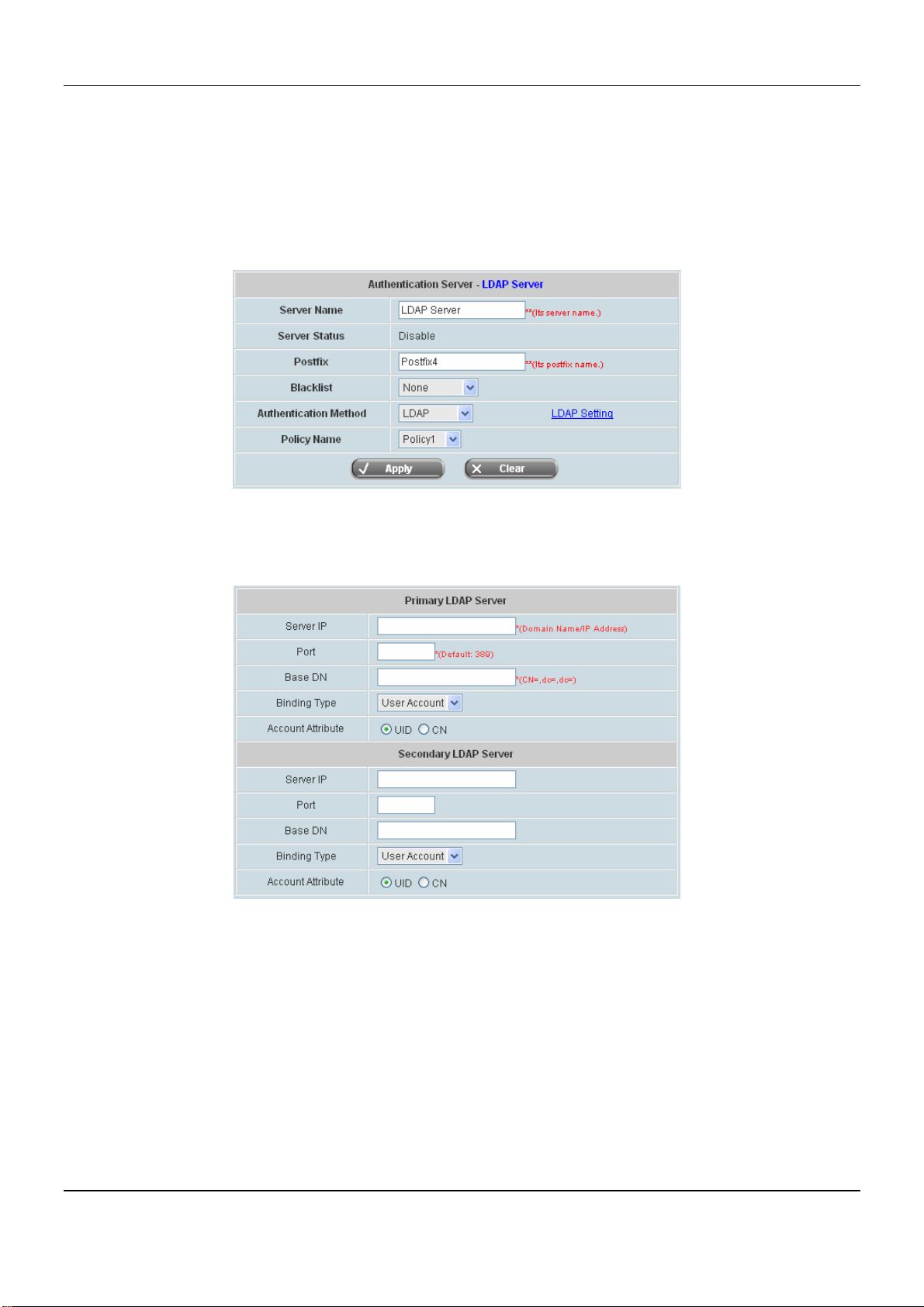
DSA-6100 User Guide
4.4.1.4 LDAP Server
The system may authenticate users using external LDAP server. You may configure both primary and secondary
LDAP server for fault tolerance. LDAP refers to Lightweight Directory Access Protocol, a set of protocols for
accessing information directories. The system may authenticate users using external LDAP server including both
primary and secondary. Choose “LDAP” in the Server Name field, the hyperlink beside the pull-down menu will
become “LDAP Setting”.
Click the hyperlink LDAP Setting for further configuration. Enter the related information for the primary server
and/or the secondary server (the secondary server is not required). The blanks with red asterisk are necessary
information. These settings will become effective immediately after clicking the Apply button.
y Server IP: Enter the IP address/domain name of the LDAP server.
y Port: Enter the Port of the LDAP server, and the default value is 389.
y Base DN: Enter the distinguished name of the LDAP server.
y Binding Type: There are four binding types, User Account, Anonymous, Specific DN and Windows AD to
select.
¾ User Account: Use the user account’s login username and password of the system, and then select one
Account Attribute (UID, CN) to access the LDAP server.
y Account Attribute: Attribute of LDAP accounts.
90
Page 97
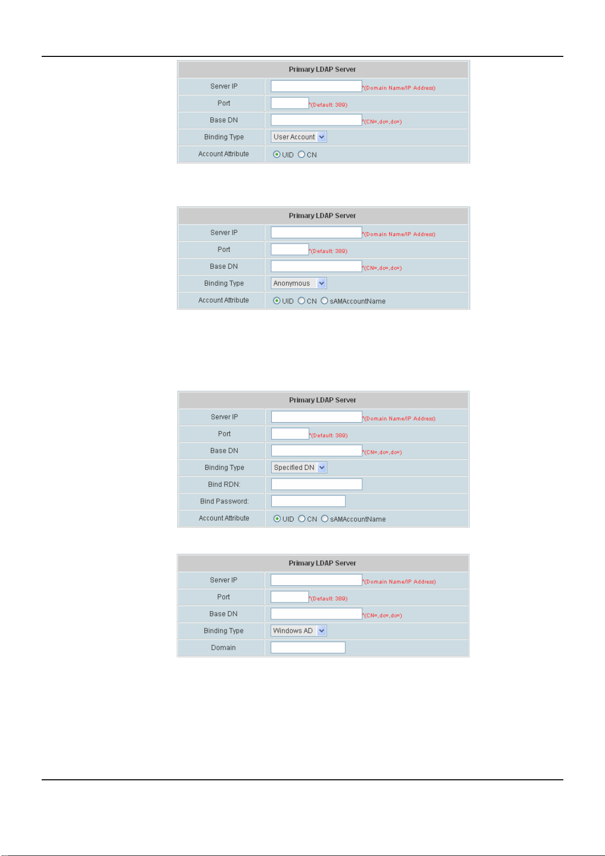
Chapter 4. Web Interface Configuration
Anonymous: Access the LDAP servers without requiring authentication but only select one Account
Attribute (UID, CN or Account Name).
Specified DN: Entering the specific DN username and password in the “Bind RDN” and “Bind
Password” fields, and then select one Account Attribute (UID, CN or Account Name) to access the
LDAP server.
Windo w AD: Enter the domain name of Windows AD to access the LDAP server.
91
Page 98
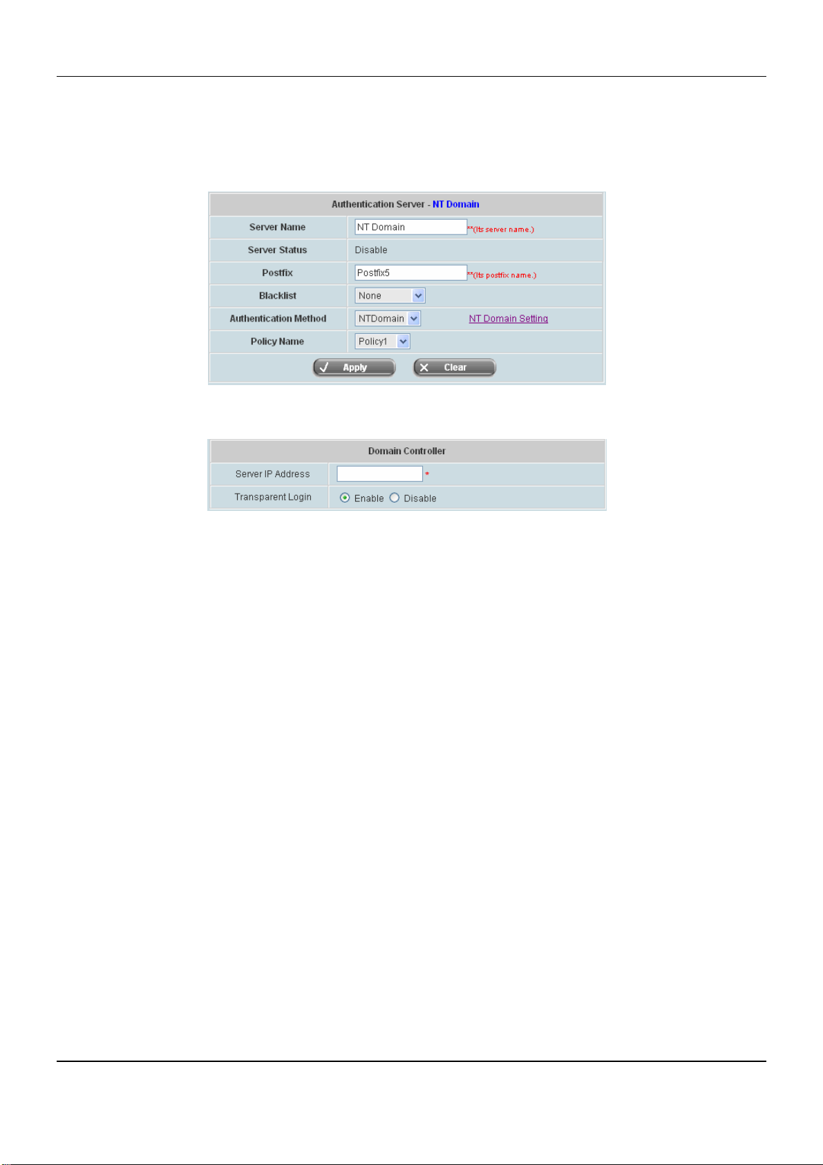
DSA-6100 User Guide
4.4.1.5 NT Domain Server
This system may authenticate users using external MS Domain Server. NT Domain Server refers to external MS
Domain Server. Choose “NTDomain” in the Server Name field, the hyperlink beside the pull-down menu will
become “NT Domain Setting”.
Click the hyperlink NT Domain Setting for further configuration. Enter the server IP address and enable/disable
the transparent login function. These settings will become effective immediately after clicking the Apply button.
y Server IP Address: Domain Server IP address. Enter the server IP address of the domain controller.
y Transparent Login: Enable this option for transparent user login to MS Domain.
92
Page 99
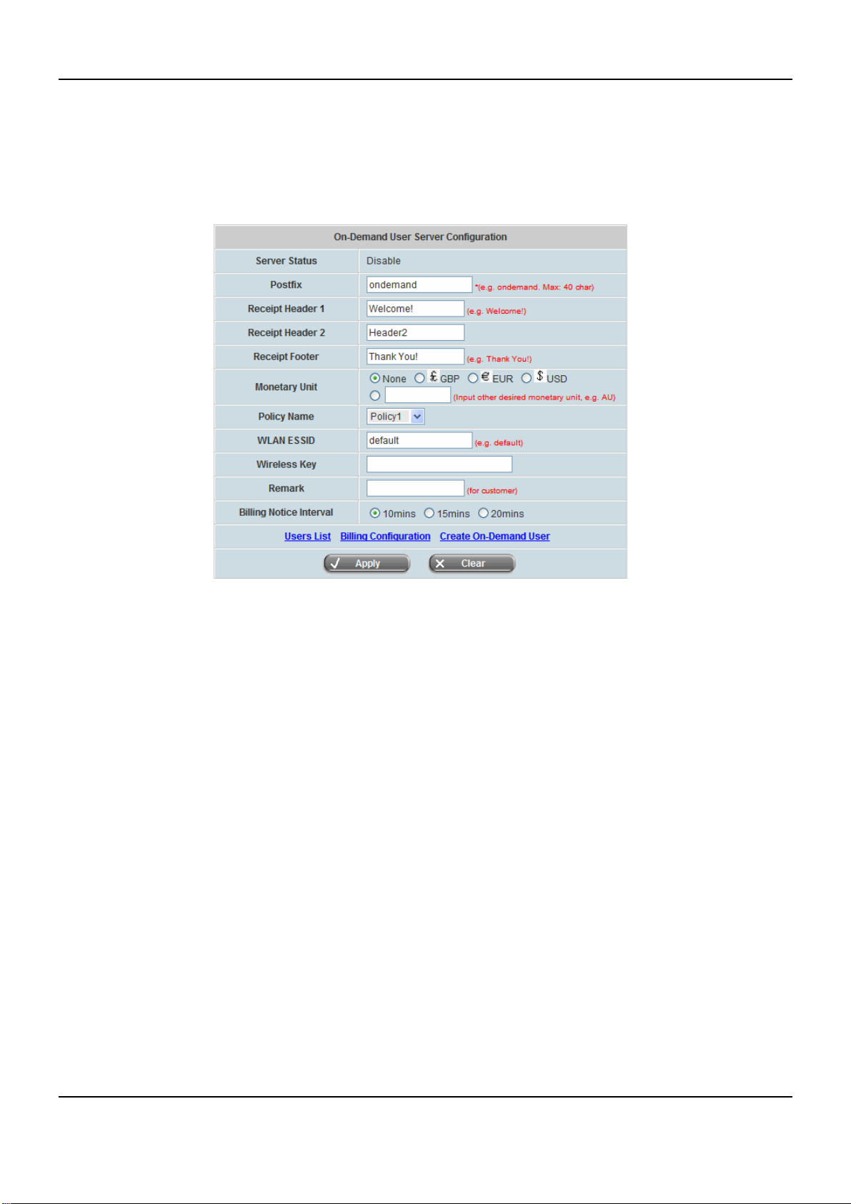
Chapter 4. Web Interface Configuration
4.4.1.6 On Demand User
This is needed in a retail environment. When customers need to use wireless Internet in a store, they have to get a
printed receipt with username and password from the store to log in the system for wireless access. Choose “On
Demand User” in the Server Name field, the hyperlink beside the pull-down menu will become “On-Demand
User Server Configuration”.
¾ Server Status: The status shows that the server is enabled or disabled.
¾ Postfix: Set a postfix that is easy to distinguish (e.g. Local) for the server using numbers (0 ~ 9),
alphabets (a ~ z or A ~ Z), dash (-), underline (_) and dot (.) with a maximum of 40 characters. All other
letters are not allowed.
¾ Receipt Header 1/2: There are two fields, Receipt Header 1 and Receipt Header 2, for the receipt’s
header. Enter receipt header message or use the default.
¾ Receipt Footer: Enter receipt footer message here or use the default.
¾ Monetary Unit: Select the desired monetary unit for a region or input the needed monetary unit if not
listed.
¾ Policy Name: Select a policy for the on-demand user.
¾ WLAN ESSID: Enter the ESSID of the AP.
¾ Wireless Key: Enter the Wireless key of the AP.
¾ Remark: Enter any additional information that will appear at the bottom of the receipt.
¾ Billing Notice Interval: While the on-demand user is still logged in, the system will update the billing
notice of the login successful page by the time interval defined here.
93
Page 100
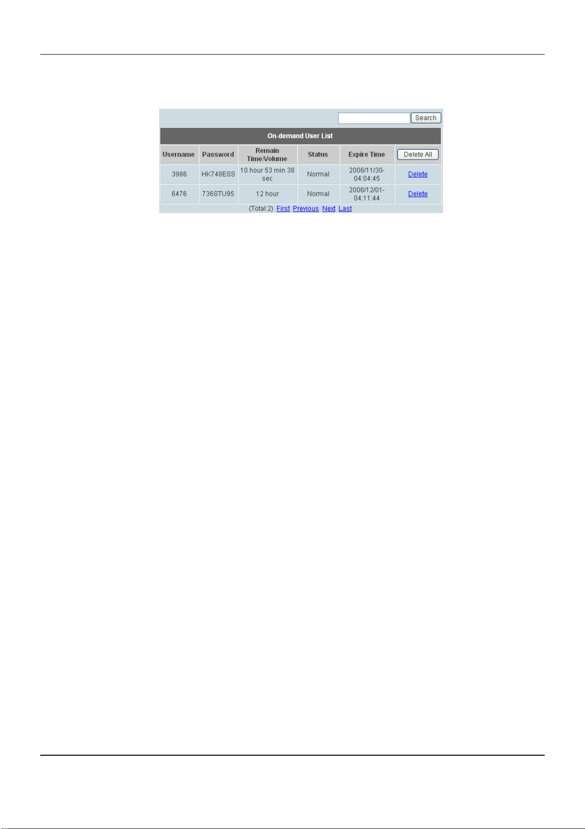
DSA-6100 User Guide
A. User List: The page shows all valid on-demand accounts and their status. Click to enter the On-demand User
List screen. In the On-demand User List, detailed information will be documented here. By default, the
On-demand user database is empty.
y Search: Enter a keyword of a username to be searched in the text filed and click this button to perform the
search. All usernames matching the keyword will be listed.
y Username: The login name of the on-demand user.
y Password: The login password of the on-demand user.
y Remain Time/Volume: The total Time/Volume that the user can use currently.
y Status: The status of the account.
¾ Normal indicates that the account is not in-use and not overdue.
¾ Online indicates that the account is in-use and not overdue.
¾ Expire indicates that the account is overdue and cannot be used.
y Expire Time: The expiration time of the account.
y Del All: This will delete all the users at once.
y Delete: This will delete the users individually.
94
 Loading...