

Page 1

DRO-250i Router
Users Guide
Rev 1.0(MAY 2006)
Page 2

Introduction to DRO-250i
Table of contents
INTRODUCTION TO DRO-250i ......................................................4
1.1 Overview....................................................................................4
1.2 Product Features........................................................................5
1.2.1 Hardware Features...............................................................5
1.2.2 Software Features................................................................7
INSTALLING DRO-250i ...............................................................12
2.1 About the router .......................................................................12
2.1.1 Front Panel ...................................................................13
2.1.2 Rear Panel.....................................................................15
2.2 Unpacking the DRO-250i.........................................................15
2.1.3 Mounting the DRO-250i.................................................16
2.3 Connecting the DRO-250i to your network ..............................17
2.4 Configuration via Web Browser................................................18
CONFIGURATION THROUGH WEB............................................20
3.2 Interfaces..........................................................................20
3.2.1 Interfaces -LAN..............................................................20
3.2.2 Interfaces - WAN 1.........................................................22
3.2.3 Interfaces – WAN2.........................................................23
3.2.3.1 Mode Settings...........................................................23
3.2.3.2 WAN2-Dial Up..........................................................24
3.2.3.2.1Dial Up-Connection Settings.................................24
3.2.3.2.2Dial Up-Dial out.....................................................27
3.2.3.2.3Dial Up-Dial In.......................................................30
3.2.3.3 WAN2-Dial................................................................33
3.2.4 Interfaces –WAN3..........................................................35
3.2.5 Interfaces – WAN 4........................................................39
3.2.5.1 WAN 4 - Dial Out......................................................39
3.2.5.2 WAN 4 - Dial In Configuration ..................................41
3.2.5.3 WAN 4 - Dial In User Account..................................42
3.2.5.4 WAN 4 - Modem Configuration.................................43
DRO-250i User Manual
1
Page 3

Introduction to DRO-250i
3.2.5.5 WAN 4 - Serial Port Settings....................................45
3.2.6 Interfaces -BACKUP CONFIG.......................................46
3.2.7 Interfaces -DMZ/WAN3..................................................48
3.3 Routing .............................................................................49
3.4 Advanced..........................................................................55
3.4.1 Advanced - DHCP..........................................................55
3.4.1.1 DHCP - DHCP Servers.............................................55
3.4.1.2 DHCP -DHCP Reservation.......................................58
3.4.2 Advanced -DNS Proxy...................................................59
3.4.3 Advanced -NAT..............................................................60
3.4.3.1 NAT - Interface Configuration...................................60
3.4.3.2 NAT - NAT Configuration..........................................61
3.4.4 NAT - Advanced NAT ....................................................63
3.4.5 Advanced - Virtual Server..............................................64
3.4.6 Advanced –FIREWALL..................................................66
3.4.6.1 Firewall-Interface Configuration...............................66
3.4.6.2 Firewall- POLICY......................................................68
3.4.6.3 Firewall – IDS Configuration.....................................71
3.4.7 Advanced -VPN .............................................................74
3.4.7.1 VPN – VPN-IPSEC...................................................74
3.4.7.2 VPN - Tunnel............................................................76
3.4.7.3 VPN -Tunnel Table...................................................80
3.4.8 Advanced - Load Balancing...........................................81
3.4.8.1 Load Balancing-Policy Based...................................81
3.4.8.2 Load Balancing-Weight Based.................................83
3.4.9 Advanced – Li n k Dete ct io n............................................84
3.4.10 Advanced – SNMP.........................................................86
3.4.10.1 SNMP-SNMP Configuration .....................................86
3.4.10.2 SNMP-TRAP Configuration......................................89
3.5 Multicast............................................................................91
3.5.1 Multicast – Multicast.......................................................91
3.5.2
Multicast - Multicast Routing.........................................92
3.6 QoS...................................................................................94
3.6.1 QoS –Q-Discipline .........................................................94
3.6.2 QOS - Filter Configuration .............................................99
3.7 Tool.................................................................................101
3.7.1 Tools - Admin...............................................................101
DRO-250i User Manual
2
Page 4

Introduction to DRO-250i
3.7.2 Tools - System.............................................................102
3.7.3 Tools - Upload..............................................................103
3.7.4 Tools - Ping Test..........................................................104
3.7.5 Tools - Time.................................................................105
3.7.6 Tools - System Log......................................................107
3.7.7 Tools - Remote Access................................................108
3.8 Status..............................................................................110
3.8.1 Status - Device Info......................................................110
3.8.2 Status - Route Table....................................................112
3.8.3 Status – Multicast.........................................................113
3.8.4 Status - NAT Info .........................................................115
3.8.5 Status - IPsec Status ...................................................116
3.8.6 Status - Log..................................................................118
3.8.6.1 Status - Log - Intrusion Log....................................118
3.8.6.2 Status –Log- Blocking Log......................................120
3.8.6.3 Status- Log- Session Log.......................................121
3.8.6.4 Status- Log - IPSec Log .........................................122
3.8.6.5 Status - Log - Black list...........................................123
3.8.7 Status – Traffic.............................................................124
3.8.8 Status – ISDN ..............................................................125
3.8.9 Status - WAN4 Dial......................................................126
3.9 HELP ..............................................................................128
APPENDIX...................................................................................129
Password Recovery:....................................................................129
Warranty Policy
…………………………………………………………………………130
DRO-250i User Manual
3
Page 5

Introduction to DRO-250i
CHAPTER 1
INTRODUCTION TO DRO-250i
1.1 Overview
Nowadays LAN, WAN and Internet connectivity are becoming the
common currency for business. Intranets and Internet are carrying a
growing percentage of business transactions for data & voice
communication. For SOHO businesses and enterprise branch offices
interconnecting the company, Intranet and Internet is becoming a
competitive necessity. Such enterprise businesses also require solutions
that provide reliable, secure and high-performance access to their private
WANs and the Internet with flexibility to upgrade to new services easily
in the near future. Service providers are interested in meeting this demand
for new network services to capitalize on opportunities with the growing
SOHO & enterprise market.
D-Link’s DRO-250i Router is designed for small and medium enterprises.
It has 1 LAN port and 4 WAN ports.
The supported WAN Ports are:
- 2 Mbps V.35 interface.
- 64/128kbps ISDN Leased/Dialup interface.
- Ethernet/PPPoE WAN (re-configurable as DMZ) interface.
- Aux port
It supports Manual and Automatic Back-Up feature. When a primary
interface goes down all the traffic can be redirected through the configured
backup interface.
DRO-250i Router is targeted for low cost market in SOHO segment. This
router uses XScale architecture (ARM core with NPEs) from INTEL
(IXP425). The hardware is designed with 5 Interfaces (V.35, LAN, ISDN,
& WAN3/DMZ, Aux Port). Any interface can be made as primary WAN
interface. Similarly any interface can be made as backup WAN interface.
For example V.35 is used as Primary interface for WAN connectivity
DRO-250i User Manual
4
Page 6

Introduction to DRO-250i
which ideally gives bandwidth up to 2Mbps. ISDN WAN interface can be
a backup interface which gives 128kbps bandwidth
1.2 Product Features
1.2.1
Hardware Features
LAN Port
The Product is equipped with an auto-negotiated 10/100 (Ethernet) RJ-45
interface for connecting the router to the LAN.
Multiple WAN Ports
The Product has 4 WAN ports.
V.35 WAN Interface
V.35 can be connected to 2 Mbps Leased Modem.
ISDN WAN Interface
ISDN S/T Port is connected to either a dial up line or a dedicated leased
line. It also supports bandwidth on Demand (BOD). Following protocols
are only supported within ISDN sub system:
Layer 2 protocol: HDLC
Layer 3 protocol: Trans
Dial on Demand
The dial on demand feature allows the product to automatically place
a call to a remote node via ISDN WAN port whenever there is traffic
coming from any workstation on the LAN to that remote site.
DRO-250i User Manual
5
Page 7

Introduction to DRO-250i
Auto Hang-up
The product can be configured for Auto Hang-up with idle times
which can hang-up the ISDN WAN connection when the line stays
idle for predetermined time duration. To disable this feature set idletimeout to 0 in ISDN Configuration page.
Bandwidth on Demand
This product supports the Bandwidth on Demand feature.
PPP/MLPPP
ISDN WAN port uses Sync-PPP for PPP negotiation with the ISP.
64 Kbps line uses only Sync-PPP. MLPPP is used in conjunction
with 128 Kbps line.
Ethernet WAN Interface
This Ethernet interface can be used to connect the WAN interface by using
any broadband modem. It can be connected in the following 3 modes.
1. Dynamic connection: Using the DHCP client, it will get connect
to the broadband.
2. PPPoE: Point to Point link over Ethernet. It is the widely used
mode to connect broadband network.
3. Static: Statically define the Interface address and connect to the
WAN world.
Auxiliary WAN Interface
This is one of the legacy interfaces to connect the WAN. This interface
can be used as backup interface to any primary interfaces (Ethernet WAN,
V.35).
DRO-250i User Manual
6
Page 8

Introduction to DRO-250i
Bandwidth available with WAN
V.35 2Mbps
ISDN 64Kbps, 128Kbps & Bandwidth on Demand
Ethernet Wan 100Mbps
Aux Port 56Kbps
1.2.2 Software Features
Routing
DRO-250i supports both the dynamic and static routing. As part of
dynamic routing it supports RIP and OSPF routing protocols.
RIP
The Routing Information Protocol, or RIP, as it is more commonly
called, is one of the most enduring of all routing protocols.DRO-250i
supports both the versions of V1 and V2.
OSPF
Short for Open Shortest Path First, an interior gateway routing
protocol developed for IP networks based on the shortest path first or
link-state algorithm. DRO-250 supports both the version of OSPF.
Static Routing
Static routes are special routes that the network administrator
manually enters into the router configuration. You could build an
entire network based on static routes.
DRO-250i User Manual
7
Page 9

Introduction to DRO-250i
Load balancing
User can connect to multiple WAN networks and the load can be
distributed to between these multiple WAN interfaces to get good
bandwidth. If any interface goes down the traffic will be diverted back to
the connected interfaces.
Firewall
The DRO-250i also includes a firewall which has the following features:
• Access Policies
• Network Address Translation (NAT/NAPT) with Popular ALG
Support.
• Inbound and Outbound policies for all the interfaces.
• Intrusion detection system (IDS)
• Denial of Service (DoS) and Distributed Denial of Service (DDoS)
• Filter like IP address, port, domain name, Mac address, URL etc.,
• Virtual servers
• Port forwarding
VPN
Using the DRO-250i integrated VPN, you can provide a secure connection
between widely separated office networks or securely link telecommuters
or travellers to the office network. An encrypted traffic tunnel is created
between DRO-250i protected networks or between a DRO-250i and third
party VPN products that support IPSec.
NAT
When a TCP or UDP packet is received by the Router the IP address in
this packet will be translated between the WAN and LAN side of the
Router if this option is enabled. DRO-250i supports all the combinations
of NAT models like Many to Many, Many to One, One to Many, One to
One
DRO-250i User Manual
8
Page 10

Introduction to DRO-250i
Quality of Service
Router provides QoS mechanisms pertaining to differentiated services. In
an IP network QoS defines the ability to compensate for traffic
characteristics without compromising average throughput.
QoS enables you to provide better service to certain flows. This is done by
either raising the priority of a flow or limiting the priority of another flow
SNMP
DRO-250i supports SNMPV1, V2 &V3 to allow user to monitor the
device through any SNMP manager. This feature allows network
administrators to manage network performance, find and solve network
problems, and plan for network growth.
Multicasting
Internet Protocol (IP) multicast is a bandwidth-conserving technology that
reduces traffic by simultaneously delivering a single stream of information
to thousands of corporate recipients and homes. Applications that take
advantage of multicast include videoconferencing, corporate
communications, distance learning, and distribution of software, stock
quotes, and news. DRO-250i routers are enabled with Protocol
Independent Multicast (PIM) and other supporting multicast protocols like
IGMP
Tools
DRO-250i supports various tools to manage and monitor the device.
DRO-250i User Manual
9
Page 11

Introduction to DRO-250i
Syslog
The Router can send the Syslog messages to the configured server to
aid in network administration.
NTP
Router allows the user to configure the system date and time. User
can select to use either manual or SNTP settings to set the time.
Configuration upload/download
This tool allows the user to save the configurations onto the product
as well as it can be downloaded to the local hard disk. The same
configuration can be uploaded to the device.
Web Based Configuration and Management
The product provides SSL based secure, user friendly Web Pages to
configure and manage the device and the network.
Internet Access
The product supports the TCP/IP protocol which is the protocol language
for the Internet. DRO-250i Router allows everyone connected to the LAN
to access the Internet.
NAT feature is required at LAN side to access ISP through any WAN
connection.
DRO-250i User Manual
10
Page 12

Introduction to DRO-250i
Chapter 2 and 3 will give the detail info on how to install/configure the
DRO-250i router.
DRO-250i User Manual
11
Page 13
Installing DRO-250i
CHAPTER 2
INSTALLING DRO-250i
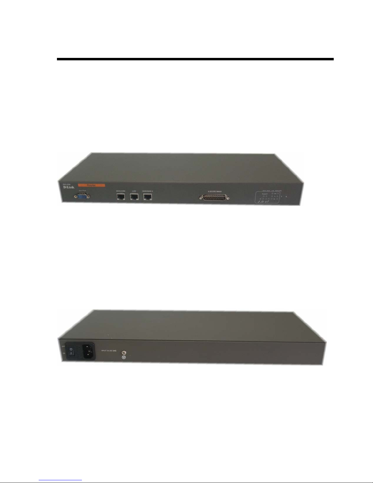
2.1 About the router
This section will introduce hardware of the router.
Front View
Rear View
DRO-250i User Manual
12
Page 14
Introduction to DRO-250i
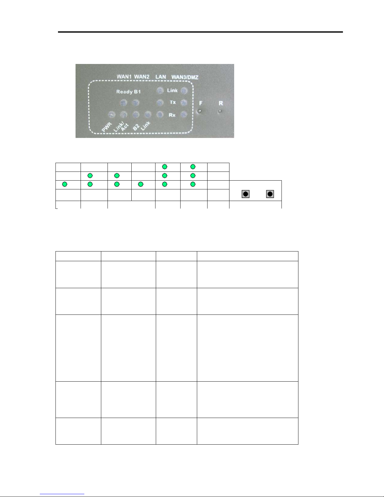
3.1.1 Front Panel
1 3 5 6 9 12
PWR WAN1 WAN2 LAN WAN3 SWT
Number
1
2
3
4
2
4
Module Status Description/Designation
Power On ON
WAN1 (V.35) Ready ON: Interface is up
WAN1 (V.35) Link
WAN2
(ISDN)
5
WAN2
(ISDN)
7
10
8 11
/ACT
Link ON : Physical link is up
B1 ON: B1 Connected
F R
13
14
OFF
OFF: Interface is down
ON: There is activity on
this interface
OFF: There is no activity
on this interface
Blinking: There is activity
through v.35
interface
OFF : Physical link is
down
OFF: B1 Disconnected
DRO-250i User Manual
13
Page 15

Installing DRO-250i
6
7
8
9
10
11
12
13
14
WAN2
(ISDN)
B2 ON: B2 Connected.
OFF: B2 Disconnected
LAN Link ON : Physical link is up
OFF: Physical link is
down
LAN Tx ON : Transmission Activity
on
OFF: Transmission Activity
off
LAN Rx ON: Receive Activity on
OFF: Receive Activity off
WAN3/DMZ Link ON : Physical link is up
OFF : Physical link is
down
WAN3/DMZ Tx ON : Transmission Activity
on
OFF: Transmission Activity
off
WAN3/DMZ Rx ON: Receive Activity on
OFF: Receive Activity off
SWT F Restores the factory
settings
SWT R Hard reset for board
Interfaces Description
V.35 DTE WAN1 WAN Port
LAN Ethernet 10BaseT for LAN Port (RJ-45)
WAN3/DMZ WAN3 Port/ De Militarized Zone Port
ISDN ISDN Port
AUX Aux Port
DRO-250i User Manual
14
Page 16
Introduction to DRO-250i
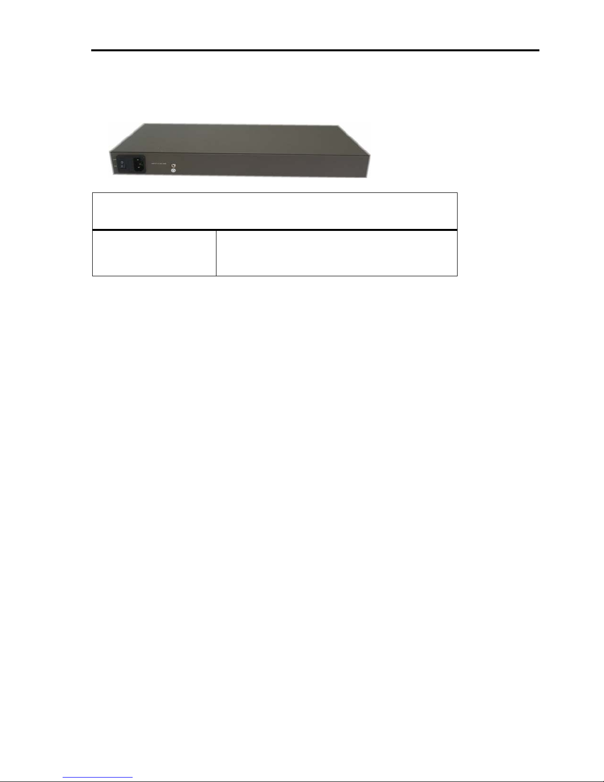
3.1.2 Rear Panel
2.1.2
Interface Description
INPUT 85-265 VAC Input Voltage 230 VAC
2.2 Unpacking the DRO-250i
DRO-250i Package Contents
The DRO-250i package contains the following items:
• The DRO-250i router
• 1 Blue cross-over Ethernet Cables
• 3 Grey Straight Ethernet Cables
• 1 V.35 Cables
• 1 power cord
• User Manual (CD)
• Quick Install Guide
DRO-250i User Manual
15
Page 17

Installing DRO-250i
2.2.1
3.1.3 Mounting the DRO-250i
The DRO-250i can be mounted on any stable surface. It requires 1 U of
vertical space in the rack. The DRO-250i Router can be installed as a
standalone unit on any stable surface. For standalone, make sure the unit
has at least 1.5 in. (3.75 cm) of clearance on each side to allow for
adequate airflow and cooling.
Dimensions
440.96 x 194.81 x 44 mm
(Rack mount, 1U standard)
Weight
2.5 Kg.
Power requirements
• Power consumption: 6.6W
• AC input voltage: 85 to 265 VAC
• AC input current: 1.6 A
• Frequency: 50 Hz
Environmental specifications
• Operating Temperature: 32 to 104
• Storage Temperature: -13 to 158
• Humidity: 5 to 95% non-condensing
0
F (0 to 55 0 C)
0
F (-25 to 70 0 C)
DRO-250i User Manual
16
Page 18
Introduction to DRO-250i
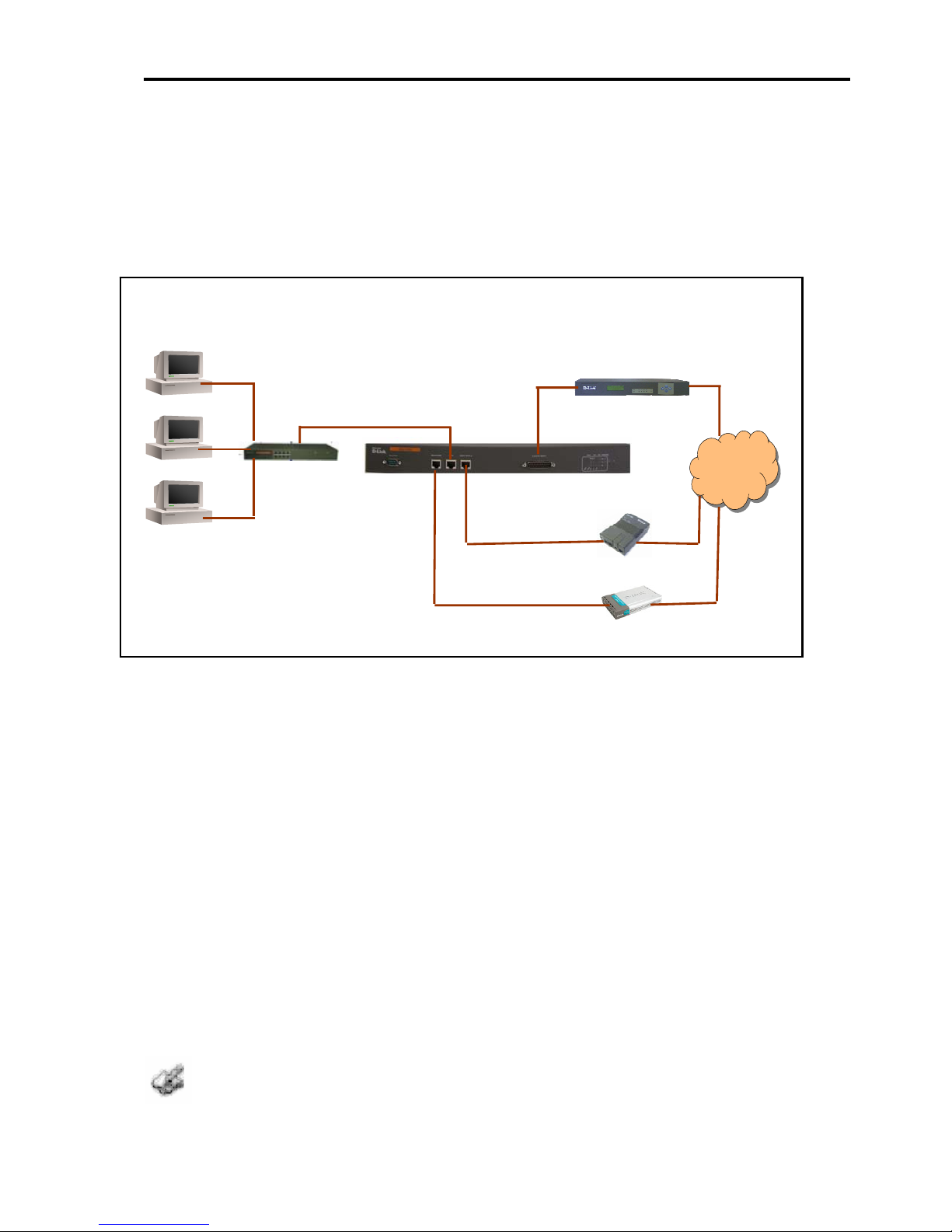
2.3 Connecting the DRO-250i to your network
Once the initial configuration of the DRO-250i is completed, you can
connect the DRO-250i between your internal network and the internet
.
Internal Network
DRO-250i
LAN
Hub or switch
WAN 3
DLM-G2100V
Internet
DNT-NT1
GLB-502T
• Make the necessary power connections. The power LED will turn ON
to indicate proper operation.
• Connect the LAN interface to the hub or switch connected to your
internal network using cross cable.
• Connect the V.35 DTE WAN Port to a 2 Mbps Leased-Line modem.
• Computers that act as servers (Mail Server, FTP Servers etc) to provide
Internet services should be connected to DMZ Port using an Ethernet
Cable.
• Connect the WAN2 interface to the ISDN NT1.
• Connect an analog modem to the Aux Port.
Power-OFF before inserting the V.35 cable
DRO-250i User Manual
17
Page 19
Installing DRO-250i
2.4 Configuration via Web Browser
With some advance preparation, it’s easy to install DRO-250i and begin
using it. The following topics have been organized as a set of guidelines to
ensure that your computer and your network are ready for it.
1. This Router is a ready to use flash programmed board. (The Image is
loaded on to the flash).
2. Router supports WEB based management feature to configure the
board. Internet Explorer (Version 5.5 and above) is the preferred browser.
Connect the PC to the LAN port of Router and open internet explorer
browser with the following
“https://<IP address > of Router’s LAN interface ” i.e.
https://<192.168.100.254 > connection on Internet Explorer. This will
bring the login page of Router on the browser.
Default LAN IP is 192.168.100.254 (User can change this IP address
using Web).
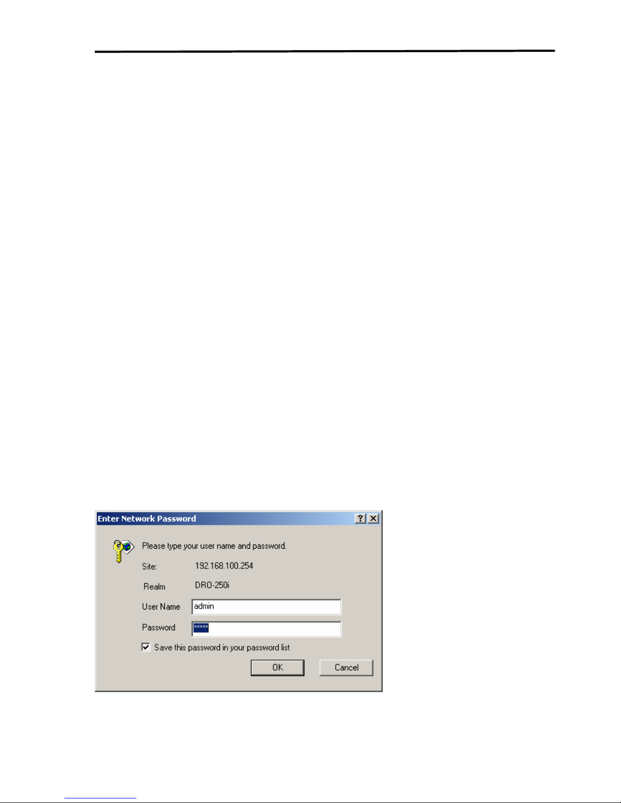
3. It will ask for username and password.
User name: “admin”
Password: “admin”
DRO-250i User Manual
18
Page 20
Introduction to DRO-250i
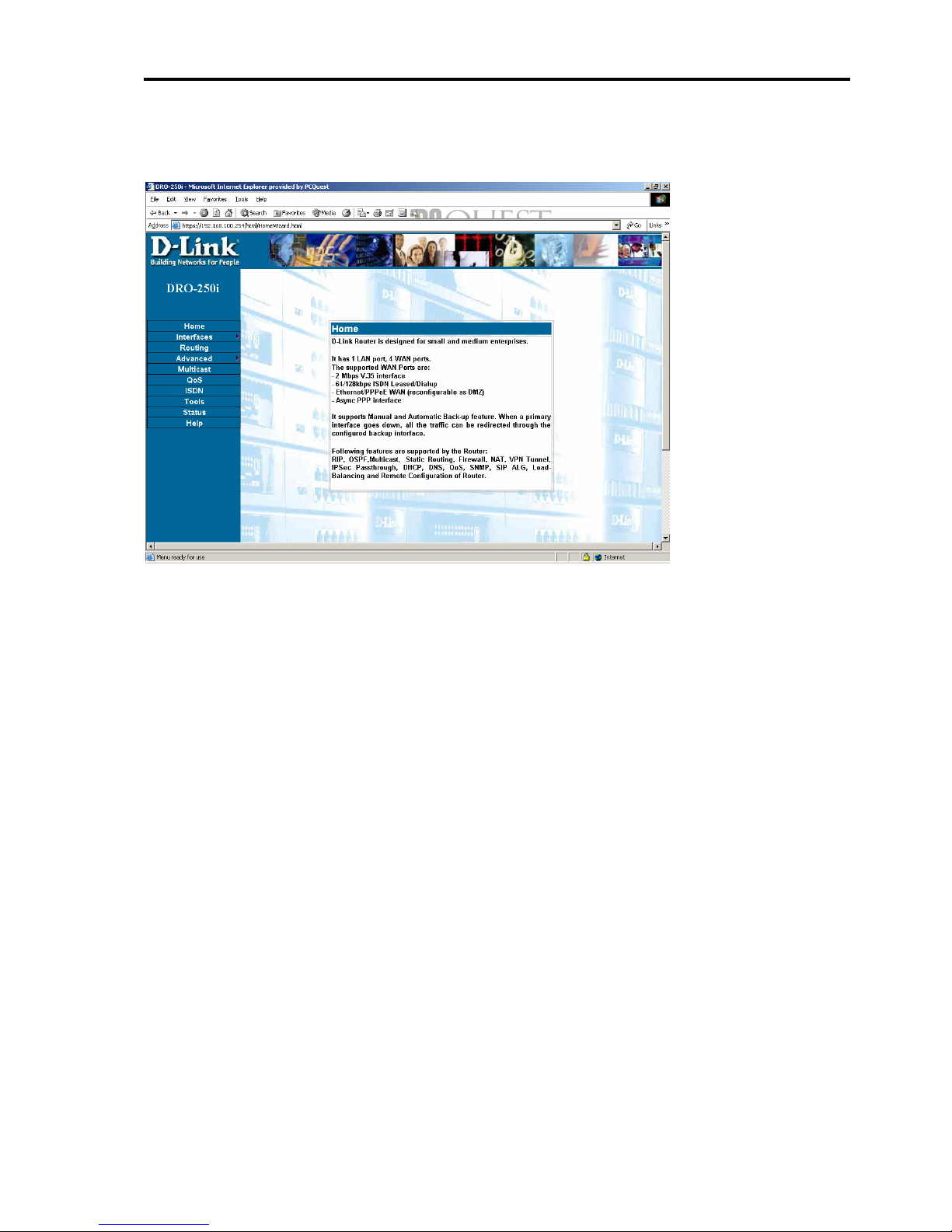
D-Link Welcome Page will appear and you can browse through the web
page.
DRO-250i User Manual
19
Page 21

Introduction to DRO-250i
CHAPTER3
CONFIGURATION THROUGH WEB
The Web configuration is simple and easy to use. It will help in quick
setting of the Router to connect to ISP (Internet Service Provider) with
few steps required. It will guide user step by step to configure the
password and WAN settings of DRO-250i.
3.2 INTERFACES
3.2.1
INTERFACES-LAN
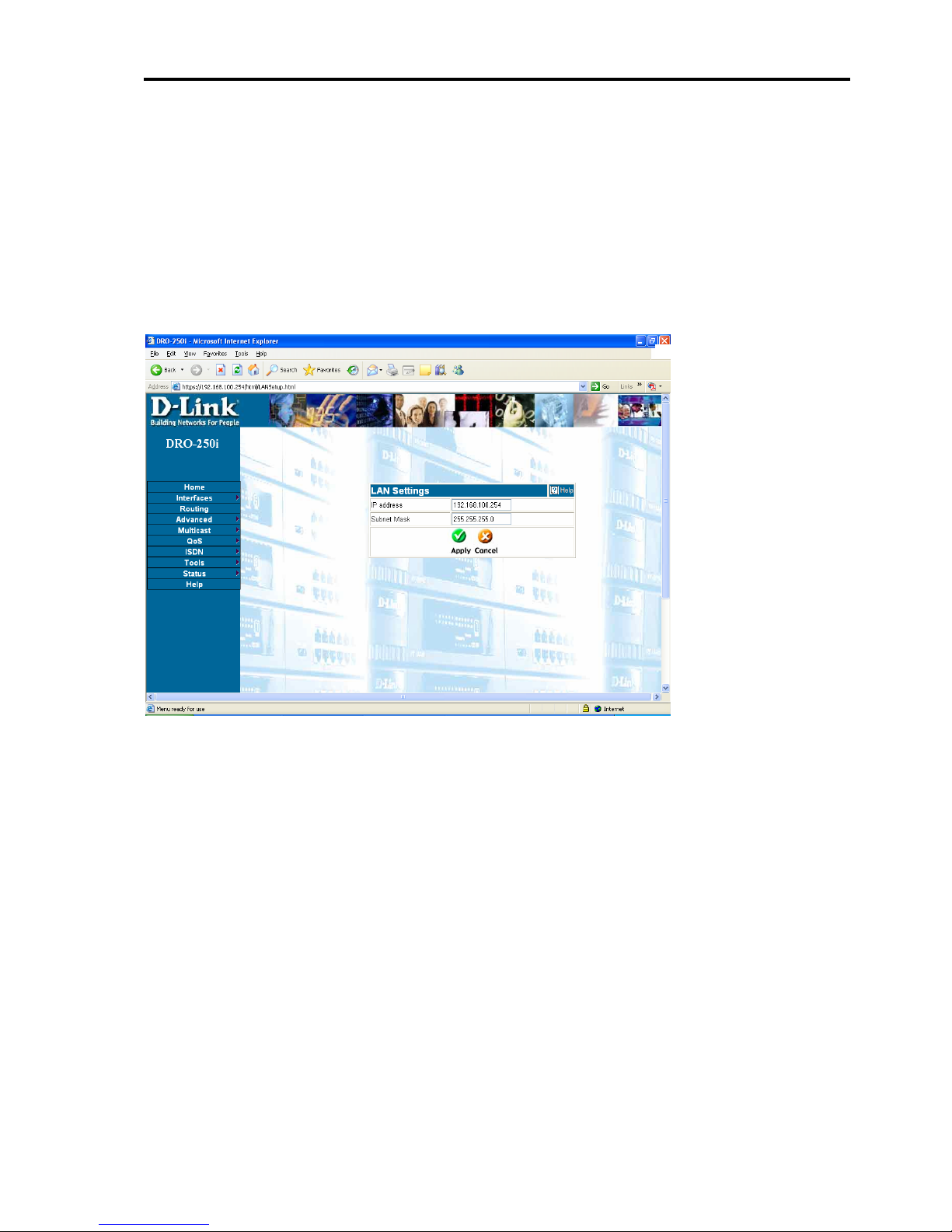
The LAN Settings allows user to view the current IP address and subnet
mask assigned to the Router. It also allows user to change these settings.
If it is necessary to change the IP address or subnet mask assigned to the
Router, enter the new values in the appropriate fields and then click apply
to make the current changes.
For an example, if LAN network is to be a 192.168.0.x network with a
subnet mask of 255.255.255.0, user might assign the Router an IP address
of 192.168.0.1 and configure its DHCP server to assign addresses in the
range between 192.168.0.2 to 192.168.0.100. The default gateway setting
for computers on the LAN side will be the DRO-250i’s IP address which
in this case is 192.168.0.1.
Saving all of this information to the DRO-250i's flash and restarting it will
make this IP addressing scheme current. In Windows, when the user
enables DHCP on the NIC he/she will obtain an IP address automatically,
upon restarting the computer(s) connected on the LAN side of the Router.
User’s computer(s) will automatically be assigned an IP address (es) from
the range 192.168.0.2 to 192.168.0.100. As an alternative, user could
disable the DHCP server and manually update the IP address, subnet mask
and default gateway information for each computer on the LAN side.
DRO-250i User Manual
20
Page 22
Introduction to DRO-250i
It is recommended that if user needs to change the IP addressing scheme
for the Router, he/she can configure its DHCP server with the appropriate
IP address range an d subnet mask, and then assign an IP addres s from the
same range. This way, a computer on the LAN side of network can always
get the proper network addressing information by DHCP from the Router
simply by being restarted.
Click on Interface > LAN to get the web page as shown below:
DRO-250i User Manual
21
Page 23
Configuring DRO-250i
3.2.2 INTERFACES - WAN 1
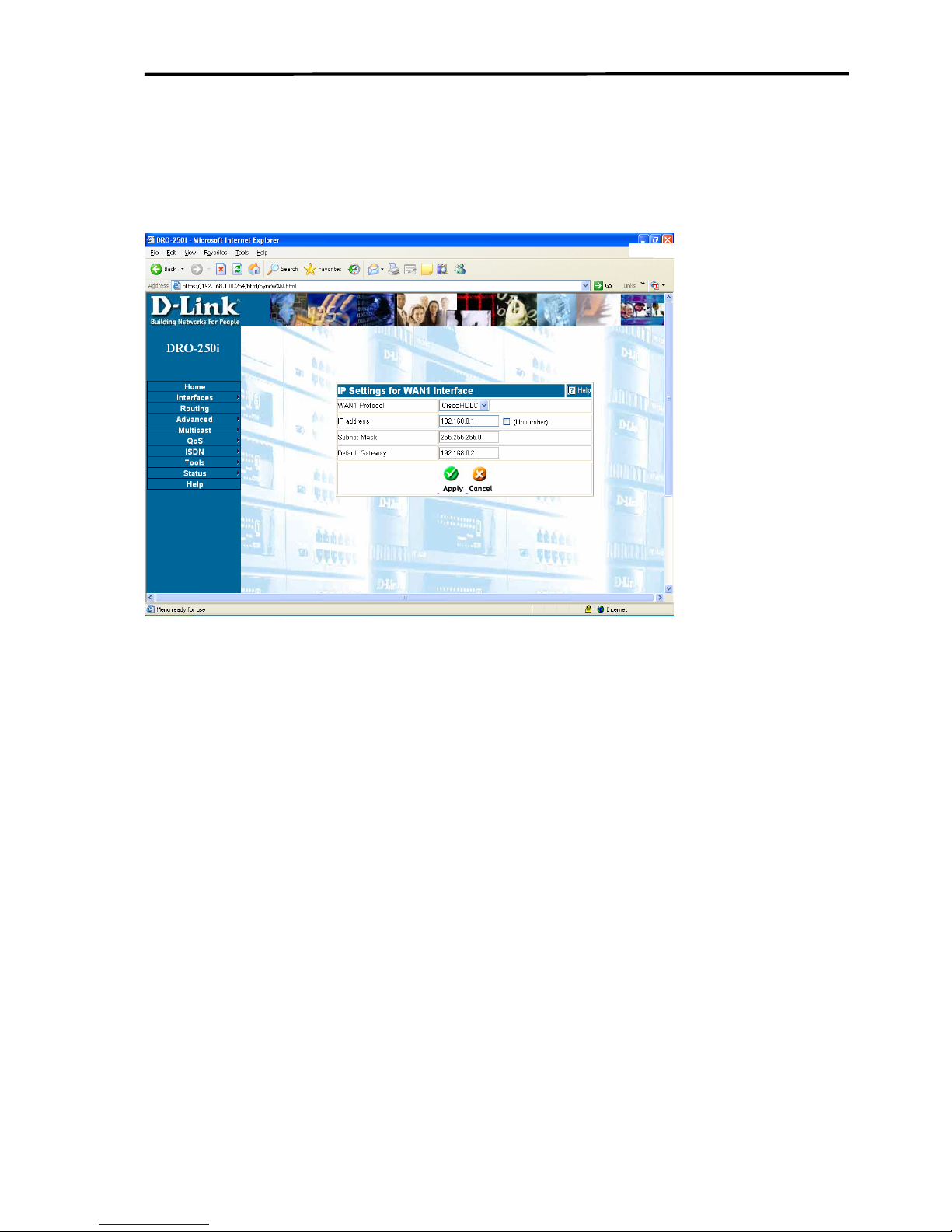
For WAN1 settings Click on Interfaces > WAN1 and the web page opens
as shown below:
User will need to enter the IP address, subnet mask, gateway address and
DNS address(es) provided to user by ISP. Each IP address entered in the
fields must be in the appropriate IP form, which is four IP octets separated
by a dot (x.x.x.x). The Router will not accept the IP address if it is not in
this format.
Protocol: CiscoHDLC/Sync PPP user can select the sync protocol which
can be either cisco HDLC or Sync PPP. User should confirm the protocol
supported by the ISP and then configure accordingly.
DRO-250i User Manual
22
Page 24
Introduction to DRO-250i
3.2.3 INTERFACES – WAN2
3.2.3.1 Mode Settings
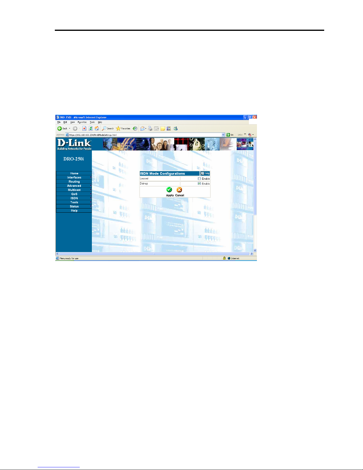
Click on Interfaces > WAN2 > Mode Settings and the web page open as
shown below:
This page allows user to configure ISDN in either Leased or Dialup. If the
user selects Leased on this page and clicks apply then only leased
configuration page will be shown. If user wants to configure for dialup
then he/she has to select dialup from this page and then click apply.
DRO-250i User Manual
23
Page 25
Configuring DRO-250i
3.2.3.2 WAN2-Dial Up
3.2.3.2.1 Dial Up-Connection Settings
This page allows the user to select different types of connection settings
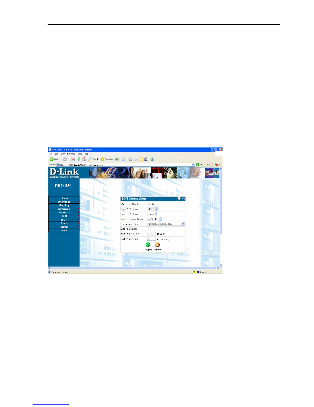
i.e. 64 kbps, 128 kbps etc. On this page if the connection type is changed
then again appropriate pages (ISP or DIALIN configuration pages or both)
needs to be applied depending on the new connection type selected.
Click on Interfaces > WAN2 > Dial up > Connection Settings and the
web page open as shown below:
My Phone Number:
“My Phone number” is user's own telephone number with an area code
included if ISDN port is directly connected to the phone socket. Otherwise
if it is connected to a PBX, then provide the MSN (phone number) stored
in the PBX. E.g.: If the area code of user is 080 and phone number is
26788835 then enter 08026788835 in this field. It can be of maximum 14
digits.
DRO-250i User Manual
24
Page 26

Introduction to DRO-250i
This field must be filled with proper values as mentioned above to support dial-
in.
Layer 2 Protocol:
For this protocol, the parameter is set as HDLC.
Layer 3 Protocol:
For this protocol, the parameter is set as Transparent.
Packet encapsulation:
For this protocol, the parameter is set as Sync PPP.
Connection Type:
Users can select among the available connection types in the dropdown
list depending on his/her requirement.
128K Dialin/Dialout-User can configure dial out and dial in 128k.
64K Dialin + 64K Dialout-User can configure first channel (B1) for dial
out and second channel (B2) for dial in.
2-64K Dialout-Users can configure two channels (B1& B2) with two
different dialout configurations.
2-64K Dialin-Users can configure two channels (B1& B2) with two
different dialin configurations.
BOD Dialout-User can configure Bandwidth on demand for dialout
configuration.
Dial On Demand:
Dial on demand feature allows the system to dial automatically whenever
there is traffic on the WAN2 interface. This feature will be enabled only
when the connection type is 64kbps dial in & dialout or 2-64kbps dialout
or BOD dialout.
DRO-250i User Manual
25
Page 27

Configuring DRO-250i
High Water Mark and High Water Time:
These parameters specify the conditions under which the second channel
will be activated. When the utilization of the first connected channel goes
over the High Water Mark and passes the High Water Time, the additional
channel will be activated. The link speed will then be 128kbps .
The default value for High water mark is 56 kbps and the default value for
High water
These parameters are enabled only when connection type is BOD (Bandwidth
On Demand). Default values highwater mark and highwater time are 7000 bytes
and 30 seconds respectively
.
Automatic applying of ISDN pages:
Whenever user clicks on apply in the ISDN Connection page, then
depending upon the connection type automatically dialout and dialin pages
will be applied.
Automatic apply of dialout pages: Dialout page will be applied with
appropriate profile if he/she has configured it previously. User has to
configure profile for each connection type (i.e. 64K B1, 64K B2 and
128K) at least once.
-If user has selected connection type as 128K dialin/dialout or BOD
dialout and he has configured a profile for this connection type then that
profile will automatically be applied.
-If user has selected connection type as 64kdialin+64kdialout and he has
configured a profile for channel B1 that profile will be applied
automatically.
- If user has selected connection type as 2 64kdialout and he has
configured profiles for both channel1 (B1) and channel2 (B2) then those
profiles will automatically be applied.
Automatic apply of dialin pages: Dialin page is automatically applied
with appropriate profile if they are configured previously.
-If user configured profile for B1 previously then when user selects
connection type 128K dialin/dialout or 2 64Kdialin then B1’s profile will
DRO-250i User Manual
26
Page 28
Introduction to DRO-250i
automatically be applied
-If user has configured channel B2 then when user selects connection type
64KDialin+64KDialout or 2 64Kdialin it will automatically be applied.
Automatic apply of mode settings: Suppose if user has selected leased
and press apply on the mode settings page then leased page will be applied
automatically if it was configured previously. Same, if user selects dialup
in mode settings page and press apply
then ISDN dialup
pages(connections page, dialout, dialin) will be automatically applied if
they were configured previously.
3.2.3.2.2 Dial Up-Dial out
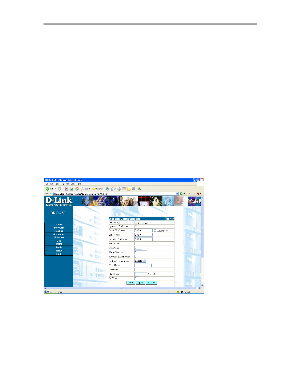
Click on Interfaces > WAN2 > Dialup > Dial Out and the web page
open as shown below:
This page has the parameters required for establishing the internet
connection with the ISP. This page enables the user to configure the
channels with ISP configurations depending upon the connection type he
chooses from ISDN connection settings page. User can add a maximum of
DRO-250i User Manual
27
Page 29

Configuring DRO-250i
five different ISP profiles on this page and depending upon the choice
he/she can configure channels with those profiles. Profiles are independent
of channels; user can configure any profile on any of the channels. ADDbutton enables the user to add the profile into the profiles table. APPLYbutton enables the user to apply the selected configuration on the selected
channels. To apply a particular configuration from the saved profiles user
should click on View and select the channel and click Apply. Selection of
channel depends upon the connection type the user chooses from the
ISDN connections page. User can choose either B1 or B2 only when
connection type is 2-64K dialout. For all other Connection types B1
channel is selected automatically. When the Connection type is 128kbps
dial out/dial in only Channel 1(B1) will be enabled .User can see the
status of two channels in the status page. Profile table will show which
profile has been selected for which channel. This page only configures the
particular channel with ISP profile. To initiate a dial go to ISDN STATUS
page and click Dial .
Local IP address:
Fill in the fixed IP address given by the ISP provider. It is in the form of
four IP octets separated by a dot (x.x.x.x).
Unnumbered:
This interface can be configured as an Unnumbered interface.
Net mask:
Enter the subnet mask in dotted decimal (i.e. A.B.C.D) format
Remote IP address:
Fill in the fixed IP address of the remote server given by the ISP. It is in
the form of four IP octets separated by a dot (x.x.x.x)..
Area Code:
It provides the Area Code of the ISP. e.g. area code of user is 080 and
ISP's area code is 022, then user should enter 22 in the area code field.
DRO-250i User Manual
28
Page 30

Introduction to DRO-250i
If the area code of user and the ISP is same, then enter zero in the area code
field.
Dial Prefix:
In Dial Prefix, user should enter the country code if the user is dialing to
other country, or else enter zero e.g. if user wants to dial to Singapore then
enter 0065 as dial prefix where 65 is country code of Singapore.
Phone Number:
Enter the phone number of the ISP, excluding the Area Code and Dial
Prefix.
Alternate Phone Number:
Enter the alternate phone number of the ISP, excluding the Area Code and
Dial Prefix. If primary phone number is busy then alternate phone number
will be dialed automatically.
User Name:
Enter the user name given by the ISP provider. It can be 20 characters
long.
Password:
Enter the password given by the ISP provider. It can be 20 characters
long.
Protocol Compression
This will enable or disable Protocol Compression field. This should be
same as ISP settings. Before enabling or disabling this field, verify ISP
settings and then select accordingly.
DRO-250i User Manual
29
Page 31
Configuring DRO-250i
Idle Timeout:
If there is no activity on the line then, the connection will hang-up
automatically after the time entered in Idle Timeout field in seconds. Enter
zero in this field to disable auto hang-up.
Retries:
Enter the number of times user wants the system to retry the dialing to
connect to ISP if it is not connected. It is a single digit number.
3.2.3.2.3 Dial Up-Dial In
Dial in
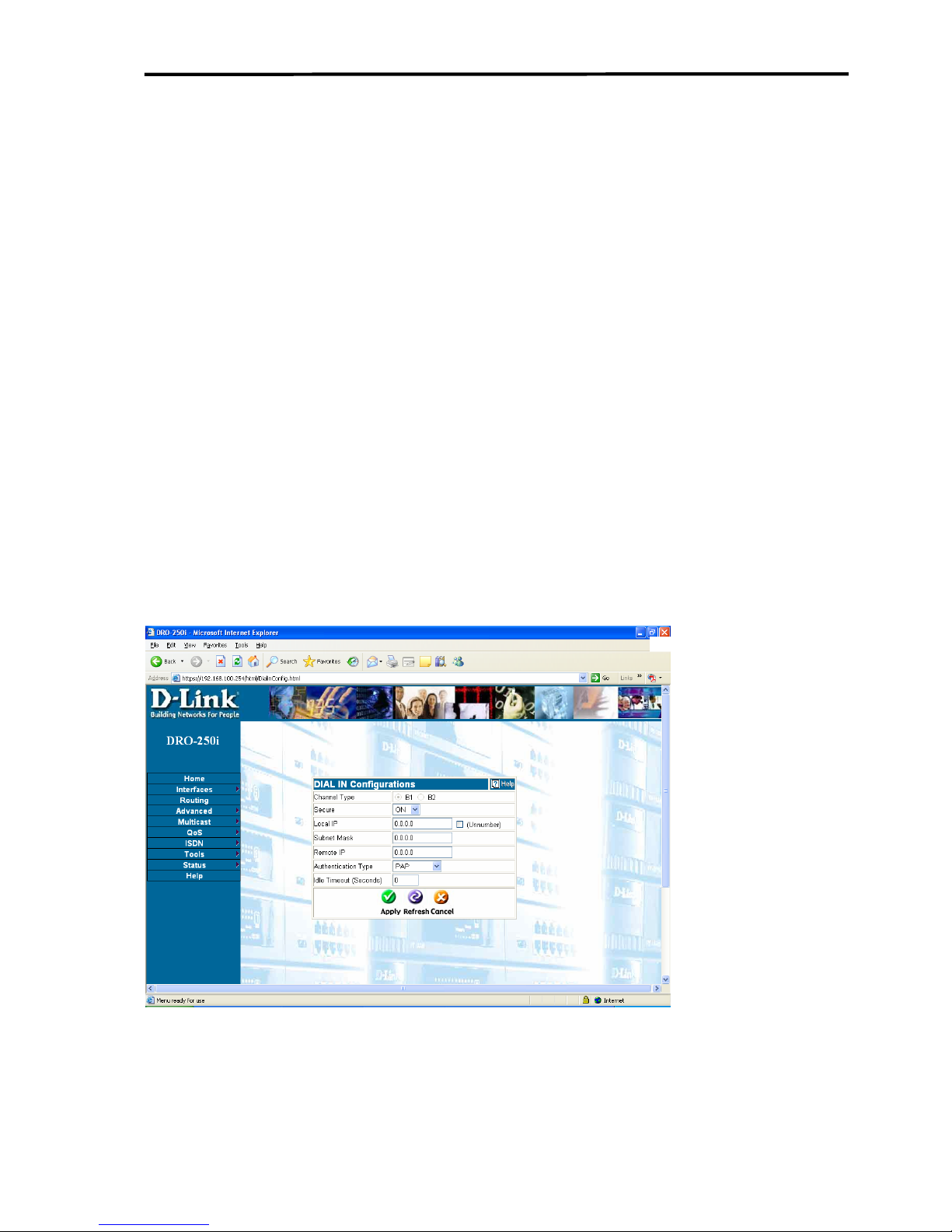
Click on Interfaces > WAN2 > Dial up > Dial in > Dial In and the web
page open as shown below
:
This page has the parameters required for establishing Dialin connection.
User can configure either channel 1 or channel 2 depending upon the
DRO-250i User Manual
30
Page 32

Introduction to DRO-250i
connection type he/she selects from the ISDN connections page. User can
select Channel 1(B1) or Channel 2(B2) only when the connection type is
2-64K Dial in. For all other connection types Channel 1(B1) will be
selected automatically. When the user clicks on the Channel 1 or Channel
2 he will get the information which he configured previously for the
particular channel.
Secure:
When ON is selected the Dialin connections are accepted only from the
phone numbers added in the Dialin User Accounts Page. If OFF is
selected then Dialin connections will be accepted from any phone
number.
Local IP:
Enter the IP address to be assigned for the Dialin connection one at end. It
is in the form of four IP octets separated by a dot (x.x.x.x).
Unnumbered:
This interface can be configured as an unnumbered interface.
Netmask:
Enter the subnet mask in dotted decimal (i.e. A.B.C.D) format.
Remote IP
Enter the IP address to be assigned to the remote end for the Dialin
connection. It is in the form of four IP octets separated by a dot (x.x.x.x).
Authentication
Select the PAP or CHAP depending on what the other end is using. Try
PAP/CHAP only when user is not sure what the other end is using.
Idle Timeout (In seconds)
If there is no activity on the line the connection gets disconnected after the
time entered in this field in seconds.
DRO-250i User Manual
31
Page 33
Configuring DRO-250i
User Account
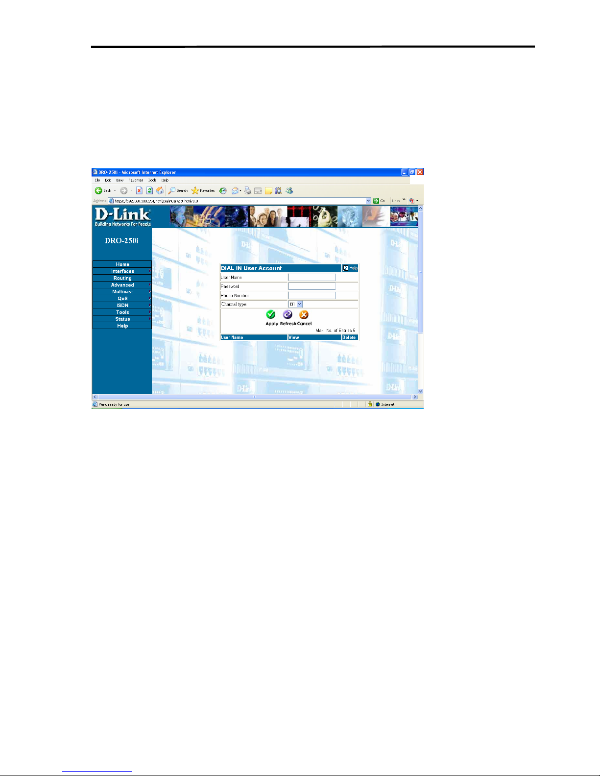
Click on Interfaces > WAN2 > Dial up > Dial in > User Account and
the web page open as shown below:
This page allows configuring User Account for Dialin connections.
User Name:
Enter the user name to be given to Dialin user. It can be 20 characters
long.
Password:
Enter the password to be given to the Dialin user. It can be 20 characters
long.
Phone Number:
Enter the phone number of the Dialin user including area code, for e.g. if
the Dialin user area code is 080 and phone number is 26788345 then enter
08026788345 in this field. This number is used to allow Dialin
connection, in case the SECURE option on this page is set to ON.
DRO-250i User Manual
32
Page 34
Introduction to DRO-250i
Channel Type:
User can select channel type in this page so that he can restrict some user
dialing on particular channel.If he selects channel1 then username and
password will be allowed on that channel only.
If user has selected connection type 128K dialin/dialout then he
can enter a user account on channel1 .
If user has selected connection type 64kdialin+64kdialout then
user should enter a user account on channel2.
If user has selected connection type 2-64kdialin then he can
enter two different phone numbers on two channels.
3.2.3.3
WAN2-Dial
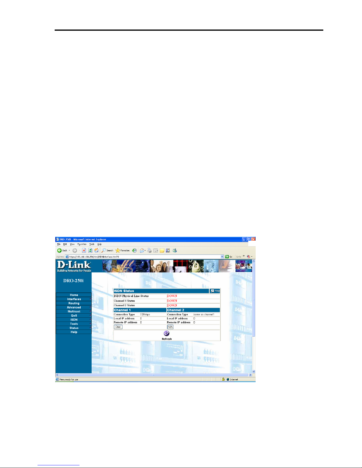
Click on Interfaces > WAN2 > Dial and the web page opens as shown
below:
Physical Line Status: This will show UP when D-Channel is up
otherwise it will show DOWN .
DRO-250i User Manual
33
Page 35

Configuring DRO-250i
Channel 1 Status: This will show UP when Channel1 (B1) is up
otherwise it will show DOWN.
Channel 2 Status: This will show UP when Channel2 (B2) is up
otherwise it will show DOWN.
Channel 1 and Channel 2 Status
Connection Type: This will show the connection type and whether
channel is being used as dial out or dial in.
Local IP address: This will show Local IP address.
Remote IP address: This will show Remote IP address.
DRO-250i User Manual
34
Page 36
Introduction to DRO-250i
3.2.4 INTERFACES –WAN3
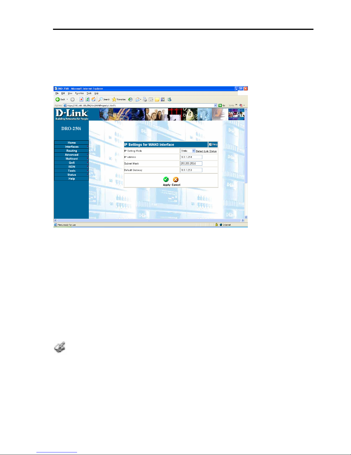
Click on Interfaces > WAN3 and web page opens up as shown below:
WAN3 Settings
The WAN3 Settings menu allows you to view the current configuration
for your DRO-250i, and to choose the protocol by which your DRO-250i
will receive its WAN3 network settings
WAN3 Settings - Static IP address
Select this option to set static IP information. You will need to enter the IP
address, subnet mask and gateway address provided to you by your ISP.
The default gateway field specified here will be used by Load balancing feature
to route packets through this interface.
.
DRO-250i User Manual
35
Page 37
Configuring DRO-250i
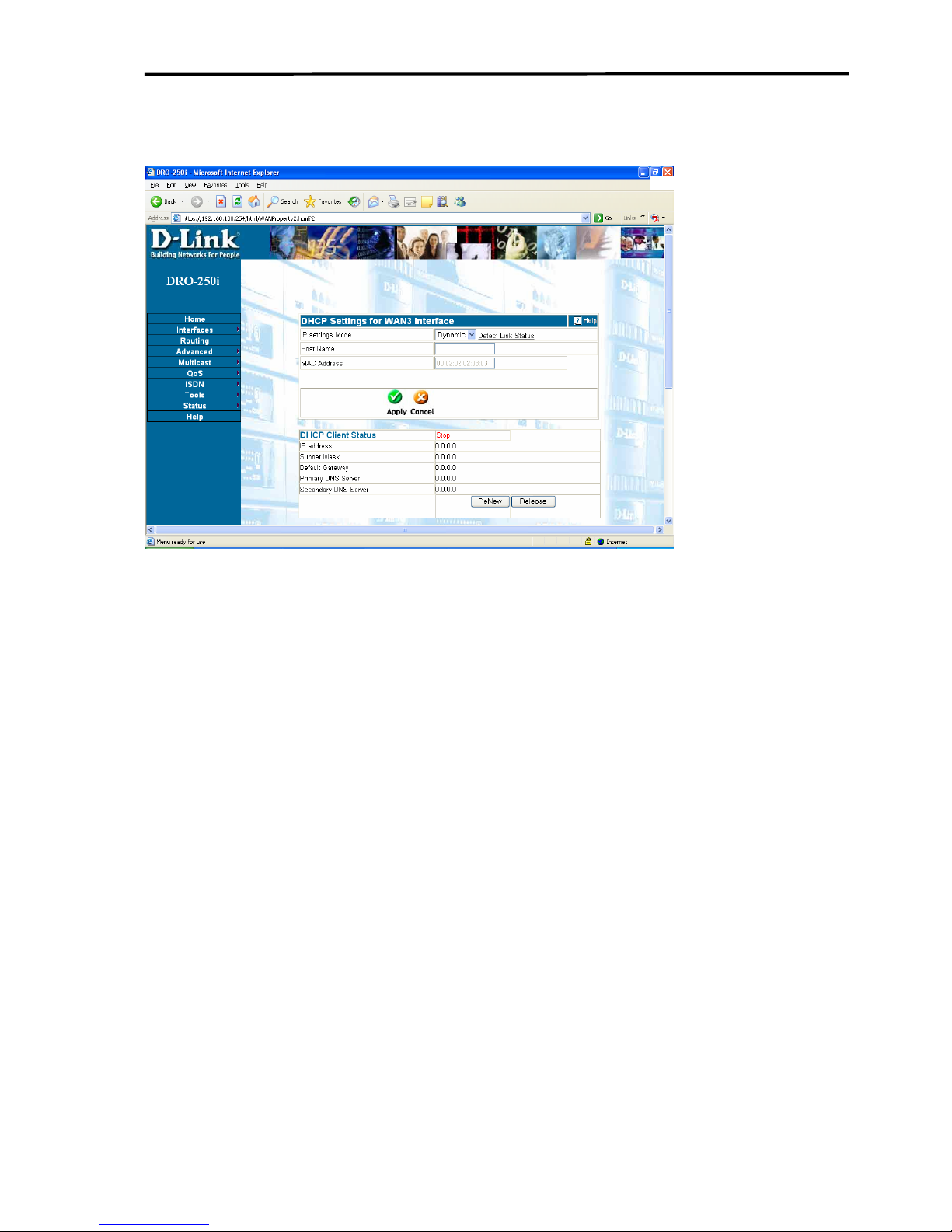
WAN3 Settings - Dynamic IP address
Select this option if your ISP provides you an IP address automatically.
This option is typically used for Cable services. Dynamic IP address
allows the DRO-250i to get its IP address information from your ISP using
the Dynamic Host Configuration Protocol (DHCP). Use this setting if your
ISP instructs you to use DHCP or to automatically obtain an IP address. A
server on your ISP's network will then automatically send the necessary IP
address information to your DRO-250i.
Host Name: Hostname is the name assigned to the DRO-250i which will
be displayed in the DHCP server list to which the device is connected.
Renew /Release: Renew button will help the user to get an IP address
from the DHCP server. If user wants to release the current IP address, then
click on release button.
DRO-250i User Manual
36
Page 38
Introduction to DRO-250i
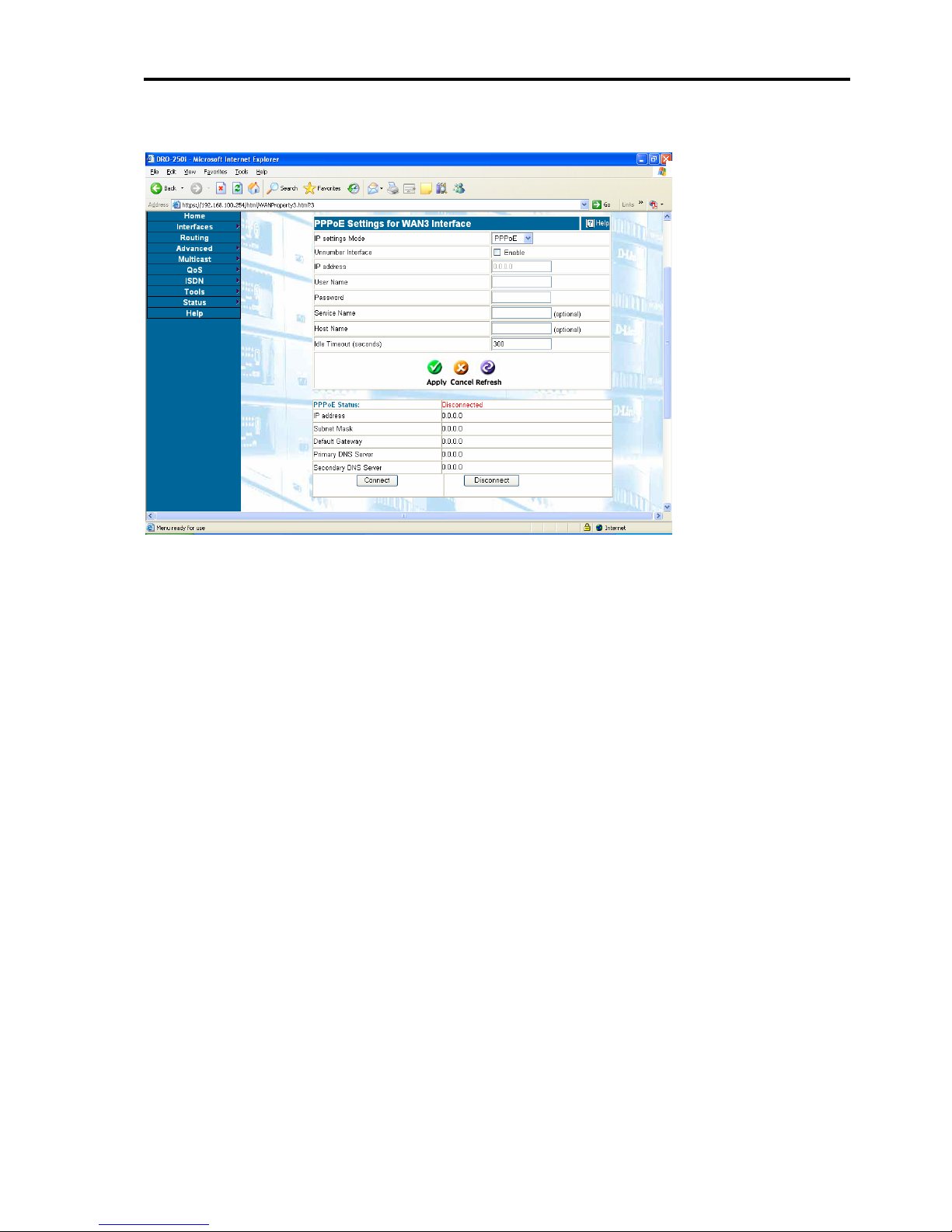
WAN3 Settings – PPPoE
PPPoE stands for Point-to-Point Protocol over Ethernet. Select this option
if your ISP requires you to use a PPPoE connection. This option is
typically used for DSL services.
Unnumber Interface - This interface can be configured as an
Unnumbered interface. When this is not selected, DRO-250i will obtain an
IP address automatically for your PPPoE connection.
User Name - Enter your PPPoE username.
Password - Enter your PPPoE password.
Idle Timeout (In seconds) - This is the time interval which if there is no
network traffic between your local network and your ISP, your PPPoE
connection will be disconnected.
Host Name: Hostname is the desired access concentrator's name. If there
is no access concentrator present with this host name, then client will
choose any one which is available.
DRO-250i User Manual
37
Page 39

Configuring DRO-250i
Service Name - Enter the service name provided by your ISP. (optional)
Connect/Disconnect: User has to click on connect button after applying
the PPPoE settings. And user has to click on disconnect button if he/she
wants to discontinue the connection. If user has configured WAN3 as
static or dynamic, then user should apply the PPPoE settings before
clicking on connect button.
Option to choose DMZ/Ethernet WAN
DRO-250i users can use the same physical port as DMZ or Ethernet
WAN, called WAN3. User can check the option he/she wants. After
checking the proper option i.e. DMZ or Ethernet WAN, the physical port
will behave in that manner.
For example, if currently the port is working as DMZ port, then user can
check the option of Ethernet WAN and click on Apply Button. After
clicking on Apply button, the port will start behaving as Ethernet WAN. It
works vice versa too.
Unnumbered Interfaces
Only point-to-point interfaces can be configured as an unnumbered
interface. An unnumbered interface, borrows the LAN IP address by
default. The user can edit this and configure a custom IP address on the
unnumbered interface. The subnet mask for an unnumbered interface is
always 255.255.255.255. For Dialup interfaces, the Remote IP field will
be disabled and determined only through negotiation. When NAT is
enabled on an unnumbered interface, local services (such as DNS Proxy
etc) may be affected
. To overcome this problem, configure one of the
Global IP addresses from the NAT pool as the unnumbered interface's IP
address.
Routers at both ends of the point-to-point link should be configured to be
unnumbered
.
DRO-250i User Manual
38
Page 40
Introduction to DRO-250i
3.2.5 INTERFACES – WAN 4
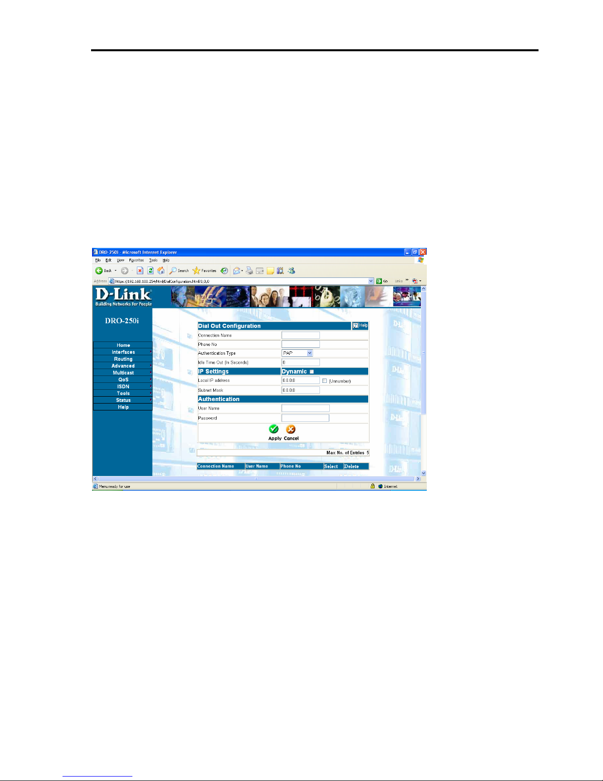
3.2.5.1 WAN 4 - Dial Out
Dial Out configuration is used for connecting a remote host using modem
and telephone cable. For this it will require some basic information such
as connection name, telephone number, user name and password.
Click on Interfaces > WAN4 > Dial Out and web page opens up as
shown below:
Connection Name: User must give the account a name. This can be
anything user likes, but if user has more than one account, each name must
be unique.
Phone No: Specify the phone number to dial
Authentication type: Password Authentication Protocol (PAP): The
client authenticates itself by sending a user name and an (optionally
encrypted) password to the server, which the server compares to its secret
database. Challenge Handshake Authentication Protocol (CHAP): The
authenticator (i.e. the server) sends a randomly generated ``challenge''
string to the client, along with its hostname. The client uses the hostname
DRO-250i User Manual
39
Page 41

Configuring DRO-250i
to look up the appropriate secret, combines it with the challenge, and
encrypts the string using a one-way hashing function. The result is
returned to the server along with the client's hostname. The server now
performs the same computation and acknowledges the client if it arrives at
the same result choosing the appropriate method of authentication that can
be used to log onto the server.
Check your provider for more info.
Idle Timeout (In Seconds): If there is no activity on the line then, the
connection gets disconnected after the time entered in this field
.
IP Settings: Check this if ISP uses dynamic IP address assignment. In this
case, IP address will change every time user establishes a connection.
Otherwise uncheck it
¾ If ISP has given user a static IP address. Then user will need to enter
that address in the IP address field and fill the appropriate subnet
mask.
Unnumbered: This interface can be configured as an unnumbered
interface.
User Name: Enter the user name for authentication.
Password: Enter the Password for authentication.
DRO-250i User Manual
40
Page 42
Introduction to DRO-250i
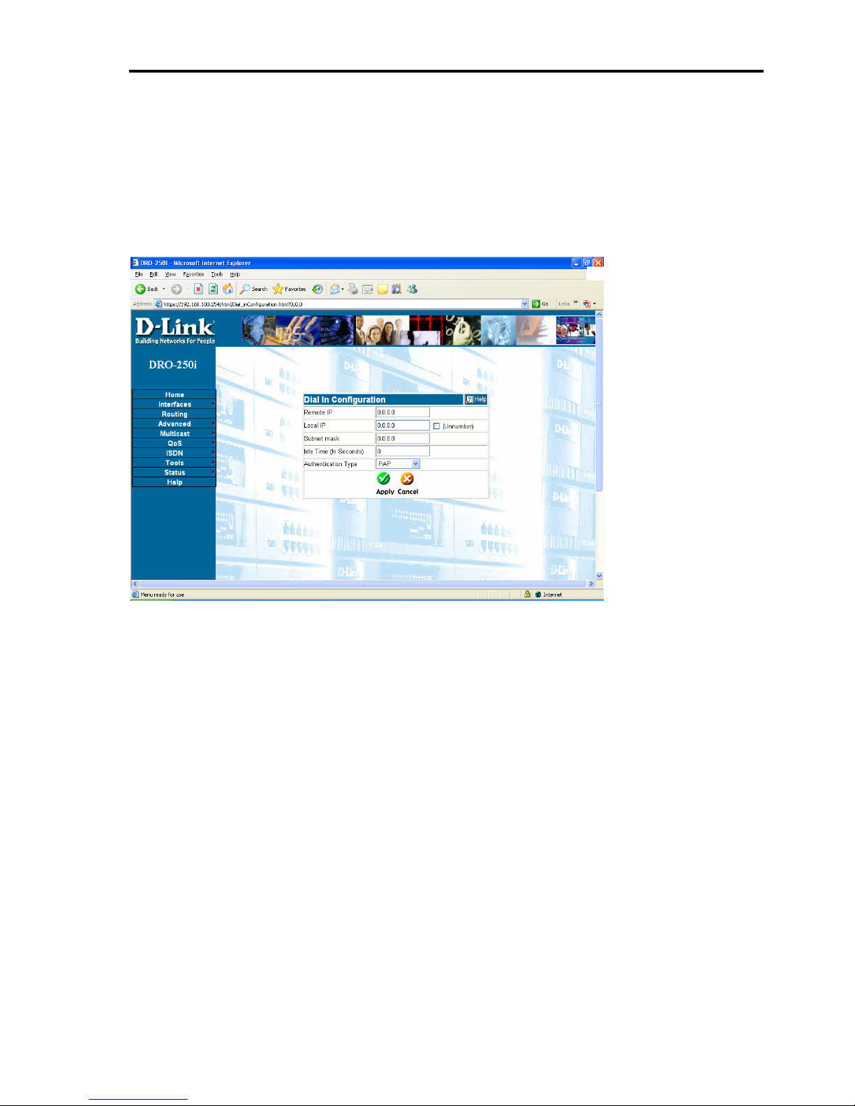
3.2.5.2 WAN 4 - Dial In Configuration
This page has the parameters required for establishing Dial-In connection
Click on Interfaces > WAN4 > Dial In Configuration and page opens up
as shown below:
Remote IP: Enter the IP address to be assigned to the remote end for the
Dial-In connection. It is in dotted decimal (i.e. A.B.C.D) format.
Local IP: Enter the IP address to be assigned for the Dial-In connection. It
is in dotted decimal (i.e. A.B.C.D) format
Unnumbered: This interface can be configured as an unnumbered
interface.
Idle Time (In Seconds):
If there is no activity on the line then, the
connection gets disconnected after elapsing of the time entered in this
field.
Authentication: Select PAP or CHAP depending on what the other end is
using. Select PAP/CHAP only when users are not sure what the other end
is using.
DRO-250i User Manual
41
Page 43
Configuring DRO-250i
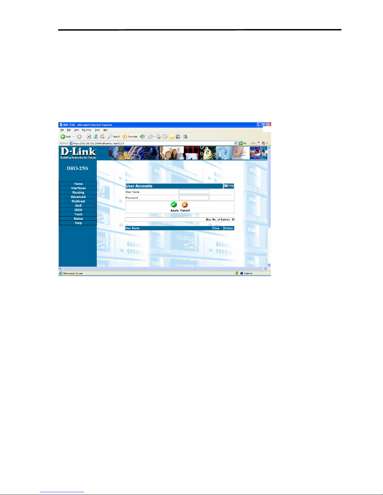
3.2.5.3 WAN 4 - Dial In User Account
This page allows configuring user accounts for Dial-In connections.
Click on Interfaces > WAN4 > Dial In User Account and page opens up
as shown below:
User Name: Enter the user name to be given to Dial-In user. It can be of
20 characters long.
Password: Enter the password to be given to the Dial-In user. It can be of
20 characters long.
DRO-250i User Manual
42
Page 44
Introduction to DRO-250i
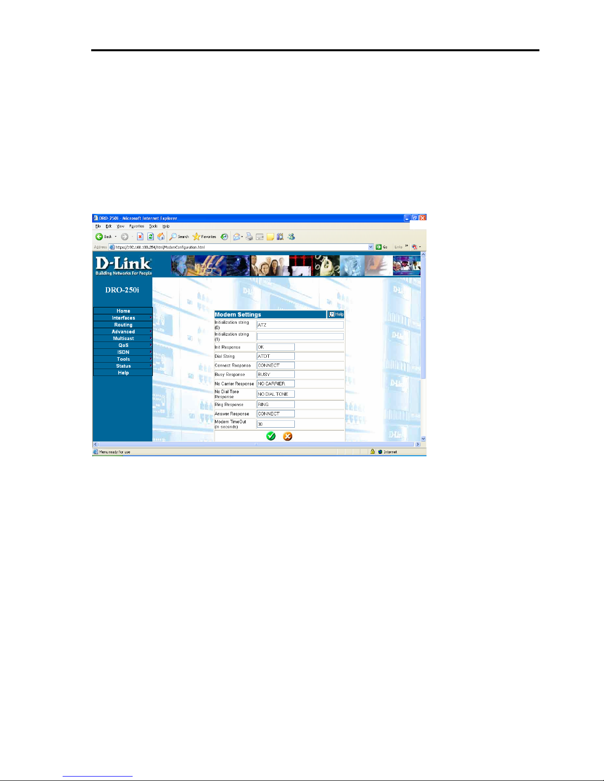
3.2.5.4 WAN 4 - Modem Configuration
Modem configuration is used for storing basic modem command
information which is specific to a modem.
Click on Interfaces > WAN4 > Modem Configuration and opens up as
shown below:
Initialization String (0): String used to initialize the modem. It is specific
for a modem. The default value is "ATZ".
Initialization String (1): If modem has two initialization strings then
provide second one, otherwise leave it blank.
Init Response: Provide Init response string for modem, the default value
is "OK".
Dial String: Provide dial command for modem, the default value is
"ATDT".
Connect Response: Provide connect response string for modem, the
default value is "CONNECT".
DRO-250i User Manual
43
Page 45

Configuring DRO-250i
Busy Response: Provide busy response string for modem, the default
value is "BUSY".
No Carrier Response: Provide no carrier response string for modem, the
default value is "NO CARRIER".
No Dial Tone Response: Provide no dial tone response string for modem
the default value is "NO DIAL TONE".
Ring Response: Provide ring response string for modem, the default value
is "RING".
Answer Response: Provide answer response string for modem, the default
value is "CONNE CT".
Modem Time Out: This is the time required to wait for the CONNECT
response from modem. A setting of about 30 seconds should be sufficient
for most purposes.
DRO-250i User Manual
44
Page 46
Introduction to DRO-250i
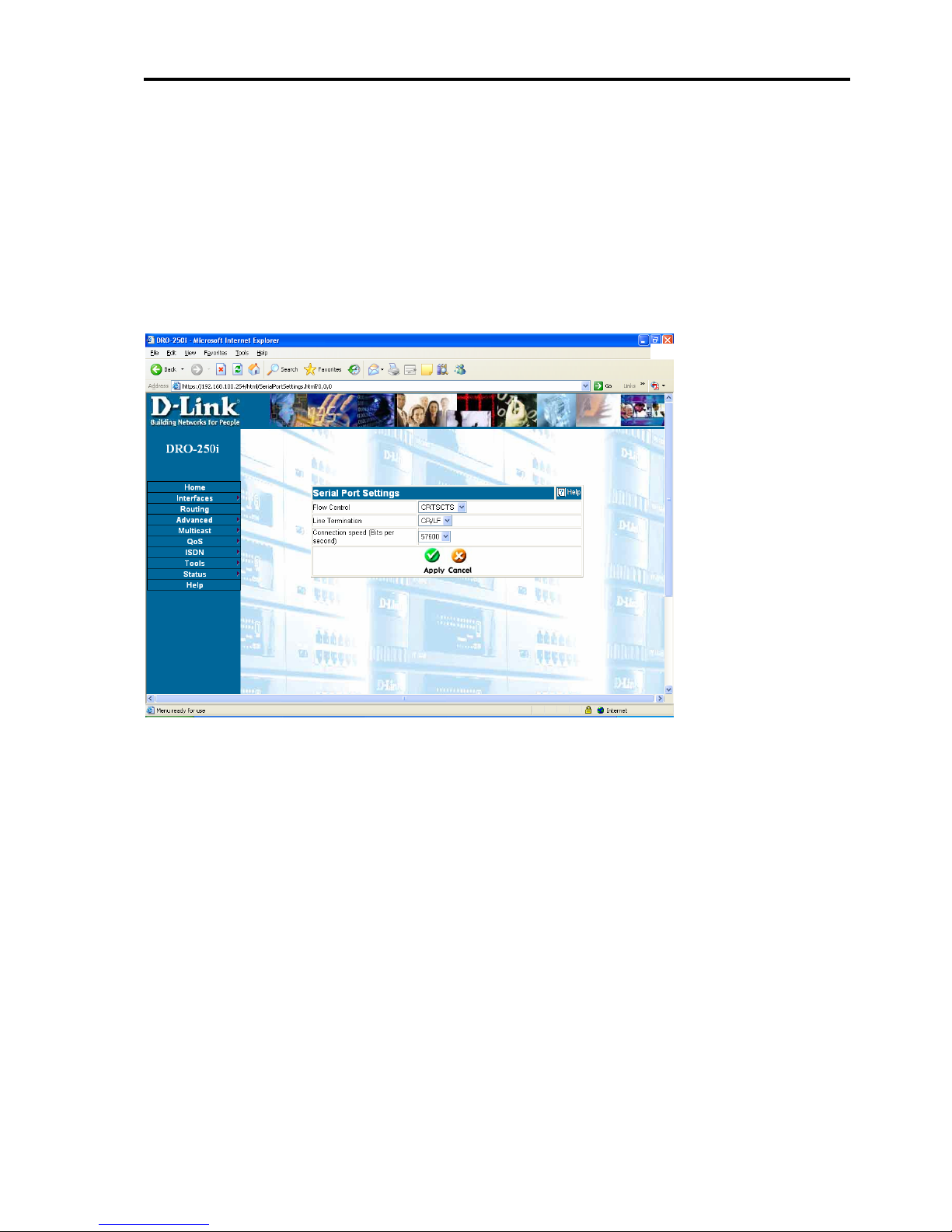
3.2.5.5 WAN 4 - Serial Port Settings
Information is required for initializing the serial port for asynchronous
Dial In/Dial Out
Click on Interfaces > WAN4 > Serial Port Settings and the web page
opens up as shown below:
Flow control: Select the appropriate flow control i.e. CRTSCT
(hardware), XON/XOFF (software) or NONE (no flow control). The
recommended setting is hardware flow control.
Line termination: Choose the correct character sequence for modem.
Most modems will use 'CR/LF’; however some modems need different
settings.
Connection speed (Bits per second): Choose from the list of connection
speed supported by serial port.
DRO-250i User Manual
45
Page 47
Configuring DRO-250i
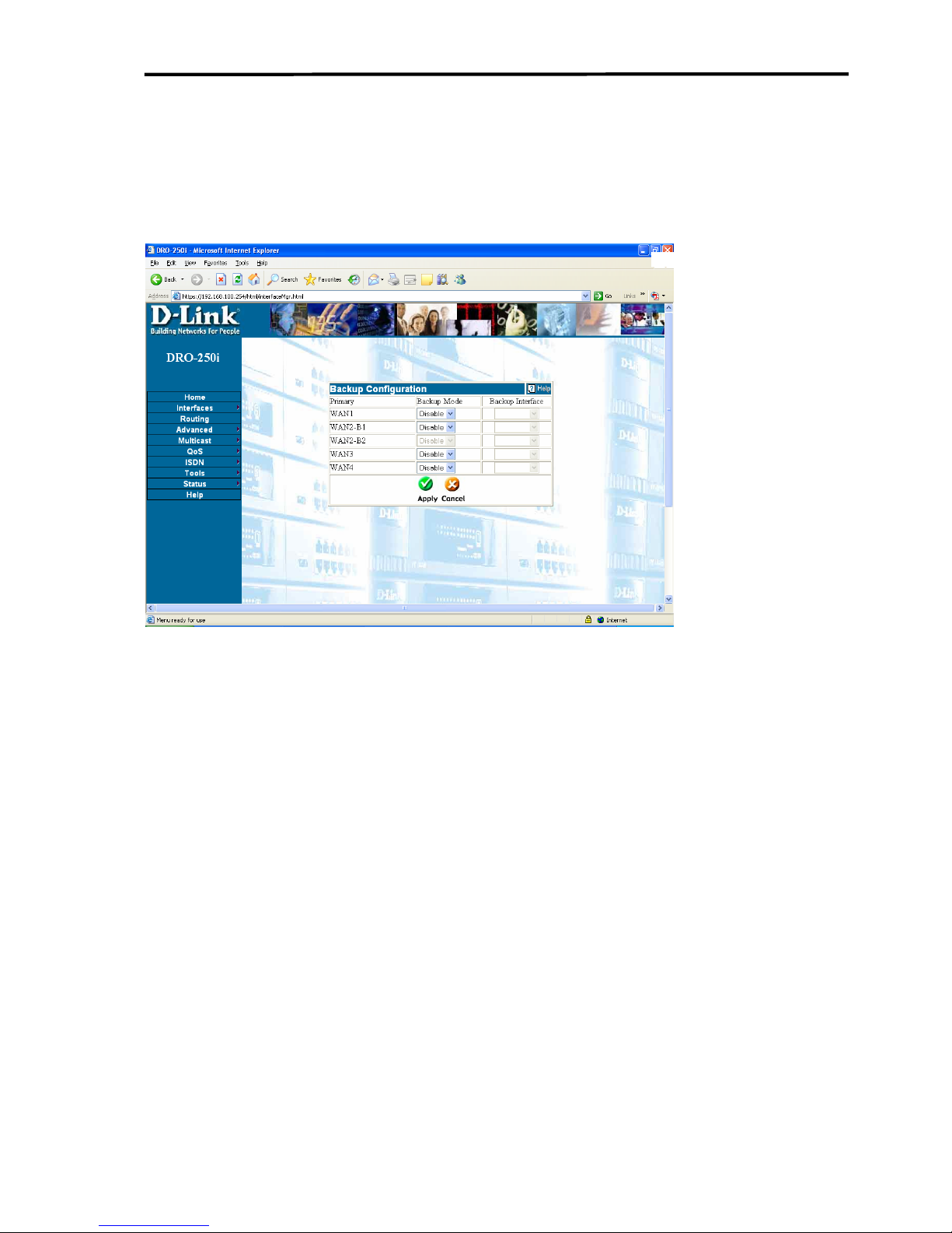
3.2.6 INTERFACES-BACKUP CONFIG
Click on Interface > Backup Config to get the Backup config web page
as shown below:
This Web Page is used to configure primary and backup relation between
WAN interfaces of router. Following are the descriptions of the fields on
this page:
Backup Mode:
1. Disable - No backup activity will be done for this interface.
2. Auto - If the primary interface goes down, the backup interface
configured for this will be connected automatically. In addition to this, all
features pertaining to the backup interface will be applied automatically.
3. Manual - If primary interface goes down, backup interface won't be
connected automatically. If user connects the backup manually all the
features like NAT, Virtual Server and Static routes pertaining to this
backup interface will be automatically configured.
Backup Interface: This interface will be configured as backup interface
for the primary.
DRO-250i User Manual
46
Page 48

Introduction to DRO-250i
There exists a one-to-one relationship between the primary and backup
interface. Following rules apply for backup configuration:
1. Cannot configure a single interface to act as backup for two or more primary
interfaces.
2. If an interface is configured as a backup interface it cannot be made a primary
interface.
3. When auto backup is selected all configurations other than Virtual Server and
VPN made for a backup interface will be applied automatically, like the connection
type for the WAN interface, Static Routes configured on this interface, NAT
configured on this interface, etc.
4. An interface cannot be connected manually if it is made a backup interface in
auto mode.
5. An interface cannot be connected manually if it is made a backup interface in
manual mode and its primary interface is connected.
DRO-250i User Manual
47
Page 49
Configuring DRO-250i
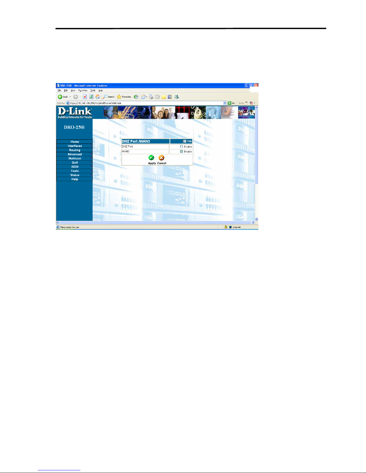
3.2.7 INTERFACES-DMZ/WAN3
Click on Interface > DMZ/WAN3 to get the web page as shown below:
DRO-250i users can use the same physical port as DMZ or Ethernet
WAN, called WAN3. User can check the option if he/she wants. After
checking the proper option i.e. DMZ or Ethernet WAN, checked physical
port will behave in that manner.
For example, if currently the port is working as DMZ port, and then user
can check the option of Ethernet WAN and then click on Apply. After
which the device and the port will start behaving as Ethernet WAN. It
works vice versa too.
DRO-250i User Manual
48
Page 50
Introduction to DRO-250i
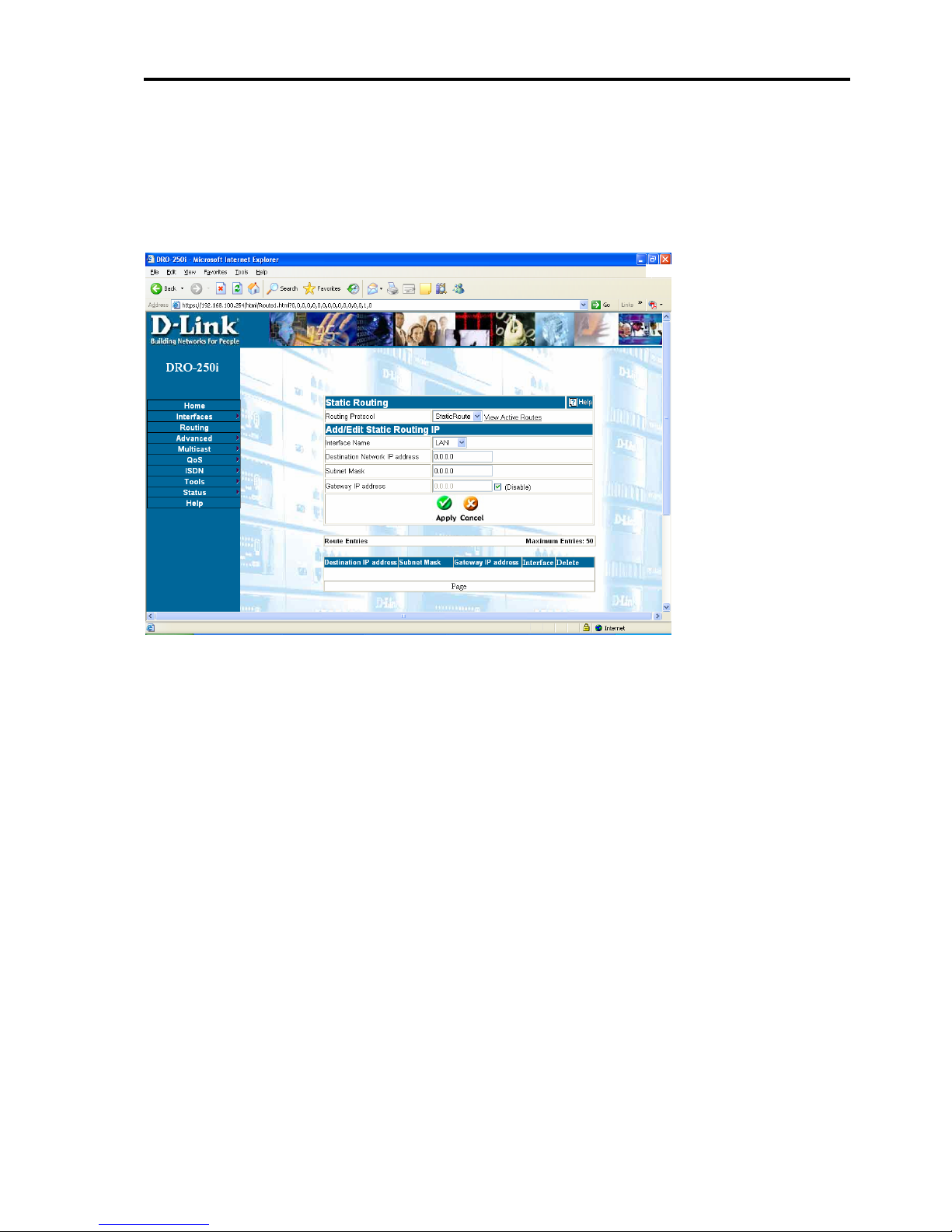
3.3 Routing
Click on Routing to get the web page as shown below:
Static Route Settings
Static Route Web Page allows the user to add and delete static routes.
View link: by clicking on this link the user can see all the active routes.
Interface Name: Select the interface name e.g. LAN, WAN1 and WAN2
etc. Interface WAN2 (ISDN) can be configured as a single 64kbps, single
128kbps or 2-64kbps channels. In case of a single channel user can add
routes for B1 only. In case of two channels, routes can be configured for
both B1 and B2.
Destination Network IP address: Destination Network IP address for
which route is to be added.
Subnet Mask: Specify the subnet mask for the destination Network IP
address.
Gateway IP address: The Gateway IP address for the route. This is an
optional field
DRO-250i User Manual
49
Page 51
Configuring DRO-250i
Route Entries: This table will show all the routes user configures for all
the interfaces. The colour scheme will tell which route is active and which
is not.
1-Entries with yellow colour are active entries (the interface for which the
user has entered these entries is up).
2-Entries with grey colour are inactive entries (the interface for which the
user has entered these entries is down).
RIP Settings
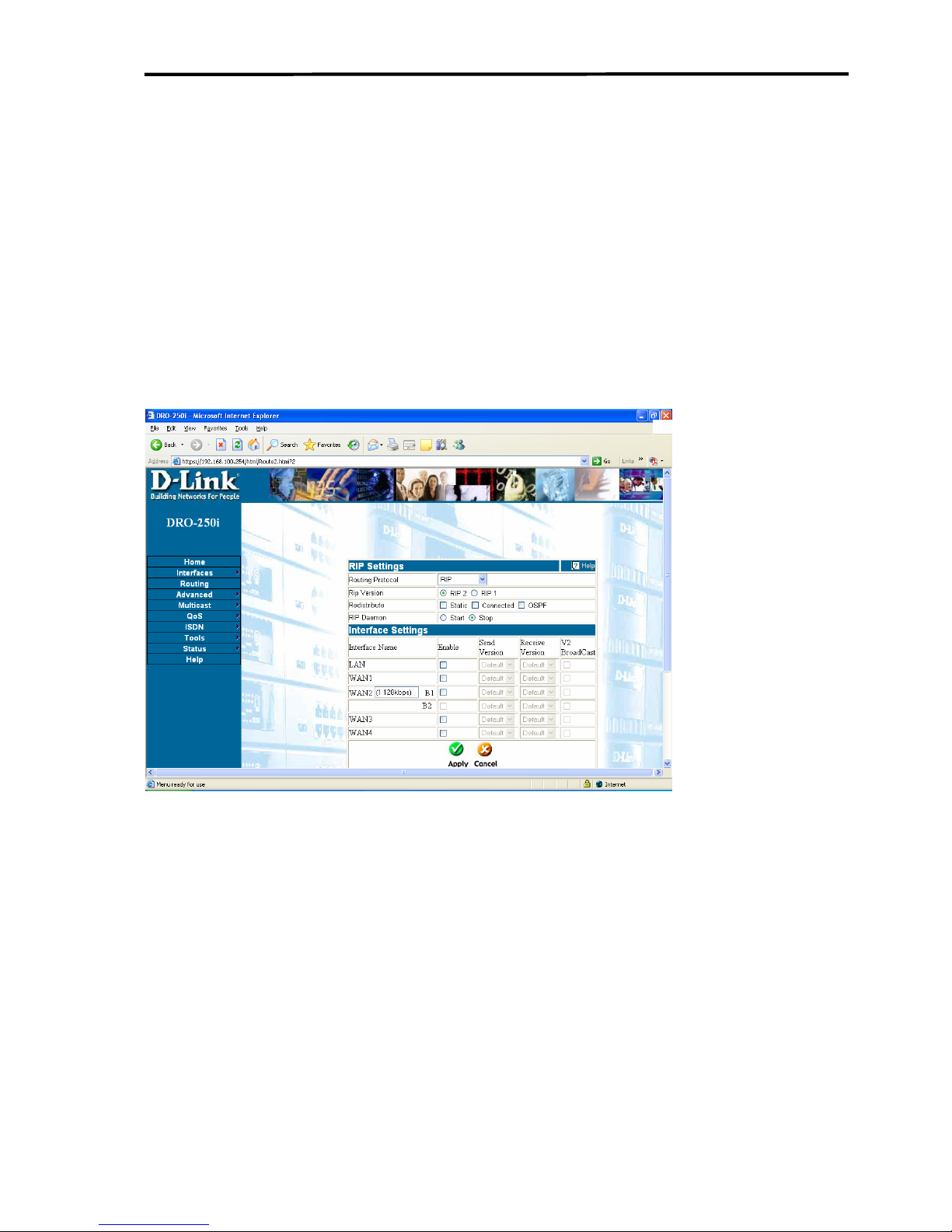
RIP page allows user to configure the RIP Routing Protocol. In the web
page, user can also customize RIP settings for every interface.
RIP Version:
RIP version can be either 1 or 2.
Redistribute:
Static, Connected and OSPF routes can be redistributed into the RIP table.
RIP Daemon:
Start or Stop the RIP Daemon.
DRO-250i User Manual
50
Page 52

Introduction to DRO-250i
Interface Settings:
Configure interface specific RIP settings.
Interface Name:
Name of the interface for which RIP can be configured. Interface
WAN2(ISDN) can be configured as a single 64kbps, single 128kbps or
two 64kbps channels. In case of a single channel, only B1 will be
configurable by the user. In case of two channels, both B1 and B2 can be
configured.
Enable:
Enable or disable RIP on the particular interface.
Send Version:
The interface can use the global default RIP version to send RIP messages,
or be configured to use a specific RIP version.
Receive Version
The interface can use the global default RIP version to receive RIP
messages, or be configured to use a specific RIP version.
DRO-250i User Manual
51
Page 53
Configuring DRO-250i
V2 Broadcast:
When the send RIP version for an interface is set to use RIP 2, user can
choose to broadcast RIP 2 messages instead of the default multicast
behaviour.
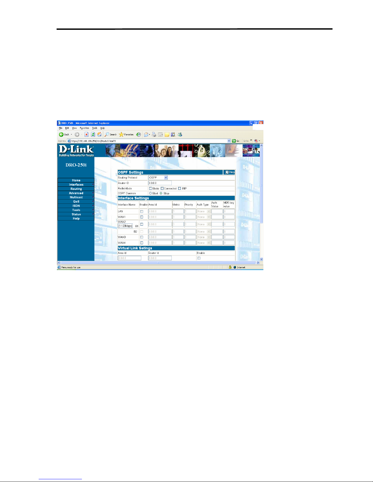
OSPF Settings
OSPF page allows user to configure the OSPFv2 Routing Protocol.
Router Id:
Set the Router ID of the OSPF Router. This is of the 4 octet form as IP
address format.
Redistribute:
Static, Connected and RIP routes can be redistributed into the OSPF table.
OSPF Daemon:
Start or Stop the OSPF Daemon.
Interface Settings:
Configure interface specific OSPF settings.
DRO-250i User Manual
52
Page 54

Introduction to DRO-250i
Interface Name:
Name of the interface for which OSPF can be configured. Interface
WAN2(ISDN) can be configured as a single 64kbps, single 128kbps or
two 64kbps channels. In case of a single channel, only B1 will be
configurable by the user. In case of two channels, both B1 and B2 can be
configured.
Enable:
Enable or disable OSPF on the particular interface.
AreaID:
Specify the area to which this interface would belong to. This field takes
the value in the form of an IP address. If you have a decimal format Area
ID, it can be converted to the IP address format. For more details, refer to
the procedure at the end of this section.
Metric Value:
Metric value of the interface (1-65535).
Priority:
The priority of this interface. This field is used in the designated router
election algorithm. Maximum value of priority is 255.
Authentication Type:
Type of Authentication for the packets (Simple or MD5 or none).
Authentication Value:
Authentication string for the Simple or MD5 authentication.
MD5 Key Value:
MD5 checksum Key ID.
Virtual Link Settings:
A maximum of five virtual links can be configured.
Area ID:
The Transit Area that the Virtual Link traverses.
DRO-250i User Manual
53
Page 55

Configuring DRO-250i
Router ID:
The Router ID of the Virtual Neighbor
Area ID Format Conversion:
Follow this procedure to convert Area ID from decimal format to IP
address format.
Step 1: Represent the area id as a hexadecimal number with 8 hex digits.
For example, area id 268 is 0x0000010C in hexadecimal format.
Step 2: The dotted format a.b.c.d can be obtained from this hexadecimal
number. The first two digits represent ‘a’, the next two digits ‘b’, next two
digits ‘c’ and the last two digits represent ‘d’.
For example in 0x0000010C,
a = 00 (i.e 0)
b = 00 (i.e 0)
c = 01 (i.e 1)
d = 0C (i.e 12)
Step 3: So Area ID 268 in dotted format (a.b.c.d) is 0.0.1.12
DRO-250i User Manual
54
Page 56
Introduction to DRO-250i
3.4 ADVANCED
3.4.1 ADVANCED- DHCP
3.4.1.1
DHCP - DHCP Servers
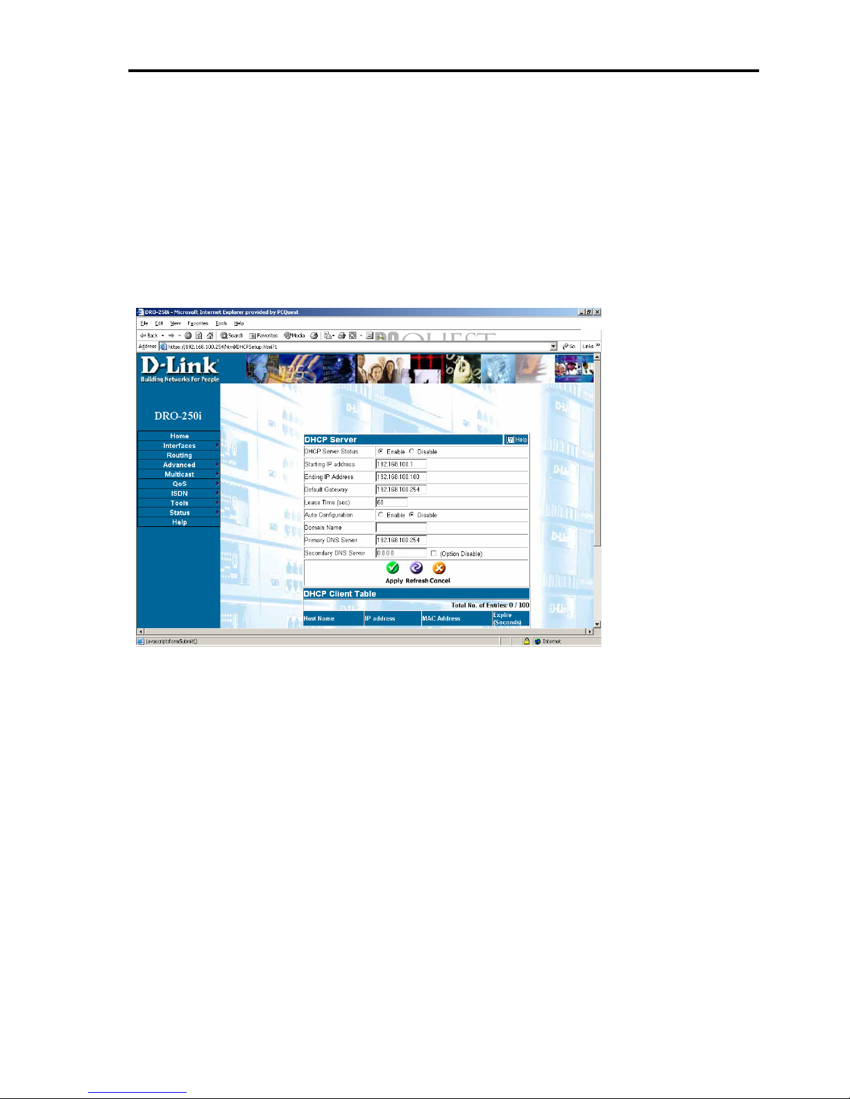
Click on Advanced > DHCP> DHCP Server to get the web page as
shown below:
DHCP (Dynamic Host Configuration Protocol) is a method of
automatically assigning IP addresses, subnet masks, default gateway and
DNS server IP addresses to computers on the LAN side of the Router.
The Router can be a DHCP server for LAN, assigning IP addresses, subnet
mask etc.
DHCP Server Status - This allows user to Enable or Disable the DHCP
Server feature on the Router. The default is Enabled.
Starting IP address - This is the first IP address in a range that the Router
will assign to a computer on network. This IP address cannot be the same
as the IP address assigned to the Router, nor can it be contained in the
range of IP addresses available for the Router to assign. For example, if
the IP address of the Router is 192.168.0.1 the first IP address in the range
DRO-250i User Manual
55
Page 57

Configuring DRO-250i
is 192.168.0.2. IP addresses can range from 0.0.0.0 to 255.255.255.255,
but in the DRO-250i's default IP addressing scheme the range is from
192.168.0.0 to 192.168.0.255. Please note that the addresses ending in 0
and 255 are reserved for other uses, so the effective IP address range is
192.168.0.1 to 192.168.0.254.
Ending IP address - This is the last IP address in a range that the Router
will assign to a computer on user's network. In the above mentioned
example, the range of IP addresses between 192.168.0.2 to 192.168.0.100
gives 99 different IP addresses that the Router can assign to the computers
on user's network.
Lease Time - This is the length of time any computer on user's network
that is assigned network IP address by the Router - through the DHCP
protocol - can keep its network settings. If the lease expires while a
computer is logged on, then that computer will request a new set of
network settings. The default is 3600 seconds.
Auto Configuration - This field allows the user to specify whether or not
the Router will assign the following network settings to the computers on
user's network. If Enable Auto Configuration is chosen, then DNS Proxy
is enabled in the Router. The default network settings for the systems in
the user's network will be obtained automatically from ISP by the Router.
If Disable Auto Configuration is chosen by the user, then network settings
entered by the user in the fields will be assigned to computers on user's
network.
Domain Name - The Router can provide a domain name to computers on
the user's network. This domain name suffix can be provided
automatically by user's ISP or user himself can enter it statically here. This
suffix will then be automatically added to URL requests for access to
ISP’s servers. This setting is optional.
Primary DNS Server - This is the IP address of a server on the Internet
that provides the service of changing text URLs into IP address for sites
on the Internet. The IP address of this server is provided by the ISP.
Secondary DNS Server - This is the IP address of a secondary DNS
server, to be used in case of a problem with the primary DNS server. A
DRO-250i User Manual
56
Page 58

Introduction to DRO-250i
secondary DNS server IP address is optional. Check disables checkbox to
disable secondary DNS.
DHCP client table shows the client computers to which the IP addresses
have been assigned by DHCP. The DHCP Client Table will show the Host
Name, IP address, MAC Address, and Expire Time of the DHCP lease for
each client computer.
DRO-250i User Manual
57
Page 59
Configuring DRO-250i
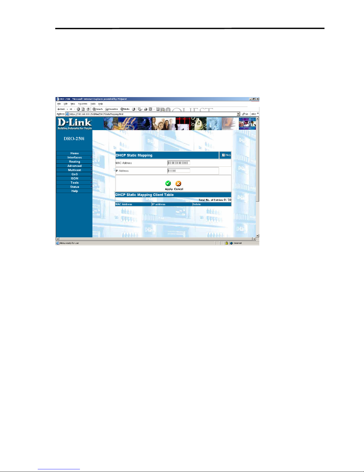
3.4.1.2 DHCP -DHCP Reservation
Click on Advanced > DHCP >DHCP Reservation to get the web page
as shown below:
DHCP Reservation is a method of assigning the static IP address to a
defined MAC Address. System administrator can use this feature to
configure the static IP address for some of the systems in the LAN. These
IP address, however will fall in the DHCP server configured IP address
range
DRO-250i User Manual
58
Page 60
Introduction to DRO-250i
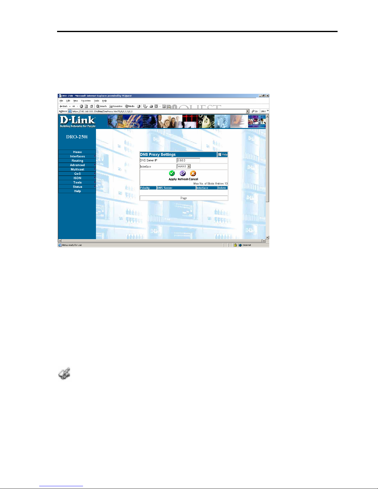
3.4.2 ADVANCED-DNS Proxy
Click on Advanced > DNS Proxy to get the web page as shown below:
DNS Server IP : This is the IP address of the DNS Server provided by the
ISP .
Interface: This is the Interface name corresponding to the DNS Server IP
entered . If Two or more interfaces have the same DNS Server , select the
interface type as DEFAULT . The interface with DEFAULT type will
have the highest priority.
All the static DNS entries are displayed in gray color and all the dynamic
DNS entries are displayed in yellow color.
In the DHCP Server Setting page Enable the Auto Configuration , for the
computers on the user's network to use the DNS Proxy .
DRO-250i User Manual
59
Page 61
Configuring DRO-250i
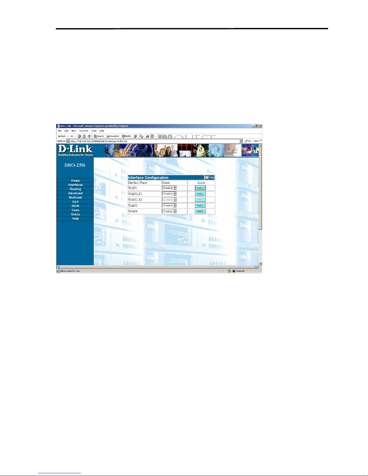
3.4.3 ADVANCED-NAT
3.4.3.1 NAT - Interface Configuration
Click on Advanced > NAT> Interface Configuration to get the web
page as shown below:
NAT can be Enabled/Disabled on the specific interface on this page.
Enable the interface on which the NAT is to be applied and then click
Apply. To configure the NAT, visit NAT configuration Page.
DRO-250i User Manual
60
Page 62
Introduction to DRO-250i
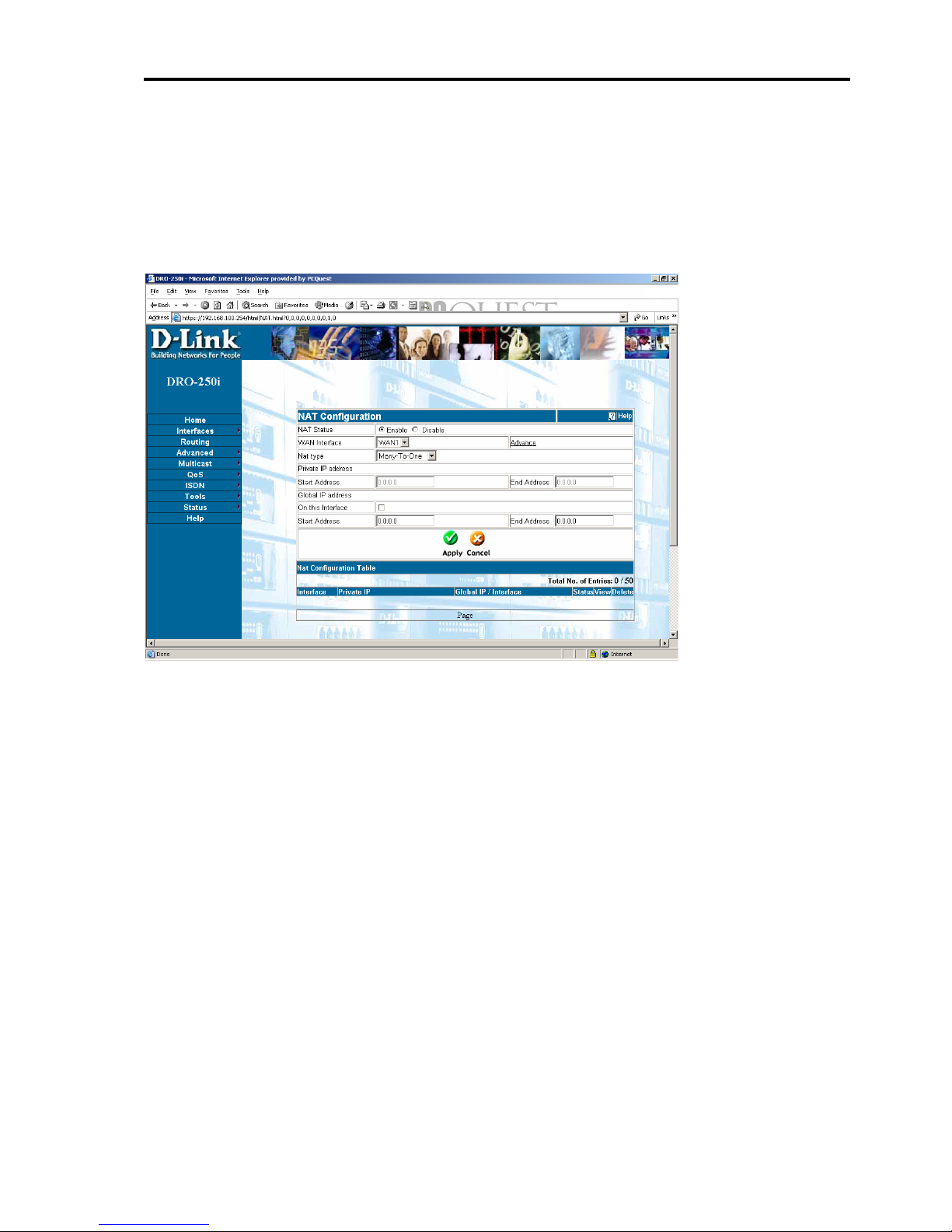
3.4.3.2 NAT - NAT Configuration
Click on Advanced > NAT> NAT Configuration to get the web page as
shown below:
NAT - Enable or Disable the NAT Configuration for the WAN Interface
selected. This field only Enable/Disable the particular NAT
Configuration entry made. To Enable/Disable NAT on the specific
Interface, make the configuration in the Interface Configuration webPage.
WAN Interface- Select the WAN Interface from the drop-down menu on
which the NAT Configuration entry has to be made.
NAT Type - Select the type of NAT to be applied on the interface from
the drop-down menu. The types that can be configured are:
• Many-To-One: Any IP from Private network passing through the
NAT enabled interface are mapped to the single Global IP specified.
Instead of specifying the global IP, Interface checkbox can be
selected. This makes the Interface IP to be the Global IP to which all
DRO-250i User Manual
61
Page 63

Configuring DRO-250i
the Private IP is mapped. User need not specify the Private IP. The
Global Start Address and Global End IP Address need to be same.
• Many-To-Many: Any Private IP through the NAT enabled
interface are mapped to the range of Global IPs specified. User need
not specify the Private IP. User can specify a range of IPs by giving
the starting value of the range in Global Start IP and ending IP in
Global End IP address.
• One-To-One.: One IP in private network is mapped to the
corresponding global IP specified. IP range can also be configured
by giving the starting and ending Private and Global IPs. The Private
IP range and the Global IP range need to be same for one-to-one
mapping.
•
Private IP - Specify the start IP and the end IP to configure a range of
IPs. In case of single IP, please enter the same IP in both the fields.
Global IP - Specify the start IP and the end IP to configure a range of
IPs. In case of single IP, please enter the same IP in both the fields.
A table is displayed showing the NAT configurations made by the user.
The entry can be enabled or disabled by clicking the view button. For Eg,
To disable an NAT Configuration entry already made, click on the view
and make it disable and Apply again. Click on delete button to delete the
NAT configuration entry. This will remove the entry from table.
Conditions -
• User cannot make 2 Many-To-One entries for a particular interface.
• User cannot make a Many-To-One entry when Many-To-Many entry
exist for any interface.
• The IP range of Many-To-One should not overlap with the
existing One-To-One entry for any interface.
• User cannot make Many-To-Many entry when Many-To-One entry
exist for that interface.
DRO-250i User Manual
62
Page 64
Introduction to DRO-250i
• The IP Range of Many-To-Many entry should not overlap with the
existing Many-To-Many or One-To-One entry for any particular
interface.
• One-To-One can co-exist with Many-To-One or Many-To-Many
entry.
• One-To-One IP range should not overlap with the existing Many-To-
Many or Many-to-One entry for any given interface
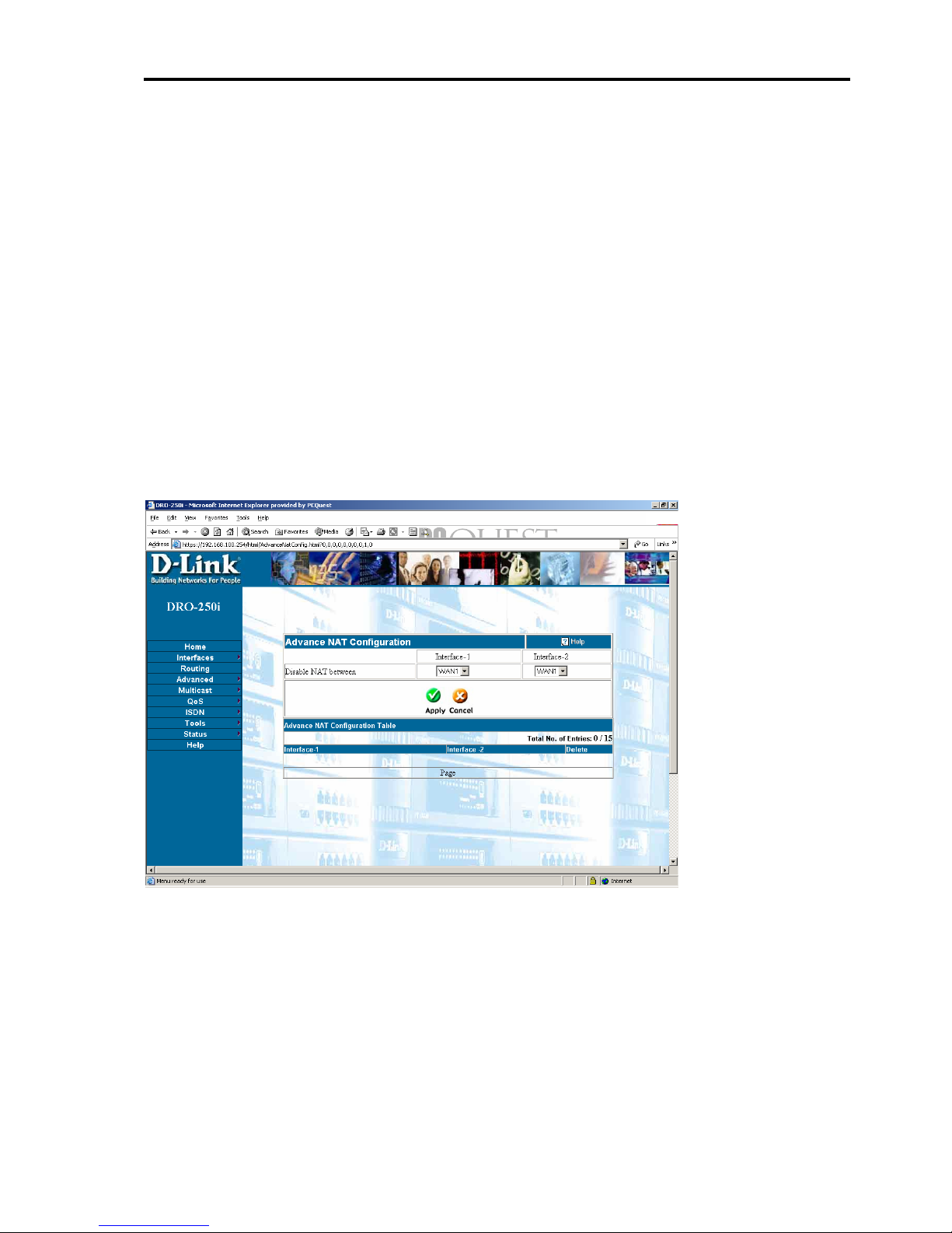
3.4.4 NAT - Advanced NAT
Click on Advanced > NAT> Advanced NAT to get the screen as shown
below:
The NAT can be disabled between 2 interfaces. If Advanced NAT is
applied for Interface 1 and Interface 2, then sessions passing through the
Interface2 and generated from interface1 are not NATed. To remove the
exception entry made, click delete.
DRO-250i User Manual
63
Page 65
Configuring DRO-250i
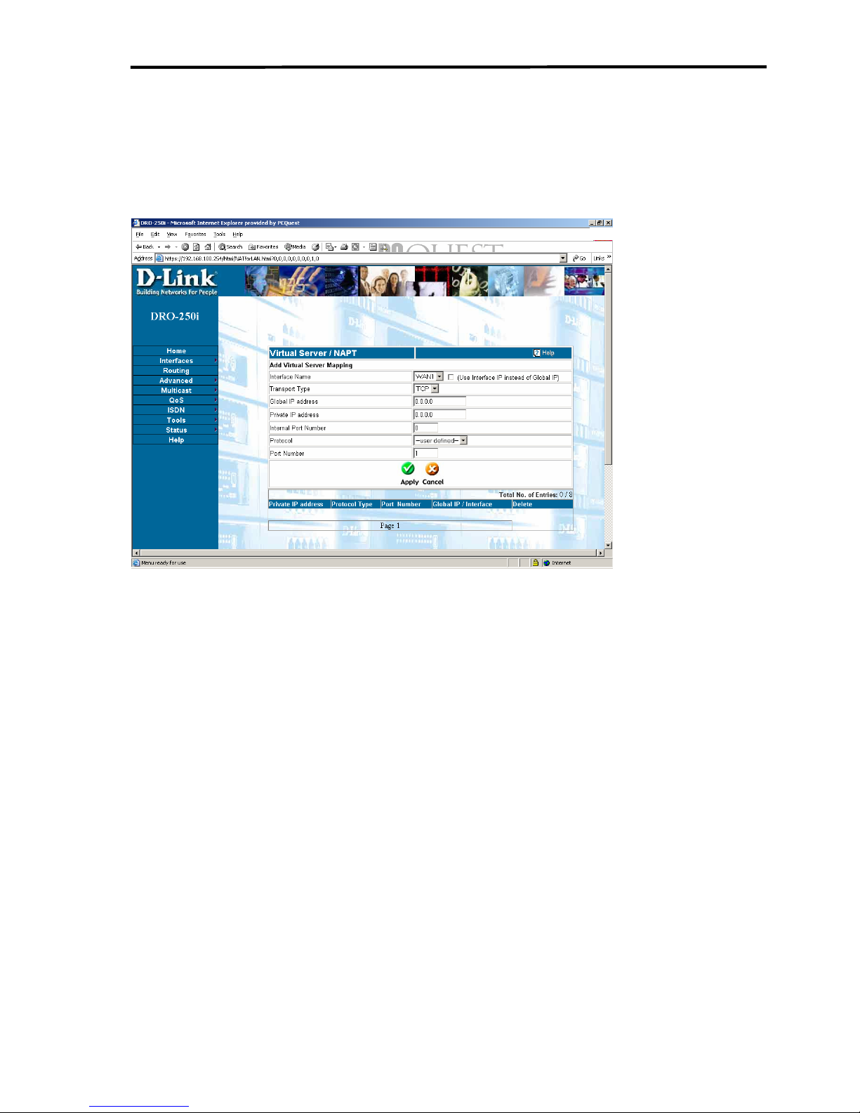
3.4.5 ADVANCED - Virtual Server
Click on Advanced > Virtual Server to get the web page as shown
below:
Virtual Servers allow remote users to access services on LAN such as FTP
for file transfers or STMP and POP3 for e-mail. The user configures
global IP address that the remote client uses, TCP or UDP protocol and
port number. The virtual server redirects these requests from remote
clients to the server running the specified service on LAN by translating
the global IP to the user's Private IP address. Remember that the Global IP
address must be within the range specified on the NAT Settings page, and
that the Private IP address must be within the range specified for LAN.
Interface Name: This is the WAN interface which will be used for the
servers.
Private IP - This is the IP address of the server on LAN that will provide
the service to remote users.
Transport Type - User can select the transport protocol (TCP or UDP)
that the application on the virtual server will use for its connections. The
DRO-250i User Manual
64
Page 66

Introduction to DRO-250i
choice of this protocol is dependent on the application that is providing the
service.
Protocol - User can select from a list of commonly used protocols from
this drop-down menu. This is the equivalent of entering the correct
Transport Type (TCP or UDP) and the correct port number corresponding
to a given protocol. The only difference is that the protocol is identified by
name. For example, the Simple Mail Transfer Protocol (SMTP in the
drop-down menu) is used to send/receive e-mail. It uses the TCP transport
protocol and port number 25. This information will be entered for user, if
user selects SMTP from the Protocol drop-down menu.
Port Number - Select the TCP or UDP port number which the application
will use for its connections. The choice of this protocol is dependent on
the application that is providing the service. If user does not know which
protocol to choose, then he/she can check application’s documentation.
DRO-250i User Manual
65
Page 67
Configuring DRO-250i
3.4.6 ADVANCED –FIREWALL
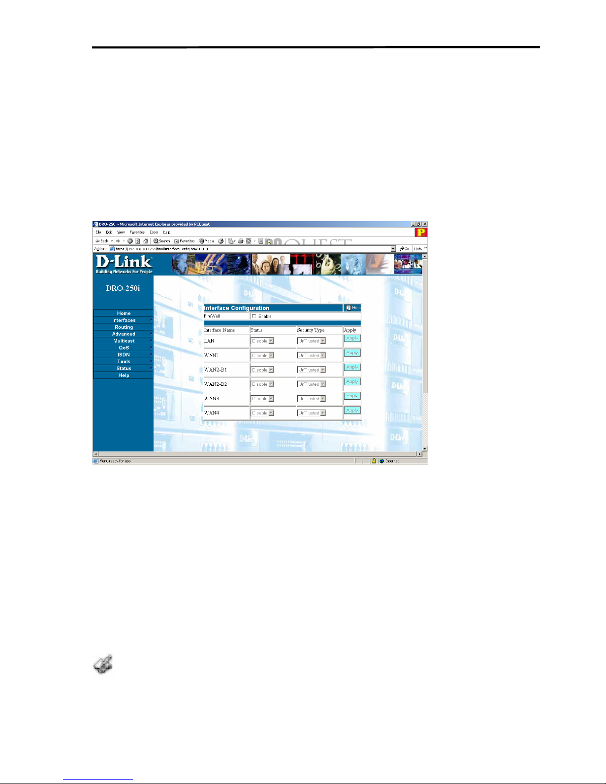
3.4.6.1 Firewall-Interface Configuration
Click Advanced > Firewall > Interface Configuration get the web page
as shown below:
Firewall Enabled: Firewall will be active only when flag is selected;
when this flag is not selected firewall is disabled on all Interfaces.
Status: Firewall can be enabled/ disabled on a particular Interface with
this field.
Security Type: Interfaces can be set to either trusted or un-Trusted type
on this field. If the security type is set to Trusted then Outbound Policies
will be applied on that interface, if the security type is set to Un-Trusted
then Inbound Policies will be applied on that interface.
If more than one interface is of same security type then Policy database for
them is same i.e. if WAN1 and WAN3 are configured as Un-Trusted then both of
them will share a common Inbound Policies database.
DRO-250i User Manual
66
Page 68

Introduction to DRO-250i
If user configures LAN as Un-trusted, then user needs to configure
Remote Access for getting the web-configuration. So before configuring
LAN as un-trusted, user should enter the IP of the LAN PC (which is
configuring the DRO-250i) in the Remote access configuration web-page.
DRO-250i User Manual
67
Page 69
Configuring DRO-250i
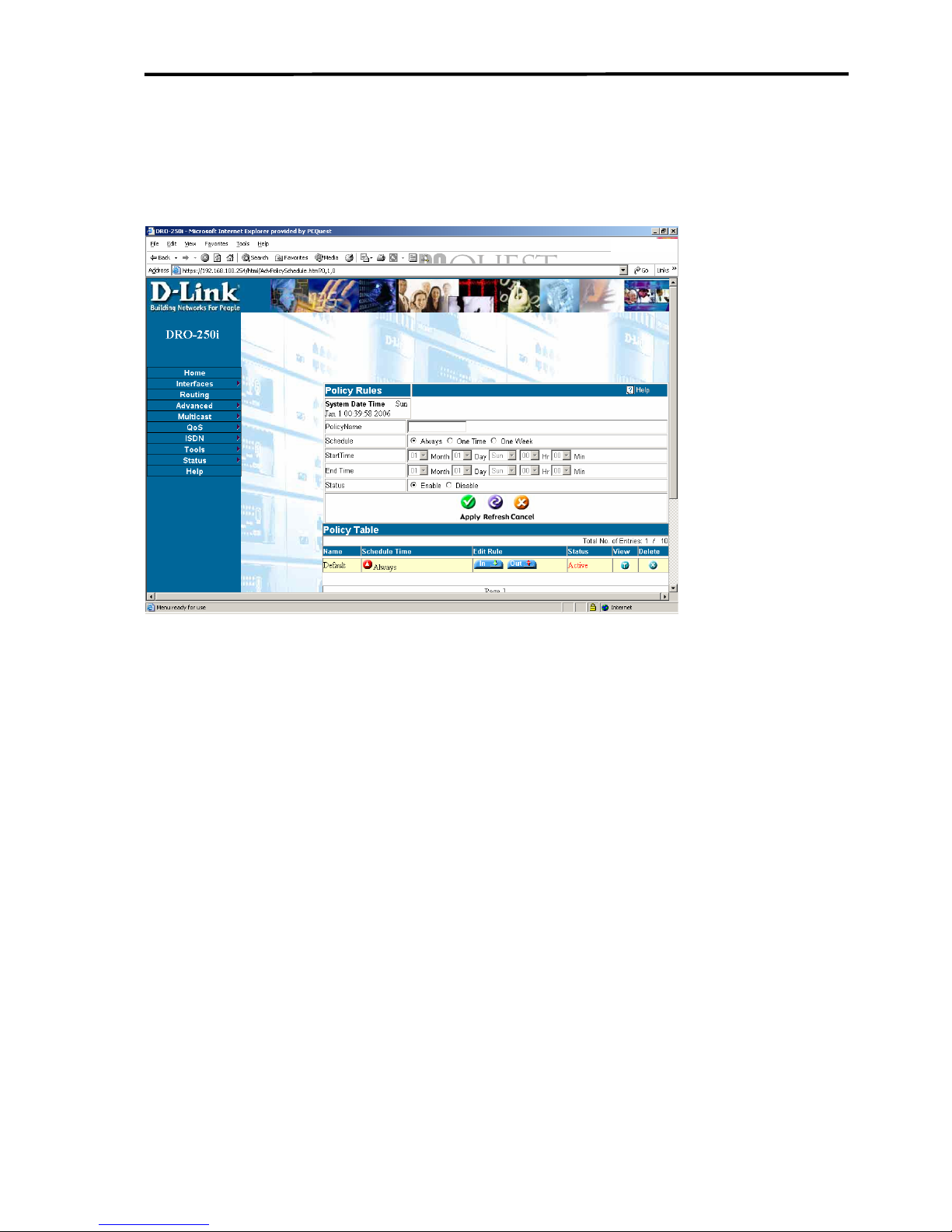
3.4.6.2 Firewall- POLICY
Click Advanced > Firewall > Policy to get the web page as shown below:
Policy (Firewall) Schedule
DRO-250i allows the user to configure three types of policies which are
Always, One-Time and one-week. “Always” Policy is used when user
wants the policy to be active all the time. If user wants to activate some
firewall policy, then enter a “one-time” policy with the required time and
that policy will be activated whenever that time comes. “One-week”
policy is also used for the same purpose. Please remember that if there is
any “Always” policy above the “One-time” or “One-week”, then
“Always” policy will be active. So please keep “One-time” and “Oneweek” policies on the top of the “Always” policies so that they can
become active when their time arrives.
User can disable any particular policy if it is required to activate any other
policy. For example, if there are two policies One-time and always, and
currently if “One-time” policy is active. If user wants to make “Always”
policy as active, then select the “One-time” policy and disable it.
DRO-250i User Manual
68
Page 70

Introduction to DRO-250i
Automatically “Always” policy will become active. The same thing can be
used with the “One-week” policy also.
Policy (Firewall) Rules
The Router allows you to specify a range of IP addresses, MAC addresses,
and Domain names for connections between computers on the WAN and
computers on user's LAN that will be controlled. The default firewall rules
of Router are as following: allow all network traffics going to WAN or
network traffics coming from WAN to access virtual server, deny network
traffic coming from WAN to access web management of Router.
Port Filter Status - Port Filter Policy used to allow or deny network
packets both coming from and going to the WAN is based on the
Transport type and port number. When Enable is selected, the packet in
the port filter list will be allowed to pass through the firewall. For
outbound packet, it will also go through IP Range Filter, Domain Filter,
and MAC Filter check. When Disable is selected, all packets will pass
through the firewall.
IP Range Filter Status - When Enable is selected, the IP Filter will be
applied to packets going to the WAN. The packet in the IP filter list will
be dropped. When Disable is selected, the packet in the IP filter list will
not be dropped.
MAC Filter Status - When Enable is selected, the MAC Filter will be
applied to packets going to the WAN. The packet in the MAC filter list
will be dropped. When Disable is selected, the packet in the MAC filter
List will not be dropped .
Domain Filter Status - When Enable is selected, the Domain Filter will
be applied to packets going to the WAN. The packet in the Domain filter
list will be dropped. When Disable is selected, the packet in the Domain
filter list will not be dropped.
Port Filter -The Router allows you to specify a range of TCP or UDP
ports for connections between computers on the WAN and computers on
your LAN that will be controlled. These TCP or UDP ports are entered on
DRO-250i User Manual
69
Page 71

Configuring DRO-250i
page
Transport Type - This drop-down menu allows you to specify the
transport protocol that will be filtered by the Router. You can choose from
the TCP, UDP, ICMP, IGMP, GRE, AH, ESP, and IPCOMP protocols.
Protocol - You can select from a list of commonly used protocols from
this drop-down menu. This is the equivalent of entering the correct
Transport Type and the correct port number corresponding to a given
protocol. The difference here is that the protocol is identified by name. For
example, the Simple Mail Transfer Protocol (smtp in the drop-down
menu) is used to send and receive e-mail. It uses the TCP transport
protocol and port number 25. This information will be entered for you, if
you select smtp from the Protocol drop-down menu.
Port Range - You can enter a range of port numbers for which the current
policy rules will be applied. If you have only one port number to enter,
enter it in both fields.
Direction - This allows you to specify the source of network traffic for
which the current policy entry will be applied - from the Internet
(Inbound), or from your LAN (Outbound).
IP Range Filter - The IP Range Filter page allows you to deny access to
the WAN (Internet) from specific computers on your LAN, by specifying
the computer's IP address on the WAN (Internet).
Source IP address From - This allows you to specify the first in a range
of IP addresses that the IP filter policy will be applied to. If you have only
one IP address that you want to filter, enter this address in both the From
and To fields.
Source IP address To - This allows you to specify the last in a range of
IP addresses that the IP filter policy will be applied to. If you have only
one IP address that you want to filter, enter this address in both the From
and To fields.
DRO-250i User Manual
70
Page 72
Introduction to DRO-250i
MAC Filter
These settings are used to deny LAN computers from accessing the
Internet based on their MAC address
Domain Filter
These settings are used to deny LAN computers from accessing the
Internet based on URL Domain Name String
3.4.6.3
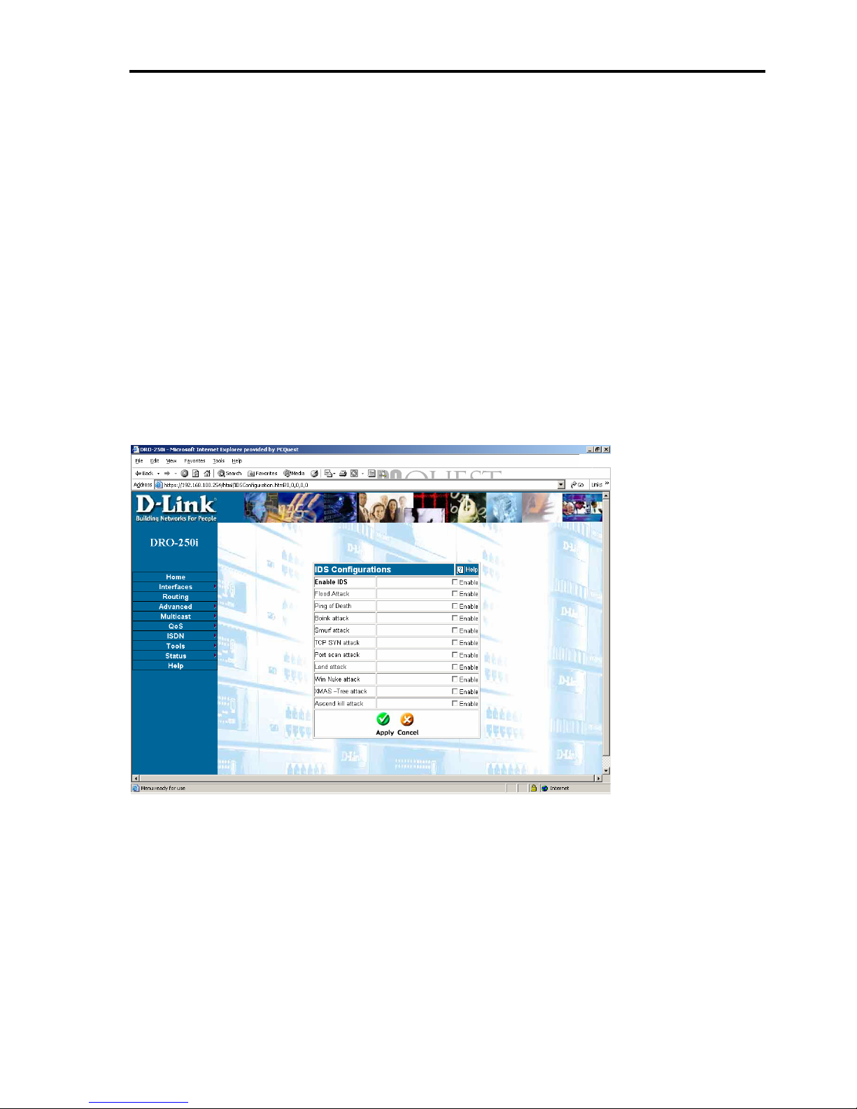
FIREWALL – IDS Configuration
Click Advanced > Firewall > IDS to get the screen as shown below:
IDS Configuration
IDS - Intrusion Detection System detects few of the known Attacks. The
attacks detected by the IDS system can be configured in the IDS
Configuration webpage. The user can enable detection of the attacks by
checking the checkboxes. The attacks are classified into categories based
on type of attack.
DRO-250i User Manual
71
Page 73

Configuring DRO-250i
IDS Configuration - To Enable or Disable IDS
Flood Attack - SYN flood attack, ICMP flood attack, ICMP Echo storm
attack are detected under this category. In these attacks, packets are
flooded continuously on the target machine.
Ping of Death - A form of DoS (denial of service) attack consisting of a
flood of ping requests designed to disrupt the normal activity of a system.
Boink Attack - It involves the perpetrator sending corrupt UDP packets to
host.
Smurf Attack - The "smurf" attack, named after its exploit program, is
the most recent in the category of network-level attacks against hosts.
TCP SYN Attack - TCP SYN/ACK attack, FIN attack, RESET attack are
detected under this category. These attacks exploit the TCP 3 way
handshake.
Port scan Attack - Netbus scan, Back orifice scan, Echo chargen scan,
UDP echo scan, Chargen scan, IMAP scan are detected under this
category. Particular ports are scanned under this attack.
Land Attack - The Land attack involves the perpetrator sending spoofed
packet(s) with the SYN flag set to the victim's machine on any open port
that is listening. If the packet(s) contain the same destination and source IP
address as the host, the victim's machine could hang or reboot.
Winnuke Attack - Denial of service attack to any windows 95/NT/3.x
user by sending OOB data to an established connection on port 139
[NetBIOS].
XMAS-Tree Attack - DoS technique that sets all TCP header flags to on
in an attempt to gain information regarding a network.
DRO-250i User Manual
72
Page 74

Introduction to DRO-250i
Ascend kill Attack - It was possible to make the remote Ascend router
reboot by sending it a UDP packet containing special data on port
9(discard).
The Attacks are logged in the Intrusion Log webpage. The IPs of the
attacker are blacklisted for prevention of further Attacks from the same IP.
Check all the checkboxes for effective Intrusion Detection System.
DRO-250i User Manual
73
Page 75
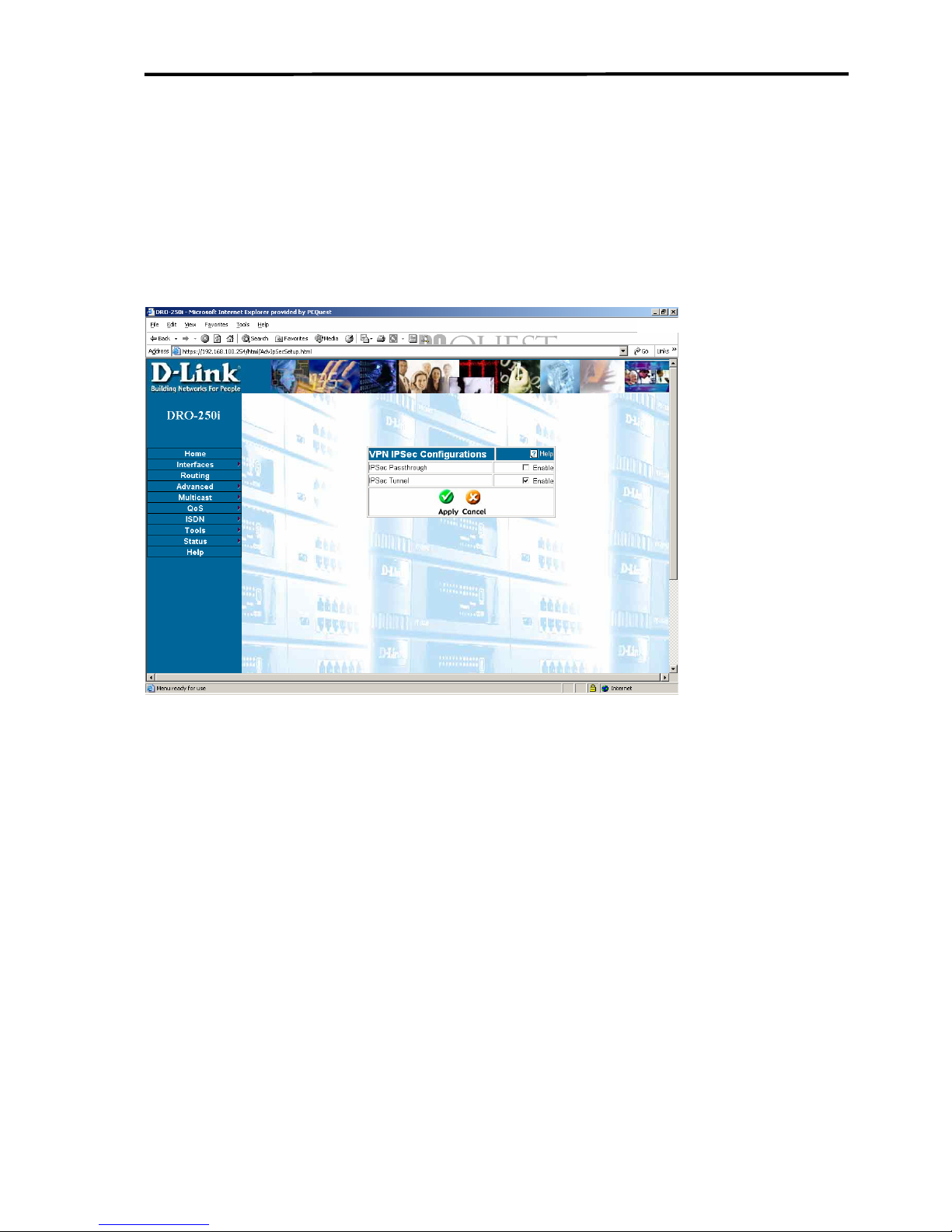
Configuring DRO-250i
3.4.7 ADVANCED -VPN
3.4.7.1 VPN – VPN-IPSEC
Click on Advanced > VPN >VPN- IPSec to get the web page as shown
below:
IPSec (Internet Protocol Security) is a group of protocols designed to
allow flexible, secure and interoperable communication over the Internet.
IPSec is used to establish an encrypted - and therefore, secure - connection
between two points on a network. IPSec provides access control,
connectionless data integrity, data origin authentication, protection against
replay attacks and confidentiality for each IPSec packet. This is achieved
by using headers and trailers on each packet, which provide core pieces of
information pertaining to authentication, data integrity, and
confidentiality. The AH (Authentication Header) addresses data origin
authentication, data integrity, and replay protection. The ESP
(Encapsulating Security Payload) header addresses the same features and
also includes data confidentiality or encryption capabilities. By default,
IPSec uses the AH as a minimum level for its capabilities. If data
confidentiality is desired, the AH is replaced with an ESP header for the
DRO-250i User Manual
74
Page 76

Introduction to DRO-250i
encryption feature and the authentication and data integrity components
that the AH offer as well.
IPSec Passthrough - Click Enable to allow IPSec packets to pass through
the router to the destination computer on your LAN. When IPSec Passthrough is enabled, the Router will allow IPSec packets to reach their
destination computer on your LAN.
IPSec Status - Click Enable to make the IPSec settings active.
DRO-250i User Manual
75
Page 77
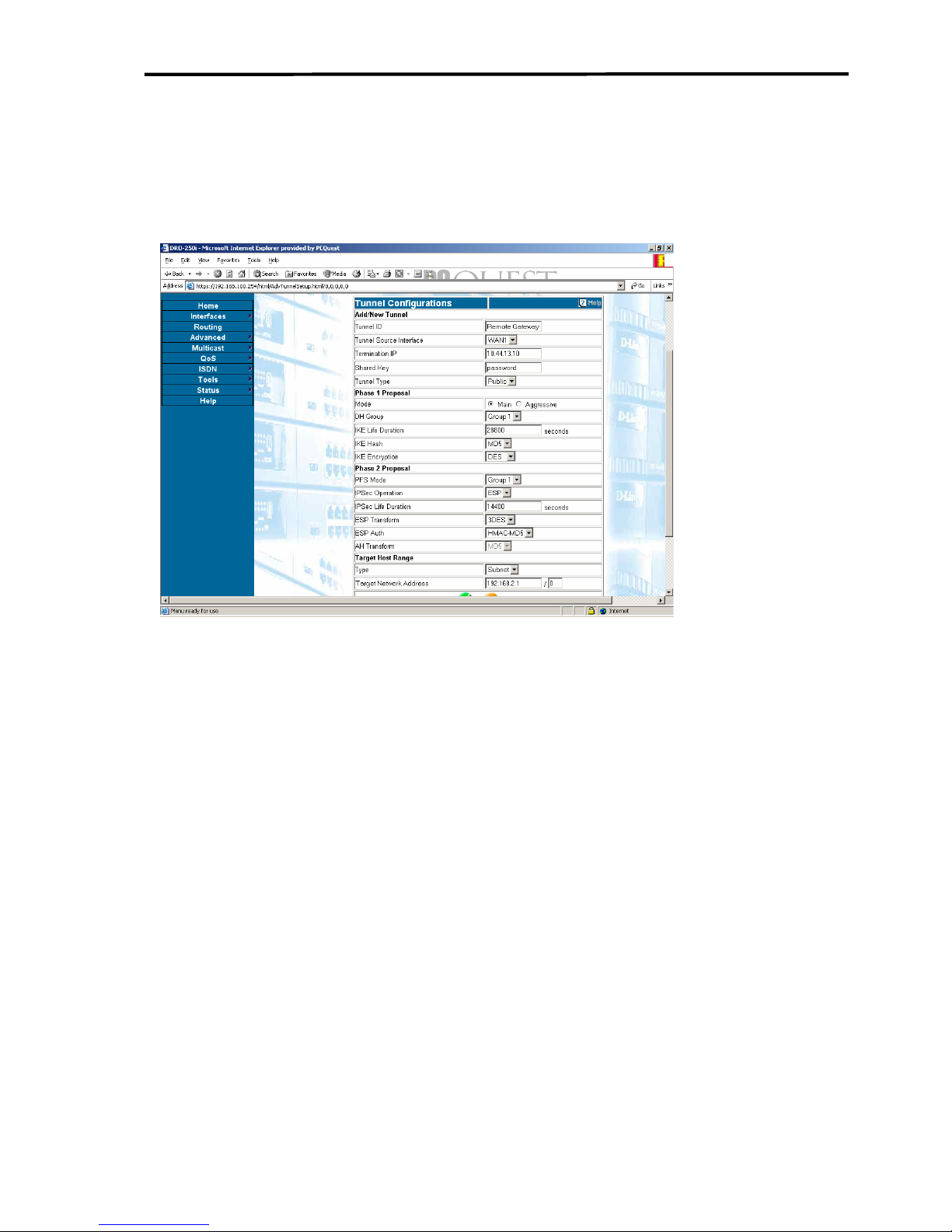
Configuring DRO-250i
3.4.7.2 VPN - Tunnel
Click on Advanced > VPN > Tunnel to get the web page as shown
below:
The IPSEC Tunnel Mode page allows user to setup a secure tunnel
between Router and a remote gateway.
Add/New Tunnel
Tunnel ID - An alphanumeric string that identifies the remote tunnel. A
string of up to 63 characters can be entered. The Tunnel ID is sometimes
called the Negotiation ID of the remote gateway.
Tunnel Source Interface - The WAN interface name which serves as the
tunnel source endpoint. Interface WAN2 (ISDN) can be configured as a
single 64/128kbps or 2-64kbps channels. When two 64kbps channels have
been configured, either of the channels (B1 or B2) can be selected as the
tunnel source.
Termination IP - The IP address of the remote gateway.
Shared Key - The encryption key that should be entered exactly the same
way on both endpoints in order to establish Phase I negotiation.
DRO-250i User Manual
76
Page 78

Introduction to DRO-250i
Tunnel Type - This drop-down menu allows user to select the type of
VPN Tunnel user wants to configure. User can choose between Public,
Private, and Manual. At the time of writing of this manual, only Public
IPSec VPN tunnels were supported.
Phase 1 Proposal
Mode - User can select between Main and Aggressive modes for the
Phase 1 negotiation to establish a VPN IPSec tunnel. In the Main mode,
communication between the two endpoints of an IPSec VPN tunnel are
encrypted. In Aggressive mode, there is no encryption in the Phase 1
negotiation.
DH Group - The DH algorithm allows the Router to generate secret keys
for encryption for the Phase 1 negotiation. Group 1 generates a 768-bit
key and Group 2 generates a 1024-bit key. The same DH Group must be
used on both ends of an IPSec VPN tunnel.
IKE Life Duration - This is the life duration of phase 1 key (in seconds).
When it is expired, the two peer site should
trigger phase 1 negotiation again to set up a new phase 1 key , phase 2
negotiation also will be triggered.
IKE Hash - This drop-down menu allows user to select the algorithm that
will be used to ensure that the messages exchanged between the two IPSec
VPN tunnel endpoints have been received exactly as it was sent. In other
words, a Hash algorithm is used to generate a binary number by a
mathematical operation using the entire message. The resulting number is
called a message digest. The very same mathematical operation is
performed when the message is received, and if there has been any change
in the message in transit, the resulting message digest number will be
different and the message will be rejected. User can choose between MD5
- a 128-bit message digest, and SHA - which generates a 160-bit message
digest. User must have exactly the same IKE Hash algorithm on both ends
of a VPN tunnel.
IKE Encryption - This drop-down menu allows user to select the
encryption algorithm that will be used to encrypt the messages passed
between the VPN tunnel endpoints during the Phase 1 negotiation. User
DRO-250i User Manual
77
Page 79

Configuring DRO-250i
can choose between DES and 3DES encryption methods. The key length
for the 3DES algorithm is three times as long as the DES key, and is
therefore more likely to be secure. User must choose exactly the same IKE
encryption algorithm on both ends of a VPN tunnel.
Phase 2 Proposal
PFS Mode - This drop-down menu allows user to specify the mode that
will be used for IPSec Perfect Forward Security (PFS). The choices are
Disable, Group 1, and Group 2. Group 1 uses 768-bit encryption, , Group
2 uses 1024-bit encryption and Disable disables the PFS mode. User must
use exactly the same PFS encryption mode on both ends of the VPN
tunnel.
IPSec Operation - This drop-down menu allows the user to select the
level of encryption that will be applied to packets that are sent between the
two endpoints of a VPN tunnel. ESP - specifies that the entire packet will
be encrypted (by the DES or 3DES algorithm, as selected in ESP tranform
field) and authenticated (by the MD5 or SHA algorithm, as selected in
ESP Authentication field). AH - specifies that only the authentication
algorithm (MD5 or SHA, as selected below) will be used. When AH is
selected, the data portion of packets sent between the two endpoints of a
VPN tunnel will not be encrypted.
IPsec Life Duration - Similar as IKE Life Duration, it's used for life
duration of phase 2 key (in seconds). When it expires the two peer site
should trigger phase 2 negotiation again, to set up a new phase 2 key.
ESP Transform - This drop-down menu allows user to select the
encryption algorithm that will be used when ESP is selected in the IPSec
Operation drop-down menu above. User can choose between Null - no
encryption, DES - using DES encryption, 3DES - using triple DES
encryption and AES - using AES encryption. User must select the exact
same ESP transform (encryption algorithm) on both ends of a VPN tunnel.
ESP Auth - This drop-down menu allows user to select the encryption
algorithm that will be used when ESP is selected in the IPSec Operation
drop-down menu above. User can choose between Null - no authorization,
DRO-250i User Manual
78
Page 80

Introduction to DRO-250i
MD5 - using MD5 message digest authentication, and SHA - using the
SHA authentication method. User must select the exact same ESP
authentication method on both ends of a VPN tunnel.
AH Transform - This drop-down menu allows user to select the
encryption algorithm that will be used when AH is selected in the IPSec
Operation drop-down menu above. User can choose between MD5 - using
MD5 message digest authentication, and SHA - using the SHA
authentication method. User must select the exact same AH authentication
method on both ends of a VPN tunnel.
Target Host Range
Type - This drop-down menu allows user to select the type of network
definition for the range of IP addresses on the remote LAN that will be
allowed to access the VPN. At the time of the writing of this manual, only
the Subnet type is supported.
Target Network Address - This specifies the remote host machines that
can be accessible from a VPN tunnel. This is specified as a combination of
Network Address and number of bitmask. e.g.: If user need to access
remote machines with a range of 192.168.20.1 to 192.168.20.16 , then user
can specify this range as 192.168.20.1 / 28.
The user has to specify a proper routing entry in the routing page for the
remote network address.
e.g.: If the remote network address range is 192.168.20.1 / 28 , then the user can
specify the route entry with destination address as 192.168.20.0 with subnet mask
255.255.255.0 and outgoing device same as that of the source interface which was
specified.
DRO-250i User Manual
79
Page 81
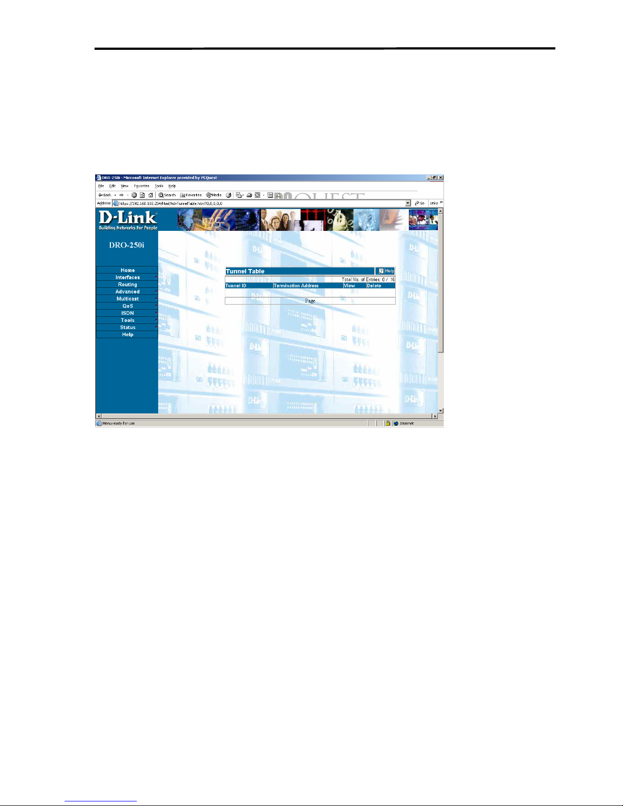
Configuring DRO-250i
3.4.7.3 VPN -Tunnel Table
Click on Advanced > VPN > Tunnel Table to get the web page as shown
below:
The Tunnel Table displays the current tunnel setup. Click on the View
icon corresponding to a given Tunnel ID to display its current Tunnel
Settings. Click on Delete icon to remove the tunnel with its configuration
DRO-250i User Manual
80
Page 82
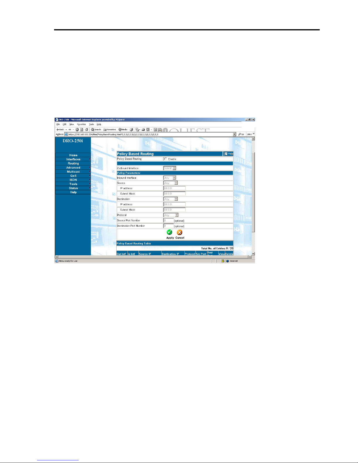
Introduction to DRO-250i
3.4.8 ADVANCED - Load Balancing
3.4.8.1 Load Balancing-Policy Based
Click Advanced >Load balancing>Policy Based to get the web page as
shown below:
Policy-Based Routing enables a user to define policies to achieve efficient
traffic distribution or load balancing. A set of parameters such as Source
IP, Destination IP, Inbound Interface, Protocol and source/Destination
Ports are used to identify and direct the traffic out of a specific Outbound
Interface.
Policy Based Routing: Clicking on this check box will enable Policy
routing in the Router.
Outbound Interface: The network traffic which matches with all the
below policy parameters will be sent out of this interface.
Policy Parameters: These parameters of network traffic are used to
DRO-250i User Manual
81
Page 83

Configuring DRO-250i
identify whether the above configured Outbound Interface should be used
for this traffic.
Inbound Interface: This field sets the policy for the network traffic
which comes into the Router through this interface.
Source: The network traffic's source IP.
1. Any - If Any is set on this field the policy will be applied
on the network traffic regardless of its source IP.
2. Specific - Setting this will allow user to configure specific
Source IP for which the Policy will be applied on the
network traffic.
Destination: The network traffic's destination IP.
1. Any - If Any is set on this field the policy will be applied
on the network traffic regardless of its destination IP.
2. Specific - Setting this will allow user to configure the
specific destination IP for which the Policy will be applied
on the network traffic.
Protocol: The network traffic whose protocol matches with this field will
follow this policy.
Source Port Number: Network traffic uses source port number to specify
the type of application which generated this traffic. This is an optional
field. Only if user specifies a Source Port, the network traffic having this
as its source port will use this policy.
Destination Port Number: Network traffic uses Destination port number
to specify the type of application for which it is destined. This is an
optional field. Only if user specifies a Destination Port, the network traffic
having this as its destination port will use this policy.
DRO-250i User Manual
82
Page 84
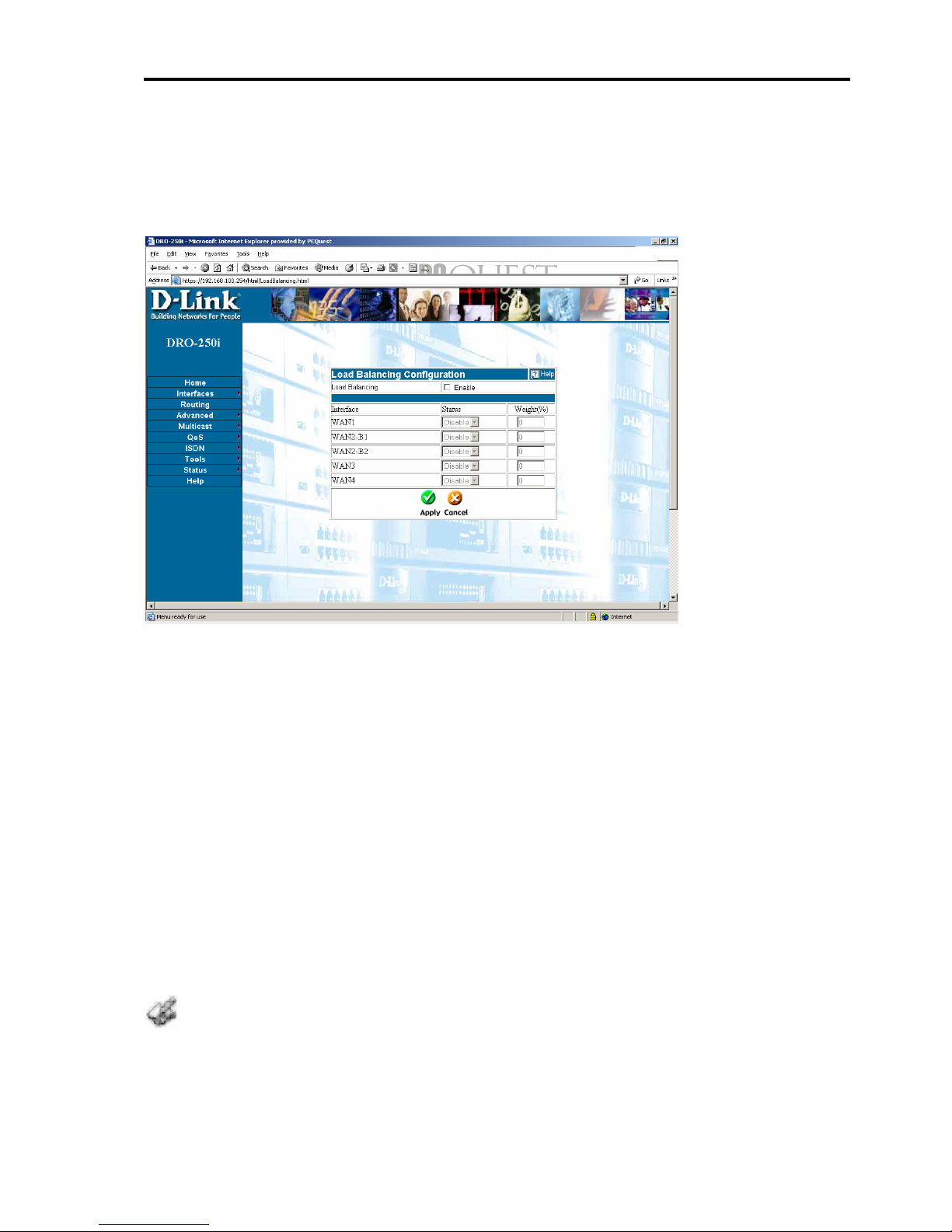
Introduction to DRO-250i
3.4.8.2 Load Balancing-Weight Based
Click Advanced >Load balancing>Weight Based to get the web page as
shown below:
Load-balancing enables a user to distribute internet traffic among multiple
WAN interfaces. User can configure the percentage of traffic to be sent
through a WAN interface.
Load Balancing: Click on this check-box to enable/disable the loadbalancing feature.
Interface: WAN interfaces among which the load must be shared.
Status: Enable/Disable load-balancing on this interface.
Weight: Percentage of the load to be sent through this interface.
1..Sum of weight of all enabled interfaces should be equal to 100.
2. Load Balancing will distribute traffic only via connected interfaces. So for Dialon-demand interfaces, Load Balancing will not work since the interface will never
get connected
DRO-250i User Manual
83
Page 85
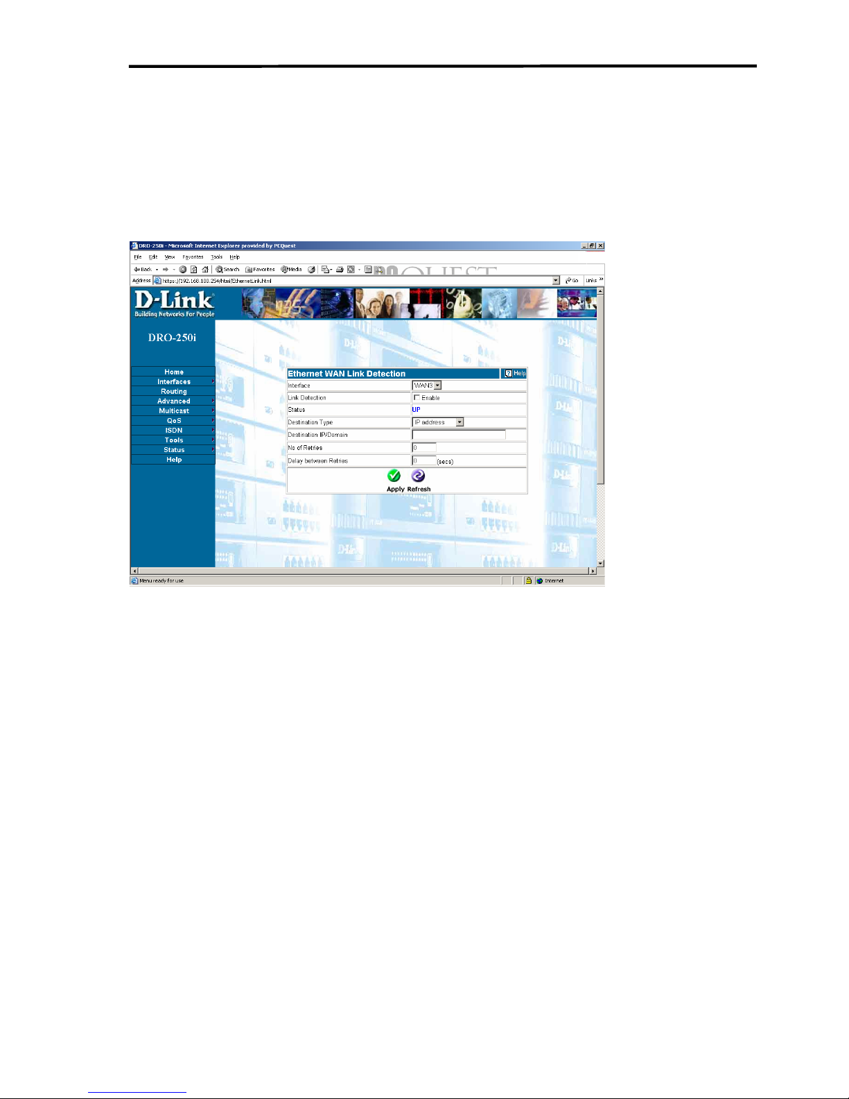
Configuring DRO-250i
3.4.9 ADVANCED – Link Detection
Click ADVANCED > Link Detection to get the web page as shown
below:
This feature enables a user to detect the link status of a particular interface.
Interface: The Ethernet WAN Port on which link detection is to be
performed - WAN3.
Link Detection: Enable/Disable Link Detection on this Interface.
Status: This field displays the current status (UP/DOWN) of the Ethernet
WAN Interface.
Destination Type: The destination can be Domain Name or IP address.
Destination IP/Domain: Domain Name or IP address which is directly
connected to Ethernet WAN. The link is considered UP/DOWN
depending on the reach ability of this Destination.
DRO-250i User Manual
84
Page 86

Introduction to DRO-250i
No of Retries: Number of attempts to reach the specified destination,
before confirming the status (UP/DOWN) of the Link.
Delay between Retries: Time in seconds between retry attempts.
ICMP Ping messages are used to determine the status of the link. So the
destination system should NOT be configured to block ICMP protocol.
DRO-250i User Manual
85
Page 87
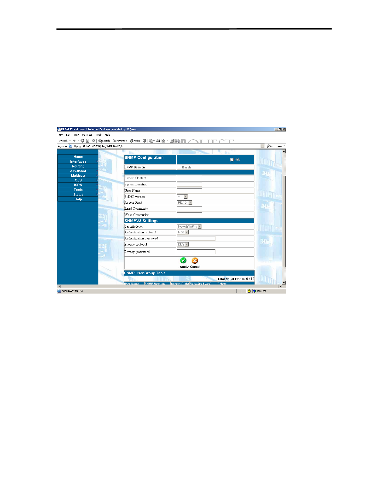
Configuring DRO-250i
3.4.10 ADVANCED – SNMP
3.4.10.1 SNMP-SNMP Configuration
Click ADVANCED > SNMP > SNMP Configuration
to get the web page as shown below:
DRO-250i supports SNMP feature so that user can monitor the device
through any SNMP manager. In the current release, user can only monitor
the device configuration through SNMP.
Status: Enable/Disable User can enable or disable the status of SNMP by
clicking the appropriate button.
System Contact: The value to be given here specifies the contact person
of this device in case of any faults. The name specified here should be of
STRING type.
Example: Administrator (or) concerned person name for this device.
DRO-250i User Manual
86
Page 88

Introduction to DRO-250i
System Location: The physical location of the device is specified here. It
should be of type STRING. The value here specifies
the current location of the device where it is placed.
Example: Second Floor.
User Name: User name should be of STRING type and it should be
Unique. User Name specified with SNMPv3 configuration is used for
authentication also. No two users should have the same name.
Example: John Roberts.
SNMP Version: User can select any of the three versions
SNMPv1,SNMPv2c and SNMPv3.
Access Rights: To browse the MIBs, access rights are provided to the
COMMUNITY. A community can have READ or WRITE access.
READ Community: This defines the COMMUNITY STRING for which
the READ access is given.
WRITE Community: This defines the COMMUNITY STRING for
which the WRITE access is provided. The WRITE community has both
READ as well as WRITE permissions.
READ and WRITE community strings are used for authentication with
SNMPv1 or SNMPv2 only.
SNMPv3 Settings:
Security Level: SNMPv3 provides three types of security levels to its
users which are follows:
NoAuthNoPriv- Uses a username string for authentication.
AuthNoPriv – Provides authentication based on HMAC-MD5 or
HMAC-SHA algorithms.
AuthPriv – Adds DES 56- bit encryption in addition to authentication
based on HMAC-MD5 or HMAC-SHA.
DRO-250i User Manual
87
Page 89

Configuring DRO-250i
Security level for SNMPv1 and SNMPv2 will be NoauthNoPriv. Community
string is used for authentication in these versions
.
Authentication Protocol: The authentication mechanism in SNMPv3
assures that a received message was, in fact, transmitted by the authorized
SNMPv3 user. Protocols used to authenticate SNMPv3 users includes
Message Digest 5(MD5 or Secure Hash Algorithm(SHA).
Authentication Password: This creates an “Authentication Password” for
SNMPv3 users. The pass phrases be at least eight characters long.
Privacy Protocol: The SNMPv3 privacy facility enables managers and
agents to encrypt messages to prevent eavesdropping by third parties. Here
manager entity and agent entity must share a secret key. All the traffic
between them is encrypted using the Data Encryption Standard (DES).
Privacy Password: This sets the DES pass phrase to the SNMPv3 users
which should be at least eight characters long.
DRO-250i User Manual
88
Page 90
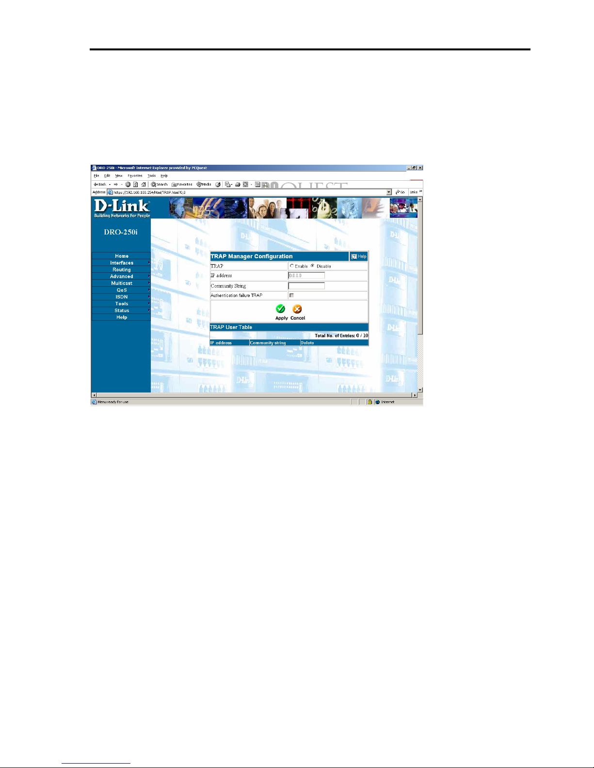
Introduction to DRO-250i
3.4.10.2 SNMP-TRAP Configuration
Click ADVANCED > SNMP > TRAP Configuration
to get the web page as shown below:
TRAP is an “Unsolicited” message sent to the manager by the agent in
case of failure that occurred in the agent. This is to inform the manager
about the agents status. The supported generic Traps in DRO250 are :
Cold Start, Warm Start Authentication Failure.
TRAP Enable/Disable :This option is used by the user to enable/disable
TRAP from the web.
IP address: IP address of the manager to whom traps should be sent.
TRAP Community :A community name should be specified for which
the Traps should be sent. Here the user can specify the community name
for sending Traps. Only the members of this community can be able to
send the Traps.
Authentication TRAP enable /disable: The TRAP which is generated by
the agent during “Authentication Failures”. This is to inform the manager
DRO-250i User Manual
89
Page 91

Configuring DRO-250i
about “UnAuthorized User". This option is used to enable/disable the
authentication trap.
DRO-250i User Manual
90
Page 92
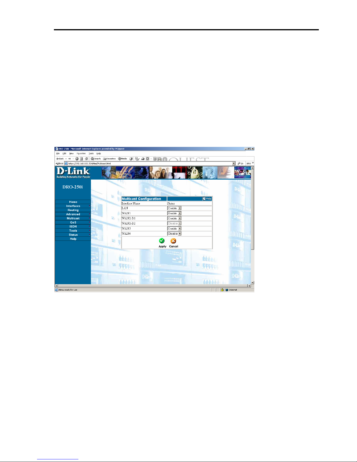
Introduction to DRO-250i
3.5 MULTICAST
3.5.1
MULTICAST – Multicast
User can enable multicast reception on a particular interface. If user
selects disable option on an interface, then it will not accept any multicast
traffic on that interface. So in order to use any multicast application
through DRO-250i, user should enable multicast on a particular interface.
Click on Multicast > Multicast to get the web page as shown below:
DRO-250i User Manual
91
Page 93
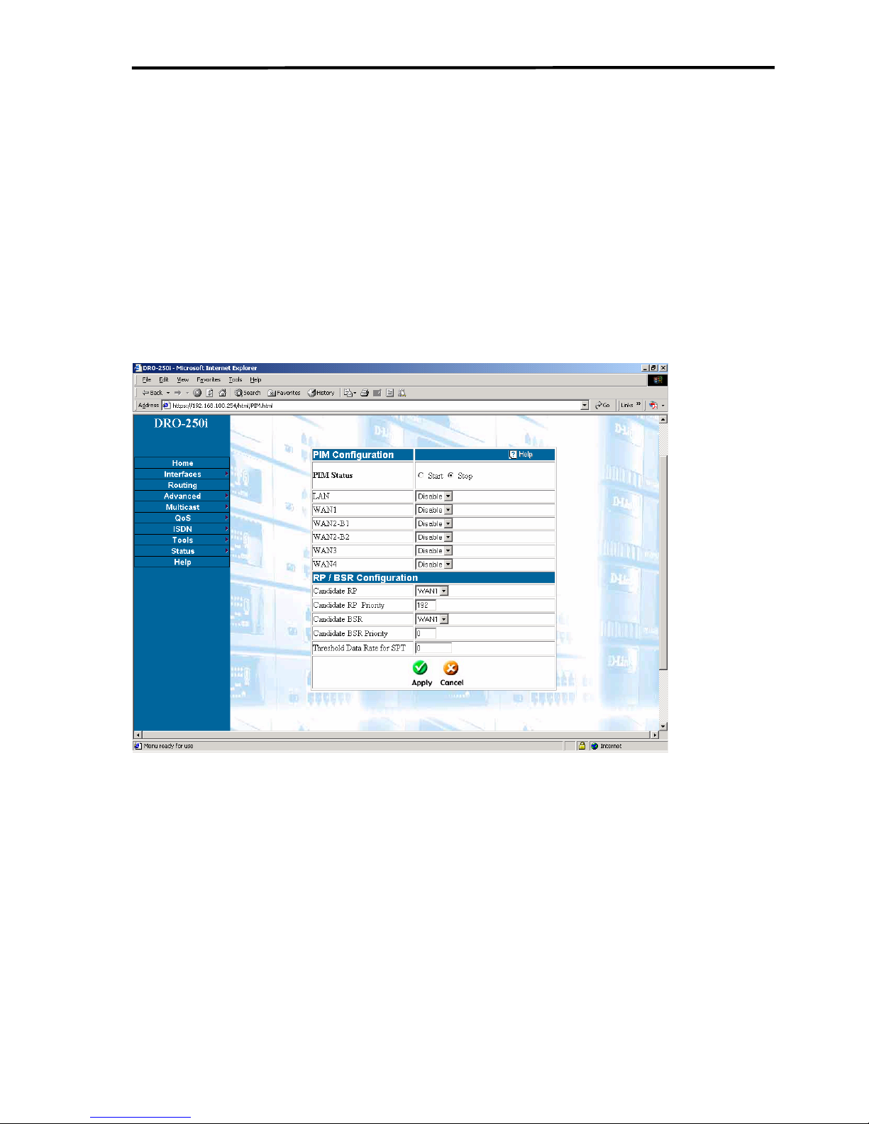
Configuring DRO-250i
3.5.2 MULTICAST - Multicast Routing
If user wants to use any multicast application across the network, then
Multicast Routing should be used. To use multicast routing on a particular
interface, user should first enable Multicast on that interface. If user does
not enable Multicast on any interface, then multicast routing can not be
enabled on that interface.
Click on MULTICAST > Multicast Routing to get the web page as
shown below:
User can enable or disable multicast routing on any interface with the help
of enable or disable option.
Candidate RP : Choose the interface which should become Candidate
RP.
Candidate RP Priority: It is priority which is set for RP (Rendezvous
Point). Lesser number will be higher priority.
Candidate BSR : Choose the interface which should become Candidate
BSR.
DRO-250i User Manual
92
Page 94

Introduction to DRO-250i
Candidate BSR Priority: It is priority which is set for BSR (Bootstrap
Router). Lesser number will be lower priority.
Threshold Data Rate: It is the data rate at which SPT (Source Path Tree)
is formed. If user enters zero, then it will switch to SPT if there is any
traffic. This rate is in Kilo Bytes. The maximum limit is 50,000 KB.
DRO-250i User Manual
93
Page 95
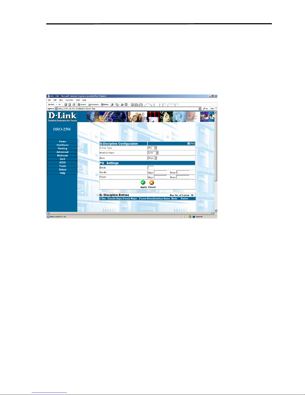
Configuring DRO-250i
3.6 QoS
3.6.1 QoS –Q-Discipline
Click QoS > Q-Discipline to get the web page as shown below:
The basic building block of the Traffic Control system is qdiscs . The
queuing discipline is setup and is given some parameters. Afterwards
packets can be en-queued to them and de-queued from them eg. TBF,
RED. Each device/interface has 1 root qdisc.
Type of Queues:
Egress: It is used to send packets out to the network adaptor. e.g. PrioQ,
RED, TBF.
Priority Queuing (PQ):
Priority queuing (PQ) is the basis for a class of queue scheduling
algorithms that are designed to provide a relatively simple method of
supporting differentiated service classes. In classic PQ, packets are first
classified by the system and then placed into different priority queues.
DRO-250i User Manual
94
Page 96

Introduction to DRO-250i
Packets are scheduled from the head of a given queue only if all queues of
higher priority are empty. Within each of the priority queues, packets are
scheduled in FIFO order.
The PRIO qdisc is a classic queuing discipline that contains an arbitrary
number of classes of different priority. When user creates a new PRIO
queue pfifo sub-queuing disciplines are created depending on number of
bands user is giving. <Bands> number of classes named m:1, m:2 and m:3
etc are created where m is the major number of the queuing discipline &
1,2,3..are minor numbers. Each of these classes are assembled with a pfifo
as its own qdisc.
Bands:
The bands are classes, and are called major:1 to major:3 by default, so if
your PRIO qdisc is called 12:, tc filter traffic to 12:1 (band 0) to grant it
more priority. Reiterating, band 0 goes to minor number 1, band 1 to
minor number 2, etc.
Handle:
Queues are identified by a handle <major number, minor number>, where
the minor number is zero for queues. Handles are used to associate classes
or sub-queues to queuing disciplines.
Parent:
Parent does not apply for root qdisc. Major number represents the parent
of the sub-queue or child queue. This will be equal to the handle major
number of parent queue. Minor number represents the band number of the
sub queue.
Token Bucket Filter (TBF):
Token Bucket Filter is a classless qdisc. It is a simple queue that only
passes packets arriving at a rate which is not exceeding some
administratively set rate, with the possibility to allow short bursts in
excess of his rate. The TBF implementation consists of a buffer (bucket)
DRO-250i User Manual
95
Page 97

Configuring DRO-250i
constantly filled by some virtual pieces of information called tokens, at a
specific rate (token rate). The most important parameter of the bucket is its
size that is the number of tokens it can store.
Handle:
Queues are identified by a handle <major number, minor number>, where
the minor number is zero for queues. Major number uniquely identified
the queue.
Parent:
Parent does not apply for root qdisc.Major number represents the parent of
the sub-queue or child queue. This will be equal to the Handle major
number of parent queue. Parent minor number will be minor number of
the class to whom it (TBF) belongs.
Limit:
Limit is the number of bytes that can be queued waiting for tokens to
become available i.e. maximum amount of time a packet can sit in the
TBF.
Burst:
Burst is the size of the bucket, in bytes. This is the maximum amount of
bytes that tokens can be available instantaneously. In general, larger
shaping rates require a larger buffer. For 10Mbps on Intel, user needs at
least 10kbyte buffer if user wants to reach configured rate. If buffer is too
small, packets may be dropped because more tokens arrive per timer tick
than fit in bucket.
Rate:
Rate of the traffic a qdisc can handle
e.g. TBF can be a child of a PQ, and user can configure by entering values
like rate as 115 Kbps, burst as 5Kb and larency as 70 ms. These value are
given just for an example
DRO-250i User Manual
96
Page 98

Introduction to DRO-250i
Random Early Detection (RED):
Random Early Detection is a classless qdisc which limits its queue size
smartly. Regular queues simply drop packets from the tail when they are
full which may not be the optimal behaviour. RED also performs tail drop
but does so in a more gradual way.
The RED gateway calculates the average queue size using a low pass filter
with an exponential weighted moving average. The average queue size is
compared to two thresholds, a minimum threshold and a maximum
threshold. When the average queue size is less than the minimum
threshold, no packets are marked. When the average queue size is greater
than the maximum threshold every arriving packet is marked
When the average queue size is between the minimum and the maximum
threshold, each arriving packet is marked with probability p, where p is a
function of the average queue size. Each time that a packet is marked, the
probability that a packet is marked from a particular connection is roughly
proportional to that connection's share of the bandwidth
at the gateway.
Handle:
Queues are identified by a handle <major number, minor number>, where
the minor number is zero for queues. Major number uniquely identifies the
queue.
Parent:
Parent does not apply for root qdisc. Major number represents the parent
of the sub-queue or child queue. This will be equal to the handle major
number of parent queue. Parent minor number will be minor number of
the class to whom it (red) belongs.
Min:
Average queue size at which marking becomes a possibility.
Recommended (<Max> - (3 * <Min>)).
DRO-250i User Manual
97
Page 99

Configuring DRO-250i
Max:
At this average queue size, the marking probability is maximal.
Probability:
Maximum probability for marking, specified as a floating point number
from 0.0 to 1.0. Suggested values are 0.01 or 0.02 (1 or 2%, respectively).
Limit:
Hard limit on the real (not average) queue size in bytes. Further packets
are dropped. Should be set 8 * <max>.
Burst:
Used for determining how fast the average queue size is influenced by the
real queue size. Recommended: <burst> = (2 * <min> + <max>) / (3 *
<avpkt>).
Average Packet Size:
Specified in bytes. Used with burst to determine the time constant for
average queue size calculations.
Bandwidth:
This rate is used for calculating the average queue size after some idle
time.
e.g. User can enter the values like limit as 256000 min as 12000, max as
32000 average packet as 1000 burst as 20, probability as 0.02 and
bandwidth as 512. These values
are just to give an idea to the user, so that
user does not enter any wrong range of values.
DRO-250i User Manual
98
Page 100
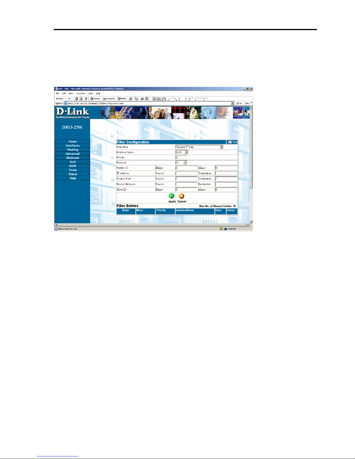
Introduction to DRO-250i
3.6.2 QOS - Filter Configuration
Click QoS > Filter Configuration to get the web page as shown below:
The filter by default supported is u32. Filters are attached to the root qdisc
or a class (parent parameter) to filter the packets that belongs to that
qdisc/class. If the packet matches a filter, it's placed in the class specified
with the flow Id parameter. Each packet that enters the root qdisc must end
in a leaf class to send.
Parent:
Parent ID of the filter is going to be the queue/class identified with the
number major:minor:Parent minor number will always be 0.
Prio:
This is the preference or priority of the filter being added. Prio determines
the order in which filter will be tried. Priority 1 will be the highest.
DRO-250i User Manual
99
 Loading...