

Page 1
Documentation is also available on the D-Link website
Quick Installation Guide
for Switching Redundant
Power Supply
DPS-200A, 500A, 500DC and 700
Getting Started Guide
Erste Schritte
Guide de démarrage
Guida introduttiva
Guía de introducción
Краткое руководство пользователя
快速安裝指南
Page 2
2
ENGLISH
About This Guide
The D-Link DPS-200A, DPS-500A, DPS-500DC, and
DPS-700 are redundant power supplies designed
to be mounted into a standard rack and provide
an affordable solution to provide a constant power
source. This guide gives step-by-step instructions for
setting up the DPS-200A, 500A, 500DC und 700 with
a switch that supports power over a 14-pin or 22-pin
DC power cable. Please note that the model you have
purchased may appear slightly different from those
shown in the illustrations.
For more detailed information about your switch,
its components, making network connections, and
technical specications, please refer to the User’s
Guide included with your switch.
Introduction
A redundant power supply provides a low-cost, simple
solution to the equally simple yet vexing problem of
internal power supply failure, which can result in the
shutdown of a single switching device or an entire
network.
With a redundant power supply connected, an
integrated detection circuit continuously monitors
the switch’s internal power supply. In the event of
a power interruption, the redundant power supply
is immediately triggered so that the switch and
connected devices can continue providing service.
This results in a more reliable network infrastructure
and protects the network from a single failure of a
network device power supply.
Description
The DPS-200A, DPS-500A, DPS-500DC, and
DPS-700 are redundant power supply units designed
to conform to the wattage requirements of the
switches being supported.
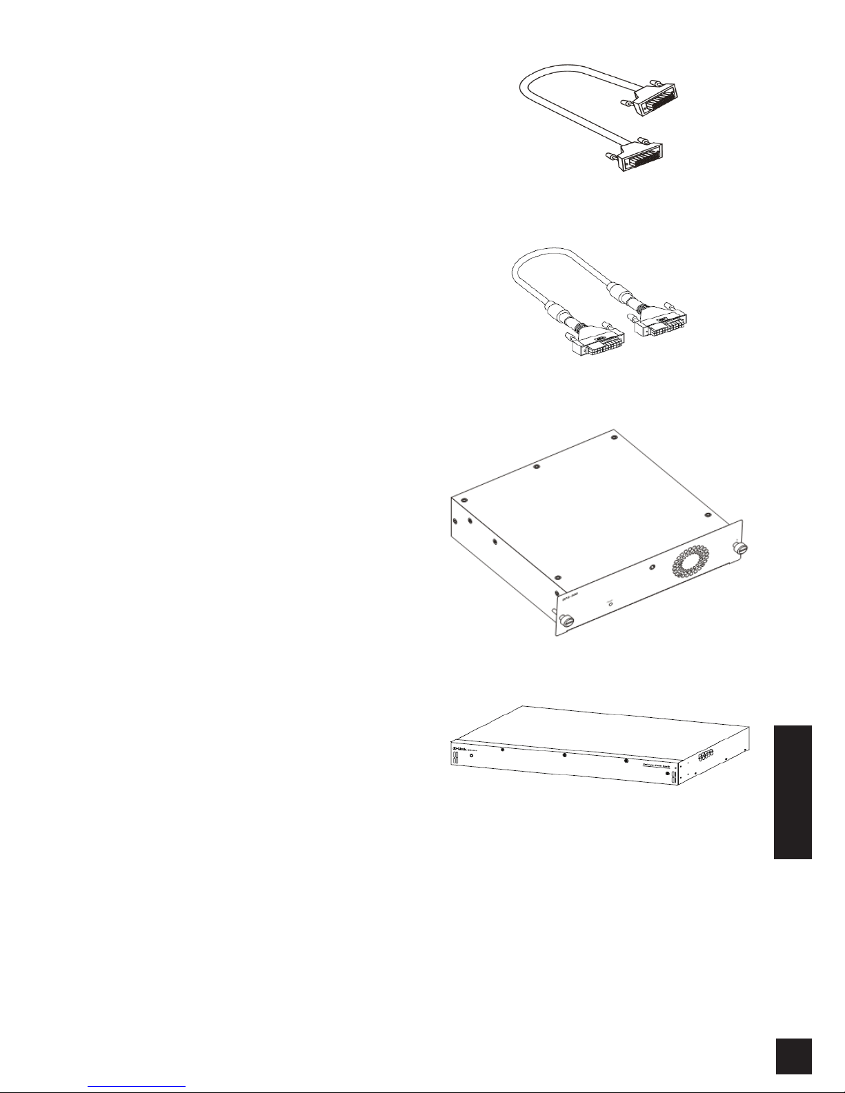
The DPS-200A, DPS-500A and DPS-500DC can
connect to the master switch using a 14-pin DC power
cable while the DPS-700 uses a 22-pin DC power
cable to connect. A standard, three-pronged AC
power cable connects the redundant power supply to
the main power source.
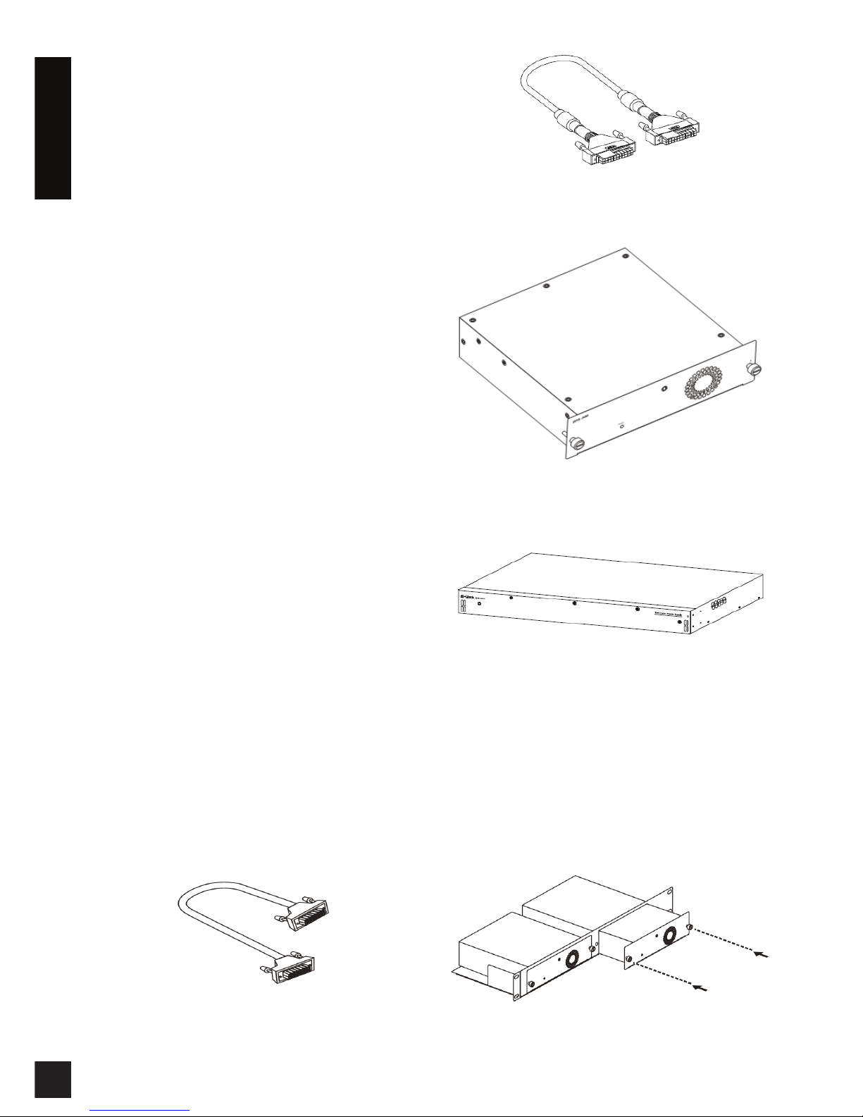
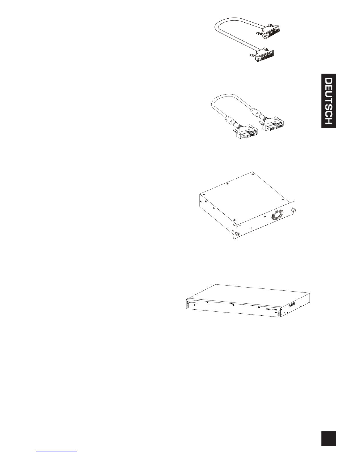
14-pin DC power cable
22-pin DC power cable
Single RPS (DPS-200A/DPS-500A/DPS-500DC)
Single RPS (DPS-700)
Rack Installation
The single RPS DPS-200A, 500A, and 500DC can be
installed into a standard rack via the RPS rack DPS-
800. The DPS-800 is a standard-size rack mount
(1.25U in height) designed to hold up to 2 redundant
power supplies. Installed RPS units can be DPS-
200As, DPS-500As, DPS-500DCs, or a combination
of the above.
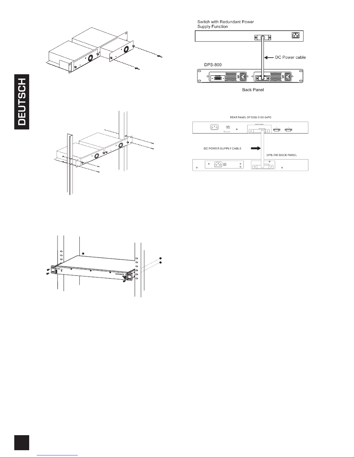
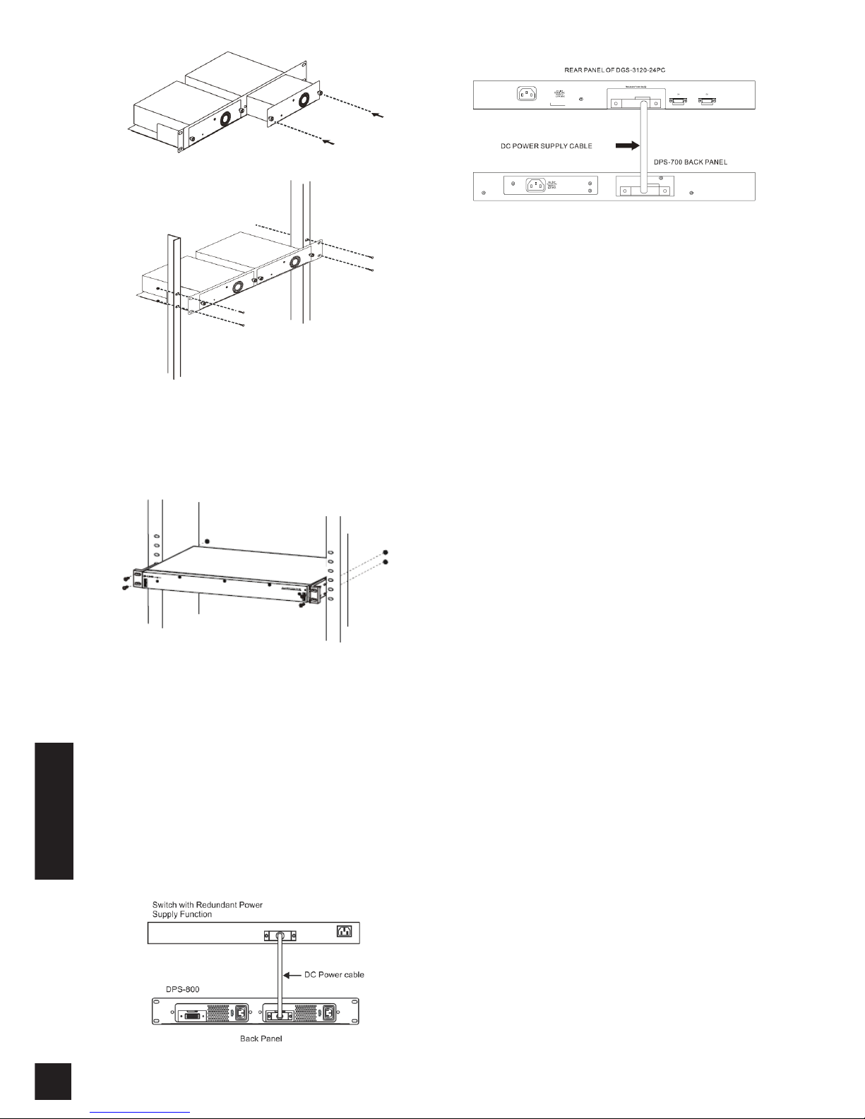
Inserting a single RPS into a DPS-800 RPS rack
Page 3
33
ENGLISH
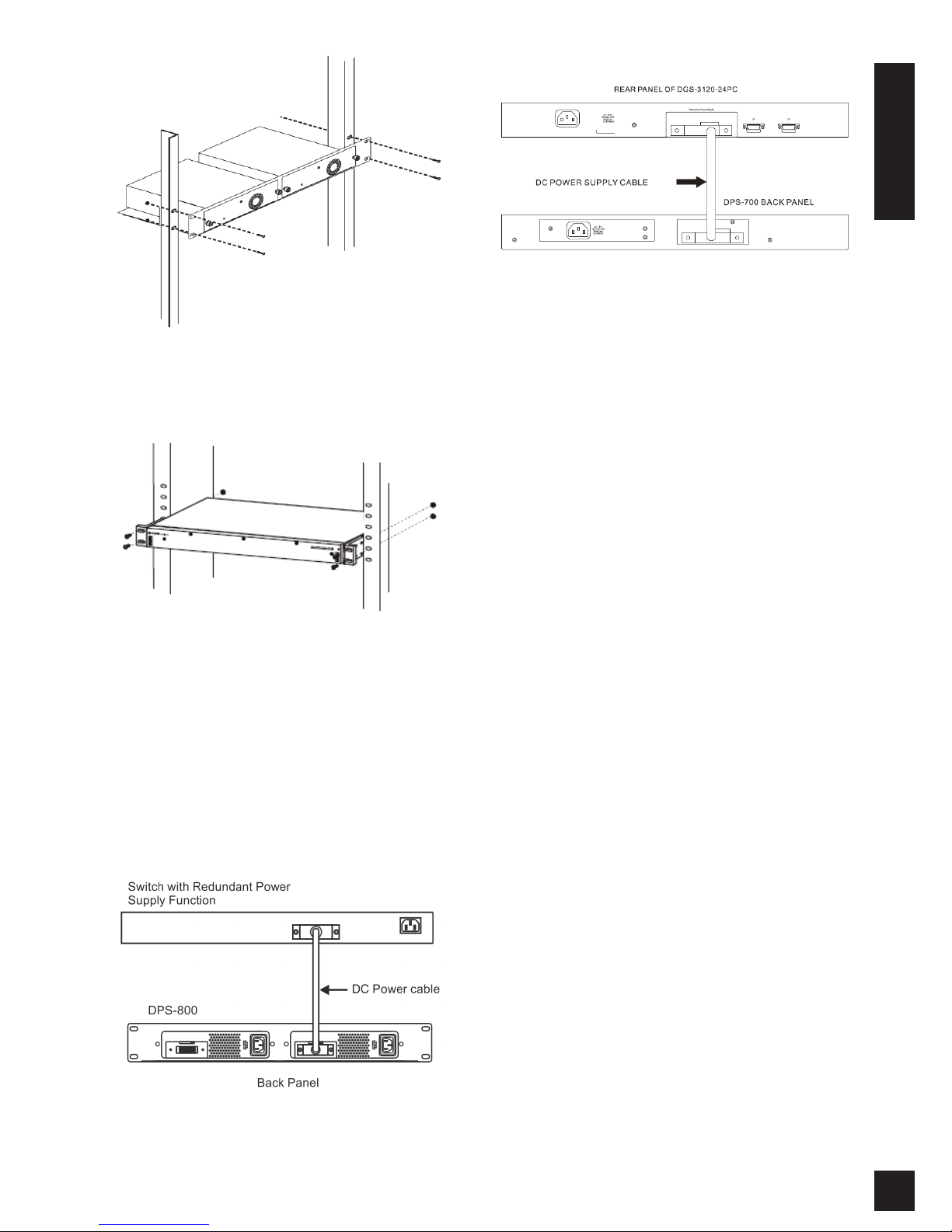
Installing a DPS-800 in a standard electronics rack
The DPS-700 can be installed directly into a standard
rack without the DPS-800.
Installing a DPS-700 in a standard electronics rack
Switch Connection
Caution: The redundant power supply should be
disconnected from its power source before connecting
to the switch. Directly connecting a powered RPS to
the switch may cause damage to the switch’s internal
power supply.
Insert one end of the DC power cable into the
receptacle on the switch and the other end into the
redundant power supply.
Connecting a single RPS in a DPS-800 rack to a switch
Connecting a DPS-700 to a switch
Caution: Do not connect the DPS-700 to the switch
using the 14-pin DC power cable. The equipment may
be damaged if using a 14-pin cable instead of the
correct 22-pin DC power cable.
Power Connection
Connecting AC Power (DPS-200A/500A/700)
Using a standard AC power cable, connect
the redundant power supply to the main AC
power source. A green LED on the front of the
DPS-200A/DPS-500A and DPS-700 will glow to
indicate a successful connection.
Connecting DC Power (DPS-500DC)
1. Firmly attach the DC power source to the
negative and positive contacts on the wiring
assembly.
• The negative pole (-) connects to the
-48V contact.
• The positive pole (+) connects to the
-48V RTN contact.
• If available, an earth ground may be
connected to the center contact post.
2. Tighten the contact screws to secure the
connection.
No change in switch conguration is necessary
when connecting to the RPS.
Page 4
4
ENGLISH
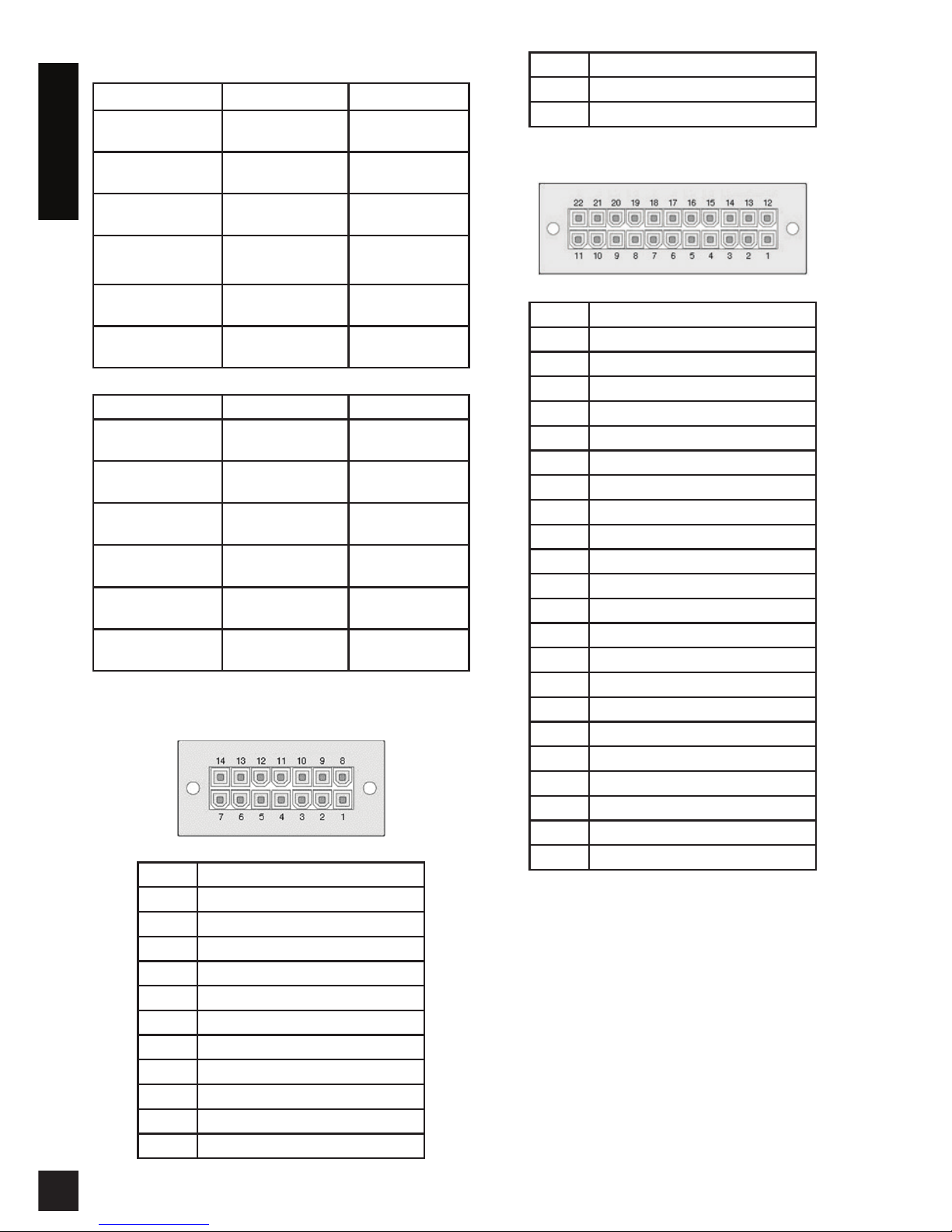
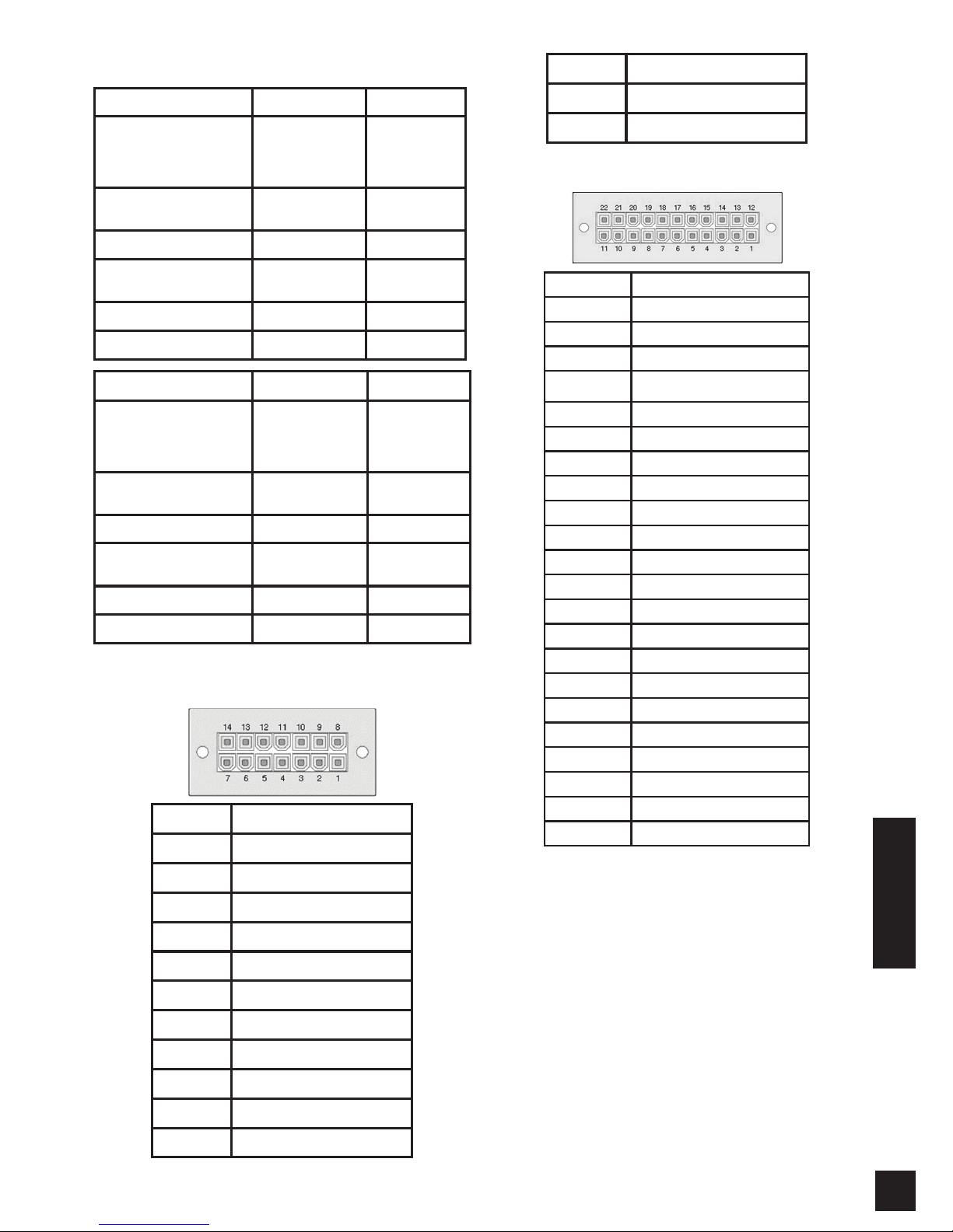
Product Specication
Model Name DPS-200A DPS-500A
Input
Voltage
100 to 240 V AC 100 to 240 V AC
Input
Frequency
50-60 Hz 50-60 Hz
Max Input
Current
2 A 2 A
Output
Voltage
12 V 12 V
Output
Current
13 A 13 A
Operation
Temperature
0 to 50°C 0 to 50°C
Model Name DPS-500DC DPS-700
Input
Voltage
-36 to 72
V DC
90 to 264 V AC
Input
Frequency
- 47-63 Hz
Max Input
Current
6 A 7.5 A
Output
Voltage
12 V 12 V / -54 V
Output
Current
12.5 A 14 A / 7.8 A
Operation
Temperature
0 to 50°C 0 to 65°C
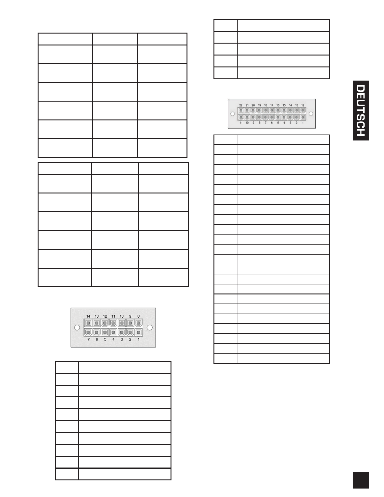
Pin Assignment (DPS-200A/500A/500DCA)
Pin DPS-200A/500A/500DCA
1 GND
2 N/C
3 +12 V
4 +12 V
5 +12 V
6 +12 V
7 GND
8 N/C
9 N/C
10 RPS Present
11 N/C
12 N/C
13 PWR-Good
14 GND
Pin Assignment (DPS-700)
Pin DPS-700
1 -54Vrtn
2 -54V
3 +12 V
4 +12 V
5 +12 V
6 +12 V
7 GND
8 +12VRTNsen
9 LS-54V
10 -54V
11 -54Vrtn
12 GND
13 N/C
14 RPS_Present
15 Status 1
16 Status 2
17 RPS_ Power Good
18 GND
19 +12VRTNsen
20 LS+12V
21 -54Vsen
22 -54VRTNsen
Additional Information
Additional help is available through our ofces
listed at the back of the user manual or online.
To nd out more about D-Link products or
marketing information, please visit the website
http://www.dlink.com.
Warranty Information
The D-Link Limited Lifetime Warranty information is
available at http://warranty.dlink.com/
Page 5
55
Informationen zum Handbuch
Die Geräte DPS-200A, 500A, 500DC und 700 von
D-Link sind redundante, zur Installation in einem
Standardrack ausgelegte Stromversorgungsgeräte
(RPS) und kostengünstige Quellen zur Bereitstellung
ununterbrochener Stromversorgung. Dieser
Leitfaden bietet Ihnen schrittweise durchzuführende
Anleitungen zur Einrichtung der Modelle
DPS-200A, 500A, 500DC und 700 mit einem Switch,
der die Stromzufuhr über ein 14-Pin oder 22-Pin
Gleichstromkabel unterstützt. Bitte beachten Sie,
dass Ihr Modell sich möglicherweise geringfügig von
den Abbildungen unterscheidet.
Nähere Informationen über Ihren Switch und
seine Komponenten sowie zur Herstellung von
Netzwerkverbindungen und zu den entsprechenden
technischen Daten nden Sie im Benutzerhandbuch,
das Ihrem Switch beiliegt.
Einführung
Eine redundante Stromversorgung bietet eine
kostengünstige und einfache Lösung auf das ebenso
einfache, aber leidige Problem eines internen
Stromausfalls, der zum Abschalten eines einzelnen
Schaltgeräts oder zum Ausfall eines gesamten
Netzwerks führen kann.
Durch den Anschluss einer redundanten
Stromversorgung wird die interne
Stromversorgung des Switch durch eine integrierte
Schaltkreiserkennung ununterbrochen überwacht.
Kommt es zum Ausfall der Stromversorgung,
löst dieseer Vorgang sofort ein Einschalten der
redundanten Stromzufuhr aus, sodass der Switch
und die angeschlossenen Geräte ihre Dienste
weiterhin bereitstellen können.
Ergebnis ist eine zuverlässigere
Netzwerkinfrastruktur, die das Netzwerk vor einem
Ausfall der Stromversorgung eines einzelnen
Netzgeräts schützt.
Beschreibung
Der DPS-200A, DPS-500A, DPS-500DC und
700 sind redundante Stromversorgungsgeräte,
die so ausgelegt sind, dass sie den
Wattleistungsanforderungen der Switches
entsprechen.
Das DPS-200A, DPS-500A und das DPS-500DC
können mithilfe eines 14-Pin Gleichstromkabels an
den Master Switch angeschlossen werden. Für das
DPS-700 wird dagegen ein 22-Pin Gleichstromkabel
verwendet. Ein standardmäßiger Schuko-Stecker
verbindet die redundante Stromversorgung mit der
Hauptstromquelle.
14-Pin Gleichstromkabel
22-pin Gleichstromkabel
RPS (Redundantes Einzelnetzteil (DPS-200A /DPS-
500A/DPS-500DC)
RPS (Redundantes Einzelnetzteil (DPS-700))
Rackmontage
Das einzelne RPS DPS-200A, 500A und 500DC
kann im Standardrack über das RPS Rack DPS-800
installiert werden. Bei dem DPS-800 handelt es sich
um ein für 2 redundante Stromversorgungseinheiten
entwickeltes Rack-Montagegehäuse (1 HE
(Höheneinheit/44,45 mm). Für die Installation
geeignete RPS-Geräte können DPS-200As, DPS-
500As, DPS-500DCs oder eine Kombination dieser
Geräte sein.
Page 6
6
Einsetzen eines einzelnen RPS in ein DPS-800 RPS
Rack
Installation eines DPS-800 in ein Standard-Rack
Das DPS-700 kann direkt in einem Standardrack
ohne das DPS-800 installiert werden.
Installation eines DPS-700 in ein Standard-Rack
Switch-Verbindung
Warnhinweis: Die redundante
Stromversorgungseinheit (RPS) sollte von ihrer
Stromquelle getrennt werden, bevor eine Verbindung
zu dem Switch hergestelt wird. Der Direktanschluss
einer eingeschalteten RPS-Einheit mit dem Switch
könnte die interne Stromversorgung des Switch
beschädigen.
Stecken Sie das eine Ende des Gleichstromkabels in
die Buchse am Switch und das andere Ende an die
redundante Stromversorgungseinheit.
Herstellung einer Verbindung einer einzelnen RPSEinheit zu einem Switch in einem DPS-800 Rack
Anschluss eines DPS-700 an einen Switch
Warnhinweis:Verwenden Sie nicht das 14-Pin
Gleichstromkabel für den Anschluss an den DPS-700.
Das könnte das Gerät beschädigen. Verwenden Sie
stattdessen das 22-Pin Gleichstromkabel.
Stromanschluss
Wechselstromanschluss (DPS-200A/500A/700)
Verwenden Sie ein standardmäßiges
Wechselstromkabel, um die redundante
Stromversorgungseinheit an die
Hauptwechselstromquelle anzuschließen. Eine grün
leuchtende LED an der Vorderseite des DPS-200A/
DPS-500A /700 zeigt eine erfolgreiche Verbindung an.
Gleichstromanschluss (DPS-500DC)
1. Schließen Sie die Gleichstromquelle fest an die
negativen (-) und positiven Kontakte (+) des
Kabelbaums an.
• Der Minuspol (-) wird an den -48V Kontakt
angeschlossen.
• Der Pluspol (+) wird an den -48V RTN Kontakt
angeschlossen.
• Falls verfügbar, kann Masse (Schutzerdung) an
den zentralen Kontakt angeschlossen werden
2. Ziehen Sie die Kontaktschrauben zur
Sicherung des Anschlusses fest an.
Es ist keine Änderung der Switch-Konguration beim
Anschluss an die RPS-Einheit erforderlich.
Page 7
77
Produktangaben
Modell DPS-200A DPS-500A
Eingangsspannung
100 bis
240 V AC
100 bis
240 V AC
Eingangs-
frequenz
50-60 Hz 50-60 Hz
Eingangs-
strom
2 A 2 A
Ausgangs-
spannung
12 V 12 V
Ausgangs-
strom
13 A 13 A
Betriebs-
temperatur
0 bis 50°C 0 bis 50°C
Modell DPS-500DC DPS-700
Eingangsspannung
-36 bis
72 V DC
90 bis
264 V AC
Eingangs-
frequenz
- 47-63 Hz
Eingangs-
strom
6 A 7.5 A
Ausgangs-
spannung
12 V 12 V / -54 V
Ausgangs-
strom
12.5 A 14A / 7.8A
Betriebs-
temperatur
0 bis 50°C 0 bis 65°C
Pinbelegung (DPS-200A/500A/500DCA)
Pin DPS-200A/500A/500DCA
1 GND (Masse)
2 N/S
3 +12 V
4 +12 V
5 +12 V
6 +12 V
7 GND (Masse)
8 N/S
9 N/S
10 RPS Präsent
11 N/S
12 N/S
13 PWR-Good
14 GND (Masse)
Pinbelegung (DPS-700)
Pin DPS-700
1 -54Vrtn
2 -54V
3 +12 V
4 +12 V
5 +12 V
6 +12 V
7 GND (Masse)
8 +12VRTNsen
9 LS-54V
10 -54V
11 -54Vrtn
12 GND (Masse)
13 N/C
14 RPS_Present
15 Status 1
16 Status 2
17 RPS_ Power Good
18 GND
19 +12VRTNsen
20 LS+12V
21 -54Vsen
22 -54VRTNsen
Weitere Informationen
Weitere Hilfe und Unterstützung steht Ihnen von
unseren auf der Rückseite des Benutzerhandbuchs
aufgeführten Niederlassungen oder online zur
Verfügung. Wenn Sie an weiteren Einzelheiten zu
den Produkten oder an Marketinginformationen
von
D-Link interessiert sind, besuchen Sie bitte die
Website http://www.dlink.com.
Garantiebestimmungen
Informationen zur eingeschränkten Garantie auf
Lebenszeit für Produkte von D-Link nden Sie unter
http://warranty.dlink.com/
Page 8
8
À Propos de ce Guide
Les périphériques DPS-200A, 500A, 500DC et
700 de D-Link sont des alimentations redondantes
conçues pour être montées dans un rack standard
et offrent une solution économique permettant de
fournir une source d'alimentation constante. Ce
guide fournit des instructions étape par étape pour
la conguration des périphériques DPS-200A, 500A,
500DC et 700 avec un commutateur qui prend en
charge l'alimentation par un câble d’alimentation CC
à 14 broches ou 22 broches. Notez que le modèle
que vous avez acheté peut légèrement différer de
celui illustré sur les gures.
Pour de plus amples informations sur votre
commutateur, ses composants, sa connexion
au réseau et ses caractéristiques techniques,
veuillez consulter le guide d’utilisation fourni avec le
commutateur.
Introduction
Une alimentation redondante fournit une solution
simple et économique au problème tout aussi simple,
mais frustrant de panne d'alimentation interne,
qui peut provoquer l'arrêt d'un seul dispositif de
commutation ou d'un réseau entier.
Lorsqu'une alimentation redondante est connectée,
un circuit de détection intégré surveille en
permanence l'alimentation interne du commutateur.
En cas d'interruption de l'alimentation, l'alimentation
redondante est immédiatement déclenchée an
que le commutateur et les périphériques connectés
puissent continuer à fournir des services.
Cela se traduit par une infrastructure de réseau
plus able et protège le réseau contre la panne
d'alimentation d'un seul périphérique réseau.
Description
Les périphériques DPS-200A, 500A, 500DC et 700
sont des unités d'alimentation redondantes conçues
pour se conformer à la puissance en watts requise
des commutateurs pris en charge.
Vous pouvez connecter les DPS-200A, DPS-500A
et DPS-500DC au commutateur à l’aide d’un câble
d’alimentation CC à 14 broches alors que le DPS-700
utilise un câble d’alimentation CC à 22 broches. Un
câble d’alimentation CA triphasé standard permet
de connecter l’alimentation redondante à la source
d’alimentation principale.
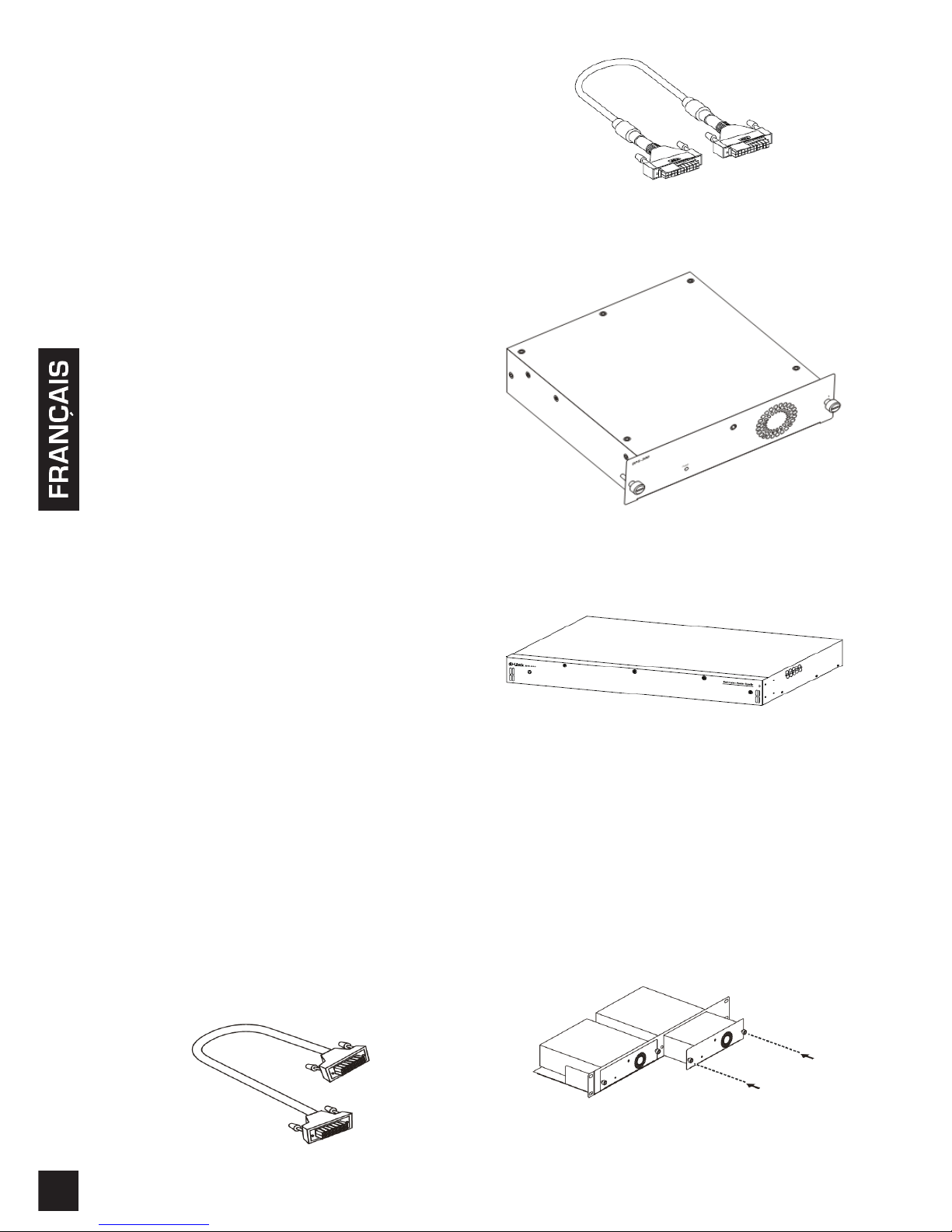
Câble d’alimentation CC à 14 broches
Câble d’alimentation CC à 22 broches
Alimentation redondante (RPS) simple (DPS-200A /
DPS-500A/DPS-500DC)
Alimentation redondante (RPS) simple (DPS-700)
Installation du rack
Les alimentations redondantes (RPS) simples
DPS-200A, 500A et 500DC peuvent être installées
dans le rack standard via le rack RPS DPS-800. Le
DPS-800 est un rack de taille standard (1,25 U en
hauteur) conçu pour contenir jusqu'à 2 alimentations
redondantes. Les unités RPS installées peuvent être
des DPS-200A, DPS-500A, DPS-500DC, ou une
combinaison de ces unités.
Insertion d'une alimentation redondante (RPS) simple
dans un rack RPS DPS-800
Page 9
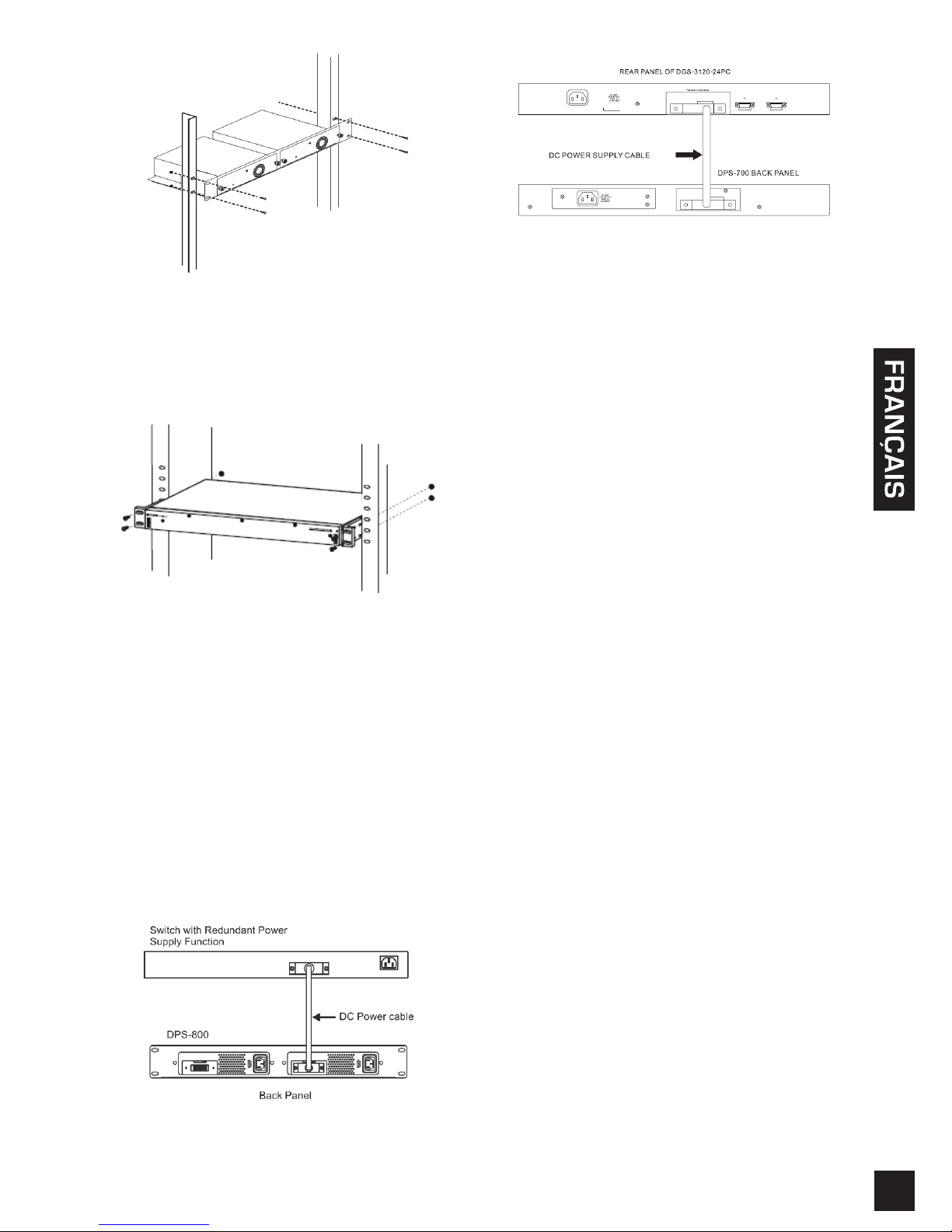
99
Installation d’un DPS-800 dans un rack électronique
standard
Le DPS-700 peut être installé directement dans un
rack standard sans le DPS-800.
Installation d’un DPS-700 dans un rack électronique
standard
Connexion à un commutateur
Attention : L'alimentation redondante doit être
débranchée de sa source d'alimentation avant
de la connecter au commutateur. La connexion
directe d'une RPS alimentée au commutateur
peut endommager l'alimentation interne du
commutateur.
Insérez une extrémité du câble d'alimentation CC
dans la che située sur le commutateur et l'autre
extrémité dans l’alimentation redondante.
Connexion d'une RPS simple se trouvant dans un
rack RPS DPS-800 à un commutateur
Connexion d'un DPS-700 à un commutateur
Attention: Ne connectez pas le DPS-700 à un
commutateur à l’aide d’un câble d’alimentation CC
à 14 broches. L’utilisation de ce câble, au lieu du
câble d’alimentation CC à 22 broches correct, risque
d’endommager l’équipement.
Connexion de l'alimentation
Connexion du courant alternatif
(DPS-200A/500A/700)
Utilisez un câble d’alimentation CA standard pour
connecter l’alimentation redondante à la source
d’alimentation CA principale. Un voyant vert à
l'avant de l'alimentation redondante DPS-200A/
DPS-500A/700 s'allume pour indiquer une connexion
réussie.
Connexion du courant CC (DPS-500DC)
1. Connectez fermement la source d'alimentation CC
aux contacts négatif et positif du câblage.
• Le pôle positif (+) se connecte au contact de
-48 V.
• Le pôle positif (-) se connecte au contact retour
de -48 V.
• Le cas échéant, une terre peut être connectée au
poste de contact central.
2. Serrez les vis de contact pour sécuriser la
connexion.
Aucun changement dans la conguration du
commutateur n'est requis lors de la connexion à
l'alimentation redondante (RPS).
Page 10
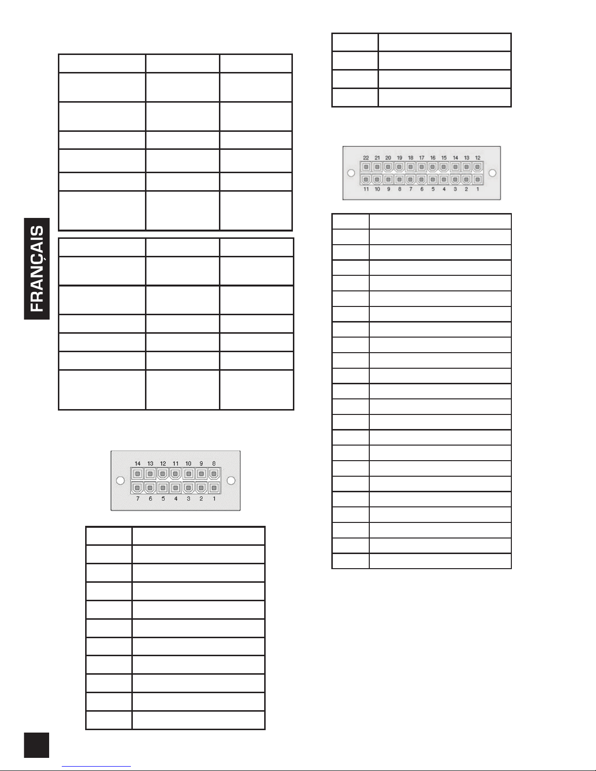
10
Caractéristiques du produit
Nom du modèle DPS-200A DPS-500A
Tension d'entrée
100 à
240 V CA
100 à
240 V CA
Fréquence
d'entrée
50-60 Hz 50-60 Hz
Courant d'entrée 2 A 2 A
Tension de sortie 12 V 12 V
Courant de sortie 13 A 13 A
Température
de
fonctionnement
0 à 50°C 0 à 50°C
Nom du modèle DPS-500DC DPS-700
Tension d'entrée
-36 à
72 V CC
90 à
264 V CA
Fréquence
d'entrée
- 47-63 Hz
Courant d'entrée 6 A 7.5 A
Tension de sortie 12 V 12 V / -54 V
Courant de sortie 12.5 A 14A / 7.8A
Température
de
fonctionnement
0 à 50°C 0 à 65°C
Affectation des broches
(DPS-200A/500A/500DCA)
Broche DPS-200A/500A/500DCA
1 Terre
2 N/C
3 +12 V
4 +12 V
5 +12 V
6 +12 V
7 Terre
8 N/C
9 N/C
10 RPS présente
11 N/C
12 N/C
13 PWR-Good
14 Terre
Affectation des broches (DPS-700)
Pin DPS-700
1 -54Vrtn
2 -54V
3 +12 V
4 +12 V
5 +12 V
6 +12 V
7 Terre
8 +12VRTNsen
9 LS-54V
10 -54V
11 -54Vrtn
12 Terre
13 N/C
14 RPS_Present
15 État 1
16 État 2
17 RPS_ Power Good
18 Terre
19 +12VRTNsen
20 LS+12V
21 -54Vsen
22 -54VRTNsen
Informations complémentaires
Vous trouverez une aide supplémentaire auprès de nos
bureaux répertoriés au dos du manuel de l'utilisateur et
en ligne. Pour en savoir plus sur les produits D-Link ou
pour obtenir des informations commerciales, consultez
le site Web http://www.dlink.com.
Informations sur la garantie
Les informations relatives à la garantie limitée dans le
temps D-Link sont disponibles à l’adresse suivante :
http://warranty.dlink.com/
Page 11
1111
Acerca de esta guía
Las DPS-200A, 500A,500DC y 700 de D-Link son
fuentes de alimentación redundantes diseñadas para
que se monten en un estante estándar y proporcionen
una solución rentable con el n de ofrecer una
fuente de alimentación constante. Esta guía le
ofrece instrucciones paso a paso para congurar las
DPS-200A, 500A,500DC y 700 con un conmutador
que admita la alimentación a través de un cable de
alimentación de CC de 14 patillas o 22 patillas. Tenga
en cuenta que el modelo que ha adquirido puede
tener un aspecto ligeramente diferente al mostrado en
las ilustraciones.
Para obtener información más detallada acerca
del conmutador, sus componentes, la realización
de conexiones de red y las especicaciones
técnicas, consulte la Guía del usuario incluida con el
conmutador.
Introducción
Una fuente de alimentación redundante proporciona
una solución sencilla y barata al problema igualmente
sencillo aunque irritante del fallo de la fuente de
alimentación interna, que puede provocar el cierre de
un único dispositivo de conmutación o de toda la red.
Con una fuente de alimentación redundante
conectada, un circuito de detección integrado
supervisa de forma continua la fuente de alimentación
interna del conmutador. En caso de una interrupción
de la alimentación, la fuente de alimentación
redundante se activa inmediatamente para que el
conmutador y los dispositivos conectados puedan
seguir proporcionando servicio.
Esto se traduce en una infraestructura de red
más able y protege a la red frente a un fallo de la
fuente de alimentación de un dispositivo de red.
Descripción
Las DPS-200A, DPS-500A, DPS-500DC y DPS-700
son fuentes de alimentación redundantes diseñadas
para cumplir los requisitos de potencia en vatios de
los conmutadores admitidos.
Las DPS-200A, DPS-500A y DPS-500DC se pueden
conectar al conmutador mediante un cable de
alimentación de CC de 14 patillas, mientras que la
DPS-700 utiliza un cable de alimentación de CC de
22 patillas para conectarse. Por el otro lado, un cable
de alimentación de tres clavijas estándar conecta
la fuente de alimentación redundante a la toma de
corriente alterna principal.
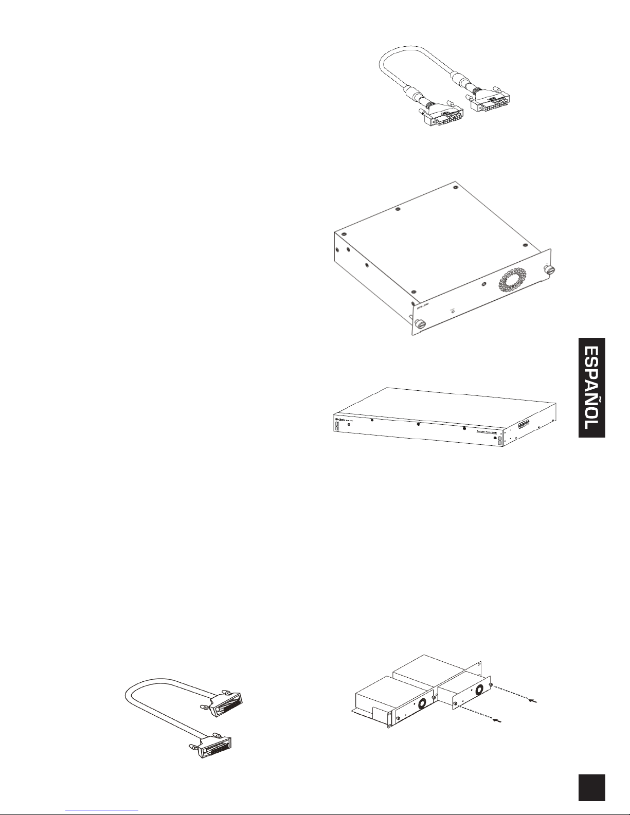
Cable de alimentación de CC de 14 patillas
Cable de alimentación de CC de 22 patillas
RPS individual (DPS-200A /DPS-500A/DPS-500DC)
RPS individual (DPS-700)
Instalación en bastidor
La RPS individual DPS-200A, 500A y 500DC se
puede instalar en un estante estándar utilizando
el estante de RPS DPS-800. El DPS-800 es un
montaje en estante de tamaño estándar (altura de
1,25U) diseñado para sostener hasta 2 fuentes
de alimentación redundantes. Las unidades RPS
instaladas pueden ser de tipo DPS-200A, DPS-500A,
DPS-500DC, o una combinación de las mismas.
Inserción de un RPS individual en un estante DPS-800
para RPS
Page 12
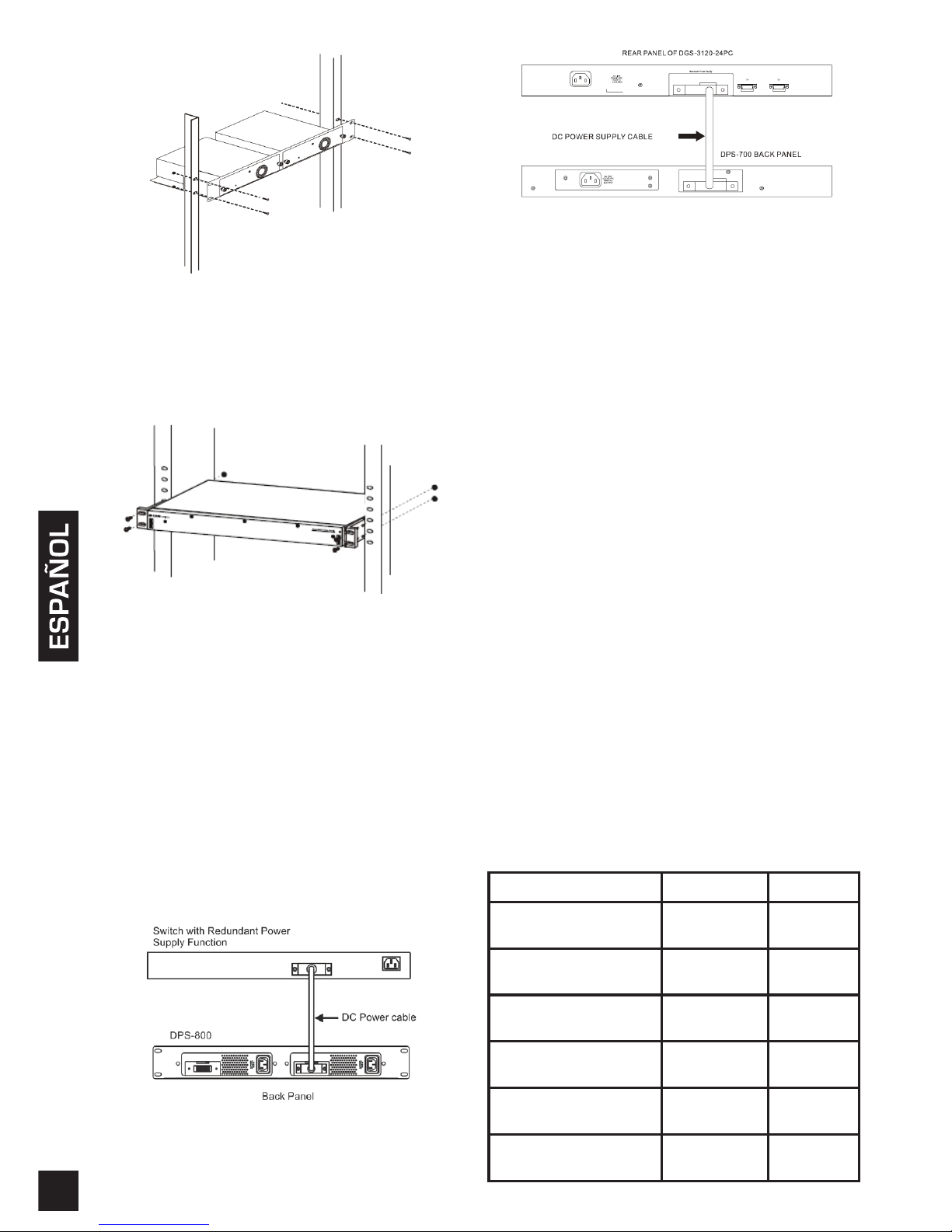
12
Instalación de un DPS-800 en un estante para
dispositivos electrónicos estándar
La DPS-700 se puede instalar directamente en un
estante estándar sin el DPS-800.
Instalación de un DPS-700 en un estante para
dispositivos electrónicos estándar
Conexión del conmutador
Precaución: Se debe desconectar la fuente
de alimentación redundante de su fuente de
alimentación antes de conectarla al conmutador.
Conectar directamente una RPS encendida al
conmutador puede causar daños en la fuente de
alimentación interna del conmutador.
Inserte un extremo del cable de alimentación de
CC en el receptáculo del conmutador y el otro
extremo en la fuente de alimentación redundante.
Conexión de una RPS individual en un estante
DPS-800 a un conmutador
Conexión de un DPS-700 a un conmutador
Precaución: No conecte el DPS-700 al conmutador
utilizando un cable de alimentación CC de 14 patillas. El
equipo se podría dañar si se utiliza este cable en lugar
del cable de alimentación CC de 22 patillas correcto.
Conexión de alimentación
Conexión de la alimentación de CA (DPS200A/500A/700)
Utilizando un cable de alimentación de CA estándar,
conecte la fuente de alimentación redundante a la
fuente de alimentación de CA principal. En parte
frontal de la DPS-200A/DPS-500A/700 se encenderá
un LED verde para indicar que la conexión es
correcta.
Conexión de la alimentación de CC (DPS-500DC)
1. Acople rmemente la fuente de alimentación de CC
a los contactos negativos y positivos del conjunto de
cables.
• El polo negativo (-) se conecta al contacto de -48 V.
• El polo positivo (+) se conecta al contacto RTN de
-48 V.
• Si está disponible, se puede conectar una toma de
tierra al poste de contacto central.
2. Apriete los tornillos de contacto para asegurar la
conexión.
No es necesario realizar ningún cambio en la
conguración del conmutador al conectarlo a la RPS.
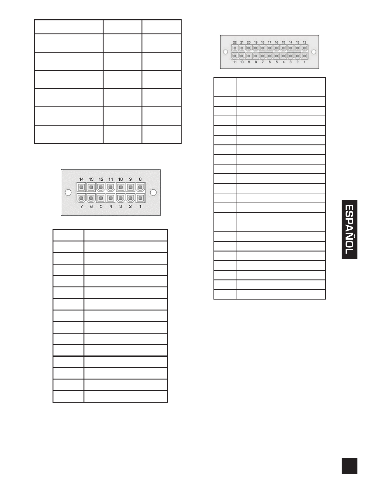
Especicaciones del producto
Nombre del modelo DPS-200A DPS-500A
Entrada
Voltaje
100 a 240
V CA
100 a 240
V CA
Entrada
Frecuencia
50-60 Hz 50-60 Hz
Entrada
Actual
2 A 2 A
Salida
Voltaje
12 V 12 V
Salida
Actual
13 A 13 A
Funcionamiento
Temperatura
0 a 50°C 0 a 50°C
Page 13
1313
Nombre del modelo DPS-500DC DPS-700
Entrada
Voltaje
-36 a 72
V CC
90 a
264 V CA
Entrada
Frecuencia
- 47-63 Hz
Entrada
Actual
6 A 7.5 A
Salida
Voltaje
12 V 12 V / -54 V
Salida
Actual
12.5 A 14A / 7.8A
Funcionamiento
Temperatura
0 a 50°C 0 a 65°C
Asignación de pin (DPS-200A/500A/500DCA)
Pin DPS-200A/500A/500DCA
1 Toma de tierra
2 N/C
3 +12 V
4 +12 V
5 +12 V
6 +12 V
7 Toma de tierra
8 N/C
9 N/C
10 RPS presente
11 N/C
12 N/C
13 ALIMENTACIÓN correcta
14 Toma de tierra
Asignación de pin (DPS-700)
Pin DPS-700
1 rtn de -54 V
2 -54V
3 +12 V
4 +12 V
5 +12 V
6 +12 V
7 Toma de tierra
8 sen RTN de +12 V
9 LS-54V
10 -54V
11 -54Vrtn
12 Toma de tierra
13 N/C
14 RPS_presente
15 Estado 1
16 Estado 2
17 RPS_ alimentación correcta
18 Toma de tierra
19 sen RTN de +12 V
20 LS+12V
21 sen de -54 V
22 sen RTN de -54 V
Información adicional
Existe ayuda adicional disponible a través de
nuestras ocinas, que aparecen enumeradas en la
contraportada del manual de usuario o en línea. Para
encontrar más información acerca de los productos
D-Link o su comercialización, visite el sitio web http://
www.dlink.com.
Información acerca de la
garantía
La información sobre la Garantía limitada de D-Link
está disponible en http://warranty.dlink.com/
Page 14
14
Informazioni sulla guida
I dispositivi D-Link DPS-200A, 500A, 500DC e 700
sono alimentatori ridondanti progettati per il montaggio
in un rack standard e costituiscono una soluzione
conveniente per disporre di una fonte di alimentazione
costante. In questa guida vengono fornite istruzioni
dettagliate per congurare il dispositivo DPS-200A,
500A, 500DC e700 con uno switch alimentato tramite
un cavo di alimentazione CC a 14 pin o 22 pin. Notare
che il modello acquistato potrebbe essere leggermente
diverso da quello rafgurato nelle illustrazioni.
Per informazioni più dettagliate sullo switch e i relativi
componenti, nonché sui collegamenti di rete e le
speciche tecniche, fare riferimento alla Guida per
l'utente fornita con lo switch.
Introduzione
Un alimentatore ridondante costituisce una soluzione
semplice e a costi contenuti per ovviare al problema,
ugualmente semplice ma fastidioso, delle interruzioni
dell'alimentazione interne, che possono causare lo
spegnimento di un singolo dispositivo di switching o
di un'intera rete.
Collegando un alimentatore ridondante, un circuito
di rilevamento integrato controlla continuamente
l'alimentatore interno dello switch. In caso di interruzione
dell'alimentazione, viene immediatamente attivato
l'alimentatore ridondante, in modo tale che lo switch e
i dispositivi collegati possano continuare a funzionare.
Si otterrà in questo modo un'infrastruttura di rete più
afdabile e la rete risulterà protetta da singoli guasti di
un alimentatore dei dispositivi di rete.
Descrizione
I dispositivi DPS-200A, DPS-500A, DPS-500DC e
DPS-700 sono alimentatori ridondanti progettati per
garantire la conformità ai requisiti di wattaggio degli
switch supportati.
I dispositivi DPS-200A, DPS-500A e DPS-500DC
possono essere collegati allo switch master con un
cavo di alimentazione CC a 14 pin, mentre per il
dispositivo DPS-700 ne viene utilizzato uno CC a 22
pin. Per collegare invece l'alimentatore ridondante
(RPS) alla presa elettrica.
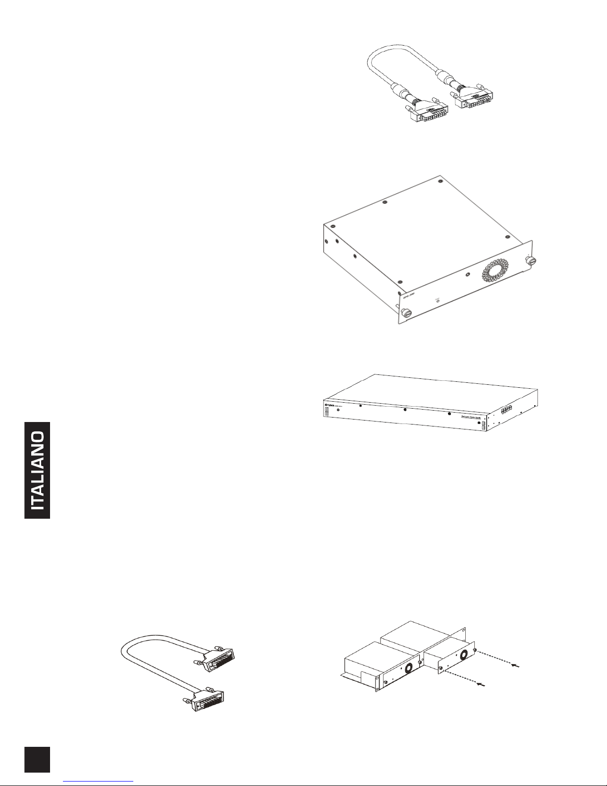
Cavo di alimentazione CC a 14 pin
Cavo di alimentazione CC a 22 pin
Singolo RPS (DPS-200A /DPS-500A/DPS-500DC)
Singolo RPS (DPS-700)
Installazione in rack
I singoli dispositivi RPS DPS-200A, 500A e 500DC
possono essere installati nel rack standard tramite
il rack per RPS DPS-800. Il dispositivo DPS-800 è
un dispositivi per il montaggio in rack di dimensioni
standard (1,25U in altezza) concepito per alloggiare
no a due alimentatori ridondanti. È possibile
installare le unità RPS DPS-200A, DPS-500A, DPS500DC oppure una combinazione di questi modelli.
Inserimento di un singolo RPS in un rack per RPS
DPS-800
Page 15
1515
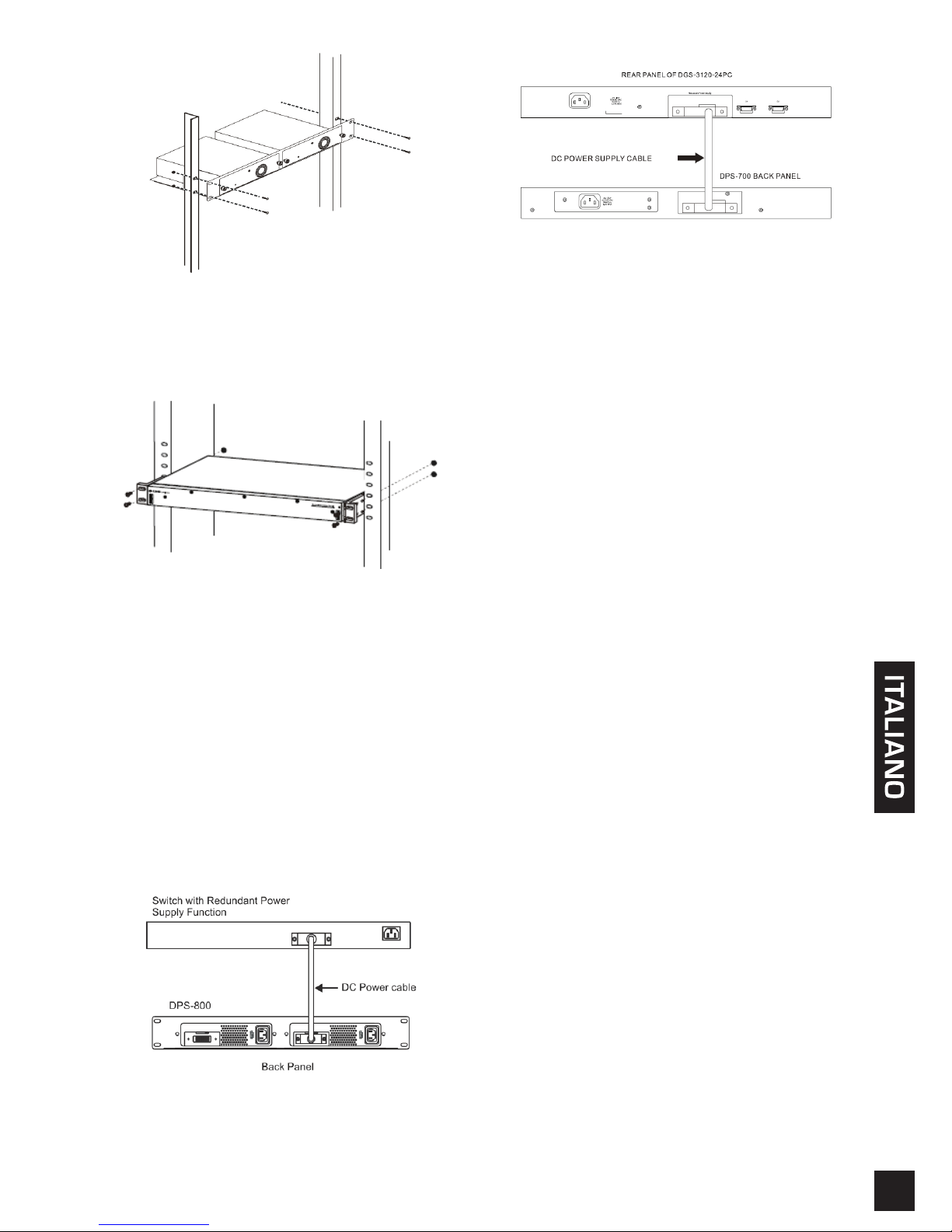
Installazione di un dispositivo DPS-800 in un rack per
componenti elettronici standard
Il dispositivo DPS-700 può essere installato in un rack
standard senza il dispositivo DPS-800.
Installazione di un dispositivo DPS-700 in un rack per
componenti elettronici standard
Collegamento agli switch
Attenzione: Prima del collegamento allo switch,
è necessario scollegare l'alimentatore ridondante
dalla relativa presa elettrica. Il collegamento
diretto di un dispositivo RPS alimentato allo
switch può danneggiare l'alimentatore interno
dello switch.
Inserire un'estremità del cavo di alimentazione
CC nella presa sullo switch e l'altra estremità
nell'alimentatore ridondante.
Inserimento di un singolo RPS in un rack per RPS
DPS-800
Collegamento del dispositivo DPS-700 a uno switch
Attenzione: non collegare il dispositivo DPS-700 allo
switch utilizzando il cavo di alimentazione CC a 14 pin.
È possibile danneggiare l'apparecchiatura se si utilizza
questo cavo anziché quello CC a 22 pin corretto.
Connettore di alimentazione
Collegamento dell'alimentazione CA (DPS200A/500A/700)
Collegare l'alimentatore ridondante alla presa elettrica
CA utilizzando un cavo di alimentazione CA standard.
L'accensione di un LED verde nella parte anteriore
del dispositivo DPS-200A/DPS-500A/700 indicherà la
corretta connessione.
Collegamento dell'alimentazione CC (DPS-500DC)
1. Collegare saldamente la fonte di alimentazione CC
ai contatti positivo e negativo del cablaggio. .
• Il polo negativo (-) deve essere collegato al
contatto da -48 V.
• Il polo positivo (+) deve essere collegato al
contatto RTN da -48 V.
• Se disponibile, è possibile collegare la messa a
terra al contatto centrale.
2. Serrare le viti dei contatti per ssare il
collegamento.
Per il collegamento al dispositivo RPS, non è
necessario modicare la congurazione dello switch.
Page 16
16
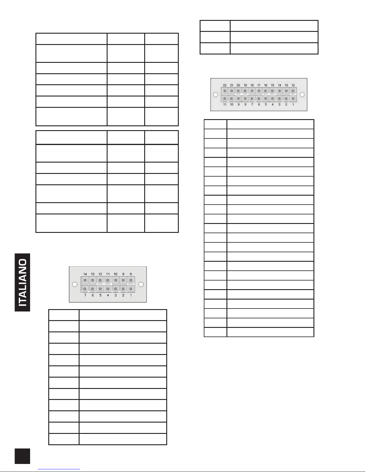
Speciche del prodotto
Nome modello DPS-200A DPS-500A
Ingresso Tensione
Da 100 a
240 V CA
Da 100 a
240 V CA
Ingresso Frequenza 50-60 Hz 50-60 Hz
Ingresso Corrente 2 A 2 A
Uscita Tensione 12 V 12 V
Uscita Corrente 13 A 13 A
Operazione
Temperatura
Da 0 a
50 °C
Da 0 a
50 °C
Nome modello DPS-500DC DPS-700
Ingresso Tensione
Da -36 a
72 V CC
Da 90 a
264 V CA
Ingresso Frequenza - 47-63 Hz
Ingresso Corrente 6 A 7.5 A
Uscita Tensione 12 V
12 V /
-54 V
Uscita Corrente 12.5 A 14A / 7.8A
Operazione
Temperatura
Da 0 a
50 °C
Da 0 a
65°C
Assegnazione dei pin
(DPS-200A/500A/500DCA)
Pin DPS-200A/500A/500DCA
1 GND
2 N/C
3 +12 V
4 +12 V
5 +12 V
6 +12 V
7 GND
8 N/C
9 N/C
10 RPS Present
11 N/C
12 N/C
13 PWR-Good
14 GND
Assegnazione dei pin (DPS-700)
Pin DPS-700
1 -54Vrtn
2 -54V
3 +12 V
4 +12 V
5 +12 V
6 +12 V
7 GND
8 +12VRTNsen
9 LS-54V
10 -54V
11 -54Vrtn
12 GND
13 N/C
14 RPS_Presente
15 Stato 1
16 Stato 2
17 RPS_Alimentazione adeguata
18 GND
19 +12VRTNsen
20 LS+12V
21 -54Vsen
22 -54VRTNsen
Ulteriori informazioni
Per ulteriore supporto è possibile rivolgersi agli ufci il
cui elenco è riportato sul retro del manuale dell'utente
o è disponibile online. Per ulteriori informazioni sui
prodotti D-Link o per la documentazione marketing,
visitare il sito Web all'indirizzo http://www.dlink.com.
Termini di garanzia
Per informazioni sulla garanzia limitata D-Link, visitare
il sito all'indirizzo http://warranty.dlink.com/
Page 17
1717
РУССКИЙ
О данном руководстве
D-Link DPS-200A, DPS-500A, DPS-500DC и
DPS-700 – это резервные источники питания
(RPS), предоставляющие доступное решение по
обеспечению источника бесперебойного питания.
Данное руководство предоставляет пошаговые
инструкции по установке DPS-200A, DPS-500A,
DPS-500DC и DPS-700 вместе с коммутатором,
подключение к которому осуществляется с
помощью 14-контактного или 22-контактного
кабеля питания постоянного тока. Пожалуйста,
помните, что приобретенная Вами модель может
немного отличаться от тех, что показаны на
иллюстрациях.
Для получения более подробной информации
о Вашем коммутаторе, его компонентах,
настройке сетевых соединений и технических
характеристиках, пожалуйста, обратитесь к
руководству пользователя, входящему в комплект
поставки коммутатора.
Введение
Резервный источник питания является
экономичным и простым решением проблемы
обеспечения бесперебойного питания в случае
сбоя внутреннего источника питания, который
может повлечь за собой выключение самого
коммутатора или целой сети.
При использовании резервного источника питания
встроенная схема обнаружения непрерывно
отслеживает состояние внутреннего источника
питания коммутатора. В случае прекращения
подачи питания немедленно запускается
резервный источник питания, таким образом,
коммутатор и подключенные к нему устройства
могут продолжать работу.
Это приведет к созданию более надежной сетевой
инфраструктуры и защитит сеть от выхода из
строя единственного источника питания сетевого
устройства.
Описание
Резервные источники питания DPS-200A,
DPS-500A, DPS-500DC и DPS-700 разработаны
для удовлетворения требованиям потребляемой
мощности коммутаторов.
Резервные источники питания DPS-200A, DPS500A и DPS-500DC подключаются к коммутатору
с помощью кабеля питания постоянного тока
с 14-контактным разъемом. Для подключения
резервного источника питания DPS-700
используется кабель питания постоянного
тока с 22-контактным разъемом. Стандартный
трехштекерный кабель питания переменного тока
используется для подключения RPS к источнику
питания.
14-контактный кабель питания постоянного тока
22-контактный кабель питания постоянного тока
RPS (DPS-200A/DPS-500A/DPS-500DC)
RPS (DPS-700)
Установка в стойку
Резервный источник питания DPS-200A, DPS500A и DPS-500DC может быть установлен в
стандартную стойку посредством шасси для RPS
DPS-800. DPS-800 – это шасси стандартного
размера (высотой 1.25U), разработанное для
установки двух резервных источников питания.
Это могут быть DPS-200A, DPS-500A, DPS-500DC
или их комбинация.
Page 18
18
РУССКИЙ
Установка RPS в шасси DPS-800
Установка DPS-800 в стандартную стойку для
оборудования
Резервный источник питания DPS-700 может
быть установлен непосредственно в стандартную
стойку без использования DPS-800.
Установка DPS-700 в стандартную стойку для
оборудования
Подключение к коммутатору
Предупреждение: Резервный источник питания
следует отключить от источника электроэнергии
перед подключением к коммутатору. Подключение
питаемого RPS к коммутатору может повлечь
за собой повреждение внутреннего источника
питания коммутатора.
Подключите кабель питания постоянного тока к
разъему на коммутаторе и к резервному источнику
питания.
Подключение RPS в шасси DPS-800 к
коммутатору
Подключение RPS в шасси DPS-700 к
коммутатору
Предупреждение: Не подключайте DPS-700 к
коммутатору с помощью 14-контактного кабеля
питания постоянного тока. Использование данного
кабеля вместо 22-контактного кабеля питания
постоянного тока может привести к повреждению
оборудования.
Подключение к источнику
питания
Подключение к источнику питания
переменного тока
(DPS-200A/DPS-500A/DPS-700)
Используя стандартный кабель питания
переменного тока, подключите резервный
источник питания к основному источнику
питания переменного тока. Зеленый индикатор
на передней панели DPS-200A/DPS-500A /
DPS-700 загорится, что будет означать успешное
подключение.
Подключение к источнику питания
постоянного тока (DPS-500DC)
1. Надежно подключите источник питания
постоянного тока к отрицательному и
положительному контактам на монтажной
схеме.
• Отрицательный полюс (-) подключается к
контакту -48V.
• Положительный полюс (+) подключается к
контакту -48V RTN.
• При наличии, кабель заземления можно
подключить к центральной мачте.
2. Затяните контактные винты, чтобы обеспечить
надежное соединение.
При подключении к RPS не требуется изменять
настройки коммутатора.
Page 19
1919
РУССКИЙ
Характеристики устройства
Название модели DPS-200A DPS-500A
Входное напряжение
От 100 В
до 240 В
переменного
тока
От 100 В
до 240 В
переменного
тока
Частота входного
напряжения
50-60 Гц 50-60 Гц
Входной ток 2 А 2 А
Выходное
напряжение
12 В 12 В
Выходной ток 13 А 13 А
Рабочая температура От 0° до 50°C От 0° до 50°C
Название модели DPS-500DC DPS-700
Входное напряжение
От -36 В до
72 B
От 90 В
до 264 В
переменного
тока
Частота входного
напряжения
- 47-63 Гц
Входной ток 6 А 7,5 A
Выходное
напряжение
12 В 12 В / -54 В
Выходной ток 12,5 А 14 A / 7,8 A
Рабочая температура От 0° до 50°C От 0° до 65°C
Назначение контактов
(DPS-200A/DPS-500A/DPS-500DC)
Контакт DPS-200A/500A/500DC
1 GND
2 N/C
3 +12 V
4 +12 V
5 +12 V
6 +12 V
7 GND
8 N/C
9 N/C
10 RPS Present
11 N/C
12 N/C
13 PWR-Good
14 GND
Назначение контактов (DPS-700)
Контакт DPS-700
1 -54Vrtn
2 -54V
3 +12 V
4 +12 V
5 +12 V
6 +12 V
7 GND
8 +12VRTNsen
9 LS-54V
10 -54V
11 -54Vrtn
12 GND
13 N/C
14 RPS_Present
15 Status 1
16 Status 2
17 RPS_ Power Good
18 GND
19 +12VRTNsen
20 LS+12V
21 -54Vsen
22 -54VRTNsen
Дополнительная
информация
Дополнительную справку можно получить в
наших офисах, перечисленных на обратной
стороне руководства пользователя, или в режиме
онлайн. Чтобы узнать больше о продуктах D-Link
или получить дополнительную маркетинговую
информацию, пожалуйста, посетите Web-сайт
http://www.dlink.ru.
Информация о гарантии
Информация о пожизненной ограниченной
гарантии D-Link доступна на http://warranty.dlink.
com/
Page 20
20
РУССКИЙ
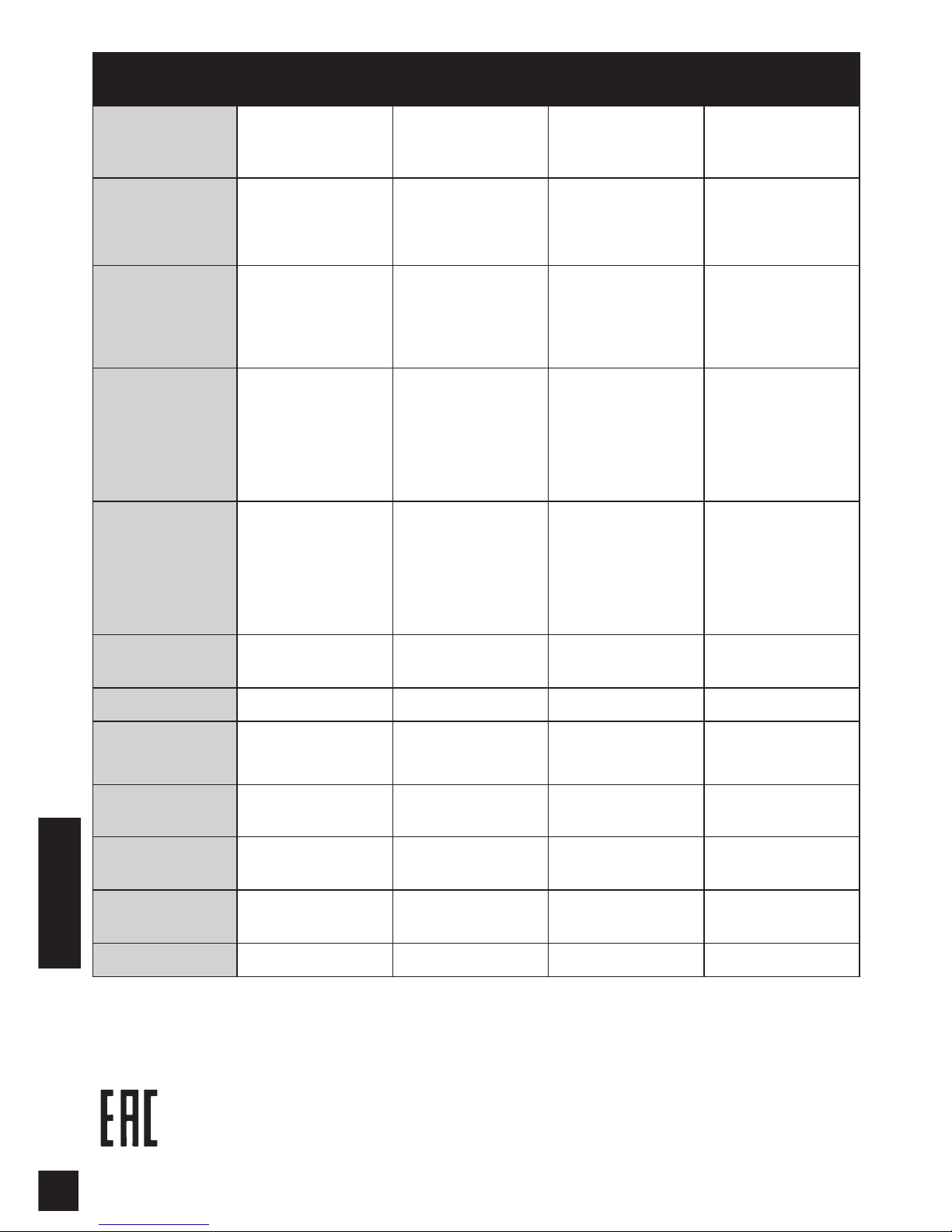
Модель DPS-200A v.A1 DPS-500A v.A1 DPS-500DC v.B1 DPS-700 v.A2
Размеры
172 x 257 x 43 мм
Панель: 196 x
52 мм
172 x 257 x 43 мм
Панель: 196 x
52 мм
172 x 257 x 43 мм
Панель: 196 x
52 мм
441 x 199.4 x
44 мм
Диапазон
входных
напряжений
От 90 В до 264 В
переменного тока
От 90 В до 264 В
переменного тока
От -36 до -72 В
постоянного тока
От 90 до 264 В
переменного
тока
Диапазон
частот входного
сетевого
напряжения
От 47 до 63 Гц От 47 до 63 Гц - От 47 до 63 Гц
Макс. входной
ток
2 A@100 В
переменного тока
1 A@240 В
переменного тока
2 A@100 В
переменного тока
1 A@240 В
переменного тока
6 A@-36 В
постоянного тока
3 A@-72 В
постоянного тока
7,5 A@110 В
переменного
тока
3,7 A@240 В
переменного
тока
Макс. пусковой
ток
30 A@115 В
переменного тока
60 A@230 В
переменного тока
30 A@115 В
переменного тока
60 A@230 В
переменного тока
20 A@-48 В
постоянного тока
30 A@-72 В
постоянного тока
30 A@115 В
переменного
тока
30 A@230 В
переменного
тока
Выходная
мощность
12 В/13 A 12 В/13 A 12 В/12,5 A
12 В/14 A
-54 В/7,8 A
КПД 75% 75% 80% 80%
Рабочая
температура
От 0 до 50 ℃ От 0 до 50 ℃ От 0 до 50 ℃ От 0 до 65 ℃
Температура
хранения
От -45 до 85 ℃ От -45 до 85 ℃ От -40 до 85 ℃ От -40 до 85 ℃
Влажность при
эксплуатации
От 10 до 90% без
конденсата
От 10 до 90% без
конденсата
От 5 до 95% без
конденсата
От 5 до 95% без
конденсата
Влажность при
хранении
От 10 до 95% без
конденсата
От 10 до 95% без
конденсата
От 5 до 95% без
конденсата
От 5 до 95% без
конденсата
MTBF (часы) 400 000 400 000 300 000 624 961
Page 21
2121
中
文
使用手冊說明
D-Link DPS-200A,500A,500DC和700是設計於
放置在機箱的備用電源供應器,以低成本的方式,
提供穩定的電源供應解決方案。此手冊將逐步說明
如何設定DPS-200A、500A、500DC和700與14-pin
或22-pin的DC電源線連接來提供網路交換器供電。
請注意,您所購買的機型可能與手冊中所展示的圖
略有不同。
有關您的交換機的組件如何連接上網路以及技術規
格的更多詳細資訊,請參閱附於此交換器包裝盒的
使用說明書。
介紹
當交換器內建電源供應器故障,導致單一交換器或
整個網路癱瘓時,備用電源供應器具備低成本、簡
易快速的特性,可有效解決交換器內建電源供應器
故障所造成的問題。
在備用電源供應器與交換器連結時,整合式電路偵
測裝置便會持續監控內建電源供應器運作狀態;發
生電源中斷事件時,備用電源供應器便立即被觸發
啟動,讓交換器及介接設備可持續提供服務。
此舉將可提供更高信任度的網路基礎架構,並保
護單一設備因電源供應器故障導致整個網路癱瘓
的窘境。
產品描述
D-Link 設計 DPS-200A、DPS-500A、DPS-500DC及
DPS-700備用電源供應器,可依交換器電源功率需
求選擇符合的備用電源供應器。
DPS-200A、DPS-500A與DPS-500DC使用14-Pin
的DC電源線來連接交換器,DPS-700則是使用的
22-Pin DC電源線。三孔AC電源線為一般標準,可
連接至備援電源供應器的主要電源插座上。
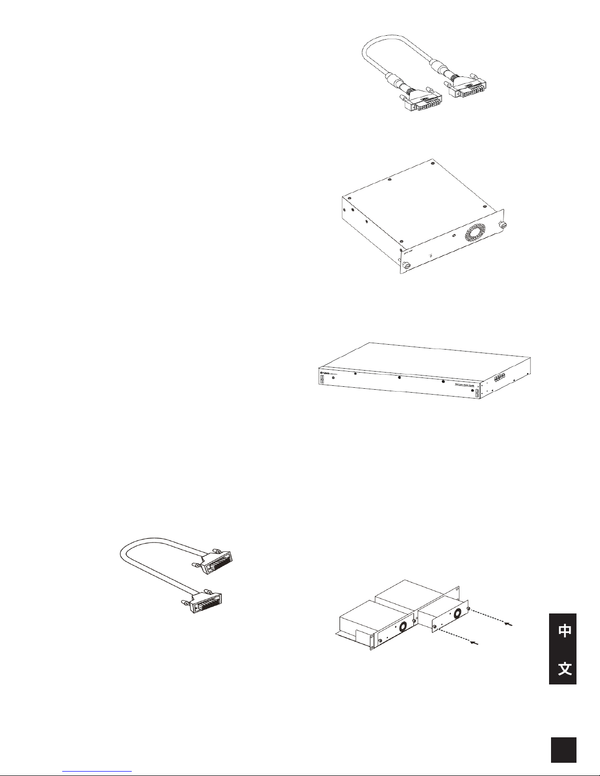
14-pin DC 電源線
22-pin DC 電源線
獨立備援電源供應器
(DPS-200A /DPS-500A/DPS-500DC)
獨立備援電源供應器 (DPS-700)
安裝備用電源供應器
RPS DPS-200A, 500A,及500DC獨立式備用電源供應
器可置入DPS-800標準機架式備用電源專用機箱,
安裝於標準機櫃中。DPS-800(1.25U 高度)可置
入兩個備用電源供應器。可置入 DPS-800的獨立式
備用電源供應器計有DPS-200As, DPS-500As, DPS500DCs,亦可混合置入上述三款備用電源供應器。
將獨立式備用電源供應器置入DPS-800備用電源供應
器專用機箱
Page 22
22
中
文
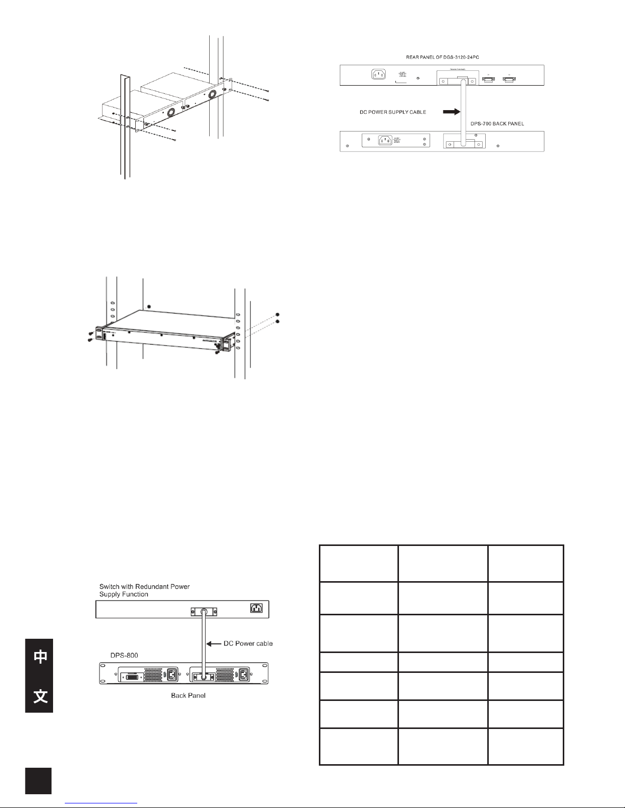
將 DPS-800 安裝於標準機櫃中
DPS-700可以直接安裝於標準積架上,無須搭配
DPS-800。
將 DPS-700 安裝於標準機櫃中
交換器的連接
注意:備用電源供應器未連接至交換器前,請勿
將備用電源供應器電源線插入電源插座。交換器
若直接連結已過電之備用電源供應器可能導致交
換器內建電源供應器損壞。
將直流電源線的一端插入交換機的電源插座,另一端
插入備援電源供應器。
將置於 DPS-800 機箱內的獨立式備用電源供應器連
結至交換器。
連接DPS-700到一台交換器。
注意:不用使用14-Pin DC電源線來連接DPS-700與交
換器。假如使用14-Pin DC電源線來取代正確的22-Pin
DC電源線,可能導致設備的損壞。
電源連接
連接交流電源(DPS-200A/500A/700)
以標準 AC 電源連接線連接至 AC 電源插座,在DPS200A/DPS-500A/DPS-700 前面板 LED 狀態顯示燈號
為綠色,即表示連結成功。
連結 DC 電源(DPS-500DC)
1. 確實將 DC 電源線連接至備用電源供應器集線裝
置正負極。
•負極(-)連接至-48V 接頭。
•正極(+)連接至-48V RTN 接頭。
•建議將接地線連結在集線裝置中間接頭。
2. 鎖緊連結螺絲,確保連接無誤。
連結備用電源供應器,交換器無須更動任何設定。
產品規格
型號 DPS-200A DPS-500A
輸入電壓 100 to 240 V AC
100 to 240V
AC
輸入頻率 50-60 Hz 50-60 Hz
輸入電流 2 А 2 А
輸出電壓 12 V 12 V
輸出電流 13 А 13 А
操作溫度 0 to 50°C 0 to 50°C
Page 23
2323
中
文
型號 DPS-500DC DPS-700
輸入電壓
-36 to
72 V DC
90 to 264
V AC
輸入頻率 - 47-63 Hz
輸入電流 6 А 7.5 A
輸出電壓 12 V 12 V / -54 V
輸出電流 12.5 А 14 A / 7.8 A
操作溫度 0 to 50°C 0 to 65°C
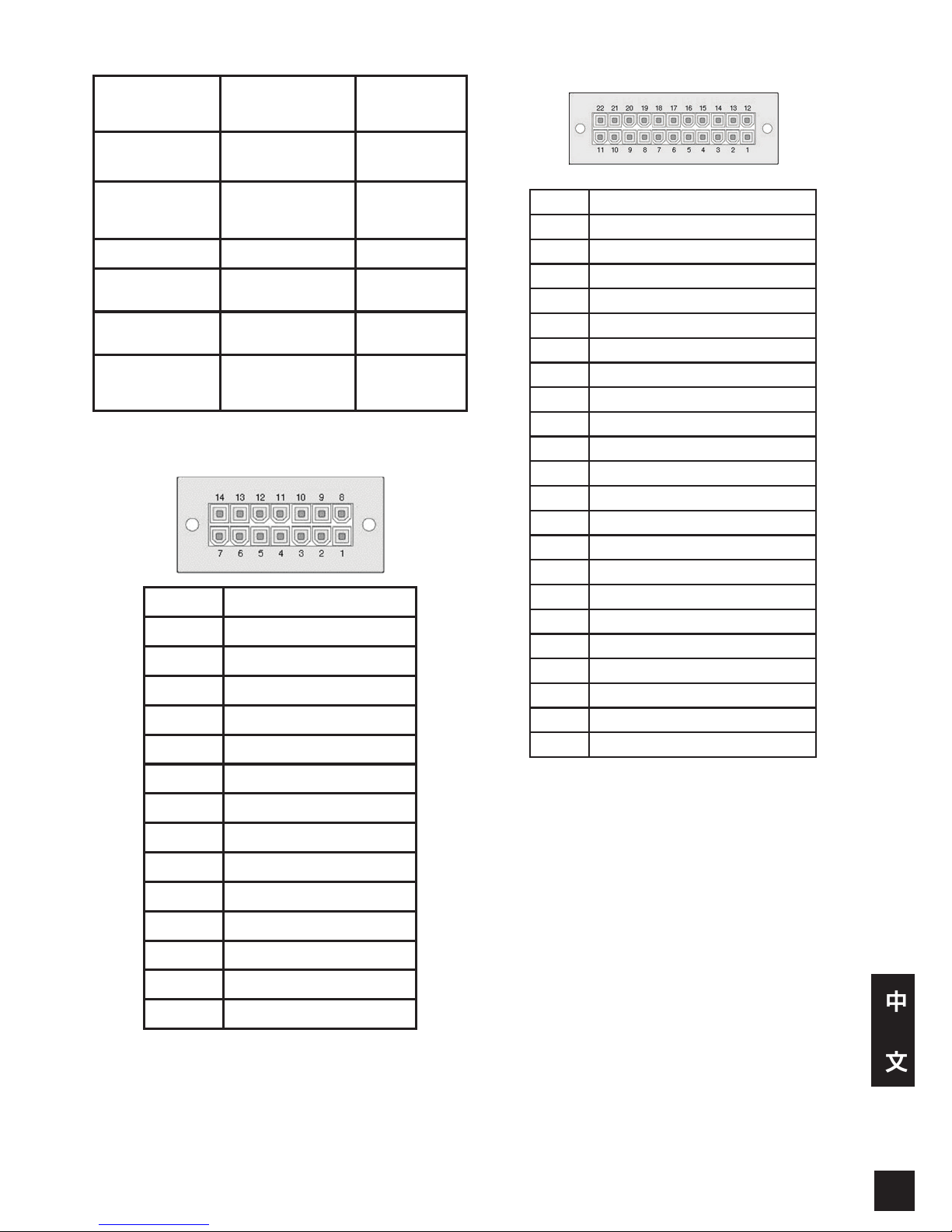
輸出端腳位(DPS-200A/500A/500DCA)
Pin DPS-200A/500A/500DC
1 GND
2 N/C
3 +12 V
4 +12 V
5 +12 V
6 +12 V
7 GND
8 N/C
9 N/C
10 RPS Present
11 N/C
12 N/C
13 PWR-Good
14 GND
輸出端腳位 (DPS-700)
Pin DPS-700
1 -54Vrtn
2 -54V
3 +12 V
4 +12 V
5 +12 V
6 +12 V
7 GND
8 +12VRTNsen
9 LS-54V
10 -54V
11 -54Vrtn
12 GND
13 N/C
14 RPS_Present
15 Status 1
16 Status 2
17 RPS_ Power Good
18 GND
19 +12VRTNsen
20 LS+12V
21 -54Vsen
22 -54VRTNsen
更多資訊
透過聯繫列於使用者手冊背面或D-Link網站上的
D-Link辦公室,您可得到更多的協助資訊。若您要
了解更多關於D-Link產品或銷售資訊,請拜訪D-Link
網站 http://www.dlink.com。
保固資訊
您可於如下網站參閱D-Link產品保固資訊
http://warranty.dlink.com/
Page 24

FCC Warning
This equipment has been tested and found to comply with the limits
for a Class A digital device, pursuant to Part 15 of the FCC Rules.
These limits are designed to provide reasonable protection against
harmful interference when the equipment is operated in a commercial
environment. This equipment generates, uses, and can radiate radio
frequency energy and, if not installed and used in accordance with
this manual, may cause harmful interference to radio communications.
Operation of this equipment in a residential area is likely to cause
harmful interference in which case the user will be required to correct
the interference at his own expense.
CE Mark Warning
This is a Class A product. In a domestic environment, this product may
cause radio interference in which case the user may be required to
take adequate measures.
Warnung!
Dies ist ein Produkt der Klasse A. Im Wohnbereich kann dieses
Produkt Funkstoerungen verursachen. In diesem Fall kann vom
Benutzer verlangt werden, angemessene Massnahmen zu ergreifen.
Precaución!
Este es un producto de Clase A. En un entorno doméstico, puede
causar interferencias de radio, en cuyo case, puede requerirse al
usuario para que adopte las medidas adecuadas.
Attention!
Ceci est un produit de classe A. Dans un environnement domestique,
ce produit pourrait causer des interférences radio, auquel cas
l`utilisateur devrait prendre les mesures adéquates.
Attenzione!
Il presente prodotto appartiene alla classe A. Se utilizzato in ambiente
domestico il prodotto può causare interferenze radio, nel cui caso è
possibile che l`utente debba assumere provvedimenti adeguati.
VCCI Warning
この装置は、クラスA情報技術装置です。この装置を家庭環境で使用す
ると電波妨害を引き起こすことがあります。この場合には使用者が適
切な 対策を講ずるよう要求されることがあります。VCCI-A
警告使用者:
這是甲類的資訊產品,在居住的環境中使用時,可能會造成射頻干擾,
在這種情況下,使用者會被要求採取某些適當的對策。
Warranty Information
The D-Link Limited Lifetime Warranty information is available at http://
warranty.dlink.com/
SAFETY INSTRUCTIONS
Please adhere to the following safety guidelines to help ensure your
own personal safety and protect your system from potential damage.
Any acts taken that are inconsistent with ordinary use of the product,
including improper testing, etc., and those not expressly approved by
D-Link may result in the loss of product warranty.
Unless expressly approved by an authorized representative of D-Link
in writing, you may not and may not permit others to:
• Disassemble or reverse engineer the device or attempt to derive
source code (underlying ideas, algorithms, or structure) from the
device or from any other information provided by
D-Link, except to the extent that this restriction is expressly
prohibited by local law.
• Modify or alter the device.
• Remove from the device any product identification or other
notices, including copyright notices and patent markings, if any.
To reduce the risk of bodily injury, electrical shock, re, and damage to
the device and other equipment, observe the following precautions:
Power Sources
• Observe and follow service markings.
• Do not push any objects into the openings of your device unless
consistent with the authorized operation of the device. Doing so
can cause a re or an electrical shock by shorting out interior
components.
• The powering of this device must adhere to the power
specications indicated for this product.
• Do not overload wall outlets and/or extension cords as this will
increase the risk of re or electrical shock.
• Do not rest anything on the power cord or on the device (unless
the device is made and expressly approved as suitable for
stacking).
• Position system cables and power cables carefully; route cables
so that they cannot be stepped on or tripped over. Be sure that
nothing rests on any cables.
• Operate the device only from the type of external power source
indicated on the electrical ratings label.
• To help avoid damaging your device, be sure the voltage
selection switch (if provided) on the power supply is set to
match the power available at your location.
• Also be sure that attached devices are electrically rated to
operate with the power available in your location.
• Use only approved power cable(s). If you have not been
provided a power cable for your device or for any AC-powered
option intended for your device, purchase a power cable that
is approved for use in your country and is suitable for use with
your device. The power cable must be rated for the device and
for the voltage and current marked on the device’s electrical
ratings label. The voltage and current rating of the cable should
be greater than the ratings marked on the device.
• To help prevent an electrical shock, plug the device and
peripheral power cables into properly grounded electrical
outlets. These cables are equipped with three-prong plugs to
help ensure proper grounding. Do not use adapter plugs or
remove the grounding prong from a cable. If you must use an
extension cable, use a 3-wire cable with properly grounded
plugs.
• Observe extension cable and power strip ratings. Ensure that
the total ampere rating of all products plugged into the extension
cable or power strip does not exceed 80 percent of the ampere
ratings limit for the extension cable or power strip.
• To help protect your device from sudden, transient increases
and decreases in electrical power, use a surge suppressor, line
conditioner, or uninterruptible power supply (UPS).
• Do not modify power cables or plugs. Consult a licensed
electrician or your power company for site modications. Always
follow your local/national wiring rules.
• When connecting or disconnecting power to hot-pluggable
power supplies, if offered with your device, observe the following
guidelines:
• Install the power supply before connecting the power cable to
the power supply.
• Unplug the power cable before removing the power supply.
• If the system has multiple sources of power, disconnect power
from the device by unplugging all power cables from the power
supplies.
僅適用于海拔2000米以下地區安全使用
Page 25

25
Servicing/Disassembling
• Do not service any product except as expressly set forth in your
system documentation.
• Opening or removing covers that are marked with the triangular
symbol with a lightning bolt may expose you to an electrical
shock. Only a trained service technician should service
components inside these compartments.
• To reduce the risk of electrical shock, never disassemble this
device. None of its internal parts are user-replaceable; therefore,
there is no reason to access the interior.
• Do not spill food or liquids on your system components, and
never operate the device in a wet environment. If the device gets
wet, see the appropriate section in your troubleshooting guide or
contact your trained service provider.
• Use the device only with approved equipment.
• Move products with care; ensure that all casters and/or
stabilizers are firmly connected to the system. Avoid sudden
stops and uneven surfaces.
Environment
• Do not use this device near water (e.g. near a bathtub, sink,
laundry tub, sh tank, in a wet basement or near a swimming
pool).
• Do not use this device in areas with high humidity.
• This device must not be subjected to water or condensation.
• Keep your device away from radiators and heat sources. Also,
do not block cooling vents.
Cleaning
• Always unplug the power before cleaning this device.
• Do not use liquid or aerosol cleaners of any kind. Use only
compressed air that is recommended for electronic devices.
• Use a dry cloth for cleaning.
PROTECTING AGAINST ELECTROSTATIC
DISCHARGE
Static electricity can harm delicate components inside your system.
To prevent static damage, discharge static electricity from your body
before you touch any of the electronic components, such as the
microprocessor. You can do so by periodically touching an unpainted
metal surface on the chassis.
You can also take the following steps to help prevent damage from
electrostatic discharge (ESD):
1. When unpacking a static-sensitive component from its shipping
carton, do not remove the component from the antistatic packing
material until you are ready to install the component in your
system. Just before unwrapping the antistatic packaging, be
sure to discharge static electricity from your body.
2. When transporting a sensitive component, first place it in an
antistatic container or packaging.
3. Handle all sensitive components in a static-safe area. If possible,
use antistatic floor pads, workbench pads, and an antistatic
grounding str
INSTRUCCIONES DE SEGURIDAD
Por favor siga las siguientes instrucciones de seguridad para garantizar
su propia seguridad personal y proteger el equipo de posibles daños.
Cualquier acto realizado que sea incompatible con el uso normal del
producto, incluyendo pruebas no apropiadas, etc., y aquellos que no estén
expresamente autorizados por D-Link pueden dar lugar a la pérdida de la
garantía del producto.
A menos que estén expresamente aprobados por escrito por un
representante autorizado de D-Link, usted no puede no puede:
• Desmontar o alterar el diseño del dispositivo o intentar obtener
el código fuente (ideas subyacentes, algoritmos, o estructura del
mismo) del dispositivo o de cualquier otra información proporcionada
por D-Link, salvo en el caso en que esta restricción esté
expresamente prohibida por la ley local.
• Modicar o alterar el dispositivo.
• Retirar la identificación del producto u otras notificaciones,
incluyendo las noticaciones de copyright y marcado de patente, si
fuera el caso.
Para reducir el riesgo de lesiones personales, descargas eléctricas,
incendios y daños al aparato y otro equipamiento, tome las siguientes
precauciones:
Fuentes de alimentación
• Lea y siga atentamente las instrucciones de uso.
• No introduzca ningún objeto en las aberturas de su dispositivo. Si lo
hace, puede provocar un incendio o recibir una descarga eléctrica
debido a un cortocircuito de los componentes internos.
• El suministro eléctrico debe cumplir con las especicaciones de
alimentación indicadas para este producto.
• No sobrecargue los enchufes de pared y / o cables de extensión ya
que esto aumentará el riesgo de producir un incendio o recibir una
descarga eléctrica.
• No apoye nada sobre el cable de alimentación o encima
el dispositivo (a menos que el dispositivo esté diseñado y
expresamente aprobado para ello).
• Coloque los cables del equipo y de la fuente de alimentación con
cuidado, de forma que no se puedan pisar o tropezar fácilmente con
ellos. Asegúrese de que no apoya nada sobre los cables.
• Utilice el dispositivo sólo con una fuente de alimentación externa que
cumpla con las especicaciones eléctricas de la etiqueta.
• Para ayudar a evitar daños en el dispositivo, asegúrese de que
el selector de voltaje (si existe) de la fuente de alimentación está
ajustado para la tensión disponible en su localidad.
• Asegúrese también de que los dispositivos conectados estén
clasicados eléctricamente para funcionar con la tensión disponible
en su ubicación.
• Utilice únicamente cables de alimentación aprobados. Si el equipo
no viniera con cable de alimentación o con cualquier otra opción de
alimentación para corriente alterna, compre un cable de alimentación
que esté aprobado para uso en su país y sea adecuado para
su uso con el dispositivo. El cable de alimentación debe estar
aprobado para el dispositivo y para el voltaje/corriente marcado en
la etiqueta de especicaciones eléctricas que incluye el dispositivo,
debiendo ser el valor de voltaje/corriente del cable superior al de las
especicaciones.
• Para ayudar a prevenir una descarga eléctrica, conecte el dispositivo
en enchufes que dispongan de su correspondiente toma de tierra.
Los cables están equipados con enchufes de tres clavijas para
garantizar una conexión a tierra adecuada. No utilice adaptadores ni
retire la clavija de conexión a tierra de un cable. Si tiene que utilizar
un cable de extensión, utilice un cable de 3 hilos con enchufes
adecuadamente conectados a tierra.
• Asegúrese de que el amperaje total de todos los productos
conectados al cable de extensión o regleta de alimentación no sea
superior al 80 por ciento del amperaje límite del cable de extensión o
de la regleta.
• Para ayudar a proteger el dispositivo de cambios repentinos,
transitorios o disminuciones de la señal eléctrica, utilice un supresor
de sobretensiones, un acondicionador de línea, o una fuente de
alimentación ininterrumpida (SAI).
• No modique los cables de alimentación o los enchufes. Consulte a
un electricista autorizado o con la compañía eléctrica para realizar
las modificaciones necesarias. Siga siempre la normativa de
cableado local/nacional.
• Al conectar o desconectar la alimentación de las fuentes de
alimentación conectables en caliente, si fuera el caso de su
dispositivo, siga las siguientes pautas:
Page 26

EUROPEAN COMMUNITY
DECLARATION OF CONFORMITY
This equipment complies with the essential requirements and other
provisions of Directives 2004/108/EC and 2006/95/EC. For more
information, please refer to the Declaration of Conformity.
WARNING STATEMENT
The power outlet should be nearby the device and easily accessible.
• Instale la fuente de alimentación antes de proporcionar alimentación
a la misma.
• Desconecte la alimentación antes de retirar el cable de alimentación.
• Si el sistema tiene múltiples fuentes de alimentación, desconecte
la alimentación del mismo, y desenchufe todos los cables de
alimentación de las fuentes de alimentación.
• En el caso de que la fuente de alimentación sea el dispositivo de
desconexión del equipo. La base de toma de corriente debe estar
cerca del equipo y ser fácilmente accesible.
Manipulación/ Desmontaje
• No manipule el producto, salvo que esté expresamente establecido
en la documentación del equipo.
• Si abre o retira las cubiertas que están marcadas con el símbolo
triangular con un rayo puede exponerse a una descarga eléctrica.
Sólo un técnico cualicado debe reparar los componentes dentro de
estos compartimientos.
• Para reducir el riesgo de descarga eléctrica, no desmonte el
dispositivo. Ninguno de sus partes internas es sustituible por el
usuario, por lo tanto, no hay ninguna razón para acceder al interior.
• No derrame comida ni líquidos sobre los componentes del sistema,
y nunca utilice el dispositivo en un ambiente húmedo. Si el
dispositivo se moja, consulte la sección correspondiente a solución
de problemas o contacte con su proveedor.
• Utilice el dispositivo sólo con equipamiento aprobado.
• Mueva los productos con cuidado; asegúrese de que todos los
estabilizadores están firmemente sujetos al equipo. Evite las
detenciones repentinas y las supercies irregulares.
Medio Ambiente
• No utilice este aparato cerca del agua (por ejemplo, cerca de una
bañera, fregadero, lavadero, peceras, en un sótano húmedo o cerca
de una piscina).
• No utilice este dispositivo en lugares con alta humedad.
• Este dispositivo no debe ser sometido al agua o la condensación.
• Mantenga el dispositivo alejado de radiadores y fuentes de calor.
Asimismo, no bloquee las rejillas de ventilación.
Limpieza
• Desconecte siempre la alimentación antes de limpiar este
dispositivo.
• No utilice limpiadores en aerosol o líquidos de ningún tipo. Use sólo
aire comprimido recomendado para dispositivos electrónicos.
• Utilice un paño seco para limpiarlo.
PROTECCIÓN CONTRA DESCARGAS
ELECTROSTÁTICAS
La electricidad estática puede dañar componentes delicados de su
sistema. Para evitar daños por electricidad estática, descargar la
electricidad estática de su cuerpo antes de tocar cualquiera de los
componentes electrónicos, tales como el microprocesador. Puede
hacerlo con un toque periódicamente de una supercie metálica sin
pintura del propio chasis del equipo.
También puede realizar los siguientes pasos para ayudar a prevenir
posibles daños por descargas electrostáticas:
1. Al desembalar un componente sensible a la electricidad
estática de su caja de envío, no retire el material de embalaje
antiestático hasta que esté listo para instalar el componente
en su sistema. Justo antes de abrir el embalaje antiestático,
asegúrese de descargar la electricidad estática de su cuerpo.
2. Cuando transporte un componente sensible a la electricidad
estática, colóquelo en un contenedor o embalaje antiestático.
3. Maneje todos los componentes sensibles a la electricidad
estática en un área de prueba libre de cargas electrostáticas. Si
es posible, utilice alfombrillas antiestáticas en el suelo, el banco
de trabajo, y una correa antiestática con conexión a tierra.
Page 27
27
DISPOSING AND RECYCLING
YOUR PRODUCT
ENGLISH
EN
This symbol on the product or packaging means that according
to local laws and regulations this product should be not be
disposed of in the household waste but sent for recycling.
Please take it to a collection point designated by your local
authorities once it has reached the end of its life, some will
accept products for free. By recycling the product and its
packaging in this manner you help to conserve the environment
and protect human health.
D-Link and the environment
At D-Link, we understand and are committed to reducing
any impact our operations and products may have on the
environment. To minimise this impact D-Link designs and
builds its products to be as environmentally friendly as possible,
by using recyclable, low toxic materials in both products and
packaging.
D-Link recommends that you always switch off or unplug your
D-Link products when they are not in use. By doing so you will
help to save energy and reduce CO2 emissions.
To learn more about our environmentally responsible products
and packaging please visit www.dlinkgreen.com
DEUTSCH
DE
FRANÇAIS
FR
Dieses Symbol auf dem Produkt oder der Verpackung weist darauf
hin, dass dieses Produkt gemäß bestehender örtlicher Gesetze und
Vorschriften nicht über den normalen Hausmüll entsorgt werden
sollte, sondern einer Wiederverwertung zuzuführen ist. Bringen
Sie es bitte zu einer von Ihrer Kommunalbehörde entsprechend
amtlich ausgewiesenen Sammelstelle, sobald das Produkt das
Ende seiner Nutzungsdauer erreicht hat. Für die Annahme solcher
Produkte erheben einige dieser Stellen keine Gebühren. Durch ein
auf diese Weise durchgeführtes Recycling des Produkts und seiner
Verpackung helfen Sie, die Umwelt zu schonen und die menschliche
Gesundheit zu schützen.
D-Link und die Umwelt
D-Link ist sich den möglichen Auswirkungen seiner
Geschäftstätigkeiten und seiner Produkte auf die Umwelt
bewusst und fühlt sich verpflichtet, diese entsprechend zu
mindern. Zu diesem Zweck entwickelt und stellt D-Link seine
Produkte mit dem Ziel größtmöglicher Umweltfreundlichkeit her
und verwendet wiederverwertbare, schadstoffarme Materialien
bei Produktherstellung und Verpackung.
D-Link empehlt, Ihre Produkte von D-Link, wenn nicht in Gebrauch,
immer auszuschalten oder vom Netz zu nehmen. Auf diese Weise
helfen Sie, Energie zu sparen und CO2-Emissionen zu reduzieren.
Wenn Sie mehr über unsere umweltgerechten Produkte und
Verpackungen wissen möchten, finden Sie entsprechende
Informationen im Internet unter www.dlinkgreen.com.
Ce symbole apposé sur le produit ou son emballage signie que,
conformément aux lois et règlementations locales, ce produit ne
doit pas être éliminé avec les déchets domestiques mais recyclé.
Veuillez le rapporter à un point de collecte prévu à cet effet par les
autorités locales; certains accepteront vos produits gratuitement. En
recyclant le produit et son emballage de cette manière, vous aidez à
préserver l’environnement et à protéger la santé de l’homme.
D-Link et l’environnement
Chez D-Link, nous sommes conscients de l'impact de nos
opérations et produits sur l'environnement et nous engageons à
le réduire. Pour limiter cet impact, D-Link conçoit et fabrique ses
produits de manière aussi écologique que possible, en utilisant
des matériaux recyclables et faiblement toxiques, tant dans ses
produits que ses emballages.
D-Link recommande de toujours éteindre ou débrancher vos
produits D-Link lorsque vous ne les utilisez pas. Vous réaliserez
ainsi des économies d’énergie et réduirez vos émissions de
CO2.
Pour en savoir plus sur les produits et emballages respectueux
de l’environnement, veuillez consulter le www.dlinkgreen.com
ESPAÑOL
ES
ITALIANO
IT
Este símbolo en el producto o el embalaje significa que, de
acuerdo con la legislación y la normativa local, este producto
no se debe desechar en la basura doméstica sino que se debe
reciclar. Llévelo a un punto de recogida designado por las
autoridades locales una vez que ha llegado al fin de su vida
útil; algunos de ellos aceptan recogerlos de forma gratuita. Al
reciclar el producto y su embalaje de esta forma, contribuye a
preservar el medio ambiente y a proteger la salud de los seres
humanos.
D-Link y el medio ambiente
En D-Link, comprendemos y estamos comprometidos con la
reducción del impacto que puedan tener nuestras actividades
y nuestros productos en el medio ambiente. Para reducir este
impacto, D-Link diseña y fabrica sus productos para que sean
lo más ecológicos posible, utilizando materiales reciclables y de
baja toxicidad tanto en los productos como en el embalaje.
D-Link recomienda apagar o desenchufar los productos D-Link
cuando no se estén utilizando. Al hacerlo, contribuirá a ahorrar
energía y a reducir las emisiones de CO2.
Para obtener más información acerca de nuestros productos y
embalajes ecológicos, visite el sitio www.dlinkgreen.com
La presenza di questo simbolo sul prodotto o sulla confezione
del prodotto indica che, in conformità alle leggi e alle normative
locali, questo prodotto non deve essere smaltito nei rifiuti
domestici, ma avviato al riciclo. Una volta terminato il ciclo di
vita utile, portare il prodotto presso un punto di raccolta indicato
dalle autorità locali. Alcuni questi punti di raccolta accettano
gratuitamente i prodotti da riciclare. Scegliendo di riciclare il
prodotto e il relativo imballaggio, si contribuirà a preservare
l'ambiente e a salvaguardare la salute umana.
D-Link e l'ambiente
D-Link cerca da sempre di ridurre l'impatto ambientale dei propri
stabilimenti e dei propri prodotti. Allo scopo di ridurre al minimo
tale impatto, D-Link progetta e realizza i propri prodotti in modo
che rispettino il più possibile l'ambiente, utilizzando materiali
riciclabili a basso tasso di tossicità sia per i prodotti che per gli
imballaggi.
D-Link raccomanda di spegnere sempre i prodotti D-Link o di
scollegarne la spina quando non vengono utilizzati. In questo
modo si contribuirà a risparmiare energia e a ridurre le emissioni
di anidride carbonica.
Per ulteriori informazioni sui prodotti e sugli imballaggi D-Link
a ridotto impatto ambientale, visitate il sito all'indirizzo www.
dlinkgreen.com
NEDERLANDS
NL
Dit symbool op het product of de verpakking betekent dat dit
product volgens de plaatselijke wetgeving niet mag worden
weggegooid met het huishoudelijk afval, maar voor recyclage
moeten worden ingeleverd. Zodra het product het einde van
de levensduur heeft bereikt, dient u het naar een inzamelpunt
te brengen dat hiertoe werd aangeduid door uw plaatselijke
autoriteiten, sommige autoriteiten accepteren producten
zonder dat u hiervoor dient te betalen. Door het product en de
verpakking op deze manier te recyclen helpt u het milieu en de
gezondheid van de mens te beschermen.
D-Link en het milieu
Bij D-Link spannen we ons in om de impact van onze
handelingen en producten op het milieu te beperken. Om deze
impact te beperken, ontwerpt en bouwt D-Link zijn producten zo
milieuvriendelijk mogelijk, door het gebruik van recycleerbare
producten met lage toxiciteit in product en verpakking.
D-Link raadt aan om steeds uw D-Link producten uit te schakelen
of uit de stekker te halen wanneer u ze niet gebruikt. Door dit te
doen bespaart u energie en beperkt u de CO2-emissies.
Breng een bezoek aan www.dlinkgreen.com voor meer informatie
over onze milieuverantwoorde producten en verpakkingen
POLSKI
PL
Č
ESKY
CZ
Ten symbol umieszczony na produkcie lub opakowaniu oznacza,
że zgodnie z miejscowym prawem i lokalnymi przepisami
niniejszego produktu nie wolno wyrzucać jak odpady czy
śmieci z gospodarstwa domowego, lecz należy go poddać
procesowi recyklingu. Po zakończeniu użytkowania produktu,
niektóre odpowiednie do tego celu podmioty przyjmą takie
produkty nieodpłatnie, dlatego prosimy dostarczyć go do punktu
zbiórki wskazanego przez lokalne władze. Poprzez proces
recyklingu i dzięki takiemu postępowaniu z produktem oraz jego
opakowaniem, pomogą Państwo chronić środowisko naturalne i
dbać o ludzkie zdrowie.
D-Link i środowisko
W D-Link podchodzimy w sposób świadomy do ochrony
otoczenia oraz jesteśmy zaangażowani w zmniejszanie
wpływu naszych działań i produktów na środowisko naturalne.
W celu zminimalizowania takiego wpływu firma D-Link
konstruuje i wytwarza swoje produkty w taki sposób, aby były
one jak najbardziej przyjazne środowisku, stosując do tych
celów materiały nadające się do powtórnego wykorzystania,
charakteryzujące się małą toksycznością zarówno w przypadku
samych produktów jak i opakowań.
Firma D-Link zaleca, aby Państwo zawsze prawidłowo wyłączali
z użytku swoje produkty D-Link, gdy nie są one wykorzystywane.
Postępując w ten sposób pozwalają Państwo oszczędzać
energię i zmniejszać emisje CO2.
Aby dowiedzieć się więcej na temat produktów i opakowań
mających wpływ na środowisko prosimy zapoznać się ze stroną
internetową www.dlinkgreen.com.
Tento symbol na výrobku nebo jeho obalu znamená, že podle
místně platných předpisů se výrobek nesmí vyhazovat do
komunálního odpadu, ale odeslat k recyklaci. Až výrobek
doslouží, odneste jej prosím na sběrné místo určené místními
úřady k tomuto účelu. Některá sběrná místa přijímají výrobky
zdarma. Recyklací výrobku i obalu pomáháte chránit životní
prostředí i lidské zdraví.
D-Link a životní prostředí
Ve společnosti D-Link jsme si vědomi vlivu našich provozů a
výrobků na životní prostředí a snažíme se o minimalizaci těchto
vlivů. Proto své výrobky navrhujeme a vyrábíme tak, aby
byly co nejekologičtější, a ve výrobcích i obalech používáme
recyklovatelné a nízkotoxické materiály.
Společnost D-Link doporučuje, abyste své výrobky značky D-Link
vypnuli nebo vytáhli ze zásuvky vždy, když je nepoužíváte.
Pomůžete tak šetřit energii a snížit emise CO2.
Více informací o našich ekologických výrobcích a obalech najdete
na adrese www.dlinkgreen.com.
Page 28
MAGYAR
HU
Ez a szimbólum a terméken vagy a csomagoláson azt jelenti,
hogy a helyi törvényeknek és szabályoknak megfelelően ez a
termék nem semmisíthető meg a háztartási hulladékkal együtt,
hanem újrahasznosításra kell küldeni. Kérjük, hogy a termék
élettartamának elteltét követően vigye azt a helyi hatóság
által kijelölt gyűjtőhelyre. A termékek egyes helyeken ingyen
elhelyezhetők. A termék és a csomagolás újrahasznosításával
segíti védeni a környezetet és az emberek egészségét.
A D-Link és a környezet
A D-Linknél megértjük és elkötelezettek vagyunk a műveleteink
és termékeink környezetre gyakorolt hatásainak csökkentésére.
Az ezen hatás csökkentése érdekében a D-Link a lehető
leginkább környezetbarát termékeket tervez és gyárt azáltal,
hogy újrahasznosítható, alacsony károsanyag-tartalmú
termékeket gyárt és csomagolásokat alkalmaz.
A D-Link azt javasolja, hogy mindig kapcsolja ki vagy húzza ki
a D-Link termékeket a tápforrásból, ha nem használja azokat.
Ezzel segít az energia megtakarításában és a szén-dioxid
kibocsátásának csökkentésében.
Környezetbarát termékeinkről és csomagolásainkról további
információkat a www.dlinkgreen.com weboldalon tudhat meg.
NORSK
NO
DANSK
DK
SUOMI
FI
Dette symbolet på produktet eller forpakningen betyr at dette
produktet ifølge lokale lover og forskrifter ikke skal kastes
sammen med husholdningsavfall, men leveres inn til gjenvinning.
Vennligst ta det til et innsamlingssted anvist av lokale
myndigheter når det er kommet til slutten av levetiden. Noen
steder aksepteres produkter uten avgift. Ved på denne måten å
gjenvinne produktet og forpakningen hjelper du å verne miljøet
og beskytte folks helse.
D-Link og miljøet
Hos D-Link forstår vi oss på og er forpliktet til å minske
innvirkningen som vår drift og våre produkter kan ha på miljøet.
For å minimalisere denne innvirkningen designer og lager
D-Link produkter som er så miljøvennlig som mulig, ved å bruke
resirkulerbare, lav-toksiske materialer både i produktene og
forpakningen.
D-Link anbefaler at du alltid slår av eller frakobler D-Linkprodukter når de ikke er i bruk. Ved å gjøre dette hjelper du å
spare energi og å redusere CO2-utslipp.
For mer informasjon angående våre miljøansvarlige produkter og
forpakninger kan du gå til www.dlinkgreen.com
Dette symbol på produktet eller emballagen betyder, at dette
produkt i henhold til lokale love og regler ikke må bortskaffes
som husholdningsaffald, mens skal sendes til genbrug. Indlever
produktet til et indsamlingssted som angivet af de lokale
myndigheder, når det er nået til slutningen af dets levetid. I nogle
tilfælde vil produktet blive modtaget gratis. Ved at indlevere
produktet og dets emballage til genbrug på denne måde bidrager
du til at beskytte miljøet og den menneskelige sundhed.
D-Link og miljøet
Hos D-Link forstår vi og bestræber os på at reducere enhver
indvirkning, som vores aktiviteter og produkter kan have
på miljøet. For at minimere denne indvirkning designer og
producerer D-Link sine produkter, så de er så miljøvenlige
som muligt, ved at bruge genanvendelige materialer med lavt
giftighedsniveau i både produkter og emballage.
D-Link anbefaler, at du altid slukker eller frakobler dine D-Linkprodukter, når de ikke er i brug. Ved at gøre det bidrager du til at
spare energi og reducere CO2-udledningerne.
Du kan nde ere oplysninger om vores miljømæssigt ansvarlige
produkter og emballage på www.dlinkgreen.com
Tämä symboli tuotteen pakkauksessa tarkoittaa, että paikallisten
lakien ja säännösten mukaisesti tätä tuotetta ei pidä hävittää
yleisen kotitalousjätteen seassa vaan se tulee toimittaa
kierrätettäväksi. Kun tuote on elinkaarensa päässä, toimita se
lähimpään viranomaisten hyväksymään kierrätyspisteeseen.
Kierrättämällä käytetyn tuotteen ja sen pakkauksen autat
tukemaan sekä ympäristön että ihmisten terveyttä ja hyvinvointia.
D-Link ja ympäristö
D-Link ymmärtää ympäristönsuojelun tärkeyden ja on sitoutunut
vähentämään tuotteistaan ja niiden valmistuksesta ympäristölle
mahdollisesti aiheutuvia haittavaikutuksia. Nämä negatiiviset
vaikutukset minimoidakseen D-Link suunnittelee ja valmistaa
tuotteensa mahdollisimman ympäristöystävällisiksi käyttämällä
kierrätettäviä, alhaisia pitoisuuksia haitallisia aineita sisältäviä
materiaaleja sekä tuotteissaan että niiden pakkauksissa.
Suosittelemme, että irrotat D-Link-tuotteesi virtalähteestä tai
sammutat ne aina, kun ne eivät ole käytössä. Toimimalla näin
autat säästämään energiaa ja vähentämään hiilidioksiidipäästöjä.
Lue lisää ympäristöystävällisistä D-Link-tuotteista ja
pakkauksistamme osoitteesta www.dlinkgreen.com
SVENSKA
SE
PORTUGUÊS
PT
Den här symbolen på produkten eller förpackningen betyder
att produkten enligt lokala lagar och föreskrifter inte skall
kastas i hushållssoporna utan i stället återvinnas. Ta den vid
slutet av dess livslängd till en av din lokala myndighet utsedd
uppsamlingsplats, vissa accepterar produkter utan kostnad.
Genom att på detta sätt återvinna produkten och förpackningen
hjälper du till att bevara miljön och skydda människors hälsa.
D-Link och miljön
På D-Link förstår vi och är fast beslutna att minska den påverkan
våra verksamheter och produkter kan ha på miljön. För att
minska denna påverkan utformar och bygger D-Link sina
produkter för att de ska vara så miljövänliga som möjligt, genom
att använda återvinningsbara material med låg gifthalt i både
produkter och förpackningar.
D-Link rekommenderar att du alltid stänger av eller kopplar ur
dina D-Link produkter när du inte använder dem. Genom att
göra detta hjälper du till att spara energi och minska utsläpp av
koldioxid.
För mer information om våra miljöansvariga produkter och
förpackningar www.dlinkgreen.com
Este símbolo no produto ou embalagem signica que, de acordo
com as leis e regulamentações locais, este produto não deverá
ser eliminado juntamente com o lixo doméstico mas enviado
para a reciclagem. Transporte-o para um ponto de recolha
designado pelas suas autoridades locais quando este tiver
atingido o fim da sua vida útil, alguns destes pontos aceitam
produtos gratuitamente. Ao reciclar o produto e respectiva
embalagem desta forma, ajuda a preservar o ambiente e protege
a saúde humana.
A D-Link e o ambiente
Na D-Link compreendemos e comprometemo-nos com a
redução do impacto que as nossas operações e produtos
possam ter no ambiente. Para minimizar este impacto a
D-Link concebe e constrói os seus produtos para que estes
sejam o mais inofensivos para o ambiente possível, utilizando
meteriais recicláveis e não tóxicos tanto nos produtos como nas
embalagens,
A D-Link recomenda que desligue os seus produtos D-Link
quando estes não se encontrarem em utilização. Com esta
acção ajudará a poupar energia e reduzir as emissões de CO2.
Para saber mais sobre os nossos produtos e embalagens
responsáveis a nível ambiental visite www.dlinkgreen.com
PYCCКИЙ
RU
Этот символ на продукте или упаковке означает, что в
соответствии с нормами местного законодательства данный
продукт в случае выхода из строя подлежит утилизации, и
от него нельзя избавиться как от обычного бытового мусора.
Отнесите устройство в ближайшую службу утилизации и
переработки. При утилизации продукта и его упаковки таким
образом обеспечивается защита окружающей среды и не
наносится вред здоровью людей.
Забота D-Link об окружающей среде
Компания D-Link стремится максимально сократить негативное
влияние своей деятельности на окружающую среду. Поэтому
D-Link разрабатывает максимально экологичные продукты,
используя легкоперерабатываемые и низкотоксичные
материалы как для изготовления самих продуктов, так и их
упаковки.
Кроме того, D-Link рекомендует отключать устройства, если они
не используются. Это обеспечит энергосбережение и сократит
выброс в атмосферу углекислого газа.
Более подробная информация об экологичной продукции D-Link
доступна на сайте www.dlinkgreen.com
Page 29

29
NOTES
Page 30

NOTES
Page 31

31
NOTES
Page 32

Ver.1.10(DI)_130x183 2015/01/15 10-0003-0002
 Loading...