

Page 1

ISDN TERMINAL ADAPTER (TA)
DMI-128ESU+
User’s Guide
Rev.01 (February, 2004)
LIMITED WARRANTY
D-LINK ISDN TA DMI-128ESU+
1
Page 2

LIMITED WARRANTY
D-Link Corp. (“D-Link”) provides this limited warranty for its product only to the person or
entity who originally purchased the product from D-Link or its authorized reseller or distributor.
Limited Hardware Warranty:
D-Link warrants that the hardware portion of the D-Link
products described below (“Hardware”) will be free from material defects in workmanship and
materials from the date of original retail purchase of the Hardware, for the period set forth
below applicable to the product type (“Warranty Period”) if the Hardware is used and serviced
in accordance with applicable documentation; provided that a completed Registration Card is
returned to an Authorized D-Link Service Office within ninety (90) days after the date of
original retail purchase of the Hardware. If a completed Registration Card is not received by an
authorized D-Link Service Office within such ninety (90) periods, then the Warranty Period
shall be ninety (90) days from the date of purchase.
Product Type Warranty
Period
Product (excluding power supplies
and fans), if purchased and
delivered in the fifty (50) United
States, or the District of Columbia
As long as the
original purchaser
still owns the
product
(“USA”)
Product purchased or delivered
outside the USA
One (1) Year
Power Supplies and Fans One (1) Year
Power Adapter Ninety (90) days
Spare parts and spare kits
Ninety (90) days
D-Link’s sole obligation shall be to repair or replace the defective Hardware at no charge to the
original owner. Such repair or replacement will be rendered by D-Link at an Authorized D-Link
Service Office. The replacement Hardware need not be new or of an identical make, model or
part; D-Link may in its discretion may replace the defective Hardware (or any part thereof) with
any reconditioned product that D-Link reasonably determines is substantially equivalent (or
superior) in all material respects to the defective Hardware. The Warranty Period shall extend
for an additional ninety (90) days after any repaired or replaced Hardware is delivered. If a
material defect is incapable of correction, or if D-Link determines in its sole discretion that it is
not practical to repair or replace the defective Hardware, the price paid by the original purchaser
for the defective Hardware will be refunded by D-Link upon return to D-Link of the defective
Hardware. All Hardware (or part thereof) that is replaced by D-Link, or for which the purchase
price is refunded, shall become the property of D-Link upon replacement or refund.
Limited Software Warranty
: D-Link warrants that the software portion of the product
(“Software”) will substantially conform to D-Link’s then current functional specifications for the
Software, as set forth in the applicable documentation, from the date of original delivery of the
Software for a period of ninety (90) days (“Warranty Period”), if the Software is properly
installed on approved hardware and operated as contemplated in its documentation. D-Link
further warrants that, during the Warranty Period, the magnetic media on which D-Link delivers
D-LINK ISDN TA DMI-128ESU+
2
Page 3

the Software will be free of physical defects. D-Link’s sole obligation shall be to replace the
non-conforming Software (or defective media) with software that substantially conforms to
D-Link’s functional specifications for the Software. Except as otherwise agreed by D-Link in
writing, the replacement Software is provided only to the original licensee, and is subject to the
terms and conditions of the license granted by D-Link for the Software. The Warranty Period
shall
extend for an additional ninety (90) days after any replacement Software is delivered. If a
material non-conformance is incapable of correction, or if D-Link determines in its sole
discretion that it is not practical to replace the non-conforming Software, the price paid by the
original licensee for the non-conforming Software will be refunded by D-Link; provided that the
non-conforming Software (and all copies thereof) is first returned to D-Link. The license granted
respecting any Software for which a refund is given automatically terminates.
What You Must Do For Warranty Service:
Registration Card
. The Registration Card provided at the back of this manual must be
completed and returned to an Authorized D-Link Service Office for each D-Link product within
ninety (90) days after the product is purchased and/or licensed. The addresses/telephone/fax list
of the nearest Authorized D-Link Service Office is provided in the back of this manual.
FAILURE TO PROPERLY COMPLETE AND TIMELY RETURN THE REGISTRATION
CARD MAY AFFECT THE WARRANTY FOR THIS PRODUCT.
Submitting A Claim
. Any claim under this limited warranty must be submitted in writing
before the end of the Warranty Period to an Authorized D-Link Service Office. The claim must
include a written description of the Hardware defect or Software nonconformance in sufficient
detail to allow D-Link to confirm the same. The original product owner must obtain a Return
Material Authorization (RMA) number from the Authorized D-Link Service Office and, if
requested, provide written proof of purchase of the product (such as a copy of the dated purchase
invoice for the product) before the warranty service is provided. After an RMA number is
issued, the defective product must be packaged securely in the original or other suitable shipping
package to ensure that it will not be damaged in transit, and the RMA number must be
prominently marked on the outside of the package. The foregoing requirements, or for which an
RMA number is not visible from the outside of the package. The product owner agrees to pay D-
Link’s reasonable handling and return shipping charges for any product that is not packaged and
shipped in accordance with the foregoing requirements, or that is determined by D-Link not to be
defective or non-conforming.
What Is Not Covered:
This limited warranty provided by D-Link does not cover
Products that have been subjected to abuse, accident, alteration, modification, tampering,
negligence, misuse, faulty installation, lack of reasonable care, repair or service in any way that
is not contemplated in the documentation for the product, or if the model or serial number has
been altered, tampered with, defaced or removed;
Initial installation, installation and removal of the product for repair, and shipping costs;
Operational adjustments covered in the operating manual for the product, and normal
D-LINK ISDN TA DMI-128ESU+
:
3
Page 4

maintenance; Damage that occurs in shipment, due to act of God, failures due to power surge,
lightning and telephone line surges and cosmetic damage; and Any hardware, software, firmware
or other products or services provided by anyone other than D-Link
Disclaimer of Other Warranties
EXCEPT FOR THE LIMITED WARRANTY
:
.
SPECIFIED HEREIN, THE PRODUCT IS PROVIDED “AS-IS” WITHOUT ANY
WARRANTY OF ANY KIND INCLUDING, WITHOUT LIMITATION, ANY
WARRANTY OF MERCHANTABILITY, FITNESS FOR A PARTICULAR PURPOSE
AND NON-INFRINGEMENT. IF ANY IMPLIED WARRANTY CANNOT BE
DISCLAIMED IN ANY TERRITORY WHERE A PRODUCT IS SOLD, THE
DURATION OF SUCH IMPLIED WARRANTY SHALL BE LIMITED TO NINETY
(90) DAYS. EXCEPT AS EXPRESSLY COVERED UNDER THE LIMITED
WARRANTY PROVIDED HEREIN, THE ENTIRE RISK AS TO THE QUALITY,
SELECTION AND PERFORMANCE OF THE PRODUCT IS WITH THE
PURCHASER OF THE PRODUCT
Limitation of Liability
TO THE MAXIMUM EXTENT PERMITTED BY LAW, D-
:
.
LINK IS NOT LIABLE UNDER ANY CONTRACT, NEGLIGENCE, STRICT
LIABILITY OR OTHER LEGAL OR EQUITABLE THEORY FOR ANY LOSS OF USE
OF THE PRODUCT, INCONVENIENCE OR DAMAGES OF ANY CHARACTER,
WHETHER DIRECT, SPECIAL, INCIDENTAL OR CONSEQUENTIAL (INCLUDING,
BUT NOT LIMITED TO, DAMAGES FOR LOSS OF GOODWILL, WORK
STOPPAGE, COMPUTER FAILURE OR MALFUNCTION, LOSS OF
INFORMATION OR DATA CONTAINED IN, STORED ON, OR INTEGRATED
WITH ANY PRODUCT RETURNED TO D-LINK FOR WARRANTY SERVICE)
RESULTING FROM THE USE OF THE PRODUCT, RELATING TO WARRANTY
SERVICE, OR ARISING OUT OF ANY BREACH OF THIS LIMITED WARRANTY,
EVEN IF D-LINK HAS BEEN ADVISED OF THE POSSIBILITY OF SUCH
DAMAGES. THE SOLE REMEDY FOR A BREACH OF THE FOREGOING
LIMITED WARRANTY IS REPAIR, REPLACEMENT OR REFUND OF THE
DEFECTIVE OR NON-CONFORMING PRODUCT
.
This Limited Warranty shall be governed by the laws of the state of California. Some states
GOVERNING LAW
do not allow exclusion or limitation of incidental or consequential damages, or limitations on how long an implied
warranty lasts, so the foregoing limitations and exclusions may not apply. This limited warranty provides specific
legal rights and the product owner may also have other rights which vary from state to state.
Trademarks
:
Copyright 1999 D-Link Corporation. Contents subject to change without prior notice. D-
Link is a registered trademark of D-Link Corporation/D-Link Systems, Inc. All other
trademarks belong to their respective proprietors.
D-LINK ISDN TA DMI-128ESU+
4
Page 5

Copyright Statement
No part of this publication may be reproduced in any form or by any means or used to make any
derivative such as translation, transformation, or adaptation without permission from D-Link
Corporation/D-Link Systems Inc., as stipulated by the United States Copyright Act of 1976.
D-LINK ISDN TA DMI-128ESU+
5
Page 6

TABLE OF CONTENTS
1. Introduction ........................................................................................................................8
2. Features
.............................................................................................................................9
3. Outlet Description ............................................................................................................10
3.1 F
RONT PANEL
3.2 R
EAR PANEL CONNECTION
3.3 S
IDE PANEL
....................................................................................................................................................................................10
.................................................................................................................................................................11
........................................................................................................................................................................................11
4 Connection Method...........................................................................................................12
4.1 C
ONNECTION PROCEDURES
4.2 C
ONNECTION WITH TELEPHONE/FAX
ONNECTION WITH
4.3 C
4.4 C
ONNECTION WITH MODEM
ULTI-DROP CONNECTION
4.5 M
4.6 C
ONNECTION NOTIFICATION
...............................................................................................................................................................12
................................................................................................................................................12
PC ......................................................................................................................................................................12
................................................................................................................................................................13
..............................................................................................................................................................13
...............................................................................................................................................................13
5 Installing The TA...............................................................................................................14
5.1 P
ACKING LIST
5.2 W
HAT ELSE YOU NEED
NSTALLING THE
5.3 I
5.4 T
IPS ON CONFIGURING WINDOWS
5.5 Windows 98/2000 and USB.........................................................................................................................................................17
5.5.1 Linux operating systems with RS 232.......................................................................................................................................18
5.5.2 USB installation Procedure ……………………………………………………………………………19
5.5.4 Tips on configuring your Dial Up Network …………………………………………………………25
5.6 V
ERIFYING YOUR CONNECTION
....................................................................................................................................................................................14
...................................................................................................................................................................... 15
TA............................................................................................................................................................................15
98/NT/2000...................................................................................................................................15
..........................................................................................................................................................27
6. AT COMMAND
ESCRIPTION OF
6.1 D
6.1.1 AT Command ..........................................................................................................................................................................28
6.2 AT C
OMMAND
6.2.1 AT Command Overview .........................................................................................................................................................29
6.2.2 AT Command List ...................................................................................................................................................................31
6.3 S R
6.4 R
ESULT CODE
.......................................................................................................................................................................................35
EGISTER
................................................................................................................28
OMMAND
AT C
....................................................................................................................................................................................29
....................................................................................................................................................................................36
..........................................................................................................................................................28
7. Easy Setup From Telephone Keypad..............................................................................37
7.1 E
NTERING PROGRAMMING MODE
7.2 S
ETUP CONFIGURATION
D-LINK ISDN TA DMI-128ESU+
........................................................................................................................................................38
..................................................................................................................................................................... 38
6
Page 7

7.3 S
TORING THE SETTING
....................................................................................................................................................................... 38
8. Re-Flash the New Software.............................................................................................39
8.1 N
ORMAL RE-FLASH PROCEDURE
8.2 F
AILED RE-FLASH PROCEDURE
........................................................................................................................................................39
..........................................................................................................................................................40
9 Trouble Shooting...............................................................................................................42
9.1 P
OWER SWITCH ON BUT
9.2 DTR LED
9.3 T
9.4 U
9.5 C
9.6 U
9.7 C
9.8 S
NOT LIT, AND THE
“AT’,
YPE
SING
ANNOT ACCEPT INCOMING DATA CALL
NABLE TO ACCEPT INCOMING VOICE CALL
AN NOT USE CALL WAITING
ELF DIAGNOSTICS
BUT THE
TO CALL, BUT
ATD
POWER LED
TA
TA
DOES NOT RESPOND WITH
IS NOT LIT
DOES NOT CONNECT
“NO CARRIER”
. .............................................................................................................................42
..........................................................................................................................42
“OK’
IS DISPLAYED
MESSAGE
.......................................................................................................43
....................................................................................................................44
..............................................................................................................................................45
........................................................................................................................................46
.............................................................................................................................................................47
............................................................................................................................................................................48
10. Supplementary Service Function …………………50
APPENDIX
APPENDIX 1 DCE 9P
APPENDIX 2 D
APPENDIX 3 S
APPENDIX 4 REGISTRATION CARD………………………………………………………………………………………………….…
...........................................................................................................................54
IN
YPE CONNECTOR DEFINITION
D T
ISCONNECT CAUSE INDICATION
PECIFICATION
.................................................................................................................................................................56
.......................................................................................................................................50
......................................................................................................................54
58
D-LINK ISDN TA DMI-128ESU+
7
Page 8

1. Introduction
The ISDN TA (Integrated Service Digital Network Terminal Adapter) is a communication product
for the Internet and digital communication era. It provides high speed and high quality
transmission. The TA supports two analogs and one digital port. The two analog ports act like two
regular telephone lines, which can be connected to regular telephone, answering machine, fax and
modem products. Also, the TA can provide flexible functions like: supplementary service, call
screening, speed dial and global call function to meet user’s requirements. The digital port with
the RS232 link can be connected to PC to support data communication with remote site. It
supports many protocol selection such as V.110, V.120, X.75, X.25 on D channel, PPP (Point-toPoint Protocol), MLPPP (Multi-Link PPP), BACP (Bandwidth Allocation Control Protocol) /
BOD (Bandwidth On Demand) function. With the MLPPP, the entire 128k ISDN bandwidth can
be used to access the Internet. The BOD function can utilize dynamic bandwidth demand under
MLPPP connection. Under MLPPP data connection, the TA will automatically release one B
channel for voice communication when the user picks up the phone to make a call and returns to
two B channels for MLPPP when the phone hangs up. With the BACP function, the 128k capacity
of ISDN can be utilized fully. The TA is equipped with channel bundling feature which allows the
user to use both B channels to maximize the 128k bandwidth for data transmission.
The TA complies with ITU-T Q.921, Q.931 for D channel protocol, and provides switching type
selections for different countries. Following are the switch types supported by the TA:
*Euro-ISDN EDSS1
The TA is equipped with flash EPROM for easy future software upgrade through RS232 port.
D-LINK ISDN TA DMI-128ESU+
8
Page 9

2. Features
• Support MLPPP to utilize the full 128K ISDN capacity
• Support BACP/BOD for dynamic bandwidth demand
• Up to 230.4K DTE speed
• One standard RJ11 modular jack for U interface
• Selectable terminating resistance (100 Ohm) inside battery pack
• 1 standard RJ45 modular jack for S/T interface to NT1 (EURO ISDN)
• Two analog ports with RJ11 modular jack
• One RS232 data port with DB9-Sub male connector
• One USB -port for Windows 98SE/ ME /XP and Windows 2000
• LED indication
• Inner Communication
• Receive Priority, Call Screen, Speed Dialing function
• ITU-T V.110, V.120, X.75, X.25 on D protocol
• Channel bundling function
• Switching type selection
• Hardware CTS/RTS, Software Xon/Xoff Flow Control
• Network supplementary service
• Local supplementary service
• Easy setup from telephone keypad for analog phones
D-LINK ISDN TA DMI-128ESU+
9
Page 10
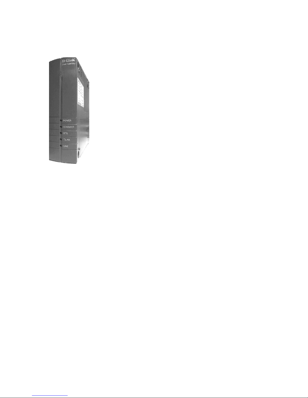
3. Outlet Description
3.1 Front Panel
LED indications on Front Panel along with their colour description
1. POWER: ON- ‘GREEN’ means TA is working on Mains Power.
ON -‘RED ‘ means TA is working on Battery Power.
2. CONNECT: ON -‘GREEN’ means TA is connected to the network at 64K.
ON- ‘RED’ means TA is connected to the network at 128K (MLPPP).
3. DTR/USB: ON –‘RED’ means terminal is connected to PC via DTE (Serial Port).
ON –‘GREEN’ means terminal is connected to PC via USB port.
4. TX/RX: This LED becomes ‘ON’ when data is being sent or received.
5.
: ‘ON’-When TA is connected to S/T interface of NT1. (S0 bus)
LINE
D-LINK ISDN TA DMI-128ESU+
10
Page 11

3.2 Rear Panel Connection
1. DTE DB9-SUB male connector RS232 and USB
Connect to PC or DTE equipment.
Use only one connection port (USB / Serial) at a time to connect to PC.
2. Analog Port TEL-A, TEL-B
Connect to the regular telephone, answering machine or fax machine.
3. AC Power plug
Connect to DC 5V adapter
4. ST
ST interface connection. You can connect to ST interface of NT1 (of ISDN Line), or connect
other ISDN TA phone with S/T interface to make a multi-drop bus connection.
5. FG (Frame Ground)
Optional and not connected in this model
3.3 Side panel
Battery Backup
In case of sudden loss of local power, the TA has a battery power backup solution. A total of 6 AA
batteries are required to backup the TA. Please make sure all 6 batteries are placed correctly, in
the correct polarity. (Use Alkaline Batteries for proper operation)
Battery Mode Operation
In case of sudden loss of local power, the TA will switch to battery backup mode automatically. (If
all 6 batteries had been installed properly.) Under the battery backup mode, all 3 data and analog
ports can be operated normally.
In battery backup mode, with average brand new batteries, the TA can last at least 6 hours in
standby or it can run one analog port continuously for about 1 hours.
Changing Batteries
Please inspect batteries if the TA does not work properly under battery backup mode. If the battery
is low, please replace batteries. We suggest the user to replace all 6 batteries together.
D-LINK ISDN TA DMI-128ESU+
11
Page 12

4 Connection Method
4.1 Connection Procedures
1. Plug in AC power adapter DC 5V 2.8A
2. Connect the ST interface RJ45 modular jack to ISDN port with the RJ45 cable.
3. Connect RS232 cable between TA and PC or TA and USB but not both.
4. Plug in the regular telephone to analog port A or B with RJ11 cable.
5. Connect other ST ISDN phone or TA device with RJ45 cable
A. With this connection method user can use V110, V120, X.75, X.25 protocol to
communicate with other TA.
B. Use PPP or MLPPP to connect with ISP (Internet Service Provider) for Internet access.
C. Use regular telephone make calls
D. Use inner communication between analog port TEL-A and TEL-B.
4.2 Connection With Telephone / Fax
• Locate an available RJ11 modular jack telephone outlet.
Take one end of the modular cord supplied with the TA and plug it into the analog port
•
TEL-A or TEL-B modular jack on the back of the TA.
• Plug the other end of the modular cord into the modular jack on the regular telephone/fax.
4.3 Connection With PC
• Use the attached RS232 cable to connect TA‘s DTE port and PC’s RS232 port or use
USB port with Windows 98 SE/Me/2000/XP
• If the connector type of PC‘s RS232 port does not match, you may need to use the 9-to-25
gender changer to connect between the RS232 cable and PC
D-LINK ISDN TA DMI-128ESU+
12
Page 13

4.4 Connection With Modem
• Connect the telephone to modem‘s port labeled with PHONE then connect modem‘s
LINE port to TA’s TEL A or TEL B port
4.5 Multi-Drop Connection
To make a multi-drop bus connection, you can connect the two TAs by the RJ45 cable
4.6 Connection Notification
Do not connect two or more telephones on the same port. It will affect the Impedance of the telephone set.
D-LINK ISDN TA DMI-128ESU+
13
Page 14

5 Installing The TA
5.1 Packing List
Unpack your TA and make sure that you have the following items:
♦ TA main unit
♦ Female RS232 cable and USB cable
♦ Power adapter 230 V ac DC 5V 2.8A
S/T interface cable
♦
♦ User‘s manual
♦ Windows driver disk
When you opened your package, make sure that all of the above items are included in good
order. If any of the components were damaged, please contact your dealer immediately.
D-LINK ISDN TA DMI-128ESU+
14
Page 15

5.2 What Else You Need
In order to complete your data communication system, you will need the following items:
1. Some type of communication software, if not included (like dialup network).
2. An ISDN U-interface line from the local PTT NT1. This TA gets connected to the ST
interface of the NT1 (which is supplied by your PTT).
5.3 Installing The TA
The following instruction explained how to install the TA with a PC or PC compatible
computer. If you install the TA into a different computer, refer to the manual that came with
or contact your dealer for instructions and assistance.
IMPORTANT:
In PC environment, two serial devices configured to use the same COM port or IRQ
may conflict. Existing multi-I/O cards usually occupies COM1 and COM2 using IRQ4
and IRQ3 respectively. Whereas the COM port setting must be unique, the IRQ can be
shared provided that the related COM port is not being used. For example, if the PC’s
COM2 which uses IRQ3 is not attached to any device (print or mouse, etc.), then your
TA can be set to use COM4 with IRQ3. For maximum flexibility, your PC supports
IRQ2, 3, 4, 5, and 7. However, IRQ2, 5 and 7 should be used only if you have no other
choice. Not all PCs and DOS versions support these IRQs. IBM PC/AT computers and
compatibles should be able to use IRQ5 or 7. Check with your PC dealer or PC manual
for more information.
Turn off the power on the personal computer.
Refer to section 4 to select the adequate method for connection.
5.4 Tips On Configuring Windows 98SE/Me/NT/2000/XP
The following tips will guide you through configuration of the TA on your PC, in the
Windows environment, in a step-by-step manner, with windows screen shots. Proceed with
choosing the correct COM port for your TA.
While installing the ISDN TA through USB port, first install the USB -to-Serial converter
drivers. Then follow the same procedure of installing the modem as shown in Windows
98SE/Me/NT4/2000/XP (RS232 cable connected) procedure.
For other DTE configurations, please refer to the PC manufacturer manual or contact your
local dealer.
D-LINK ISDN TA DMI-128ESU+
15
Page 16
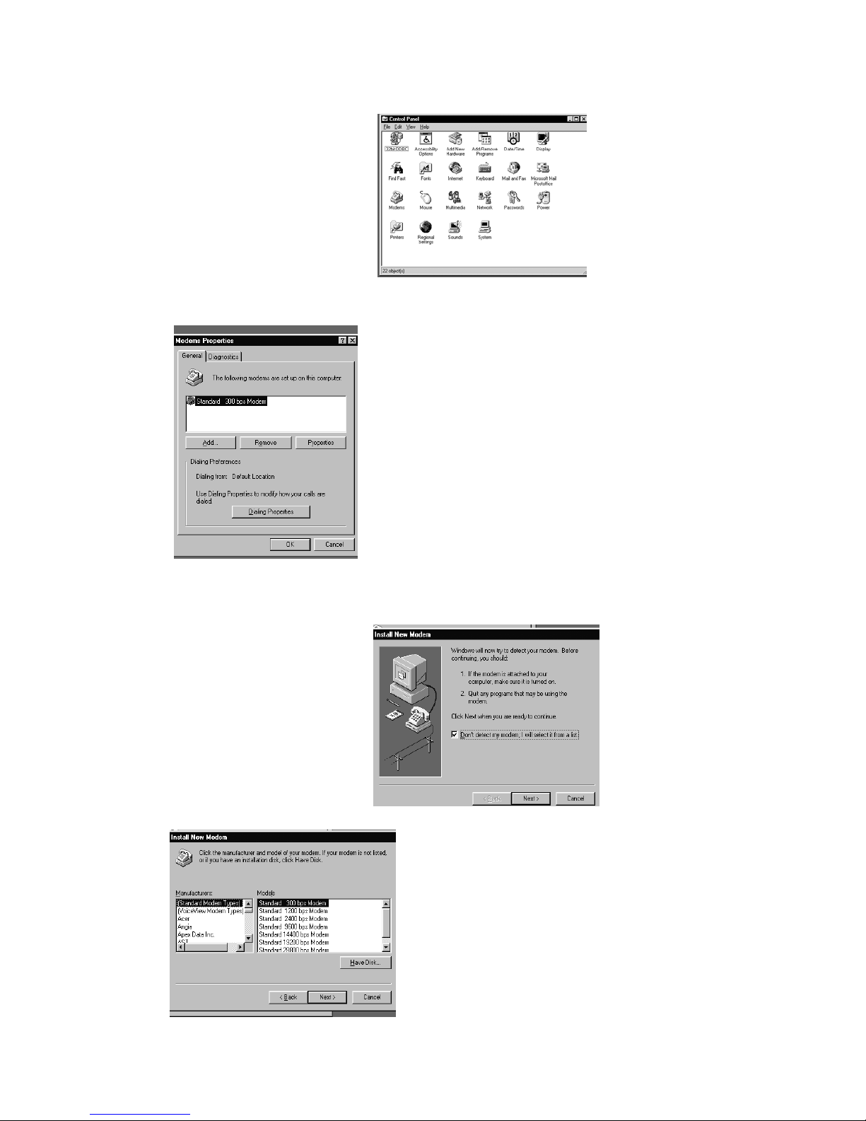
5.4.1 Window 98SE/Me/NT4/2000
1. Choose ‘My Computer’
icon.
2. Open the ‘Control Panel’
menu box as shown on the
right hand side.
After double click Modem
3.
icon, ’Modems Properties’
box appear and show the
existing modems, which has
been installed previously.
Click ‘Add’ button to add
4.
the TA.
(RS232 cable connected)
Tick the box (Don’t
5.
detect my modem)
Click “Next” to
select TA’s driver.
6. In ‘Install New Modem’,
click on ‘Have Disk’ button
and put ISDN TA driver
disk to corresponding drive.
D-LINK ISDN TA DMI-128ESU+
16
Page 17
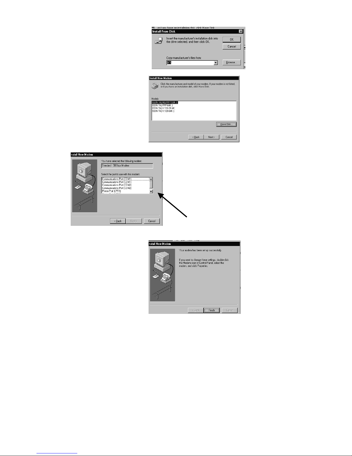
7. Press ‘OK’ if the location of
driver disk is correct.
Otherwise you may press
‘Browse’ button to change.
8. Select the modem to be
installed.
For 64K select “ISDN TA
(PPP-64K)”
For 128K select “
(MLPPP-128K)”
Click ‘Next’ to continue.
10. Press ‘Finish’ to
complete setup.
ISDN TA
9. Choose an available COM
port which is available
(It should not conflict
other devices) and click
‘Next’ button.
** IN CASE OF USB port
installation, select the
USB port, shown in the
drop –down list .. after
the USB-to-serial
converter is installed
5.5 Windows 98SE/Me/2000/XP (USB cable connected)
D-LINK ISDN TA DMI-128ESU+
1. Power Plug into power plug and wait 5 seconds and the plug USB cable
into USB connector of PC and DMI-128ESU+.
17
Page 18

2.
Windows will recognise the new USB device and will ask drivers for for
new USB device. Correct path is Floppy A:. So define search path so that
you specify the installation driver’s path A:\.
3. After USB -drivers installed just add the modem driver into system as
you installed in previous section and select the COM -port, which was
created By USB to Serial driver installation.
4. Power adapter is needed when USB -connector in use because of
Analog ports ringing signals
5.5.1 Linux operating systems with RS 232
1. Use KPPP program and directly TTY port where TA is installed
Or any similar
2. Set port 230400 or 115200 DTE speed 8, N, 1
3. CTS/RTS setting ON
4. PPP / 64K connection AT%A2=5
5. ML PPP 128K AT%2=6
6. In this case do not use IP -header compression
7. If device is not working the slow down AT -command sending speed and
response wait time.
D-LINK ISDN TA DMI-128ESU+
18
Page 19
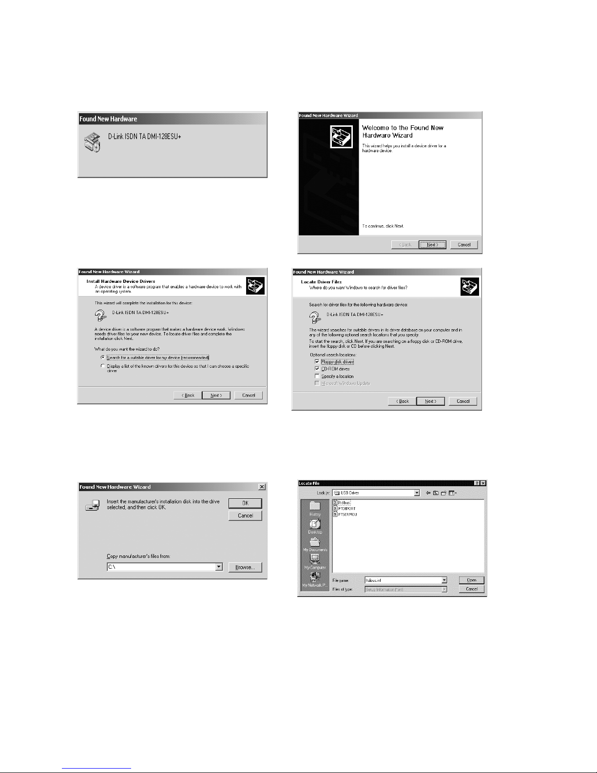
5.5.2 USB Installation Procedure for Win 2000
(USB SERIAL CONVERTER):
1.Win2000 will detect the DMI-128ESU+ and
bring you to the Found New Hardware Wizard.
2.Click ‘Next’ to continue.
3.Select the first item-Search for a suitable
driver for my device [recommended]
4.Click ‘Next’ to continue
5.Click the Specific location in the
Checkbox.
Click ‘Next’ to continue.
6.Click the ‘Browse ‘ button.
D-LINK ISDN TA DMI-128ESU+
7.Choose the location as A:\USB Drivers.
Select the file ftdibus.inf and click ‘open’.
19
Page 20
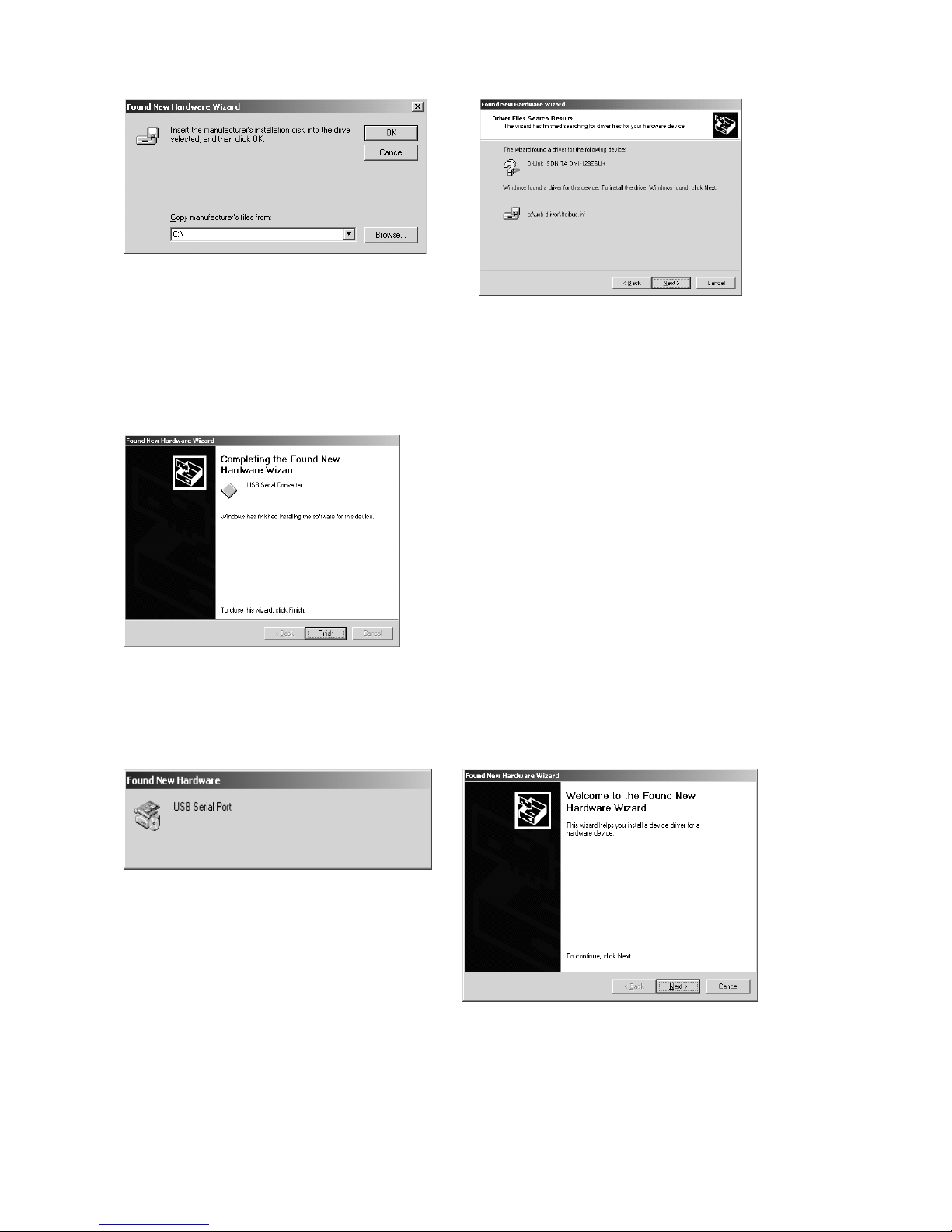
8.Click ‘OK’ button.
9.Click ‘Next’ to continue.
For correct Locations on the screen, please follow remarks indicated on the side of the
Note:
screen snap-shots.
10.The USB Serial
Converter is now installed.
Click ‘Finish’ button
Installation of USB Serial Port (In Win 2000)
1.Win2000 will detect the USB Serial Port
and bring you to the Found New Hardware
Wizard
2.Click ‘Next’ to continue.
D-LINK ISDN TA DMI-128ESU+
20
Page 21
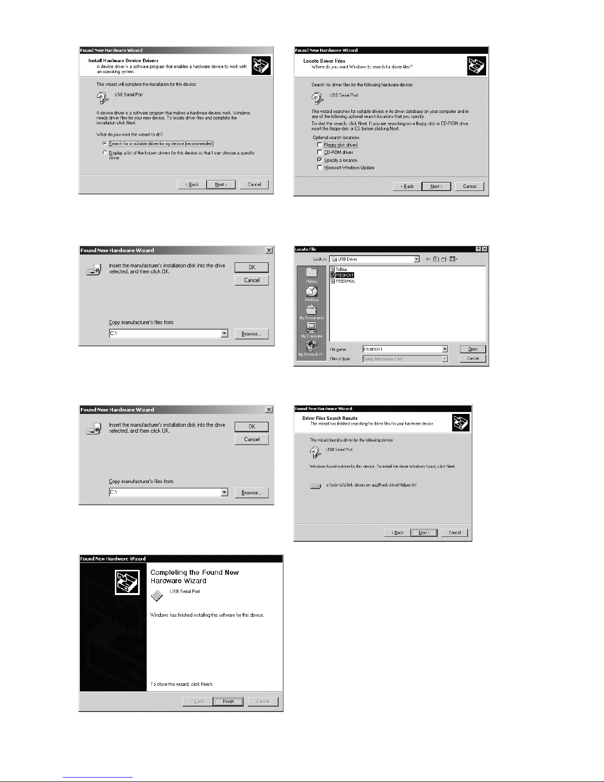
3.Select the first item-
Search for a suitable
driver for my device [recommended]
4.Click ‘Next’ to continue
6.Click the ‘Browse’ button.
5.Check the Specify a location checkbox.
Click ‘Next’ to continue.
7.Choose the location as A:\USB Drivers.
Select the file FTDIPORT and click ‘Open’.
8.Click ‘OK’ button.
D-LINK ISDN TA DMI-128ESU+
9.Click ‘Next’ to continue.
For correct Locations on the screen,
Note:
please follow remarks indicated on the side of
the screen snap-shots.
10.The USB Serial Port is now installed.
Click ‘Finish’ button
21
Page 22
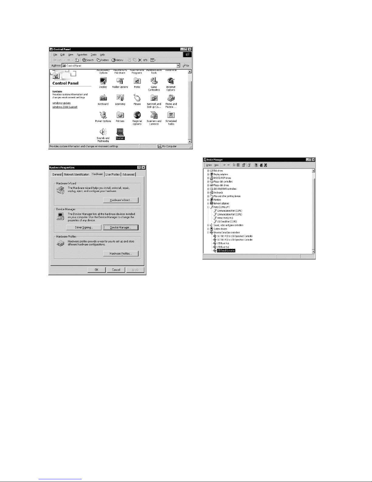
11.Go to the Control Panel, and in System,
to ensure correct installation of the USB
modem
To Ensure that correct installation has taken place, check that in Device manager, when you
expand Universal Serial Bus Controllers you get USB Serial Converter and when you
expand Ports(COM &LPT) you get USB Serial Port(COM 3).
This installation procedure is similar for the WIN 98 SE and WIN ME environment.
AFTER THIS, FOLLOW THE PROCEDURE IN SECTION 5.4.1 FOR INSTALLING THE
MODEM DRIVERS.
D-LINK ISDN TA DMI-128ESU+
22
Page 23
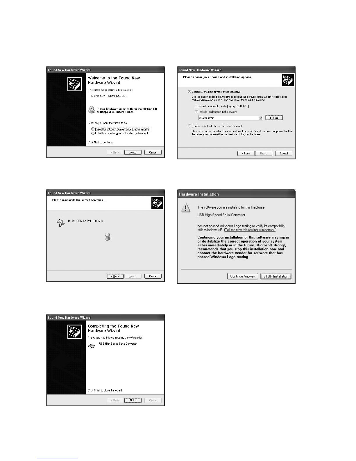
5.5.3 USB Installation Procedure for Win XP
(USB SERIAL CONVERTER):
1. Win XP will detect the DMI-
128ESU+ and bring you to the Found
New Hardware Wizard.
4. This wizard will search for the
required drivers in the given path.
2. Select the second checkbox and give the
correct path for the drivers, A: if the drivers are
on floppy disc.
3.Click ‘Next’ to continue
5. Click “Continue anyway” to proceed
to install the “USB High Speed Serial
Converter”.
6. The USB High Speed Serial Converter is
now installed. Click ‘Finish’ button
D-LINK ISDN TA DMI-128ESU+
23
Page 24
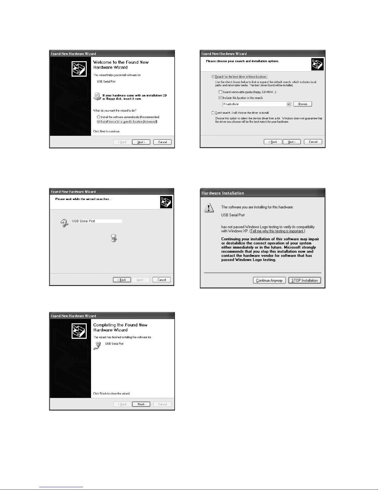
Installation of USB Serial Port (In Win XP)
After installing USB High Speed Serial
1.
Converter DMI-128ESU+, the wizard will
bring you to the Found New Hardware
“USB Serial Port”.
4. This wizard will search for the required
drivers in the given path.
2. Select the second checkbox and give the correct
path for the drivers, A: if the drivers are on floppy
disc.
3.Click ‘Next’ to continue
5. Click “Continue anyway” to proceed to
install the “USB Serial Port”.
6. The USB Serial Port is now installed. Click
‘Finish’ button
D-LINK ISDN TA DMI-128ESU+
24
Page 25
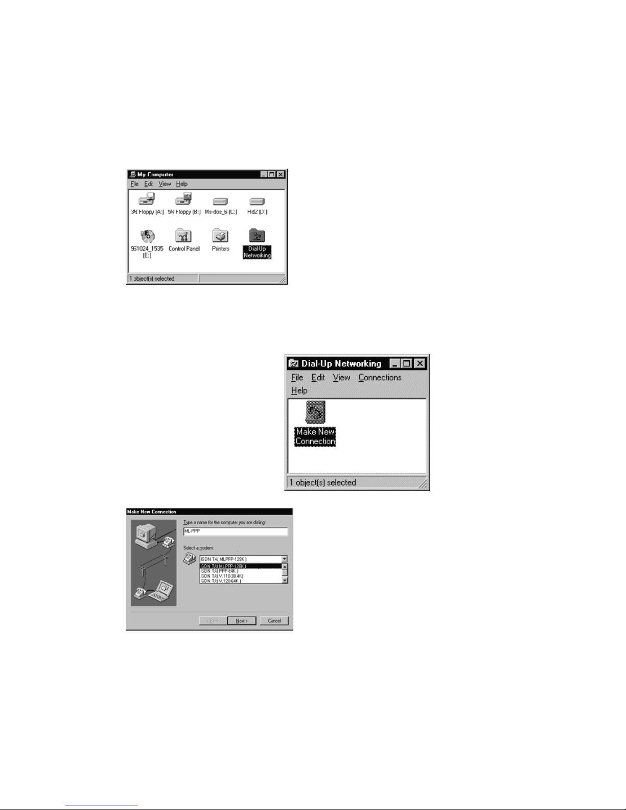
5.5.4 Tips on configuring your Dial-Up Network
After you setup the ISDN TA driver completely. The next step is going to have your Dial-Up
network working. Following tips will guide you how to configure your Dial-Up Network
with Windows 98SE/Me/2000
1) Ensure that you have
1.
installed Dialup server and
Dial-Up Networking in
your windows
environment (Win 98SE).
2) In Win NT ensure that
RAS (Remote Access
Server) is installed.
3) Choose Dial-Up
Network icon from ‘My
Computer’ window.
Click the ‘Make New
2.
Connection’ icon
twice to create a connection
.
Note! If you use ML PPP 128K driver then TCP/IP header compression has to be off
And DNS -values has to be set up correctly in TCP/IP properties.
D-LINK ISDN TA DMI-128ESU+
Choose a protocol for
3.
ISDN TA and give a
name for this connection
and press ‘Next’ button.
25
Page 26
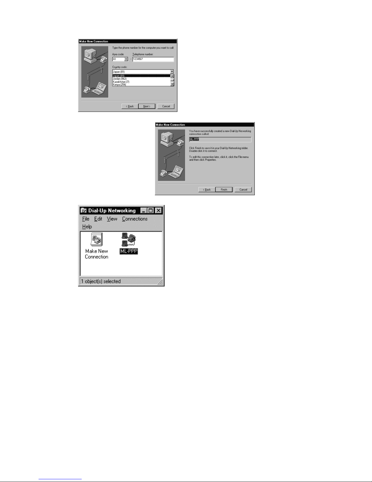
Reconfirm the New
5.
connection and press
Finish button.
Enter the correct
4.
country, area code
and phone number
(The phone number
depends on the ISP
you selected) Then
press ‘Next’ ,if asked
The new connection of
6.
ML-PPP has been
completed and a new icon
will appear. You may
make future modifications
by checking the contents
of function.
D-LINK ISDN TA DMI-128ESU+
26
Page 27

5.6 Verifying Your Connection
Start a communication program (HyperTerminal) and place the computer in terminal mode.
Refer to your computer manual to find out the appropriate commands to do so.
Follow these procedures to verify your installation:
1. Type
AT [Enter]
If your system is operating properly, the TA will respond with ‘OK’ message to your
screen and will wait for the next command.
Use your communication software to prepare your computer to dial a data call.
2.
For example, you can test the data connection under V.110 protocol with the following
procedures.
AT%A2 = 1 ; Select V.110 communication protocol.
ATD 5552121 ; Where 5552121 is the called party’s telephone number with V.110
protocol setting.
After ATD5552121 you can see the TX/RX LED is lighted and then, the ‘CONNECT’ or
‘NO CARRIER’ message will be displayed.
CONNECT
; Means TA connected with the Called Party.
NO CARRIER; Means TA did not connect with the Called Party, may be due to
Called Party busy.
D-LINK ISDN TA DMI-128ESU+
27
Page 28

6. AT COMMAND
6.1 Description of AT Command
Hayes command set is a standard for Hayes modem commands for its Smart modem 300. Most
modem manufactures adopted this command set in order to have Hayes compatible. The command
set used by the Smart modem 300, as well as most modems or TAs today (with a few additional
new advanced commands), is known as the AT command set. AT stands for attention, and is
placed in front of actual content of command so that the TA knows what follows is an command
directed at the modem or TA. With the exception of some “A/” and “+++” command, “AT”
command is the process to place command to the TA.
Different modems or TA’s may have slightly different command sets, but generally speaking, most
of the TAs follow the standard set by Hayes.
6.1.1 AT Command
When you connect terminal equipment (like PC) with the TA, after typing AT command ending
with [ENTER] key, TA will process the command and then return the result code to the terminal
equipment. Each AT command must starts with “AT” and end with [ENTER] key (with the
exception of “A/” and “+++” commands).
Command Format
The following is the format of AT command:
AT
Command Value Command Value CR LF
Result code has two styles (Verbose and Numeric). The following are their formats:
CR LF Result
CR LF
code(Verbose)
Result code (Numeric) CR
S register
The S register is used to store the settings including
auto answer mode
escape sequence character
V.110 connect speed ..... etc.
D-LINK ISDN TA DMI-128ESU+
28
Page 29

If you want to change the value of S register, you can use the ATS command.
6.2 AT Command
6.2.1 AT Command Overview
Command Description Default
ATA Manual answer
ATD Dialing
ATEn Echo command ATE1
ATH Hang up
ATIn Interrogate the TA product status
ATL Dialing the latest number
ATO Return to on line state
ATQn Return result codes select ATQ0
ATSn=x Set S register
ATVn Verbose mode ATV1
ATWn Connection message format select ATW0
ATXn Result code set select ATX0
ATZn Reset recall user profile
AT&Cn CD signal control AT&C1
AT&Dn ER signal control AT&D2
AT&F Recall factory default setting
AT&Kn Flow control AT&K3
AT&Sn DR signal control AT%S0
AT&Vn Display system configuration
AT&Wn Write user profile
AT&Yn Load user configuration when power on AT&Y0
AT%A2=n Data port protocol selection Default is PPP 64K
AT%A5=n Set enbloc or overlap sending mode when dialing telephone number AT%A5=0
AT%D Data port setting display
AT%DC Show disconnect cause, source, charge
AT%FAPPS Re-Flash the new software
AT%N=x Set data port directory number / sub-address
AT%Sn Data port call screen function enable AT%S1
AT%Z1 Software reset
AT$AAn Set analog port A voice information capability in answer mode AT$AA2
AT$AN=x Set analog port A directory number / sub-address
AT$AOn Set analog port A voice information capability in originate mode AT$AO0
AT$APn Dial pause set up for analog port A AT$AP1
AT$ASn Screen incoming call for analog port A AT$AS1
AT$BAn Set analog port B voice information capability in answer mode AT$BA2
AT$BN=x Set analog port B directory number / sub-address
AT$BOn Set analog port B voice information capability in originate mode AT$BO0
AT$BPn Dial pause set up for analog port B AT$BP1
AT$BSn Screen incoming call for analog port B AT$BS1
AT$CC Display advice of accumulate charge
AT$CD Display all analog port setting
AT$CGn Global call select setting AT$CG2
AT$CIn Enable inner communication AT$CI1
AT$CPn Receiver priority setting AT$CP1
AT$CSn Select supplementary service function AT$CS1
AT$CZn Initialize charge
AT%A2=5
D-LINK ISDN TA DMI-128ESU+
29
Page 30

AT$CFn Call forwarding function select AT$CF1
AT*CFAn Enable call forwarding for analog port A AT*CFA0
AT*CFBn Enable call forwarding for analog port B AT*CFB0
AT*CFGn Enable call forwarding under global call AT*CFG0
AT*CFA= Set call forwarding number for analog port A
AT*CFB= Set call forwarding number for analog port B
AT*CFG= Set call forwarding number for global call
AT$EUn Set a-law or u-law coding
AT $ ES N DTMF START CODE “A”
AT$ E RN S et CID between 1st and 2nd ring
AT$EU1
AT$ES1
AT$ER1
AT $ AC n
AT * BC n
AT * ID n
AT$EDN
Enable to send caller ID for analog port A AT$AC1
Enable to send caller ID for analog port B AT$BC1
Enable to send caller ID for data port
Setup DTMF caller ID or FSK
AT * ID 1
AT $ ED 1
AT*W=n Save settings to flash memory
ATUn Resource BOD setup
ATU1
A/ Repeat last command
+++ Escape sequence from data mode
D-LINK ISDN TA DMI-128ESU+
30
Page 31

6.2.2 AT Command List
* means default setting
Command Description Value Remark
ATA
AT D
AT D Sn
ATEn
AT H
AT I n
ATL
AT O
AT Q n
AT S n= x
AT V n
AT W n
AT X n
ATZn
AT & Cn
AT & Dn
Manual answer
Answer an incoming data call
Dialing
Dial the destination number
Max main address: 20 digits
Max sub-address: 5 digits
Speed dialing
Echo command
Define whether characters are echoed back
from the TA to the DTE within command
mode.
Hang up
Hang up the connection
Interrogate the TA product status
Dialing the latest number
Return to on-line state
Return result codes select
Defines whether or not the TA will issue
result codes to the DTE
Set S register
Change S register value
Verbose mode
Defines the form of result codes returned by
the TA
Connection message format select
Defines the type of (extended) negotiation
result codes to return.
Result code set select
Description Select the result code set.
Reset/recall user profile
The user configuration stored in the nonvolatile memory is recalled to become the
active configuration.
CD signal control
Defines what the TA outputs as the DCD
(CD) signal on the DTE interface
DTR signal control
Defines how the DTR (ER) signal is
interpreted by TA.
0-9
+
0-19 Speed dialing number
0
*1
Type ATH during the
0
1
3
6
ATD4125678
Return from command mode to data mode
*0
1
n
x
0
*1
*0
1
*0
1
0
1
0
*1
0
*2
ATD4125678+ 123
• Dialing digits
• Sub-address delimiter
• No echo
• Echo
will reject the
RING
call
• Requests the TA product code
• Checksum value
ROM Part Numbers and Revision
•
Supported switching type
•
Then ATDL will dial 4125678 again
• Result code returned
• Not returned
• S register number
• Setting value
• Numeric form responses enabled
• Verbose responses enabled (English
responses)
• Negotiation codes reported in 1
line format : (CONNECT)
• 3 line format (Hayes format)
(CONNECT xxx)
(PROTOCOL xxx)
(CARRIER xxx)
• Data result codes 0-4 enabled
• All supported data result codes
Enabled
• Reset the TA and recall user profile
• Reset the TA and load default value
(Except stored dial number, own address, sub-address and
accumulated charge)
• DCD (CD) signal on at all time.
(TA‘s DCD signal follow PC’s DTR)
DCD (CD) signal on at only
•
communication time.(DCD signal
high during communication time)
• DTR signal consider on at all
time.
(TA won‘t detect DTE’s DTR,
TA consider DTR is always on)
• TA will detect DTE‘s DTR (ER) Signal
D-LINK ISDN TA DMI-128ESU+
31
Page 32

AT & F
AT & Kn
AT & Sn
AT & Vn
AT & Wn
AT & Yn
AT&Zn=x
AT%A2=n
AT%A5=n
AT % D
AT % DC
AT%FAPPS
AT % N= x
AT % Sn
AT % Z1
AT$AAn
AT$AN=x
Recall factory default setting
Flow control
DR signal control
Defines how the DSR (DR) signal is
handled by the
Display system configuration
Cause the TA to display its current
configuration
Write user profile
TA
The TA ‘s active configuration will
be stored into the non-volatile
memory as User profile
Load user configuration when power on
Register speed dial number
Data port protocol selection
Select the protocol on BOD channel
Enbloc/overlap sending mode
Select the sending method for telephone
number (refer also AY*W0, AT*W1)
Data port setting display
Show disconnect cause, source, charge
Re-Flash the new software
Set data port directory number / subaddress
(eg. AT%N=12345678 + 12345)
Data port call screen function enable
Software reset
Set analog port A voice information
capability in answer mode
Set analog port A directory number / subaddress (Not used in Finland)
Eg. AT$AN1234567812345
The factory configuration contained in the
ROM is loaded to become the TA’s
configuration.
0
*3
4
*0
1
• No flow control
• Hardware flow control (RTS/CTS)
• Software flow control (Xon/Xoff)
• TA‘s DSR (DR) signal follows DTE’s
DTR
• DSR (DR) signal on at only
communication time.
(DSR signal high during
communication time)
0
2
0
1
0
1
n
x
1
2
4
*5
6
8
14
*0
1
Display all corresponding setting
Display the disconnect reason and
x
0
*1
Reset all internal state of TA
0
1
*2
x
• Displays the current
configuration
• Display Directory Numbers and all
stored phone numbers
• Write user profile 0
• Write user profile 1
• Use user profile 0 as active Profile
when power up
• Use user profile 1 as active Profile
when power up
• n = 0-19
• x = telephone number
• V. 1 1 0
• V.120
• X.25 on D
• PPP
• MLPPP
• X.75
• Channel Bundling
• Overlap sending
The dialing telephone will be sent to
network after TA detect the ending digit
• Enbloc sending
The dialing telephone number will be
sent to network immediately whenever
the user dialing each digit
connection fee
• x=telephone number
main - address: max 20 digits
sub - address: max 5 digits
• Accept incoming call if the calling
party number is in the call screen table.
• Accept all incoming call
• Accept speech
• Accept 3.1kHz audio
• Accept both
• X = telephone number
Main - address: max 20 digits
Sub - address: max 5 digits
D-LINK ISDN TA DMI-128ESU+
32
Page 33

AT$AOn
AT $ AP n
AT $ AS n
AT $ BA n
AT$BN=x
AT $ BO n
AT $ BP n
AT $ BS n
AT $ CC
AT $ CD
AT $ CG n
AT $ CI n
AT $ CP n
AT $ CS n
AT $ CZ n
AT $ CF n
AT*CFAn
AT *CFBn
Set analog port A voice information
capability in originate mode
Dial pause set up for analog port A
Screen incoming call for analog port A
Set analog port B voice information
capability in answer mode
Set analog port B directory number / subaddress
(eg. AT$BN=12345678 + 12345)
Set analog port B voice information
capability in originate mode
Dial pause set up for analog port B
Screen incoming call for analog port B
Display advice of accumulate charge
Display all analog port setting
Global call select setting
If the incoming call did not contain the
called party number then TA had to
determine ring mechanism
Enable inner communication
Receiver priority setting
This function only available when
set AT$CG2
Select supplementary service function
Initialize charge
AT$CZn =MM-DD-YY
Call forwarding function select
Select call forwarding by local or
Network.
Enable call forwarding for analog port A
Enable call forwarding for analog port B
*0
1
*1
2
3
4
0
*1
0
1
*2
x
*0
1
*1
2
3
4
0
*1
Display advice of accumulate charge (data
Display all of the setting for analog port A
0
1
*2
0
*1
*1
2
3
1
2
3
*1
2
3
4
5
*0
1
• Select speech
• Select 3.1kHz audio
• 5sec
• 9sec
• 11sec
• 13sec
• Accept incoming call if the calling
party number is in the call screen table.
• Accept all incoming call
• Accept speech
• Accept 3.1kHz audio
• Accept both
• x = telephone number
main - address: max 20 digits
sub - address: max 5 digits
• Select speech
Select 3.1kHz audio
•
• 5sec
• 9sec
• 11sec
• 13sec
• Accept incoming call if the calling
party number is in the call screen table.
• Accept all incoming call
port, analog port A, analog port B)
and B
• Ring TEL-A only
• Ring TEL-B only
• Ring both TEL-A and TEL-B
• Disable inner communication
• Enable
• Ring TEL-A/B alternatively
• Ring TEL-A 10 times first
Ring TEL-B 10 times first
•
Note: Follow chapter 10.
• Initialize TEL-A to zero charge
• Initialize TEL-B to zero charge
• Initialize data port to zero charge
Local call forwarding
•
• Network forwarding, ID=32
• Network forwarding, ID=33
• Network forwarding, ID=34
• Network forwarding, ID=35
• No forwarding
If the incoming call is for TEL-
•
A, it will forward automatically
to the phone number defined by
AT*CFA=xxxxxx
*0
1
• No forwarding
• If the incoming call is for TEL-
B, it will forward automatically
to the phone number defined by
AT*CFB=xxxxxx
D-LINK ISDN TA DMI-128ESU+
33
Page 34

AT*CFGn
AT * CF A= x
AT * CF B = x
AT * CF G = x
AT*Ln
Or
AT $ EU 1
AT*W0=n
AT*W1=n
AT $ ED x
AT $ Es x
AT $ ER 1
AT $ AC x
AT $ BC x
AT*Idn
AT U n
A/
+ + +
Enable call forwarding under global call
Set call forwarding number for analog port
A
Set call forwarding number for analog port
B
Set call forwarding number for global call
A-law or u-law coding select
Set the dialing interpretation of ‘#’
Set the dialing interpretation of ‘*’
Set DTMF caller id to analog ports
DTMF CALLER ID start code
st
Caller ID between 1
Enable to send caller ID for analog port A
Enable to send caller ID for analog port B
Enable to send caller ID for data port
Resource BOD setup
Enable/Disable the resource BOD function
Repeat last command
TA will re-execute the most recently
received command line
Escape sequence from data mode
and 2nd ring
*0
1
• No forwarding
If the incoming call is a global
•
call it will forward automatically
to the phone number defined by
AT*CFG=xxxxxx
x
x
x
*0
1
*0
1
2
*0
1
2
0
*1
D
*A
B
Forced
0
*1
0
*1
0
*1
*0
1
This command does not use the AT prefix
Escape from the data mode
• x=forward phone number
• x=forward phone number
• x=forward phone number
• A-law coding
For European, China, Australian and
etc
• U-law coding
For American, Japan and etc
• ‘#’ is interpreted as a normal digit
‘#’ is interpreted as a sub-address
•
delimiter
• ‘#’ is interpreted as an ending digit. In
enbloc sending mode TA will send the
dialing number after received the
ending digit or after timeout
• ‘*’ is interpreted as a normal digit
• ‘*’ is interpreted as a sub-address
delimiter
• ‘*’ is interpreted as an ending digit. In
enbloc sending mode TA will send the
dialing number after received the
ending digit or after timeout A-law
coding
For European, China, Australian and
etc
• Fsk caller ID
DTMF caller ID (Finland)
•
• A -LETTER START CALLER ID
• SEQUENCE IN FINLAND
Default always
•
• Not to send TEL - A telephone number
under outgoing call
• Send TEL - A telephone number
• Not to send TEL - B telephone number
under outgoing call
• Send TEL - B telephone number
• Not to send data port telephone number
under outgoing call
• Send data port telephone number
• Disable resource BOD function
• Enable resource BOD function
nor does it require a carriage return to enter
D-LINK ISDN TA DMI-128ESU+
34
Page 35

6.3 S Register
Number Meaning Range Unit Description Default
0 Auto answer 0
1 - 255
1 RING count 0 - 255 Time
2 Escape character 0
0 - 127
3 Carriage Return 0 - 127 ASCII
4 Line Feed 0 - 127 ASCII
5 Back Space 0 - 32 ASCII
12 Escape sequence
Prompt time
25 DTR detection time 0 - 255 0.01sec
26 CS delay time 0 - 255 0.01sec
37 V.110 speed set 5
107 Throughput BOD
criteria (monitor B -
ch throughput)
141 BOD - Add monitor
Time
143 BOD - Add last time 0 - 255 Sec The throughput must greater than S107
144 BOD - Cut monitor
Time
146 BOD - Cut last time 0 - 255 Sec The throughput must less than S107 and
0
1 - 255
6
15
17
27
50
0 - 6 10kbps
0 - 255 Sec Average calculation time for adding one
0 - 255 Sec Average calculation time for dropping
Time
ASCII
20ms
• Manual answer
• Auto answer the incoming data
call after defined counting
• Stored the RING count
• Disabled
• Use the ASCII value as escape
character
• Use the ASCII value as CR
• Use the ASCII value as LF
• Use the ASCII value as BS
• Do not check guard time
• Check guard time
• DTR recognized time
• Delay between lost carrier and
Hang up (RTS to CTS)
• 5 = 1200bps
• 6 = 2400bps
• 15 = 4800bps
• 17 = 9600bps
• 27 = 19200bps
• 50 = 38400bps
• 0 = do not monitor
• 1 = 10kpbs
• 2 = 20kbps
• 3 = 30kbps
• 4 = 40kbps
• 5 = 50kbps
• 6 = 60kbps
B - ch
and lasted S143 time, after
Such criteria, TA will add one B-ch
connection
one B-ch
lasted S146 time, after such criteria, TA
will drop one B-ch connection
0
0
43
13
10
8
50
20
1
50
0
5
30
5
30
D-LINK ISDN TA DMI-128ESU+
35
Page 36

6.4 Result Code
Data Result
Code
0 OK Normal response
1 CONNECT Connected
2 RING Incoming call ringing
3 NO CARRIER No carrier detected
4 ERROR Error operation
7 BUSY Busy state
5 CONNECT 1200 1200bps connection
10 CONNECT 2400 2400bps connection
11 CONNECT 4800 4800bps connection
12 CONNECT 9600 9600bps connection
14 CONNECT 19200 19200bps connection
28 CONNECT 38400 38400bps connection
18 CONNECT 57600 57600bps connection
19 CONNECT 64000 64000bps connection
20 CONNECT 115200 115200bps connection
21 CONNECT 230400 230400bps connection
46 CARRIER 1200 1200bps carrier detected
47 CARRIER 2400 2400bps carrier detected
48 CARRIER 4800 4800bps carrier detected
50 CARRIER 9600 9600bps carrier detected
54 CARRIER 19200 192000bps carrier detected
56 CARRIER 38400 384000bps carrier detected
39 CARRIER 48000 48000bps carrier detected
57 CARRIER 57600 57600bps carrier detected
59 CARRIER 64000 64000bps carrier detected
83 PROTOCOL: V.120 V.120 connection
85 PROTOCOL: V.110 V.110 connection
86 PROTOCOL: PPP PPP connection
88 PROTOCOL: MLPPP MLPPP connection
Word Format Description
D-LINK ISDN TA DMI-128ESU+
36
Page 37

7. Easy Setup From Telephone Keypad
The TA provides an easy configuration way through the analog port. If you use TEL-A port then
you can setup the corresponding attributes only for TEL-A. If you are using TEL-B then you can
setup the configuration for TEL-B only.
Easy Setup
Operation
Press Flash /
R first
** 1 2 8
Flash/
On-hook
* *
# * #
0 0 * n Global Call Select
0 2 * n Receive Priority
0 5 * n Factory Default
0 7 * n Call Forwarding Criteria
0 8 * n Local/Network Call
0 9 * n * x Forwarding Number
1 0 * x
1 1 * n * x Register Call Screen
1 2 * n Enable Caller-ID
D-LINK ISDN TA DMI-128ESU+
Enter into programming
Mode
Cancel setting Cancel the current operation
Store setting into active
profile
Store setting into
Non-volatile memory
Forwarding
Register Telephone
Number
Number
Meaning Value Description
Instruct TA to enter into
programming mode
Save the current setting into
active memory profile
Save the current setting into
NV-RAM
n=0 Ring TEL-A only
1 Ring TEL-B only
2 Ring TEL-A and TEL-B
n=0 Disabled inner communication 0 1 * n Inner Communication
1 Enabled
n=1 No receive priority
2 Ring TEL-A first
3 Ring TEL-B first
n=1 Call is forwarding when received an
incoming global call (without called
party number)
2 Call is not forwarding when received
an incoming global call
3 Call is forwarding when received an
incoming call for
TEL-A
4 Call is not forwarding when received
an incoming call for
TEL-A
5 Call is forwarding when received an
incoming call for
TEL-B
6 Call is not forwarding when received
an incoming call for
TEL-B
n=1 Local call forwarding
2 Network forwarding, ID=32
3 Network forwarding, ID=33
4 Network forwarding, ID=34
5 Network forwarding, ID=35
n=1 Global call forwarding no.
2 TEL-A call forwarding no.
3 TEL-B call forwarding no.
x=tel
number
n=1-5
x=tel
number
n=0 Do not send out caller-ID when
1 Send out caller-ID when made
Register telephone number for
TEL-A/TEL-B
Register call screen number for TEL-
A/TEL-B
made an outgoing call
Outgoing call
37
Page 38

7.1 Entering Programming Mode
To enter into the programming mode from telephone sets, please follow the steps below:
A) Use regular telephone set with DTMF -codes and plug into analog port A (TEL-A) or B (TEL-
B) Pick up the telephone you and wait for dial tone.
C) Press flash / R -button
and then ** 1 2 8 one the telephone keypad then you
will hear a confirmation tone which indicate that the TA is now under the programming mode.
7.2 Setup Configuration
To setup the corresponding settings, please check the above Easy Setup Table and execute the
following steps.
A). Press 0 0 * 0 to set global call select - ring TEL - A only (for example)
B). Press * * to store the setting into active profile.
C). Repeat the procedure A) and B) for other settings.
D). When finished with all settings, press
to store all the updated settings into the
* # *
non - violate Memory.
7.3 Storing The Setting
After you performed the * # * sequence, even when there is a power outage. The modified settings
will still stored in the non-violate memory. After power resumes, you can recall the setting from
user profile 0 or 1. If you hang up the phone before you execute the * # * sequence, then the TA
will abort from the programming mode and return to idle mode.
D-LINK ISDN TA DMI-128ESU+
38
Page 39
8. Re-Flash the New Software
8.1 Normal Re-Flash Procedure
To provide the upgraded software function in the future. The TA had been installed with the flash
EPROM for re-flash the new software function. Usually you should get the zipped (.ROM) file
from your local dealer directly or from your local agent’s Web Home Page. After you get the
.ROM file please follow the following procedure carefully.
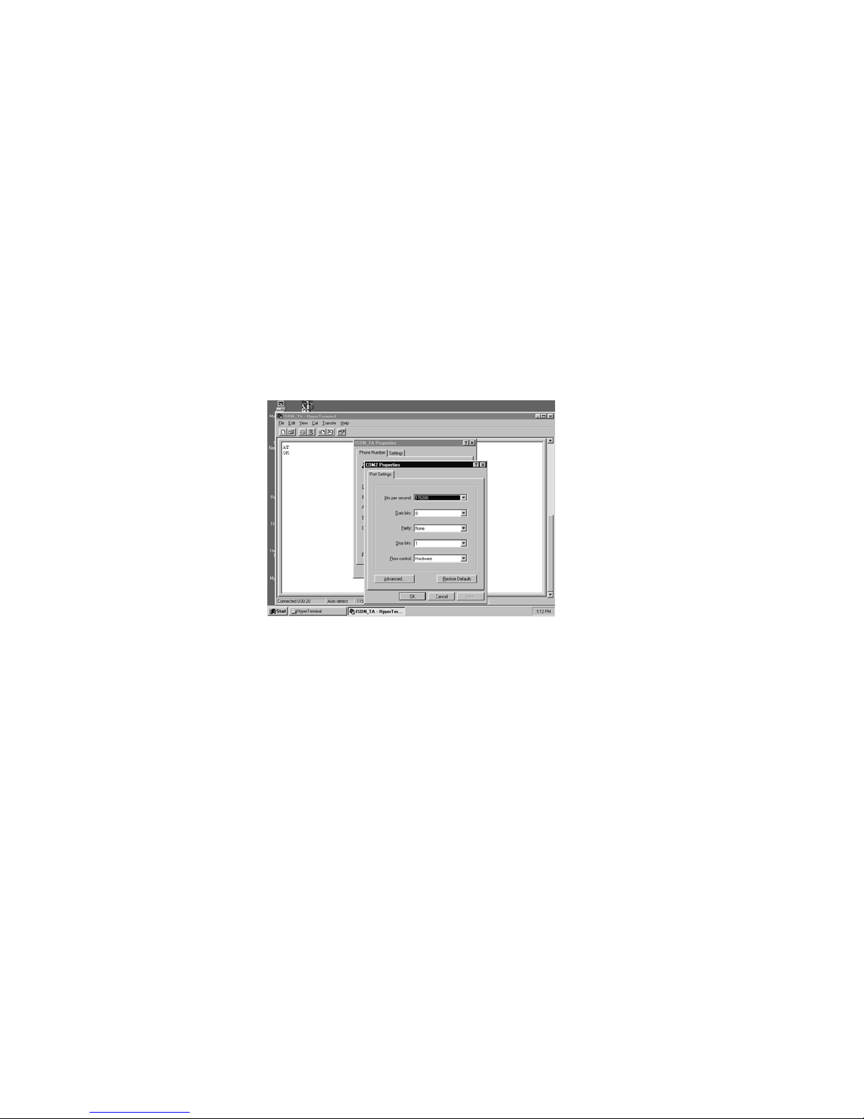
(1) Use any terminal program that support ASCII file transfer function, like HyperTerminal.
(2) Enter into the terminal mode and make sure that the terminal program had set the following
configuration.
. 115200-baud rate
. 8 data bit, no parity, 1 stop bit (8N1)
. CTS/RTS hardware flow control
(3) Type AT and check TA responded with “OK”
(4) Type AT%FAPPS the screen will display the following message.
AT%FAPPS Application Upgrade
FLASH PROGRAM VERSION 1.4
Erase and reprogramming flash EPROM contents (y/n)?
(5) If you enter “n” then screen displayed
“Reset modem to continue”.
You need to power off and power on AFTER flashing TA to restart.
If you type “y” the screen will display:
*** WARNING ***
Erasing Flash Memory
Flash EPROM Upgrade Procedure
Ready for ASCII download
CTS (hardware) flow control
38400,8,N,1
>
(6) After you see the “>” character is appeared, you should select the new upgraded
D-LINK ISDN TA DMI-128ESU+
39
Page 40
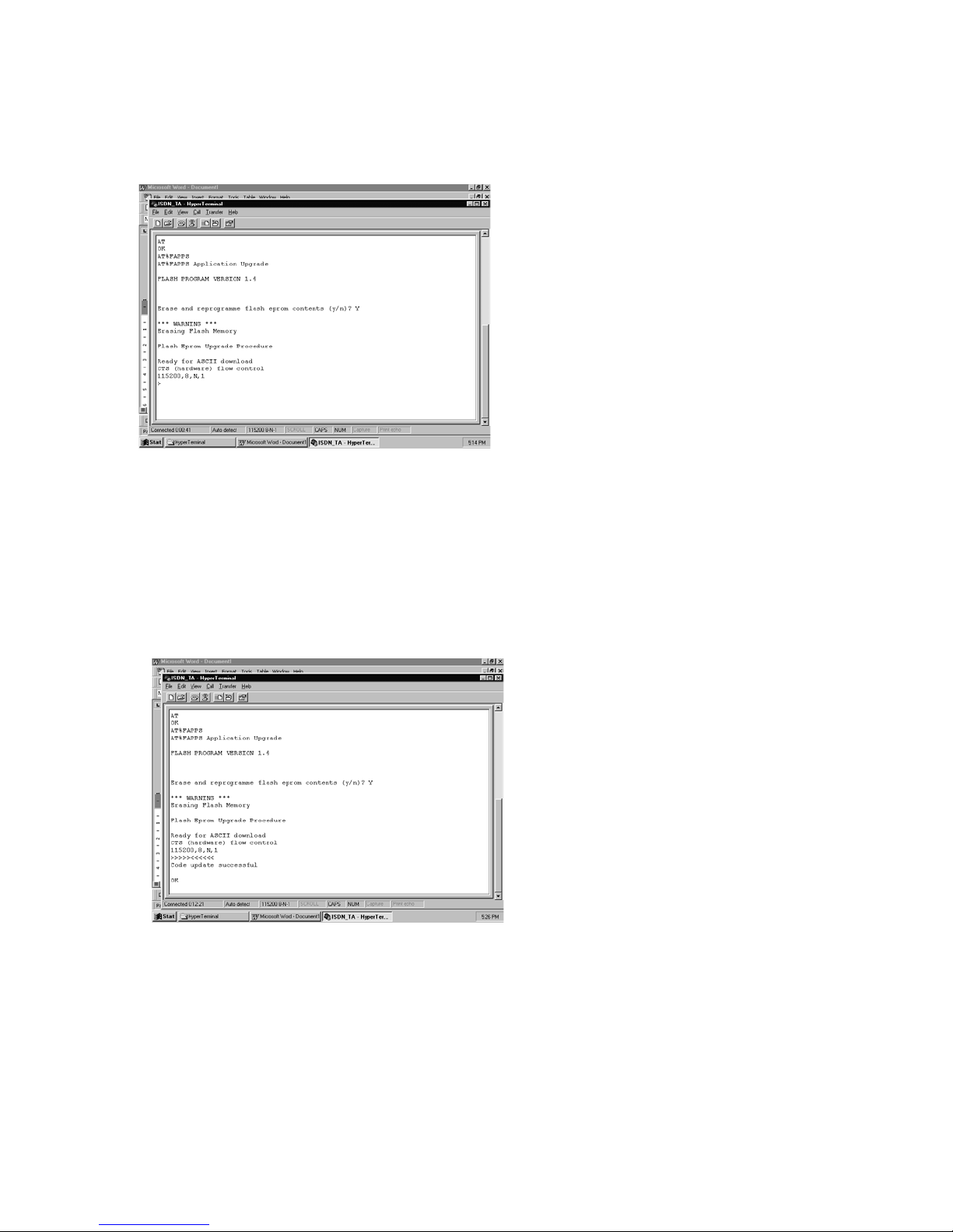
software from the correct path. Select Transfer ->> Send Text File. Here give path of the .rom
file (*.ROM). Then click OK to start download. The screen will show the “>>>>>>>>>>” and
“<<<<<<<<<<” alternatively to indicate TA is downloading now.
(7) After finished the download new software, screen will display
“Code update successful”
“OK”
Normally it takes about 10 minutes to finish re-flash.
(8) After you see the message it means the download is completely already. You
need to power off and power on TA again to restart.
Type ATI3 to inspect the new software version.
(9)
8.2 Failed Re-Flash Procedure
Sometimes during the re-flash procedure, due to some accidents like: local power is off; PC is shut
down, RS232 cable is disconnected and etc. To prevent any kind of failed re-flash operation, TA
provides a so-called Minimum Operating Mode. When you failed to re-flash the new software,
TA will detect the failed re-flash internally.
D-LINK ISDN TA DMI-128ESU+
40
Page 41

You must follow the procedures as below step-by-step.
(1) Power off TA.
(2) Check the RS232 cable is connected with PC well.
(3) Change the Terminal program to 38400 baud, 8N1, CTS/RTS hardware flow control.
(4) Entering the terminal mode again.
(5) Power on TA again, you will see the screen display:
“ Erase and reprogramming flash EPROM contents (y/n) ?
(6) Enter “y” and follow the steps from 8.1 (6) as stated above. Then you can still
finish the re-flash procedure. And you will see “38400, 8, N, 1” instead of
“115200, 8, N, 1”. Due to the baud rate is slower therefore it takes about 10
minutes to finish re-flash.
D-LINK ISDN TA DMI-128ESU+
41
Page 42
9 Trouble Shooting
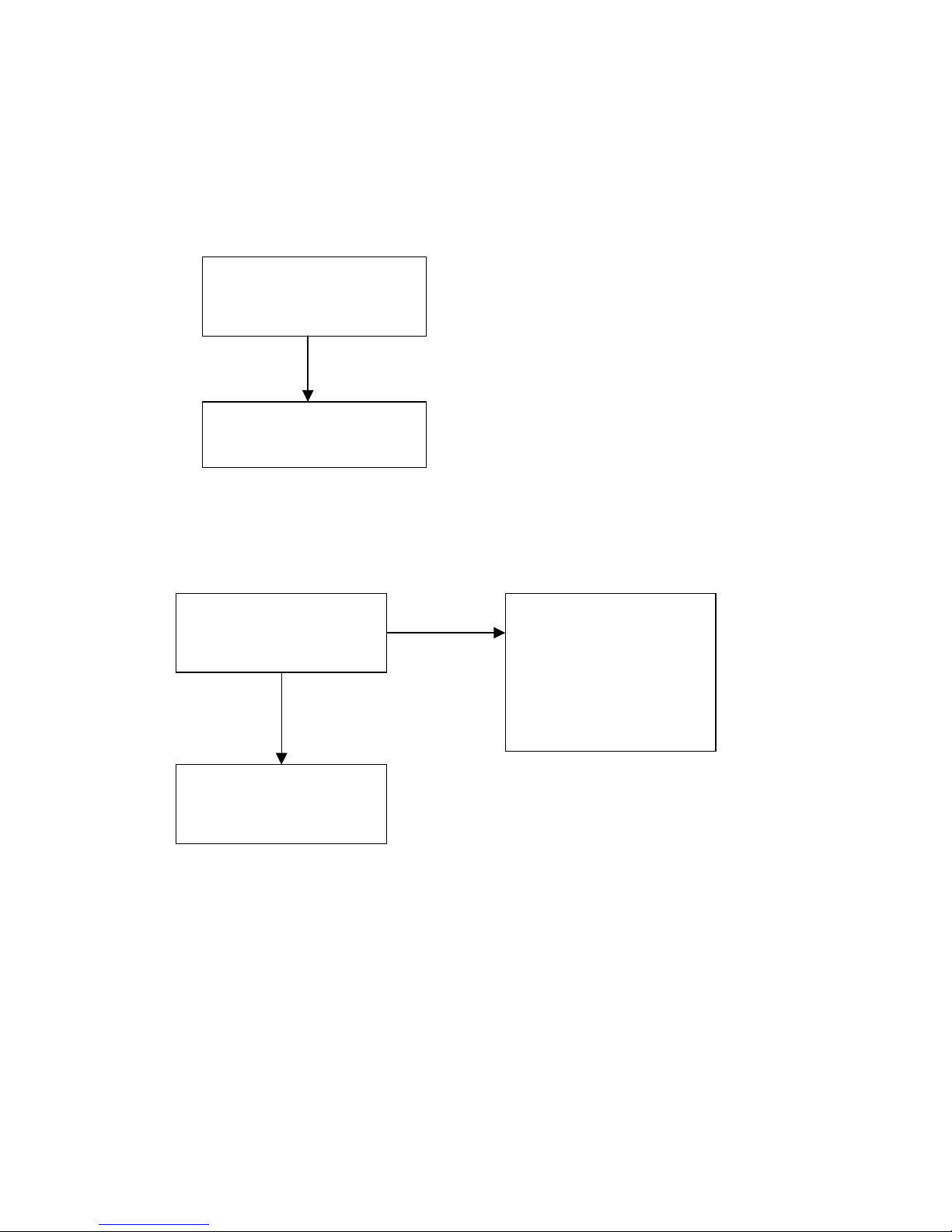
Here are some flow charts of troubleshooting, which may help you resolve frequently encountered installation
problems.
9.1 Power Switch On but POWER LED is not lit.
9.2 DTR LED not lit, and the TA does not connect.
Please Check Power. Does the
power cord connected ?
No
Connect the power cord.
Are all connections to the TA
properly and correctly
connected?
No
Yes
1. Please confirm that the
S/T line to local switch
center is connected
properly.
2. Confirm that the S/T of
local switch center is
working.
Turn off the TA. Reconnect all
connectors before turning on
the TA.
D-LINK ISDN TA DMI-128ESU+
42
Page 43
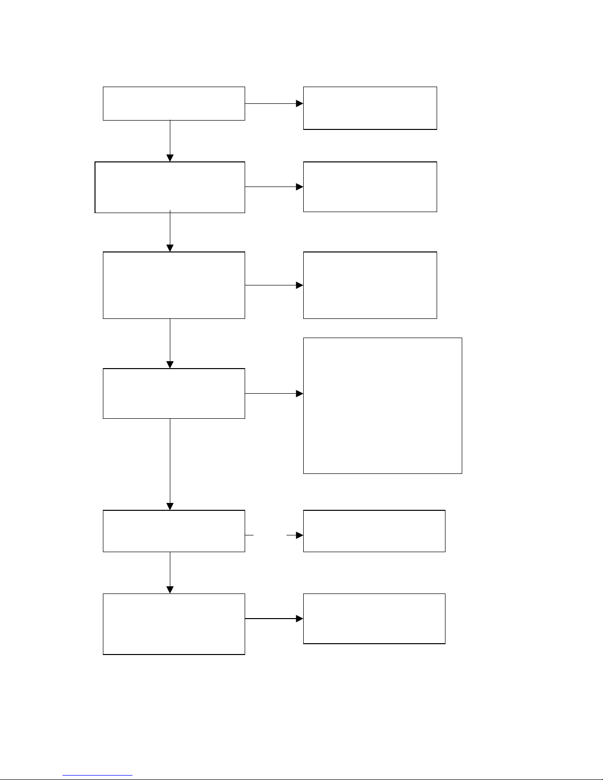
9.3 Type “AT’, but the TA does not respond with “OK’ message
Is the “POWER” LED lit?
Does the attention code
contain both upper and lower
case letters? (i.e. aT or At?)
Is COM Port Setting
correct?
“Tx/Rx” LED does not flash
when entering command
from terminal (DTE)
Yes
No
Yes
Yes
No
Yes
No
No
Turn on the power to the
TA
Use only one case in
attention code.
Retrieve and review COM
Port setting.
Check the connection between
TA and DTE.
1. Check the socket connections.
2. Use the connection cord
provided with the TA.
3. Make sure the cord is in good
condition.
4. Make sure the Ta is
connected to the correct COM
Port on the PC.
Is the “DTR” LED lit?
Yes
Does the “Tx/Rx” LED
flash when enter
“AT<CR>” ?
D-LINK ISDN TA DMI-128ESU+
No
Yes
Enter AT command of
“AT&D0”
Reconfirm COM Port.
43
Page 44
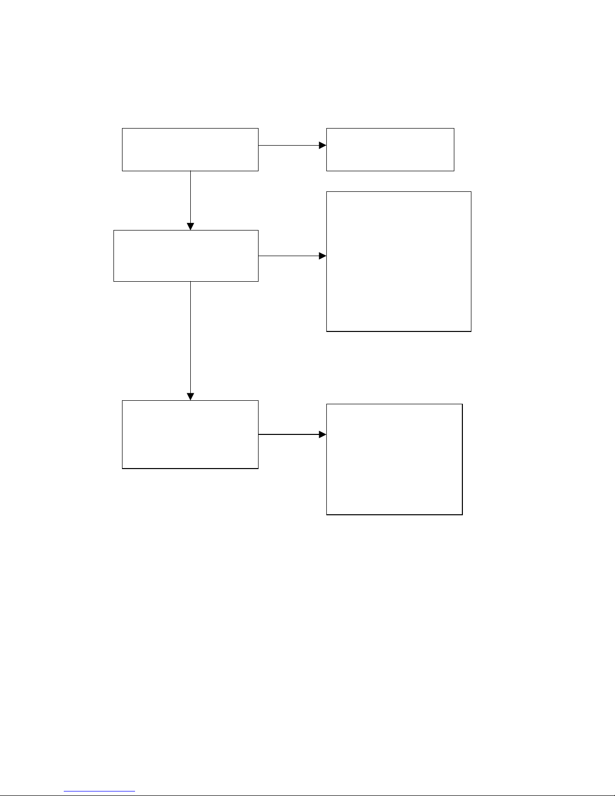
9.4 Using ATD to call, but “NO CARRIER” is displayed.
No
Capable of dialing an
outgoing call?
Yes
Does the “ CONNECT”
LED light up when
receiving an incoming call?
Yes
Does the PC indicate
RING?
No
No
Reconfirm settings on
the two previous
1. Please confirm the
telephone is functioning
properly on the other end.
2. Confirm Data bits; stop
bits, Parity and Flow
control type settings.
3. Reset service functions to
the same settings on both
calling side and called
side.
1. Refer to previous
section and check all
settings.
2. Reset after enters the
command of “ATQ0”.
3. The command “ATA”
can make TA to auto
answer mode.
D-LINK ISDN TA DMI-128ESU+
44
Page 45
9.5 Can not Accept Incoming Data Call
Can out going calls be
made?
Yes
Does the “LINE” LED
light up when receiving
an incoming call?
Yes
Does the PC indicate
RING?
No
No
No
Confirm settings on the
2nd and third section of
troubleshooting.
1. Please confirm the
telephone is
functioning properly
on the other end.
2. Confirm Data bits;
stop bits, Parity and
Flow control type
settings.
3. Reset service
functions to the same
settings on both
calling side and called
side.
1. Refer to previous
section and check all
settings.
2. Reset after enter the
command of “ATQ0”.
3. The command “ATA”
can make TA to auto
answer mode.
D-LINK ISDN TA DMI-128ESU+
45
Page 46
9.6 Unable to Accept Incoming Voice Call
Is there dial tone when
headset is removed from
the hook?
Is the incoming calls
being rejected?
Yes
No
No
Yes
Go through checks
outlined in section 2 and 3
of this trouble-shooting
manual. Contact the phone
manufacturer if the phone
still fails to work.
1. Please confirm the
telephone is functioning
properly on the other
end.
2. Confirm Data bits; stop
bits, Parity and Flow
control type settings.
3. Reset service functions
to the same settings on
both calling side and
called side.
4. Terminate “Call Screen”
function.
Is this analog port
connected to more than
one telephone and/or fax?
Yes
Only one telephone set or
one fax machine can be
connected to one analog
port. Please disconnect all
additional devices.
D-LINK ISDN TA DMI-128ESU+
46
Page 47
9.7 Can Not Use Call Waiting
Does incoming tone appear
during calls?
No
Confirm local switch
provides Call Waiting
Yes
Make sure that when
hang up or use the
“flash” key to switch
calls, the duration is
about one second.
D-LINK ISDN TA DMI-128ESU+
47
Page 48
9.8 Self Diagnostics
Power On Self-Diagnostic
The TA is installed with power-on self-diagnostic functions. After the power is switched
on, the TA will perform the following self-test diagnostics.
Item Description
ROM Inspect ROM‘s to CHECK ROM size
RAM Inspect RAM‘s read/write operations
Do not turn off power during self-diagnostic.
♦
If a problem occurs during self-diagnostic, the POWER LED will
♦
continue flashing after the test.
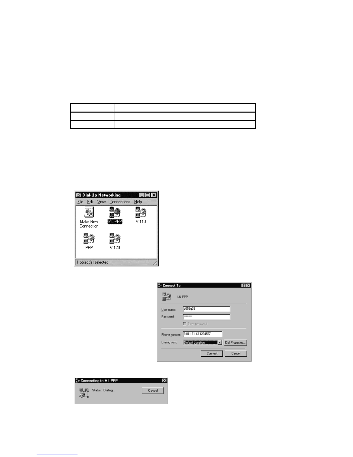
Before you test the ISDN TA, there are some things need to be noted as shown below:
2. Make sure the right User
name, Password and Dial-Up
number (i.e. Telephone
number provided by ISP) are
used and click the connect
button.
1. Select the correct transfer
protocol you are going to dial,
make sure that these models have
been set already. (See Chapter 5.6
for reference)
D-LINK ISDN TA DMI-128ESU+
The Dialog Box
3.
shows dialing the
connection.
48
Page 49
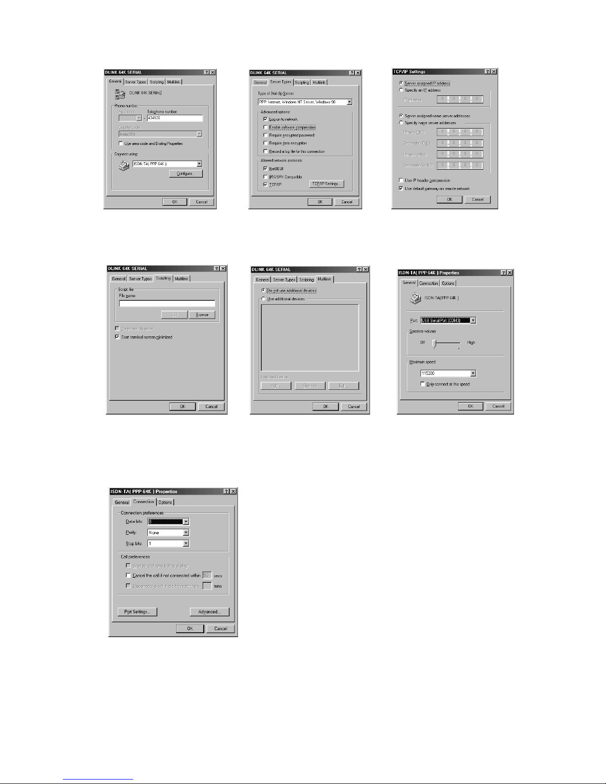
Ensure the following Properties in the Dial-Up Netwoking.
4.
Fig: 1 fig: 2 fig: 3
Fig: 4 fig: 5 fig: 6
Fig: 7
In fig 2-Uncheck Enable software
compression.
In fig 3- Uncheck
compression.
In fig 6- Select the correct port where ISDN
TA is installed.
Use IP header
D-LINK ISDN TA DMI-128ESU+
49
Page 50
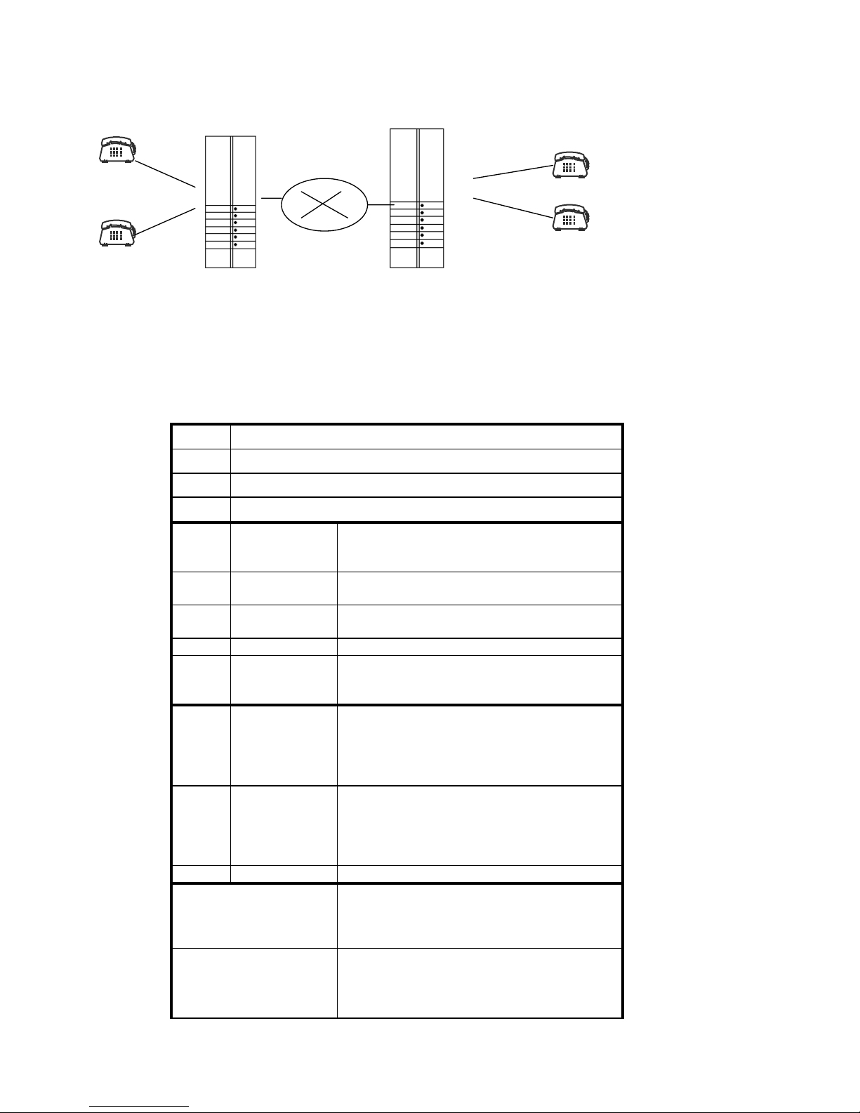
10. Supplementary Service Function
DMI-128ESU+ DMI 128 ESU+
ISDN
C
D
B
The supplementary services will require Analog phone having flash timing set to 600 msec.
(flash=600 msec). Check with your Telco (PTT) for supplementary service availability.
Follow the AT Command in Chapter 6 along with this procedure.
10.1 Definition
AT$CI1
AT$CS1
AT$CS2
AT$CS3
LIT
BT
DT
RBT
IRBT
IR
ICR
HT
Waiting first dial digit time
Flash signal recognition time
Set inner communication enable
No Network/Local supplementary service function provided
Only Network supplementary service function provided
Only Local supplementary service function provided
Local incoming
tone
Busy tone
Dial tone
Ring-back tone
Inner ring-back
tone
Inner ring
Incoming ring
Holding tone
♦ 400Hz tone
♦ 0.125sec on, 0.1sec off, 0.125sec on, 0.1sec off,
3.55sec off repeated
♦ 400Hz tone
♦ 0.5sec on, 0.5sec off continually
♦ 400Hz tone
♦ Continual
♦ Receive from Network ISDN switch
60ms on, 50ms off, 60ms on, 3250ms off,
♦
repeated
♦ 400 HZ tone
♦ 25Hz ring signal
♦ When TA detects an inner communication and
sends ring signal to TEL-A/B by clicking the
ringing relay
♦ Ringing period is same as IRBT
♦ 25Hz ring signal
♦ When TA accepts an incoming call and sends
ring signal to TEL-A/B/C by clicking the
ringing relay
Ringing period is 1sec on, 2sec off repeated
♦
♦ Send by Network ISDN switch
♦ After TEL-A/B off hook, TA sends DT to TEL-
A/B
♦ If after 25 seconds TA did not receive any
dialing digit, TA send BT to POTS-A/B
♦ TA detects Flash-Hook signal from TEL-A/B
♦ Flash timing to be set to 600 msec on POTS
A/B for correct operation.
D-LINK ISDN TA DMI-128ESU+
50
Page 51

On-Hook signal recognition
time
Ideal mode
Talk mode
♦ TA detects a Flash-Hook signal from TEL-A/B
♦ If Flash-Hook time >=2.2 sec then it is a correct
On-Hook signal
♦ On-hook, disconnected and no any event
occurred to the POTS interface
♦ Off-Hook and talking with only one other party
10.2 Making an Outgoing Call
Case No
To hear the PTT telephone line dial tone on lifting the telephone A or B OFF-HOOK, use the following
command in HyperTerminal. i.e. AT%A5=0.
To hear the ISDN TA’s internal dial tone on lifting the telephone A or B OFF-HOOK, use the following
command in HyperTerminal. i. e. AT%A5=1.
Representation
When A is in the idle mode
0
1. A off-hook
2. A hears TA’s DT
A dials the telephone number of C
3.
TA2 rings C (if C is in idle mode, TA2 sends ICR to C)
4.
5. A hears Network’s RBT
6. C off-hook (TA2 stops ICR)
A talks to C (A is in talk mode with C)
7.
When A at Case 0, step 3
1
1. If C is busy
A hears TA’s BT
2.
3. A on hook
4. A returns to idle mode
When A at Case 1, step 2
1.1
A flash
1.
A go to Case 0, step 2
2.
When A at Case 0, step 2/3/4/5/6
2
1. A on-hook
2. A is disconnected
A returns to the idle mode
3.
When A at Case 0, step 4
3
A flash
1.
2. TA2 stops to ring C
3. A go to Case 0, step 2
When A at Case 0, step 6/7
4
1. A flash
C is disconnect
2.
3. C hears Other TA’s BT
A go to Case 0, step 2
4.
When A at Case 0, step 7 (talk mode)
5
A on-hook
1.
C hears Other TA’s BT
2.
3. A is disconnected
A returns to idle mode
4.
When A at Case 0, step 7 (talk mode)
6
C on-hook
1.
C is disconnected
2.
A go to Case 1, step 2
3.
D-LINK ISDN TA DMI-128ESU+
51
Page 52

W
10.3 Making an Incoming Call
Case No Representation
When A is in idle mode
0
1. TA receives an incoming call to A
TA rings A (TA sends ICR to A)
2.
A off-hook
3.
4. A talks to the originated party (talk mode)
When A is in (1)
1
TA receives an incoming call to A
1.
TA reject the incoming call
2.
3. A still at (1) Outgoing call, Case 0, step 1/2/3 (A’s state is not
changed)
Outgoing call
, Case 0, step 1/2/3
10.4 Making an Inner Communication
. TEL-A calls TEL-B by dialing * * 0
. TEL-B calls TEL-A by dialing * * 0
To enable inner communication give the following command in HyperTerminal. i.e. AT%A5=1&W …(after
using this command, you will save the current inner communication settings even after powering OFF the TA)
10.5 Making a Local Call Waiting
Case No
Representation
When A is in talk mode with C
0
1. A Talks to C (occupy one B-ch for example B1-ch)
2. D calls A
3. A hears TA’s ICT
4. A flash
5. C holds (C hears
6. A talks to D (B2-ch, if C use B1-ch then D should use B2-ch)
7. A flash
8. D holds (D hears silent from TA)
9. A go to Case 0, step 1
LHT
from TA)
10.6 Making a Local Call Transfer
Case No
D-LINK ISDN TA DMI-128ESU+
Representation
When A is in talk mode with C
0
1. A talk to C
2. A flash +2
3. C hold (hears silent from TA)
4. A dial * * 0
5. TA rings B
6. B off-hook
7. B talks to C
8. A hears TA’s BT
9. A returns to idle mode
When A at Case 0, step 5
1
1. if B is busy (off-hook or talking with somebody)
2. A hears TA’s BT
3. A flash
4. A talks to C (A is in talk mode with C)
2
hen A at Case 1, step 2
1. A on hook
2. TA rings A
3. A off-hook
4. A talks to C (A is in talk mode with C)
52
Page 53

10.7 Making a Local 3 Party Conference
• Same operating sequence with network 3 party conference.
Case No
Representation
When A and D is in talk mode
0
1. A talks to D
2. A press flash key then press 1
3. D hears holding tone
4. A hears TA1’s dial tone
5. A calls C
6. C off-hook
7. A and C is in talk mode
8. A press flash then press 0
A, D, C are in 3 party conference
10.8 Making a Local Call Forwarding
Case No
Representation
1. Set AT$CF1 for local call forwarding
0
2. Set AT*CFG1 to enable global call forwarding
1. Set AT*CFA1 to enable call forwarding for A
2. Set AT*CFB1 to enable call forwarding for B
Set AT*CFG=xxxxxx for the global call forwarding number
3.
(If TA received an incoming call but without called party
number then this call is named global call)
4. Set AT*CFA=xxxxxx for A call forwarding number only
5. Set AT*CFB=xxxxxx for B call forwarding number only
When TA received an incoming global call
1
1. TA will inform network to forward this incoming call to the
number specified by AT*CFG=xxxxxx
(For example, if set AT*CFG= to D then D will be ringed)
Note:
If there is no B-ch available, then TA will reject the local
call forwarding. Calling party will hear BT.
When TA received an incoming call directly for A
2
1. TA will inform network to forward this incoming call to the
number specified by AT*CFA=xxxxxx
(For example, if set AT*CFA= to D then D will be ringed)
Note:
If there is no B-ch available, then TA will reject the local
call forwarding. Calling party will hear BT.
When TA received an incoming call directly for B
3
1. TA will inform network to forward this incoming call to the
number specified by AT*CFA=xxxxxx
(For example, if set AT*CFA= to D then D will be ringed)
Note:
If there is no B-ch available, then TA will reject the local
call forwarding. Calling party will hear BT.
D-LINK ISDN TA DMI-128ESU+
53
Page 54
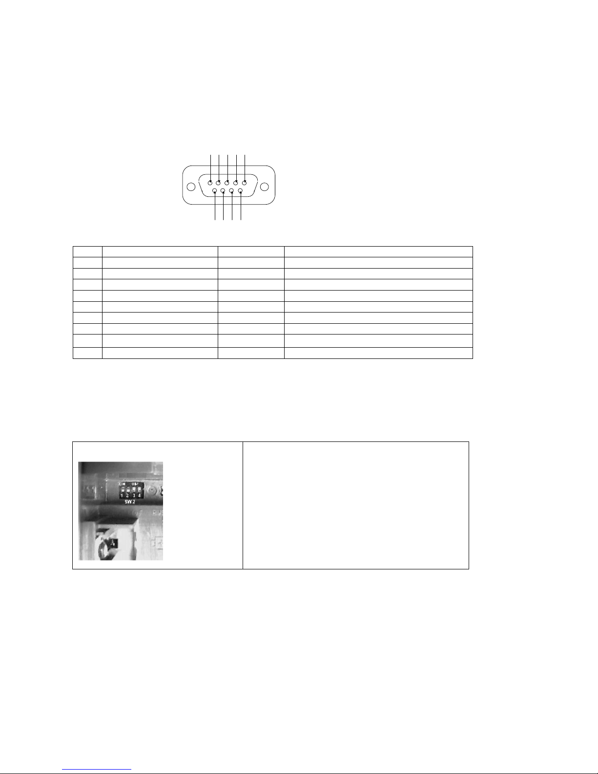
APPENDIX
APPENDIX 1 DCE 9Pin D Type Connector Definition
1235 4
6789
Pin Signal Name Direction Description
3 SD, Send Data
2 RD, Receive Data
7 RS, Request to Send
8 CS, Clear to Send
6 DR, Data Set Ready
5 SG, Signal Ground
1 CD, Carrier Detect
4 ER, Data Terminal Ready
9 CI, Ring Indication
Æ
Å
Æ
Å
Å
Å
Å
Æ
Å
DTE send data to TA
TA send data to DTE
DTE request to send data
TA inform DTE can to send data
TA is ready receiving command from DTE
TA signal ground (GND)
TA inform DTE that has a call incoming already
DTE is ready, it can working now
Incoming ring indication
Terminating Resistor Settings (DIP Switch inside Battery Compartment)
Switch SW2
DIP Switch 1,2 - ON (default) =100 ohm Terminating
Resistor
DIP Switch 1,2 - OFF =0 ohm Terminating
Resistor
DIP Switch 3 - OFF (default) =N.A Keep in OFF Mode
DIP Switch 4 - OFF (default) =N.A Keep in OFF Mode
The Terminating Resistor of 100 ohm should be set in the
DMI-128ESU+, when your NT1 is set to 100 ohms, in the
point-to-point connection, between NT1 and TA.
D-LINK ISDN TA DMI-128ESU+
54
Page 55

APPENDIX 2 Disconnect Cause Indication
Class No. Description
Normal
Event
Resource
Unavailable
Service or
option not
available
Service or
option not
implemented
Invalid
message
Protocol error
Inter-working 127 Inter-working, unspecified
001 Unassigned (unallocated) number
002 No route to specified transit network
003 No route to destination
006 Channel unacceptable
007 Call awarded and being delivered in an established channel
016 Normal call clearing
017 User busy
018 No user responding
019 User alerting no answer
021 Call rejected
026 Non-selected user clearing
027 Destination out of order
028 Incomplete number
029 Facility rejected
030 Response to STATUS ENQUIRY
031 Normal, unspecified
034 No circuit/channel available
038 Network out of order
041 Temporary failure
042 Switching equipment congestion
043 Access information discarded
044 Requested circuit/channel not available
047 Resource unavailable, unspecified
049 Unable to use QOS
050
057 Bearer capability no authorized
058 Bearer capability not presently available
063 Service or option not available
065 Bearer capability not implemented
066 Channel type not implemented
069 Requested facility not implemented
070 Only restricted digital information bearer capability is available
079 Service or option not implemented, unspecified
081 Invalid call reference value
082 Identified channel does not exist
083 A suspended call exists, but this call identity does not
Exist
085 No call suspended
086 Call having the requested call identity has been cleared
088 Incompatible destination
091 Invalid transit network selection
095 Invalid message, unspecified
096 Mandatory information element is missing
097 Message type non-existent or not implemented
098 Message not compatible with call state or message type non-existent
or not implemented
099 Information element non-existent or not implemented
100 Invalid information element contents
101 Message not compatible with call state
102 Recovery on time expiry
111 Protocol error, unspecified
D-LINK ISDN TA DMI-128ESU+
55
Page 56

APPENDIX 3 Specification
Rate
Type
S/T interface
Connection (To NT1)
Analog port
Data port
Protocol
• 2B +D Basic Rate (BRI)
External
•
• ITU-T I.430 S/T-interface
• 4-wire
• 2 x S/T-interface port
• AMI line coding
• RJ45 modular jack
• Terminating resistance selectable for 100 Ohm or none
• Point-to-multipoint, point to point.
• 2 x analog ports
• RJ11 modular jack
• ITU-T G.711 a-law
25Hz, 59Vrms ringing signal: 1-sec on, 2-sec off
•
• Tone Generation
• Dial tone: 400 +/- 20 Hz
• Busy tone
• Holding tone
• Incoming tone
• -59VDC
• DTMF dialing
• DTMF Caller ID
• 1 x data port
• DB - 9SUB male connector or USB for Windows 98/2000
Auto - baud detection
•
• DTE speed
• 1200/2400/4800/9600/19200/38400/57600/115200/230400 bps
• Communication speed
• Sync: 64000/128000 bps
• Async: 1200/2400/4800/9600/19200/38400 bps
• Hardware RTS/CTS flow control
• Software Xon/Xoff flow control
• 1 * USB port
• V.110
V.120
•
• PPP 64K
• ML-PPP 128K
• X.75
• X.25 on D
• Soft-Fax
• Channel bundling
• BACP/BOD
D-LINK ISDN TA DMI-128ESU+
56
Page 57

Switching
LED
Power
Maintenance
EMI
Operation
Humidity
Dimension
Weight
• Euro ISDN (EDSS1)
• Power: Power on indication
• CONNECT: connected to ISDN Network
• DTR: DTE ready
• TX/RX: Data transmitting/receiving
• LINE: ISDN Line is connected to TA
• 230VAC, 50-60 Hz, o/p: DC 5V 2.8A
• 6 x AA battery (Alkaline)
• Power on self-diagnostic
• Flash EPROM for software upgrade
• Minimum operation mode
Factory default setting
•
User profile saving in non-volatile memory
•
• CE EMI Class-2
• 0 to 40 degree C
10 to 95% RH
•
• 55mm(W) x170mm (D) x155mm (H)
• 0.8Kg
D-LINK ISDN TA DMI-128ESU+
57
Page 58

APPENDIX 4:REGISTRATION CARD
Print, type or use block letters.
Your name: Mr./Ms
Organization:
Your title at organization:
Telephone
_______________________________________
:
Organization's full address:
___________________________________________________________________________________________________________________________________
Country:
________________________________________________________________________________________________________________________
Date of purchase (Month/Day/Year):
(* Applies to adapters only)
Product was purchased from:
Reseller's name:
Telephone:
_______________________________________
Reseller's full address:
____________________________________________________________________________________________________________________________________
____________________________________________________________________________________________________________________________________
Answers to the following questions help us to support your product:
1.Where and how will the product primarily be used?
Home Office Travel Company Business Home Business Personal Use
2. How many employees work at installation site?
1 employee 2-9 10-49 50-99 100-499 500-999 1000 or more
3. What network protocol(s) does your organization use?
XNS/IPX TCP/IP DECnet Others
4. What network operating system(s) does your organization use?
D-Link LANsmart Novell NetWare NetWare Lite SCO Unix/Xenix PC NFS 3Com 3+Open
Banyan Vines DECnet Pathwork Windows NT Windows NTAS Windows '95
Others_________________________________________________________________________
5. What network management program does your organization use?
D-View HP OpenView/Windows HP OpenView/Unix SunNet Manager Novell NMS
NetView 6000 Others
6. What network medium/media does your organization use?
Fiber-optics Thick coax Ethernet Thin coax Ethernet 10BASE-T UTP/STP
100BASE-TX 100BASE-T4 100VGAnyLAN Others
7. What applications are used on your network?
Desktop publishing Spreadsheet Word processing CAD/CAM
Database management Accounting Others
8. What category best describes your company?
Aerospace Engineering Education Finance Hospital Legal
Insurance/Real Estate Manufacturing
Retail/Chainstore/Wholesale Government Transportation/Utilities/Communication VAR
System house/company Other
9. Would you recommend your D-Link product to a friend?
Yes No Don't know yet
10.Your comments on this product?
_____________________________________________________________________________
_____________________________________________________________________________
_________________________________________________________________________________________________________
________________________________________________
__________________________________________________________________________________________________
_______________________________________________________________________
Fax:
_______________________________________________________________________________________________
___________________________________________________________________________________
Product
Model
Product
Serial
No.
_________________________________________________________
Dept.
* Product
installed in type
of
computer (e.g.,
* Product
installed in
computer serial
No.
Compaq 486)
______________________________________________________________________________________________________________
________________________________________________________________________
Fax:
______________________________________________________________________________________________________
____________________________________________________________________________
____________________________________________________________________________________________________
_________________________________________________________
______________________________________________________________________
_______________________________________________________________________________________
D-LINK ISDN TA DMI-128ESU+
58
Page 59
D-LINK ISDN TA DMI-128ESU+
59
Page 60

Offices
AUSTRALIA D-LINK AUSTRALIA
Unit 16, 390 Eastern Valley Way, Roseville, NSW 2069, Australia
TEL: 61-2-9417-7100 FAX: 61-2-9417-1077
TOLL FREE: 1800-177-100 (Australia), 0800-900900 (New Zealand)
URL: www.dlink.com.au E-MAIL: [email protected], [email protected]
.au
CANADA D-LINK CANADA
#2180 Winston Park Drive, Oakville, Ontario, L6H 5W1 Canada
TEL: 1-905-829-5033 FAX: 1-905-829-5095 BBS: 1-965-279-8732 FREE CALL: 1-800-354-6522
URL: www.dlink.ca E-MAIL: [email protected] FTP: ftp.dlinknet.com
CHILE D-LINK SOUTH AMERICA
Isidora Goyeechea 2934 of 702, Las Condes, Santiago – Chile S.A.
TEL: 56-2-232-3185 FAX: 56-2-232-0923 URL: www.dlink.cl E-MAIL: [email protected], [email protected]
CHINA D-LINK CHINA
2F., Sigma Building, 49 Zhichun Road, Haidian District, 100080 Beijing, China
TEL: 86-10-88097777 FAX: 86-10-88096789
URL: www.dlink.com.cn
DENMARK D-LINK DENMARK
Naverland 2, DK-2600 Glostrup, Copenhagen, Denmark
TEL: 45-43-969040 FAX:45-43-424347 URL: www.dlink.dk
E-MAIL: [email protected]
EGYPT D-LINK MIDDLE EAST
7 Assem Ebn Sabet Street, Heliopolis Cairo, Egypt
TEL: 202-2456176 FAX: 202-2456192 URL: www.dlink-me.com
E-MAIL: [email protected], [email protected]
FRANCE D-LINK FRANCE
Le Florilege #2, Allee de la Fresnerie
78330 Fontenay le Fleury France
TEL: 33-1-302-38688 FAX: 33-1-3023-8689 URL: www.dlink-france.fr
E-MAIL: [email protected]
GERMANY D-LINK Central Europe/D-Link Deutschland GmbH
Schwalbacher Strasse 74
D-65760 Eschborn, Germany
TEL: 49-6196-77990 FAX: 49-6196-7799300
URL: www.dlink.de BBS: 49-(0) 6192-971199 (Analog) 49-(0) 6192-971198 (ISDN)
INFO LINE: 00800-7250-0000 (toll free) HELP LINE: 00800-7250-4000 (toll free)
REPAIR LINE: 00800-7250-8000 E-MAIL: [email protected]
INDIA D-LINK INDIA
Plot No.5, Kurla-Bandra Complex Road,
Off Cst Road, Santacruz (E), Bombay - 400 098 India
TEL: 91-22-26526696/26902210 FAX: 91-22-26528914 URL: www.dlink.co.in
E-MAIL: [email protected] ; [email protected]
ITALY D-LINK ITALIA
Via Nino Bonnet No. 6/b, 20154 Milano, Italy
TEL: 39-02-2900-0676 FAX: 39-02-2900-1723 URL: www.dlink.it
E-MAIL: [email protected]
JAPAN D-LINK JAPAN
10F, 8-8-15 Nishi-Gotanda, Shinagawa-ku, Tokyo 141, Japan
TEL: 81-3-5434-9678 FAX: 81-3-5434-9868 URL: www.d-link.co.jp
E-MAIL: [email protected]
RUSSIA D-LINK RUSSIA
Michurinski Prospekt 49, 117607 Moscow, Russia
TEL: 7-095-737-3389, 7-095-737-3492 FAX: 7-095-737-3390
URL: www.dlink.ru E-MAIL: [email protected]
SINGAPORE D-LINK INTERNATIONAL
1 International Business Park, #03-12 The Synergy, Singapore 609917
TEL: 65-774-6233 FAX: 65-774-6322
URL: www.dlink-intl.com E-MAIL: [email protected]
D-LINK ISDN TA DMI-128ESU+
60
Page 61

S. AFRICA D-LINK SOUTH AFRICA
102-106 Witchhazel Avenue, Einetein Park 2, Block B,
Highveld Technopark Centurion, South Africa
TEL: 27(0) 126652165 FAX: 27(0) 126652186
URL: www.d-link.co.za E-MAIL: [email protected]
SWEDEN D-LINK SWEDEN
P.O. Box 15036, S-167 15 Bromma Sweden
TEL: 46-(0) 8564-61900 FAX: 46-(0) 8564-61901 E-MAIL: [email protected]
URL: www.dlink.se
TAIWAN D-LINK TAIWAN
2F, No. 119 Pao-Chung Road, Hsin-Tien, Taipei, Taiwan,
TEL: 886-2-2910-2626 FAX: 886-2-2910-1515 URL: www.dlinktw.com.tw
E-MAIL: [email protected]
U.K. D-LINK EUROPE
4th Floor, Merit House, Edgware Road, Colindale, London, NW9 5AB, U.K.
TEL: 44-20-8731-5555 FAX: 44-20-8731-5511
URL: www.dlink.co.uk E-MAIL: [email protected]
U.S.A D-LINK U.S.A.
53 Discovery Drive, Irvine, CA 92618 USA
TEL: 1-949-788-0805 FAX: 1-949-753-7033 INFO LINE: 1-800-326-1688
BBS: 1-949-455-1779, 1-949-455-9616
URL: www.dlink.com E-MAIL: [email protected], [email protected]
D-LINK ISDN TA DMI-128ESU+
61
 Loading...