

Page 1

PC
PCMCIA
D-Link DMF-560TXD
DirectPort
Multifunction PC Card
User Manual
56K BPS
Page 2

USER MANUAL
DirectPort PC Card
First Edition (September, 1998)
Second Edition (May, 1999)
Document No. M-LF560MA-rev2.0
Printed in Taiwan
Page 3

FCC REGULATORY STATEMENTS
FCC Certification
10/100 Fast Ethernet + 56K Fax/Modem PC Card
FCC ID: MQ4PLM56
Made in Taiwan
The United States Federal Communication Commission (FCC) and
the Canadian Department of Communications have established
certain rules governing the use of modems and other electronic
equipment.
FCC Part 68 Registration
This high speed 10/100 Fast Ethernet + 56K FAX/MODEM PC
Card complies with FCC Part 68 rules, and the use of this modem
is subject to the following restrictions:
1. The FCC has established rules which permit this device to be
directly connected to the telephone network. Standardized jacks
are used for these connections. This equipment should not be
used on party lines or coin phones.
2. If this device is malfunctioning, it may also be causing harm to
the telephone network; this device should be disconnected until
the source of the problem can be determined and until repair has
been made. If this is not done, the telephone company may
temporarily disconnect service.
3. The telephone company may make changes in it's facilities,
equipment, operation and procedures; if such changes affect the
compatibility or use of this device, the telephone company is
required to give adequate notice of the situation with the FCC.
4. If the telephone company requests information on what
equipment is connected to their lines, inform them of:
a. The telephone number to which this unit is connected.
b. The Ringer Equivalence Number (REN).
c. The USOC jack required.
d. The FCC Registration number.
Items (b) and (d) are indicated on the label. The Ringer
Equivalence Number (REN) is used to determine how many
Page 4

devices can be connected to your telephone line. In most areas, the
sum of the REN's of all the devices on any one line should not
exceed 5.0. If too many devices are attached, they may not ring
properly.
FCC Part 15 Registration
This device complies with Part 15 of FCC rules. Operation is
subject to the following two conditions:
1) This device may not cause harmful interface, and
2) This device must accept any interface received, including
interface that may cause undesired operation.
This equipment has been tested and found to comply with the
limits for a Class B digital device, pursuant to Part 15 of the FCC
Rules. These limits are designed to provide reasonable protection
against harmful interference in a residential installation. This
equipment generates, uses and can radiate radio frequency energy,
and if not installed and used in accordance with the instructions,
may cause harmful interference to radio communications.
However, there is no guarantee that interference will not occur in a
particular installation. If this equipment does cause harmful
interference to radio or television reception, which can be
determined by turning off and on, the user is encouraged to try to
correct the interference by one or more of the following measures:
(1) Reorient or relocate the receiving antenna.
(a) Increase the distance between the equipment and
receiver
(b) Connect the equipment into an outlet on a circuit
different from that to which the receiver is connected.
(2) Consult an experienced radio/TV technician for help.
Page 5

TABLE OF CONTENTS
1. INTRODUCTION
1.1 ABOUT THIS MANUAL
1.2 ABOUT THIS PRODUCT
1.2.1 SPECIFICATIONS
1.2.2 FEATURES
1.3 SYSTEM REQUIREMENTS
1.4 CONTENTS INCLUDED IN THE PACKAGE
2. INSTALLATION
2.1 HARDWARE INSTALLATION
2.2 INSTALLING THE SOFTWARE
2.2.1 NOVELL NETWARE
2.2.2 MICROSOFT LAN MANAGER
2.2.3 PACKET DRIVER
2.2.4 WINDOWS FOR WORKGROUPS 3.11
2.2.5 WINDOWS NT 3.51 & 4.0
2.2.6 WINDOWS 95,WINDOWS 98
2.2.7 ARTISOFT LANTASTIC 6.0
3. MODEM BASICS
3.1 UNDERSTANDING AT COMMANDS
3.2 DIALING & ANSWERING TECHNIQUES
4. DRIVERS INFORMATION
4.1 NOTES for NDIS DRIVER
4.2 NOTES for PACKET DRIVER
4.3 NOTES for WINDOWS WORKGROUPS
5. QUESTIONS & ANSWERS
6. APPENDIX A: NDIS2 & ODI DRIVERS
FOR WFW 3.11
Page 6

7. APPENDIX B: UNINSTALLATION THE
DIRECTPORT IN WIN 98/95
8. APPENDIX C: AT COMMAND QUICK
REFERENCE
9. APPENDIX D: S-REGISTERS QUICK
REFERENCE
Page 7

- 1 -
1. INTRODUCTION
1.1. ABOUT THIS MANUAL
This manual will explain how to install and use your
DMF-560TXD DirectPort PC Card
1.2. ABOUT THIS PRODUCT
Your DirectPort PC Card is a multifunction
communication device that lets you perform multiple
communication tasks at the same time:
(1) transmit and receive data up to 56,000 bps
(2) send and receive FAXes from computers or
FAX machines
(3) connect to an 10/100 Fast Ethernet LAN
And it uses only one PCMCIA socket while it can
provide the functions listed above.
This PC Card is a credit-card-size Type II PCMCIA
adapter that complies with the PCMCIA 2.1 and
JEIDA 4.1 standards and works with computers that
incorporate a compatible interface.
It is Bell, ITU-T (formerly CCITT) and Hayes AT
commands compatible, allowing it to be used
worldwide with today's popular communication
software programs. You will be able to send and
receive faxes with any Group 3 fax machine. Using
standard phone lines and 10/100 Fast Ethernet, the
data communication functions of the 10/100 Fast
Ethernet + 56K Fax/Modem PC Card will enable you
Page 8

- 2 -
to successfully access to the servers on 10/100 Fast
Ethernet LAN and hook up to the Internet, transmit
E-Mail, send and receive information and
communicate with other PCs, Bulletin Board Services
(BBS) or on-line computer networks such as
CompuServe and America On line.
1.2.1. Specifications
PC Card Interface
PCMCIA Type II.
Dimension
3.37” X 2.128” X 0.197” or
85.6 mm X 54 mm X 5 mm
Weight
60 g
Power
+5V ±5%
Network
IEEE 802.3 10BaseT, 10Mbps.
IEEE 802.3u 100BaseTX, 100Mbps.
NE2000 compatible.
Modem
V.90, K56flex 56Kbps, V.34+ 33.6Kbps, V.34
28.8Kbps, V.32bis 14.4Kbps.
V.42bis/V.42, MNP 2-5 data compression and
error correction.
AT command set.
Fax
Group 3, V.17 14400bps, V.29 9600bps
Fax Service Class 1 compliant.
Modem COM Port
COM2, COM3, COM4
IRQ
3, 4, 5, 7, 9, 10, 11, 12, 15
I/O Address
220, 300, 320, 340
Page 9

- 3 -
1.2.2. Features
1.
Compatible with most notebook computers and
PCMCIA Card and Socket Service drivers.
2. Integrated PC Card
3. Easy to install and play.
4. Support most of the popular Network Operating
Systems.
5. Include popular 56K Fax/Modem
communication programs.
6. Hot swappable.
7. Feature concurrent use of 10/100 Fast Ethernet
LAN and 56K Fax/Modem.
8. NE2000 compatible.
1.3. SYSTEM REQUIREMENTS
• An IBM compatible PC or notebook computer with
386SX or faster processor
• At least one type II PCMCIA socket
• PCMCIA release 2.1 compliant Card Services and
Socket Services
• Drivers and utilities provided with this product
• Driver software loaded on your PC
• Data and/or fax communications software.
1.4. CONTENTS INCLUDED IN THE
PACKAGE
• DMF-560TXD DirectPort PC Card
• RJ 11 Phone Cable
• Quick Installation Guide
Page 10

- 4 -
• Driver Diskettes for PC and Apple/Macnitosh
• Manual Diskette
• Windows-based 56K Fax/Modem application
program (CD-ROM)
Page 11
- 5 -
2. INSTALLATION
This chapter describes how to install your DirectPort
multifunction PC Card. Installation procedures also
cover many popular Network Operating Systems.
2.1. HARDWARE INSTALLATION
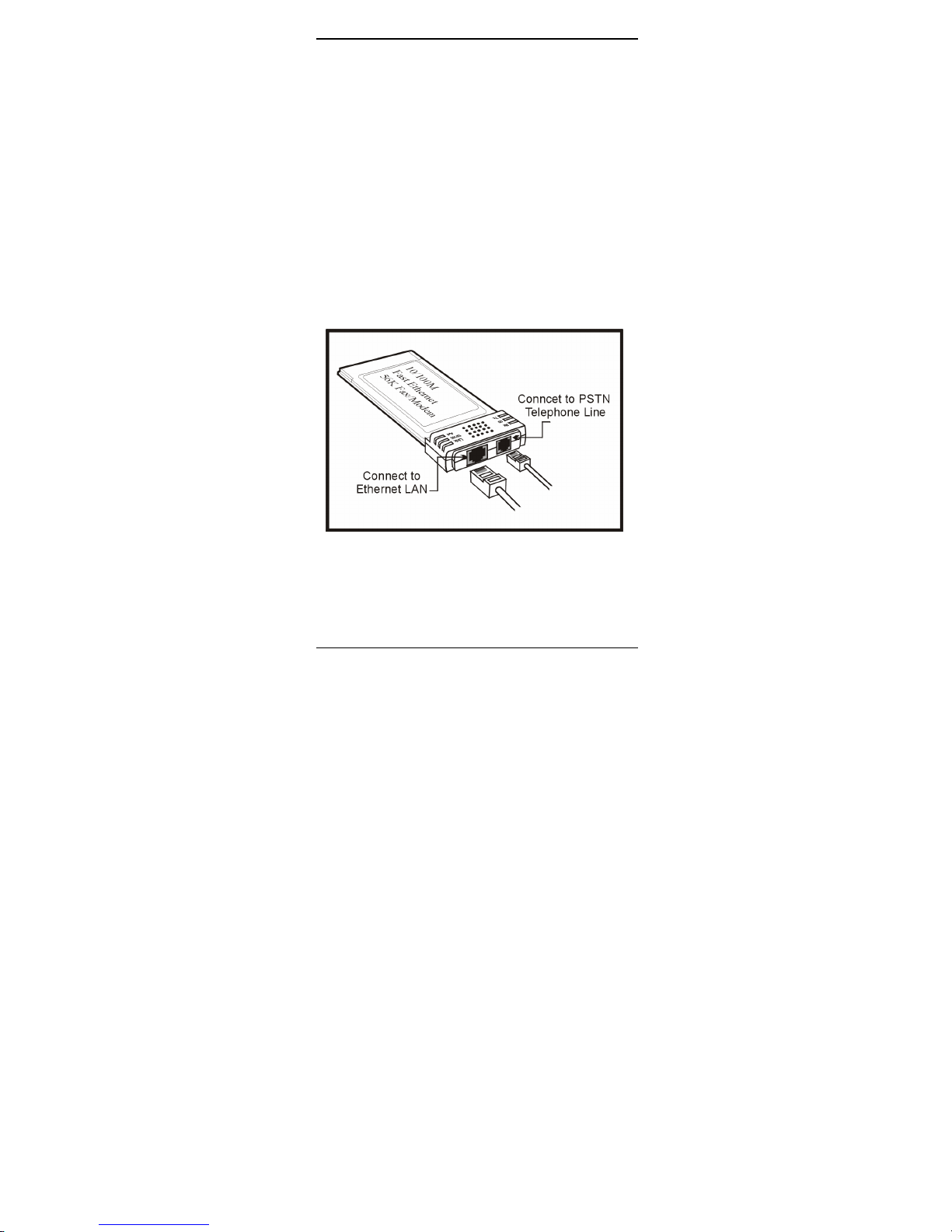
1. Hold the card label up and insert the card into the
computer's PCMCIA slot with the 68 pin
connector facing the computer.
2. Connect the RJ-45 (8-pin) plug to the LAN and
the RJ-11 (6-pin) plug to the telephone wall
outlet.
2.2. INSTALLING THE SOFTWARE
Page 12
- 6 -
For Non-Windows 95/98 & Non-Windows NT
System
Plug the driver diskette into the floppy drive and set
the current drive to the floppy drive (A:\). Then run
INSTALL to install the dirver.
2.2.1. Novell Netware Installation
Follow the steps bellow to complete the Novell
Netware installations.
1.Run installation program INSTALL.EXE in the
driver disk (for example, A:\INSTALL).
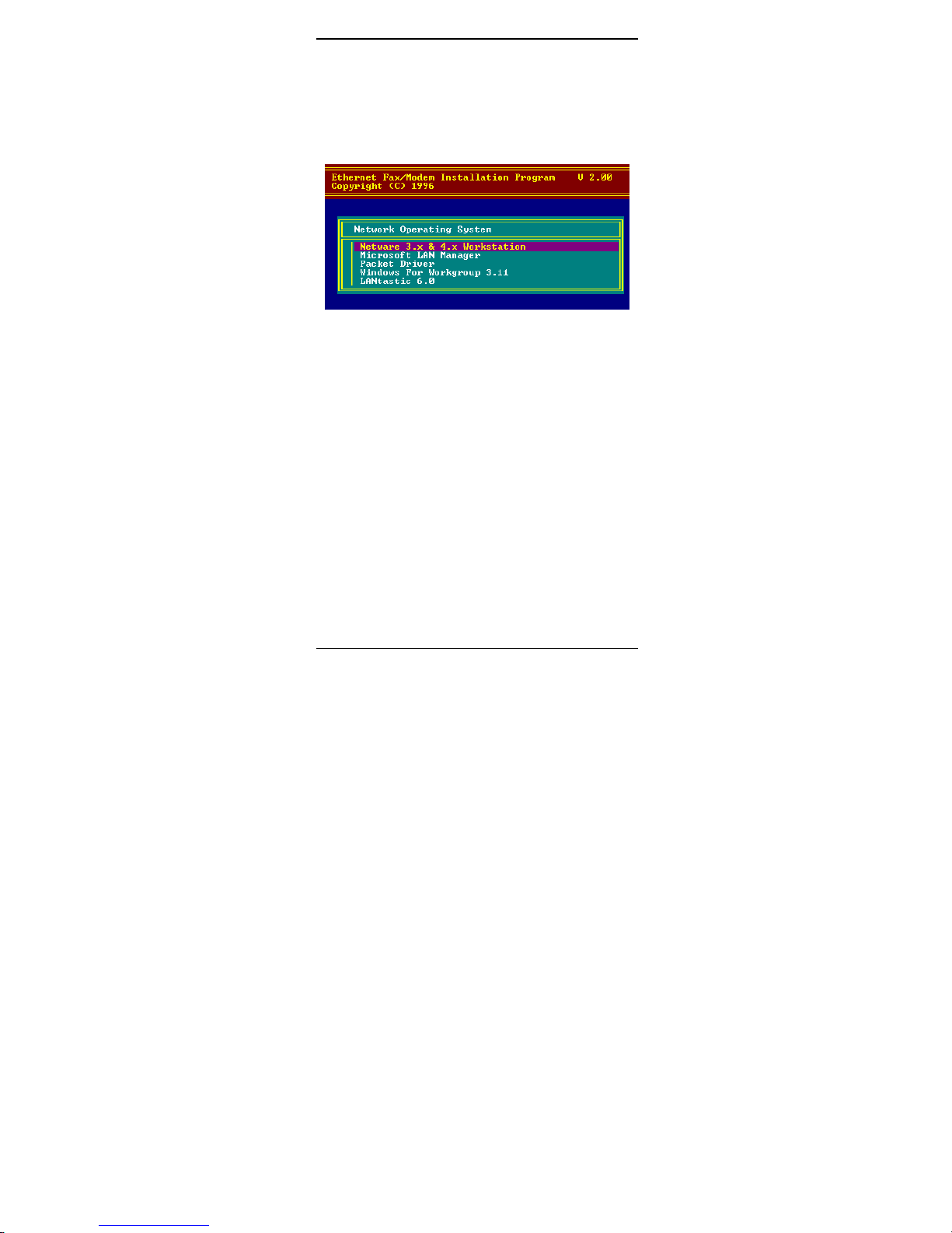
2.Select Netware 3.x and 4.x Workstation in the
installation program dialog box.
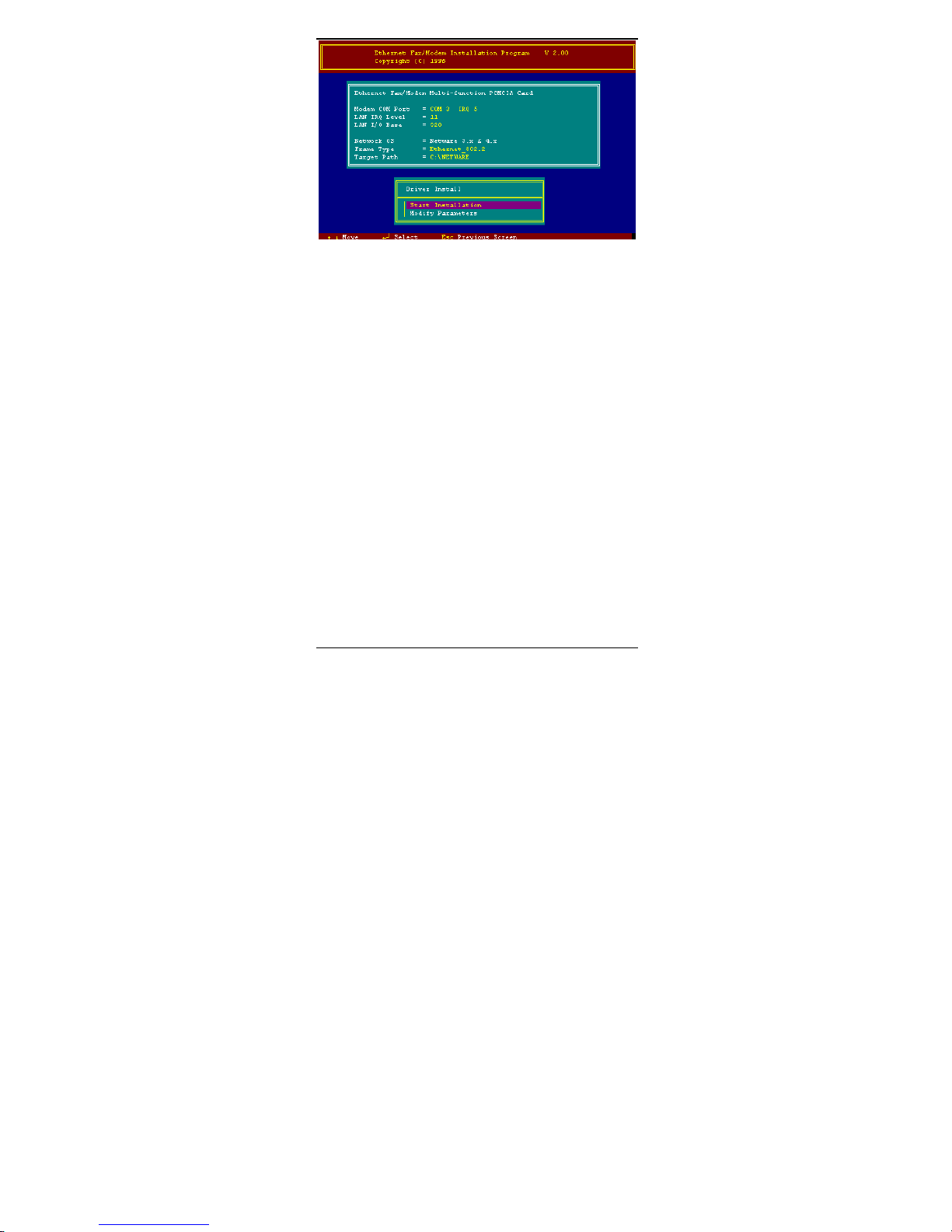
3.Check the card settings. If current settings are
correct, select Start Installation and go to step 5.
Otherwise, select Modify Parameters to change
settings.
4.Select the appropriate values then press Enter.
When you are finished, press OK to exit.
Page 13
- 7 -
5.Installation program starts installing drivers and
modifying AUTOEXEC.BAT and NET.CFG.
Select Yes then press Enter to modify the files.
6. Now, the installation is completed.
7. Restart your computer to make Netware
connections.
To install the ODI driver manually, follow the
instructions below:
1.Copy the file
\NETWARE\LM28ODI.COM
\NETWARE\NET.CFG
and the file
\ENABLER\CARDEN.EXE
\ENABLER\LMVXD.386
from the driver disk to your local hard disk.
2.Using text editor to edit the NET.CFG for setting
the frame type. The frame type default is set to
802.3 for Netware 3.11 server and 802.2 for
Netware 3.12 and 4.x servers. The frame type set in
NET.CFG must match that set in Netware servers.
3.Using following format to create a startup batch file
Page 14

- 8 -
CARDEN /IOP=nnn /IRQ=nnn /COM=n /MIR=n
LSL ;Link Support Layer Module
;provided by Novell
LM28ODI ;Hardware Specific Module
IPXODI ;IPX Protocol Stack Module
;provided by Novell
NETx ;Shell Support Module provided by
;Novell
LOGIN
2.2.2. MS LAN Manager Installation
1.Cast a look at the README.TXT in the \NDIS2
directory in the driver disk. Before installing the
drivers, please ensure that the Microsoft LAN
Manager has been installed in the target path. The
installation program will check and modify the
PROTOCOL.INI file for LAN Manager.
2.Run INSTALL.EXE in the root of driver diskette
(A:\INSTALL).
3.Select Microsoft LAN Manager from the menu
screen.
4.Check the card settings. If current settings are
correct, select Start Installation and go to step 5.
Otherwise, select Modify Parameters to change
settings.
5.Select the appropriate values then press Enter.
When you are finished, press OK to exit.
6.Installation program starts installing drivers and
modifying CONFIG.SYS and PROTOCOL.INI
Select Yes then press Enter to modify the files.
7.Now, the installation is completed.
8.Reboot the computer to load driver and start LAN
Manager.
Example of PROTOCOL.INI:
Page 15

- 9 -
[PROTMAN]
DRIVERNAME = PROTMAN$
DYNAMIC = YES
PRIORITY = NETBEUI
[NETBEUI_XIF]
Drivername = netbeui$
SESSIONS = 6
NCBS = 12
BINDINGS = "LMNDIS_NIF"
LANABASE = 0
[LMNDIS_NIF]
; protocol.ini session for multifunction
LAN/MODEM driver.
IOADDRESS = 0x320
INTERRUPT = 11
DRIVERNAME = LMNDIS$
2.2.3. Packet Driver Installation
1.Run INSTALL.EXE file in the driver diskette
(A:\INSTALL).
2.Select Packet Driver from the menu screen.
3.Check the card settings. If current settings are
correct, select Start Installation and go to step 5.
Otherwise, select Modify Parameters to change
settings.
4.Select the appropriate values then press Enter.
When you are finished, press OK to exit.
5.Installation program starts installing drivers and
modifying AUTOEXEC.BAT. Select Yes then
press Enter to modify the files.
6.Now, the installation is completed.
7.Reboot the computer to load driver.
Page 16

- 10 -
2.2.4. Windows for Workgroups 3.11
Installation
1. Run INSTALL.EXE in root directory on the
driver disk.
2. Select Windows for Workgroup in Network
Operating System screen.
3. If current settings are accepted, select Start
Installation and go to step 13. Otherwise, select
Modify Parameters to make modifications.
4. Move cursor to the setting you want to make a
change for then press Enter to select a fit value.
When the configuration is accepted, press Enter
on the OK field to exit the screen and go back to
step 3.
5. Select NDIS Server (LAN Manager,...) as the
network server that you will attach to then press
Enter.
6. Installation program starts installing drivers and
modifying AUTOEXEC.BAT. Select Yes then
press Enter to modify the files.
7. Run Windows for Workgroups and click
Network Setup icon in Network group.
8. In Network Settings dialog box, click
Networks... button to select the network
operating system.
9. In Networks dialog box, check the radio button
before Install Microsoft Windows Network
and No Additional Network. Press OK to go
back the Network Settings screen.
10. Click Drivers... button to select network driver.
11. From Network Drivers dialog box, press Add
Adapter... button to enter Add Network
Adapter dialog box. Select Unlisted or
Updated Network Adapter and press OK.
12. Windows will prompt a Install Driver dialog
Page 17

- 11 -
box; put the driver diskette into floppy drive
then press OK.
13. Select Enhanced mode NDIS3 for.... then press
OK.
14. Follow Windows instructions to complete the
installation and exit Windows
15. Reboot the computer to run with WFW 3.11.
2.2.5. Windows NT 3.51 & NT 4.0
Installation
Getting Start for Windows NT3.51
1. Run Windows NT 3.51
2. Login with a full access level , i.e.
ADMINISTRATOR
3. Remove all existing network support
-- open Program Manager Main group
Control Panel Network
-- remove all existing network components
Note: remove all adapters first, then servers,
then workstations, etc.
4. Remove all serial port support
-- open Program Manager Main group
Control Panel Ports
-- remove all the COM port devices
Note: If problems occur during removing the
COM ports, check if the NT has been
updated to the lastest release from Microsoft.
-- after all serial port devices are removed, press
Close
Add PCMCIA to Your Laptop
Page 18

- 12 -
1. Open Program Manager Main group
Control Panel Devices
2. Select PCMCIA
3. Press STARTUP
4. Select BOOT, then press OK
5. When all PCMCIA adapters are added, press
Close and restart Windows NT
Check Event Viewer when system reboots. Ask your
laptop dealer for help if any problems occur during
the pre-installation.
Installation in NT 3.51
1. Insert your DirectPort PC Card into one of the
PCMCIA slots
2. Run Windows NT
3. Login with a full access level i.e.
ADMINISTRATOR
4. Open Program Manager Main group
Control Panel Network
5. Press YES to install network components
6. Enter the correct path for NT installation media (
CD-ROM). For example, D:\i386.
7. Press ”Do not detect for the network adapter”
8. Open the Network Adapter Card selection box
9. Select <OTHER> REQUIRES DISK FROM
MANUFACTURER
10. Click CONTINUE button
11. Insert the driver disk into floppy disk drive, then
enter the correct path (A:\).
12. Take a choice for the 10/100 Fast Ethernet + 56K
Fax/Modem PC Card then press OK.
13. A dialog box will be poped up for the driver
settings change.
Page 19

- 13 -
14. Give appropriate system resources to the your
DirectPort PC Card, the settings must be unique
for this device. Resources Recommendation
I/O Base I/O:300. Possible alternative:
220, 320, 340
Interrupt
(IRQ)
IRQ:5. If your laptop is equipped
with multimedia devices, a
higher interrupt (IRQ:11) may be
needed.
Base Memory D000. Possible alternative: D800
COM Port COM2 to COM4. Select one of
the COM port that is not in use
by other communication devices.
15. When all settings are completed, press OK
Windows NT will load network and grant
configurations for
-NWLink
-TCP/IP
-Netbeui
Typically the configurations are unique for
each network. Ask your network administrator
for help if you want to change them.
16. Once all network softwares are well loaded, press
OK. The configuration and bindings for the PC
Card might be confirmed. Answer the questions
accordingly.
17. Connect to your network using the provided
10/100 Fast Ethernet RJ-45 jack.
18. Reboot the system.
Getting Start for Windows NT4.0
1. Remove all existing PC Cards from the system.
2. Run Windows NT 4.0
Page 20

- 14 -
3. Login with a full access level i.e.
ADMINISTRATOR
4. Remove all existing network support from
MY COMPUTER CONTROL PANEL
NETWORK ADAPTERS
5. Press CLOSE after all network components are
removed.
6. Remove all serial port devices in
MY COMPUTER CONTROL PANEL
PORTS
7. Press CLOSE after all serial port devices are
removed.
Installation in NT 4.0
1. Insert your DirectPort PC Card into one of the
PCMCIA Slots
2. Start Windows NT 4.0
3. Login with a full access level
ADMINISTRATOR
4. Open MY COMPUTER CONTROL
PANEL NETWORK.
If Network has not been installed,
♦ select YES to start Network installation,
♦ press Next and press SELECT FROM LIST
button, then press HAVE DISK button,
♦ insert the driver disk into drive floppy disk drive,
then enter the correct path.
♦ select the only one choice for the 10/100 Fast
Ethernet + 56K Fax/Modem PC Card, then press
OK and NEXT
♦ Windows NT 4.0 will grant configurations for
-- TCP/IP
-- NWLink IPX/SPX
-- NetBEUI
Page 21

- 15 -
...
These configurations are unique for each
network. If you want to change them, ask your
network administrator for help.
♦ Press Next twice to use default NETWORK
SERVICES settings
♦ Enter the correct path for NT 4.0 system source
files.
♦ A dialog box will pop up. Give appropriate
system resources to the DirectPort PC Card; the
settings must be unique for this device. Refer to
resources Recommendation” for NT 3.51 details
♦ Press NEXT twice. Enter COMPUTER NAME
then press NEXT
♦ Press FINISH
If Network has been installed
♦ Select ADAPTERS
♦ Press ADD to add network adapters
♦ Press HAVE DISK button
♦ Insert your DirectPort PC Card driver disk into
floppy disk drive
♦ Enter the correct path for Windows NT 4.0
drivers then press OK.
♦ A dialog box will pop up. Give appropriate
system resources to the DirectPort PC Card; the
settings must be unique for this device. Refer to
”Resources Recommendation” for NT 3.51
details
♦ Press OK when all setting are completed.
♦ Press CLOSE to complete NETWORK setting
♦ Reboot Windows NT.
Modem configuration for NT 4.0
1. Open MY COMPUTER CONTROL PANEL
Page 22

- 16 -
MODEMS
2. Using default settings and press NEXT
3. System should have detected your LANmodem
PC Card, and enter the Modem Manufactures
& Models list screen.
4. Press FINISH and then CLOSE to complete
modem setting.
5. Reboot the system.
6. The installations for both LAN and Modem are
completed.
2.2.6. Windows 98/95 Installation
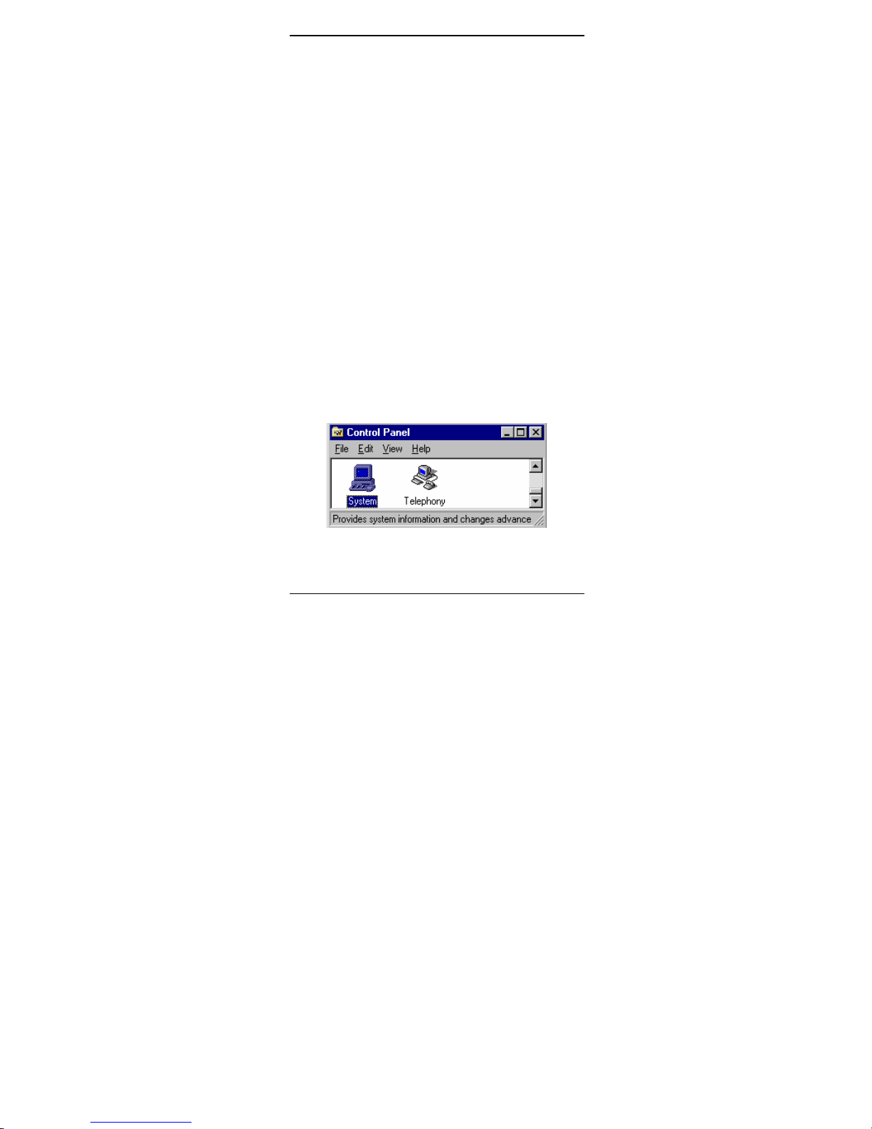
1.Assume that the PCMCIA card reader and drivers
have been loaded and well functioning. The System
Icon in the Control Panel can report on its
functionality. If not, check your computer dealer
for technical support.
2.Insert your DirectPort PC Card into PCMCIA slot.
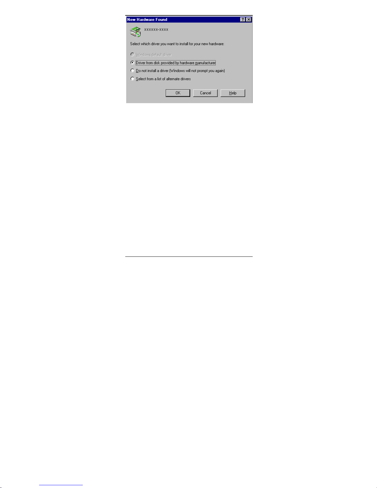
Windows 95/98 will prompt New Hardware
Found dialog box. In New Hardware Found
dialog box, select Driver from disk provided by
hardware manufacturer.
Page 23
- 17 -
3.Enter the correct path, i.e. :\”, then insert the
driver disk. The driver will be installed
automatically, and system may ask for the Windows
95/98 installation CD/disks to update the existing
files or drivers. After the update, system will reboot
automatically.
4.For the first time installation, click Network icon in
Control Panel to correctly add Protocols, Client
and Service according to your application
requirements.
5.Reboot the machine and the card will fully function.
2.2.7. Artisoft Lantastic 6.0 Installation
1.Install LANTASTIC 6.0 first.
2.Run INSTALL.EXE in the driver disk root
directory.
3.Select LANTASTIC 6.0 in Network Operating
System screen then enter Driver Install screen.
Page 24

- 18 -
4.If current settings are correct, select Start
Installation and go to step 6. Otherwise, select
Modify Parameters to make changes.
5.Move cursor to each field you want to make
modification and press Enter to set correct value.
Then press Enter on the OK.
6.Installation program starts copying drivers and
modifying CONFIG.SYS, PROTOCOL.INI, and
STARTNET.BAT.
7.Reboot the computer to have the driver take effect.
Page 25

- 19 -
3. MODEM BASICS
This chapter covers the basic commands and
techniques involved in modem operation. In many
cases, this is the only information you will need in
order to get your DirectPort PC Card up and running
with communication software, and to start making
connections with your PC Card.
3.1 Understanding AT Commands
The DirectPort PC Card communicates
asynchronously with computers using AT commands.
AT commands are used to configure and control the
PC Card. Commands are usually sent to the modem in
way of communication software, but can also be
entered manually with the computer keyboard.
Command statements must be written in a specific
form in order for the DirectPort PC Card to
recognize them. A command statement always begins
with the letters AT or at. It is then followed by one or
more commands and the <Enter> key.
AT commands can only be issued when the
DirectPort PC Card is in ”Command mode” or ”offline.” Once the PC Card has established a connection
with another modem, it is said to be ”on-line” or in
”Data mode.” In this mode, the characters sent to the
Ethenet + 56K Fax/Modem PC Card by your
computer are transmitted to the remote modem rather
than being interpreted by the PC Card as commands.
Using the Windows 95/98 Hyper Terminal Program
To issue an AT command statement, you first need to
run a communication program such as the Microsoft
Page 26

- 20 -
Windows ”Hyper Terminal” program. This program
provides a simple method to manually enter AT
commands so you can do things such as: store phone
numbers you commonly connect to.
Once the DirectPort PC Card is connected to your
computer serial port and telephone line, open the
Windows 95/98 ”Accessories” program group, and
open the Hyper Terminal Program. The program will
prompt you for a name and icon to use for your new
connection. Type the name Test Connection then
press <Enter>.
Next, you will be prompted for country information,
area code, phone number, and the device used to
make the connection. For this test purpose, do not
enter a phone number; simply choose the COM port
your DirectPort is connected to from the ”Connect
Using” list. Click ”OK” when finished.
The next window sets the COM port settings. The
settings used for the Comet should be as follows:
Bits per second: 115200
Data bits: 8
Parity: None
Stop bits: 1
Flow Control: Hardware
Click ”OK” when finished. After you have done this,
save your new connection by selecting ”Save” from
the ”File” menu then click ”OK.” A new connection
icon will be added to your Hyper Terminal folder.
You are now ready to start entering AT commands.
In the terminal window, type:
Page 27

- 21 -
AT<Enter>
LANmodem responds
OK
This confirms that the modem and your computer are
communicating correctly.
To test the telephone line connection, issue the
manual answer command. Type: ATA<Enter>
The LANmodem will pick up the phone line, and try
to communicate. Normally, this command is only
used to answer an incoming call made from another
modem. Thus the high pitched noise you will hear
from the speaker. To abort the operation, press any
key, or select ”Disconnect” from the menu.
3.2 Dialing and Answering Techniques
Depending on what communications software you use
to make modem connections, you may not have much
control of how the modem dials the telephone
number. This section shows some useful examples of
the AT commands used for dialing and answering
operations. The command characters specific to each
function are shown in bold type.
Dialing using the ATD Command
Touch Tone Dialing: ATDT 555 1212
Pulse Dialing: ATDP 555 1212
Tone and Pulse Dialing: ATDP 555 1212 WT 24
Pause During Dialing: ATDT 9,,555 1212
Auto-Answer and Hook Controls
Enabling Auto-Answer: ATS0=n
Note: In this example, n is a number from 1 to
255 that corresponds to the number of
rings after which your modem answers an
Page 28

- 22 -
incoming call.
Disabling Auto-Answer: ATS0=0
Manually Answering a Call: ATA
Take modem off-hook: ATH1
Hang up modem (on-hook): ATH0
Manually Disconnecting a Call: +++ATH
Page 29

- 23 -
4. DRIVERS INFORMATION
4.1. Notes for NDIS Driver
The following are examples of CONFIG.SYS file and
AUTOEXEC.BAT for loading System Soft Card
Services and NDIS2 driver:
Examples of CONFIG.SYS file:
device=c:\cardsoft \ss365sl.exe
device=c:\cardsoft \cs.exe
device=c:\cardsoft \csalloc.exe c:\cardsoft\csalloc.ini
device=c:\lanman.dos\drivers\10/100 Fast
Ethernet\lm28\carden.exe /iop=nnn /irq=n /com=n
/mir=n
device=c:\cardsoft \cardid.exe
device=c:\lanman.dos\deivers\protman.dos /i:c:\lanman.dos
device=c:\lanman.dos\drivers\10/100 Fast
Ethernet\lm28\lmndis.dos
Examples of partial AUTOEXEC.BAT file:
set path= c:\lanman.dos\netprog;%path%
net start workstation
load netbeui
The 10/100 Fast Ethernet function configuration
information for the DOS NDIS driver is contained in
the PROTOCOL.INI file. To make allowances for
passing the requested modem COM port (1,2,3,4) to
the driver, there has been another field added. The
section of the PROTOCOL.INI file that contains
configuration information for this card must begin
with [LMNDIS_NIF]. The valid entries in the file are
listed below:
Page 30

- 24 -
[LMNDIS_NIF]
DRIVERNAME - LMNDIS$
This line must always be presend
IOADDRESS - value
where value is one of the following address:
0x300, 0x320, 0x340, 0x360.
The leading 0x for the hex notation is required.
To have Card Services select the address base from
it's pool of available address then use a value of 0.
INTERRUPT - value
where values is one of the following interrupts:
3, 4, 5, 7, 9, 10, 11, 12, 15.
To have Card Services select an available interrupt
resource then place a value of 0 at this location.
4.2. Notes for Packet Driver
The following are examples of CONFIG.SYS file for
loading System Soft Card Services and packet driver:
Examples of partial CONFIG.SYS file:
device=c:\cardsoft\ss365sl.exe
device=c:\cardsoft\cs.exe
device=c:\cardsoft\csalloc.exe c:\cardsoft\csalloc.ini
device=c:\tcpip\carden.exe /iop=nnn /irq=n /com=n /mir=n
device=c:\cardsoft\cardid.exe
device=c:\tcpip\lmpd.com
4.3. Notes for Windows For
Workgroups
After installation of the multi-function PCMCIA card
drivers, the system will automatically update both
Page 31

- 25 -
CONFIG.SYS and AUTOEXEC.BAT for you so that
the driver will be loaded upon system start up. When
modifying the two files, the system will make copies
named CONFIG.ABO and AUTOEXEC.ABO in the
system's directory. If the driver of PC Card is not
successfully loaded, replace the two *.ABO file for
related file and try to start the system again.
The following are examples of CONFIG.SYS and
AUTOEXEC.BAT for loading System Soft Card
Services and drivers for Windows for Workgroups:
Examples of CONFIG.SYS file:
device=c:\cardsoft\ss365sl.exe
device=c:\cardsoft\cs.exe
device=c:\cardsoft\csalloc.exe c:\cardsoft\csalloc.ini
device=c:\wfw311\carden.exe /iop=nnn /irq=n /com=n
/mir=n
device=c:\cardsoft\cardid.exe
device=c:\wfw311\ifshlp.sys
Examples of AUTOEXEC.BAT file:
C:\WFW311\NETSTART
Page 32

- 26 -
QUESTIONS AND ANSWERS
This chapter provides a number of examples of
Questions (Q:), Causes (C:), and Answers (A:). If
your modem is not functioning properly, look up the
problem here, or ask your dealer for technical
assistance.
Q:The modem does not respond to AT commands.
C:The COMx: port that the modem is set to may be
used by another card in the computer already.
A:Change the COMx: port of the PC CARD 56K
FAX/MODEM modem to a different unused port. It
might be best to set it to COM3: or COM4:. Even
if you are not using a serial port which is set to the
same COMx: port as the modem, it can still
interfere with the modem. Be sure to update your
software COMx: port setting as well.
C:The Interrupt that the modem is using may be the
same Interrupt that another card is using.
A:Change the IRQ settings to a different, unused,
IRQ. Even if you are not using a serial port which is
set to the same IRQ as the modem, it can still
interfere with the modem.
Q:The modem does not execute the command line.
C:Make sure you are typing 'AT' at the beginning of
command line.
C:Make sure the modem is not in Data Mode. type
+++ if necessary.
C:Make sure your software is set to the same COMx:
port as the modem is.
Page 33

- 27 -
Q:The modem does not give a response after an
AT command was executed.
C:The echo and/or responses may be turned off by the
ATE0Q1 commands. Use AT&V to check that.
A:Use ATE1Q0 then Enter to change them back.
C:Make sure the modem is in Command Mode not in
Data Mode when you type the AT command.
Q:The modem gives an 'ERROR' response after
an AT command was executed.
C:Make sure you did not type an invalid command.
C:Make sure your command line is 40 characters or
less in length.
Q:The modem goes off-hook and disables the
telephone line.
C:The modem may be set to auto-answer the phone
when it rings.
A:Disable auto-answer by typing ATS0=0 then Enter
at the command line.
Q:The modem does not auto-answer the phone.
C:If necessary, make sure the software is configured
to auto-answer the phone.
A:To set auto-answer mode on from the AT
commands, type ATS0=n then press Enter. The n
stands for which number of rings the modem will
answer on.
Ex: ATS0=3 takes the modem answer on the third
ring.
Q:The software does not control the modem
properly or can not detect the modem.
A:Make sure the software has been set up correctly.
Check the initialization and dial strings.
Page 34

- 28 -
C:Some TSRs (programs that stay in memory after
they are loaded) may conflict with the
communications software.
A:Try starting your computer without loading any
TSRs.
Q:The characters on the screen are doubled.
C:Both the modem and the software have the echo
feature turned on.
A:Since only one needs an echo, turn the software
echo feature off.
C:The remote modem is echoing your typed
characters.
A:Type ATE1 then Enter at the command line. Then
turn off the software echo feature.
Q:No text appears on the screen when in data
mode.
C:The remote modem is not echoing your typed
characters.
A:Type ATE0 then press Enter at the command line.
Then turn the software echo feature on.
C:Your software may not be set to use Full Duplex or
the remote modem may not be set to use Full
Duplex either.
C:The remote modem may be waiting for you to type
a command before it will reply with text.
Q:No text appears on the screen when in
command mode.
A:If you can't see the characters you are typing, then
type ATE1 then press Enter.
Q:The modem does not dial a phone number after
you execute the AT dial command.
Page 35

- 29 -
C:If you are using touch tone dialing on a phone line
that requires pulses, then it may not work. Use
ATDT in place of ATDP.
Q:When your communications software tells the
modem to dial, it does not.
C:Make sure the software dialing prefix is ATDT.
C:Make sure the software and modem are set to the
same COMx: port.
C:The modem may not have hung up the phone line
since the last call.
A:Change to command mode and type ATH then
press Enter.
Q:The modem can connect to some modems, but
not others.
C:The remote modem may not support data
compression or error correction, which might cause
it to take too long to negotiate a link.
A:You might try changing the way the modem
negotiates by using the AT&Qn, ATNn, and
ATS37=n commands. It might be best to start with
AT&Q0N1.
Q:When dialing another modem, you receive a
'CONNECT' response, but nothing else.
C:The remote modem may be waiting for you to type
a command. Or try to press Enter for logging on to
the remote site.
Q:The modem speaker does not make any sound
when you're connecting to another modem.
C:The software may have the speaker disabled.
A:Change the setting in your software or use the
ATMn command to turn the speaker on.
Page 36

- 30 -
Q:The modem disconnects (looses the connection)
in the middle of use.
C:The remote modem may have locked up.
C:The telephone switch may have disconnected your
call.
C:Your software may have turned off the DTR signal.
Q:The modem does not connect with another
modem.
C:There may be a problem with the remote modem if
you do not hear the high pitched tone from the
remote modem.
Q:Occasionally, the modem gives a burst of errors.
C:The telephone line may be noisy or bad.
A:Hang up the call and try to connect again for
getting a better telephone line.
C:If there are other telephones on the same line that
your modem is using, someone may have picked up
a telephone on that extension.
C:Your telephone line may have the call waiting
feature.
A:Try adding '*70,' to your ATDT dialing command
line. If it doesn help, ask your telephone company
how to disable it temporarily.
Q:The modem gets errors in transmitted data
randomly.
A:Try to use V.42 or MNP1-4 if possible.
A:Connect the modems at a slower baud rate.
Q:After you download a file, it was not stored on
your disk drive.
Page 37

- 31 -
C:If both modems are using MNP or V.42 protocol,
then the flow control may not be enabled.
A:Configure your software to use RTS/CTS flow
control. That will cause your computer to pause
long enough for the file to be stored to disk.
Q:The text on the screen is not legible.
C:Your software settings may not match the settings
on the remote site.
A:Make sure your data bits, stop bits, and parity
settings match the settings that the other computer
is using. The two most common settings are: 8 data
bits, None parity, and 1 stop bit (8,N,1) or 7 data
bits, Even parity, and 1 stop bit (7,E,1).
C:If the telephone line is very noisy, you may see
corrupted data on your screen.
C:Due to poor telephone line conditions, the modem
may have fallen back to a slower communication
speed. You may need to change the baud rate
setting in your software to match this slower speed.
To return the modem to the higher speed,
disconnect the link and re-establish again.
Q:When using V.42bis or MNP5, some features
are disabled.
C:You may be using a non-streaming protocol, like
Xmodem or Ymodem to transfer files. Those are
fine unless you are using V.42bis or MNP5
A:When using V.42bis or MNP5, you should use a
streaming transfer protocol like Ymodem-G or
Zmodem.
A:Configure your software to use hardware flow
control (RTS/CTS ON).
Page 38

- 32 -
Q:When the modem is connecting to another
modem, it reports a higher connect baud rate
that it is really using.
C:The modem defaults to report the modem-to-
computer baud rate when it responds with
CONNECT.
A:Go to command mode with your communication
program (like Telix) and type ATW2, then press
Enter. This tells the modem to report the modemto-modem baud rate instead
Q:When I run CARDEN, the error message show
C-Card is not enabled successfully”
C:No memory space to map the attribute memory of
PCMCIA card.
A:If memory management software e.g. EMM386 has
been installed, you have to reserve some areas in
upper memory (C000:0 -- EFFF:F) for attribute
memory of PCMCIA card during enabling the card.
Example:Device=C:\DOS\EMM386.EXE RAM
X=D000-D3FF.
Reserve D000 - D3FF for attribute memory.
C:No free I/O space or interrupt request can be
assigned to the PCMCIA card.
A:The LAN/Modem card needs 32 contiguous I/O
ports and one interrupt request for LAN. It also
need 8 contiguous I/O ports and another interrupt
request for 56K Fax/Modem. The LAN ports have
to be located at one of the following I/O space.
0x300, 0x320, 0x340, 0x360. The 56K Fax/Modem
ports have to be located at one of the 0x2F8,
0x3E8, 0x3E8. Besides for the compatibility
consideration with some of the 56K Fax/Modem
applications. The Modem interrupt (MIR) is
recommended to be assigned at value less than 7
Page 39

- 33 -
(IRQ3 to 6). Make sure that the resources are
available for the LAN/Modem card.
Q:How can I know the LAN/Modem card has
been enabled or not ?
A:If the Card Service is installed, you can check by
hearing the beep when card insertion.
A:Run CARDEN /CHK to check, if the card has
been enabled. The resources allocated for the card
are shown as below at the last line of display
message.
“ IOP=0Xnnn IRQ=nn COM=nn MIR=nn”
Q: How to install the Win 95 driver over
SystemSoft CardWorks ?
A:1.Start the Win 95 then plug the LAN/Modem card
into the PCMCIA slot. The SystemSoft
Cardwizard window should appear.
2.Select the appropreate slot number which the
LAN/Modem card is plugged in.
3.Select View pull down menu
4.Select Properties.
5.Select Drivers in Properties.
6.Select Change Card Driver to active the
selective items above it.
7.Select Use Plug and Play.
8.Press OK. Win 95 will request to withdraw the
card.
9.Insert the card again.
10.Follow the instruction to insert the diskette and
input the path A:\ for LAN/Modem driver.
11.Add client and service as you wanted by
Network Icon in Control Panel.
12.Reboot the system
Page 40

- 34 -
Q: The Netware driver runs successfully but fails
to login on to the Netware server
C: Frame type imcompatiable with server.
A: The default frame type for Netware 3.11 and
before is 802.3 but it changed to 802.2 in Netware
4.x and 3.12. You may check the content of
NET.CFG to see if the frame type is accepted by
the server or not. If the frame type can not be
accepted by server, edit NET.CFG to change the
frame type at client site or add the frame type
which can be accepted at sever site.
Page 41

- 35 -
6. APPENDIX A: NDIS2 AND
ODI DRIVERS FOR WFW 3.11
NDIS2 Driver for Workgroups
1.Run Windows for Workgroups and click Network
Setup icon in Network group.
2.In Network Settings dialog box, click
Networks... button to select the network operating
system.
3.In Networks dialog box, check the radio button
before Install Microsoft Windows Network and
No Additional Network. Press OK to go back the
Network Settings screen.
4.Click Drivers... button to select network driver.
5.In Network Drivers dialog box, press Add
Adapter... button to enter Add Network Adapter
dialog box. Select Unlisted or Updated Network
Adapter then press OK.
6.Windows will prompt a Install Driver dialog box.
In this time, put the driver diskette into floppy
drive then press OK.
7.Select the Real mode NDIS2 for... string then
press OK.
8.Follow Windows instructions to complete the
installation and exit Windows.
9.Run INSTALL.EXE from root directory of driver
diskette.
10.Select Windows for Workgroup in Network
Operating System screen.
11.If current settings are acceptable, select Start
Installation and go to step 13. Otherwise, select
Modify Parameters to make settings changed.
Page 42

- 36 -
12.Move cursor to the setting you want to make a
change for then press Enter to select a fit value.
When the configuration is set completely, press
Enter on the OK field to exit the screen then go
back to step 11.
13.Select NDIS Server(LAN Manager,...) as the
network server that you will attach to then press
Enter key.
14.Installation program starts to copy related files to
the destination directory and modifies
AUTOEXEC.BAT under user agreement.
15.Reboot the computer to let the driver take effect.
ODI Driver for Workgroups
1.Run Windows for workgroups and click Network
Setup icon in Network group.
2.In Network Settings dialog box, click
Networks... button to select the network operating
system.
3. In Networks dialog box, check the radio button
before Install Microsoft Windows Network and
Others:. Select Netware Shell, 3.X or 4.0 and
above, then press OK to go back the Network
Settings screen.
4.Click on Drivers... button to select network driver.
5.In Network Drivers dialog box, press Add
Adapter... button to enter Add Network Adapter
dialogbox. Select Unlisted or Updated Network
Adapter then press OK.
6.Windows will prompt a Install Driver dialog box.
In this time, put the driver diskette into floppy
drive then press OK.
7.Select the Netware ODI Driver ... string then
press OK.
Page 43

- 37 -
8.Follow Windows’ instructions to complete the
installation and exit Windows.
9.Run INSTALL.EXE from root directory of driver
diskette.
10.Select Windows for Workgroup in Network
Operating System screen.
11.If current settings are accepted, select Start
Installation and go to step 13. Otherwise, select
Modify Parameters to make settings changed.
12.Move cursor to the setting you want to make a
change for then press Enter to select a fit value.
When the configuration is set completely, press
Enter on the OK field to exit the screen.
13.Select Novell Netware Server as the network
server that you will connect to then press Enter
key.
14.Installation program starts to copy related files to
the destination directory and modifies
AUTOEXEC.BAT and NET.CFG under user
agreement.
15.Reboot the computer to let the driver take effect.
Page 44
- 38 -
7. APPENDIX B:
UNINSTALLATION THE
DIRECTPORT FROM WIN 95/98
When you face the installation problems of
DirectPort PC Card, you need to uninstall the Card
and install it once again. This uninstallation guide is
for uninstallation procedure for Win98/95.
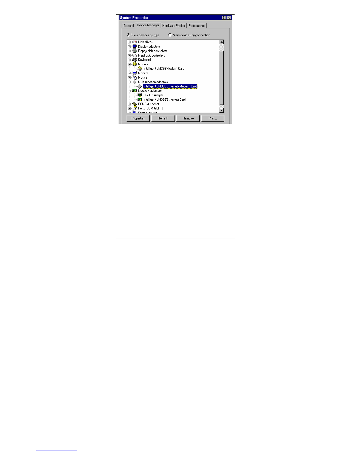
1. Remove the Multi-function adapters properties
from the Device Manager folder of System in
Control Panel program group.
Supposedly the Intelligent xxxxx (Mo
dem)
Card in Modem properties and the Intelligent
xxxxx (10/100 Fast Ethernet) Card in Network
adapters
properties will be removed automatically. If not,
remove them manually.
Page 45
- 39 -
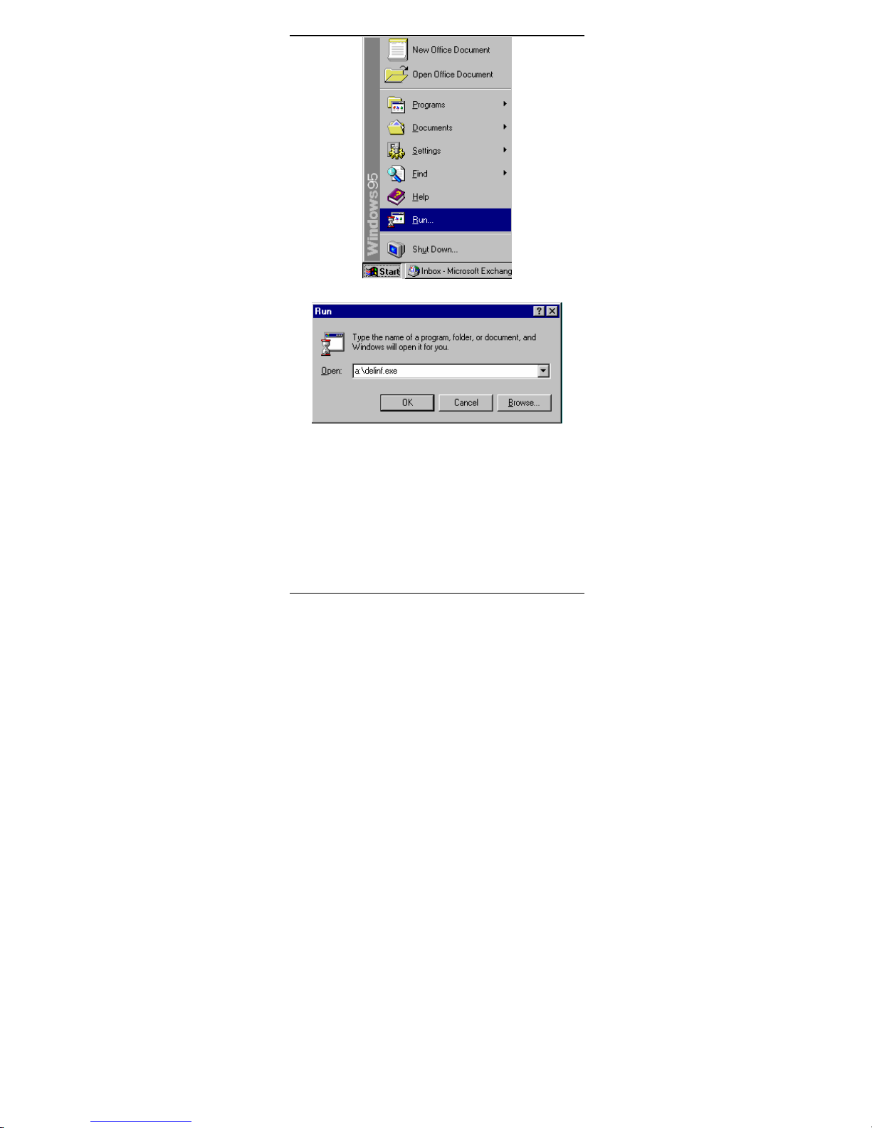
2. Click Start button in Windows 95/98 main
screen
then select Run….
3. Insert the Driver Disk, then enter A:\delinf.exe
then click on OK.
4. Re-start Windows 95/98. Now your DirectPort
PC Card is completely uninstalled.
Page 46
- 40 -
Page 47
- 41 -
8. APPENDIX C: AT COMMAND
QUICK REFERENCE
8.1 Modem AT Commands
Basic AT Command Set
Command Options Function & Description
A/ Re-execute the last command
string
<any
key>
Terminate the current
connection attempt when
entered in handshaking state
All the following commands require an “AT”
prefix
A Go off-hook and attempt to
establish a connection
without waiting for a ring
Bn Line modulation options
B0 Select V.22 mode for 1200
bps connection
B1 * Select Bell 212A for 1200
Page 48
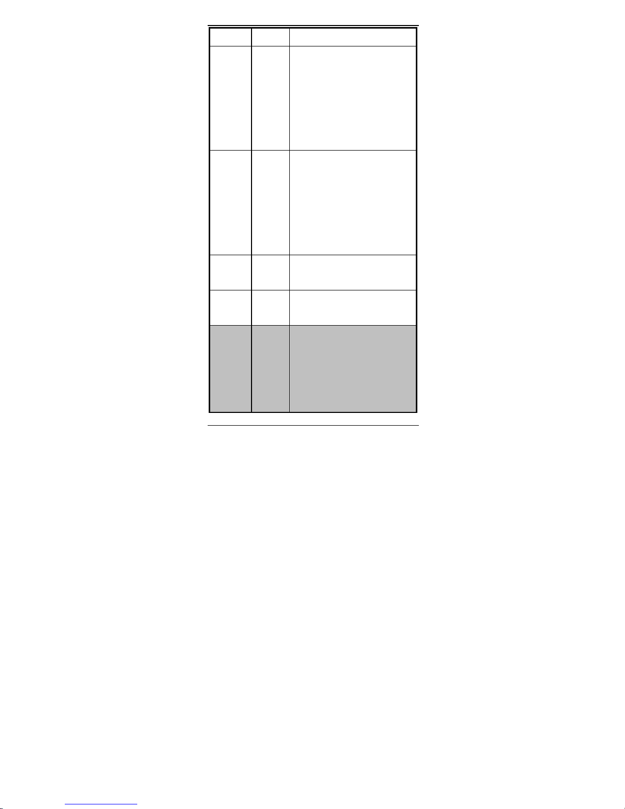
- 42 -
bps connection
B2 Select V.23 1200 bps for
receiving, 75 bps for
transmitting in originate
mode; 75 bps
for receiving and 1200 bps for
transmitting in answer mode
B3 Select V.23 75 bps for
receiving, 1200 bps for
transmitting in originate
mode; 1200 bps for receiving
and 75 bps for transmitting in
answer mode
B15 Select V.21 for 300 bps
connection
B16 Select Bell 103 for 300 bps
connection
Dn Dial command, beginning the
dialing sequence. The string
“n” (telephone number and
modifiers) listed as follows
is entered after the “D”
Page 49

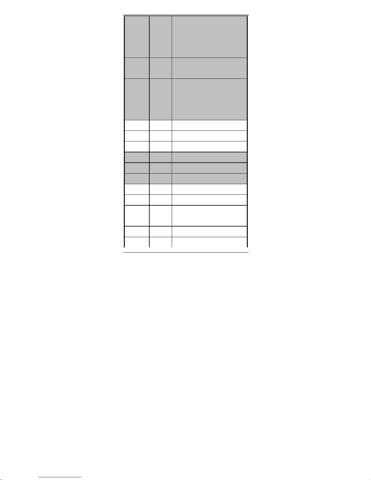
- 43 -
command
L Re-dial last number. Should
be the first character
following ATD, ignored
otherwise
P Pulse dial.
R Reverse dial. Originate call
in answer mode (go on-line
in answer mode)
S=n Dial the phone number stored
in NVRAM at location “n”
(n=0, 1, 2, 3)
T DTMF tone dial.
W Wait for second dial tone.
The modem waits for the
second dial tone before
processing the dial string
, Pause. Cause the modem to
pause for a time before
processing the next character
in the dial string (specified
by S8 register)
Page 50
- 44 -
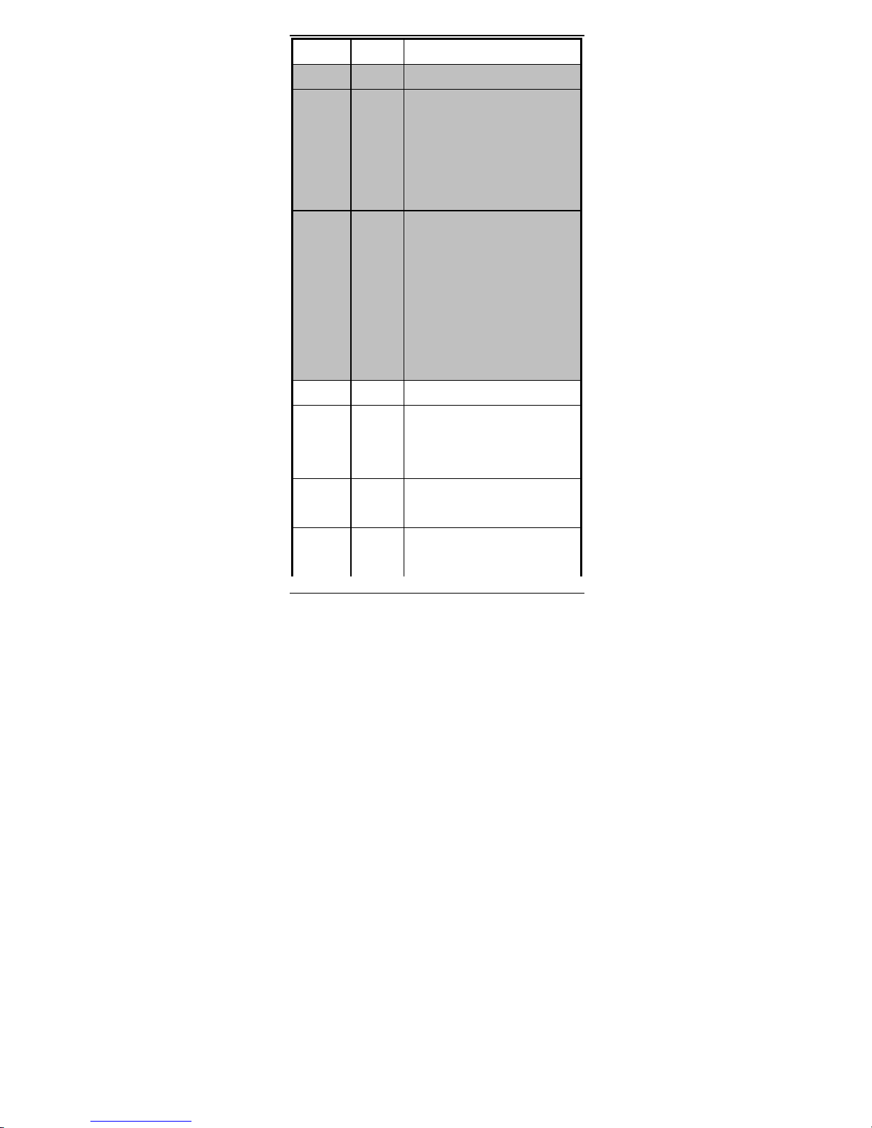
! Hook Flash (for call
transfer). Cause the modem
to go on-hook for 0.5 second
then return to off-hook
@ Wait for 5 seconds of
silence after dialing number
; Return to command state
after dialing a number
without disconnecting the
call
En AT command echo options
E0 Echo disabled
E1 * Echo enabled
Hn Switch-hook control
H0 * Modem goes on-hook
H1 Modem goes off-hook
Mn Speaker control
M0 Speaker always off
M1 * Speaker on until carrier
present
M2 Speaker always on
M3 Speaker off during dialing
Page 51
- 45 -
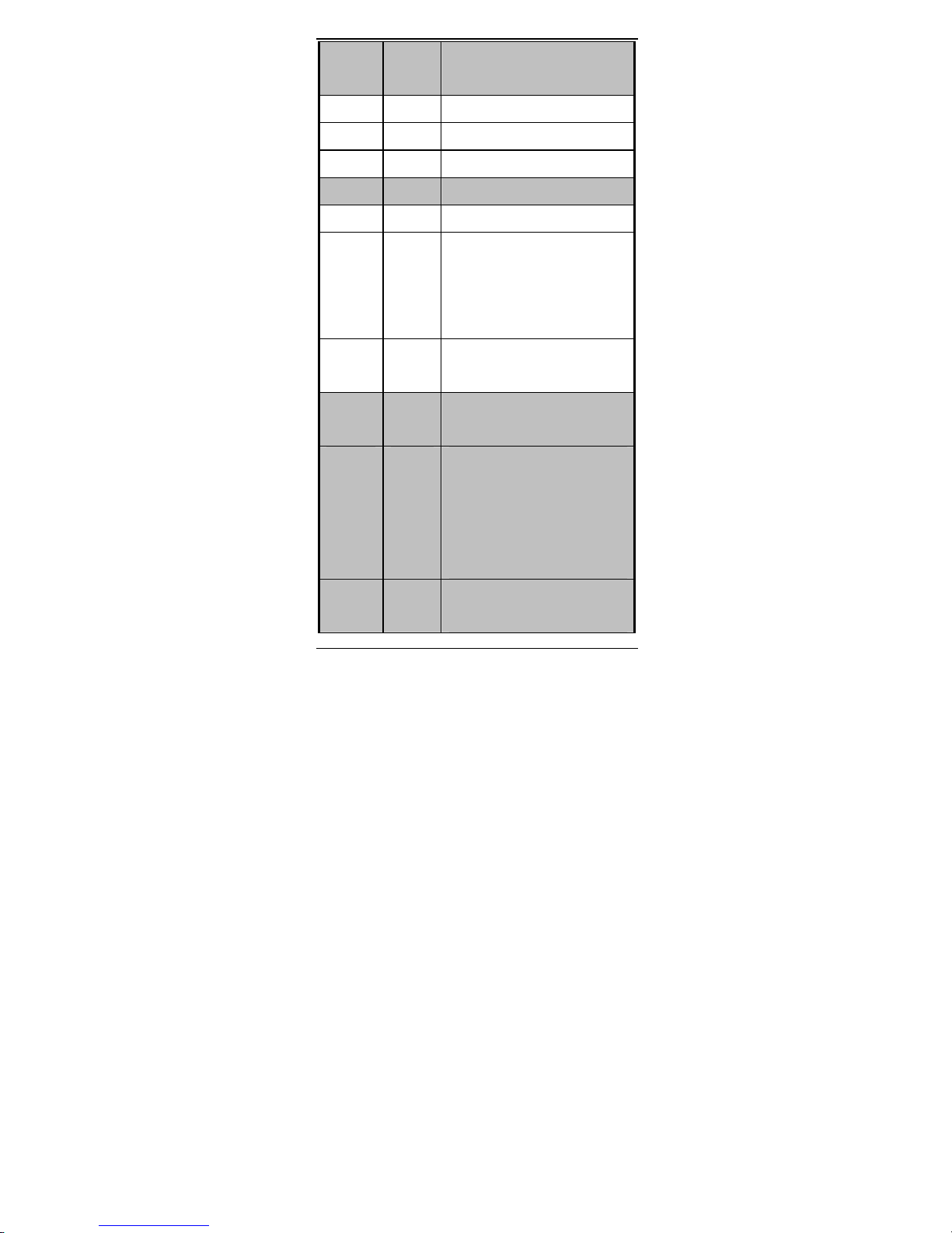
and on until carrier present
Nn Select negotiate handshake
N0 When originating or
answering, handshake only at
the communication rate
specified by S37 register
and “ATBn” and no fallback
N1 *
When originating or answering,
start handshaking only at the
communication standard
specified by S37 register and
“ATBn” During handshake,
fallback to a lower speed may
occur.
On Go on-line
O0 Return modem to a previously
established state (return to
data mode).
O1
Begin a retrain sequence, then
return to on-line state.
O3 Issue a rate re-negotiation,
then return to on-line state.
Page 52
- 46 -
P
Enable pulse dialing (Disabled
in CTR 21 approved models)
Qn Result code display options
Q0 * Result code enabled
Q1 Result code disabled
T Enable tone dialing
Vn Result code form
V0
Display result code in numeric
form (see
also the result code options
table)
V1 *
Display result code in verbose
(text) form
Wn Select extended result code
options
W0*
CONNECT result code reports DTE
speed. Disable protocol result
codes.
(see also the “Result Code
Options Table”)
W1
CONNECT result code reports DTE
speed. Enable protocol result
Page 53

- 47 -
codes.
W2
CONNECT result code reports DCE
speed. Enable protocol result
codes.
Xn Select result codes/call
progress options
X0
Display CONNECT or “1” for all
speeds.
Ignore dial tone and busy tone
detection.
X1
Display connect message and the
modem’s data rate, and an
indication of the modem’s err
or
correction and data
compression.
Ignore dial tone and busy tone
detection.
X2
Display connect message and the
modem’s data rate, and an
indication of the modem’s error
correction and data
compression.
Page 54

- 48 -
Check dial tone before
proceeding dialing,
ignore busy tone detection.
X3
Display connect message and the
modem’s data rate, and an
indication of the modem’s error
correction and data
compression.
Ignore dial tone before
proceeding dialing,
check busy tone after making
dialing.
X4 * Display connect
message and the
modem’s data rate, and an
indication of the modem’s error
correction and data
compression.
Check dial tone and busy tone.
X5 Same as X4.
X6 Same as X4.
X7
Display CONNECT or “1” for all
speeds.
Page 55
- 49 -
Check dial tone and busy tone.
Zn Recall stored profile
Z0 Reset and recall user profile
0. Either Z0 or
Z1 restores the same single
profile.
* Manufacturer default
Extended “AT&” (Ampersand) Command Set
Command Options Function & Description
&Cn Data carrier detect option
&C0 State of carrier from remote
modem is ignored. DCD circuit
is always on
&C1 * DCD turns on when the remote
modem’s carrier signal is
detected, and off when the
carrier signal is not
detected.
&Dn Data Terminal Ready (DTR)
option.
&D0 DTR ignored
Page 56
- 50 -
&D1 Go to command mode on on-to-
off DTR transition
&D2 * Hang up and go to command
mode on on-to-off DTR
transition. Auto-answer is
disabled if DTR is low
&D3 Hang up and reset from user
profile 0 on the on-to-off
DTR transition
&F Recall factory default
setting as active
configuration
&Gn V.22bis guard tone option
&G0 * No guard tone
&G1 550 Hz guard tone
&G2 1800 Hz guard tone
&Kn Set local flow control
&K0 Disable flow control
&K3 * Enable bi-directional
hardware flow control
(CTS/RTS)
&K4 Enable bi-directional
Page 57
- 51 -
software flow control
(XON/XOFF)
&Pn Pulse dialing make/break
ratio selection
&P0 Make=39%, Break=61%,
international version
(Default)
Make=33%, Break=67% for use
in 20 pps, Japanese version
&P1 Make=33%, Break=67%,
international version
Make=33%, Break=67% for use
in 10 pps, Japanese version
(Default)
&Qn Async communications mode
options
&Q0 Async mode, buffered (same as
“AT\N0”)
&Q5 * Error control mode, buffered
(same as “AT\N3”)
&Q8 MNP error control mode. If an
MNP error control protocol is
Page 58
- 52 -
not established, the modem
will fallback according to
the current setting in S36
register.
&Q9 V.42 or MNP error control
mode. If neither error
control protocol is
established, the modem will
fallback according to the
current setting in S36
register.
&Sn Data Set Ready (DSR) option
&S0 * DSR always on
&S1 DSR on during handshake and
on-line, off in test mode or
idle mode
&Tn Self-test commands
&T0 Terminate any test in
progress
&T1 Local analog loopback test
&T3 Local digital loopback (LDL)
test
Page 59
- 53 -
&T6 Remote digital loopback test,
in normal mode
&V View active file and stored
phone numbers
&W Store active configuration
into the modem’s NVRAM
&Zn=x Store telephone number
n=0 to 3
x=<string> see also the
dial modifier
in ”ATDn” command
The max. number of digits per
string is 40.
* Manufacturer default
Extended “AT\” (Back Slash) Command Set
Command Options Function & Description
\Jn Constant DTE speed option
\J0 * DCE and DTE rates are
Page 60

- 54 -
independent
\J1 Force the DTE interface
speed to the DCE connection
rate (line speed) after on-
line
\Nn Error control mode options
\N0 Buffered mode, no error
control (flow control is
allowed).
\N1 Direct mode, no error
control (no flow control is
allowed).
\N2 MNP reliable mode. If MNP 2-
4 error control
establishment fails, the
modem disconnects.
\N3 * V.42, MNP or buffer mode.
The modem attempts to
connect in V.42 mode. If
this fails, the modem
attempts to connect in MNP
mode. If this fails, the
Page 61
- 55 -
modem connects in buffer
mode.
\N4 V.42 or disconnect. The
modem attempts to connect in
V.42 mode. If this fails,
the call will be
disconnected.
\Qn Local flow control options
\Q0 Disable flow control (same
as “AT&K0”)
\Q1 XON/XOFF software flow
control (same as “AT&K4”)
\Q3 * RTS/CTS hardware flow
control (same as “AT&K3”)
\Tn Set inactive timer (for
buffer mode only)
n=0 * Disable inactive timer
n=1 -
255
Enable inactive timer.
Length in minutes
\Vn Protocol result codes
\V0 Disable protocol result code
appended to DCE speed
Page 62
- 56 -
\V1 * Enable protocol result code
appended to DCE speed
* Manufacturer default
Extended “AT%” (Percent) Command Set
Command Options Function & Description
%B View numbers in blacklist. If
blacklisting is in effect,
this command displays the
numbers for which the last
call attempted in the past
two hours failed. The ERROR
result code appears in the
countries that do not require
blacklisting.
%Cn Data compression control
%C0 No data compression
Page 63
- 57 -
%C1 * V.42bis/MNP 5 data
compression enabled.
* Manufacturer default
Extended “AT-” (Dash) Command Set
Command Options Function & Description
-Cn Data calling tone options
-C0 * Disable data calling tone
-C1 Enable data calling tone
(the freq. is 1,300 Hz with
a cadance of 0.5 sec. ON and
2 sec. OFF)
* Manufacturer default
8.2 Result Code Options
Result Code Options Table
ATV0 ATV1 X0 X1 X2 X3 X4 X7
0 OK
✓ ✓ ✓ ✓ ✓ ✓
1 CONNECT
✓ ✓ ✓ ✓ ✓ ✓
2 RING
✓ ✓ ✓ ✓ ✓ ✓
3 NO CARRIER
✓ ✓ ✓ ✓ ✓ ✓
4 ERROR
✓ ✓ ✓ ✓ ✓ ✓
5 CONNECT 1200 EC* @ @ @ @
6 NO DIAL TONE
✓
✓ ✓
7 BUSY
✓ ✓ ✓
8 NO ANSWER
✓ ✓ ✓ ✓ ✓ ✓
Page 64
- 58 -
10 CONNECT 2400 EC * @ @ @ @
11 CONNECT 4800 EC * @ @ @ @
12 CONNECT 9600 EC * @ @ @ @
13 CONNECT 14400 EC * # # # #
14 CONNECT 19200 EC * @ @ @ @
18 CONNECT 57600 EC * % % % %
24 CONNECT 7200 EC * # # # #
25 CONNECT 12000 EC * # # # #
28 CONNECT 38400 EC * % % % %
40 CONNECT 300 EC * @ @ @ @
55 CONNECT 21600 EC * # # # #
56 CONNECT 24000 EC * # # # #
57 CONNECT 26400 EC * # # # #
58 CONNECT 28800 EC * # # # #
59 CONNECT 31200 EC * # # # #
60 CONNECT 33600 EC * # # # #
70 CONNECT 32000 EC * # # # #
71 CONNECT 34000 EC * # # # #
72 CONNECT 36000 EC * # # # #
73 CONNECT 38000 EC * # # # #
74 CONNECT 40000 EC * # # # #
75 CONNECT 42000 EC * # # # #
76 CONNECT 44000 EC * # # # #
77 CONNECT 46000 EC * # # # #
78 CONNECT 48000 EC * # # # #
79 CONNECT 50000 EC * # # # #
80 CONNECT 52000 EC * # # # #
81 CONNECT 54000 EC * # # # #
82 CONNECT 56000 EC * # # # #
86 CONNECT 16800 EC # # # #
Page 65
- 59 -
*
87 CONNECT 115200 EC * % % % %
88 DELAYED **
89 BLACKLISTED **
90 BLACKLIS FULL **
100 CONNECT 28000 # # # #
101 CONNECT 29333 # # # #
102 CONNECT 30666 # # # #
103 CONNECT 33333 # # # #
104 CONNECT 34666 # # # #
105 CONNECT 37333 # # # #
106 CONNECT 38666 # # # #
107 CONNECT 41333 # # # #
108 CONNECT 42666 # # # #
109 CONNECT 45333 # # # #
110 CONNECT 46666 # # # #
111 CONNECT 49333 # # # #
112 CONNECT 50666 # # # #
113 CONNECT 53333 # # # #
114
CONNECT 54666 # # # #
@ DTE/DCE speed
# DCE speed (line speed)
% DTE speed
* EC only appears when the Extended Result Code
options are enabled
** For Blacklisting function enabled countries
only
Extended Result Code Options Table
ATV0 ATV1 W0 W1 W2 W2\V0
5 CONNECT 1200
✓
✓
5 CONNECT 1200 EC*
✓ ✓
10 CONNECT 2400
✓
✓
10 CONNECT 2400 EC *
✓ ✓
11 CONNECT 4800
✓
✓
11 CONNECT 4800 EC *
✓ ✓
12 CONNECT 9600
✓
✓
12 CONNECT 9600 EC *
✓ ✓
13 CONNECT 14400
✓
13 CONNECT 14400 EC *
✓
14 CONNECT 19200
✓
✓
14 CONNECT 19200 EC *
✓ ✓
Page 66
- 60 -
18 CONNECT 57600
✓
18 CONNECT 57600 EC *
✓
24 CONNECT 7200
✓
24 CONNECT 7200 EC *
✓
25 CONNECT 12000
✓
25 CONNECT 12000 EC *
✓
28 CONNECT 38400
✓
✓
28 CONNECT 38400 EC *
✓ ✓
40 CONNECT 300
✓
✓
40 CONNECT 300 EC *
✓ ✓
55 CONNECT 21600
✓
55 CONNECT 21600 EC *
✓
56 CONNECT 24000
✓
56 CONNECT 24000 EC *
✓
57 CONNECT 26400
✓
57 CONNECT 26400 EC *
✓
58 CONNECT 28800
✓
58 CONNECT 28800 EC *
✓
59 CONNECT 31200
✓
59 CONNECT 31200 EC*
✓
60 CONNECT 33600
✓
60 CONNECT 33600 EC *
✓
70 CONNECT 32000
✓
70 CONNECT 32000 EC*
✓
71 CONNECT 34000
✓
71 CONNECT 34000 EC*
✓
72 CONNECT 36000
✓
72 CONNECT 36000 EC*
✓
73 CONNECT 38000
✓
73 CONNECT 38000 EC*
✓
74 CONNECT 40000
✓
74 CONNECT 40000 EC*
✓
75 CONNECT 42000
✓
75 CONNECT 42000 EC*
✓
76 CONNECT 44000
✓
76 CONNECT 44000 EC*
✓
77 CONNECT 46000
✓
77 CONNECT 46000 EC*
✓
Page 67

- 61 -
78 CONNECT 48000
✓
78 CONNECT 48000 EC*
✓
79 CONNECT 50000
✓
79 CONNECT 50000 EC*
✓
80 CONNECT 52000
✓
80 CONNECT 52000 EC*
✓
81 CONNECT 54000
✓
81 CONNECT 54000 EC*
✓
82 CONNECT 56000
✓
82 CONNECT 56000 EC*
✓
86 CONNECT 16800
✓
86 CONNECT 16800 EC *
✓
87 CONNECT 115200
✓
87 CONNECT 115200 EC *
✓
* EC is replaced by one of the following symbols.
V.42bis V.42 error control and V.42bis data
compression
V.42 V.42 error control only
MNP5 MNP 4 error control and MNP 5 data
compression
MNP4 MNP 4 error control only
NoEC No error control and data control
protocols
Page 68
- 62 -
9. APPENDIX D: SREGISTERS QUICK
REFERENCE
S-Registers, TSn=x”
Register Dec. Function & Description Default
S0= 0 -
255
Set the num
ber of the rings
required before the modem
automatically answers
a call. Set 0=0” to
disable auto-answer mode
000
S1= 0 -
255
Count the incoming rings
and store the value to this
register. The value of this
register is incremented
with each ring. If no
rings
occur over an 8 sec.
interval, this register is
cleared. User can read but
should not change this
value
000
S2= 0 - S2 holds the decimal value 043
Page 69

- 63 -
255
of the ASCII character used
as the escape character.
The default value (043)
corresponds to
an ASCII character “+”. A
value of 128
to 255 disables the escape
process, i.e.,
no escape character will be
recognized
S3= 0 -
127
Hold the decimal value of
the Carriage Return <CR>
character used as the
command line and result code
terminator. Pertain to
asynchronous operation only
013
S4= 0 -
127
Hold the decimal value of
the character recognized
as a line feed. The line
feed control character is
output after the carriage
return control character
010
Page 70

- 64 -
if verbose result code are
used.
S5= 0 -
32,
127
Hold the decimal value of
the character recognized
as a backspace. The modem
will not recognize the
backspace character if
this register is set to a
value greater than 32
008
S6= Set the length of time, in
seconds, that the modem
must wait (minimum 2
seconds even if the value
is less than 2) after
going off-hook before
dialing the first digit of
the telephone number
2 -
65
For international version 002
4 -
65
For Japanese version 004
S7= Set the time, in seconds,
Page 71

- 65 -
that the modem must wait
before hanging up because
carrier is not detected
1 -
255
For international version 050
35 -
59
For Japanese version 050
S8= 0 -
65
Set the time, in seconds,
that the modem must pause
when the “,” dial modifier
is encountered in the dial
string
002
S10= 1 -
255
Set the length of time, in
tenths of a second, that
the modem waits before
hanging up after a loss of
carrier
020
S11= 50 -
150
DTMF duration and inter
digit delay. Set the
duration and spacing, in
mini-seconds, in DTMF
touch tine dialing
095
Page 72
- 66 -
S12= 0 -
255
Define the maximum period,
in 2-hundredths of a
second, allowed between
consecutive asynchronous
escape character “+”
(plus) for the escape
sequence to be considered
valid
050
S28= 0 -
255
V.34 modulation en-
/disabler
0: disabled
1- 255: enabled
001
S30= 0 -
90
Inactivity timer. Set the
length of time, in minutes,
that the modem counts when
there is no data flow in or
out the DTE serial port. A
connection is disengaged
when the counter reaches the
preset value. Set S30 =0 to
disable the inactivity
timer.
For buffer mode only.
000
Page 73
- 67 -
S36= Negotiation fallback
options
007
0, 2 Hang up
1, 3 Fall back to an async
connection
4, 6 Attempt MNP mode. If MNP
fails, hang up.
5, 7 Attempt MNP mode. If MNP
fails, fallback to async
connection.
S37= Desired DCE speed (line
speed)
000
0 Maximum modem speed
2 Attempt 1200/75 bps
connection
3 Attempt to a 300 bps
connection
5 Attempt to a 1200 bps
connection
6 Attempt to a 2400 bps
connection
7 Attempt to a 4800 bps
Page 74
- 68 -
connection
8 Attempt to a 7200 bps
connection
9 Attempt to a 9600 bps
connection
10 Attempt to a 12000 bps
connection
11 Attempt to a 14400 bps
connection
12 Attempt to a 16800 bps
connection
13 Attempt to a 19200 bps
connection
14 Attempt to a 21600 bps
connection
15 Attempt to a 24000 bps
connection
16 Attempt to a 26400 bps
connection
17 Attempt to a 28800 bps
connection
18 Attempt to a 31200 bps
Page 75
- 69 -
connection
19 Attempt to a 33600 bps
connection
S38= 56K Dial Line Rate
Options. Set the max. 56K
downstream speed that the
modem attempts to connect
(Selection for K56flex
mode)
001
0 56K disabled
1 56K enabled, auto-speed
selection, max. modem
speed
2 32000 bps
3 34000 bps
4 36000 bps
5 38000 bps
6 40000 bps
7 42000 bps
8 44000 bps
9 46000 bps
10 48000 bps
Page 76

- 70 -
11 50000 bps
12 52000 bps
13 54000 bps
14 56000 bps
S38= 56K Dial Line Rate
Options. Set the max. 56K
downstream speed that the
modem attempts to
connect.(Selection for
V.90 mode)
001
0 V.90 Disabled
1 V.90 auto-speed selection
max. modem speed
2 28800 bps
3 29333 bps
4 30666 bps
5 32000 bps
6 33333 bps
7 34666 bps
8 36000 bps
9 37333 bps
10 38666 bps
Page 77
- 71 -
11 40000 bps
12 41333 bps
13 42666 bps
14 44000 bps
15 45333 bps
16 46666 bps
17 48000 bps
18 49333 bps
19 50666 bps
20 52000 bps
21 53333 bps
22 54666 bps
23 56000 bps
S48= 7,
128
LAPM error control and
feature negotiation.
S48=7 Negotiation
enabled
S48=128 Negotiation
disabled. Force
immediate
fallback options
Page 78
- 72 -
specified in S36
S36=0 or 2, and S48=7
LAPM or hang up
S36=0 or 2 and S48= 128
Don use
S36=1 or 3, and S48=7
LAPM or async
S36=1 or 3, and S48=128
Async
S36=4 or 6, and S48=7
LAPM, MNP or hang up
S36=4 or 6, and S48=128
MNP or hang up
S36=5 or 7, and S48=7
LAPM, MNP or async
S36=5 or 7, and S48=128
MNP or hang up
S89= 0,
5 -
60
Sleep mode control timer.
Specify the number of
seconds of inactivity (no
character sent from DTE,
030
Page 79
- 73 -
no RING) in the off-line
command state before the
modem places itself into
standby mode. A value of
“0” prevents standby mode.
If a number between 1 and
4 is entered for this
register, it will set the
value to 5
S91= 6 -
15
Transmitting power level
adjustment (Japanese
version only)
Range: -6 dBm to -15 dBm
Default: -15 dBm
014
 Loading...