

Page 1

DMC-920
10/100BASE-TX to
100BASE-FX
Single-Fiber
Dual-Wavelength
Media Converter Kit
User’s Guide
Rev. 02 (DEC. 2004)
Printed In Taiwan
RECYCLABLE
Page 2

2
TABLE OF CONTENTS
TABLE OF CONTENTS.......... 2
INTRODUCTION................. 2
DUAL-WAVELENGTH SINGLE-FIBER ............3
PRODUCT FEATURES ...... 3
INSTALLATION.................. 4
SELECTING A SITE FOR THE EQUIPMENT.....4
CONNECTING TO POWER.............................4
SLIDING SWITCH ..........................................4
INSTALLING IN A CHASSIS ............................5
LED INDICATOR ...........................................6
LINK PASS THROUGH FUNCTION .................8
DUAL WAVELENGTH SINGLE FIBER...........10
SPECIFICATIONS............12
INTRODUCTION
Thank you for choosing the 10/100BASE Fast Ethernet
Media Converter, the Dual Wavelength Single Fiber
Page 3

3
Converter introduced here provides a pair of one channel
single fiber media conversion between 10/100BASE-TX and
100BASE-FX Single Fiber.
Dual-Wavelength Single-Fiber
These types of Single-Fiber modules combine transmit and
receive signals onto one fiber strand using two wavelengths.
This design avoids the budget losses incurred by the
single-wavelength single-fiber technology, and minimizes
any possibility of reflections in the system. The units on both
ends of a link are different. One module uses one wavelength
to transmit and a second wavelength to receive, while the
other module flips that relationship. For this reason these
units are sold in pairs.
PRODUCT FEATURES
y A pair of One-channel single fiber media conversion
between 10/100BASE-TX and 100BASE-FX.
y Two different type of transmitting wavelength: One
wavelength with bi-directional for both transmit and
receive.
− DMC-920R: TX: 1310µm; RX: 1550µm.
− DMC-920T: TX: 1550µm; RX: 1310µm
y Auto negotiation of speed and duplex mode on TX port
y Auto MDI-X on TX port
y One slide switch for configuring fixed half/full duplex
modes
y Store-and-forward mechanism
y Back-pressure & IEEE802.3x compliant flow control
y Full wire-speed forwarding rate
y Front panel status LEDs
y Used as a stand-alone device or with a chassis
y Hot-swappable when used with a chassis
y Manageable through Intelligent Chassis System
Page 4

4
INSTALLATION
This chapter gives step-by-step installation instructions for
the Converter.
Selecting a Site for the Equipment
As with any electric device, you should place the equipment
where it will not be subjected to extreme temperatures,
humidity, or electromagnetic interference. Specifically, the
site you select should meet the following requirements:
1. The ambient temperature should be between 32 and
104 degrees Fahrenheit (0 to 40 degrees Celsius).
2. The relative humidity should be less than 90 percent,
non-condensing.
3. Surrounding electrical devices should not exceed the
electromagnetic field (RFC) standards for IEC 801-3,
Level 2 (3V/M) field strength.
4. Make sure that the equipment receives adequate
ventilation. Do not block the ventilation holes on each
side of the switch or the fan exhaust port on the side or
rear of the equipment.
5. The power outlet should be within 1.8 meters of the
switch.
Connecting to Power
1. This Converter is a plug-and-play device.
2. Connect the supplied AC to DC power adaptor with a
power voltage of 7.5Vdc/1.5Amp to the DC-Jack on
the converter, and then attach the plug into a standard
AC outlet.
Sliding Switch
There is a sliding switch for duplex mode setting for fiber
Page 5
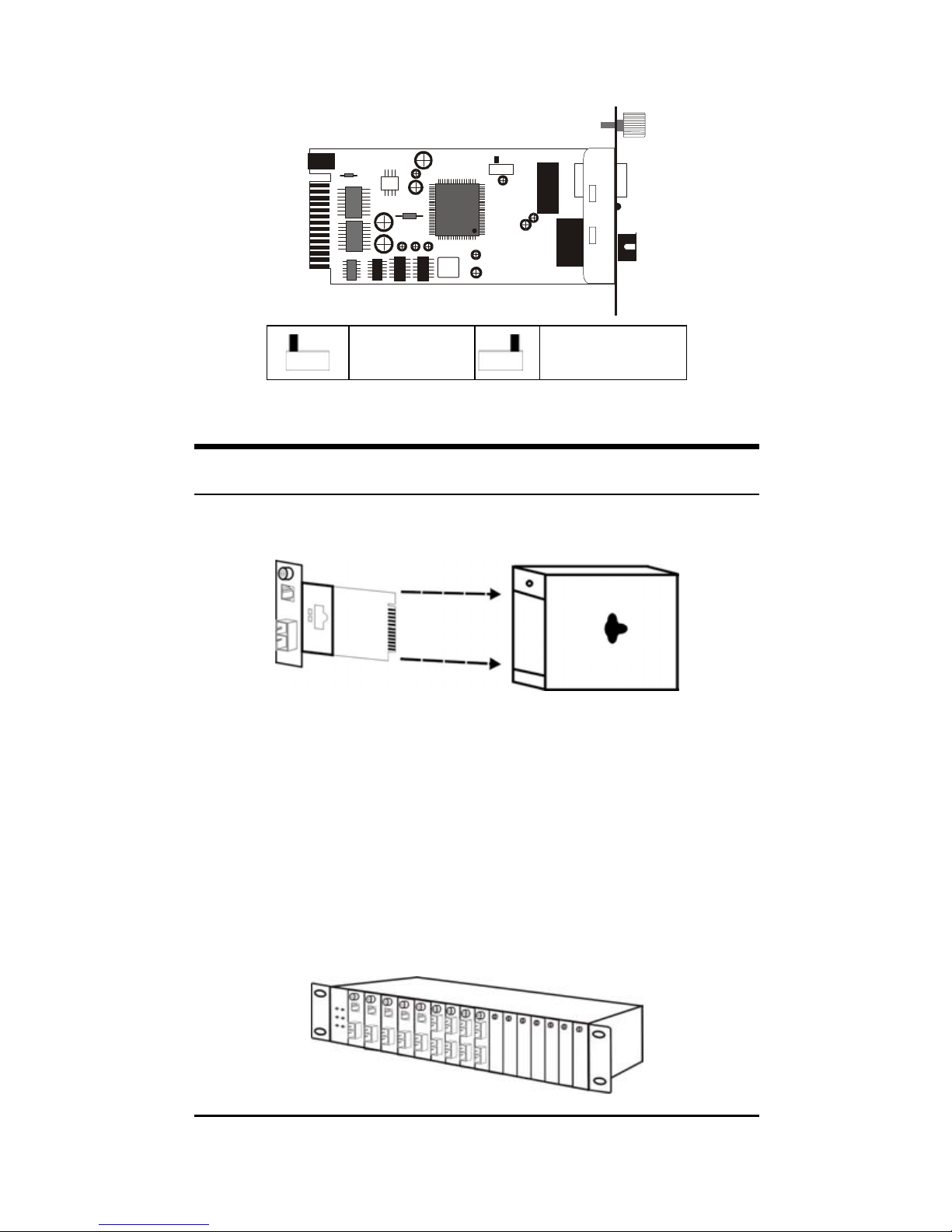
port. Refer to the table below for more details.
SW1
Half Duplex
Full Duplex
(default)
Installing in a Chassis
The Converter can be fit into any of the expansion slots
on a special designed chassis.
y First, install the converter onto a carrier supplied with
the chassis:
Step 1- Unscrew and pull out the media converter
board.
Step 2- Plug in the media board to any of the vacant
slot.
Step 3- Fit the converter onto the carrier and use the
screw to secure it.
5
Page 6
LED Indicator
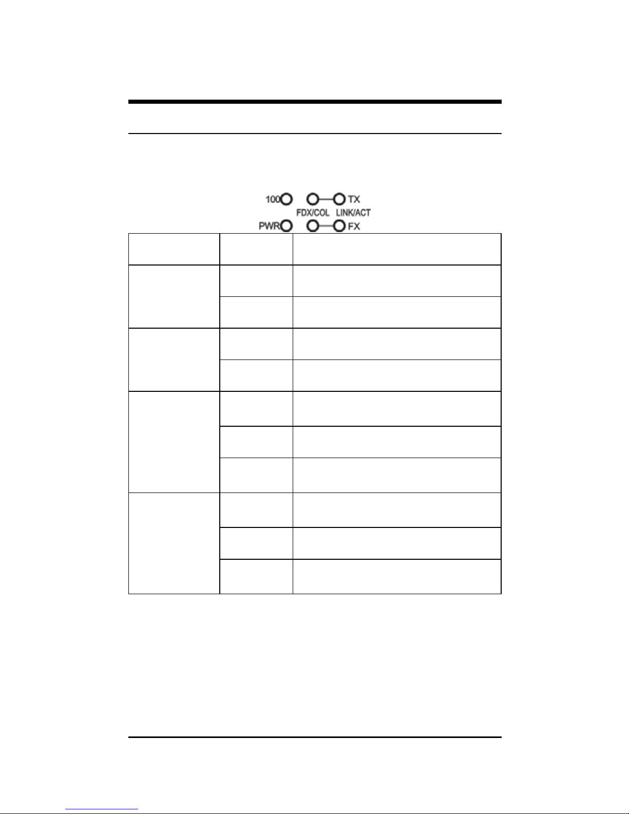
The LED indicators give you instant feedback on status of the
converter:
LEDs State Indication
Steady Power on
Power
(PWR)
Off Power off
Steady Runs at 100Mbps on TX port
100 Mbps
(100)
Off Runs at 10Mbps on TX port
Steady
(FDX)
Connection in full duplex mode
FDX stands for FULL-DUPLEX
Lights off Connection in half duplex mode
TX Port (TX)
FX Port (FX)
FDX/COL
Blinking
(COL)
Data collision
Steady
(LINK)
A valid network connection
established
Lights off Not Linking
TX Port (TX)
FX Port (FX)
LINK/ACT
Blinking
(ACT)
Transmitting or receiving data
ACT stands for Activity
The optional Management Chassis that can control this Smart
Media Converter through the management system, this Smart
Media Converter can be controlled through Web Browser,
SNMP management utility and terminal emulation program.
6
Page 7
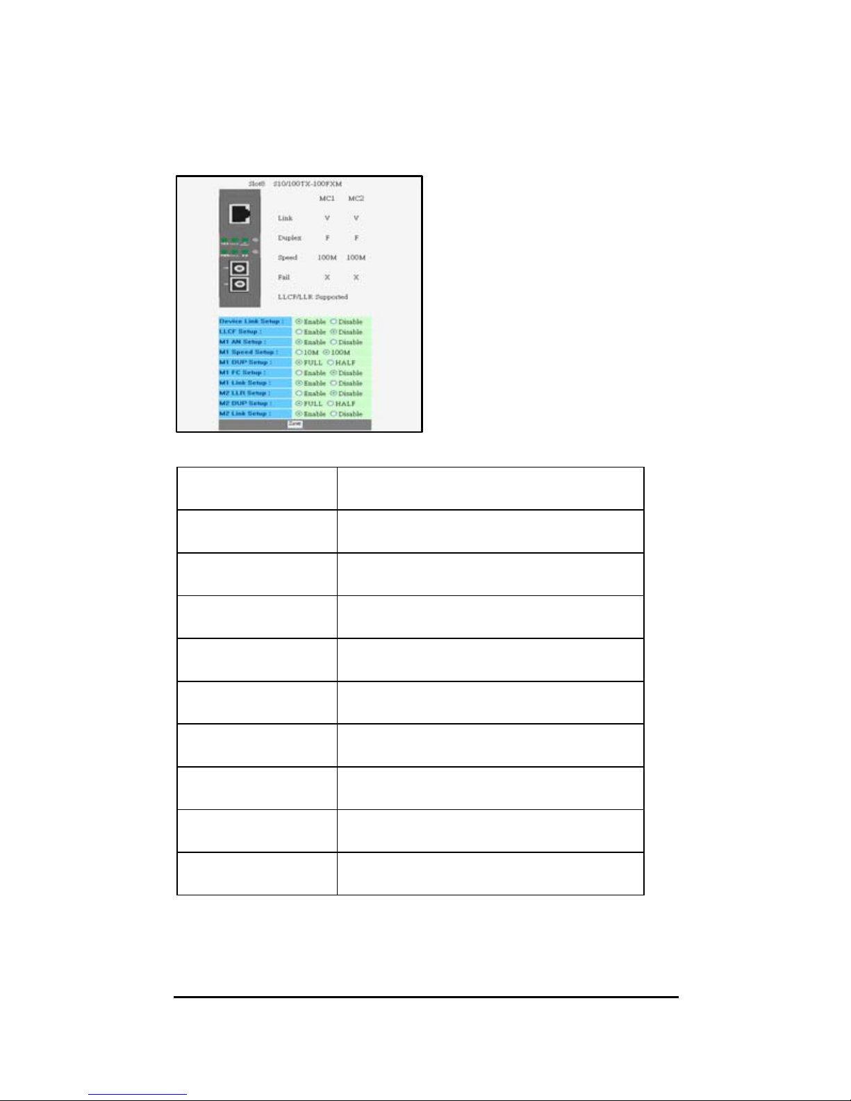
The Management Chassis will detect the default reset on the
DIP switches and display out the status, also the Management
Chassis can control the function through the management
system.
Through the optional Media
Converter Chassis System
via Management Module,
you can control the setting of
this Smart Media Converter.
To set the Fiber and UTP
(FDX/HDX), UTP (Auto
negotiation/Manual), Speed
(10M/100M), LLR
(Enable/Disable), LLCF
(Enable/Disable)
Device Link Setup
To enable or disable the connection of
both UTP port and Fiber port
LLCF Setup
To enable or disable the LLCF function
of the device
M1 AN Setup
To set the UTP to Auto-negotiation or
Forced Mode
M1 Speed Setup To set the speed of UTP to 10M or 100M
M1 DUP Setup
To set the Duplex Mode of UTP port to
Full or Half
M1 FC Setup
To set the Flow Control of the UTP to
enable or disable
M1 Link Setup
To enable or disable the connection of the
UTP port
M2 LLR Setup
To enable or disable the LLR function of
the Fiber port
M2 DUP Setup
To set the Duplex Mode of Fiber port to
Full or Half
M2 Link Setup
To enable or disable the connection of the
Fiber port
7
Page 8
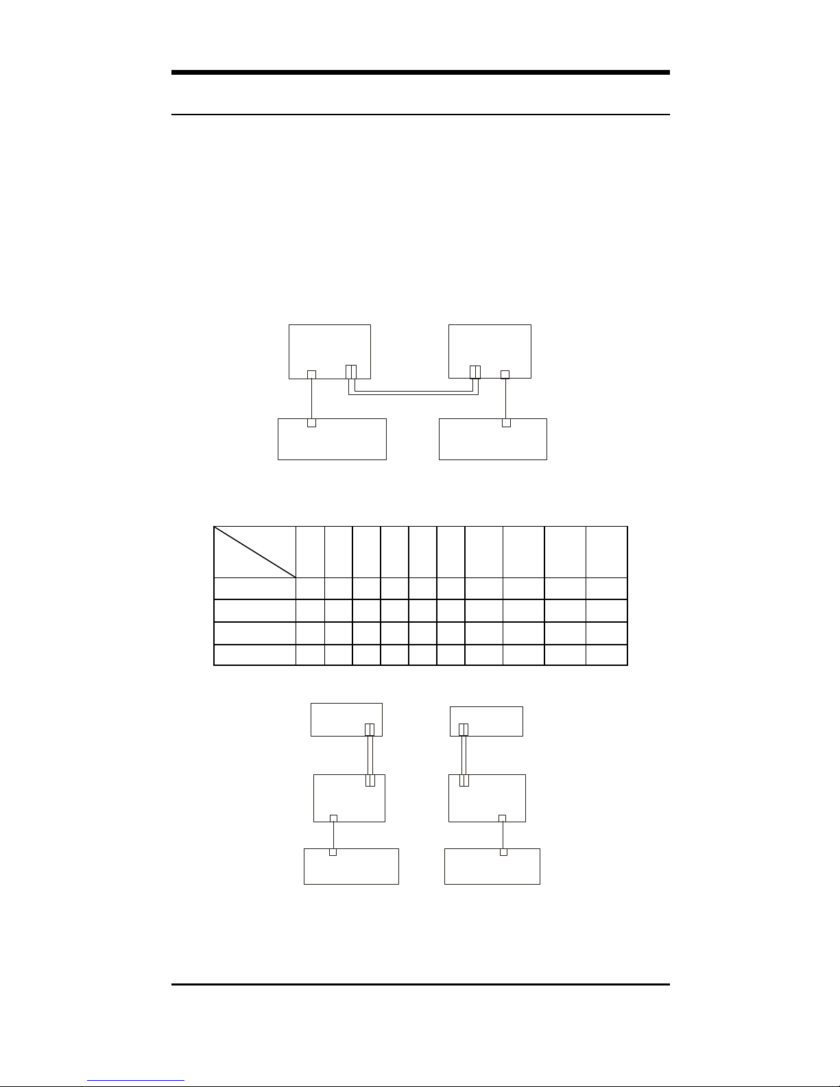
Link Pass Through Function
LLR (Link Loss Return)
When a device connected to the converter and the fiber line
loss the link, the converter’s fiber will disconnect the link of
transmit.
The switch 5 is to enable or disable the LLR function of the
media converter.
TX RX
Switc h B
Switc h A
Cable 3
Cable 2
Cable 4
Cable 1
Media
Converter B
Med ia
Converter A
TX RX
LLCF Off
LLR Off
LLCF Off
LLR On
LINK 6
Copper
LINK 5
Copper
Copper
LINK 4
LINK FAIL 4
Fiber
LINK 3
LINK FAIL 3
Fiber
LINK 1
LINK FAIL 1
Copper
LINK 2
LINK FAIL 2
The table below shows the status happens when LLR function
is working through two ways of connection
Link
Status
Disconnect
Link 1 Link 2 Link 3 Link 4 Link 5 Link
6
Link
Fail 1
LED
Link
Fail 2
LED
Link
Fail 3
LED
Link
Fail 4
LED
Cable 1 On On Off On On On Off Off On Off
Cable 2 Off On Off On On On On Off On Off
Cable 3 On On On Off On Off Off Off Off On
Cable 4 On Off On On Off On Off On Off Off
Fib e r
Copper
TXRX
Fiber
Copper
Swit c h C
Swit c h D
LINK 8
LINK 3
LINK 1
LINK 7
Cable 3
Cable 2
Cable 4
Cable 1
Media
Converter B
Media
Converter A
LINK 2
LINK 4
LINK FAIL 4
LINK FAIL 3
LINK FAIL 1
LINK FAIL 2
LLCF Off
LLR Off
LLCF Off
LLR On
Fiber
TX RX
Fib e r
LINK 6
LINK 5
Swit c h A
Swit c h B
TXRX
TX RX
Cable 6
Cable 5
Copper
Copper
8
Page 9
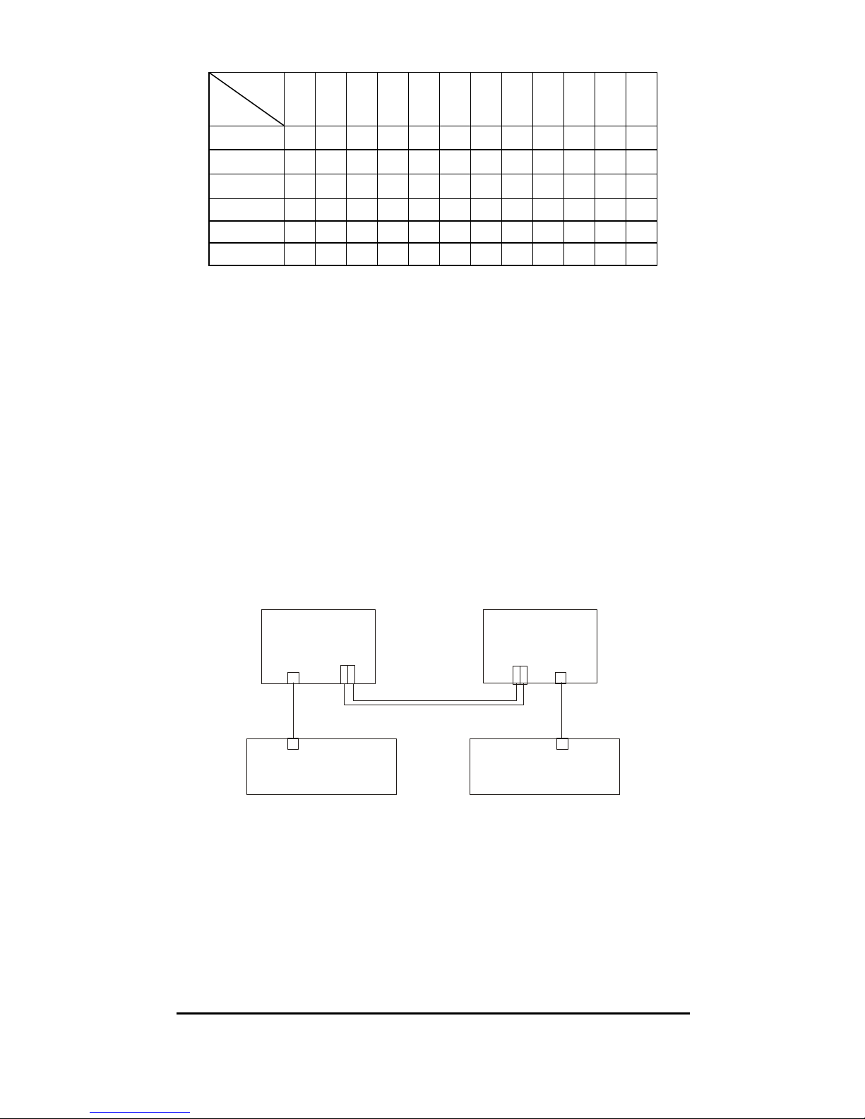
Link
Status
Disconnect
Link 1 Link 2 Link 3 Link 4 Link 5 Link 6 Link 7 Link 8
Link
Fail 1
LED
Link
Fail 2
LED
Link
Fail 3
LED
Link
Fail 4
LED
Cable 1 On On On On Off On On On Off Off Off Off
Cable 2 Off On On On Off On On On On Off Off Off
Cable 3 On On On On On Off On On Off Off Off Off
Cable 4 On On Off On On On On On Off Off On Off
Cable 5 On Off On On On On Off On Off On Off Off
Cable 6 On On On Off On On On Off Off Off Off On
Note: When using two converters, don’t enable the both
device’s LLR function at the same time.
LLCF (Link Loss Carry Forward)
When a device connected to the converter and the TP line loss
the link, the converter’s fiber will disconnect the link of
transmit, so that the other ends will know that there is a
linkage error on this end. And when the Fiber line loss the
link, the converter’s TP will disconnected, and the other end
will know that there is linkage problem exist.
The switch 6 is to enable or disable the LLR function of the
media converter.
TX R X
Swit c h B
Swit c h A
Cable 3
Cable 2
Cable 4
Cable 1
Media
Converter B
Med ia
Conver ter A
TX RX
LLCF Off
LLR Off
LLCF On
LLR Off
LINK 6
Copper
LINK 5
Copper
Copper
LINK 4
LINK FAIL 4
Fiber
LINK 3
LINK FAIL 3
Fiber
LINK 1
LINK FAIL 1
Copper
LINK 2
LINK FAIL 2
The table below shows the status happens when LLCF
function is working through two ways of connection:
9
Page 10
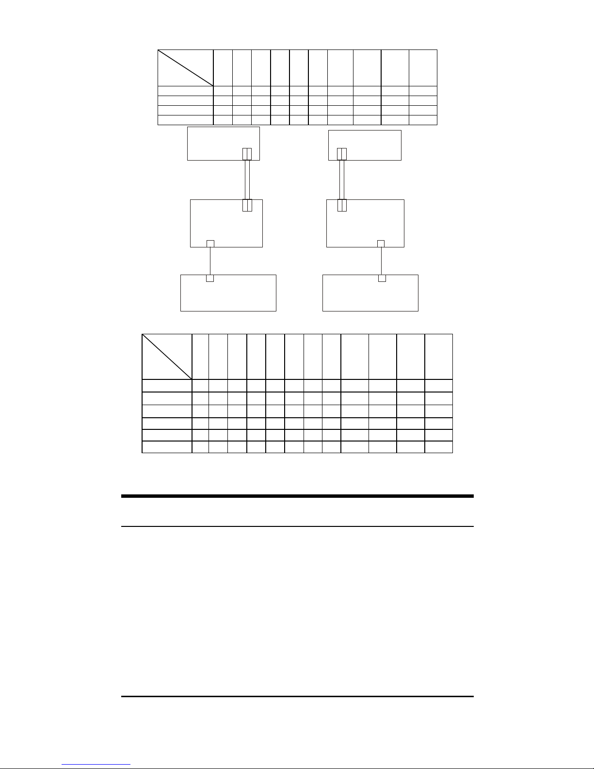
Link
Status
Disconnect
Link 1 Link 2 Link 3 Link 4 Link 5 Link
6
Link
Fail 1
LED
Link
Fail 2
LED
Link
Fail 3
LED
Link
Fail 4
LED
Cable 1 On On Off On On On Off Off On Off
Cable 2 Off Off On On Off On On Off Off Off
Cable 3 On On On Off On Off Off Off Off On
Cable 4 On Off Off On Off On Off On On Off
Fib er
Copper
TXRX
Fiber
Copper
Swit c h C
Swit c h D
LIN K 8
LINK 3
LIN K 1
LINK 7
Cable 4
Cable 1
Cable 3
Cable 2
Media
Converter B
Media
Converter A
LIN K 2
LIN K 4
LINK FAIL 4
LINK FAIL 3
LINK FAIL 1
LINK FAI L 2
LLCF Off
LLR Off
LLCF On
LLR Off
Fiber
TX RX
Fiber
LIN K 6
LINK 5
Swit c h A
Swit c h B
TXRX
TX R X
Cable 6
Cable 5
Copper
Copper
Link
Stat
us
Disconnect
Link 1 Link 2 Link 3 Link 4 Link 5 Link 6 Link 7 Link
8
Link
Fail 1
LED
Link
Fail 2
LED
Link
Fail 3
LED
Link
Fail 4
LED
Cable 1 On On On On Off On On On Off Off Off Off
Cable 2 Off Off On On On On Off On On Off Off Off
Cable 3 On On On On On Off On On Off Off Off Off
Cable 4 On On Off On On On On On Off Off On Off
Cable 5 On Off On On Off On Off On Off On Off Off
Cable 6 On On On Off On On On Off Off Off Off On
Dual Wavelength Single Fiber
The converter combine transmit and receive signal onto one
fiber strand using two kind of wavelength. The units on both
ends of a link are different. One module uses one wavelength
to transmit and a second wavelength to receive, while the
other module flips that relationship. For this reason these
units are sold in pairs.
10
Page 11
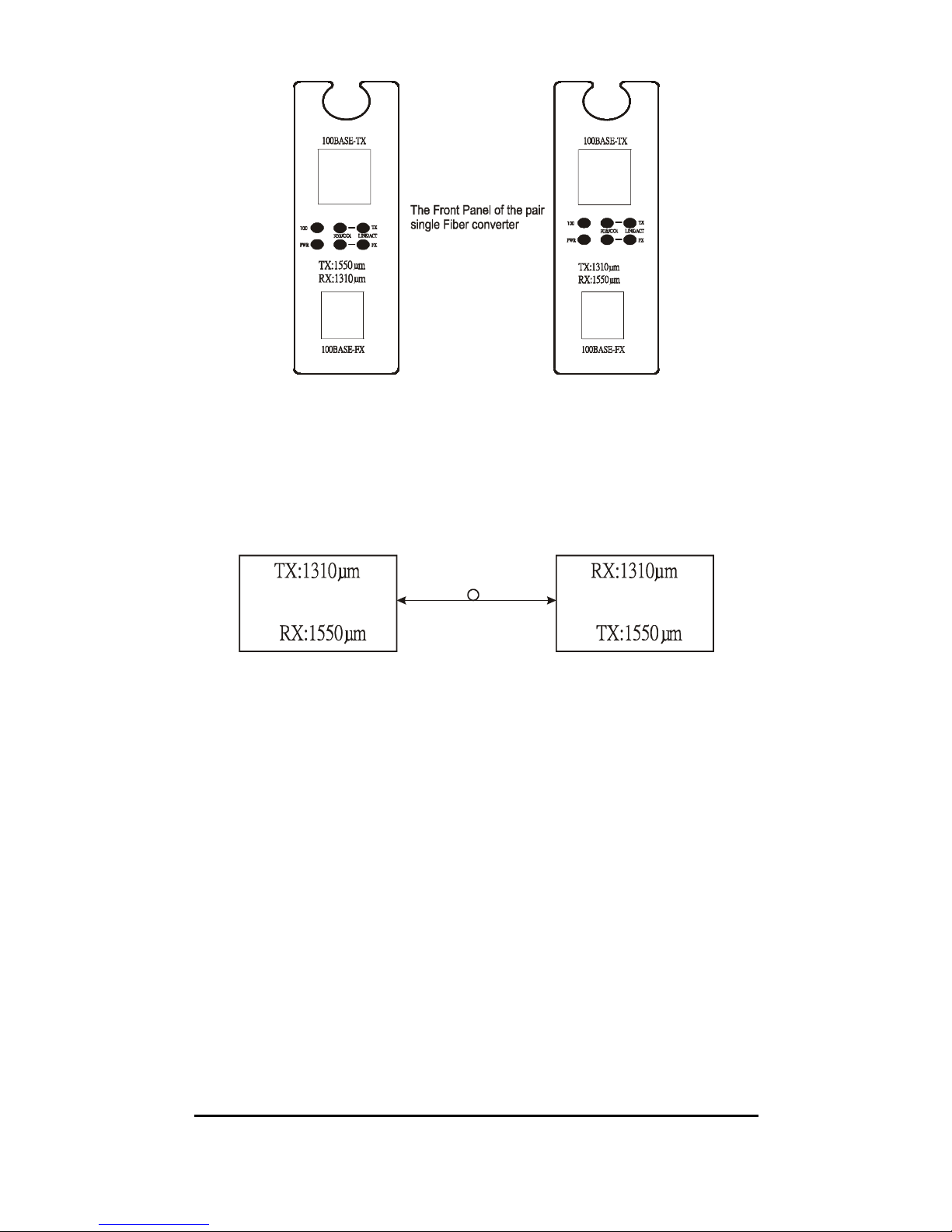
When using a DMC-920R that the TX(transmit) is 1310µm
and the RX(receive) is 1550µm, then the other end need to
have a combination of DMC-920T that the TX(transmit) is
1310µm and the RX(receive) is 1550µm.
The TX needs to connect to the other end’s RX with the same
wavelength.
Media Converter #1
Media Converter # 2
There is a two pin DIP switch on the module which define as
switch 1 and switch 2:
Switch 1: Fiber mode switch
When the switch was turned to “On”, it means that the fiber
was turned to forced mode, and “Off” for auto-negotiation
mode.
Note: Be sure the opposite end is using the same setting(forced or
Auto-negotiation). And when using two converters at the same
time, the two converters MUST set to forced mode.
Switch 2: LLR
When the switch was turned to “On”, it means that the
LLR was enabled and “Off” for disabled.
Note: When using two converters at the same time, then only one
converter need to enable the LLR function.
11
Page 12
12
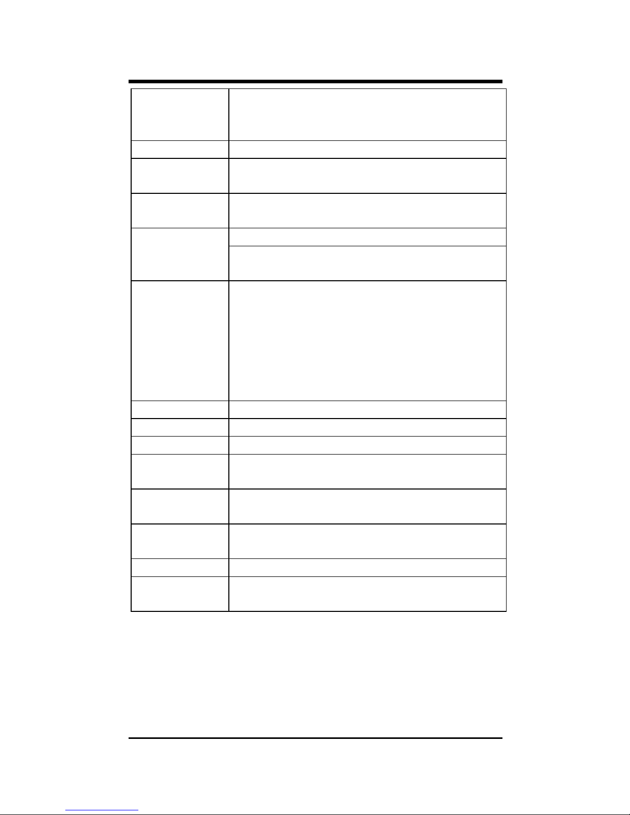
SPECIFICATIONS
Applicable
Standards
IEEE 802.3 10BASE-T
IEEE802.3u 100BASE-TX &
100BASE-FX
Fixed Ports 1 TX port, 1 Single Fiber FX port
Speed 10/20Mbps for half/full-duplex
100/200Mbps for half/full-duplex
Forwarding
rate
148,800pps
Per Unit- (2 LEDs): Power; Speed( 100 ) LED
Indicators
Per Port- (2 LEDs): FDX/COL,
LINK/ACT
Cable 10BASE-T –
2-pair UTP Cat. 3,4,5, up to 100 m (328 ft)
100BASE-TX --
2-pair UTP Cat. 5, up to 100 m (328 ft)
100BASE-FX --
9/125 single-mode fiber optic cable, up to
20 km
Dimensions L120 × W88 × H25 mm
Weight 305 g
Power External power adaptor 7.5V 1.5A
Power
Consumption
7.2W Max.
Operating
Temperature
0°C ~ 40°C (32°F ~ 104°F)
Storage
Temperature
-25°C ~ 70°C (-13°F ~ 158°F)
Humidity 10 ~ 90%, non-condensing
Emissions FCC part 15 Class B, CISPR ClassB, VCCI
Class B, CE Mark
 Loading...