

Page 1
DMC-805X
10G CX4 To 10G SFP+
Media Converter
Version 1.00Version 1.00
Page 2

2
FCC Class A Certification
This equipment has been tested and found to comply with the
limits for a Class A digital device, pursuant to Part 15 of the
FCC Rules. These limits are designed to provide reasonable
protection against harmful interference when the equipment is
operated in a commercial environment. This equipment
generates, uses, and can radiate radio frequency energy and, if
not installed and used in accordance with this user’s guide, may
cause harmful interference to radio communications. Operation
of this equipment in a residential area is likely to cause harmful
interference, in which case the user will be required to correct the
interference at his own expense.
CE Mark Warning
This is a Class A product. In a domestic environment, this
product may cause radio interference, in which case the user may
be required to take adequate measures.
VCCI Class A Compliance (Japan)
This is a product of VCCI Class A Compliance
Page 3

3
Introduction
Thank you for choosing the DMC-805X, a 10G CX4 to
10G SFP+ Media Converter. The DMC-805X` converts
10G CX4 signals to 10G fiber signals. Comes with an
SFP+ slot for user-selectable fiber transceivers and
extends the network connection to various lengths
depending on SFP+ transceiver capability.
About DMC-805X
The DMC-805X is a high performance 10G media
converter which is flexible for distance extension on a
server equipped with CX4 NIC or previous 10G switch
built with 10G CX4 ports.
The DMC-805X can be used as standalone converter or
installed in D-Link special designed chassis (DMC-1000).
A management option is available for the DMC-805X
installed in the chassis (DMC-1000). The management
module (DMC-1002) lets users monitor in real-time the
status of DMC-805X and power supplies in the chassis. It
also sends out alarms to alert users of abnormal situations.
Management follows industry standards, including SNMP
and http, allowing users to monitor and manage from a
third-party SNMP management workstation or via a web
browser.
Page 4

4
Product Features
Compliance with IEEE802.3ak CX4 XAUI and
IEEE802.3ae/aq 10GBASE SFP+
One-channel media conversion between
10GBASE-CX4 and 10GBASE-SR/ER/LR/LRM/ZR
SFP+ module
Extends network connection to various lengths
depending on SFP+ transceiver capability
Used as stand-alone converter or installed in D-Link
special designed chassis (DMC-1000)
Provides intelligent functions such as LLR (Link Loss
Return) and LLCF (Link Loss Carry Forward)
Front panel status LEDs
Hot-swappable when installed in a standard
rack-mount chassis (DMC-1000)
Installation
This chapter gives step-by-step installation instructions
for the DMC-805X.
Selecting a Site for the Equipment
As with any electric device, you should place the
equipment where it will not be subjected to extreme
temperatures, humidity, or electromagnetic interference.
Specifically, the site you select should meet the following
requirements:
Page 5

5
1. The ambient temperature should be between 32 and
104 degrees Fahrenheit (0 to 40 degrees Celsius).
2. The relative humidity should be less than 90 percent,
non-condensing.
3. Surrounding electrical devices should not exceed the
electromagnetic field (RFC) standards for IEC 801-3,
Level 2 (3V/M) field strength.
4. Make sure that the equipment receives adequate
ventilation. Do not block the ventilation holes on each
side of the switch or the fan exhaust port on the side or
rear of the equipment.
5. The power outlet should be within 1.8 meters of the
switch.
Connecting to Power
1. The DMC-805X is a plug-and-play device.
2. Connect the supplied AC to DC power adaptor with a
power voltage of 12Vdc/0.5Amp to the DC-Jack on
the converter, and then attach the plug into a standard
AC outlet.
Installing in a Chassis
The DMC-805X can be fit into any of the expansion slots
on D-Link special designed chassis (DMC-1000).
Page 6
6
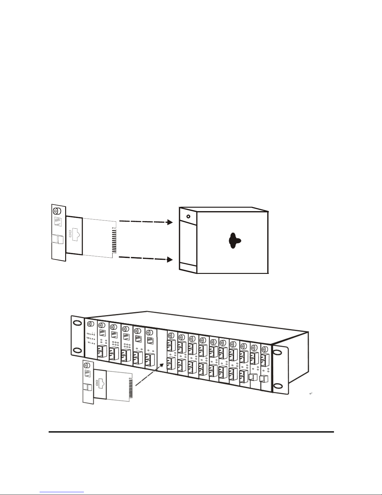
Follow up the following steps to install the
converter onto a carrier supplied with D-Link
special designed chassis (DMC-1000):
Step 1- Unscrew and pull out the media converter board.
(Refer to figure 1)
Step 2- Plug in the media board to any of the vacant
slot. (Refer to figure 2)
Step 3- Fit the converter onto the carrier and use the
screw to secure it.
Figure 1
Figure 2
Page 7
7
Monitoring the Converter through Management
Module (DMC-1002)
There is a management module named as DMC-1002
that can control this media converter through D-Link
special designed chassis system (DMC-1000), this media
converter can be controlled through Web Browser, SNMP
and terminal emulation program.
The management module will detect the default reset on
the DIP switches and display out the status, also the
management module (DMC-1002) can control the
function through the chassis system (DMC-1000).
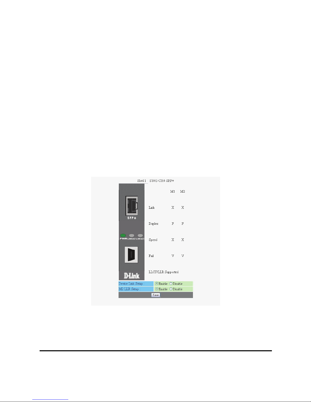
Figure 3 is a captured screen of DMC-805X from the
Web GUI.
Figure 3
NOTE: To control the function in a working station, need to collocate together with optional
Chassis System and Management Module.
Page 8
8
LED Indicator
The LED indicators give you instant feedback on status of
the converter:
LEDs State Indication
Lights on Power on
PWR
(Power)
Lights off Power off
Lights on Linking
Lights Blinking Data transmitting and receiving
CX4
Lights off Not Linking
Lights on Linking
Lights Blinking Data transmitting and receiving
SPF+
Lights off Not Linking
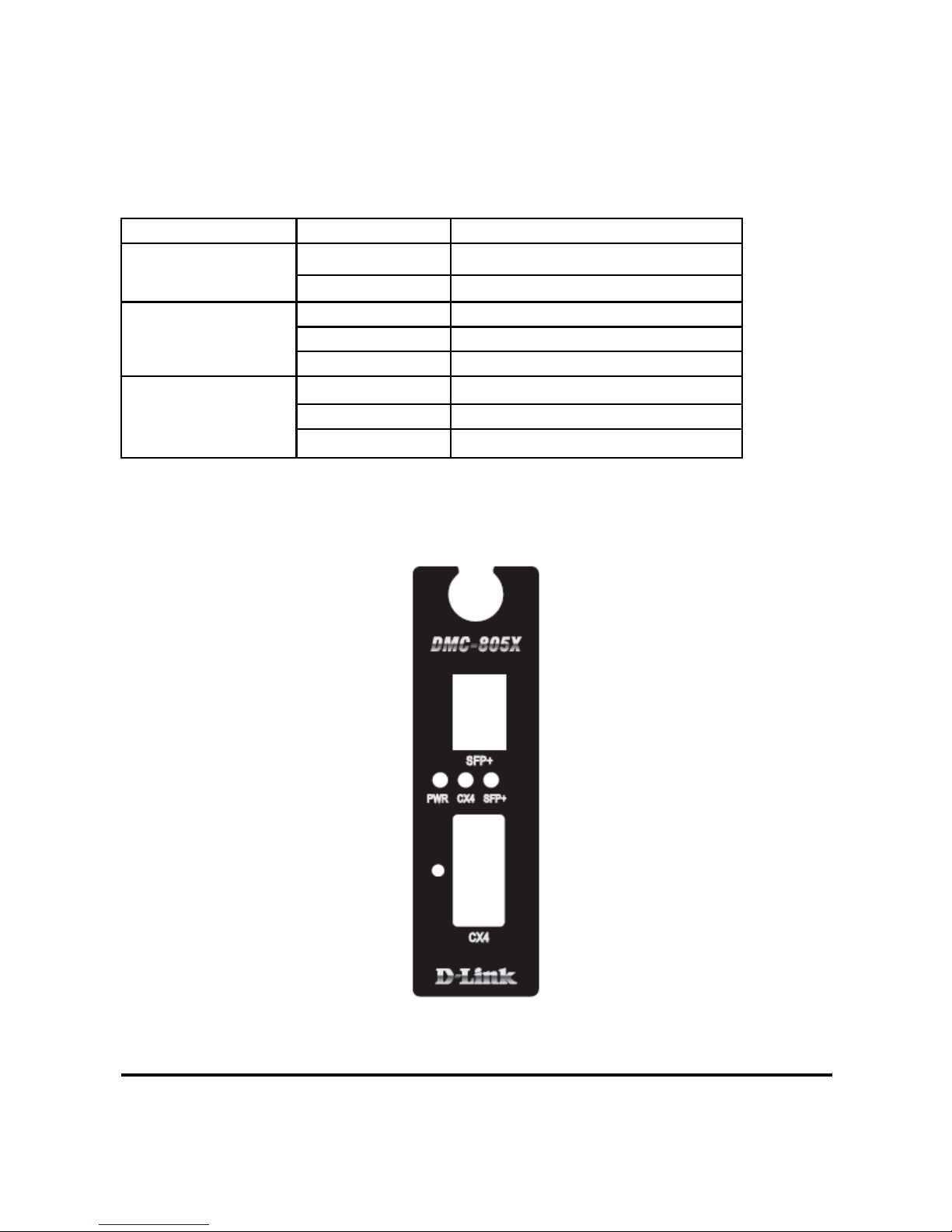
Refer to figure 4 to check the LED location on the front
panel.
Figure 4
Page 9
9
Link Pass Through Function
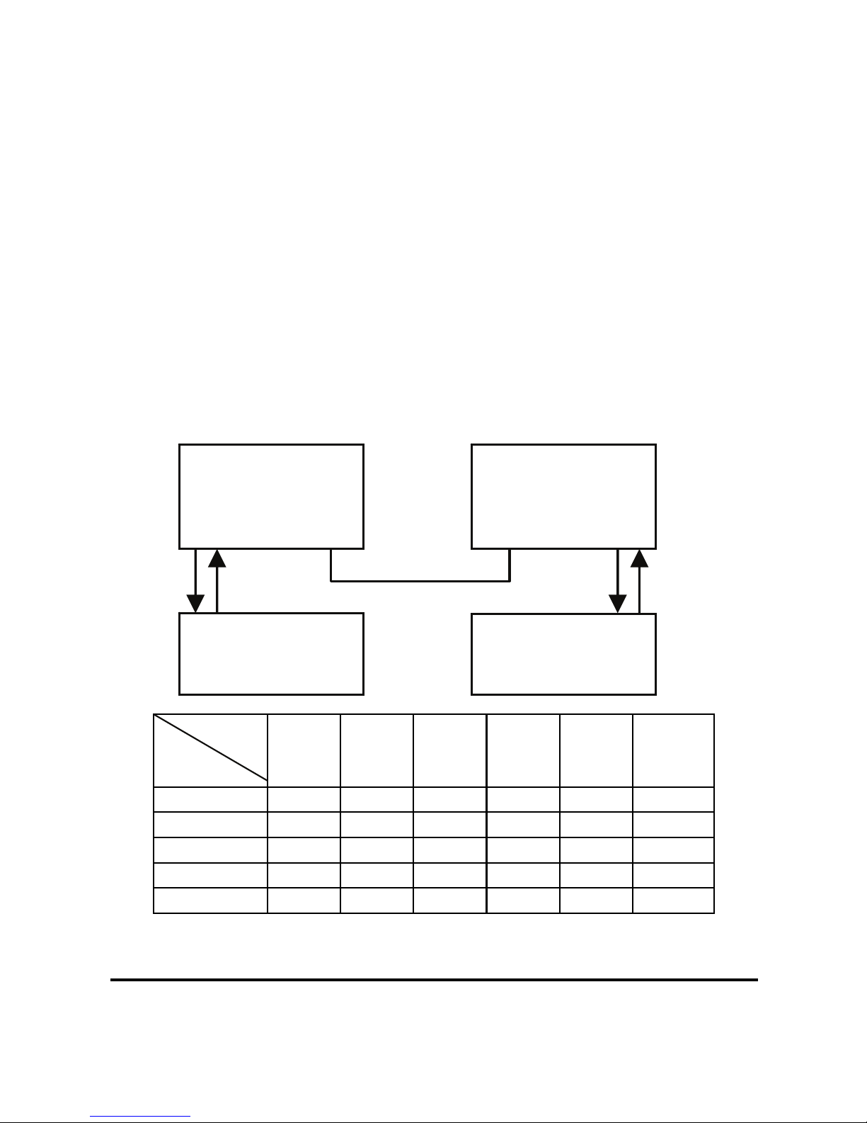
(LLCF) Link Loss Carry Forward
When a device connected to the converter and the CX4
XAUI lost the link connection, the converter’s fiber will
disconnect the link of transmit, so that the other ends will
know that there is a linkage error on this end. And when
the Fiber line lost the link, the converter’s CX4 XAUI
will be disconnected, and the other end will know that
there is linkage problem exist.
The LLCF setting is always Enable on this converter.
The table below shows how LLCF function is working:
Link Status
Disconnect
Link 1 Link 2 Link 3 Link 4 Link 5 Link 6
Cable 1 Off On On On On Off
Cable 2 Off Off On Off On Off
Cable 3 Off On Off On Off Off
Cable 4 Off On On On On Off
Cable 5 Off On Off Off On Off
DMC-805X #2
Link4
CX4
Link5
SFP+
DMC-805X #1
Link2
SFP+
Link3
CX4
RX TX
Link1
10GbE Switch
RX TX
Link6
10GbE Switch
cable2 cable1 cable4 cable3
cable5
TX RX TX RX
Page 10
10
Link Pass Through Function
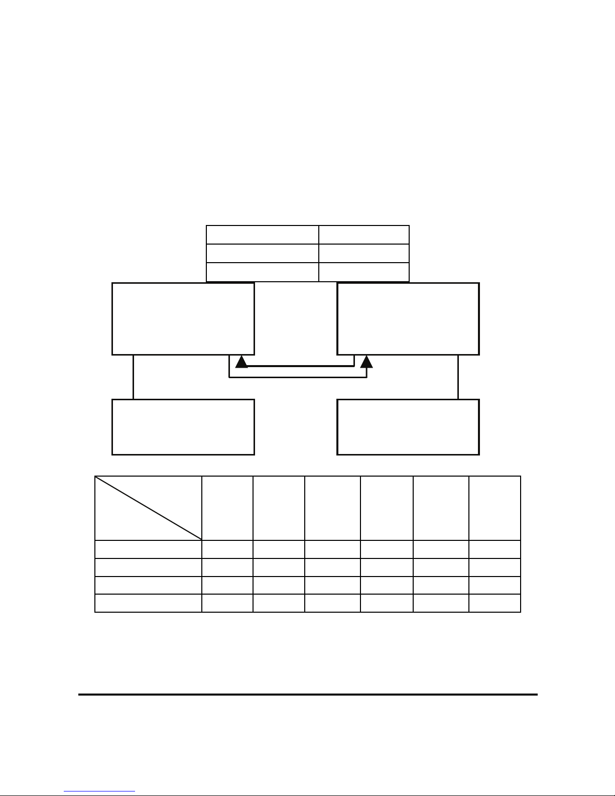
(LLR) Link Loss Return
When a device connected to the converter and the fiber
line lot the link, the converter’s fiber will disconnect the
link of transmit.
There is a switch to enable or disable the function of the
media converter.
The table below shows how LLR function is working:
Media Converter LLR
A ON
B OFF
Link Status
Disconnect
Link 1 Link 2 Link 3 Link 4 Link 5 Link 6
Cable 1
Off On Off Off On Off
Cable 2
Off On On Off On Off
Cable 3
Off Off On Off On Off
Cable 4
Off On Off Off Off Off
NOTE: If connecting two converters with LLR function in both end, it is recommended that the
monitor end converter had to turn off the LLR function, and turn on the LLR function of the
remote end
converter.
DMC-805X #1
Link2
CX4
Link3
SFP+
TX RX
DMC-805X #2
Link4
SFP+
TX RX
Link5
CX4
Link1
PC
Link6
PC
cable1
cable3
cable4
cable2
Page 11
11
Switch
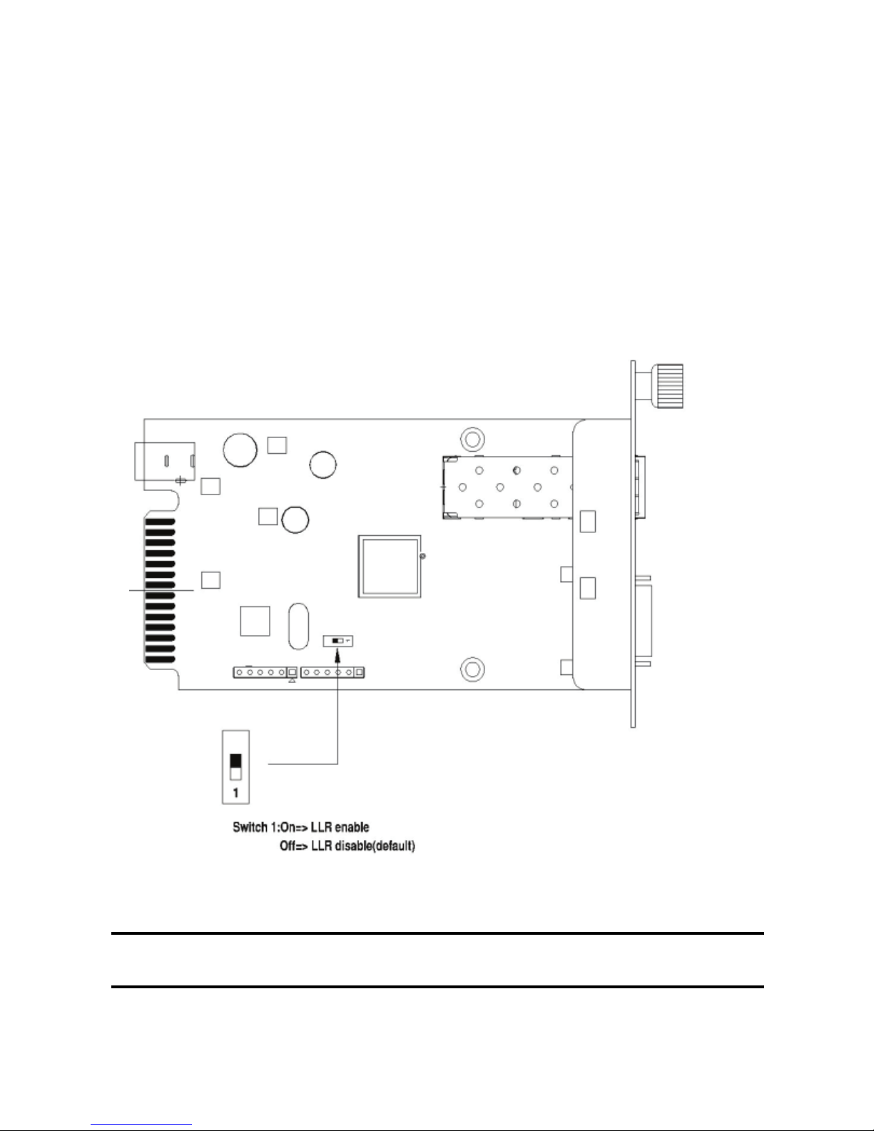
There is one pin DIP switch on the module which defines
as switch 1:
Switch 1: LLR
When the switch was turned to “On”, it means that the
LLR was enabled and “Off” for disabled.
Note: When using two converters, don’t enable the both devices’ LLR function at
the same time.
Figure 5
Page 12

12
Specifications
Standards:
IEEE802.3ak 10GBASE-CX4
IEEE802.3ae/aq 10GBASE-SR/ER/LR/LRM/ZR
Data Transfer Rate:
20Gbps
Duplex Mode:
Full Duplex Mode
LED indicators: PWR, CX4, SFP+
Supported SFP+
Transceivers
DEM-431XT:
10GBASE-SR SFP+ Transceiver (w/o DDM), 80m:
OM1 & OM2 MMF,300m: OM3 MMF
DEM-431XT-DD:
10GBASE-SR SFP+ Transceiver (with DDM), 80m:
OM1 & OM2 MMF, 300m: OM3 MMF
DEM-432XT:
10GBASE-LR SFP+ Transceiver (w/o DDM), 10km
DEM-432XT-DD:
10GBASE-LR SFP+ Transceiver (with DDM), 10km
DEM-433XT:
10GBASE-ER SFP+ Transceiver (w/o DDM), 40km
DEM-433XT-DD:
10GBASE-ER SFP+ Transceiver (with DDM), 40km
DEM-434XT:
10GBASE-ZR SFP+ Transceiver (w/o DDM), 80km
DEM-435XT:
10GBASE-LRM SFP+ Transceiver (w/o DDM), 220m:
OM1 & OM2 MMF, 300m: OM3 MMF
DEM-435XT-DD:
10GBASE-LRM SFP+ Transceiver (with DDM),
220m: OM1 & OM2 MMF, 300m: OM3 MMF
DEM-436XT-BXU:
10GBASE-LR BiDi SFP+ Transceiver (w/o DDM),
20km, TX: 1270nm, RX: 1330nm
DEM-436XT-BXD:
10GBASE-LR BiDi SFP+ Transceiver (w/o DDM),
20km, TX: 1330nm, RX: 1270nm
Page 13

13
CX4 Cable 10GBASE-CX4 XAUI 4-lane PCS (Clause 48) and
copper cabling similar to that used by InfiniBand
technology, up to 15m
DIP Switch Bit 1:
Off: LLR disable(default)
On: LLR enable
Dimensions L120 × W88 × H25 mm
Power External power adapter 12V/0.5A
Temperture:
Storage: -10°C ~ 70°C (14 ~ 158º F)
Operating: 0°C ~ 40°C (32°F ~ 104°F)
Humidity: 10% ~90% non-condensing
Power Consumption: 3.4 Watts Max.
EMI Compatiblity: FCC part 15 Class A
CE Certification, Class A
VCCI Class A
Page 14

14
Notes
Page 15

15
Notes
Page 16

Ver. 1.00(WW)
2012/03/29
29071600DM805X0
 Loading...