

D-Link DIS-700G‑28XS Service Manual
DIS-700G-28XS Industrial Layer 2+ Gigabit Managed Switch with 10G SFP+ slots Quick Installation Guide
Item
Quantity
DIS-700G-28XS
Industrial Layer 2+ Gigabit Managed Switch
with 10G SFP+ slots
Quick Installation Guide
This document provides basic installation instructions for the DIS-700G-28XS.
Package Checklist
Please verify that the box contains the following items:
Rack-mountable Ethernet switch 1
Rack-mounting brackets 2
Screws for mounting brackets 4
Console cable 1
ALM terminal block (2-pin) 1
Quick Installation Guide 1
SFP Ethernet port dust covers 2~14
Safety Instructions
When a connector is removed during installation, testing, or servicing, or when an energized fiber is
broken, a risk of ocular exposure to optical energy that may be potentially hazardous occurs,
depending on the laser output power.
The primary hazards of exposure to laser radiation from an optical-fiber communication system are:
Damage to the eye by accidental exposure to a beam emitted by a laser source.
Damage to the eye from viewing a connector attached to a broken fiber or an energized fiber.
1
DIS-700G-28XS Industrial Layer 2+ Gigabit Managed Switch with 10G SFP+ s lots Quick Ins tallation Guide
DIS-700G-28XS
①
②
④
⑤
⑥
③
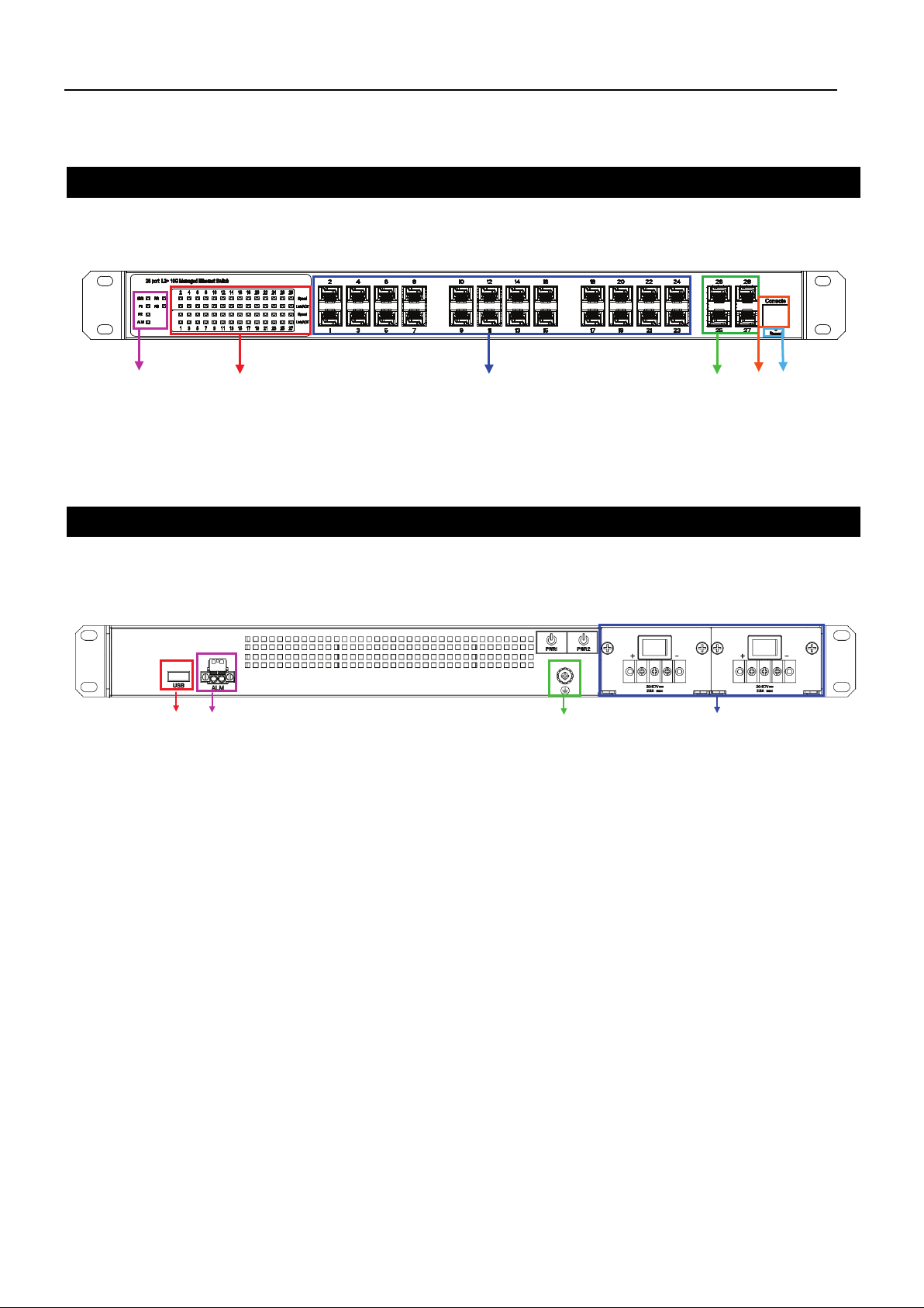
① System status LED indicators
②
③
④
⑤
⑥ Reset button
❶ ❷ ❸
❹
❶ USB port
PWR1 & PWR2 terminal blocks for dual DC power input
GP800980X-000
Model Layouts
Front View
Port status LED indicators
Ports 1-24: 100/1000 Mbps SFP slots
Ports 25-28: 10G SFP+ slots
Console port
❷ Terminal block for Alarm Relay output
❸ Grounding screw
❹
Rear View
DIS-700G-28XS
2
DIS-700G-28XS Industrial Layer 2+ Gigabit Managed Switch with 10G SFP+ s lots Quick Ins tallation Guide
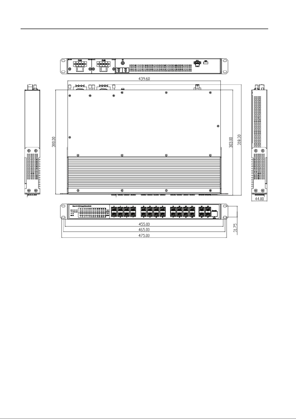
Dimensions
(unit = mm)
3
DIS-700G-28XS Industrial Layer 2+ Gigabit Managed Switch with 10G SFP+ s lots Quick Ins tallation Guide
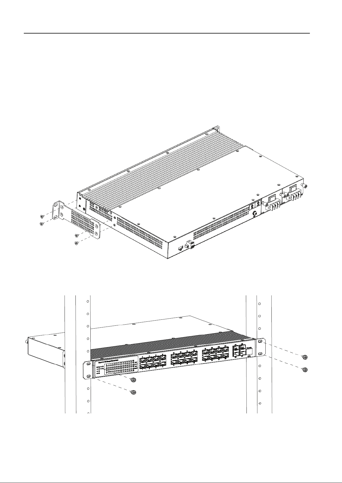
Rack Mounting
When mounting the switch, practice good safety habits. Relay rack mounting normally requires at least
two people.
1. Obtain the tools required for the mounting hardware.
2. Attach the mounting brackets to the switch using the screws in the accessory kit.
3. Place the switch in its relay location and secure it to the rack.
Mounting Bracket Position for Standard Mount
4
DIS-700G-28XS Industrial Layer 2+ Gigabit Managed Switch with 10G SFP+ s lots Quick Ins tallation Guide
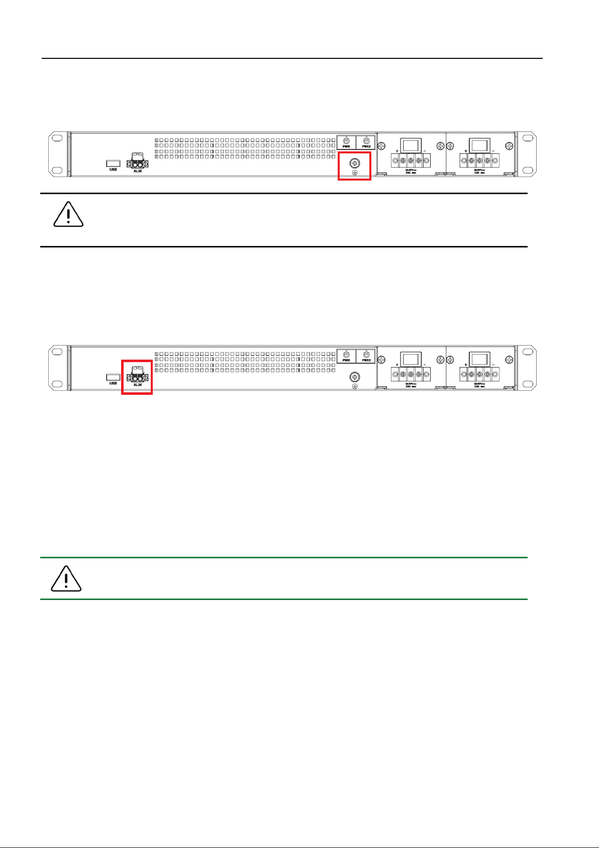
Warning:
The middle grounding pin of the DC power terminal block has no function. The device
Note:
The DC power should be connected to a properly-fused power supply.
Ground Connecting
The DIS-700G-28XS must be properly grounded for optimum system performance.
can only be grounded using the dedicated grounding screw.
Alarm Relay Connecting
The 24 V DC / 2 A alarm relay output contacts are located in a separate 2P terminal block. The alarm
relay contact is “Normal Open”, and will automatically close when a power failure is detected.
Power Connecting
DC Power Connection
The switch can be powered using two power supplies (input range 20 V – 57 V) through the 3P
terminal block for DC power. Insert the positive and negative wires into the V+ and V- contacts on the
terminal block and tighten the wire-clamp screws to prevent the wires from being loosened.
After completing chassis installation, please apply power to the fused power distribution panel feeding
the chassis.
5
 Loading...