


Quick Installation Guide
Wireless AC1200 Wave 2 Industrial
Outdoor Access Point
DIS-3650AP
Additional documentation is also available on the D-Link website


Before You Begin
System Requirements
This installation guide provides instructions
for installing the DIS-3650AP on your network.
Additional documentation is also available on
the D-Link support website.
• Nuclias Connect Manual: For additional
information and instructions on how
to configure the device using Nuclias
Connect.
• DIS-3650AP User Manual: For additional
information and instructions on how to
configure the device using the web user
interface.
Package Contents
This DIS-3650AP package includes the following
items:
• DIS-3650AP Access Point
• Quick Start Guide
• Mounting kit (Wall/Pole/DIN Rail Mount)
- Articulation Pole x 1
- T-form Bracket x 1
- M8x40 Screw Bolts x 1
- M6 Screw x 4
- M8 Nut x 1
- Washer (M8 x 1 ; M6 x 4)
- Spring Washer (M8 x 1 ; M6 x 4)
- Stainless Hose Clamp x 2
- Anchors plastic screws x 4
- Stainless screws x 4
- DIN Rail mounting kit
If any of the above items are damaged or
missing, please contact your local D-Link reseller.
Note: To power the unit, use an 802.3at PoE
Switch or PoE Injector.
• Computers with Windows®, Macintosh®,
or Linux-based operating systems with an
installed Ethernet Adapter
Hardware Overview
LED Indicators
1
2
3
4
Figure 1: Side Panel LED
# LED Description
Green (Solid) - Device operational
Power/
1
2 2.4
3 5G
4
Red (Flashing) - Device booting up/
Status
Device malfunctioned
Red (Solid) - Device boot up has failed
Solid green - 2.4GHz is enabled
Blinking green - data transmission
Solid green - 5GHz is enabled
Blinking green - data transmission
Indicates whether a device is
LAN
connected to LAN and receiving
(PoE)
power on the PoE port.
Table 1: LED Description
ENGLISH
DIS-3650AP Quick Installation Guide
1

Interface Connectors
# Connector Description
DIN rail
1
Adapter
Wall/Pole
2
Grounding
3
Mount
Connect DIN rail kit to mount it
on DIN-Rail.
Mount to connect to the mounting
plate on a wall or a pole.
Connector for the grounding wire.
Wire
Table 3: Interface Description
ENGLISH
# Connector Description
1 LAN(PoE)
2 CONSOLE
3 Reset
1 2 3
Figure 2: Top Connectors
Gigabit RJ-45 port for data and
Power over Ethernet (PoE) power.
Connect an RJ-45 Ethernet console
for CLI control (Option)
Press and hold for 10 seconds to
factory reset the device
Table 2: Interface Description
1
Installation
Using Power over Ethernet (PoE)
1. Use a standard Ethernet cable to connect
the LAN(PoE) port on the DIS-3650AP to
a PoE power source device such as an
802.3at PoE switch or PoE injector.
Conguration
Using Nuclias Connect
The DIS-3650AP is designed to be managed
through Nuclias Connect. Refer to the Nuclias
Connect Manual for detailed configuration
instructions.
Note: D-Link recommends manually configuring
the device before mounting it.
Nuclias Connect App Conguration
1. Download the free Nuclias Connect app
2
from the App Store or Google Play by
searching for Nuclias Connect or by
scanning the QR code below.
3
Figure 3: Back Connectors
2
DIS-3650AP Quick Installation Guide

2. Open the Nuclias Connect app and follow
the onscreen instructions to discover and
set up your device.
Connect an Ethernet Cable to the LAN(PoE) port
on the DIS-3650AP. Use the LAN Port Waterproof
Enclosures to seal the ports.
Manual Conguration
Note: The management computer, DHCP server
and DIS-3650AP must be in the same subnet.
Use one of the following methods to access the
web user interface:
Connecting through Ethernet
1. Use an Ethernet cable to connect the
DIS-3650AP to the switch or router the
management computer is connected to.
2. Manage the access point from a computer.
Enter dis3650ap.local in the address field
of your browser.
3. Log in to the administration user
interface. The default login information is
Username: admin
Password: admin
Connecting Wirelessly
1. Connect the management computer to
the default SSID of the DIS-3650AP, “dlink”.
2. Manage the access point from a computer.
Enter dis3650ap.local in the address field
of your browser.
3. Log in to the administration user
interface. The default login information is
Username: admin
Password: admin
Install Enclosure Onto The Articulation
Pole
Attach the articulation pole to back of AC using
M5x16 screws & washers.
Figure 5
Installation for Wall
Fix the T-from Bracket to the wall by using the
wood / gyprock screws.
ENGLISH
Mounting
Figure 4: LAN Port Waterproof Enclosure
DIS-3650AP Quick Installation Guide
Figure 6
3

Installation for Pole
Mounting for Recommended Pole Dia.:
1.5~2”(38.1~50.8mm)
(A)
Mounting for Pole 1~ 3”
(25.4~76.2mm)
Fix the T-from Bracket to the pole by using the
stainless hose clamp.
ENGLISH
Figure 7
(A) The diameter of the Pole is too large Will result
in the failure to install smoothly, the diameter is
too small and the clamping force is insufficient.
* Pole diameter Max.: 2.1”(53.3mm)
Min.: 1.0”(25.4mm)
(B) To minimize bolts crosstalk, the bolts should
gradually increasing load and parallel tighten.
(B)
Figure 8
Install Articulation Pole with The
T-formed Bracket
After finishing the previous two steps, fix the
articulation pole to the T-formed bracket by
using M8x40 bolts, nut, spring washer and
washer.
Figure 9
4
DIS-3650AP Quick Installation Guide

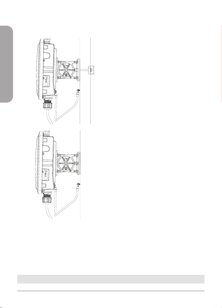
Installation for DIN Rail
The DIS-3650AP can be mounted on a standard
DIN rail using the included DIN mounting kit.
Use the following instructions to install the DIS3650AP on a rail:
1. Install a Din rail kit on enclosure. Check that
the DIN rail kit is installed properly using
two screws on each end.
Figure 10
2. Position the DIS-3650AP against the rail,
then tilt it upwards and hook the DIN rail
clip on the back of the device against the
rail. Snap the device into place to complete
the installation.
ENGLISH
Figure 12: Attaching the Grounding Wire
3. A grounding wire is to protect your device
from lightning strikes and the buildup of
static electricity. Attach the grounding
wire to the DIS-3650AP using the included
screw(M3.9 * 7.8 mm).
Figure 11
DIS-3650AP Quick Installation Guide
Figure 13: Attaching the Grounding Wire
5
4. Tighten the grounding wire (green-andyellow, 18AWG) to the DIS-3650AP until it
is securely attached.
ENGLISH
Professional installation instruction
1. Installation personal
This product is designed for specific application
and needs to be installed by a qualified personal
who has RF and related rule knowledge. The
general user shall not attempt to install or
change the setting.
2. Installation location
The product shall be installed at a location
where the radiating antenna can be kept
28cm from nearby person in normal operation
condition to meet regulatory RF exposure
requirement.
3. External antenna
Use only the antennas which have been
approved by the applicant. The non-approved
antenna(s) may produce unwanted spurious
or excessive RF transmitting power which
may lead to the violation of FCC limit and is
prohibited.
4. Installation procedure
Please refer to user’s manual for the detail.
5. Warning
Please carefully select the installation position
and make sure that the final output power does
not exceed the limit set force in relevant rules.
The violation of the rule could lead to serious
federal penalty.
Figure 14: Attaching the Grounding Wire
5. Attach the other end of the grounding wire
to either the wall or pole mount. Ensure
that the wall or pole mount is connected
to an electrical ground.
TECHNICAL SUPPORT dlink.com/support
6
DIS-3650AP Quick Installation Guide

Appendix - Statements
Federal Communication Commission Interference Statement
This device complies with Part 15 of the FCC Rules. Operation is subject to the following two conditions: (1)
This device may not cause harmful interference, and (2) this device must accept any interference received,
including interference that may cause undesired operation.
NOTE: This equipment has been tested and found to comply with the limits for a Class A digital device,
pursuant to part 15 of the FCC Rules. These limits are designed to pro-vide reasonable protection against
harmful interference when the equipment is operate din a commercial environment. This equipment
generates, uses, and can radiate radiofrequency energy and, if not installed and used in accordance with the
instruction manual, may cause harmful interference to radio communications. Operation of this equipment
in a residential area is likely to cause harmful interference in which case the user will be required to correct
the interference at his own expense.
FCC Caution:
• Any changes or modifications not expressly approved by the party responsible for compliance could
void the user’s authority to operate this equipment.
• This transmitter must not be co-located or operating in conjunction with any other antenna or
transmitter.
Radiation Exposure Statement:
This equipment complies with FCC radiation exposure limits set forth for an uncontrolled environment. This
equipment should be installed and operated with minimum distance 28cm between the radiator & your
body.
Note: The country code selection is for non-US model only and is not available to all US model. Per FCC
regulation, all WiFi product marketed in US must fixed to US operation channels only.
Déclaration d’exposition aux radiations
Cet équipement est conforme aux limites d’exposition aux rayonnements ISED établies pour un
environnement non contrôlé. Cet équipement doit être installé et utilisé avec un minimum de 0.28 m de
distance entre la source de rayonnement et votre corps.
ENGLISH
RED Compliance Statement
Compliance with 2014/53/EU Radio Equipment Directive (RED)
In accordance with Article 10.8(a) and 10.8(b) of the RED, the following table provides information on the
frequency bands used and the maximum RF transmit power of the product for sale in the EU:
Frequency range (MHz) Max. transmit power (dBm)
2412-2472 19.88 dBm
5500-5700 28.44 dBm
DIS-3650AP Quick Installation Guide
7

This equipment should be installed and operated with a minimum distance of 20 centimeters between
the radiator and your body.
Product and Warranty Information
To find out more about D-Link Nuclias product or marketing information, please visit the website http://
www.dlink.com or https://www.nuclias.com.
The D-Link Limited Lifetime Warranty information is available at
http://www.dlink.com/warranty
ENGLISH
1. Instructions for the installation of that conductor to building earth by a SKILLED PERSON.
2. Please contact the authorized distributor of D-Link for related accessories (Outdoor interconnection
cable, Cable Gland, Cable, etc.) for purchase and installation.
8
DIS-3650AP Quick Installation Guide

Notes

Notes

Notes

Notes


Ver. 1.00(WW)_130x183
2021/09/27
5300-00008121-01W
 Loading...