

D-Link DIS-200G-12S, DIS-200G-12SW Quick Installation Manual
Documentation is also available
on the D-Link website
This document will guide you through the
basic installation process for your new D-Link
Industrial Ethernet Switch.
DIS-200G Series
Quick Installation Guide
Industrial Ethernet Switch
Quick Installation Guide

1
ENGLISH
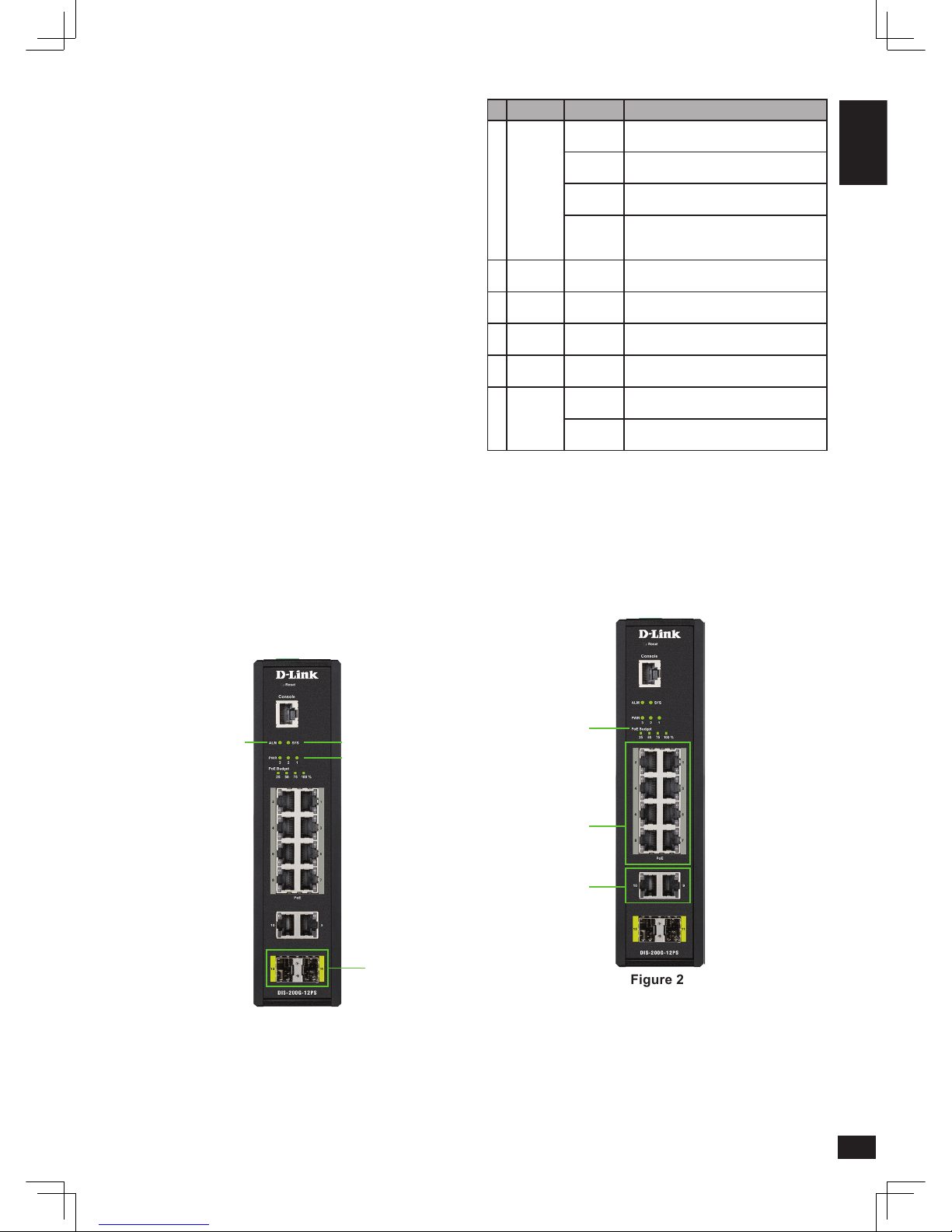
# LED Status Description
1 SYS
Solid
green
The DIS-200G is on and accepting web
connections.
Blinking
green
A rmware update is in progress.
Solid
amber
The DIS-200G is not ready for
communication.
Blinking
amber
The DIS-200G is booting up or PoE has
failed during system operation (DIS-200G12PS/PSW models only).
2 ALM
Solid
amber
The power supply to the DIS-200G has
failed.
3 PWR 1
Solid
green
Power source 1 is connected.
4 PWR 2
Solid
green
Power source 2 is connected.
5 PWR 3
Solid
green
Power source 3 is connected.
6
Ports
11 - 12
Solid
green
Port is connected at 1 Gbps.
Blinking
green
There is activity on the port at 1 Gbps.
Table 1
DIS-200G-12PS/PSW
Figure 2
Before You Begin
This Quick Installation Guide gives you step-bystep instructions for setting up the DIS-200G Series
Layer 2 Gigabit Industrial Smart Managed Switch.
The model you have purchased may appear slightly
dierent from the one shown in the illustrations. For
more detailed information about the switch, please
refer to the user manual.
Package Contents
This package should include the following items:
• DIS-200G Series switch
• DIN rail mounting kit
• Wall mounting kit
• User guide CD
• Quick Installation Guide
• Console cable
If any of the above items are damaged or missing,
please contact your local D-Link reseller.
Hardware Overview
LED Indicators
Figure 1
All Switches
1
6
3, 4, 5
2
1
2, 3
2
2
ENGLISH
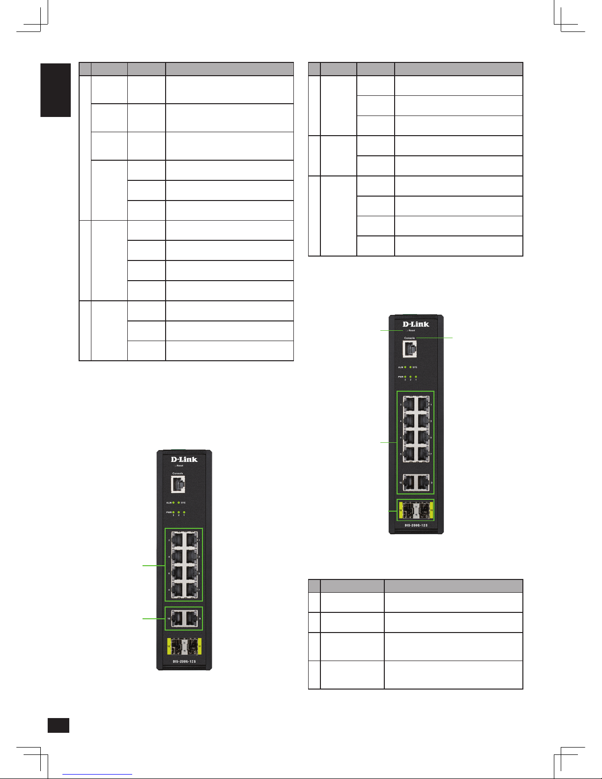
# LED Status Description
1
Left:
Ports 1 - 8
Solid
green
Port is connected at 1 Gbps.
Blinking
green
The port is undergoing cable diagnostics.
Solid
amber
Port is connected at 10/100 Mbps.
2
Right:
Ports 1 - 8
Blinking
green
There is activity on the port at 1 Gbps.
Blinking
amber
There is activity on the port at 10/100
Mbps.
3
Left:
Ports
9 - 10
Solid
green
Port is connected at 1 Gbps.
Blinking
green
There is activity on the port at 1 Gbps.
Solid
amber
Port is connected at 10/100 Mbps.
Blinking
amber
There is activity on the port at 10/100
Mbps.
Table 3
Front Panel Connectors
Figure 4
# Item Description
1 Reset
This is the reset button which is used to
perform a factory reset.
2 Console
This is a console port which is used to connect
to the DIS-200G using a RJ-45 to serial cable.
3 Ports 1 to 10
These are 10/100/1000 Mbps ports that can
be used to connect to any device using a
standard Category 5/5e RJ-45 Ethernet cable.
4 Ports 11 to 12
These are 1 Gbps SFP ports that can be used
to connect to other switches using compatible
SFP adapters and ber cable.
Table 4
# LED Status Description
1
PoE
Budget
100
Solid
green
The power budget is 100% and no PoE is
being used.
PoE
Budget
75
Solid
green
The power budget is between 100 and
75%.
PoE
Budget
50
Solid
green
The power budget is between 75 and 50%.
PoE
Budget
25
Solid
green
The power budget is between 50 and 25%.
Solid
amber
The power budget is between 25 and 0%,
but still has more than 15.4 W remaining.
Blinking
amber
The power budget is between 25 and 0%
and has less than 15.4 W remaining.
2
Left:
Ports
1 - 10
Solid
green
Port is connected at 1 Gbps.
Blinking
green
There is activity on the port at 1 Gbps.
Solid
amber
Port is connected at 10/100 Mbps.
Blinking
amber
There is activity on the port at 10/100
Mbps.
3
Right:
Ports 1 - 8
Solid
green
The PoE output is using IEEE 802.3af/at
and is less than 15.4 W.
Solid
amber
The PoE output is using IEEE 802.3at and is
between 15.4 and 30 W.
Blinking
amber
The PoE output on the port is over 30 W
and the port has been shut down.
Table 2
DIS-200G-12S/SW
Figure 3
4
3
1, 2
1
3
2
3
ENGLISH
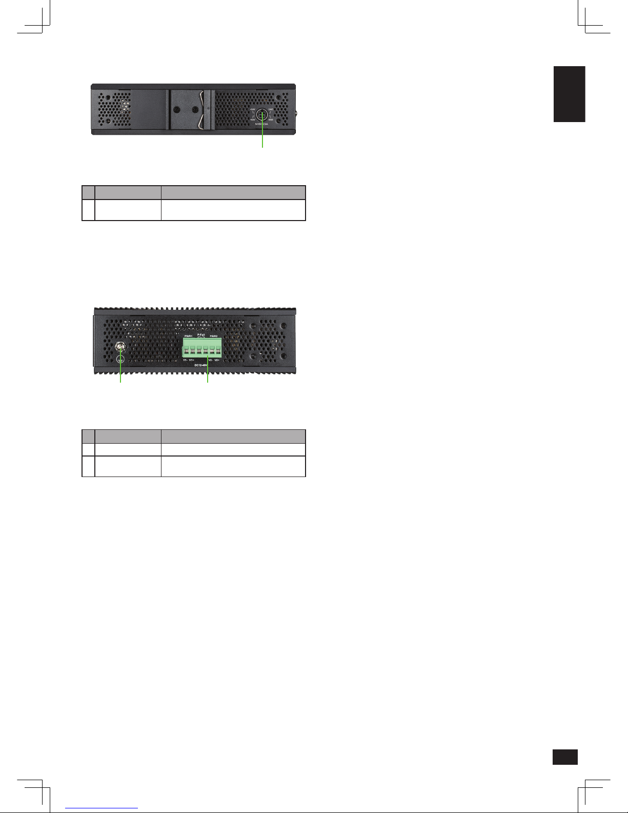
Rear Panel Connectors
Figure 5
# Item Description
1 Power input
This is used to connect an external power
adapter to the switch.
Table 5
Top Panel Connectors
Figure 6
# Item Description
1 Switch ground This is used to connect the switch to ground.
2 Terminal block
This is used to connect the switch to external
power sources and relays.
Table 6
Hardware Installation
Before You Begin
Observe the following precautions to help prevent
shutdowns, equipment failures, and personal injury:
• Install the DIS-200G in a cool and dry place. Refer
to the technical specications in the user manual
for the acceptable operating temperature and
humidity ranges.
• Leave at least 10 cm of space at the top, rear and
bottom of the switch for ventilation.
• Visually inspect the power connector and make
sure that it is fully secured to the power cord.
• Do not stack any devices on top of the switch.
It is also recommended that power and grounding
requirements are investigated before mounting the
DIS-200G, as access to the switch may be restricted
once it has been installed.
Mounting the Switch on a DIN Rail
Before beginning either mounting or removing the
DIS-200G from a DIN rail, please ensure that the
DIN rail is level and that the DIN rail mounting kit is
installed correctly on the DIS-200G.
Use the following instructions to install the DIS-200G
on a DIN rail:
1. With the back of the DIS-200G facing the DIN
rail, lower the top part of the rail mounting kit
onto the DIN rail.
2. Push the DIS-200G vertically down and rotate the
bottom of the DIS-200G towards the DIN rail, to
attach the switch to the DIN rail.
Use the following instructions to remove the
DIS-200G from a DIN rail:
1. Push the DIS-200G vertically down to create
enough space at the bottom of the rail mounting
kit to remove the DIS-200G from the DIN rail.
2. Rotate the DIS-200G upwards to remove the
bottom of the rail mounting kit from the rail, and
lift the DIS-200G upwards to remove the whole
of the switch from the DIN rail.
Mounting the Switch on a Wall
The DIS-200G can be installed on a solid surface by
using the included wall mounting plates attached
to the back of the switch. It can also be mounted
using the in-built screw hooks on the underneath
of the switch.
Using the Wall Mounting Brackets
Use the following instructions to install the DIS-200G
on a wall:
1. Remove the DIN rail mounting kit from the back
of the DIS-200G (if present).
2. Align the cross-section of the mounting plates
with the openings on the back of the switch and
secure the plates to the switch with the included
screws.
3. Place the switch with the mounting brackets
installed on the location where you want to
mount it, and use the mounting brackets as a
guide to mark where to drill the screw holes.
4. Drill holes on the marks and insert wall anchors
appropriate for the material of the wall.
1 2
1
 Loading...