

Page 1
DIS-200G Series Industrial Gigabit Ethernet Smart Managed Switch
Page 2

DIS-200G Series Industrial Gigabit Ethernet Smart Managed Switch
Information in this document is subject to change without notice. Reproduction of this document in any manner, without
the written permission of the D-Link Corporation, is strictly forbidden.
Trademarks used in this text: D-Link and the D-Link logo are trademarks of the D-Link Corporation; Microsoft and Windows
are registered trademarks of the Microsoft Corporation.
Other trademarks and trade names may be used in this document to refer to either as the entities claiming the marks and
the names or their products. D-Link Corporation disclaims any proprietary interest in trademarks and trade names other
than its own.
© 2017 D-Link Corporation. All rights reserved.
August 2017
Page 3

DIS-200G Series Industrial Gigabit Ethernet Smart Managed Switch
Table of Contents
1. INTRODUCTION ................................................................................................................................................................. 1
AUDIENCE ............................................................................................................................................................................................. 1
OTHER DOCUMENTATION ......................................................................................................................................................................... 1
CONVENTIONS ....................................................................................................................................................................................... 1
NOTES, NOTICES, AND CAUTIONS .............................................................................................................................................................. 2
2. WEB-BASED SWITCH CONFIGURATION ............................................................................................................................... 3
MANAGEMENT OPTIONS ......................................................................................................................................................................... 3
CONNECTING USING THE WEB USER INTERFACE ............................................................................................................................................ 3
LOGGING ONTO THE WEB MANAGER .......................................................................................................................................................... 3
SMART WIZARD ..................................................................................................................................................................................... 5
WEB USER INTERFACE (WEB UI) ............................................................................................................................................................... 9
Areas of the User Interface ............................................................................................................................................................ 9
Surveillance Mode ....................................................................................................................................................................... 10
3. SAVE AND TOOLS .............................................................................................................................................................. 11
SAVE CONFIGURATION ........................................................................................................................................................................... 11
FIRMWARE INFORMATION ...................................................................................................................................................................... 11
FIRMWARE UPGRADE & BACKUP ............................................................................................................................................................. 12
Firmware Upgrade from HTTP ..................................................................................................................................................... 12
Firmware Upgrade from TFTP ..................................................................................................................................................... 12
Firmware Backup to HTTP ........................................................................................................................................................... 13
Firmware Backup to TFTP ............................................................................................................................................................ 13
CONFIGURATION RESTORE & BACKUP ....................................................................................................................................................... 14
Configuration Restore from HTTP ................................................................................................................................................ 14
Configuration Restore from TFTP ................................................................................................................................................ 14
Configuration Backup to HTTP ..................................................................................................................................................... 15
Configuration Backup to TFTP ..................................................................................................................................................... 15
LOG BACKUP ........................................................................................................................................................................................ 16
Log Backup to HTTP ..................................................................................................................................................................... 16
Log Backup to TFTP ...................................................................................................................................................................... 16
PING .................................................................................................................................................................................................. 17
RESET ................................................................................................................................................................................................. 18
REBOOT SYSTEM ................................................................................................................................................................................... 18
4. SYSTEM ............................................................................................................................................................................ 19
DEVICE INFORMATION ........................................................................................................................................................................... 19
SYSTEM INFORMATION SETTINGS ............................................................................................................................................................. 19
System Information ..................................................................................................................................................................... 19
IPv4 Interface ............................................................................................................................................................................... 20
I
Page 4

DIS-200G Series Industrial Gigabit Ethernet Smart Managed Switch
IPv6 Interface ............................................................................................................................................................................... 21
PORT CONFIGURATION .......................................................................................................................................................................... 21
Port Settings ................................................................................................................................................................................ 21
Jumbo Frame ............................................................................................................................................................................... 23
POE(DIS-200G-12PS AND DIS-200G-12PSW ONLY ) ............................................................................................................................. 24
PoE System ................................................................................................................................................................................... 24
PoE Status .................................................................................................................................................................................... 25
PoE Configuration ........................................................................................................................................................................ 25
PD Alive ........................................................................................................................................................................................ 26
SYSTEM LOG ........................................................................................................................................................................................ 27
System Log Settings ..................................................................................................................................................................... 27
System Log Server Settings .......................................................................................................................................................... 27
System Log ................................................................................................................................................................................... 28
TIME AND SNTP .................................................................................................................................................................................. 28
Clock Settings ............................................................................................................................................................................... 28
Time Zone Settings ...................................................................................................................................................................... 29
SNTP SETTINGS ................................................................................................................................................................................... 30
TIME PROFILE ...................................................................................................................................................................................... 31
5. MANAGEMENT ................................................................................................................................................................. 32
USER ACCOUNT SETTINGS ...................................................................................................................................................................... 32
PASSWORD ENCRYPTION ........................................................................................................................................................................ 33
SNMP ............................................................................................................................................................................................... 34
SNMP Global Settings .................................................................................................................................................................. 35
SNMP View Table Settings ........................................................................................................................................................... 36
SNMP Community Table Settings ................................................................................................................................................ 37
SNMP Group Table Settings ......................................................................................................................................................... 38
SNMP Engine ID Local Settings .................................................................................................................................................... 39
SNMP User Table Settings ............................................................................................................................................................ 39
SNMP Host Table Settings ............................................................................................................................................................ 40
RMON .............................................................................................................................................................................................. 42
RMON Global Settings ................................................................................................................................................................. 42
RMON Statistics Settings ............................................................................................................................................................. 42
RMON History Settings ................................................................................................................................................................ 43
RMON Alarm Settings .................................................................................................................................................................. 44
RMON Event Settings ................................................................................................................................................................... 45
HTTP/HTTPS ..................................................................................................................................................................................... 46
D-LINK DISCOVERY PROTOCOL ................................................................................................................................................................ 46
6. LAYER 2 FEATURES ............................................................................................................................................................ 47
FDB .................................................................................................................................................................................................. 47
Static FDB .................................................................................................................................................................................... 47
II
Page 5

DIS-200G Series Industrial Gigabit Ethernet Smart Managed Switch
MAC Address Table Settings ........................................................................................................................................................ 48
MAC Address Table ...................................................................................................................................................................... 49
VLAN ................................................................................................................................................................................................ 50
VLAN Configuration Wizard ......................................................................................................................................................... 50
802.1Q VLAN ............................................................................................................................................................................... 52
Management VLAN ..................................................................................................................................................................... 52
GVRP ............................................................................................................................................................................................ 53
Asymmetric VLAN ........................................................................................................................................................................ 56
VLAN Interface ............................................................................................................................................................................. 56
Auto Surveillance VLAN .............................................................................................................................................................. 60
Voice VLAN................................................................................................................................................................................... 64
SPANNING TREE ................................................................................................................................................................................... 67
STP Global Settings ...................................................................................................................................................................... 69
STP Port Settings .......................................................................................................................................................................... 70
MST Configuration Identification ............................................................................................................................................... 71
STP Instance ................................................................................................................................................................................ 72
MSTP Port Information ............................................................................................................................................................... 72
ERPS (G.8032) .................................................................................................................................................................................. 73
ERPS ............................................................................................................................................................................................. 73
ERPS Profile.................................................................................................................................................................................. 75
LOOPBACK DETECTION ........................................................................................................................................................................... 77
LINK AGGREGATION .............................................................................................................................................................................. 78
L2 MULTICAST CONTROL ....................................................................................................................................................................... 81
IGMP Snooping ............................................................................................................................................................................ 81
MLD Snooping ............................................................................................................................................................................. 83
Multicast Filtering ........................................................................................................................................................................ 85
LLDP ................................................................................................................................................................................................. 86
LLDP Global Settings .................................................................................................................................................................... 86
LLDP Neighbor Port Information .................................................................................................................................................. 86
7. QUALITY OF SERVICE (QOS) .............................................................................................................................................. 87
802.1P PRIORITY ................................................................................................................................................................................. 87
PORT RATE LIMITING ............................................................................................................................................................................. 88
PORT TRUST STATE ............................................................................................................................................................................... 89
DSCP COS MAPPING ........................................................................................................................................................................... 89
8. SECURITY .......................................................................................................................................................................... 90
PORT SECURITY .................................................................................................................................................................................... 90
Port Security Global Settings ....................................................................................................................................................... 90
Port Security Port Settings ........................................................................................................................................................... 91
Port Security Address Entries ....................................................................................................................................................... 92
RADIUS ............................................................................................................................................................................................. 93
III
Page 6

DIS-200G Series Industrial Gigabit Ethernet Smart Managed Switch
RADIUS Global Settings ............................................................................................................................................................... 93
RADIUS Server Settings ................................................................................................................................................................ 93
RADIUS Statistic ........................................................................................................................................................................... 94
SAFEGUARD ENGINE .............................................................................................................................................................................. 92
Safeguard Engine Settings ........................................................................................................................................................... 92
TRAFFIC SEGMENTATION SETTINGS ........................................................................................................................................................... 93
STORM CONTROL ................................................................................................................................................................................. 93
DOS AT TACK PREVENTION SETTINGS ........................................................................................................................................................ 95
ZONE DEFENSE ..................................................................................................................................................................................... 96
SSH ................................................................................................................................................................................................... 97
SSH Global Settings ...................................................................................................................................................................... 97
SSL .................................................................................................................................................................................................... 98
SSL Global Settings ...................................................................................................................................................................... 99
WEB-BASED ACCESS CONTROL .............................................................................................................................................................. 100
Web Authentication ................................................................................................................................................................... 101
WAC Port Settings ...................................................................................................................................................................... 102
WAC Customize Page ................................................................................................................................................................. 103
9. OAM .............................................................................................................................................................................. 104
CABLE DIAGNOSTICS ........................................................................................................................................................................... 104
DDM ............................................................................................................................................................................................... 105
DDM Settings ............................................................................................................................................................................. 105
DDM Temperature Threshold Settings ....................................................................................................................................... 106
DDM Voltage Threshold Settings ............................................................................................................................................... 106
DDM Bias Current Threshold Settings ........................................................................................................................................ 107
DDM TX Power Threshold Settings ............................................................................................................................................ 108
DDM RX Power Threshold Settings ............................................................................................................................................ 108
DDM Status Table ...................................................................................................................................................................... 109
10. MONITORING ............................................................................................................................................................. 109
STATISTICS ......................................................................................................................................................................................... 109
Port Counters ............................................................................................................................................................................. 109
MIRROR SETTINGS .............................................................................................................................................................................. 110
11. GREEN ........................................................................................................................................................................ 111
POWER SAVING .................................................................................................................................................................................. 111
EEE ................................................................................................................................................................................................. 113
12. SURVEILLANCE MODE ................................................................................................................................................. 114
SURVEILLANCE OVERVIEW ................................................................................................................................................................... 114
Surveillance Topology ............................................................................................................................................................... 114
Device Information ................................................................................................................................................................... 117
PORT INFORMATION ............................................................................................................................................................................ 118
IV
Page 7

DIS-200G Series Industrial Gigabit Ethernet Smart Managed Switch
Group Details ............................................................................................................................................................................. 119
IP-CAMERA INFORMATION ................................................................................................................................................................... 120
NVR INFORMATION ............................................................................................................................................................................ 121
POE INFORMATION ............................................................................................................................................................................. 122
POE SCHEDULING ............................................................................................................................................................................... 123
TIME ................................................................................................................................................................................................ 125
Clock Settings ............................................................................................................................................................................. 125
SNTP Settings ............................................................................................................................................................................. 125
SURVEILLANCE SETTINGS ...................................................................................................................................................................... 126
SURVEILLANCE LOG ............................................................................................................................................................................. 128
HEALTH DIAGNOSTIC ........................................................................................................................................................................... 129
TOOLBAR .......................................................................................................................................................................................... 130
Wizard ....................................................................................................................................................................................... 130
Tools ........................................................................................................................................................................................... 130
Save ........................................................................................................................................................................................... 133
Help ........................................................................................................................................................................................... 134
Online Help ................................................................................................................................................................................ 135
Standard Mode .......................................................................................................................................................................... 135
Logout ........................................................................................................................................................................................ 135
APPENDIX A - SYSTEM LOG ENTRIES ....................................................................................................................................... 136
APPENDIX B - TRAP ENTRIES ................................................................................................................................................... 145
APPENDIX C - IETF RADIUS ATTRIBUTES SUPPORT ................................................................................................................... 150
V
Page 8

DIS-200G Series Industrial Gigabit Ethernet Smart Managed Switch
Parameter
Description
1. Introduction
This manual’s descriptions are based on the software release 1.20. All software functions of the DIS200G Series switches can be managed, configured and monitored via the embedded web-based (HTML)
interface. Manage the Switch from remote stations anywhere on the network through a standard browser.
The browser acts as a universal access tool and can communicate directly with the Switch using the
HTTP protocol.
Audience
This reference manual is intended for network administrators and other IT networking professionals
responsible for managing the switch by using the Web User Interface (Web UI). The Web UI is the
secondary management interface to the DIS-200G Series switch, which will be generally be referred to
simply as “the Switch” within this manual. This manual is written in a way that assumes that you already
have the experience and knowledge of Ethernet and modern networking principles for Local Area
Networks.
Other Documentation
The documents below are a further source of information in regards to configuring and troubleshooting
the switch. All the documents are available either from the CD, bundled with this switch, or from the DLink website. Other documents related to this switch are:
• DIS-200G Series Industrial Gigabit Ethernet Smart Managed Switch Hardware Installation
Guide
• DIS-200G Series Industrial Gigabit Ethernet Smart Managed Switch CLI Reference Guide
Conventions
Boldface Font
Initial capital letter Indicates a window name. Names of keys on the keyboard have
Menu Name > Menu Option
Indicates a button, a toolbar icon, menu, or menu item. For
example: Open the File menu and choose Cancel. Used for
emphasis. May also indicate system messages or prompts
appearing on screen. For example: You have mail. Bold font is
also used to represent filenames, program names and commands.
For example: use the copy command.
initial capitals. For example: Click Enter.
Indicates the menu structure. Device > System > Port Properties
means the Port Properties menu option under the Port menu
option that is located under the Device menu.
1
Page 9

DIS-200G Series Industrial Gigabit Ethernet Smart Managed Switch
Notes, Notices, and Cautions
Below are examples of the three types of indicators used in this manual. When administering your switch
using the information in this document, you should pay special attention to these indicators. Each
example below provides an explanatory remark regarding each type of indicator.
NOTE: A note indicates important information that helps you make better use of your
device.
NOTICE: A notice indicates either potential damage to hardware or loss of data and tells
you how to avoid the problem.
CAUTION: A caution indicates a potential for property damage, personal injury, or death.
2
Page 10

DIS-200G Series Industrial Gigabit Ethernet Smart Managed Switch
2. Web-based Switch Configuration
Management Options
Connecting using the Web User Interface Logging onto the Web Manager
Smart Wizard
Web User Interface (Web UI)
Management Options
The Switch provides multiple access platforms that can be used to configure, manage and monitor
networking features available on the Switch. Currently there are three management platforms available
and they are described below.
The Command Line Interface (CLI) through the RJ45 Console port or remote Telnet
The Switch can be managed, out-of-band, by using the console port on the front panel of the Switch.
Alternatively, the Switch can also be managed, in-band, by using a Telnet connection to any of the LAN
ports on the Switch. The command line interface provides complete access to all switch management
features.
SNMP-based Management
The Switch can be managed with an SNMP-compatible console program. The Switch supports SNMP
version 1.0, version 2.0 and version 3.0. The SNMP agent decodes the incoming SNMP messages and
responds to requests with MIB objects stored in the database. The SNMP agent updates the MIB objects
to generate statistics and counters.
Web-based Management Interface
After successfully installing the Switch, the user can configure the Switch and monitor the LED panel
using a Web browser, such as Microsoft® Internet Explorer, Mozilla Firefox, Safari, or Google Chrome.
Connecting using the Web User Interface
Most software functions of the DIS-200G Series switches can be managed, configured and monitored via
the embedded web-based (HTML) interface. Manage the Switch from remote stations anywhere on the
network through a standard web browser. The web browser acts as a universal access tool and can
communicate directly with the Switch using the HTTP or HTTPS protocol.
NOTE: The Command Line Interface (CLI) provides the functionality of managing,
configuring, and monitoring all of the software features that are available on the Switch.
Logging onto the Web Manager
To access the Web User Interface, simply open a standard web browser on the management PC and
enter the Switch’s default IP address into the address bar of the browser and press the Enter key.
NOTE: The default IP address of this switch is 10.90.90.90, with a subnet mask of
255.0.0.0.
NOTE: The default username and password is admin.
3
Page 11
DIS-200G Series Industrial Gigabit Ethernet Smart Managed Switch
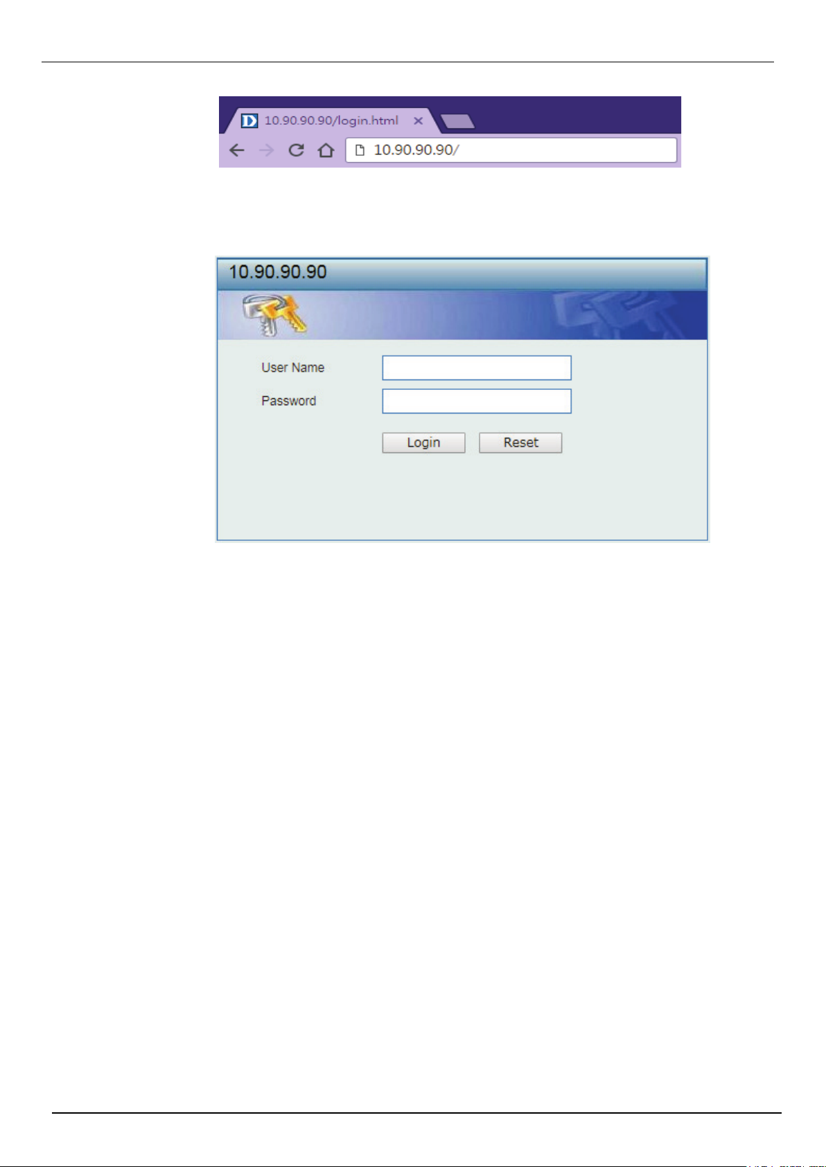
Figure 2-1 Displays entering the IP address in Internet Explorer
Figure 2-2 User Authentication window
This will open the user authentication window, as seen below.
Enter the User Name and Password in the corresponding fields and click Login. The default username
is admin and the default password is admin. This will open the Web-based user interface. The Switch’s
management features available in the web-based manager are explained below.
4
Page 12
Smart Wizard
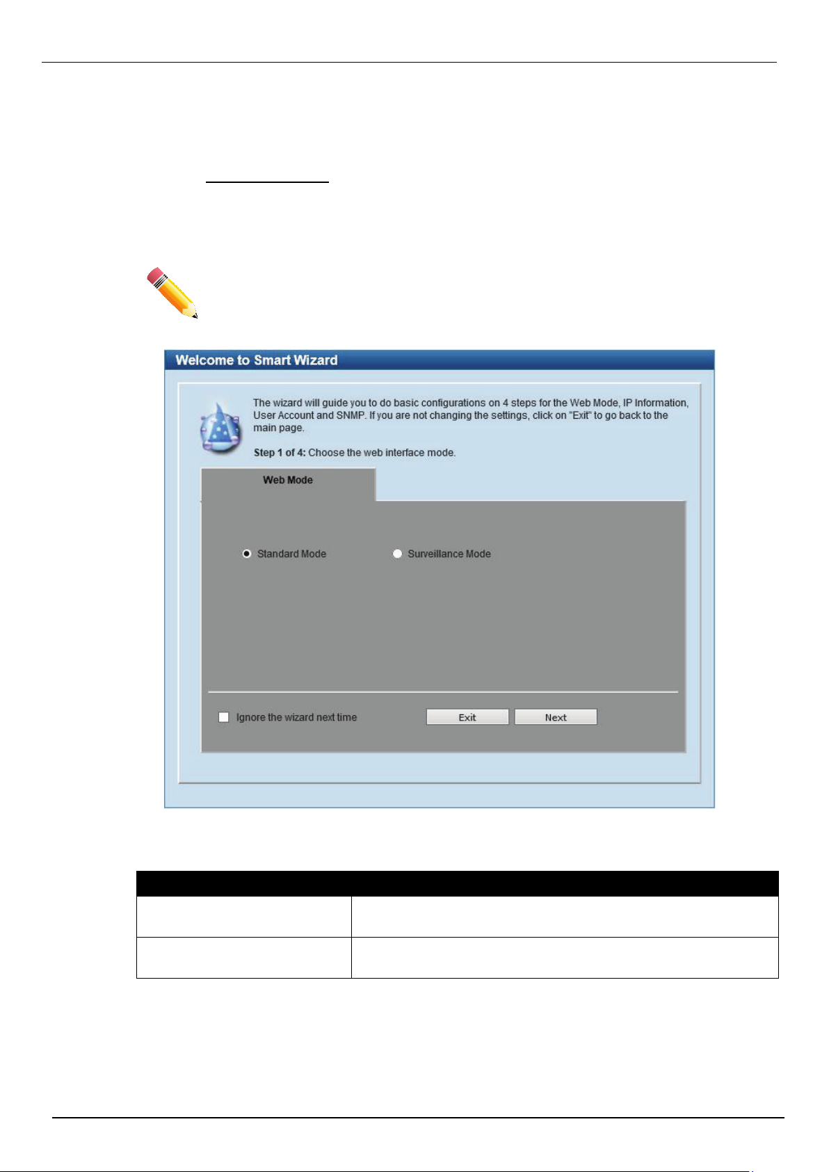
Figure 2-3 Web Mode
After a successfully connecting to the Web User Interface for the first time, the Smart Wizard embedded
Web utility will be launched. This wizard will guide the user through basic configuration steps that is
essential for first time connection to the Switch.
The Switch supports two Web Modes, Standard Mode and Surveillance Mode. The Standard Mode is
used to configure, manage, and monitor most of the software features on the Switch. The Surveillance
Mode is an additional web mode specifically designed to assist the user with surveillance features
supported by the Switch.
DIS-200G Series Industrial Gigabit Ethernet Smart Managed Switch
Step 1 - Web Mode
NOTE: The Web Mode can only be changed when one user session is connected to the
Web UI of the Switch.
The
fields that can be configured are described below:
Parameter Description
Standard Mode
Surveillance Mode
Tick the Ignore the wizard next time option to skip the Smart Wizard on the next login.
Click the Exit button to discard the changes made, exit the Smart Wizard, and continue to the Web UI.
Click the Next button to accept the changes made and continue to the next step.
Select this option to access the Standard Mode after the Smart
Wizard was completed.
Select this option to access the Surveillance Mode after the Smart
Wizard was completed.
5
Page 13
DIS-200G Series Industrial Gigabit Ethernet Smart Managed Switch
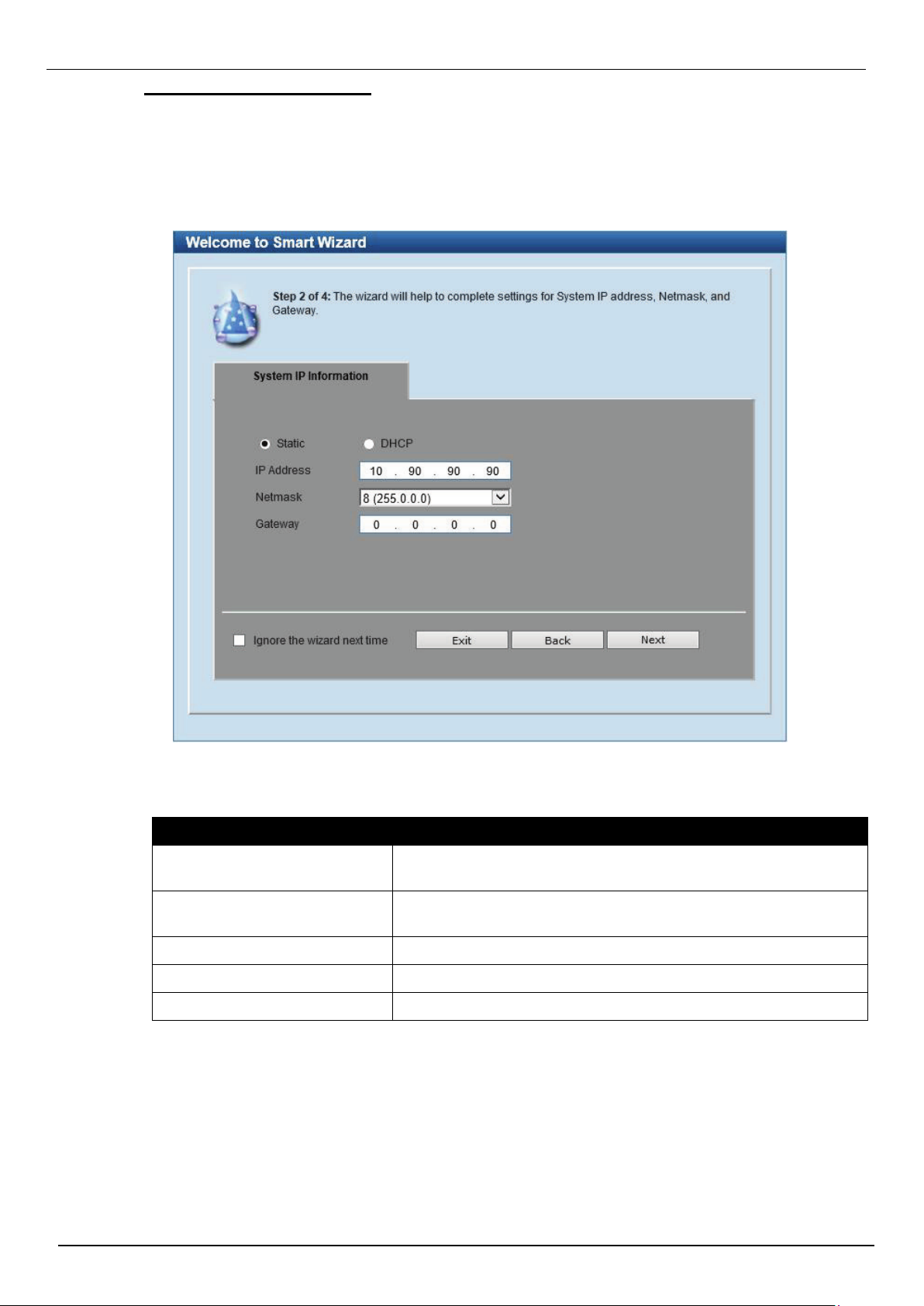
Figure 2-4 System IP Information window
Step 2 – System IP Information
In this window, the user can configure the IP address assignment method, the static IP address, Netmask
and Gateway address.
NOTE: The Switch will probe for surveillance devices every 30 seconds. If a surveillance device is not in
the same subnet as the switch, it will not be discovered automatically. Place the Switch management IP in
the same subnet as the surveillance devices for ONVIF cameras to be added to the Surveillance Mode
Web UI automatically.
The fields that can be configured are described below:
Parameter Description
Static
DHCP
IP Address
Netmask
Select this option to manually configure and use IP address
settings on this switch.
Select this option to obtain IP address settings from a DHCP
server.
Enter the IP address of the Switch here.
Select the Netmask option here.
Gateway
Tick the Ignore the wizard next time option to skip the Smart Wizard on the next login.
Click the Exit button to discard the changes made, exit the Smart Wizard, and continue to the Web UI.
Click the Next button to accept the changes made and continue to the next step.
Enter the default gateway IP address here.
6
Page 14
DIS-200G Series Industrial Gigabit Ethernet Smart Managed Switch
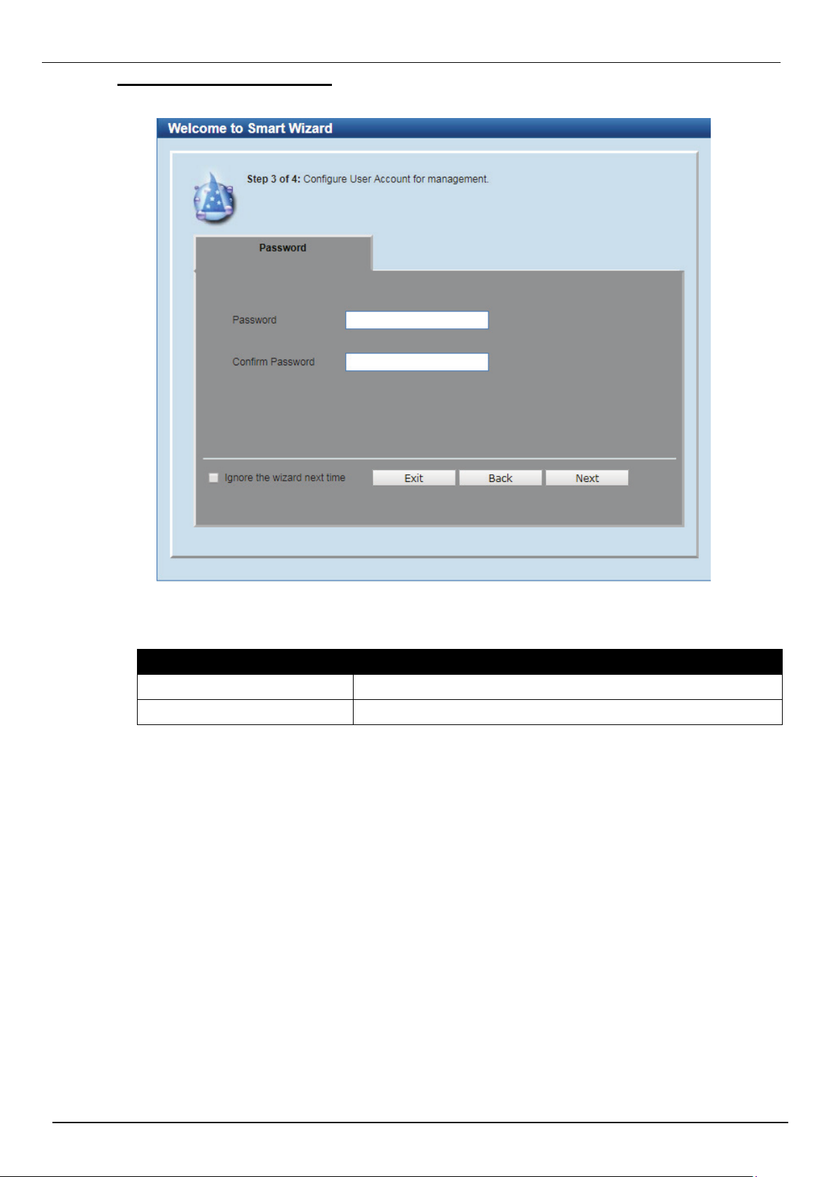
Figure 2-5 Password window
Step 3 – User Accounts Settings
In this window, the user can configure the user password of ‘admin’ account.
The fields that can be configured are described below:
Parameter Description
Password
Confirm Password
Tick the Ignore the wizard next time option to skip the Smart Wizard on the next login.
Click the Exit button to discard the changes made, exit the Smart Wizard, and continue to the Web UI.
Click the Back button to discard the changes made and return to the previous step.
Click the Next button to accept the changes made and continue to the next step.
Enter the new password for the user account here.
Enter the new password again for confirmation here.
7
Page 15
DIS-200G Series Industrial Gigabit Ethernet Smart Managed Switch
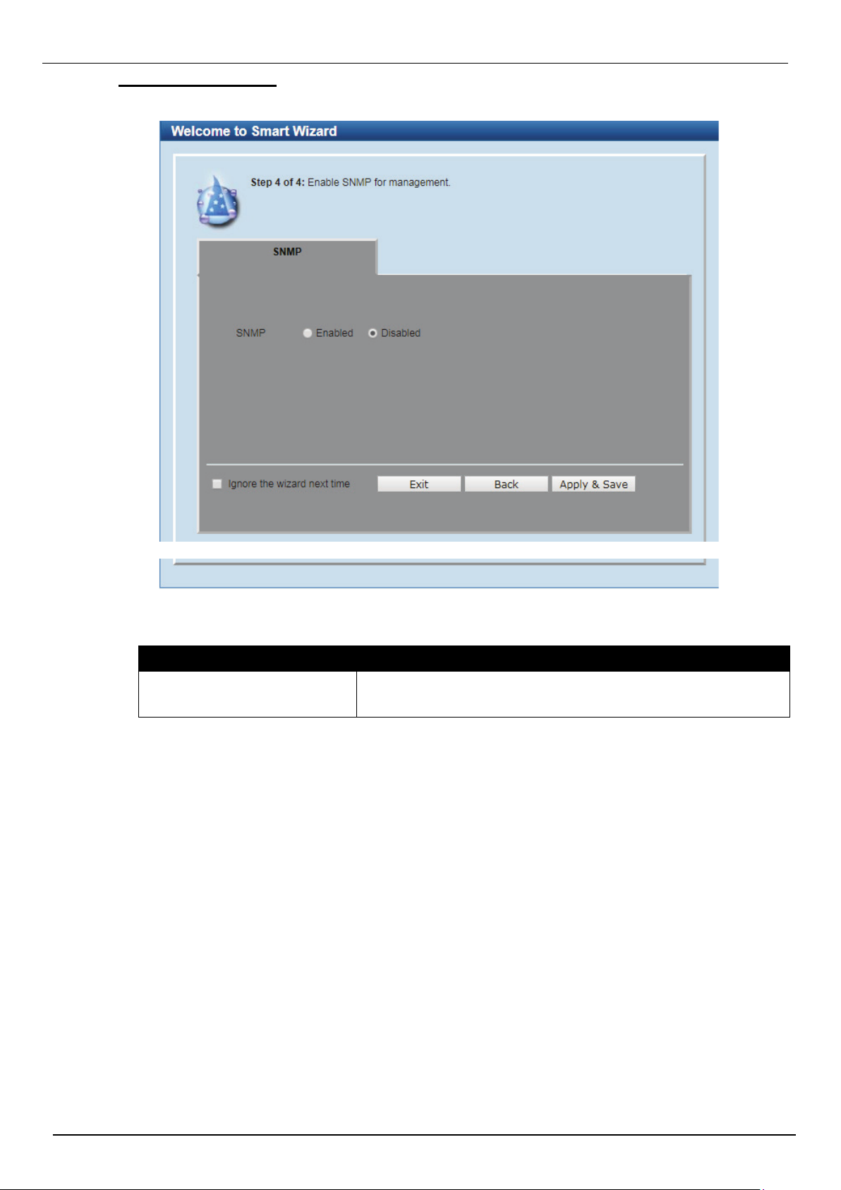
Figure 2-7 SNMP window
Figure 2-6 SNMP window
Step 4 – SNMP Settings
In this window, the user can enable or disable the SNMP function.
The fields that can be configured are described below:
Parameter Description
SNMP
Tick the Ignore the wizard next time option to skip the Smart Wizard on the next login.
Click the Exit button to discard the changes made, exit the Smart Wizard, and continue to the Web UI.
Click the Back button to discard the changes made and return to the previous step.
Click the Apply & Save button to accept the changes made and continue to the Web UI.
Select the Enabled option to enable the SNMP function.
Select the Disabled option to disable the SNMP function.
8
Page 16
DIS-200G Series Industrial Gigabit Ethernet Smart Managed Switch
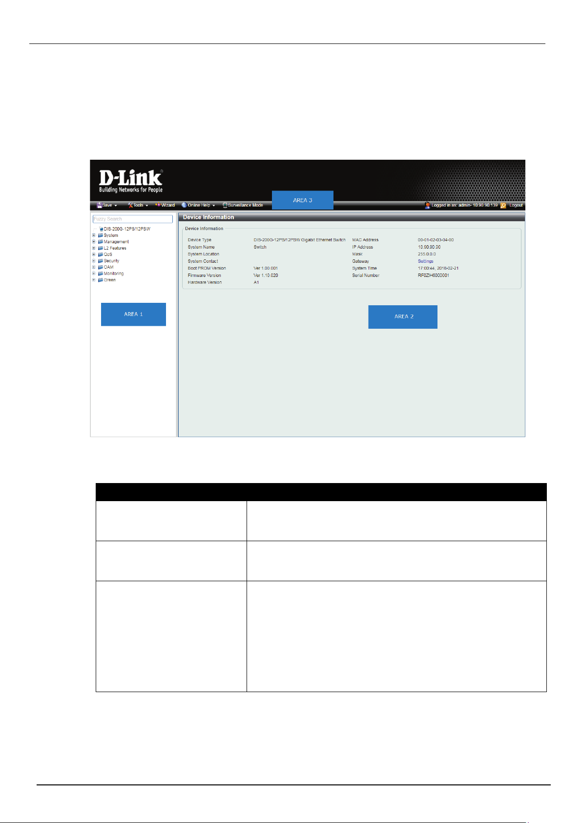
Figure 2-7 Web UI (Standard Mode)
Web User Interface (Web UI)
By clicking the Exit button in the Smart Wizard, you will enter the Web-based Management interface.
Areas of the User Interface
The figure below shows the Web UI in the Standard Mode. Three distinct areas that divide the user
interface, as described in the table.
The following Areas can be observed in the above window:
Parameter Description
AREA 1
AREA 2
AREA 3
Select the folder or window to display. Open folders and click the
hyperlinked window buttons and subfolders contained within them
to display windows.
Presents Switch status based on user selection and the entry of
configuration data. In addition, hyperlink of Settings is offered to
enable quick Gateway configuration.
Presents a toolbar used to access function like Save, Tools, the
Wizard and Online Help, accessing the Web UI in the Surveillance
Mode, and a Logout option.
Click the Surveillance Mode option to change the switch mode
from
Standard Mode to Surveillance Mode.
The user account and IP address currently logged into the Web UI
will also be displayed in this toolbar.
9
Page 17
Surveillance Mode
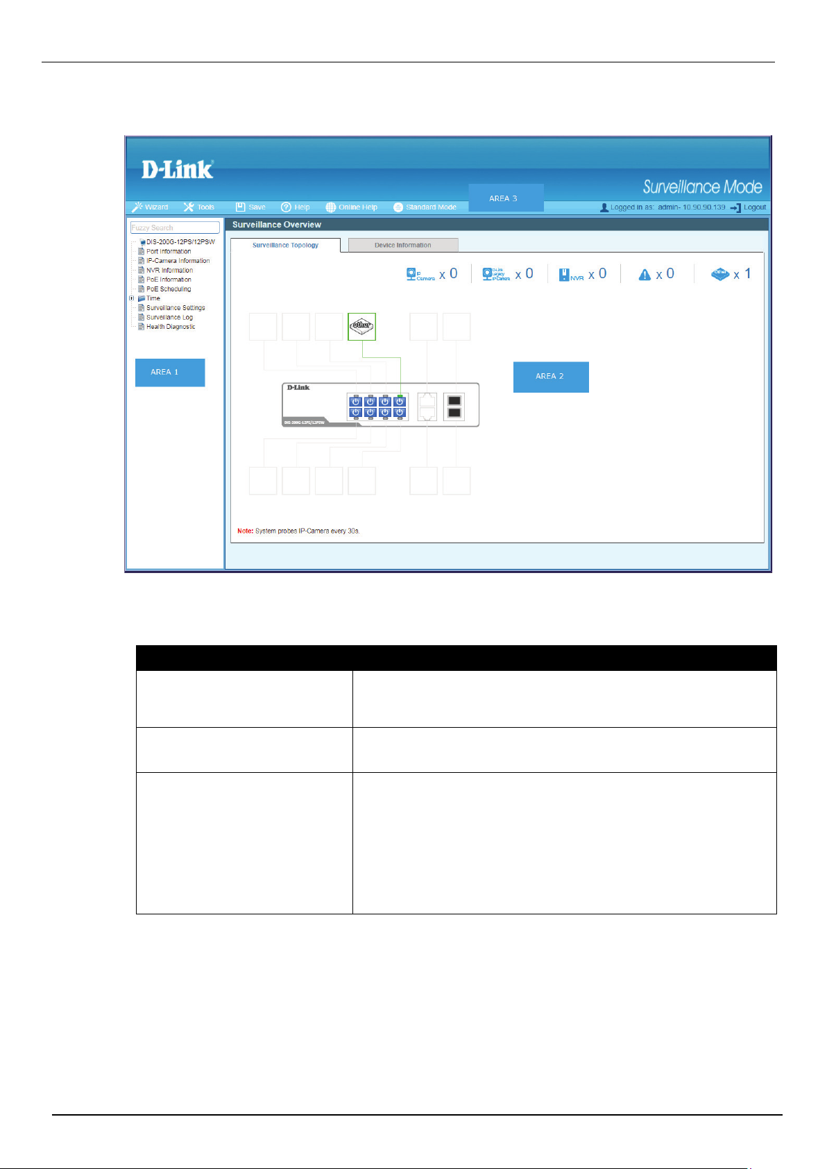
Figure 2-8 Web UI (Surveillance Mode)
After accessing the Web UI in the Surveillance Mode,the following will be displayed:.
DIS-200G Series Industrial Gigabit Ethernet Smart Managed Switch
The following Areas can be observed in the above window:
Parameter Description
AREA 1
AREA 2
AREA 3
Select the folder or window to display. Open folders and click the
hyperlinked window buttons and subfolders contained within them
to display windows.
In this area, configuration and monitoring window frames are
available based on the selections made in area 1.
Presents a toolbar used to access function like Save, Tools, the
Wizard and Online Help, accessing the Web
UI in the Surveillance Mode, and a Logout option.
Click the Standard Mode option to change the switch mode from
Surveillance Mode to Standard Mode.
The user account and IP address currently logged into the Web UI
will also be displayed in this toolbar.
10
Page 18
DIS-200G Series Industrial Gigabit Ethernet Smart Managed Switch
Figure 3-1 Save Configuration window
Figure 3-2 Firmware Information window
3. Save and Tools
Save Configuration
Firmware Information
Firmware Upgrade & Backup
Configuration Restore & Backup Log Backup
Ping
Reset
Reboot System
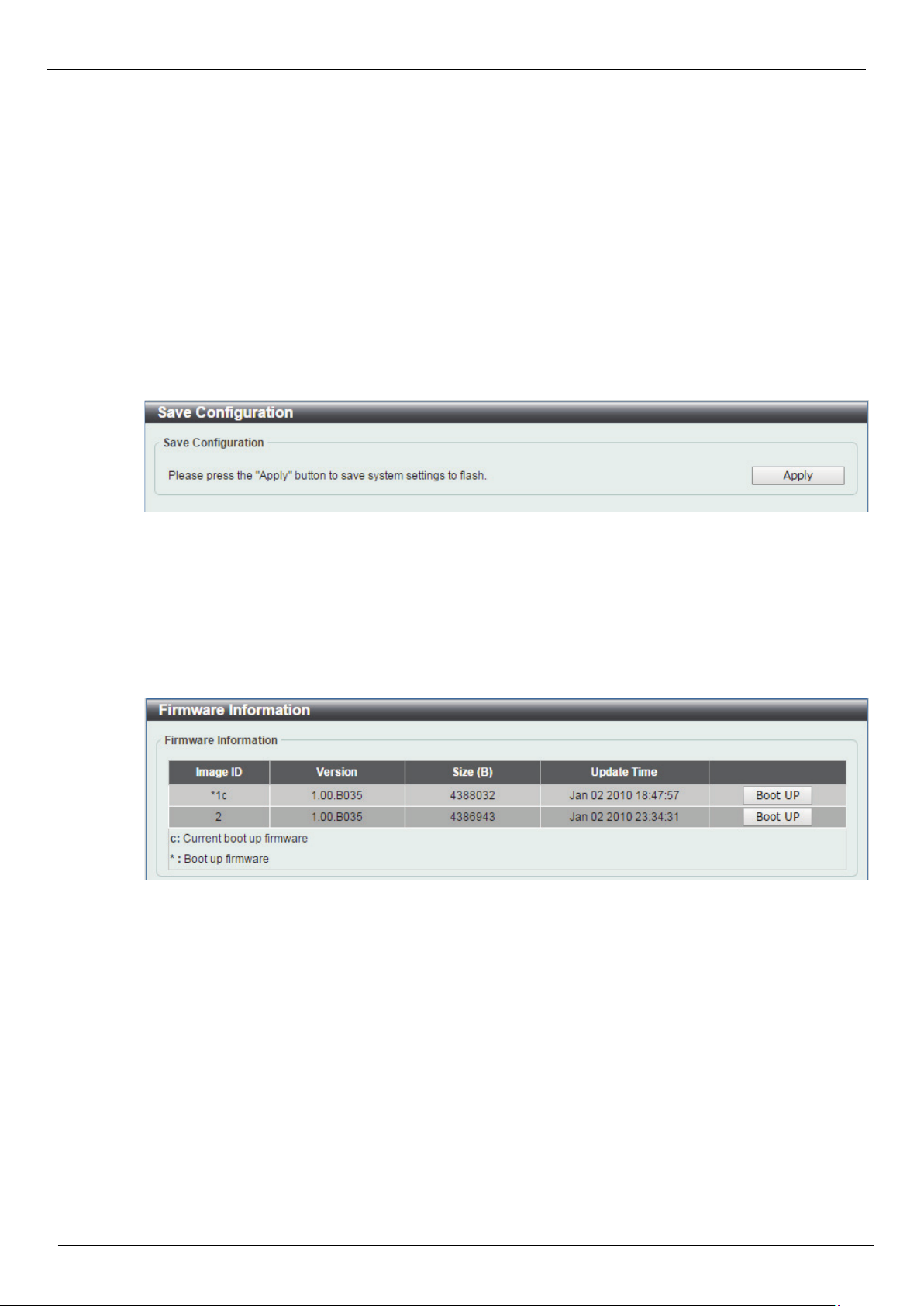
Save Configuration
This window is used to save the running configuration to the start-up configuration or the file system of
the Switch. This is to prevent the loss of configuration in the event of a power failure.
To view the following window, click Save > Save Configuration, as shown below:
Click the Apply button to save the configuration.
Firmware Information
This window is used to configure the firmware image boot up.
To view the following window, click Tools > Firmware Information, as shown below:
Click the Boot UP button of image 1 or image 2 for boot up.
11
Page 19
DIS-200G Series Industrial Gigabit Ethernet Smart Managed Switch
Figure 3-3 Firmware Upgrade from HTTP window
Figure 3-4 Firmware Upgrade from TFTP window
Firmware Upgrade & Backup
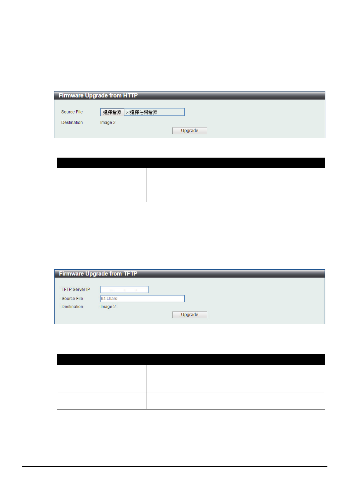
Firmware Upgrade from HTTP
This window is used to initiate a firmware upgrade from a local PC using HTTP.
To view the following window, click Tools > Firmware Upgrade & Backup > Firmware Upgrade from
HTTP, as shown below:
The fields that can be configured are described below:
Parameter Description
Source File
Destination
Click the Upgrade button to initiate the firmware upgrade.
Firmware Upgrade from TFTP
This window is used to initiate a firmware upgrade from a TFTP server.
To view the following window, click Tools > Firmware Upgrade & Backup > firmware Upgrade from
TFTP, as shown below:
The fields that can be configured are described below:
Click the Browse button to navigate to the location of the firmware
file located on the local PC.
The destination Image ID is automatically assigned to new
upgrade firmware by system.
Parameter Description
TFTP Server IP
Source File
Destination File
Click the Upgrade button to initiate the firmware upgrade.
Enter the TFTP server’s IPv4 address here.
Enter the source filename and path of the firmware file located on
the TFTP server here. This field can be up to 64 characters long.
The destination Image ID is automatically assigned to new
upgrade firmware by system.
12
Page 20
DIS-200G Series Industrial Gigabit Ethernet Smart Managed Switch
Figure 3-5 Firmware Backup to HTTP window
Figure 3-6 Firmware Backup to TFTP window
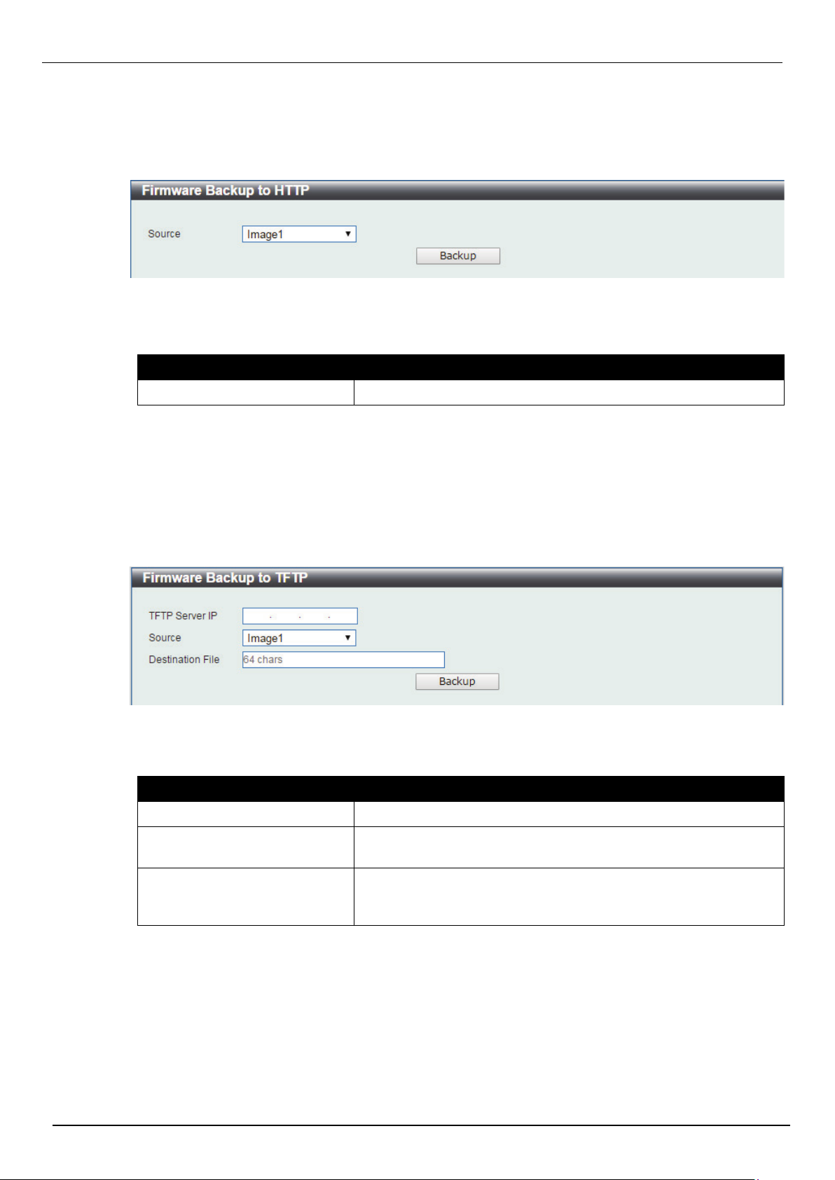
Firmware Backup to HTTP
This window is used to initiate a firmware backup to a local PC using HTTP.
To view the following window, click Tools > Firmware Upgrade & Backup > Firmware Backup to
HTTP, as shown below:
The fields that can be configured are described below:
Parameter Description
Source
Click the Backup button to initiate the firmware backup.
Firmware Backup to TFTP
This window is used to initiate a firmware backup to a TFTP server.
To view the following window, click Tools > Firmware Upgrade & Backup > Firmware Backup to TFTP,
as shown below:
The fields that can be configured are described below:
Parameter Description
Specify the firmware image ID to be backup.
TFTP Server IP
Source File
Destination File
Click the Backup button to initiate the firmware backup.
Enter the TFTP server’s IPv4 address here.
Enter the source filename and path of the firmware file located on
the Switch here. This field can be up to 64 characters long.
Enter the destination filename and path where the firmware should
be stored on the TFTP server. This field can be up to 64
characters long.
13
Page 21
DIS-200G Series Industrial Gigabit Ethernet Smart Managed Switch
Figure 3-8 Configuration Restore from TFTP window
Figure 3-7 Configuration Restore from HTTP window
Configuration Restore & Backup
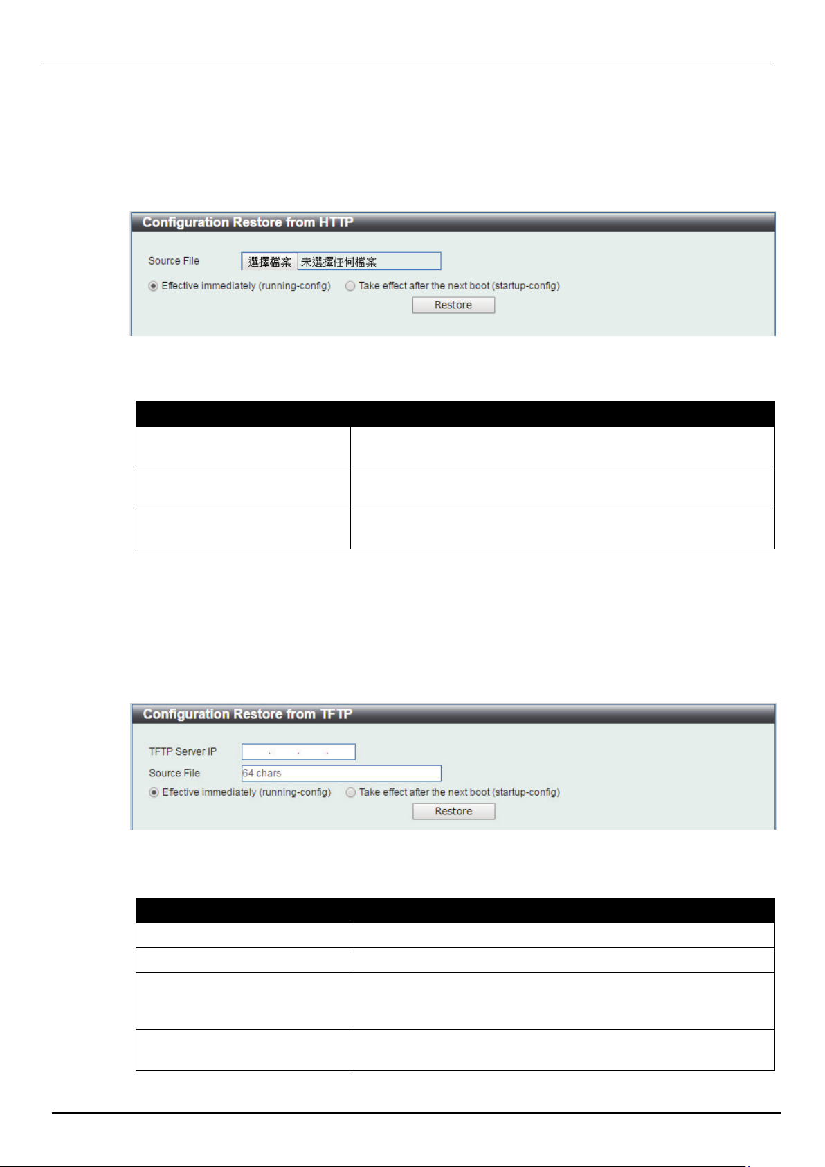
Configuration Restore from HTTP
This window is used to initiate a configuration restore from a local PC using HTTP.
To view the following window, click Tools > Configuration Restore & Backup > Configuration Restore
from HTTP, as shown below:
The fields that can be configured are described below:
Parameter Description
Source File
Effective
immediately(running-config)
Take effect after the next boot
(startup-config)
Click the Restore button to initiate the configuration restore.
Click the Browse button to navigate to the location of the
configuration file located on the local PC.
Specify this radio button to restore and overwrite the running
configuration file on the Switch.
Specify this radio button to restore and overwrite the start-up
configuration file on the Switch.
Configuration Restore from TFTP
This window is used to initiate a configuration restore from a TFTP server.
To view the following window, click Tools > Configuration Restore & Backup > Configuration Restore
from TFTP, as shown below:
The fields that can be configured are described below:
Parameter Description
Unit
TFTP Server IP
Source File
Effective immediately
(running-config)
Select the switch unit that will be used for this configuration here.
Enter the TFTP server’s IPv4 address here.
Enter the source filename and path of the configuration file located
on the TFTP server here. This field can be up to 64 characters
long.
Specify this radio button to restore and overwrite the running
configuration file on the Switch.
14
Page 22
DIS-200G Series Industrial Gigabit Ethernet Smart Managed Switch
Figure 3-9 Configuration Backup to HTTP window
Figure 3-10 Configuration Backup to TFTP window
Take effect after the next boot
(startup-config)
Click the Restore button to initiate the configuration restore.
Specify this radio button to restore and overwrite the start-up
configuration file on the Switch.
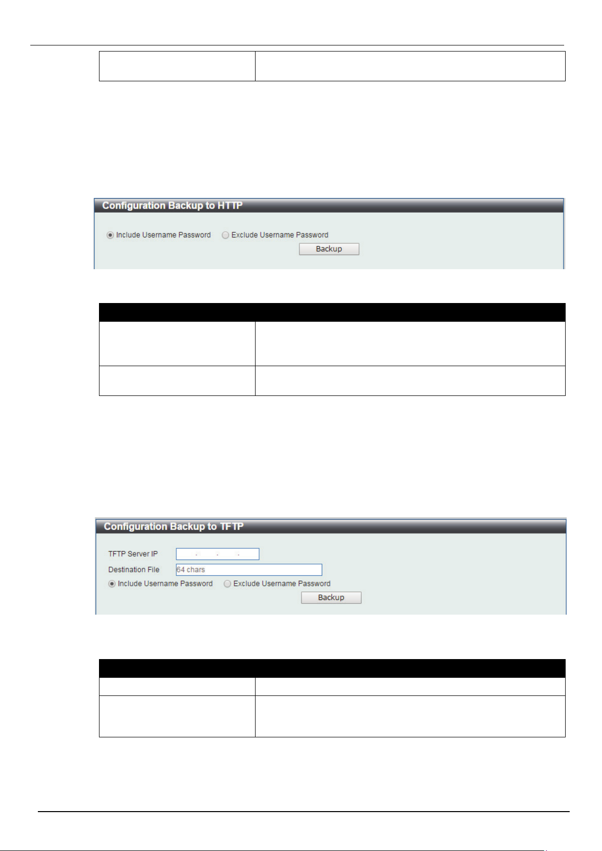
Configuration Backup to HTTP
This window is used to initiate a configuration file backup to a local PC using HTTP.
To view the following window, click Tools > Configuration Restore & Backup > Configuration Backup
to HTTP, as shown below:
The fields that can be configured are described below:
Parameter Description
Include Username Password
Specify this radio button to back up the running configuration file
include username password from the Switch.
Exclude Username Password
Click the Backup button to initiate the configuration file backup.
Specify this radio button to back up the running configuration file
exclude username password from the Switch.
Configuration Backup to TFTP
This window is used to initiate a configuration file backup to a TFTP server.
To view the following window, click Tools > Configuration Restore & Backup > Configuration Backup
to TFTP, as shown below:
The fields that can be configured are described below:
Parameter Description
TFTP Server IP
Destination File
Click the Backup button to initiate the configuration file backup.
Enter the TFTP server’s IPv4 address here.
Enter the destination filename and path where the configuration
file should be stored on the TFTP server. This field can be up to 64
characters long.
15
Page 23
DIS-200G Series Industrial Gigabit Ethernet Smart Managed Switch
Figure 3-11 Log Backup to HTTP window
Figure 3-12 Log Backup to TFTP window
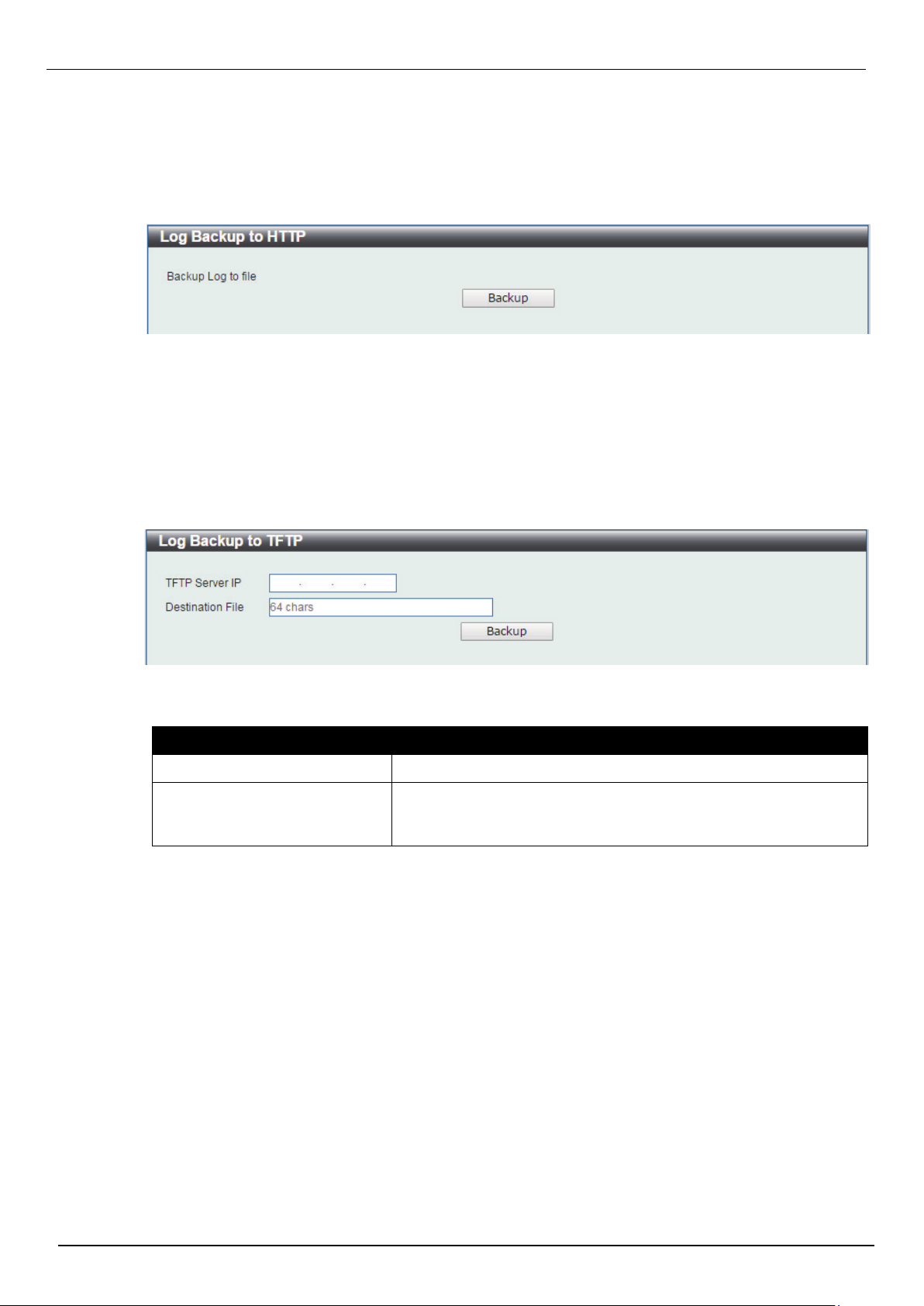
Log Backup
Log Backup to HTTP
This window is used to initiate a system log backup to a local PC using HTTP.
To view the following window, click Tools > Log Backup > Log Backup to HTTP, as shown below:
Click the Backup button to initiate the system log backup.
Log Backup to TFTP
This window is used to initiate a system log backup to a TFTP server.
To view the following window, click Tools > Log Backup > Log Backup to TFTP, as shown below:
TThe fields that can be configured are described below:
Parameter Description
TFTP Server IP
Destination File
Click the Backup button to initiate the system log backup.
Enter the TFTP server’s IPv4 address here.
Enter the destination filename and path where the log file should
be stored on the TFTP server. This field can be up to 64
characters long.
16
Page 24
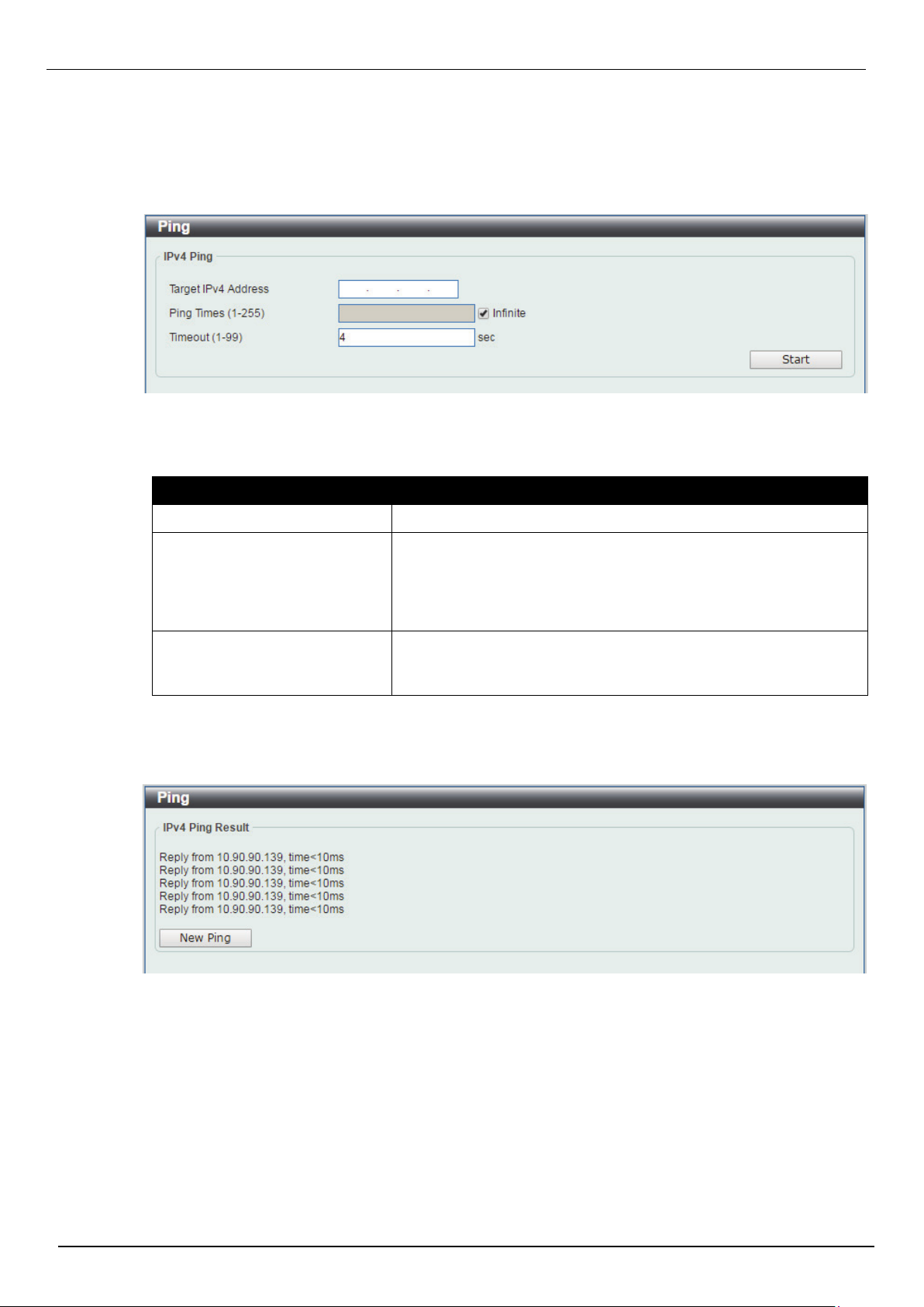
Ping
Figure 3-13 Ping window
Figure 3-14 Ping - IPv4 Ping Result window
DIS-200G Series Industrial Gigabit Ethernet Smart Managed Switch
Ping is a small program that sends ICMP Echo packets to the IP address you specify. The destination
node then responds to or “echoes” the packets sent from the Switch. This is very useful to verify
connectivity between the Switch and other nodes on the network.
To view the following window, click Tools > Ping, as shown below:
The fields that can be configured for IPv4 Ping are described below:
Parameter Description
Target IPv4 Address
Ping Times
Timeout
Click the Start button to initiate the Ping Test for each individual section.
After clicking the Start button in IPv4 Ping section, the following IPv4 Ping Result section will appear:
Select and enter an IP address to be pinged.
Enter the number of times desired to attempt to Ping the IPv4
address configured in this window. Users may enter a number of
times between 1 and 255. Tick the Infinite check box to keep
sending ICMP Echo packets to the specified IP address until the
program is stopped.
Select a timeout period between 1 and 99 seconds for this Ping
message to reach its destination. If the packet fails to find the IP
address in this specified time, the Ping packet will be dropped.
Click the New Ping button to halt the Ping Test and return to the IPv4 Ping section.
17
Page 25
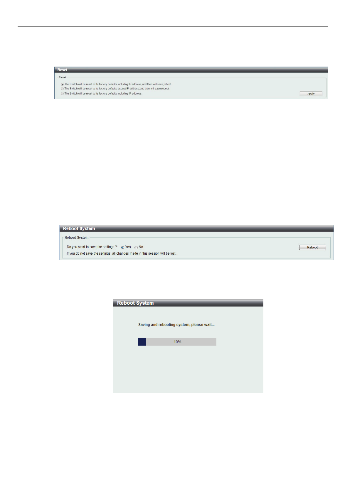
Reset
Figure 3-15 Reset window
Figure 3-16 Reboot System window
Figure 3-17 Reboot System - Rebooting window
DIS-200G Series Industrial Gigabit Ethernet Smart Managed Switch
This window is used to reset the Switch’s configuration to the factory default settings. To view the
following window, click Tools > Reset, as shown below:
Select the The Switch will be reset to its factory defaults including IP address, and then will save,
reboot option to reset the Switch’s configuration to its factory default settings.
Select the The Switch will be reset to its factory default except IP address, and then will save,
reboot option to reset the Switch’s configuration to its factory default settings. This option will exclude the
IP address from being changed.
Select the The Switch will be reset to its factory defaults including IP address option to reset the
Switch’s configuration to its factory default settings.
Click the Apply button to initiate the factory default reset and reboot the Switch.
Reboot System
This window is used to reboot the Switch and alternatively save the configuration before doing so. To
view the following window, click Tools > Reboot System, as shown below:
When rebooting the Switch, any configuration changes that was made during this session, will be lost
unless the Yes option is selected when asked to save the settings.
Click the Reboot button to alternatively save the settings and reboot the Switch.
18
Page 26
DIS-200G Series Industrial Gigabit Ethernet Smart Managed Switch
Figure 4-1 Device Information window
Figure 4-2 System Information Settings window
4. System
Device Information
System Information Settings Port Configuration
PoE
System Log Time
Time Profile
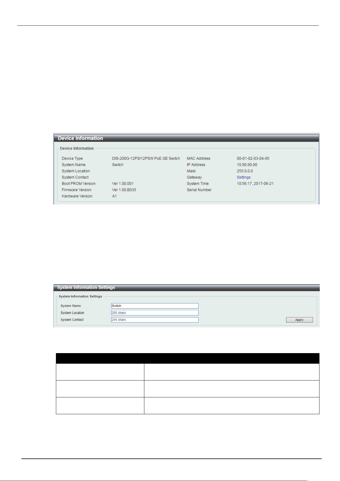
Device Information
In this window, the Device Information, CPU, and Used status are displayed. It appears automatically
when you log in the Switch. To return to the Device Information window after viewing other windows, click
the DIS-200G-12PS/12PSW link.
System Information Settings
System Information
The user can enter a System Name, System Location, and System Contact to aid in defining the Switch.
To view the following window, click System > System Information Settings, as shown below:
The fields that can be configured are described below:
Parameter Description
System Name
System Location
System Contact
Click the Apply button to accept the changes made.
Enter a system name for the Switch, if so desired. This name will
identify it in the Switch network.
Enter the location of the Switch, if so desired. This string can be up
to 255 characters long.
Enter a contact name for the Switch, if so desired. This string can
be up to 255 characters long.
19
Page 27
IPv4 Interface
Figure 4-3 IPv4 Interface window
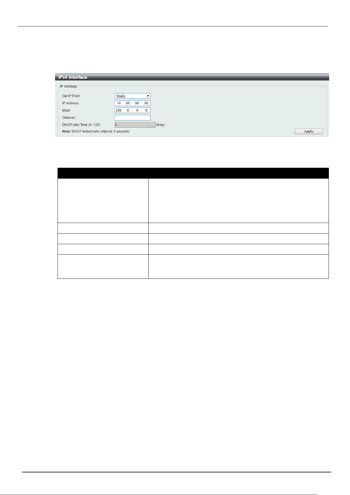
This window is used to view and configure the IPv4 interface settings.
To view the following window, click System > System Information Settings > IPv4 Interface, as shown
below:
The fields that can be configured are described below:
Parameter Description
DIS-200G Series Industrial Gigabit Ethernet Smart Managed Switch
Get IP From
IP Address
Mask
Gateway
DHCP Retry Time
Click the Apply button to accept the changes made.
Select the get IP from option here. Options to choose from are
Static and DHCP. When the Static option is selected, users can
enter the IPv4 address of this interface manually in the fields
provided. When the DHCP option is selected, this interface will
obtain IPv4 information automatically from the DHCP server
located on the local network.
Enter the IPv4 address for management interface here.
Enter the IPv4 subnet mask for management interface here.
Enter the IPv4 default gateway here.
Enter the DHCP retry times when “Get IP From” is selected as
DHCP mode. The times are valid from 5 to 120 times. Each time of
retry contains 5 seconds.
20
Page 28
IPv6 Interface
Figure 4-4 IPv6 Interface window
Figure 4-5 Port Settings window
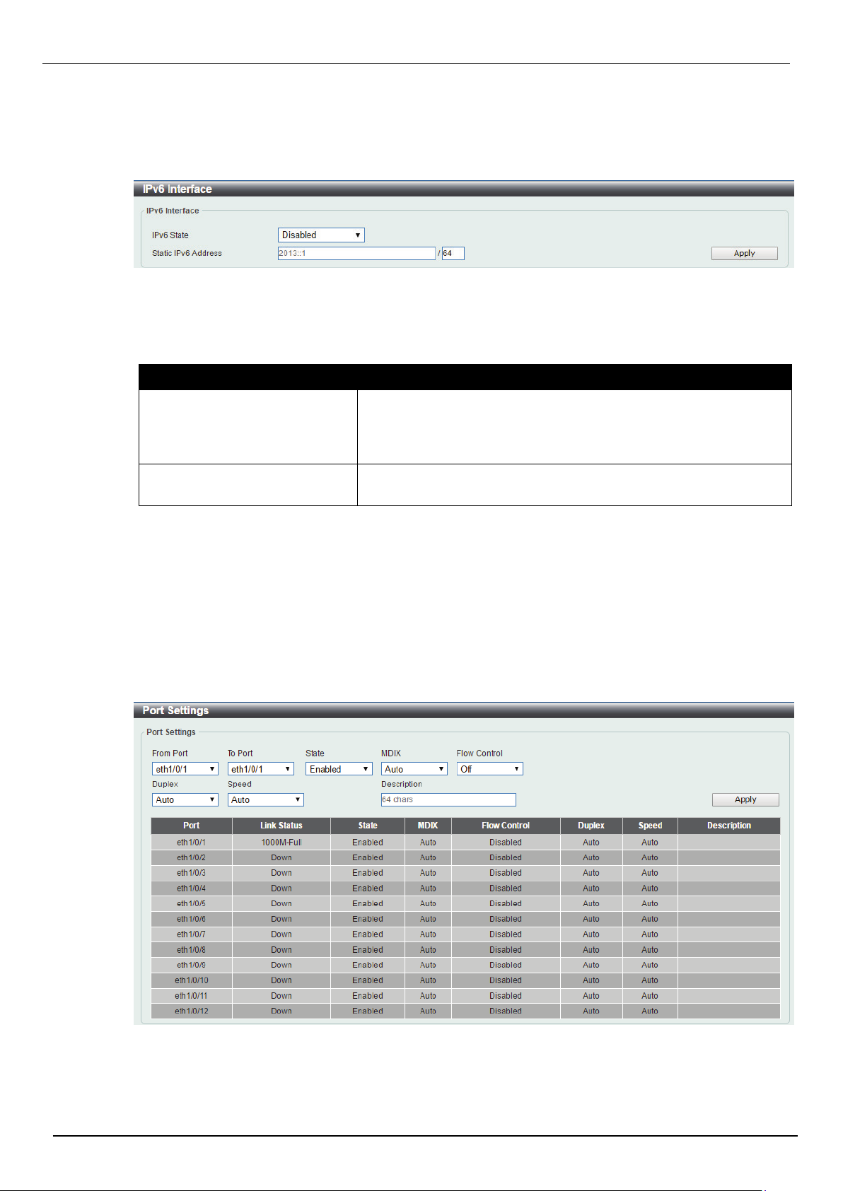
This window is used to view and configure the IPv6 interface settings.
To view the following window, click System > System Information Settings > IPv6 Interface, as shown
below:
The fields that can be configured are described below:
Parameter Description
DIS-200G Series Industrial Gigabit Ethernet Smart Managed Switch
IPv6 State
Static IPv6 Address / Mask
Click the Apply button to accept the changes made.
Port Configuration
Port Settings
This window is used to view and configure the Switch’s port settings.
To view the following window, click System > Port Configuration > Port Settings, as shown below:
Click to enable or disable the IPv6 feature. When state is enabled,
IPv6 link-local address will assigned to management VLAN
automatically. If state is disabled and static IPv6 address is not set,
the IPv6 feature will be disabled on switch.
Enter the IPv6 address and submask for management interface
here.
21
Page 29

DIS-200G Series Industrial Gigabit Ethernet Smart Managed Switch
Parameter Description
From Port / To Port
State
MDIX
Flow Control
Duplex
Speed
Select the appropriate port range used for the configuration here.
Select this option to enable or disable the physical port here.
Select the Medium Dependent Interface Crossover (MDIX) option
here. Options to choose from are Auto, Normal, and Cross.
Auto - Select this option for auto-sensing of the optimal type of
cabling.
Normal - Select this option for normal cabling. If this option is
selected, the port is in the MDIX mode and can be connected to a
PC’s NIC using a straight-through cable or a port (in the MDIX
mode) on another switch through a cross-over cable.
Cross - Select this option for cross cabling. If this option is
selected, the port is in the MDI mode and can be connected to a
port (in the MDIX mode) on another switch through a straight
cable.
Select to either turn flow control On or Off here. Ports configured
for full-duplex use 802.3x flow control, half-duplex ports use backpressure flow control, and Auto ports use an automatic selection of
the two.
Select the duplex mode used here. Options to choose from are
Auto, Half, and Full.
Select the port speed option here. This option will manually force
the connected on the selected port to only connect at the speed
specified here. Options to choose from are Auto, 10M, 100M,
1000M.
Description
Click the Apply button to accept the changes made.
Enter a 64 characters description for the corresponding port here.
22
Page 30
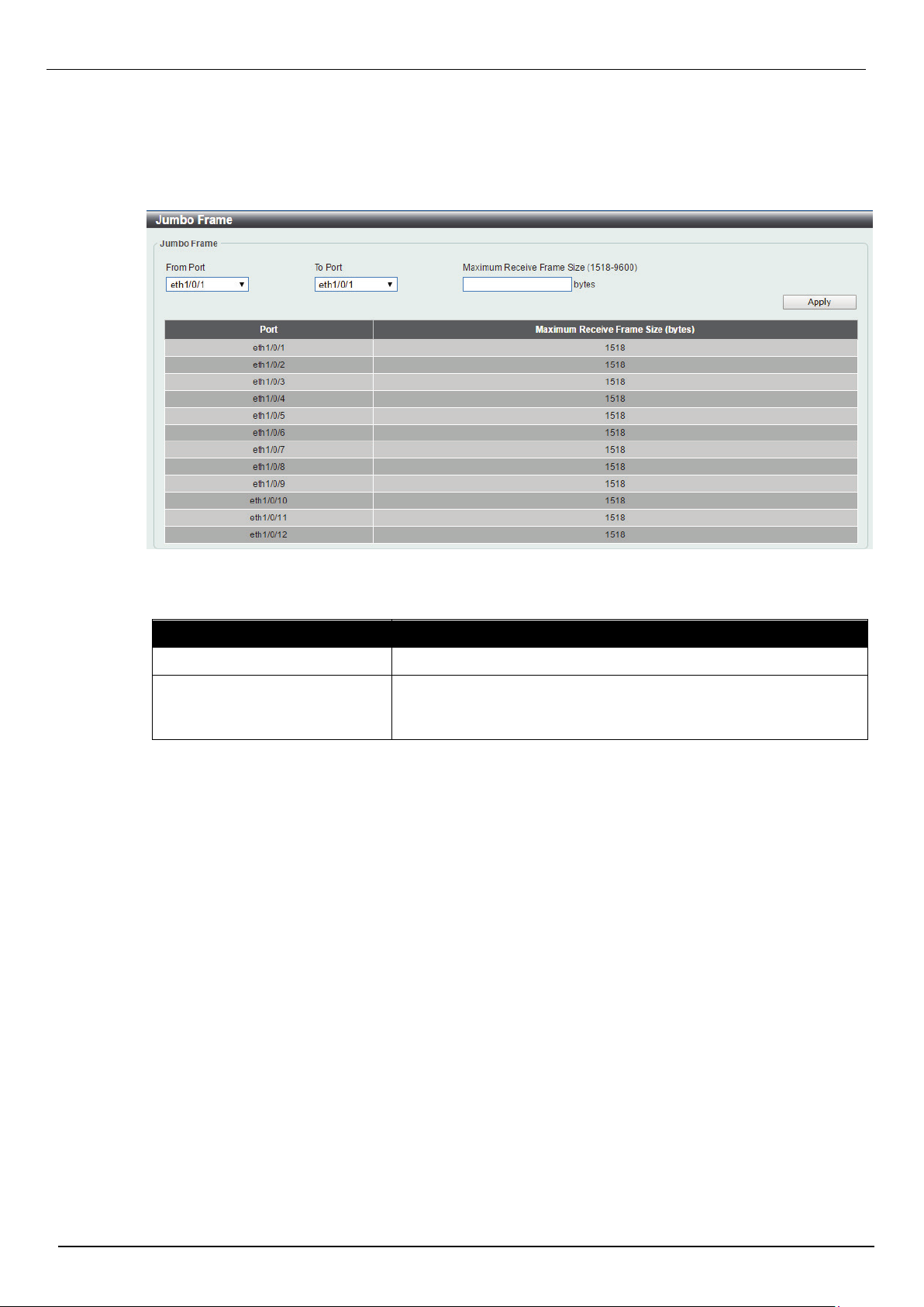
Jumbo Frame
Figure 4-6 Jumbo Frame window
This window is used to view and configure the Jumbo Frame size and settings. The Switch supports
jumbo frames. Jumbo frames are Ethernet frames with more than 1,518 bytes of payload. The Switch
supports jumbo frames with a maximum frame size of up to 9600 bytes.
To view the following window, click System > Port Configuration > Jumbo Frame, as shown below:
DIS-200G Series Industrial Gigabit Ethernet Smart Managed Switch
The fields that can be configured are described below:
Parameter Description
From Port / To Port
Maximum Receive Frame Size
Click the Apply button to accept the changes made.
Select the appropriate port range used for the configuration here.
Enter the maximum receive frame size value here. This value must
be between 1518 and 9600 bytes. By default, this value is 1518
bytes.
23
Page 31

DIS-200G Series Industrial Gigabit Ethernet Smart Managed Switch
Figure 4-7 PoE System window
PoE(DIS-200G-12PS and DIS-200G-12PSW Only)
This switch support Power over Ethernet (PoE) as defined by the IEEE 802.3af and 802.3at. All ports can
support PoE up to 30W. The Switch follows the standard PSE (Power Sourcing Equipment) pin-out
Alternative A, whereby power is sent out over pins 1, 2, 3 and 6. The Switches work with all D-Link
802.3af capable devices.
The Switch includes the following PoE features:
• Auto-discovery recognizes the connection of a PD (Powered Device) and automatically sends power
to it.
• The Auto-disable feature occurs under two conditions: firstly, if the total power consumption exceeds
the system power limit; and secondly, if the per port power consumption exceeds the per port power limit.
• Active circuit protection automatically disables the port if there is a short. Other ports will remain
active.
Based on 802.3af/at PDs receive power
according to the following classification:
Class Maximum power used by PD Class Maximum power used by PD
0 12.95W 0 15.4W
1 3.84W 1 4.0W
2 6.49W 2 7.0W
3 12.95W 3 15.4W
4 25.5W 4 30W
PoE System
This window is used to configure the PoE system, and display the detailed power information and PoE
chip parameters for PoE modules.
To view the following window, click System > PoE > PoE System, as shown below:
PSE provides power according to the following
classification:
The fields that can be configured are described below:
Parameter Description
Usage Threshold
Trap State
Click the Apply button to accept the changes made.
Enter the usage threshold to generate a log and send the
corresponding standard notification. The range is from 1 to 99
percent.
Select this option to enable or disable the sending of PoE
notifications.
24
Page 32

PoE Status
Figure 4-8 PoE Status window
Figure 4-9 PoE Configuration window
This window is used to configure the description, and display the PoE status of each port.
To view the following window, click System > PoE > PoE Status, as shown below:
DIS-200G Series Industrial Gigabit Ethernet Smart Managed Switch
PoE Configuration
This window is used to configure the PoE port.
To view the following window, click System > PoE > PoE Configuration, as shown below:
The fields that can be configured are described below:
Parameter Description
From Port / To Port
Priority
Mode
Select the appropriate port range used for the configuration here.
Select the priority for provisioning power to the port. Options to
choose from are Critical, High and Low.
Select the power management mode for the PoE ports. Options to
choose from are Auto and Never.
25
Page 33

DIS-200G Series Industrial Gigabit Ethernet Smart Managed Switch
Time Profile
Click the Delete Time Profile button to clear the setting in the corresponding Time Range field.
Click the Apply button to accept the changes made.
PD Alive
This window is used to configure the PD Alive function for PDs connected to the PoE ports. The ping
function is used to check if PDs, connected to the PoE ports, are active or not. When PDs appear to be
inactive, the specified action (Reset, Notify, or Both) will be taken.
View the following window, click System > PoE > PD Alive, as shown below:
Select the name of the time range to determine the activation
period.
Figure 4-10 PD Alive window
The fields that can be configured are described below:
Parameter Description
From Port / To Port
PD Alive State
PD IP Address
Poll Interval
Retry Count
Waiting Time
Action
Select the appropriate port range used for the configuration here.
Select to enable or disable the PD Alive function on the specified
port(s).
Enter the IP address of the PD here.
Enter the poll interval here. This is the interval between ping
messages from the system to PDs connected to the PoE port(s).
The range is from 10 to 300 seconds.
Enter the retry count here. This is the amount of ping messages
that will be sent (at each interval) when PDs are not responding.
The range is from 0 to 5.
Enter the waiting time here. This is how long the system will wait
before sending ping messages to the PD connected to the PoE
port after a 'Reset' action was taken. The range is from 30 to 300
seconds.
Select the action that will be taken here. Options to choose from
are Reset, Notify, and Both.
Reset - Specifies to reset the PoE port state (turn PoE off and on).
Notify - Specifies to send logs and traps to notify the administrator.
Both - Specifies to send logs and traps to notify the administrator
and to reset the PoE port state (turn PoE off and on).
Click the Apply button to accept the changes made.
26
Page 34

DIS-200G Series Industrial Gigabit Ethernet Smart Managed Switch
Figure 4-11 System Log Settings window
Figure 4-12 System Log Server Settings window
System Log
System Log Settings
This window is used to view and configure the system’s log settings.
To view the following window, click System > System Log > System Log Settings, as shown below:
The fields that can be configured for Global State are described below:
Parameter Description
System log
Click the Apply button to accept the changes made.
The fields that can be configured for Buffer Log Settings are described below:
Parameter Description
Buffer Log State
Click the Apply button to accept the changes made.
System Log Server Settings
This window is used to view and configure system log’s server settings.
To view the following window, click System > System Log > System Log Server Settings, as shown
below:
Select this option to enable or disable the global state.
Select whether the enable or disable the buffer log’s global state.
The fields that can be configured are described below:
Parameter Description
Host IPv4 Address
UDP Port
Enter the system log server’s IPv4 address here.
Enter the system log server’s UDP port number here. This value
must be 514 or between 1024 and 65535. By default, this value is
514.
27
Page 35

DIS-200G Series Industrial Gigabit Ethernet Smart Managed Switch
Figure 4-13 System Log window
Figure 4-14 Clock Settings window
Click the Apply button to accept the changes made.
System Log
This window is used to view and clear the system log.
To view the following window, click System > System Log > System Log, as shown below:
Severity
Facility
Select the severity value of the type of information that will be
logged. Options to choose from are Errors, Warning, Notice and
Informational.
Select the facility value here. Options to choose from are 0 to 7.
Click the Clear Log button to clear the system log entries displayed in the table.
Enter a page number and click the Go button to navigate to a specific page when multiple pages exist.
Time and SNTP
The Simple Network Time Protocol (SNTP) is a protocol for synchronizing computer clocks through the
Internet. It provides comprehensive mechanisms to access national time and frequency dissemination
services, organize the SNTP subnet of servers and clients, and adjust the system clock in each
participant.
Clock Settings
This window is used to configure the time settings for the Switch.
To view the following window, click System > Time > Clock Settings, as shown below:
The fields that can be configured are described below:
Parameter Description
Time (HH:MM:SS)
Date (DD / MM / YYYY)
Click the Apply button to accept the changes made.
Enter the current time in hours, minutes, and seconds.
Enter the current day, month, and year to update the system clock.
28
Page 36

Figure 4-15 Time Zone Settings window
Time Zone Settings
This window is used to configure time zones and Daylight Savings Time settings for SNTP.
To view the following window, click System > Time > Time Zone Settings, as shown below:
DIS-200G Series Industrial Gigabit Ethernet Smart Managed Switch
The fields that can be configured are described below:
Parameter Description
Summer Time State
Select the summer time setting. Options to choose from are
Disabled, Recurring Setting, and Date Setting.
Disabled - Select to disable the summer time setting.
Recurring Setting - Select to configure the summer time that
should start and end on the specified week day of the specified
month.
Date Setting - Select to configure the summer time that should
start and end on the specified date of the specified month.
Time Zone
Select to specify your local time zone’s offset from Coordinated
Universal Time (UTC).
The fields that can be configured for Recurring Setting are described below:
Parameter Description
From: Week of the Month
Select week of the month that summer time will start.
29
Page 37

DIS-200G Series Industrial Gigabit Ethernet Smart Managed Switch
Figure 4-16 SNTP Settings window
From: Day of the Week
From: Month
From: Time (HH:MM)
To: Week of the Month
To: Day of the Week
To: Month
To: Time (HH:MM)
Offset
Select the day of the week that summer time will start.
Select the month that summer time will start.
Select the time of the day that summer time will start.
Select week of the month that summer time will end.
Select the day of the week that summer time will end.
Select the month that summer time will end.
Select the time of the day that summer time will end.
Enter the number of minutes to add during summer time. The
default value is 60. The range of this offset is 30, 60, 90 and 120.
The fields that can be configured for Date Setting are described below:
Parameter Description
From: Date of the Month
From: Month
From: Year
From: Time (HH:MM)
To: Date of the Month
Select date of the month that summer time will start.
Select the month that summer time will start.
Enter the year that the summer time will start.
Select the time of the day that summer time will start.
Select date of the month that summer time will end.
To: Month
To: Year
To: Time (HH:MM)
Offset
Click the Apply button to accept the changes made.
SNTP Settings
This window is used to configure the time settings for the Switch.
To view the following window, click System > Time > SNTP Settings, as shown below:
Select the month that summer time will end.
Enter the year that the summer time will end.
Select the time of the day that summer time will end.
Enter the number of minutes to add during summer time. The
default value is 60. The range of this offset is 30, 60, 90 and 120.
The fields that can be configured for SNTP Global Settings are described below:
Parameter Description
SNTP State
Select this option to enable or disable SNTP.
30
Page 38

DIS-200G Series Industrial Gigabit Ethernet Smart Managed Switch
Figure 4-17 Time Range window
Poll Interval
Click the Apply button to accept the changes made.
The fields that can be configured for SNTP Server Setting are described below:
Parameter Description
IPv4 Address
Click the Apply button to accept the changes made.
Time Profile
This window is used to view and configure the time range settings.
To view the following window, click System > Time Profile, as shown below:
Enter the synchronizing interval in seconds. The value is from 30
to 99999 seconds. The default interval is 720 seconds.
Enter the IP address of the SNTP server which provides the clock
synchronization.
The fields that can be configured are described below:
Parameter Description
Range Name
From Week / To Week
From Time / To Time
Click the Apply button to accept the changes made.
Enter the name of the time range. This name can be up to 32
characters long.
Select the starting and ending days of the week that will be used
for this time range. Tick the Daily option to use this time range for
every day of the week. Tick the End Week Day option to use this
time range from the starting day of the week until the end of the
week, which is Sunday.
Select the starting and ending time of the day that will be used for
this time range. The first drop-down menu selects the hour and the
second drop-down menu selects the minute.
31
Page 39

DIS-200G Series Industrial Gigabit Ethernet Smart Managed Switch
Figure 5-1 User Management Settings window
5. Management
User Account Settings
Password Encryption
SNMP
RMON
HTTP/HTTPS
D-Link Discovery Protocol
User Account Settings
This window is used to create and configure the user accounts. The active user account sessions can be
viewed. The pre-defined user account privilege levels supported by this switch is:
Administrator - Privilege read-write. This administrator user account level can monitor all
system information and change any of the system configuration settings expressed in this
guide.
To view the following window, click Management > User Account Settings, as shown below:
The fields that can be configured are described below:
Parameter Description
User Name
Privilege
Password
Click the Apply button to accept the changes made.
Click the Delete button to delete the selected user.
Choose the user account name here.
Choose the privilege level of user.
The password belongs to the user account. Up to 32 characters.
32
Page 40

DIS-200G Series Industrial Gigabit Ethernet Smart Managed Switch
Figure 5-2 Password Encryption Settings window
Password Encryption
This window is used to configure the encryption of the password before stored in the configuration file.
To view the following window, click Management > Password Encryption, as shown below:
The fields that can be configured are described below:
Parameter Description
Password Encryption State
Password Type
Click the Apply button to accept the changes made.
Choose the enable or disable password encryption.
Choose the algorithm of password encryption when enabled.
33
Page 41

SNMP
Simple Network Management Protocol (SNMP) is an OSI Layer 7 (Application Layer) designed
specifically for managing and monitoring network devices. SNMP enables network management stations
to read and modify the settings of gateways, routers, switches, and other network devices. Use SNMP to
configure system features for proper operation, monitor performance and detect potential problems in the
Switch, switch group or network.
Managed devices that support SNMP include software (referred to as an agent), which runs locally on the
device. A defined set of variables (managed objects) is maintained by the SNMP agent and used to
manage the device. These objects are defined in a Management Information Base (MIB), which provides
a standard presentation of the information controlled by the on-board SNMP agent. SNMP defines both
the format of the MIB specifications and the protocol used to access this information over the network.
The Switch supports the SNMP versions 1, 2c, and 3. The three versions of SNMP vary in the level of
security provided between the management station and the network device.
In SNMP v.1 and v.2, user authentication is accomplished using ‘community strings’, which function like
passwords. The remote user SNMP application and the Switch SNMP must use the same community
string. SNMP packets from any station that has not been authenticated are ignored (dropped).
The default community strings for the Switch used for SNMP v.1 and v.2 management access are:
DIS-200G Series Industrial Gigabit Ethernet Smart Managed Switch
• public – Allows authorized management stations to retrieve MIB objects.
• private – Allows authorized management stations to retrieve and modify MIB objects.
SNMPv3 uses a more sophisticated authentication process that is separated into two parts. The first part
is to maintain a list of users and their attributes that are allowed to act as SNMP managers. The second
part describes what each user on that list can do as an SNMP manager.
The Switch allows groups of users to be listed and configured with a shared set of privileges. The SNMP
version may also be set for a listed group of SNMP managers. Thus, you may create a group of SNMP
managers that are allowed to view read-only information or receive traps using SNMPv1
while assigning a higher level of security to another group, granting read/write privileges using SNMPv3.
Using SNMPv3 individual users or groups of SNMP managers can be allowed to perform or be restricted
from performing specific SNMP management functions. The functions allowed or restricted are defined
using the Object Identifier (OID) associated with a specific MIB. An additional layer of security is available
for SNMPv3 in that SNMP messages may be encrypted. To read more about how to configure SNMPv3
settings for the Switch read the next section.
Traps
Traps are messages that alert network personnel of events that occur on the Switch. The events can be
as serious as a reboot (someone accidentally turned OFF the Switch), or less serious like a port status
change. The Switch generates traps and sends them to the trap recipient (or network manager). Typical
traps include trap messages for Authentication Failure, Topology Change and Broadcast\Multicast Storm.
MIBs
The Switch in the Management Information Base (MIB) stores management and counter information. The
Switch uses the standard MIB-II Management Information Base module. Consequently, values for MIB
objects can be retrieved from any SNMP-based network management software. In addition to the
standard MIB-II, the Switch also supports its own proprietary enterprise MIB as an extended Management
Information Base. Specifying the MIB Object Identifier may also retrieve the proprietary MIB. MIB values
can be either read-only or read-write.
34
Page 42

DIS-200G Series Industrial Gigabit Ethernet Smart Managed Switch
Figure 5-3 SNMP Global Settings window
The Switch incorporates a flexible SNMP management for the switching environment. SNMP
management can be customized to suit the needs of the networks and the preferences of the network
administrator. Use the SNMP V3 menus to select the SNMP version used for specific tasks.
The Switch supports the Simple Network Management Protocol (SNMP) versions 1, 2c, and 3. The
administrator can specify the SNMP version used to monitor and control the Switch. The three versions of
SNMP vary in the level of security provided between the management station and the network device.
SNMP settings are configured using the menus located on the SNMP V3 folder of the Web manager.
Workstations on the network that are allowed SNMP privileged access to the Switch can be restricted
with the Management Station IP Address menu.
SNMP Global Settings
This window is used to configure the SNMP global settings and trap settings.
To view the following window, click Management > SNMP > SNMP Global Settings, as shown below:
The fields that can be configured for SNMP Global Settings are described below:
Parameter Description
SNMP Global State
Select this option to enable or disable the SNMP feature.
The fields that can be configured for Trap Settings are described below:
Parameter Description
Trap Global State
SNMP Authentication Trap
Select this option to enable or disable the sending of all or specific
SNMP notifications.
Tick this option to control the sending of SNMP authentication
failure notifications. An authenticationFailuretrap is generated
when the device receives an SNMP message that is not properly
authenticated. The authentication method depends on the version
of SNMP being used. For SNMPv1 or SNMPv2c, authentication
failure occurs if packets are formed with an incorrect community
string
Port Link Up
Port Link Down
Tick this option to control the sending of port link up notifications. A
linkup trap is generated when the device recognizes that one of
the communication links has come up.
Tick this option to control the sending of port link down
notifications. A linkDown trap is generated when the device
recognizes a failure in one of the communication links.
35
Page 43

DIS-200G Series Industrial Gigabit Ethernet Smart Managed Switch
Coldstart
Warmstart
Click the Apply button to accept the changes made.
Tick this option to control the sending of SNMP coldStart
notifications.
Tick this option to control the sending of SNMP warmStart
notifications.
SNMP View Table Settings
This window is used to assign views to community strings that define which MIB objects can be accessed
by a remote SNMP manager. The SNMP Group created with this table maps SNMP users (identified in
the SNMP User Table) to the views created in the previous window.
To view the following window, click Management > SNMP > SNMP View Table Settings, as shown
below:
The fields that can be configured are described below:
Parameter Description
View Name
Subtree OID
View Type
Click the Add button to add a new entry based on the information entered.
Click the Delete button to remove the specified entry.
Figure 5-4 SNMP View Table Settings window
Type an alphanumeric string of up to 32 characters. This is used to
identify the new SNMP view being created.
Type the Object Identifier (OID) Subtree for the view. The OID
identifies an object tree (MIB tree) that will be included or excluded
from access by an SNMP manager.
Select the view type here. Options to choose from are Included,
and Excluded.
Included - Select to include this object in the list of objects that an
SNMP manager can access.
Excluded - Select to exclude this object from the list of objects that
an SNMP manager can access.
36
Page 44

DIS-200G Series Industrial Gigabit Ethernet Smart Managed Switch
Figure 5-5 SNMP Community Table Settings window
SNMP Community Table Settings
This window is used to create an SNMP community string to define the relationship between the SNMP
manager and an agent. The community string acts like a password to permit access to the agent on the
Switch. The characteristics can be associated with the community string:
Read/write or read-only level permission for the MIB objects accessible to the SNMP commun ity.
To view the following window, click Management > SNMP > SNMP Community Table Settings, as
shown below:
The fields that can be configured are described below:
Parameter Description
Community Name
View Name
Access Right
Enter an alphanumeric string of up to 32 characters that is used to
identify members of an SNMP community. This string is used like a
password to give remote SNMP managers access to MIB objects
in the Switch’s SNMP agent.
Enter an alphanumeric string of up to 32 characters that is used to
identify the group of MIB objects that a remote SNMP manager is
allowed to access on the Switch. The view name must exist in the
SNMP View Table.
Select the access right here. Options to choose from are Read
Only, and Read Write.
Read Only - SNMP community members using the community
string created can only read the contents of the MIBs on the
Switch.
Read Write - SNMP community members using the community
string created can read from, and write to the contents of the MIBs
on the Switch.
Click the Add button to add a new entry based on the information entered.
Click the Clear button to remove the specified entry.
37
Page 45

DIS-200G Series Industrial Gigabit Ethernet Smart Managed Switch
Figure 5-6 SNMP Group Table Settings window
SNMP Group Table Settings
An SNMP Group created with this table maps SNMP users (identified in the SNMP User Table) to the
views created in the previous window.
To view the following window, click Management > SNMP > SNMP Group Table Settings, as shown
below:
The fields that can be configured are described below:
Parameter Description
Group Name
User-based Security Model
Security Level
Enter the group name of a maximum of 32 characters. The syntax
is general string that does not allow space.
Select the security model here. Options to choose from are
SNMPv1, SNMPv2c, and SNMPv3.
SNMPv1 - Select to allow the group user to use the SNMPv1
security model.
SNMPv2c - Select to allow the group user to use the SNMPv2c
security model.
SNMPv3 - Select to allow the group user to use the SNMPv3
security model.
When selecting SNMPv3 in the User-based Security Model dropdown list, this option is available.
NoAuthNoPriv - Specify that there will be no authorization and no
encryption of packets sent between the Switch and a remote
SNMP manager.
AuthNoPriv - Specify that authorization will be required, but there
will be no encryption of packets sent between the Switch and a
remote SNMP manager.
AuthPriv - Specify that authorization will be required, and that
packets sent between the Switch and a remote SNMP manger will
be encrypted.
38
Page 46

DIS-200G Series Industrial Gigabit Ethernet Smart Managed Switch
Figure 5-8 SNMP User Table Settings window
Read View Name Enter the read view name that the group user can access.
Write View Name Enter the write view name that the group user can access.
Notify View Name Enter a write view name that the group user can access. The notify
view describes the object that can be reported its status via trap
packets to the group user.
Click the Add button to add a new entry based on the information entered.
Click the Delete button to remove the specified entry.
SNMP Engine ID Local Settings
The Engine ID is a unique identifier used for SNMP V3 implementations on the Switch.
To view the following window, click Management > SNMP > SNMP Engine ID Local Settings, as shown
below:
The fields that can be configured are described below:
Parameter Description
Engine ID
Click the Default button to revert the engine ID to the default.
Click the Apply button to accept the changes made.
SNMP User Table Settings
This window is used to configure and display the SNMP users that are currently configured on the Switch.
To view the following window, click Management > SNMP > SNMP User Table Settings, as shown
below:
Figure 5-7 SNMP Engine ID Local Settings window
Enter the engine ID string with the maximum of 24 characters.
39
Page 47

DIS-200G Series Industrial Gigabit Ethernet Smart Managed Switch
Figure 5-9 SNMP Host Table Settings
Parameter Description
User Name
Group Name
SNMP Version
SNMP V3 Encryption
Auth-Protocol
Priv-Protocol
Enter an alphanumeric string of up to 32 characters. This is used to
identify the SNMP users.
Enter the SNMP group name to which the user belongs. The syntax
is general string that does not allow spaces.
Select the SNMP version. Options to choose from are v1, v2c, and
v3.
When selecting v3 in the SNMP Version drop-down list, this option is
available. Options to choose from are None, Password, and
Key.
When selecting v3 in the SNMP Version drop-down list, and
selecting either Password or Key in the SNMP V3 Encryption dropdown list, this option is available. Select the authentication level.
Options to choose from are MD5, and SHA.
MD5 - Select to use the HMAC-MD5-96 authentication level. This
field will require the user to enter a password or a key.
SHA - Specify that the HMAC-SHA authentication protocol will be
used. This field will require the user to enter a password or a key.
When selecting v3 in the SNMP Version drop-down list, and
selecting either Password or Key in the SNMP V3 Encryption dropdown list, this option is available. Select the private protocol.
Options to choose from are None, and DES56.
None - Specify that no authorization protocol is in use.
DES56 - Specify that DES 56-bit encryption is in use, based on the
CBC-DES (DES-56) standard. This field will require the user to enter
a password or a key.
Click the Add button to add a new entry based on the information entered.
Click the Delete button to remove the specified entry.
SNMP Host Table Settings
This window is used to configure and display the recipient of the SNMP notification.
To view the following window, click Management > SNMP > SNMP Host Table Settings, as shown
below:
40
Page 48

DIS-200G Series Industrial Gigabit Ethernet Smart Managed Switch
The fields that can be configured are described below:
Parameter Description
Host IPv4 Address
SNMP Version
Security Level
UDP Port
Enter the IPv4 address of the SNMP notification host.
Select the security model here. Options to choose from are
SNMPv1, SNMPv2c, and SNMPv3.
SNMPv1 - Select to allow the group user to use the SNMPv1
security model.
SNMPv2c - Select to allow the group user to use the SNMPv2c
security model.
SNMPv3 - Select to allow the group user to use the SNMPv3
security model.
When selecting SNMPv3 in the User-based Security Model drop-
down list, this option is available.
NoAuthNoPriv - Specify that there will be no authorization and no
encryption of packets sent between the Switch and a remote
SNMP manager.
AuthNoPriv - Specify that authorization will be required, but there
will be no encryption of packets sent between the Switch and a
remote SNMP manager.
AuthPriv - Specify that authorization will be required, and that
packets sent between the Switch and a remote SNMP manger will
be encrypted.
Enter the UDP port number. The default trap UDP port number is
162. The range of UDP port numbers is from 0 to 65535. Some
port numbers may conflict with other protocols.
Community String / SNMPv3
User Name
Click the Add button to add a new entry based on the information entered.
Click the Delete button to remove the specified entry.
Enter the community string to be sent with the notification packet.
41
Page 49

DIS-200G Series Industrial Gigabit Ethernet Smart Managed Switch
RMON
RMON Global Settings
This window is used to enable or disable remote monitoring (RMON) for the rising and falling alarm trap
feature for the SNMP function on the Switch.
To view the following window, click Management > RMON > RMON Global Settings, as shown below:
The fields that can be configured are described below:
Parameter Description
RMON Rising Alarm Trap Select this option to enable or disable the RMON Rising Alarm
Figure 5-10 RMON Global Settings window
Trap Feature.
RMON Falling Alarm Trap Select this option to enable or disable the RMON Falling Alarm
Click the Apply button to accept the changes made.
RMON Statistics Settings
This window is used to configure and display the RMON statistics on the specified port.
To view the following window, click Management > RMON > RMON Statistics Settings, as shown
below:
The fields that can be configured are described below:
Trap Feature.
Figure 5-11 RMON Statistics Settings window
Parameter Description
Port
Index
Owner
Click the Add button to add a new entry based on the information entered.
Click the Delete button to remove the specified entry.
Click the Show Detail button to see the detail information of the specific port.
Enter a page number and click the Go button to navigate to a specific page when multiple pages exist.
Select to choose the port.
Enter the RMON table index. The value is from 1 to 65535
Enter the owner string. The string can be up to 127 characters.
42
Page 50

DIS-200G Series Industrial Gigabit Ethernet Smart Managed Switch
After clicking the Show Detail button, the following window will appear.
Click the Back button to return to the previous window.
RMON History Settings
This window is used to configure and display RMON MIB history statistics gathering on the specified port.
To view the following window, click Management > RMON > RMON History Settings, as shown below:
Figure 5-12 RMON Statistics Table window
Figure 5-13 RMON History Settings window
The fields that can be configured are described below:
Parameter Description
Port
Index
Bucket Number
Interval
Owner
Select to choose the port.
Enter the history group table index. The value is from 1 to 65535.
Enter Specifies the number of buckets specified for the RMON
collection history group of statistics. The range is from 1 to 65535.
The default value is 50.
Enter the time in seconds in each polling cycle. The range is from
1 to 3600.
Enter the owner string. The string can be up to 127 characters.
Click the Add button to add a new entry based on the information entered.
Click the Delete button to remove the specified entry.
Click the Show Detail button to see the detail information of the specific port.
Enter a page number and click the Go button to navigate to a specific page when multiple pages exist.
After clicking the Show Detail button, the following window will appear.
43
Page 51

DIS-200G Series Industrial Gigabit Ethernet Smart Managed Switch
Figure 5-15 RMON Alarm Settings window
Click the Back button to return to the previous window.
RMON Alarm Settings
This window is used to configure and display alarm entries to monitor an interface.
To view the following window, click Management > RMON > RMON Alarm Settings, as shown below:
Figure 5-14 RMON History Table window
The fields that can be configured are described below:
Parameter Description
Index
Interval
Variable
Type
Rising Threshold
Falling Threshold
Rising Event Number
Falling Event Number
Owner
Click the Add button to add a new entry based on the information entered.
Enter the alarm index. The range is from 1 to 65535.
Enter the interval in seconds for the sampling of the variable and
checking against the threshold. The valid range is from 1 to
2147483647 seconds.
Enter the object identifier of the variable to be sampled.
Select the monitoring type. Options to choose from are Absolute
and Delta.
Enter the rising threshold value between 0 and 2147483647.
Enter the falling threshold value between 0 and 2147483647.
Enter the index of the event entry that is used to notify the rising
threshold crossing event. The valid range is from 1 to 65535. If not
specified, no action is taken while crossing the ringing threshold.
Enter the index of the event entry that is used to notify the falling
threshold crossing event. The valid range is from 1 to 65535. If not
specified, no action is taken while crossing the falling threshold.
Enter the owner string up to 127 characters.
Click the Delete button to remove the specified entry.
Enter a page number and click the Go button to navigate to a specific page when multiple pages exist.
44
Page 52

DIS-200G Series Industrial Gigabit Ethernet Smart Managed Switch
RMON Event Settings
This window is used to configure and display event entries.
To view the following window, click Management > RMON > RMON Event Settings, as shown below:
The fields that can be configured are described below:
Figure 5-16 RMON Event Settings
Parameter Description
Index
Description
Type
Community
Owner
Click the Add button to add a new entry based on the information entered. \
Click the Delete button to remove the specified entry.
Click the View Logs button to see the detail information of the specific port.
Enter a page number and click the Go button to navigate to a specific page when multiple pages exist.
After clicking the View Logs button, the following window will appear.
Enter the index of the alarm entry between 1 and 65535.
Enter a description for the RMON event entry. The string is up to
127 characters long.
Select the RMON event entry type. Options to choose from are
None, Log, Trap, and Log and Trap.
Enter the community string. The string can be up to 127
characters.
Enter the owner string. The string can be up to 127 characters.
Click the Back button to return to the previous window.
Figure 5-17 Event Logs Table window
45
Page 53

HTTP/HTTPS
Figure 5-18 HTTP/HTTPS window
Figure 5-19 D-Link Discovery Protocol window
This window is used to configure the web server running on HTTP or HTTPS protocol.
To view the following window, click Management > HTTP/HTTPS, as shown below:
The fields that can be configured for HTTP/HTTPS are described below:
Parameter Description
DIS-200G Series Industrial Gigabit Ethernet Smart Managed Switch
WEB Session
Web Session Timeout
Click the Apply button to accept the changes made.
Select the protocol for web server.
Enter the session timeout value for web session. The range of this
value is from 60 to 36000 seconds.
D-Link Discovery Protocol
This window is used to configure and display D-Link Discovery Protocol (DDP).
To view the following window, click Management > D-Link Discovery Protocol, as shown below:
The fields that can be configured for D-Link Discovery Protocol are described below:
Parameter Description
D-Link Discovery Protocol
State
Report Timer
Click the Apply button to accept the changes made.
Select this option to enable or disable DDP global state.
Select the interval in seconds between two consecutive DDP
report messages. Options to choose from are 30, 60, 90,120, and
Never.
46
Page 54

DIS-200G Series Industrial Gigabit Ethernet Smart Managed Switch
Figure 6-1 Unicast Static FDB window
6. Layer 2 Features
FDB
VLAN
Spanning Tree
Loopback Detection
Link Aggregation
L2 Multicast Control
LLDP
FDB
Static FDB
Unicast Static FDB
This window is used to view and configure the static unicast forwarding settings on the Switch.
To view the following window, click L2 Features > FDB > Static FDB > Unicast Static FDB, as shown
below:
The fields that can be configured are described below:
Parameter Description
Port
VID
MAC Address
Click the Apply button to accept the changes made.
Click the Delete All button to delete all the entries found in the display table.
Click the Delete button to remove the specified entry.
Enter a page number and click the Go button to navigate to a specific page when multiple pages exist.
Allows the selection of the port number on which the MAC address
entered resides.
Enter the VLAN ID on which the associated unicast MAC address
resides.
Enter the MAC address to which packets will be statically
forwarded or dropped. This must be a unicast MAC address.
47
Page 55

DIS-200G Series Industrial Gigabit Ethernet Smart Managed Switch
Figure 6-2 Multicast Static FDB window
Figure 6-3 MAC Address Table Settings (Global Settings) window
Multicast Static FDB
This window is used to view and configure the multicast static FDB settings.
To view the following window, click L2 Features > FDB > Static FDB > Multicast Static FDB, as shown
below:
The fields that can be configured are described below:
Parameter Description
From Port / To Port
VID
MAC Address
Click the Apply button to accept the changes made.
Click the Delete All button to remove all the entries.
Click the Delete button to remove the specific entry.
Enter a page number and click the Go button to navigate to a specific page when multiple pages exist.
MAC Address Table Settings
This window is used to view and configure the MAC address table’s global settings.
To view the following window, click L2 Features > FDB > MAC Address Table Settings, as shown
below:
Select the appropriate port range used for the configuration here.
Enter the VLAN ID of the VLAN the corresponding MAC address
belongs to.
Enter the static destination MAC address of the multicast packets.
This must be a multicast MAC address. The format of the
destination MAC address is 01-XX-XX-XX-XX-XX.
The fields that can be configured are described below:
Parameter Description
Aging Time
Click the Apply button to accept the changes made.
After clicking the MAC Address Learning tab, at the top of the page, the following page will be available.
Enter the MAC address table’s aging time value here. This value
must be between 10 and 1000000 seconds. Entering 0 will disable
MAC address aging. By default, this value is 300 seconds.
48
Page 56

DIS-200G Series Industrial Gigabit Ethernet Smart Managed Switch
Figure 6-4 MAC Address Table Settings (MAC Address Learning) window
Figure 6-5 MAC Address Table window
The fields that can be configured are described below:
Parameter Description
From Port / To Port
State
Click the Apply button to accept the changes made.
MAC Address Table
This window is used to view the entries listed in the MAC address table.
To view the following window, click L2 Features > FDB > MAC Address Table, as shown below:
Select the range of ports that will be used for this configuration
here.
Select to enable or disable the MAC address learning function on
the ports specified here.
Click the Clear All button to clear all dynamic MAC addresses.
49
Page 57

DIS-200G Series Industrial Gigabit Ethernet Smart Managed Switch
Figure 6-7 VLAN Configuration Wizard (Create VLAN) Window
Figure 6-6 VLAN Configuration Wizard (Select VLAN) window
VLAN
VLAN Configuration Wizard
This window is used to guide the user to create a new VLAN or configure an existing VLAN on the
Switch.
Step 1 – Select VLAN
To view the following window, click L2 Features > VLAN > VLAN Configuration Wizard, as shown
below:
The fields that can be configured are described below:
Parameter Description
Create VLAN VID
Configure VLAN VID
Click the Next button to continue to the next step.
Select and enter a new VLAN ID.
Select and enter an existing VLAN ID.
Step 2 – Create/Configure VLAN
After clicking the Next button, the following window will appear.
50
Page 58

DIS-200G Series Industrial Gigabit Ethernet Smart Managed Switch
Figure 6-9 Allowed VLAN Window
Figure 6-8 VLAN Configuration Wizard (Configure VLAN) Window
The fields that can be configured are described below:
Parameter Description
VLAN Name
Tagged
Untagged
Not Member
Native VLAN (PVID)
Click the View Allowed VLAN button to see the allowed VLAN information for all ports.
Click the Back button to return to the previous step.
Click the Apply button to accept the changed made.
After clicking the View Allowed VLAN button, the following window will appear.
Enter the name of the VLAN.
Click to designate the post as tagged. Click the All button to select
all ports.
Click to designate the port as untagged. Click the All button to
select all ports
Click to allow an individual port to be specified as a non-VLAN
member. Click the All button to select all ports.
Click to designate the port as native VLAN. Click the All button to
select all ports.
51
Page 59

802.1Q VLAN
Figure 6-10 802.1Q VLAN window
Figure 6-11 Management VLAN window
This window is used to view and configure the VLAN settings on this switch.
To view the following window, click L2 Features > VLAN > 802.1Q VLAN, as shown below:
The fields that can be configured for 802.1Q VLAN are described below:
Parameter Description
DIS-200G Series Industrial Gigabit Ethernet Smart Managed Switch
VID List
Click the Apply button to accept the changes made.
Click the Delete button to remove the specific entry.
Click the Edit button to re-configure the specific entry.
Enter a page number and click the Go button to navigate to a specific page when multiple pages exist.
Management VLAN
This window is used to configure the management VLAN function.
To view the following window, click L2 Features > VLAN > Management VLAN, as shown below:
The fields that can be configured are described below:
Enter the VLAN ID list that will be created here.
Parameter Description
VID
Click the Apply button to accept the changes made.
Enter the VID to allow user use this VLAN to manage the switch.
52
Page 60

GVRP
Figure 6-12 GVRP Global window
GVRP Global
This window is used to view and configure the GARP VLAN Registration Protocol (GVRP) global settings.
To view the following window, click L2 Features > VLAN > GVRP > GVRP Global, as shown below:
The fields that can be configured are described below:
DIS-200G Series Industrial Gigabit Ethernet Smart Managed Switch
Parameter Description
Asymmetric VLAN State
Dynamic VLAN Creation
Join Time
Leave Time
Leave All Time
Click the Apply button to accept the changes made.
Select this option to enable or disable the global GVRP state here.
Select this option to enable or disable the dynamic VLAN creation
function here.
Enter the Join Time value in centiseconds. This value must be
between 1 and 20 centiseconds. By default, this value is 20
centiseconds.
Enter the Leave Time value in centiseconds. This value must be
between 60 and 300 centiseconds. By default, this value is 60
centiseconds.
Enter the Leave All Time value in centiseconds. This value must
be between 1000 and 5000 centiseconds. By default, this value is
1000 centiseconds.
GVRP Port
This window is used to view and configure the GVRP port settings.
To view the following window, click L2 Features > VLAN > GVRP > GVRP Port, as shown below:
53
Page 61

DIS-200G Series Industrial Gigabit Ethernet Smart Managed Switch
Replace. When selecting All, all the advertised VLANs will be
Figure 6-14 GVRP Advertise VLAN window
Figure 6-13 GVRP Port window
Guide The fields that can be configured are described below:
Parameter Description
From Port / To Port
GVRP Status
Click the Apply button to accept the changes made.
Select the appropriate port range used for the configuration here.
Select this option to enable or disable the GVRP port status. This
enables the port to dynamically become a member of a VLAN. By
default, this option is disabled.
GVRP Advertise VLAN
This window is used to view and configure the GVRP advertised VLAN settings.
To view the following window, click L2 Features > VLAN > GVRP > GVRP Advertise VLAN, as shown
below:
The fields that can be configured are described below:
Parameter Description
From Port / To Port
Action
Select the appropriate port range used for the configuration here.
Select the advertised VLAN to port mapping action that will be
taken here. Options to choose from are All, Add, Remove and
54
Page 62

DIS-200G Series Industrial Gigabit Ethernet Smart Managed Switch
used.
Figure 6-15 GVRP Forbidden VLAN window
Advertise VID List
Click the Apply button to accept the changes made.
Enter the advertised VLAN ID list here.
GVRP Forbidden VLAN
This window is used to view and configure the GVRP forbidden VLAN settings.
To view the following window, click L2 Features > VLAN > GVRP > GVRP Forbidden VLAN, as shown
below:
The fields that can be configured are described below:
Parameter Description
From Port / To Port
Action
Forbidden VID List
Click the Apply button to accept the changes made.
Select the appropriate port range used for the configuration here.
Select the forbidden VLAN to port mapping action that will be
taken here. Options to choose from are All, Add, Remove and
Replace. When selecting All, all the forbidden VLANs will be used.
Enter the forbidden VLAN ID list here.
55
Page 63

Asymmetric VLAN
Figure 6-16 Asymmetric VLAN window
Figure 6-17 VLAN Interface window
Figure 6-18 VLAN Interface Information window
This window is used to configure the asymmetric VLAN function.
To view the following window, click L2 Features > VLAN > Asymmetric VLAN, as shown below:
The fields that can be configured are described below:
Parameter Description
DIS-200G Series Industrial Gigabit Ethernet Smart Managed Switch
Asymmetric VLAN State
Click the Apply button to accept the changes made.
VLAN Interface
This window is used to view and configure VLAN interface settings.
To view the following window, click L2 Features > VLAN > VLAN Interface, as shown below:
Select this option to enable or disable the asymmetric VLAN
function
Click the View Detail button to view more detailed information about the VLAN on the specific interface.
Click the Edit button to re-configure the specific entry.
After clicking the VLAN Detail button, the following page will appear.
56
Page 64

DIS-200G Series Industrial Gigabit Ethernet Smart Managed Switch
Figure 6-19 Configure VLAN Interface - Access window
Figure 6-20 Configure VLAN Interface - Hybrid window
More detailed information about the VLAN of the specific interface is displayed.
Click the Back button to return to the previous window.
After click the Edit button, the following window will appear. This is a dynamic window that will change
when a different VLAN Mode was selected. When Access was selected as the VLAN Mode, the
following page will appear.
TThe fields that can be configured are described below:
Parameter Description
VLAN Mode
Acceptable Frame
Ingress Checking
VID
Clone
From Port / To Port
Click the Apply button to accept the changes made.
Click the Back button to return to the previous window.
When Hybrid was selected as the VLAN Mode, the following page will appear.
Select the VLAN mode option here. Options to choose from are
Access, Hybrid, and Trunk.
Select the acceptable frame behavior option here. Options to
choose from are Tagged Only, Untagged Only, and Admit All.
Select this option to enable or disable the ingress checking
function.
Enter the VLAN ID used for this configuration here. This value
must be between 1 and 4094.
Tick this option to apply the configuration to the specified ports.
Select the appropriate port range used for the configuration here.
57
Page 65

DIS-200G Series Industrial Gigabit Ethernet Smart Managed Switch
available. Enter the VLAN ID used for this configuration here. This
Figure 6-21 Configure VLAN Interface - Trunk window
The fields that can be configured are described below:
Parameter Description
VLAN Mode
Acceptable Frame
Ingress Checking
Native VLAN
VID
Action
Add Mode
Allowed VLAN Range
Click the Apply button to accept the changes made.
Click the Back button to return to the previous window.
When Trunk was selected as the VLAN Mode, the following page will appear.
Select the VLAN mode option here. Options to choose from are
Access, Hybrid, and Trunk.
Select the acceptable frame behavior option here. Options to
choose from are Tagged Only, Untagged Only, and Admit All.
Select the check box to enable or disable the ingress checking
function.
Tick this option to enable the native VLAN function.
After ticking the Native VLAN check box, this option will be
available. Enter the VLAN ID used for this configuration here. This
value must be between 1 and 4094.
Select the action that will be taken here. Options to choose from
are
Add, Remove, Tagged, and Untagged.
Select whether to add an Untagged or Tagged parameters.
Enter the allowed VLAN range information here.
The fields that can be configured are described below:
Parameter Description
VLAN Mode
Acceptable Frame
Ingress Checking
Select the VLAN mode option here. Options to choose from are
Access, Hybrid, and Trunk.
Select the acceptable frame behavior option here. Options to
choose from are Tagged Only, Untagged Only, and Admit All.
After selecting Trunk as the VLAN Mode the following parameter
will be available. Select to enable or disable the ingress checking
function.
Native VLAN
VID
Tick the check box to enable the native VLAN function. Also select
if this VLAN supports Untagged or Tagged frames.
After ticking the Native VLAN check box, this option will be
58
Page 66

DIS-200G Series Industrial Gigabit Ethernet Smart Managed Switch
value must be between 1 and 4094.
Action
Allowed VLAN Range
Click the Apply button to accept the changes made.
Click the Back button to return to the previous window.
Select the action that will be taken here. Options to choose from
are
All, Add, Remove, and Except.
Enter the allowed VLAN range information here.
59
Page 67

DIS-200G Series Industrial Gigabit Ethernet Smart Managed Switch
Figure 6-22 Auto Surveillance Properties window
Auto Surveillance VLAN
Auto Surveillance Properties
This window is used to configure the auto surveillance VLAN global settings and display the ports
surveillance VLAN information.
To view the following window, click L2 Features > VLAN > Auto Surveillance VLAN > Auto
Surveillance Properties, as shown below:
The fields that can be configured for Global Settings are described below:
Parameter Description
Surveillance VLAN State
Surveillance VLAN ID
Surveillance VLAN CoS
Aging Time
ONVIF Discover Port
Select this option to enable or disable the surveillance VLAN state.
Enter the surveillance VLAN ID. The range is from 2 to 4094.
Select the priority of the surveillance VLAN from 0 to 7.
Enter the aging time of surveillance VLAN. The range is from 1 to
65535 minutes. The default value is 720 minutes. The aging time
is used to remove a port from surveillance VLAN if the port is an
automatic surveillance VLAN member. When the last surveillance
device stops sending traffic and the MAC address of this
surveillance device is aged out, the surveillance VLAN aging timer
will be started. The port will be removed from the surveillance
VLAN after expiration of surveillance VLAN aging timer. If the
surveillance traffic resumes during the aging time, the aging timer
will be reset and stop.
Enter the TCP/UDP port number here. The range is either 554, or
from 1025 to 65535. This is used to configure the TCP/UDP port
number for RTSP stream snooping. ONVIF-capable IPC and
ONVIF-capable NVR utilize WS-Discovery to find other devices.
Once IPCs are discovered, the Switch can further discover NVRs
by snooping RTSP, HTTP, and HTTPS packets between NVRs
and IPCs. These packets cannot be snooped if the TCP/UDP port
is not equal to the RTSP port number.
60
Page 68

DIS-200G Series Industrial Gigabit Ethernet Smart Managed Switch
Figure 6-23 User -defined MAC Settings window
Log State
Click the Apply button to accept the changes made.
The fields that can be configured for Port Settings are described below:
Parameter Description
From Port / To Port
State
Click the Apply button to accept the changes made.
Set the Surveillance VLAN log state
Select the appropriate port range used for the configuration here.
Select this option to enable or disable the state of the port.
MAC Settings and Surveillance Device
This window is used to configure the user-defined surveillance device OUI and display the surveillance
VLAN information.
To view the following window, click L2 Features > VLAN > Auto Surveillance VLAN > MAC Settings
and Surveillance Device, as shown below:
The fields that can be configured are described below:
Parameter Description
Component Type
Description
MAC Address
Mask
Click the Apply button to accept the changes made.
Click the Delete button to remove the specified entry.
After clicking the Auto Surveillance VLAN Summary tab, the following page will appear.
Select the surveillance component type. Options to choose from
are Video Management Server, VMS Client/Remote Viewer, Video
Encoder, Network Storage, and Other IP Surveillance Device.
Enter the description for the user-defined OUI with a maximum of
32 characters.
Enter the OUI MAC address.
Enter the OUI MAC address matching bitmask.
61
Page 69

DIS-200G Series Industrial Gigabit Ethernet Smart Managed Switch
Figure 6-24 Auto Surveillance VLAN Summary window
Figure 6-25 ONVIF IP-Camera Information window
Figure 6-26 ONVIF IP-Camera Information (More Detail) window
Figure 6-27 ONVIF IP-Camera Information (Edit) window
ONVIF IP-Camera Information
This window is used to display ONVIF IP camera information.
To view the following window, click L2 Features > VLAN > Auto Surveillance VLAN > ONVIF IP-
Camera Information, as shown below:
Click the IP Address hyperlink to connect to the Web Interface of the IP camera.
Click the More Detail button to view more detailed ONVIF IP camera information.
Click the Edit button to configure the state and description of the IP camera.
After click the More Detail button, the following window will appear.
Guide After click the Edit button, the following window will appear.
The fields that can be configured are described below:
Parameter Description
IP-Camera State
Description
Select to enable or disable the IP camera state here.
Enter the description for this IP camera here.
62
Page 70

DIS-200G Series Industrial Gigabit Ethernet Smart Managed Switch
Figure 6-28 ONVIF NVR Information window
Figure 6-29 ONVIF NVR Information (IP-Camera List) window
Figure 6-30 ONVIF NVR Information (Edit) window
Click the Back button to discard the changes made and return to the previous window.
Click the Apply button to accept the changes made.
ONVIF NVR Information
This window is used to display ONVIF Network Video Recorder (NVR) information.
To view the following window, click L2 Features > VLAN > Auto Surveillance VLAN > ONVIF NVR
Information, as shown below:
Click the IP Address hyperlink to connect to the Web Interface of the NVR.
Click the IP-Camera List button to view the list of IP cameras that are connected to the NVR.
Click the Edit button to configure the description of the NVR.
Guide After click the IP-Camera List button, the following window will appear.
Click the IP Address hyperlink to connect to the Web Interface of the IP camera.
Click the Back button to return to the previous window.
After click the Edit button, the following window will appear.
The additional fields that can be configured are described below:
Parameter Description
Description
Click the Apply button to accept the changes made.
Enter the description for this NVR here.
63
Page 71

Voice VLAN
Figure 6-31 Voice VLAN Global window
Voice VLAN Global
Voice VLAN is a VLAN used to carry voice traffic from IP phone. Because the sound quality of an IP
phone call will be deteriorated if the data is unevenly sent, the quality of service (QoS) for voice traffic
shall be configured to ensure the transmission priority of voice packet is higher than normal traffic.
The switches determine whether a received packet is a voice packet by checking its source MAC
address. If the source MAC addresses of packets comply with the organizationally unique identifier (OUI)
addresses configured by the system, the packets are determined as voice packets and transmitted in
voice VLAN.
To view the following window, click L2 Features > VLAN > Voice VLAN > Voice VLAN Global, as show
below:
DIS-200G Series Industrial Gigabit Ethernet Smart Managed Switch
The fields that can be configured are described below:
Parameter Description
Voice VLAN State
Voice VLAN ID
Voice VLAN CoS
Aging Time
Click the Apply button to accept the changes made for each individual section.
Select this option to enable or disable the voice VLAN.
Enter the voice VLAN ID. The value is range from 2 to 4094.
Select the priority of the voice VLAN from 0 to 7.
Enter the aging time of surveillance VLAN. The range is from 1 to
65535 minutes. The default value is 720 minutes. The aging time
is used to remove a port from voice VLAN if the port is an
automatic VLAN member. When the last voice device stops
sending traffic and the MAC address of this voice device is aged
out, the voice VLAN aging timer will be started. The port will be
removed from the voice VLAN after expiration of voice VLAN aging
timer. If the voice traffic resumes during the aging time, the aging
timer will be reset and stop.
Voice VLAN Port
This window is used to show the ports voice VLAN information.
To view the following window, click L2 Features > VLAN > Voice VLAN > Voice VLAN Port, as show
below:
64
Page 72

DIS-200G Series Industrial Gigabit Ethernet Smart Managed Switch
Figure 6-32 Voice VLAN Port window
The fields that can be configured are described below:
Parameter Description
From Port / To Port
State
Mode
Click the Apply button to accept the changes made.
Select the appropriate port range used for the configuration here.
Select this option to enable or disable the state of the port.
Select the mode of the port. Options to choose from are Auto
Untagged, Auto Tagged, and Manual.
65
Page 73

DIS-200G Series Industrial Gigabit Ethernet Smart Managed Switch
Figure 6-33 Voice VLAN OUI window
Figure 6-34 Voice VLAN Device window
Voice VLAN OUI
This window is used to configure the user-defined voice traffic’s OUI. The OUI is used to identify the voice
traffic. There are a number of pre-defined OUIs. The user can further define the user-defined OUIs if
needed. The user-defined OUI cannot be the same as the pre-defined OUI.
To view the following window, click L2 Features > VLAN > Voice VLAN > Voice VLAN OUI, as show
below:
The fields that can be configured are described below:
Parameter Description
OUI Address
Mask
Description
Click the Apply button to accept the changes made.
Click the Delete button to remove the specified entry.
Enter the OUI MAC address.
Enter the OUI MAC address matching bitmask.
Enter the description for the user-defined OUI with a maximum of
32 characters.
Voice VLAN Device
This window is used to show voice devices that are connected to the ports. The start time is the time
when the device is detected on this port, the activate time is the latest time saw the device sending the
traffic.
To view the following window, click L2 Features > VLAN > Voice VLAN > Voice VLAN Device, as show
below:
66
Page 74

DIS-200G Series Industrial Gigabit Ethernet Smart Managed Switch
Spanning Tree
This Switch supports three versions of the Spanning Tree Protocol: 802.1D-1998 STP, 802.1D-2004
Rapid STP, and 802.1Q- 2005 MSTP. 802.1D-1998 STP will be familiar to most networking professionals.
However, since 802.1D-2004 RSTP and 802.1Q-2005 MSTP have been recently introduced to D -Link
managed Ethernet switches, a brief introduction to the technology is provided below followed by a
description of how to set up 802.1D-1998 STP, 802.1D-2004 RSTP, and 802.1Q-2005 MSTP.
802.1Q-2005 MSTP
Multiple Spanning Tree Protocol, or MSTP, is a standard defined by the IEEE community that allows
multiple VLANs to be mapped to a single spanning tree instance, which will provide multiple pathways
across the network. Therefore, these MSTP configurations will balance the traffic load, preventing wide
scale disruptions when a single spanning tree instance fails. This will allow for faster convergences of
new topologies for the failed instance. Frames designated for these VLANs will be processed quickly and
completely throughout interconnected bridges utilizing any of the three spanning tree protocols (STP,
RSTP or MSTP).
This protocol will also tag BPDU packets so receiving devices can distinguish spanning tree instances,
spanning tree regions and the VLANs associated with them. An MSTI ID will classify these instances.
MSTP will connect multiple spanning trees with a Common and Internal Spanning Tree (CIST). The CIST
will automatically determine each MSTP region, its maximum possible extent and will appear as one
virtual bridge that runs a single spanning tree. Consequentially, frames assigned to different VLANs will
follow different data routes within administratively established regions on the network, continuing to allow
simple and full processing of frames, regardless of administrative errors in defining VLANs and their
respective spanning trees.
Each switch utilizing the MSTP on a network will have a single MSTP configuration that will have the
following three attributes:
A configuration name defined by an alphanumeric string of up to 32 characters (defined in the MST
Configuration Identification window in the Configuration Name field).
A configuration revision number (named here as a Revision Level and found in the MST
Configuration Identification window) and;
A 4094-element table (defined here as a VID List in the MST Configuration Identification window),
which will associate each of the possible 4094 VLANs supported by the Switch for a given instance.
To utilize the MSTP function on the Switch, three steps need to be taken:
The Switch must be set to the MSTP setting (found in the STP Bridge Global Settings window in the
STP Version field)
The correct spanning tree priority for the MSTP instance must be entered (defined here as a Priority
in the MSTI Config Information window when configuring MSTI ID settings).
VLANs that will be shared must be added to the MSTP Instance ID (defined here as a VID List in
the MST Configuration Identification window when configuring an MSTI ID settings).
802.1D-2004 Rapid Spanning Tree
The Switch implements three versions of the Spanning Tree Protocol, the Multiple Spanning Tree
Protocol (MSTP) as defined by the IEEE 802.1Q-2005, the Rapid Spanning Tree Protocol (RSTP) as
defined by the IEEE 802.1D-2004 specification and a version compatible with the IEEE 802.1D -1998
STP. RSTP can operate with legacy equipment implementing IEEE 802.1D-1998; however the
advantages of using RSTP will be lost.
The IEEE 802.1D-2004 Rapid Spanning Tree Protocol (RSTP) evolved from the 802.1D-1998 STP
standard. RSTP was developed in order to overcome some limitations of STP that impede the function of
some recent switching innovations, in particular, certain Layer 3 functions that are increasingly handled
67
Page 75

DIS-200G Series Industrial Gigabit Ethernet Smart Managed Switch
by Ethernet switches. The basic function and much of the terminology is the same as STP. Most of the
settings configured for STP are also used for RSTP. This section introduces some new Spanning Tree
concepts and illustrates the main differences between the two protocols.
Port Transition States
An essential difference between the three protocols is in the way ports transition to a forwarding state and
in the way this transition relates to the role of the port (forwarding or not forwarding) in the topology.
MSTP and RSTP combine the transition states disabled, blocking and listening used in 802.1D-1998 and
creates a single state Discarding. In either case, ports do not forward packets. In the STP port transition
states disabled, blocking or listening or in the RSTP/MSTP port state discarding, there is no functional
difference, the port is not active in the network topology. Table 7-3 below compares how the three
protocols differ regarding the port state transition.
All three protocols calculate a stable topology in the same way. Every segment will have a single path to
the root bridge. All bridges listen for BPDU packets. However, BPDU packets are sent more frequently with every Hello packet. BPDU packets are sent even if a BPDU packet was not received. Therefore,
each link between bridges is sensitive to the status of the link. Ultimately, this difference results in faster
detection of failed links, and thus faster topology adjustment. A drawback of 802.1D-1998 is this absence
of immediate feedback from adjacent bridges.
802.1Q-2005 MSTP 802.1D-2004 RSTP 802.1D-1998 STP Forwarding Learning
Disabled Disabled Disabled No No
Discarding Discarding Blocking No No
Discarding Discarding Listening No No
Learning Learning Learning No Yes
Forwarding Forwarding Forwarding Yes Yes
RSTP is capable of a more rapid transition to a forwarding state - it no longer relies on timer
configurations - RSTP compliant bridges are sensitive to feedback from other RSTP compliant bridge
links. Ports do not need to wait for the topology to stabilize before transitioning to a forwarding state. In
order to allow this rapid transition, the protocol introduces a new variable: the edge port.
Edge Port
The edge port is a configurable designation used for a port that is directly connected to a segment where
a loop cannot be created. An example would be a port connected directly to a single work- station. Ports
that are designated as edge ports transition to a forwarding state immediately without going through the
listening and learning states. An edge port loses its status if it receives a BPDU packet, immediately
becoming a normal spanning tree port.
802.1D-1998/802.1D-2004/802.1Q-2005 Compatibility
MSTP or RSTP can interoperate with legacy equipment and is capable of automatically adjusting BPDU
packets to 802.1D -1998 format when necessary. However, any segment using 802.1D -1998 STP will not
benefit from the rapid transition and rapid topology change detection of MSTP or RSTP. The protocol also
provides for a variable used for migration in the event that legacy equipment on a segment is updated to
use RSTP or MSTP.
The Spanning Tree Protocol (STP) operates on two levels:
1. On the switch level, the settings are globally implemented.
2. On the port level, the settings are implemented on a per-user-defined group of ports basis.
68
Page 76

DIS-200G Series Industrial Gigabit Ethernet Smart Managed Switch
Figure 6-35 STP Global Settings window
STP Global Settings
This window is used to view and configure the STP global settings.
To view the following window, click L2 Features > Spanning Tree > STP Global Settings, as shown
below:
The field that can be configured for Spanning Tree State is described below:
Parameter Description
Spanning Tree State
Click the Apply button to accept the changes made.
The fields that can be configured for STP Mode are described below:
Parameter Description
STP Mode
Click the Apply button to accept the changes made.
The fields that can be configured for STP Traps are described below:
Parameter Description
STP New Root Trap
STP Topology Change Trap
Select this option to enable or disable the STP global state here.
Select the STP mode used here. Options to choose from are
MSTP, RSTP, and STP.
Select this option to enable or disable the STP new root trap option
here.
Select this option to enable or disable the STP topology change
trap option here.
Click the Apply button to accept the changes made.
The fields that can be configured for Spanning Tree Priority are described below:
Parameter Description
Priority
Select the STP priority value here. This value is between 0 and
61440. By default, this value is 32768. The lower the value, the
higher the priority.
69
Page 77

DIS-200G Series Industrial Gigabit Ethernet Smart Managed Switch
Figure 6-36 STP Port Settings window
Click the Apply button to accept the changes made.
The fields that can be configured for BPDU Forward are described below:
Parameter Description
BPDU Forward
Click the Apply button to accept the changes made.
STP Port Settings
This window is used to view and configure the STP port settings.
To view the following window, click L2 Features > Spanning Tree > STP Port Settings, as shown below:
Select to enable or disable BPDU forwarding. If enabled, the
received STP BPDU will be forwarded to all VLAN member ports in
the untagged form. By default, this option is Disabled.
The fields that can be configured are described below:
Parameter Description
From Port / To Port
Port Fast
Click the Apply button to accept the changes made.
Select the appropriate port range used for the configuration here.
Select the port fast option here. Options to choose from are
Network, Disabled, and Edge. In the Network mode, the port will
remain in the non-port-fast state for three seconds. The port will
change to the port-fast state if no BPDU is received and changes
to the forwarding state. If the port received the BPDU later, it will
change to the non-port-fast state. In the Disabled mode, the port
will always be in the non-port-fast state. It will always wait for the
forward-time delay to change to the forwarding state. In the Edge
mode, the port will directly change to the spanning-tree forwarding
state when a link-up occurs without waiting for the forward-time
delay. If the interface receives a BPDU later, its operation state
changes to the non-port-fast state. By default, this option is
Network.
70
Page 78

DIS-200G Series Industrial Gigabit Ethernet Smart Managed Switch
Figure 6-37 MST Configuration Identification window
MST Configuration Identification
This window is used to view and configure the MST configuration identification settings. These settings
will uniquely identify a multiple spanning tree instance set on the Switch. The Switch initially possesses
one CIST, or Common Internal Spanning Tree, of which the user may modify the parameters for but
cannot change the MSTI ID for, and cannot be deleted.
To view the following window, click L2 Features > Spanning Tree > MST Configuration Identification,
as shown below:
The fields that can be configured for MST Configuration Identification are described below:
Parameter Description
Configuration Name
Revision Level
Click the Apply button to accept the changes made.
The fields that can be configured for Instance ID Settings are described below:
Parameter Description
Instance ID
Action
VID List
Enter the MST This name uniquely identifies the MSTI (Multiple
Spanning Tree Instance). If a Configuration Name is not set, this
field will show the MAC address to the device running MSTP.
Enter the revision level value here. This value must be between 0
and 65535. By default, this value is 0. This value, along with the
Configuration Name, identifies the MSTP region configured on the
Switch.
Enter the instance ID here. This value must be between 1 and 16.
Select the action that will be taken here. Options to choose from
are Add VID and Remove VID.
Enter the VID list value here. This field is used to specify the VID
range from configured VLANs set on the Switch.
Click the Apply button to accept the changes made.
Click the Edit button to re-configure the specific entry.
Click the Delete button to remove the specific entry.
Enter a page number and click the Go button to navigate to a specific page when multiple pages exist.
71
Page 79

STP Instance
Figure 6-38 STP Instance window
Figure 6-39 MSTP Port Information window
This window is used to view and configure the STP instance settings.
To view the following window, click L2 Features > Spanning Tree > STP Instance, as shown below:
Click the Edit button to re-configure the specific entry.
Enter a page number and click the Go button to navigate to a specific page when multiple pages exist.
DIS-200G Series Industrial Gigabit Ethernet Smart Managed Switch
MSTP Port Information
This window is used to view and configure the MSTP port information settings.
To view the following window, click L2 Features > Spanning Tree > MSTP Port Information, as shown
below:
The fields that can be configured are described below:
Parameter Description
Port
Click the Find button to locate a specific entry based on the information entered.
Enter a page number and click the Go button to navigate to a specific page when multiple pages exist.
Select the port number that will be cleared here.
72
Page 80

DIS-200G Series Industrial Gigabit Ethernet Smart Managed Switch
the inter- connected node is a local node endpoint of an open ring.
Figure 6-40 ERPS window
Figure 6-41 ERPS (Edit Ring) window
ERPS (G.8032)
ERPS
This window is used to view and configure Ethernet Ring Protection Switching (ERPS) settings.
To view the following window, click L2 Features > ERPS (G.8032) > ERPS, as shown below:
The fields that can be configured are described below:
Parameter Description
Ring Name
Click the Apply button to create an ITU-T G.8032 ERP physical ring.
Click the Edit Ring button to modify an ITU-T G.8032 ERP physical ring.
Click the Show Detail button to view the ITU-T G.8032 ERP physical ring’s status information.
Click the Delete button to delete the specified ITU-T G.8032 ERP physical ring.
After click the Edit Ring button, the following window will appear.
The fields that can be configured are described below:
Parameter Description
Instance ID
Enter the Ethernet Ring Protection (ERP) instance’s name here.
This name can be up to 32 characters long.
Select the checkbox and enter the ERP instance number here.
This value must be between 1 and 32. Select the Specify radio
button to configure this parameter as per normal. Select the None
radio button to revert this parameter to the default setting.
Port0
Port1
Select the checkbox and then select the switch’s unit ID and the
port number that will be the first ring port of the physical ring.
Select the Specify radio button to configure this parameter as per
normal. Select the None radio button to revert this parameter to
the default setting.
Select the checkbox and then select the switch’s unit ID and the
port number that will be the second ring port of the physical ring.
Select the None option, from the drop-down menu, specifies that
73
Page 81

DIS-200G Series Industrial Gigabit Ethernet Smart Managed Switch
Select the Specify radio button to configure this parameter as per
configured MEL value of all ring nodes that participate in the same
Figure 6-42 ERPS Brief window
Figure 6-43 ERPS (Edit Instance) window
normal. Select the None radio button to revert this parameter to
the default setting.
Click the Back button to discard the changes made and return to the previous window.
Click the Apply button to accept the changes made.
After clicking the ERPS Brief tab, the following page will appear.
Guide After click the Edit Instance button, the following window will appear.
The fields that can be configured are described below:
Parameter Description
Description
R-APS Channel VLAN
Inclusion VLAN List
MEL
Select the checkbox and enter the ERP instance’s description here
This description can be up to 64 characters long. Select the
Specify radio button to configure this parameter as per normal.
Select the None radio button to revert this parameter to the default
setting.
Select the checkbox and enter the R-APS channel VLAN’s ID for
the ERP instance here. The APS channel VLAN of a sub-ring
instance is also the virtual channel of the sub-ring. This value must
be between 1 and 4094. Select the Specify radio button to
configure this parameter as per normal. Select the None radio
button to revert this parameter to the default setting.
Select the checkbox and then select the switch’s unit ID and the
port number that will be the second ring port of the physical ring.
Select the None option, from the drop-down menu, specifies that
the inter- connected node is a local node endpoint of an open ring.
Select the Specify radio button to configure this parameter as per
normal. Select the None radio button to revert this parameter to
the default setting.
Select the checkbox and enter the ring MEL value of the ERP
instance here. This value must be between 0 and 7. The
74
Page 82

DIS-200G Series Industrial Gigabit Ethernet Smart Managed Switch
ERP instance should be identical. Select the Specify radio button
Figure 6-44 ERPS (View Status) window
to configure this parameter as per normal. Select the None radio
button to revert this parameter to the default setting.
Profile Name
RPL Port
RPL Role
Activate
Click the Back button to discard the changes made and return to the previous window.
Click the Apply button to accept the changes made.
After click the Show Detail button, the following window will appear.
Select the checkbox and enter the G.8032 profile’s name here that
will be associated with this ERP instance. Multiple ERP instances
can be associated with the same G.8032 profile. The instances
associated with the same profile protect the same set of VLANs, or
the VLANs protected by one instance are a subset of LANs
protected by another instance. This name can be up to 32
characters long. Select the Specify radio button to configure this
parameter as per normal. Select the None radio button to revert
this parameter to the default setting.
Select the checkbox and then select the RPL port option here.
Options to choose from are Port0 and Port1. The option selected
will be configured as the RPL port.
Select the checkbox and then select whether this node is the RPL
owner or neighbor. Options to choose from are Owner and
Neighbor. Enabling this option will specify this RPL as an owner.
Select the checkbox and then select whether or not to active this
ERP instance. Options to choose from are Enabled and Disabled.
Enabling this option will active this ERP instance.
Click the Back button to return to the previous window.
ERPS Profile
This window is used to view and configure the Ethernet Ring G.8032 profile settings.
To view the following window, click L2 Features > ERPS (G.8032) > ERPS Profile, as shown below:
75
Page 83

DIS-200G Series Industrial Gigabit Ethernet Smart Managed Switch
Figure 6-45 ERPS Profile window
Figure 6-46 ERPS Profile (Edit) window
The fields that can be configured are described below:
Parameter Description
Profile Name
Click the Apply button to associate the G.8032 profile with the ERP instance created.
Click the Delete button to disassociate the G.8032 profile based on the Profile Name entered.
Click the Edit button to modify the specified G.8032 profile.
After click the Edit button, the following window will appear.
The fields that can be configured are described below:
Enter the G.8032 profile’s name here. This name can be up to 32
characters long. Multiple ERP instances can be associated with
the same G.8032 profile. The instances associated with the same
profile protect the same set of VLANs, or the VLANs protected by
one instance are a subset of LANs protected by another instance.
Parameter Description
Revertive
Guard Timer
Hold-Off Timer
WTR Timer
Click the Back button to discard the changes made and return to the previous window.
Click the Apply button to accept the changes made.
Select the checkbox and then select the revertive state. Options to
choose from are Enable and Disabled. This function is used to
revert back to the working transport entity, for example, when the
RPL was blocked.
Select the checkbox and enter the guard timer value here. This
value must be between 10 and 2000 milliseconds. By default, this
value is 500 milliseconds.
Select the checkbox and enter hold-off timer value here. This value
must be between 0 and 10 seconds. By default, this value is 0
seconds
Select the checkbox and enter the WTR timer value here. This
value must be between 1 and 12 minutes. By default, this value is
5 minutes.
76
Page 84

DIS-200G Series Industrial Gigabit Ethernet Smart Managed Switch
Figure 6-47 Loopback Detection window
Loopback Detection
The Loopback Detection (LBD) function is used to detect the loop created by a specific port. This feature
is used to temporarily shut down a port on the Switch when a CTP (Configuration Testing Protocol) packet
has been looped back to the Switch. When the Switch detects CTP packets received from a port, this
signifies a loop on the network. The Switch will automatically block the port and send an alert to the
administrator. The Loopback Detection function can be implemented on a range of ports at a time. The
user may enable or disable this function using the drop-down menu.
To view the following window, click L2 Features > Loopback Detection, as shown below:
The fields that can be configured for Loopback Detection Global Settings are described below:
Parameter Description
Loopback Detection
Time Interval
Recover Time
Select to enable or disable loopback detection. The default is
Disabled.
Enter the interval in seconds that the device will transmit all the
CTP (Configuration Test Protocol) packets to detect a loop-back
event.The valid range is from 1 to 32767 seconds. The default
setting is 10 seconds.
Enter the interval in seconds that the port will re-open if the port is
in loop state. The valid range is from 60 to 1000000 seconds. The
value 0 will block port forever until the switch next boot up. The
default setting is 60 seconds.
Loopback Detection Trap
Click the Apply button to accept the changes made.
The fields that can be configured for Loopback Detection Port Settings are described below:
Parameter Description
From Port / To Port
State
Click the Apply button to accept the changes made.
Select to enable or disable the loopback detection trap state.
Select the appropriate port range used for the configuration here.
Select this option to enable or disable the state of the port.
77
Page 85

DIS-200G Series Industrial Gigabit Ethernet Smart Managed Switch
Figure 6-48 Example of Port Trunk Group
Link Aggregation
Understanding Port Trunk Groups
Port trunk groups are used to combine a number of ports together to make a single high-bandwidth data
pipeline. The Switch supports up to 6 port trunk groups with 1 to 8 ports in each group.
The Switch treats all ports in a trunk group as a single port. Data transmitted to a specific host
(destination address) will always be transmitted over the same port in a trunk group. This allows packets
in a data stream to arrive in the same order they were sent.
Link aggregation allows several ports to be grouped together and to act as a single link. This gives a
bandwidth that is a multiple of a single link's bandwidth.
Link aggregation is most commonly used to link a bandwidth intensive network device or devices, such as
a server, to the backbone of a network.
The Switch allows the creation of up to 6 link aggregation groups, each group consisting of 1 to 8 links
(ports). Each port can only belong to a single link aggregation group.
All of the ports in the group must be members of the same VLAN, and their STP status, static multicast,
traffic control; traffic segmentation and 802.1p default priority configurations must be identical. Further,
the LACP aggregated links must all be of the same speed and should be configured as full duplex.
Load balancing is automatically applied to the ports in the aggregated group, and a link failure within the
group causes the network traffic to be directed to the remaining links in the group.
78
Page 86

DIS-200G Series Industrial Gigabit Ethernet Smart Managed Switch
Figure 6-49 Link Aggregation window
The Spanning Tree Protocol will treat a link aggregation group as a single link, on the switch level. On the
port level, the STP will use the port parameters calculation of port cost and in determining the state of the
link aggregation group. If two redundant link aggregation groups are configured on the Switch, STP will
block one entire group; in the same way STP will block a single port that has a redundant link.
NOTE: If any ports within the trunk group become disconnected, packets intended for the
disconnected port will be load shared among the other linked ports of the link aggregation
group.
This window is used to view and configure the link aggregation settings.
To view the following window, click L2 Features > Link Aggregation, as shown below:
The fields that can be configured for Channel Group Information are described below:
Parameter Description
From Port / To Port
Group ID
Mode
Click the Add button to add a new entry based on the information entered.
Click the Delete Member Port button to remove the specific member port.
Click the Delete Channel button to remove the specific entry.
Click the Channel Detail button to view more detailed information about the channel.
Select the appropriate port range used for the configuration here.
Enter the channel group number here. This value must be between
1 and 6. The system will automatically create the port-channel
when a physical port first joins a channel group. An interface can
only join one channel-group.
Select the mode option here. Options to choose from are On,
Active, and Passive. If the mode On is specified, the channel
group type is static. If the mode Active or Passive is specified, the
channel group type is LACP. A channel group can only consist of
either static members or LACP members. Once the type of
channel group has been determined, other types of interfaces
cannot join the channel group.
79
Page 87

DIS-200G Series Industrial Gigabit Ethernet Smart Managed Switch
Figure 6-50 Port Channel window
After clicking the Channel Detail button, the following page will be available.
Click the Back button to return to the previous window.
80
Page 88

DIS-200G Series Industrial Gigabit Ethernet Smart Managed Switch
Figure 6-51 IGMP Snooping Settings window
L2 Multicast Control
IGMP Snooping
Internet Group Management Protocol (IGMP) snooping allows the Switch to recognize IGMP queries and
reports sent between network stations or devices and an IGMP host.
IGMP Snooping Settings
In order to use IGMP Snooping it must first be enabled for the entire Switch under IGMP Global Settings
at the top of the window. You may then fine-tune the settings for each VLAN by clicking the corresponding
Edit button. When enabled for IGMP snooping, the Switch can open or close a port to a specific multicast
group member based on IGMP messages sent from the device to the IGMP host or vice versa. The
Switch monitors IGMP messages and discontinues forwarding multicast packets when there are no
longer hosts requesting that they continue.
To view the following window, click L2 Features > L2 Multicast Control > IGMP Snooping > IGMP
Snooping Settings, as shown below:
The field that can be configured for Global Settings is described below:
Parameter Description
Select this option to enable or disable IGMP snooping global state.
Global State
Click the Apply button to accept the changes made.
The fields that can be configured for VLAN Status Settings are described below:
Parameter Description
VID
Click the Apply button to accept the changes made.
Enter a VLAN ID from 1 to 4094, and select to enable or disable
IGMP snooping on the VLAN.
81
Page 89

DIS-200G Series Industrial Gigabit Ethernet Smart Managed Switch
Figure 6-52 IGMP Snooping Groups Settings
The fields that can be configured for VLAN Querier Status Settings are described below:
Parameter Description
VID
Click the Apply button to accept the changes made.
The fields that can be configured for VLAN Fast Leave Settings are described below:
Parameter Description
VID
Click the Apply button to accept the changes made.
Enter a VLAN ID from 1 to 4094, and select to enable or disable
IGMP snooping querier on the VLAN.
Enter a VLAN ID from 1 to 4094, and select to enable or disable
IGMP snooping fast leave on the VLAN.
IGMP Snooping Groups Settings
This window is used to configure and view the IGMP snooping static group, and view IGMP snooping
group.
To view the following window, click L2 Features > L2 Multicast Control > IGMP Snooping > IGMP
Snooping Groups Settings, as shown below:
The fields that can be configured for IGMP Snooping Static Groups Settings are described below:
Parameter Description
VID
Group Address
From Port / To Port
Click the Apply button to accept the changes made.
Click the Delete button to remove the specified entry.
Enter a page number and click the Go button to navigate to a specific page when multiple pages exist.
Enter a VLAN ID of the multicast group.
Enter an IP multicast group address.
Select the appropriate port range used for the configuration here.
82
Page 90

DIS-200G Series Industrial Gigabit Ethernet Smart Managed Switch
MLD Snooping
Multicast Listener Discovery (MLD) Snooping is an IPv6 function used similarly to IGMP snooping in IPv4.
It is used to discover ports on a VLAN that are requesting multicast data. Instead of flooding all ports on a
selected VLAN with multicast traffic, MLD snooping will only forward multicast data to ports
that wish to receive this data through the use of queries and reports produced by the requesting ports and
the source of the multicast traffic.
MLD snooping is accomplished through the examination of the layer 3 part of an MLD control packet
transferred between end nodes and a MLD router. When the Switch discovers that this route is requesting
multicast traffic, it adds the port directly attached to it into the correct IPv6 multicast table, and begins the
process of forwarding multicast traffic to that port. This entry in the multicast routing table records the
port, the VLAN ID, and the associated multicast IPv6 multicast group address, and then considers this
port to be an active listening port. The active listening ports are the only ones to receive multicast group
data.
MLD Control Messages
Three types of messages are transferred between devices using MLD snooping. These three messages
are all defined by four ICMPv6 packet headers, labeled 130, 131, 132, and 143.
1. Multicast Listener Query – Similar to the IGMPv2 Host Membership Query for IPv4, and labeled
as 130 in the ICMPv6 packet header, this message is sent by the router to ask if any link is
requesting multicast data. There are two types of MLD query messages emitted by the router. The
General Query is used to advertise all multicast addresses that are ready to send multicast data to
all listening ports, and the Multicast Specific query, which advertises a specific multicast address
that is also ready. These two types of messages are distinguished by a multicast destination
address located in the IPv6 header and a multicast address in the Multicast Listener Query
Message.
2. Multicast Listener Report, Version 1 – Comparable to the Host Membership Report in IGMPv2,
and labeled as 131 in the ICMP packet header, this message is sent by the listening port to the
Switch stating that it is interested in receiving multicast data from a multicast address in response to
the Multicast Listener Query message.
3. Multicast Listener Done – Akin to the Leave Group Message in IGMPv2, and labeled as 132 in the
ICMPv6 packet header, this message is sent by the multicast listening port stating that it is no longer
interested in receiving multicast data from a specific multicast group address, therefore stating that it
is “done” with the multicast data from this address. Once this message is received by the Switch, it
will no longer forward multicast traffic from a specific multicast group address to this listening port.
4. Multicast Listener Report, Version 2 – Comparable to the Host Membership Report in IGMPv3,
and labeled as 143 in the ICMP packet header, this message is sent by the listening port to the
Switch stating that it is interested in receiving multicast data from a multicast address in response to
the Multicast Listener Query message.
83
Page 91

DIS-200G Series Industrial Gigabit Ethernet Smart Managed Switch
Parameter
Description
Figure 6-53 MLD Snooping Settings window
MLD Snooping Settings
This window is used to configure the MLD snooping settings.
To view the following window, click L2 Features > L2 Multicast Control > MLD Snooping > MLD
Snooping Settings, as shown below:
The field that can be configured for Global Settings is described below:
Parameter Description
Global State
Click the Apply button to accept the changes made.
The fields that can be configured for VLAN Status Settings are described below:
Parameter Description
VID
Click the Apply button to accept the changes made.
The fields that can be configured for VLAN Querier Status Settings are described below:
VID Enter a VLAN ID from 1 to 4094, and select to enable or disable
Click the Apply button to accept the changes made.
The fields that can be configured for VLAN Fast Leave Settings are described below:
Select this option to enable or disable MLD snooping global state.
Enter a VLAN ID from 1 to 4094, and select to enable or disable
MLD snooping on the VLAN.
MLD snooping querier on the VLAN.
Parameter Description
VID
Click the Apply button to accept the changes made.
Enter a page number and click the Go button to navigate to a specific page when multiple pages exist.
Enter a VLAN ID from 1 to 4094, and select to enable or disable
MLD snooping fast leave on the VLAN.
84
Page 92

DIS-200G Series Industrial Gigabit Ethernet Smart Managed Switch
Figure 6-54 MLD Snooping Group Settings window
Figure 6-55 Multicast Filtering window
MLD Snooping Groups Settings
This window is used to configure and view the MLD snooping static group, and view MLD snooping
group.
To view the following window, click L2 Features > L2 Multicast Control > MLD Snooping > MLD
Snooping Groups Settings, as shown below:
The fields that can be configured for MLD Snooping Static Groups Settings are described below:
Parameter Description
VID
Group Address
From Port / To Port
Click the Apply button to accept the changes made.
Click the Delete button to remove the specified entry.
Enter a page number and click the Go button to navigate to a specific page when multiple pages exist.
Multicast Filtering
This window is used to view and configure the Layer 2 multicast filtering settings.
To view the following window, click L2 Features > L2 Multicast Control > Multicast Filtering, as shown
below:
The fields that can be configured are described below:
Parameter Description
Enter a VLAN ID of the multicast group.
Enter an IPv6 multicast group address.
Select the appropriate port range used for the configuration here.
Multicast Filter Mode
Click the Apply button to accept the changes made.
Select the multicast filter mode here. Options to choose from are
Forward Unregistered and Filter Unregistered. When selecting the
Forward Unregistered option, registered multicast packets will be
forwarded based on the forwarding table and all unregistered
multicast packets will be flooded based on the VLAN domain.
When selecting the Filter Unregistered option, registered packets
will be forwarded based on the forwarding table and all
unregistered multicast packets will be filtered.
85
Page 93

DIS-200G Series Industrial Gigabit Ethernet Smart Managed Switch
Figure 6-56 LLDP Global Settings window
Figure 6-57 LLDP Neighbor Port Information window
LLDP
LLDP Global Settings
This window is used to configure the LLDP global settings.
To view the following window, click L2 Features > LLDP > LLDP Global Settings, as shown below:
The fields that can be configured for LLDP Global Settings are described below:
Parameter Description
LLDP State
LLDP Trap State
Click the Apply button to accept the changes made.
Select this option to enable or disable the LLDP feature
Select this option to enable or disable the LLDP trap state.
LLDP Neighbor Port Information
This window is used to display the information learned from the neighbors. The switch receives packets
from a remote station but is able to store the information as local.
To view the following window, click L2 Features > LLDP > LLDP Neighbor Port Information, as show
below:
86
Page 94

DIS-200G Series Industrial Gigabit Ethernet Smart Managed Switch
Figure 7-1 802.1p Priority window
7. Quality of Service (QoS)
802.1p Priority
Port Rate Limiting
Port Trust State
802.1p Priority
This window is used to view and configure the port’s scheduler method and default CoS settings.
To view the following window, click QoS > 802.1p Priority, as shown below:
The fields that can be configured in Port Scheduler Method are described below:
Parameter Description
From Port / To Port Select the appropriate port range used for the configuration here.
Scheduler Method Select the scheduler method that will be applied to the specified
port(s). Options to choose from are Strict Priority (SP) and
Weighted Round-Robin (WRR). By default, the output queue
scheduling algorithm is WRR.
To set a CoS queue in the SP mode, any higher priority CoS
queue must also be in the strict priority mode.
WRR operates by transmitting permitted packets into the transmit
queue in a round robin order. Initially, each queue sets its weight
to a configurable weighting. Every time a packet from a higher
priority CoS queue is sent, the corresponding weight is subtracted
by 1 and the packet in the next lower CoS queue will be serviced.
When the weight of a CoS queue reaches zero, the queue will not
be serviced until its weight is replenished. When weights of all CoS
queues reach 0, the weights get replenished at a time.
87
Page 95

DIS-200G Series Industrial Gigabit Ethernet Smart Managed Switch
Figure 7-2 Port Rate Limiting window
Click the Apply button to accept the changes made.
The fields that can be configured in Port Default CoS are described below:
Parameter Description
From Port / To Port Select the appropriate port range used for the configuration here.
Default CoS Select the default CoS option for the port(s) specified here.
Click the Apply button to accept the changes made.
Port Rate Limiting
This window is used to view and configure the port scheduler method settings.
To view the following window, click QoS > Port Rate Limiting, as shown below:
Options to choose from are Low, Medium, High, and Highest.
The fields that can be configured are described below:
Parameter Description
From Port / To Port
Direction
Rate Limit
Select the appropriate port range used for the configuration here.
Select the direction option here. Only support Input. When Input is
selected, the rate limit for ingress packets is configured.
Enter the input bandwidth value used in the space provided. This
value must be between 100 and 1048576 kbps.
Click the Apply button to accept the changes made.
88
Page 96

DIS-200G Series Industrial Gigabit Ethernet Smart Managed Switch
Figure 7-3 Port Trust State window
Figure 7-4 DSCP CoS Mapping window
Port Trust State
This window is used to view and configure port trust state settings
To view the following window, click QoS > Port Trust State, as shown below:
The fields that can be configured are described below:
Parameter Description
From Port / To Port
Trust State
Click the Apply button to accept the changes made.
DSCP CoS Mapping
This window is used to view and configure the DSCP CoS mapping settings.
To view the following window, click QoS > DSCP CoS Mapping, as shown below:
Select the appropriate port range used for the configuration here.
Select the port trust state option here. Options to choose from are
CoS and DSCP.
The fields that can be configured are described below:
Parameter Description
CoS
DSCP List
Select the CoS value. Options to choose from are 0 to 7.
Enter the DSCP list value to map to the CoS value here. This
value must be between 0 and 63.
89
Page 97

DIS-200G Series Industrial Gigabit Ethernet Smart Managed Switch
Click the Apply button to accept the changes made
8. Security
Port Security
RADIUS
Safeguard Engine
Traffic Segmentation
Storm Control
DoS Attack Prevention
Zone Defense
SSL
Web-based Access Control
Port Security
Port Security Global Settings
This window is used to view and configure the port security global settings. Port Security is a security
feature that prevents unauthorized computers (with source MAC addresses) unknown to the Switch prior
to locking the port (or ports) from connecting to the Switch's locked ports and gaining access to the
network.
To view the following window, click Security > Port Security > Port Security Global Settings, as shown
below:
The fields that can be configured for Port Security Trap Settings are described below:
Parameter Description
Trap State
Click the Apply button to accept the changes made.
Parameter Description
Trap Rate Enter the number of traps per second. The range is from 0 to
Figure 8-1 Port Security Global Settings window
Click to enable or disable port security traps on the Switch.
1000. The default value 0 indicates an SNMP trap to be generated
for every security violation.
90
Page 98

DIS-200G Series Industrial Gigabit Ethernet Smart Managed Switch
Port Security Port Settings
This window is used to view and configure the port security port settings.
To view the following window, click Security > Port Security > Port Security Port Settings, as shown
below:
Figure 8-2 Port Security Port Settings window
The fields that can be configured are described below:
Parameter Description
From Port / To Port Select the appropriate port range used for the configuration here.
State Select to enable or disable the port security feature on the port(s)
specified.
Maximum Enter the maximum number of secure MAC addresses that will be
allowed on the port(s) specified. This value must be between 1 and
64. By default, this value is 32.
Violation Action Select the violation action that will be taken here. Options to
choose from are Protect, Restrict, and Shutdown. Selecting
Protect specifies to drop all packets from the insecure hosts at the
port- security process level, but does not increment the securityviolation count. Selecting Restrict specifies to drop all packets
from the insecure hosts at the port-security process level and
increments the security-violation count and record the system log.
Selecting Shutdown specifies to shut down the port if there is a
security violation and record the system log.
Aging Time Enter the aging time value used for auto-learned dynamic secured
addresses on the specified port here. This value must be between
0 and 1440 minutes.
Click the Apply button to accept the changes made.
91
Page 99

DIS-200G Series Industrial Gigabit Ethernet Smart Managed Switch
Port Security Address Entries
This window is used to view, clear and configure the port security address entries.
To view the following window, click Security > Port Security > Port Security Address Entries, as
shown below:
Figure 8-3 Port Security Address Entries window
The fields that can be configured are described below:
Parameter Description
Port
MAC Address
Click the Clear by Port button to clear the information based on the port selected.
Click the Clear by MAC button to clear the information based on the MAC address entered.
Click the Clear All button to clear all the information in this table.
Select the port used for the configuration here.
Enter the MAC address here.
92
Page 100

DIS-200G Series Industrial Gigabit Ethernet Smart Managed Switch
RADIUS
RADIUS Global Settings
This window is used to view and configure the RADIUS global settings.
To view the following window, click Security > RADIUS > RADIUS Global Settings, as shown below:
The fields that can be configured are described below:
Parameter Description
Figure 8-4 RADIUS Global Settings window
Dead Time
Click the Apply button to accept the changes made.
RADIUS Server Settings
This window is used to view and configure the RADIUS server settings.
To view the following window, click Security > RADIUS > RADIUS Server Settings, as shown below:
Enter the dead time value here. This value must be between 1 and
1440 minutes. By default, this value is 0 minutes. When this option
is 0, the unresponsive server will not be marked as dead. This
setting can be used to improve the authentication processing time
by setting the dead time to skip the unresponsive server host
entries.
When the system performs authentication with the authentication
server, it attempts one server at a time. If the attempted server
does not respond, the system will attempt the next server. When
the system finds a server does not respond, it will mark the server
as down, start a dead time timer, and skip them in authentication
of the following requests until expiration of the dead time.
Figure 8-5 RADIUS Server Settings window
93
 Loading...