

Page 1
Quick Installation Guide
Industrial Ethernet Switch
This document will guide you through the
basic installation process for your new D-Link
Industrial Ethernet Switch.
DIS-200G Series
Quick Installation Guide
Documentation is also available
on the D-Link website
Page 2

Page 3
Before You Begin
All Switches
ENGLISH
This Quick Installation Guide gives you step-bystep instructions for setting up the DIS-200G Series
Layer 2 Gigabit Industrial Smart Managed Switch.
The model you have purchased may appear slightly
dierent from the one shown in the illustrations. For
more detailed information about the switch, please
refer to the user manual.
Package Contents
This package should include the following items:
• DIS-200G Series switch
• DIN rail mounting kit
• Wall mounting kit
• Quick Installation Guide
• User guide CD
• Console cable
If any of the above items are damaged or missing,
please contact your local D-Link reseller.
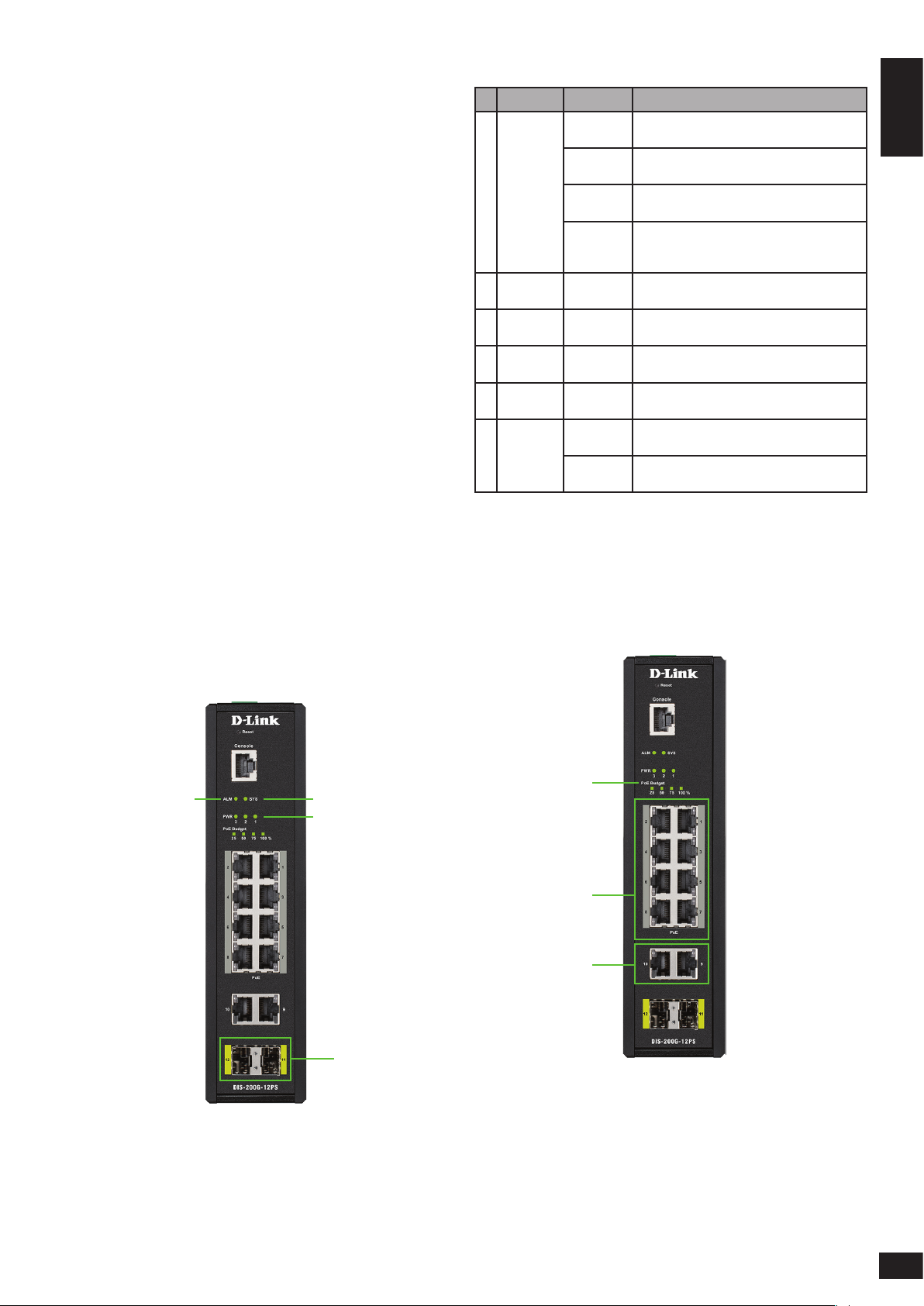
# LED Status Description
1 SYS
2 ALM
3 PWR 1
4 PWR 2
5 PWR 3
Ports
6
11 - 12
Solid
green
Blinking
green
Solid
amber
Blinking
amber
Solid
amber
Solid
green
Solid
green
Solid
green
Solid
green
Blinking
green
The DIS-200G is on and accepting web/CLI
connections.
A rmware update is in progress.
The DIS-200G is not ready for web/CLI
communication.
The DIS-200G is booting up or PoE has
failed during system operation (DIS-200G12PS/PSW models only).
The power supply to the DIS-200G has
failed.
Power source 1 is connected.
Power source 2 is connected.
Power source 3 is connected.
Port is connected at 1 Gbps.
There is activity on the port at 1 Gbps.
Table 1
Hardware Overview
LED Indicators
2
DIS-200G-12PS/PSW
1
1
3, 4, 5
2, 3
2
Figure 1
6
1
Page 4
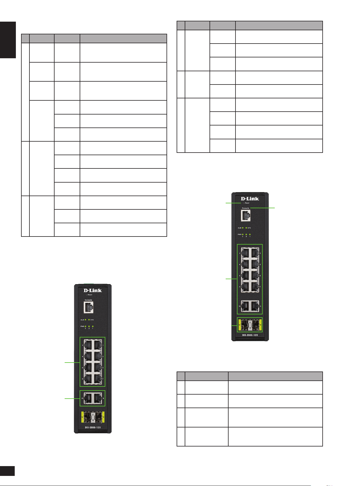
Figure 2
# LED Status Description
ENGLISH
1
2
3
PoE
Budget
100
PoE
Budget
75
PoE
Budget
50
PoE
Budget
25
Left:
Ports
1 - 10
Right:
Ports 1 - 8
Solid
green
Solid
green
Solid
green
Solid
green
Solid
amber
Blinking
amber
Solid
green
Blinking
green
Solid
amber
Blinking
amber
Solid
green
Solid
amber
Blinking
amber
The power budget is 100% and no PoE is
being used.
The power budget is between 100 and
75%.
The power budget is between 75 and 50%.
The power budget is between 50 and 25%.
The power budget is between 25 and 0%,
but still has more than 15.4 W remaining.
The power budget is between 25 and 0%
and has less than 15.4 W remaining.
Port is connected at 1 Gbps.
There is activity on the port at 1 Gbps.
Port is connected at 10/100 Mbps.
There is activity on the port at 10/100
Mbps.
The PoE output is using IEEE 802.3af/at
and is less than 15.4 W.
The PoE output is using IEEE 802.3at and is
between 15.4 and 30 W.
The PoE output on the port is over 30 W
and the port has been shut down.
# LED Status Description
1
2
3
Left:
Ports 1 - 8
Right:
Ports 1 - 8
Left:
Ports
9 - 10
Solid
green
Blinking
green
Solid
amber
Blinking
green
Blinking
amber
Solid
green
Blinking
green
Solid
amber
Blinking
amber
Port is connected at 1 Gbps.
The port is undergoing cable diagnostics.
Port is connected at 10/100 Mbps.
There is activity on the port at 1 Gbps.
There is activity on the port at 10/100
Mbps.
Port is connected at 1 Gbps.
There is activity on the port at 1 Gbps.
Port is connected at 10/100 Mbps.
There is activity on the port at 10/100
Mbps.
Table 3
Front Panel Connectors
1
2
DIS-200G-12S/SW
1, 2
3
Table 2
3
4
Figure 4
# Item Description
1 Reset
2 Console
3 Ports 1 to 10
4 Ports 11 to 12
This is the reset button which is used to
perform a factory reset.
This is a console port which is used to connect
to the DIS-200G using a RJ-45 to serial cable.
These are 10/100/1000 Mbps ports that can
be used to connect to any device using a
standard Category 5/5e RJ-45 Ethernet cable.
These are 1 Gbps SFP ports that can be used
to connect to other switches using compatible
SFP adapters and ber cable.
Table 4
Figure 3
2
Page 5
Rear Panel Connectors
Figure 5
requirements are investigated before mounting the
ENGLISH
DIS-200G, as access to the switch may be restricted
once it has been installed.
Mounting the Switch on a DIN Rail
Before beginning either mounting or removing the
1
DIS-200G from a DIN rail, please ensure that the
DIN rail is level and that the DIN rail mounting kit is
installed correctly on the DIS-200G.
# Item Description
1 Power input
This is used to connect an external power
adapter to the switch.
Table 5
Top Panel Connectors
1 2
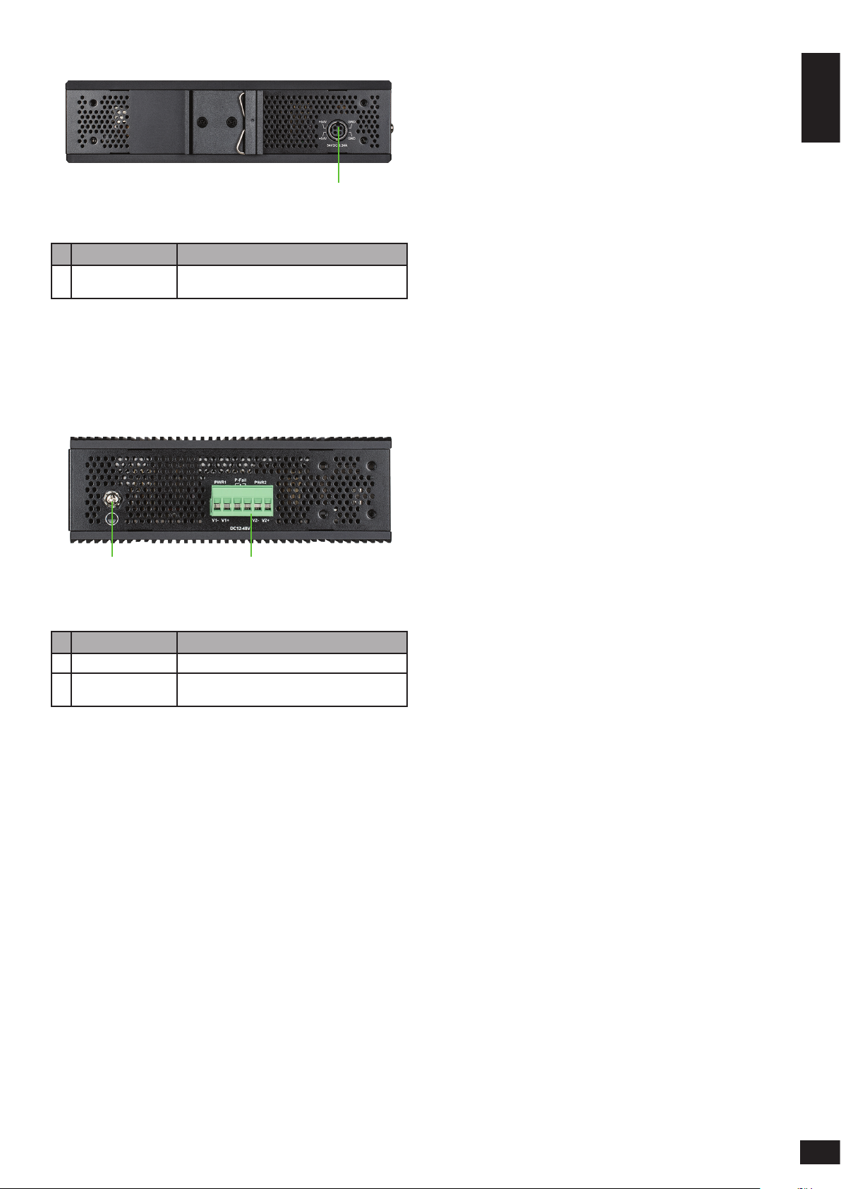
Figure 6
# Item Description
1 Switch ground This is used to connect the switch to ground.
2 Terminal block
This is used to connect the switch to external
power sources and relays.
Table 6
Hardware Installation
Use the following instructions to install the DIS-200G
on a DIN rail:
1. With the back of the DIS-200G facing the DIN
rail, lower the top part of the rail mounting kit
onto the DIN rail.
2. Push the DIS-200G vertically down and rotate the
bottom of the DIS-200G towards the DIN rail, to
attach the switch to the DIN rail.
Use the following instructions to remove the
DIS-200G from a DIN rail:
1. Push the DIS-200G vertically down to create
enough space at the bottom of the rail mounting
kit to remove the DIS-200G from the DIN rail.
2. Rotate the DIS-200G upwards to remove the
bottom of the rail mounting kit from the rail, and
lift the DIS-200G upwards to remove the whole
of the switch from the DIN rail.
Mounting the Switch on a Wall
The DIS-200G can be installed on a solid surface by
using the included wall mounting plates attached
to the back of the switch. It can also be mounted
using the in-built screw hooks on the underneath
of the switch.
Before You Begin
Observe the following precautions to help prevent
shutdowns, equipment failures, and personal injury:
• Install the DIS-200G in a cool and dry place. Refer
to the technical specications in the user manual
for the acceptable operating temperature and
humidity ranges.
• Leave at least 10 cm of space at the top, rear and
bottom of the switch for ventilation.
• Visually inspect the power connector and make
sure that it is fully secured to the power cord.
• Do not stack any devices on top of the switch.
It is also recommended that power and grounding
Using the Wall Mounting Brackets
Use the following instructions to install the DIS-200G
on a wall:
1. Remove the DIN rail mounting kit from the back
of the DIS-200G (if present).
2. Align the cross-section of the mounting plates
with the openings on the back of the switch and
secure the plates to the switch with the included
screws.
3. Place the switch with the mounting brackets
installed on the location where you want to
mount it, and use the mounting brackets as a
guide to mark where to drill the screw holes.
4. Drill holes on the marks and insert wall anchors
appropriate for the material of the wall.
3
Page 6

5. Align the switch with the wall anchors and secure
the switch to the wall using the appropriate
screws for the wall anchors.
ENGLISH
Mounting the Switch in a Rack
The DIS-200G can be mounted in a standard 19”
server rack by using the included rack mounting
brackets (optional).
Use the following instructions to install the switch
in a rack:
1. Attach the included mounting brackets to each
side of the DIS-200G using the provided screws.
Figure 7
Using the Screw Hooks
Use the following instructions to mount the DIS-200G
on a wall using the screw hooks on the underneath
of the switch:
6. Mark two points on the surface where you wish
to mount the switch 60 mm apart.
7. Drill holes on the marks and insert wall anchors
appropriate for the material of the wall.
8. Insert screws into the wall anchors, leaving
roughly 4.50 mm of distance from the wall for
the switch to be mounted.
9. Mount the DIS-200G on the screws using the
screw hooks on the underneath of the switch.
Figure 9
2. Use the screws that were provided with the rack
to install the DIS-200G in the rack.
Figure 10
Grounding the Switch
To use the DIS-200G safely, it needs to be grounded.
Please complete these steps before powering-on
the switch.
Note:
The grounding screw of the chassis must be properly
connected to the protective earthing of building
in compliance with local regulatory guidelines by
using a green-and-yellow grounding cable with
the minimum wire gauge 0.5 mm2 or 20 AWG
Use the following instructions to ground the
DIS-200G:
1. Remove the grounding screw from the top of the
DIS-200G and place the grounding cable lug ring
on top of the grounding screw opening.
4
Figure 8
Page 7

2. Insert the grounding screw back into the
grounding screw opening and use a screwdriver
to tighten the grounding screw, securing the
grounding cable to the DIS-200G.
3. Attach the terminal lug ring at the other end of the
grounding cable to an appropriate grounding source.
4. Verify that the connection between the
grounding connector on the DIS-200G and the
grounding source is secure.
Connecting to a Power Source
The DIS-200G can be powered using a power
adapter (optional) or by using the in-built terminal
connector. This allows dual power inputs, using wires
from the power source(s) screwed-in to the terminal
connections.
block. Note that two power sources can be used;
one inserted into V1-/V1+ (labeled PWR1) and
the other inserted into V2-/V2+ (labeled PWR2).
If you only wish to use one power source, insert
the wires into V1-/V1+ (PWR1). This diagram is
also provided on the DIS-200G:
Figure 12
ENGLISH
Using the Power Adapter (Optional)
Use the following instructions to power the DIS-200G
using the power adapter (optional):
1. Connect the supplied power adapter to the
power connector on the back of the DIS-200G.
Connect the other end of the power adapter to
a mains power source.
Figure 11
2. Use a lever to remove the terminal block from
the switch.
Figure 13
3. Using a flat head screwdriver, loosen the
connections in the terminal block by un-screwing
the terminal connections that you wish to use.
4. Insert the wires into the terminal connections
and use the screwdriver to tighten the screws
to secure the wires.
Using the Terminal Connections
Before proceeding, ensure that all power sources
have been disconnected from the DIS-200G, and that
the power source you are wiring to the DIS-200G is
also disconnected.
Use the following instructions to power the DIS-200G
using the terminal connections:
1. Before continuing, consult the diagram below to
decide which wires from the power source need
to connect to which contacts on the terminal
Figure 14
5. Re-insert the terminal block into the terminal
block socket on the DIS-200G.
5
Page 8

Management Options
D-Link Network Assistant (depend-
The DIS-200G can be managed by using the Web
User Interface (Web UI), D-Link Network Assistant
ENGLISH
(DNA), console port, Telnet, or Simple Network
Management Protocol (SNMP) management
interfaces.
If you wish to manage a single D-Link switch, the
Web UI may be the best option. Each switch must
be assigned its own IP address, which is used for
communication with the management PC. However,
if you wish to manage multiple D-Link switches, DNA
may be the best option. You do not need to change
the IP address of your PC and it makes the initial set
up of multiple switches easy.
Please refer to the following installation instructions
to get started with the Web UI, DNA, console port,
Telnet, and SNMP management interfaces.
Web User Interface
Once the switch has been successfully installed, you
can begin conguration, monitor the LED panel,
and display graphical statistics using a web browser.
Supported browsers include: Microsoft® Internet
Explorer, Firefox, Chrome, and Safari.
You need the following equipment to access the
Web UI of your device:
• A PC with an RJ-45 Ethernet connection
• A standard Ethernet cable
1. Connect the Ethernet cable to any of the ports
on the switch’s front panel and to the Ethernet
port on the PC.
2. Congure the PC’s IP address to be in the same
network segment as the switch. The switch’s
default IP address is 10.90.90.90, with subnet
mask 255.0.0.0. For example, to connect to the
switch using the default settings, your PC should
have an IP address in the range: 10.0-255.0-255.0254 and a subnet mask of 255.0.0.0.
3. Open a web browser and enter http://10.90.90.90/
in the address box. Note: The Web UI can also be
accessed through DNA, by clicking the switch’s
IP in the device list.
ing on the purchased model)
D-Link Network Assistant (DNA) is a program that is
used to discover switches which are in the same Layer
2 network segment as your PC. Please refer to the
following steps to get started with DNA.
1. Go to http://tools.dlink.com/intro/dna/
2. Select “Free Download” button to open DNA
download page for download
Note: for Managed Switch, users need to enable
D-Link Discovery Protocol (DDP) and create a user
name and password to be able to log in to DNA.”
Console
To connect to the switch’s console, use the supplied
cable to connect to the switch’s console port.
This cable is a RS-232 serial to RJ-45 connector
cable designed for use with the switch. A terminal
emulation program is required to connect to the
console port on the switch. These are widely available
and can be easily downloaded from the Internet.
Using following steps to connect to switch’s console
port:
1. Connect the RS-232 serial interface to the serial
port of the management PC.
2. Connect the RJ-45 interface to the console port
of the switch.
3. Open a terminal emulation program on the
management PC and congure the properties
of the connection as follows:
• The speed should be 115200 baud.
• The data bits should be 8.
• The parity should be None.
• The stop bits should be 1.
• The ow control should be None.
4. Connect to the switch and the Command
Line Interface (CLI) should be available. When
prompted to log in, enter admin as the default
user name and password.
4. Log in to the switch. To do this, enter admin as
the default user name and password and click
OK.
6
Telnet
To connect to the switch using Telnet, a Telnet client
is required. This may be included with your operating
Page 9

system, or can be easily downloaded from the
Internet.
Before connecting to the switch, ensure that your PC
has an IP address in the same range as the switch.
Follow the instructions in the Web User Interface
section for more information on how to do this.
1. Launch the Telnet software and connect to the
IP address of the switch.
Additional Information
You can refer to the user manual or visit
http://support.dlink.com/ for more support.
Online Support
If there are any issues that are not in the user
manual, please visit http://support.dlink.com/
which will direct you to your appropriate local
D-Link support website.
ENGLISH
2. When you are prompted for a username and
password, enter admin as the default username
and password.
SNMP
You can manage the switch with D-Link D-View, or
any other SNMP-compatible program. The SNMP
function is disabled by default and must be enabled
on the switch rst by using either the Web UI, DNA,
the console, or Telnet.
D-View SNMP Network Management System is
a comprehensive standard-based management
tool designed to centrally manage critical network
infrastructure. D-View provides useful tools to allow
network administrators to eectively manage device
congurations, fault tolerance, performance, and
security.
D-Link oers a free version of D-View which can
be used to manage up to 25 devices. Visit
http://dview.dlink.com/ to download it and
get more information.
Warranty Information
Visit http://warranty.dlink.com/ to view the
D-Link Limited Lifetime Warranty information.
Device Reset
If you have any problems accessing the DIS-200G,
it can be reset using the following instructions:
1. Press and hold the reset button for 6 to 10
seconds. All the LEDs on the DIS-200G will light
amber. When this happens, release the reset
button and the DIS-200G will be reset to factory
defaults.
Note: holding the reset button for more than 11
seconds will cause all LEDs on the DIS-200G to
light green. Holding the reset button for a further
2 seconds will put the DIS-200G into boot loader
mode.
7
Page 10

Regulatory Statements
Federal Communication Commission
Interference Statement
This equipment has been tested and found to comply with the
limits for a Class A digital device, pursuant to part 15 of the FCC
Rules. These limits are designed to provide reasonable protection
against harmful interference when the equipment is operated
in a commercial environment. This equipment generates, uses,
and can radiate radio frequency energy and, if not installed and
used in accordance with the instruction manual, may cause
harmful interference to radio communications. Operation of
this equipment in a residential area is likely to cause harmful
interference in which case the user will be required to correct the
interference at his own expense.
Non-modication Statement
Any changes or modications not expressly approved by the
party responsible for compliance could void the user's authority
to operate the equipment.
Caution
This device complies with Part 15 of the FCC Rules. Operation is
subject to the following two conditions:
(1) This device may not cause harmful interference, and (2)
this device must accept any interference received, including
interference that may cause undesired operation.
Industry Canada Statement:
This Class A digital apparatus complies with Canadian ICES-003.
Cet appareil numérique de la classe A est conforme à la norme
NMB-003 du Canada.
Japan Voluntary Control Council for
Interference Statement
この装置は、クラス A 情報技術装置です。 この
装置を家庭環境で使用すると電波妨害を引き
起こすことがあります。 この場合には使用者が
適切な対策を講ずるよう要求されることがあります。
VCCI-A
警告使用者:
此為甲類的資訊技術設備,在居住環境中使用時,可能會造
成射頻擾動,在這種情況下,使用者會被要求採取某些適當
的對策。
Warning: This is a class A product. In a domestic environment this
product may cause radio interference in which case the user may
be required to take adequate measures.
CE EMI Class A Warning
This equipment is compliant with Class A of CISPR 32. In a
residential environment this equipment may cause radio
interference.
Page 11

Notes
Page 12

Notes
Page 13

Notes
Page 14

Notes
Page 15

Page 16

Ver. 1.03(WW)_130x183
20/20/02/27
 Loading...