

Page 1
Page 2

Table of Contents D-Link Web Smart Switch User Manual
Table of Contents
Table of Contents ............................................................................................................................................. i
About This Guide ............................................................................................................................................. 1
Terms/Usage .................................................................................................................................................. 1
Copyright and Trademarks ............................................................................................................................ 1
1 Product Introduction ................................................................................................................................... 2
DGS-1500-20 ................................................................................................................................................. 3
Front Panel ................................................................................................................................................. 3
Rear Panel .................................................................................................................................................. 3
DGS-1500-28 ................................................................................................................................................. 3
Front Panel ................................................................................................................................................. 3
Rear Panel .................................................................................................................................................. 4
DGS-1500-28P ............................................................................................................................................... 4
Front Panel ................................................................................................................................................. 4
Rear Panel .................................................................................................................................................. 5
DGS-1500-52 ................................................................................................................................................. 5
Front Panel ................................................................................................................................................. 5
Rear Panel .................................................................................................................................................. 5
2 Hardware Installation .................................................................................................................................. 6
Step 1: Unpacking .......................................................................................................................................... 6
Step 2: Switch Installation .............................................................................................................................. 6
Desktop or Shelf Installation ....................................................................................................................... 6
Rack Installation ......................................................................................................................................... 6
Step 3 – Plugging in the AC Power Cord ....................................................................................................... 7
Power Failure ............................................................................................................................................. 8
3 Getting Started ............................................................................................................................................. 9
Management Options ..................................................................................................................................... 9
Using Web-based Management .................................................................................................................... 9
Supported Web Browsers .......................................................................................................................... 9
Connecting to the Switch ............................................................................................................................ 9
Login Web-based Management ............................................................................................................... 10
Smart Wizard ............................................................................................................................................... 10
Web-based Management ............................................................................................................................. 10
SmartConsole Utility ..................................................................................................................................... 10
4 SmartConsole Utility ................................................................................................................................. 12
SmartConsole Settings ................................................................................................................................ 12
Utility Settings ........................................................................................................................................... 12
Log ............................................................................................................................................................ 12
Trap .......................................................................................................................................................... 13
Monitor List ............................................................................................................................................... 13
About ........................................................................................................................................................ 14
Device Configuration .................................................................................................................................... 14
Add(+), Delete(-) and Discover the device ............................................................................................... 16
Device List .................................................................................................................................................... 17
5 Configuration ............................................................................................................................................. 19
Smart Wizard Configuration ......................................................................................................................... 19
IPv4 Information ....................................................................................................................................... 19
Password Settings .................................................................................................................................... 19
ii
Page 3

Table of Contents D-Link Web Smart Switch User Manual
SNMP Settings ......................................................................................................................................... 20
Web-based Management ......................................................................................................................... 21
Tool Bar > Save Menu ................................................................................................................................. 22
Save Configuration ................................................................................................................................... 22
Save Log .................................................................................................................................................. 22
Tool Bar > Tool Menu .................................................................................................................................. 22
Reset ........................................................................................................................................................ 22
Reset System ........................................................................................................................................... 22
Reboot Device .......................................................................................................................................... 23
Configuration Backup and Restore .......................................................................................................... 23
Firmware Backup and Upgrade ................................................................................................................ 23
Tool Bar > Smart Wizard .............................................................................................................................. 24
Tool Bar > Online Help ................................................................................................................................. 24
Function Tree ............................................................................................................................................... 26
Device Information.................................................................................................................................... 26
System > System Settings ....................................................................................................................... 27
System > Password .................................................................................................................................. 28
System > Port Settings ............................................................................................................................. 28
System > DHCP Auto Configuration ........................................................................................................ 29
System > SysLog Host Settings ............................................................................................................... 30
System > Time Profile .............................................................................................................................. 30
System > Power Saving ........................................................................................................................... 31
System > IEEE802.3az EEE settings ....................................................................................................... 31
VLAN > 802.1Q VLAN .............................................................................................................................. 32
VLAN > VLAN Status ............................................................................................................................... 33
VLAN > GVRP > GVRP Global Settings .................................................................................................. 34
VLAN > GVRP > GVRP Port Settings ...................................................................................................... 34
VLAN > Voice VLAN > Voice VLAN Global Settings ............................................................................... 35
VLAN > Voice VLAN > Voice VLAN Port Settings ................................................................................... 36
VLAN > Voice VLAN > Voice Device List ................................................................................................. 37
VLAN > Auto Surveillance VLAN ............................................................................................................. 37
L2 Functions > Jumbo Frame................................................................................................................... 38
L2 Functions > Port Mirroring ................................................................................................................... 38
L2 Functions > Loopback Detection ......................................................................................................... 39
L2 Functions > MAC Address Table > Static MAC .................................................................................. 40
L2 Functions > MAC Address Table > Dynamic Forwarding Table ......................................................... 40
L2 Functions > Spanning Tree > STP Bridge Global Settings ................................................................. 41
L2 Functions > Spanning Tree > STP Port Settings ................................................................................ 42
L2 Functions > Spanning Tree > MST Configuration Identification ......................................................... 43
L2 Functions > Spanning Tree > STP Instance Settings ......................................................................... 44
L2 Functions > Spanning Tree > MSTP Port Information ........................................................................ 45
L2 Functions > Link Aggregation > Port Trunking .................................................................................... 45
L2 Functions > Link Aggregation > LACP Port Settings .......................................................................... 46
L2 Functions > Multicast > IGMP Snooping ............................................................................................. 46
L2 Functions > Multicast > Multicast Forwarding ..................................................................................... 48
L2 Functions > Multicast > Multicast Filtering Mode ................................................................................ 49
L2 Functions > SNTP > Time Settings ..................................................................................................... 49
L2 Functions > SNTP > TimeZone Settings ............................................................................................. 50
L2 Functions > LLDP > LLDP Global Settings ......................................................................................... 50
iiii
Page 4

Table of Contents D-Link Web Smart Switch User Manual
L2 Functions > LLDP > LLDP Port Settings ............................................................................................. 51
L2 Functions > LLDP > 802.1 Extension TLV .......................................................................................... 52
L2 Functions > LLDP > 802.3 Extension TLV .......................................................................................... 53
L2 Functions > LLDP > LLDP Management Address Settings ................................................................ 53
L2 Functions > LLDP > LLDP Management Address Table .................................................................... 54
L2 Functions > LLDP > LLDP Local Port Table ....................................................................................... 54
L2 Functions > LLDP > LLDP Remote Port Table ................................................................................... 55
L2 Functions > LLDP > LLDP Statistics ................................................................................................... 56
L3 Functions > IP Interface ...................................................................................................................... 57
L3 Functions > IPv6 Neighbor Settings .................................................................................................... 57
L3 Functions > Static Route ..................................................................................................................... 58
L3 Functions > Routing Table Finder ....................................................................................................... 58
L3 Functions > IPv6 Static Route ............................................................................................................. 58
L3 Functions > IPv6 Routing Table Finder ............................................................................................... 59
L3 Functions > ARP > ARP Table Global Settings .................................................................................. 59
L3 Functions > ARP > Static ARP Settings .............................................................................................. 60
L3 Functions > ARP > Gratuitous ARP .................................................................................................... 60
L3 Functions > Single IP Management > SIM Global Settings ................................................................ 60
QoS > Bandwidth Control ......................................................................................................................... 61
QoS > 802.1p/DSCP/ToS ......................................................................................................................... 62
QoS > TCP/UDP Port Priority Settings .................................................................................................... 62
QoS > IPv6 Traffic Class Priority Settings ............................................................................................... 63
Security > Trusted Host ............................................................................................................................ 63
Security > Port Security ............................................................................................................................ 63
Security > Traffic Segmentation ............................................................................................................... 64
Security > Safeguard Engine.................................................................................................................... 65
Security > Storm Control .......................................................................................................................... 65
Security > ARP Spoofing Prevention ....................................................................................................... 65
Security > DHCP Server Screening ......................................................................................................... 66
Security > SSL .......................................................................................................................................... 66
Security > SSH > SSH Settings ............................................................................................................... 67
Security > SSH > SSH Authmode and Algorithm Settings....................................................................... 67
Security > SSH > SSH User Authentication Lists .................................................................................... 68
Security > Smart Binding > Smart Binding Settings ................................................................................. 69
Security > Smart Binding > Smart Binding ............................................................................................... 70
Security > Smart Binding > White List ...................................................................................................... 70
Security > Smart Binding > Black List ...................................................................................................... 70
AAA > RADIUS Server ............................................................................................................................. 71
AAA > 802.1X > 802.1X Global Settings .................................................................................................. 72
AAA > 802.1X > 802.1X Port Settings...................................................................................................... 72
AAA > 802.1X > 802.1X User ................................................................................................................... 73
ACL > ACL Wizard ................................................................................................................................... 73
ACL > Access Profile List ......................................................................................................................... 75
ACL > ACL Finder .................................................................................................................................... 85
PoE > PoE Global Settings (DGS-1500-28P only) .................................................................................. 85
PoE > PoE Port Settings (DGS-1500-28P only) ...................................................................................... 86
SNMP > Trap to SmartConsole ................................................................................................................ 87
SNMP > SNMP > SNMP Global Settings ................................................................................................ 87
SNMP > SNMP > SNMP User ................................................................................................................. 88
iii
Page 5

Table of Contents D-Link Web Smart Switch User Manual
SNMP > SNMP > SNMP Group ............................................................................................................... 89
SNMP > SNMP > SNMP View ................................................................................................................. 89
SNMP > SNMP > SNMP Community ....................................................................................................... 90
SNMP > SNMP > SNMP Host .................................................................................................................. 90
SNMP > SNMP > SNMP Engine ID ......................................................................................................... 90
SNMP > RMON > RMON Global Settings ............................................................................................... 91
SNMP > RMON > RMON Statistics ......................................................................................................... 91
SNMP > RMON > RMON History ............................................................................................................. 91
SNMP > RMON > RMON Alarm .............................................................................................................. 91
SNMP > RMON > RMON Event ............................................................................................................... 92
Monitoring > Port Statistics....................................................................................................................... 93
Monitoring > Cable Diagnostics ............................................................................................................... 93
Monitoring > System Log .......................................................................................................................... 94
6 Command Line Interface ........................................................................................................................... 95
To connect a switch via TELNET: ................................................................................................................ 95
Logging on to the Command Line Interface: ................................................................................................ 95
CLI Commands: ........................................................................................................................................... 95
? ................................................................................................................................................................ 96
download .................................................................................................................................................. 96
upload ....................................................................................................................................................... 97
config ipif .................................................................................................................................................. 98
logout ........................................................................................................................................................ 99
ping ........................................................................................................................................................... 99
ping6 ....................................................................................................................................................... 100
reboot ..................................................................................................................................................... 100
reset config ............................................................................................................................................. 101
show ipif .................................................................................................................................................. 101
show switch ............................................................................................................................................ 102
config account admin password ............................................................................................................. 102
save ........................................................................................................................................................ 102
debug info ............................................................................................................................................... 103
Appendix A - Technical Specifications ..................................................................................................... 105
Hardware Specifications ............................................................................................................................ 105
Key Components / Performance ............................................................................................................ 105
Port Functions ........................................................................................................................................ 105
Physical & Environment ......................................................................................................................... 105
RPS Support ........................................................................................................................................... 105
Emission (EMI) Certifications ................................................................................................................. 105
Safety Certifications................................................................................................................................ 105
Features ..................................................................................................................................................... 105
L2 Features ............................................................................................................................................ 105
L3 Features ............................................................................................................................................ 106
D-Link Green Technology ...................................................................................................................... 106
VLAN ...................................................................................................................................................... 106
QoS (Quality of Service) ......................................................................................................................... 106
Security ................................................................................................................................................... 106
Management ........................................................................................................................................... 107
iivv
Page 6
About This Guide D-Link Web Smart Switch User Manual
he model you have purchased may
information that
About This Guide
This guide provides instructions to install the D-Link Gigabit SmartPro Switch DGS-1500-20/28/28P/52, how
to use the SmartConsole Utility, and to configure Web-based Management step-by-step.
Note: T
appear slightly different from the illustrations
shown in the document. Refer to the Product
Instruction and Technical Specification sections
for detailed information about your switch, its
components, network connections, and technical
specifications.
This guide is mainly divided into four parts:
1. Hardware Installation: Step-by-step hardware installation procedures.
2. Getting Started: A startup guide for basic switch installation and settings.
3. Smart Console Utility: An introduction to the central management system.
4. Configuration: Information about the function descriptions and configuration settings.
Terms/Usage
In this guide, the term “Switch” (first letter capitalized) refers to the SmartPro Switch, and “switch” (first letter
lower case) refers to other Ethernet switches. Some technologies refer to terms “switch”, “bridge” and
“switching hubs” interchangeably, and both are commonly accepted for Ethernet switches.
A NOTE indicates important
helps a better use of the device.
A CAUTION indicates potential property damage
or personal injury.
Copyright and Trademarks
Information in this document is subjected to change without notice.
© 2011 D-Link Corporation. All rights reserved.
Reproduction in any manner whatever without the written permission of D-Link Corporation is strictly
forbidden.
Trademarks used in this text: D-Link and the D-LINK logo are trademarks of D-Link Corporation; Microsoft
and Windows are registered trademarks of Microsoft Corporation.
Other trademarks and trade names may be used in this document to refer to either the entities claiming the
marks and names or their products. D-Link Corporation disclaims any proprietary interest in trademarks and
trade names other than its own.
1
Page 7

1 Product Introduction D-Link Web Smart Switch User Manual
1 Product Introduction
Thank you and congratulations on your purchase of D-Link SmartPro Switch Products.
D-Link's next generation SmartPro Ethernet switch series blends plug-and-play simplicity with exceptional
value and reliability for small and medium-sized business (SMB) networking. All models are housed in a new
style rack-mount metal case with easy-to-view front panel diagnostic LEDs, and provides advance features
including four 1000BASE-X SFP slots for fiber connection, network security, traffic segmentation, QoS and
versatile management.
Flexible Port Configurations. Four port densities are available for selection: 16, 24, and 48 Gigabit
Ethernet ports. Supporting auto-detection of MDI/MDIX, these switches bring inexpensive and easy Ethernet
connection to the desktops. DGS-1500 series provides 4 SFP slots, which supports 1000M fiber connections
with appropriate fiber transceivers. DGS-1500-28P provides 4 combo SFP slots, which supports both 1000M
and 100M fiber connections with appropriate fiber transceivers. The first 24 ports also support up to 15.4 or
30 watts PoE power for the connections of wireless access points, IP phones and other PoE-supported
devices, allowing them to be deployed at difficult places such as on high walls and ceilings, where AC power
outlets are not readily available.
D-Link Green Technology. D-Link Green devices are about providing eco-friendly alternatives without
compromising performance. D-Link Green Technology includes a number of innovations to reduce energy
consumption on DGS-1500 series such as reducing power when a port does not have a device attached, or
adjusting the power usage according to the Ethernet cable connected to it. For PoE model such as DGS1500-28P, D-Link Green Technology offers Time-based PoE feature to shut down per port power off working
hours.
Extensive Layer 2 Features. Implemented as complete L2 devices, these switches include functions such
as IGMP snooping, port mirroring, Spanning Tree, 802.3ad LACP, SNTP, LLDP and Loopback Detection to
enhance performance and network resiliency.
Extensive Layer 3 Features. Implemented as complete L3 devices, these switches include functions such
as IP interface, static route, IPv6 Static Route, ARP and single IP management to enhance performance and
network resiliency.
QoS. The switches supports bandwidth control and 802.1p priority queues, enabling users to run bandwidthsensitive applications such as streaming multimedia by prioritizing that traffic in network. These functions
allow switches to work seamlessly with VLAN and 802.1p traffic and IPv6 traffic class priority in the network.
Network Security. D-Link’s innovative Safeguard Engine function protects the switches against traffic
flooding caused by virus attacks. Additional features Storm Control can help to keep the network from being
overwhelmed by abnormal traffic. Port Security is another simple but useful authentication method to
maintain the network device integrity. Also supports DHCP Server Screening, SSL, SSH and Smart Binding
features.
Versatile Management. The new generation of D-Link Web Smart Switches provides growing businesses
with a simple and easy management of their network, using an intuitive SmartConsole utility or a Web-Based
management interface that allows administrators to remotely control their network down to the port level. The
SmartConsole easily allows customers to discover multiple D-Link web smart switches with the same L2
network segment connected to the user’s local PC. With this utility, users do not need to change the IP
address of the PC and provide easy initial settings of the smart switches. The switches within the same L2
network segment connected to the user’s local PC are displayed on the screen for instant access. It allows
extensive switch configuration settings, and basic configuration of discovered devices, such as a password
change or firmware upgrade.
Users can also access the switch via TELNET. Some basic tasks can be performed such as changing the
Switch IP address, resetting the settings to factory defaults, setting the administrator password, rebooting the
Switch, or upgrading the Switch firmware by using the Command Line Interface (CLI).
2
Page 8
1 Product Introduction D-Link Web Smart Switch User Manual
In addition, users can utilize the SNMP MIB (Management Information Base) to poll the switches for
information about the status, or send out traps of abnormal events. SNMP support allows users to integrate
the switches with other third-party devices for management in an SNMP-enabled environment. D-Link Web
Smart Switches also come with the D-View plug-in module that works with D-View 6 SNMP Management
Software, and provides easy-to-use graphic interface and facilitates the operation efficiency.
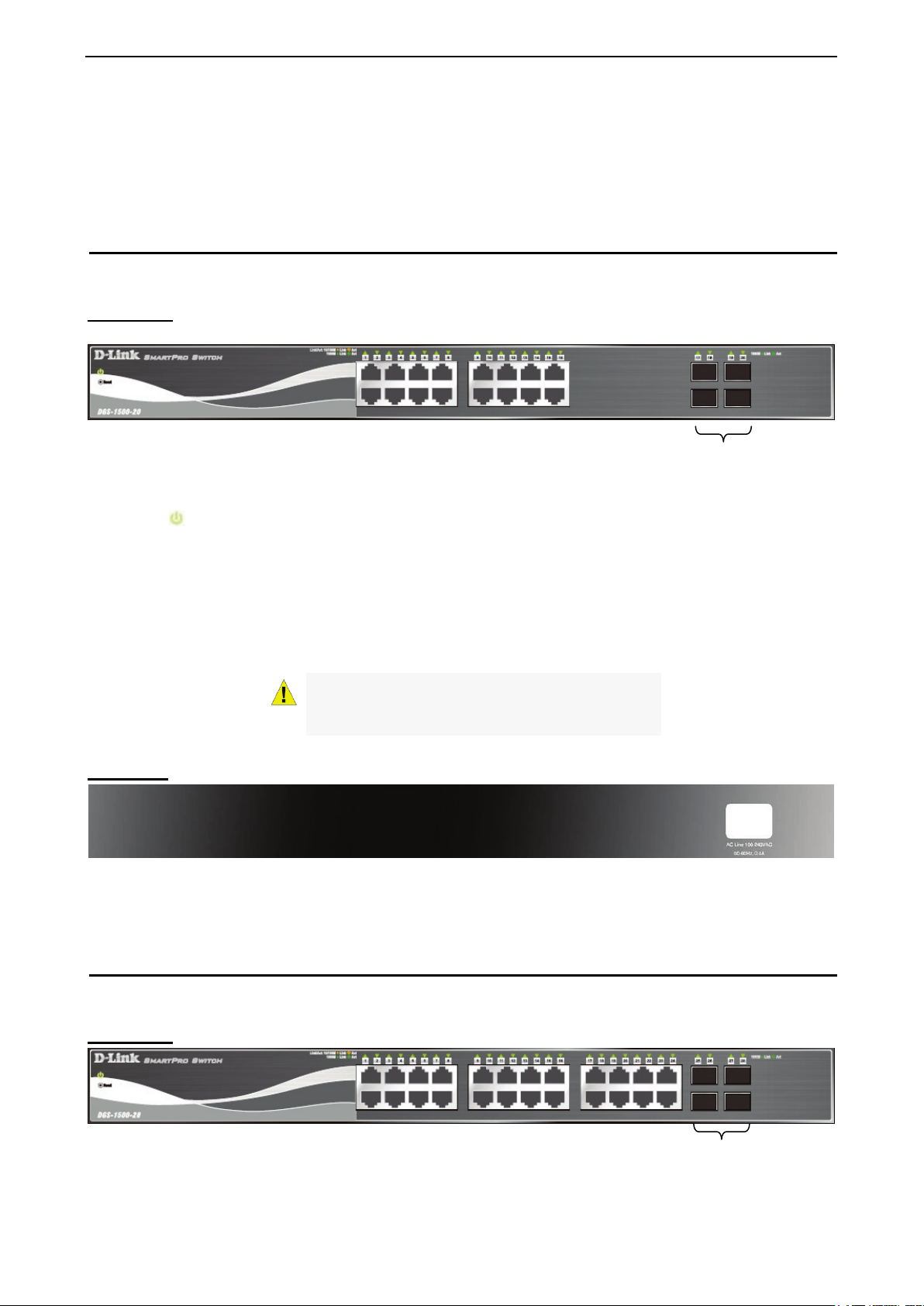
DGS-1500-20
16-Port 10/100/1000Mbps plus 4 1000Base-T/SFP ports SmartPro Switch.
Front Panel
Figure 1.1 – DGS-1500-20 Front Panel
Power LED
: The Power LED lights up when the Switch is connected to a power source.
Reset: By pressing the Reset button, the Switch will change back to the default configuration and all
changes will be lost.
Port Link/Act/Speed LED (1-16, 17F, 18F, 19F, 20F): The port LEDs indicate a network link through the
corresponding port. Blinking indicates the Switch is either sending or receiving data to the port. When the
port LED glows in amber, it indicates the port is running on 10M or 100M. When the port LED glows in green,
it is running on 1000Mbps.
SFP ports for optical transceivers
CAUTION: The MiniGBIC ports should use UL
listed Optical Transceiver product, Rated Laser
Class I. 3.3Vdc
Rear Panel
Figure 1.2 – DGS-1500-20 Rear Panel
Power: The power port is where to connect the AC power cord.
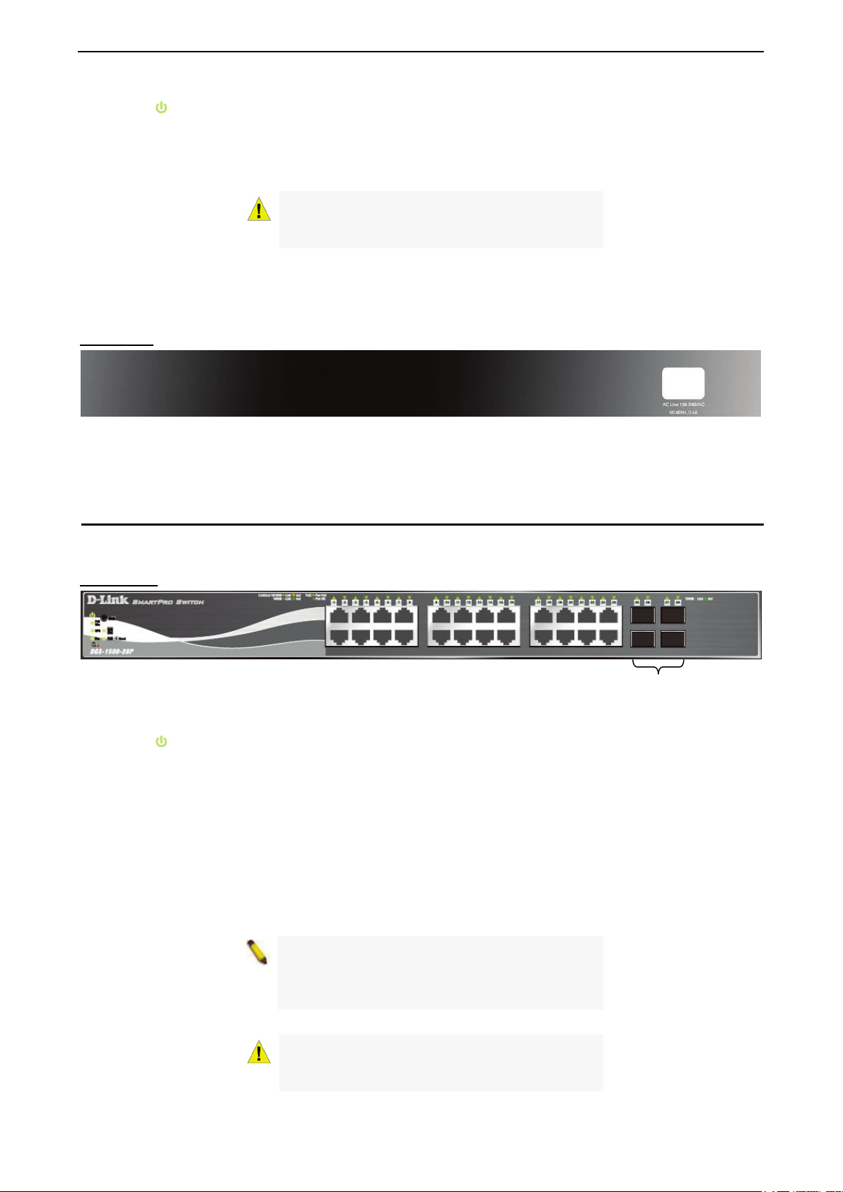
DGS-1500-28
24-Port 10/100/1000Mbps plus 4 1000Base-T/SFP ports SmartPro Switch.
Front Panel
Figure 1.3 – DGS-1500-28 Front Panel
SFP ports for optical transceivers
33
Page 9
1 Product Introduction D-Link Web Smart Switch User Manual
Power LED
: The Power LED lights up when the Switch is connected to a power source.
Port Link/Act/Speed LED (1-24, 25F, 26F, 27F, 28F): The Link/Act/Speed LED flashes, which indicates a
network link through the corresponding port. Blinking indicates that the Switch is either sending or receiving
data to the port. When a port has an amber light, this indicates that the port is running on 10M or 100M.
When it has a green light it is running on 1000M.
CAUTION: The MiniGBIC ports should use UL
listed Optical Transceiver product, Rated Laser
Class I. 3.3Vdc.
Reset: By pressing the Reset button, the Switch will change back to the default configuration and all
changes will be lost.
Rear Panel
Figure 1.4 – DGS-1500-28 Rear Panel
Power: The power port is where to connect the AC power cord.
DGS-1500-28P
24-Port 10/100/1000Mbps plus 4 1000Base-T/SFP ports SmartPro PoE Switch.
Front Panel
Figure 1.5 – DGS-1500-28P Front Panel
SFP ports for optical transceivers
Power LED
: The Power LED lights up when the Switch is connected to a power source.
Pwr Max: The Pwr Max LED lights up when the Switch reaches the maximum power budget defined by the
administrator via PoE System Settings page of Web GUI or the default power budget of 78 Watts.
Reset: By pressing the Reset button, the Switch will change back to the default configuration and all
changes will be lost.
Mode: By pressing the Mode button, the Port LED will switch between Link/Act and PoE modes.
Port Link/Act/Speed LED (1-24, 25F, 26F, 27F, 28F): The Link/Act/Speed LED flashes, which indicates a
network link through the corresponding port. Blinking indicates that the Switch is either sending or receiving
data to the port. When a port has an amber light, this indicates that the port is running on 10M or 100M.
When it has a green light it is running on 1000Mbps.
Fan: The Fan LED lights green when fans work well, and lights red when fans fail.
NOTE: On DGS-1500-28P, the SFP ports are
shared with normal RJ-45 ports 25 to 28. When
optical transceiver is inserted to SFP port and
link up, the RJ-45 port cannot be used.
CAUTION: The MiniGBIC ports should use UL
listed Optical Transceiver product, Rated Laser
Class I. 3.3Vdc.
4
Page 10
1 Product Introduction D-Link Web Smart Switch User Manual
SFP ports for optical transceivers
Port PoE LED (1-24): When mode LED lights up in PoE mode, the port LEDs indicate powering status over
the corresponding port.
Rear Panel
Figure 1.6 – DGS-1500-28P Rear Panel
Power: The power port is where to connect the AC power cord.
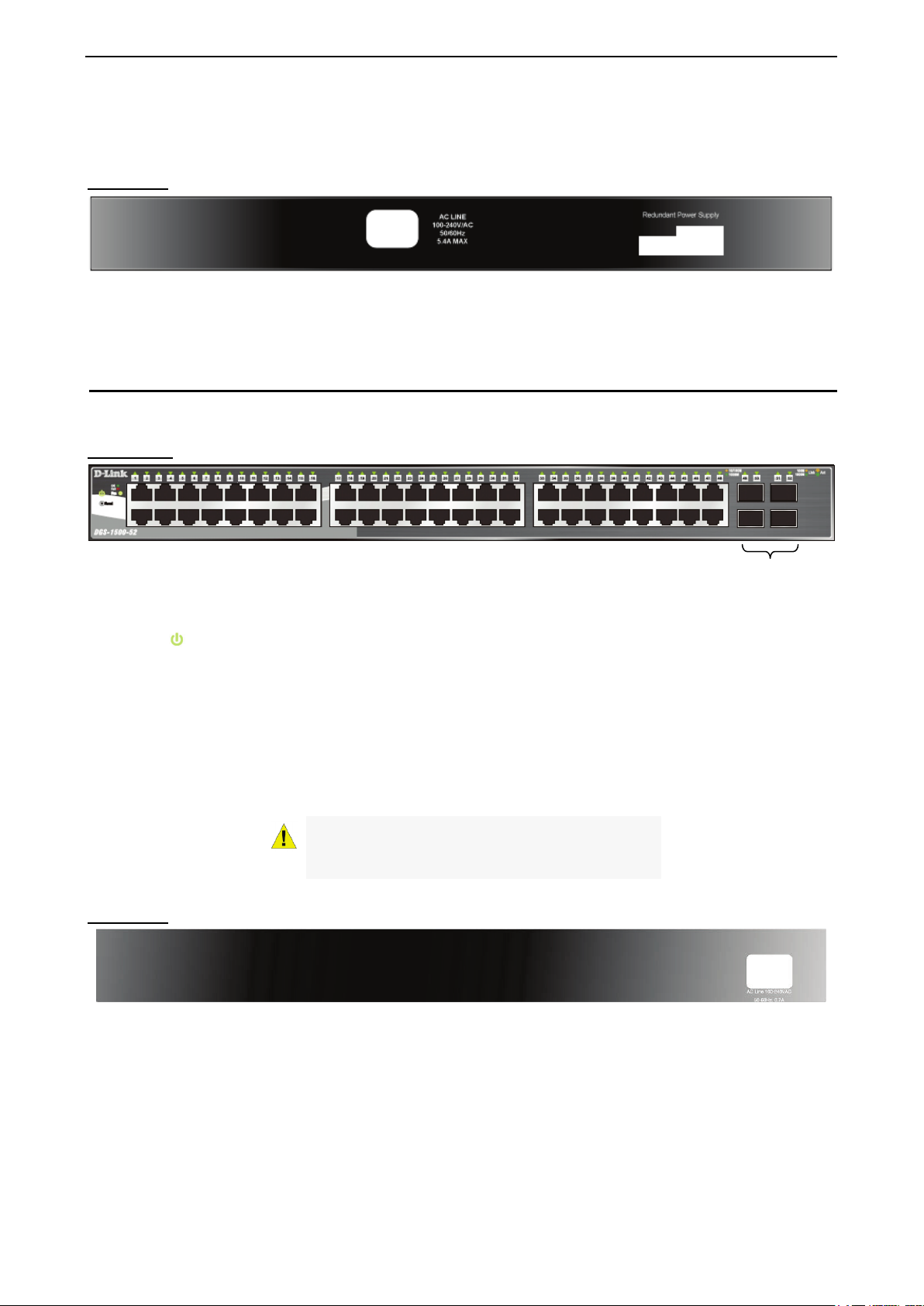
DGS-1500-52
48-Port 10/100/1000Mbps plus 4 100/1000FX SFP Slot SmartPro Switch.
Front Panel
Figure 1.7 – DGS-1500-52 Front Panel
Power LED
: The Power LED lights up when the Switch is connected to a power source.
Port Link/Act/Speed LED (1-48, 49F, 50F, 51F, 52F): The Link/Act/Speed LED flashes, which indicates a
network link through the corresponding port. Blinking indicates that the Switch is either sending or receiving
data to the port. When a port has an amber light, this indicates that the port is running on 10M or 100M.
When it has a green light it is running on 1000M.
Fan: The Fan LED lights green when fans work well, and lights red when fans fail.
Reset: Press the Reset button to reset the Switch back to the default settings. All previous changes will be
lost.
CAUTION: The MiniGBIC ports should use UL
listed Optical Transceiver product, Rated Laser
Class I. 3.3Vdc.
Rear Panel
Power: Connect the supplied AC power cable to this port.
Figure 1.8 – DGS-1500-52 Rear Panel
55
Page 11
2 Hardware Installation D-Link Web Smart Switch User Manual
2 Hardware Installation
This chapter provides unpacking and installation information for the D-Link SmartPro Switch.
Step 1: Unpacking
Open the shipping carton and carefully unpack its contents. Please consult the packing list located in the
User Manual to make sure all items are present and undamaged. If any item is missing or damaged, please
contact your local D-Link reseller for replacement.
One D-Link SmartPro Switch
One AC power cord
Four rubber feet
Screws and two mounting brackets
One Multi-lingual Getting Started Guide
One CD with User Manual, SmartConsole Utility program, and D-View Module
If any item is found missing or damaged, please contact the local reseller for replacement.
Step 2: Switch Installation
For safe switch installation and operation, it is recommended that you:
Visually inspect the power cord to see that it is secured fully to the AC power connector.
Make sure that there is proper heat dissipation and adequate ventilation around the switch.
Do not place heavy objects on the switch.
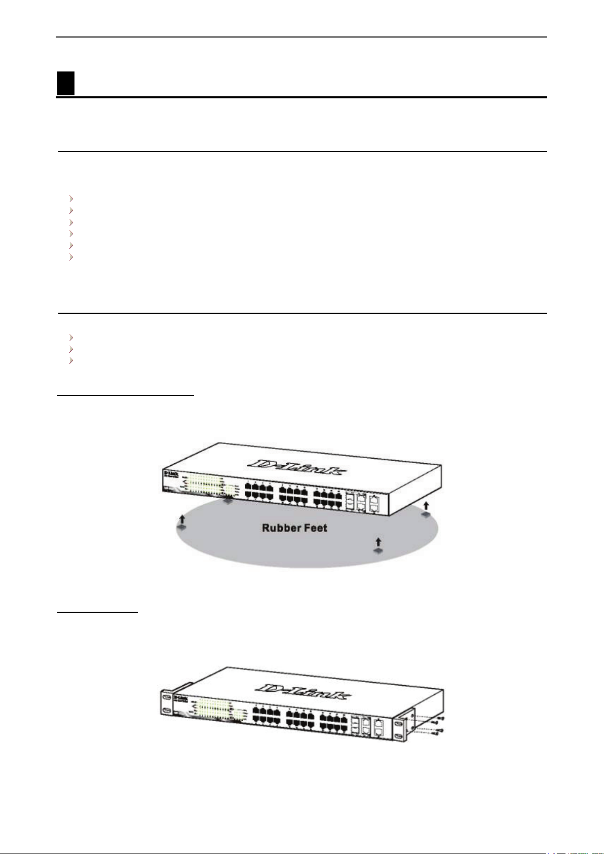
Desktop or Shelf Installation
When installing the switch on a desktop or shelf, the rubber feet included with the device must be attached
on the bottom at each corner of the device’s base. Allow enough ventilation space between the device and
the objects around it.
Figure 2.1 – Attach the adhesive rubber pads to the bottom
Rack Installation
The switch can be mounted in an EIA standard size 19-inch rack, which can be placed in a wiring closet with
other equipment. To install, attach the mounting brackets to the switch’s side panels (one on each side) and
secure them with the screws provided (with 8 M3*6.0 size screws).
Figure 2.2 – Attach the mounting brackets to the Switch
Then, use the screws provided with the equipment rack to mount the switch in the rack.
6
Page 12

2 Hardware Installation D-Link Web Smart Switch User Manual
Figure 2.3 – Mount the Switch in the rack or chassis
Please be aware of following safety Instructions when installing:
A) Elevated Operating Ambient - If installed in a closed or multi-unit rack assembly, the operating ambient
temperature of the rack environment may be greater than room ambient. Therefore, consideration should be
given to installing the equipment in an environment compatible with the maximum ambient temperature (Tma)
specified by the manufacturer.
B) Reduced Air Flow - Installation of the equipment in a rack should be such that the amount of air flow
required for safe operation of the equipment is not compromised.
C) Mechanical Loading - Mounting of the equipment in the rack should be such that a hazardous condition is
not achieved due to uneven mechanical loading.
D) Circuit Overloading - Consideration should be given to the connection of the equipment to the supply
circuit, and the effect that overloading of the circuits might have on overcurrent protection and supply wiring.
Appropriate consideration of equipment nameplate ratings should be used when addressing this concern.
E) Reliable Earthing - Reliable earthing of rack-mounted equipment should be maintained. Particular
attention should be given to supply connections other than direct connections to the branch circuit (e.g. use
of power strips)."
Step 3 – Plugging in the AC Power Cord
Users may now connect the AC power cord into the rear of the switch and to an electrical outlet (preferably
one that is grounded and surge protected).
Figure 2.4 –Plugging the switch into an outlet
77
Page 13

2 Hardware Installation D-Link Web Smart Switch User Manual
Power Failure
As a precaution, the switch should be unplugged in case of power failure. When power is resumed, plug the
switch back in.
8
Page 14

3 Getting Started D-Link Web Smart Switch User Manual
3 Getting Started
This chapter introduces the management interface of D-Link SmartPro Switch.
Management Options
The D-Link SmartPro Switch can be managed through any port on the device by using the Web-based
Management, or through any PC using the SmartConsole Utility or CLI commands.
Each switch must be assigned its own IP Address, which is used for communication with the Web-Based
Management or a SNMP network manager. The PC should have an IP address in the same range as the
switch. Each switch can allow up to four users to access the Web-Based Management concurrently.
However, if you want to manage multiple D-Link SmartPro Switches, the SmartConsole Utility and Single IP
Management are more convenient choice. By using the SmartConsole Utility, you do not need to change the
IP address of your PC and it is easier to initialize multiple Smart Switches.
Please refer to the following installation instructions for the Web-based Management and the SmartConsole
Utility.
Using Web-based Management
After a successful physical installation, you can configure the Switch, monitor the network status, and display
statistics using a web browser.
Supported Web Browsers
The embedded Web-based Management currently supports the following web browsers:
Internet Explorer 6 or later version
Netscape 8 or later version
Chrome 5.0 or later version
Firefox 3.0 or later version
Opera 10 or later version
Connecting to the Switch
You will need the following equipment to begin the web configuration of your device:
1. A PC with a RJ-45 Ethernet connection
2. A standard Ethernet cable
Connect the Ethernet cable to any of the ports on the front panel of the switch and to the Ethernet port on the
PC.
Figure 3.1 – Connected Ethernet cable
99
Page 15

3 Getting Started D-Link Web Smart Switch User Manual
Login Web-based Management
In order to login and configure the switch via an Ethernet connection, the PC must have an IP address in the
same subnet as the switch. For example, if the switch has an IP address of 10.90.90.90, the PC should have
an IP address of 10.x.y.z (where x/y is a number between 0 ~ 254 and z is a number between 1 ~ 254), and
a subnet mask of 255.0.0.0. There are two ways to launch the Web-based Management, you may either click
the Web Access button at the top of the SmartConsole Utility or open the web browser and enter 10.90.90.90
(the factory-default IP address) in the address bar. Then press <Enter>.
Figure 3.2 –Enter the IP address 10.90.90.90 in the web browser
NOTE: The switch's factory default IP address is
10.90.90.90 with a subnet mask of 255.0.0.0 and
a default gateway of 0.0.0.0.
The web configuration can also be accessed through the SmartConsole Utility. Open the SmartConsole
Utility and double-click the switch as it appears in the Monitor List. This will automatically load the web
configuration in your web browser.
When the following logon dialog box appears, enter the password and choose the language of the Webbased Management interface then click OK.
The switch supports 10 languages including English, Traditional Chinese, Simplified Chinese, German,
Spanish, French, Italian, Portuguese, Japanese and Russian. By default, the password is admin and the
language is English.
Figure 3.3 – Logon Dialog Box
Smart Wizard
After a successful login, the Smart Wizard will guide you through essential settings of the D-Link Web Smart
Switch. Please refer to the Smart Wizard Configuration section for details.
Web-based Management
By clicking the Exit button in the Smart Wizard, you will enter the Web-based Management interface. Please
refer to Chapter 5
Configuration for detailed instructions.
SmartConsole Utility
The SmartConsole Utility included in the installation CD is a program for discovering D-Link Smart Switches
within the same network segment connected to your PC. This tool is only for computers running Windows
2000, Windows XP, Windows 7, or Windows Vista operating systems. There are two options for the
installation of the SmartConsole Utility; one is through the autorun program on the installation CD and the
other is manual installation.
10
Page 16

3 Getting Started D-Link Web Smart Switch User Manual
SmartConsole Utility from your PC before
with IPv4
NOTE: Please be sure to uninstall any existing
installing the latest SmartConsole Utility.
Option 1: Follow these steps to install the SmartConsole Utility via the autorun program on the installation
CD.
1. Insert the Utility CD into your CD-Rom/DVD-Rom Drive.
2. The autorun program will appear automatically.
3. Click on the ”Install SmartConsole Utility” button and an installation wizard will guide you through the
process.
4. After successfully installing the SmartConsole Utility, you can open the utility by clicking Start >
Programs > D-Link SmartConsole Utility.
5. Connect the Smart Switch to the same L2 network segment of your PC and use the SmartConsole
Utility to discover the Smart Switches.
Option 2: Follow these steps to install the SmartConsole Utility manually.
1. Insert the Utility CD into your CD-Rom/DVD-Rom Drive.
2. From the Start menu on the Windows desktop, click Run.
3. In the Run dialog box, type D:\D-Link SmartConsole Utility\D-Link_SmartConsole_Utility_v3.00.10.exe
(where D:\ represents the drive letter of your CD-Rom) and click OK.
4. Follow the on-screen instructions to install the utility.
5. Upon completion, go to Start > Programs > D-Link SmartConsole Utility and open the SmartConsole
Utility.
6. Connect the Smart Switch to the same L2 network segment of your PC and use the SmartConsole
Utility to discover the Smart Switches.
For detailed explanations of SmartConsole’s functions, please refer to Chapter 4 SmartConsole Utility
NOTE: The current SmartConsole Utility does not
support IPv6 feature. Please be sure to install the
SmartConsole Utility from you PC
address. After installed SmartConsole Utility, then
it can discover the DGS-1500 series with IPv6
address.
1111
Page 17
4 SmartConsole Utility D-Link Web Smart Switch User Manual
4 SmartConsole Utility
The D-Link SmartConsole Utility allows the administrator to quickly discover all D-Link smart switches, which
are in the same domain of the PC, collect traps and log messages, and quick access to basic configurations
of the switch.
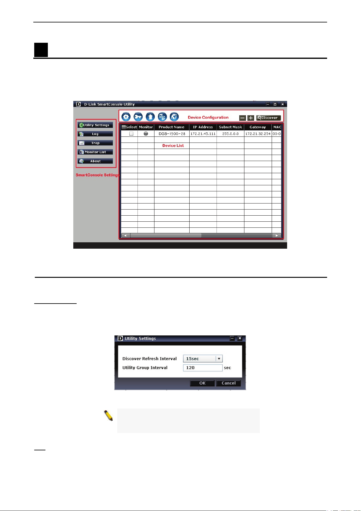
The SmartConsole Utility consists of three parts, Device Configurations at the top, Device List as the main
body, and SmartConsole Settings at the left.
Figure 4.1 – SmartConsole Utility
SmartConsole Settings
The SmartConsole Settings at the left has five icons, Utility Settings, Log, Trap, Monitor list, and About.
Utility Settings
Click this icon to launch the Utility Settings window. Refresh time refreshes the devices, which were
selected as monitored devices in the Device List. Choices include 15 secs, 30 secs, 1 mins, 2 mins, and 5
mins for selecting the monitoring time intervals. Utility Group Interval establishes the intervals (in seconds)
that the Switch will be discovered in the SmartConsole Device List.
Figure 4.2 – SmartConsole Utility Settings
NOTE: If the Group Interval is set to 0, IGMP
Snooping must be disabled in the Switch, or the
SmartPro Switch will not be discovered.
Log
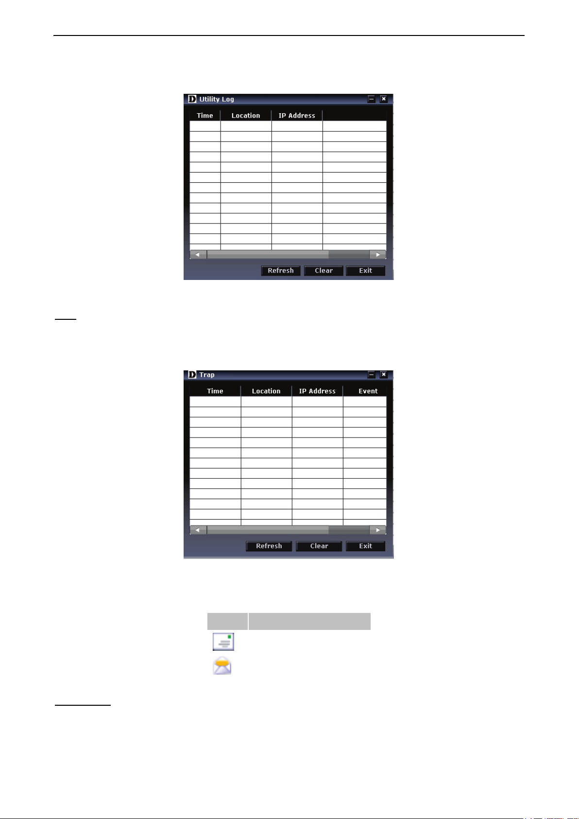
Click this icon to launch the Log window. Click View Log to show the events of the SmartConsole Utility and
the device. Time indicates when the message was received, Location indicates where the message was
12
Page 18
4 SmartConsole Utility D-Link Web Smart Switch User Manual
received and IP Address denotes where it comes from. Click Refresh to redisplay all log entries, click Clear
to clear all log entries. Click Exit to exit.
Figure 4.3 – SmartConsole Log
Trap
Click this icon to launch the Trap window. Click View Trap to show the events of the SmartConsole Utility
and the device. Time indicates when the trap message was received, Location indicates where the trap
message was received, IP denotes where it comes from and Event shows the content of this trap message.
Click Refresh to redisplay all traps, click Clear to clear all entries. Click Exit to exit
Figure 4.4 – SmartConsole Trap
The trap icon in the SmartConsole Settings will change while receiving new trap messages. Please see
below for detailed description.
Icon Description
No new traps
New traps was received
Monitor List
By clicking on this icon you will see below options:
1133
Page 19

4 SmartConsole Utility D-Link Web Smart Switch User Manual
Figure 4.5 – SmartConsole Monitor List
Save: Records the setting of the Device List as default for the next time the SmartConsole Utility is used.
Save As: Records the setting of the Device List in an appointed filename and file path.
Restore: Manually reload a Device List setting file.
About
Click this icon to launch the SmartConsole Info window.
Figure 4.6 – SmartConsole About
Device Configuration
The Device Configuration in the SmartConsole Utility has five icons:
Device Settings
Password Settings
Firmware Upgrade
DHCP Refresh
Web Access
and the
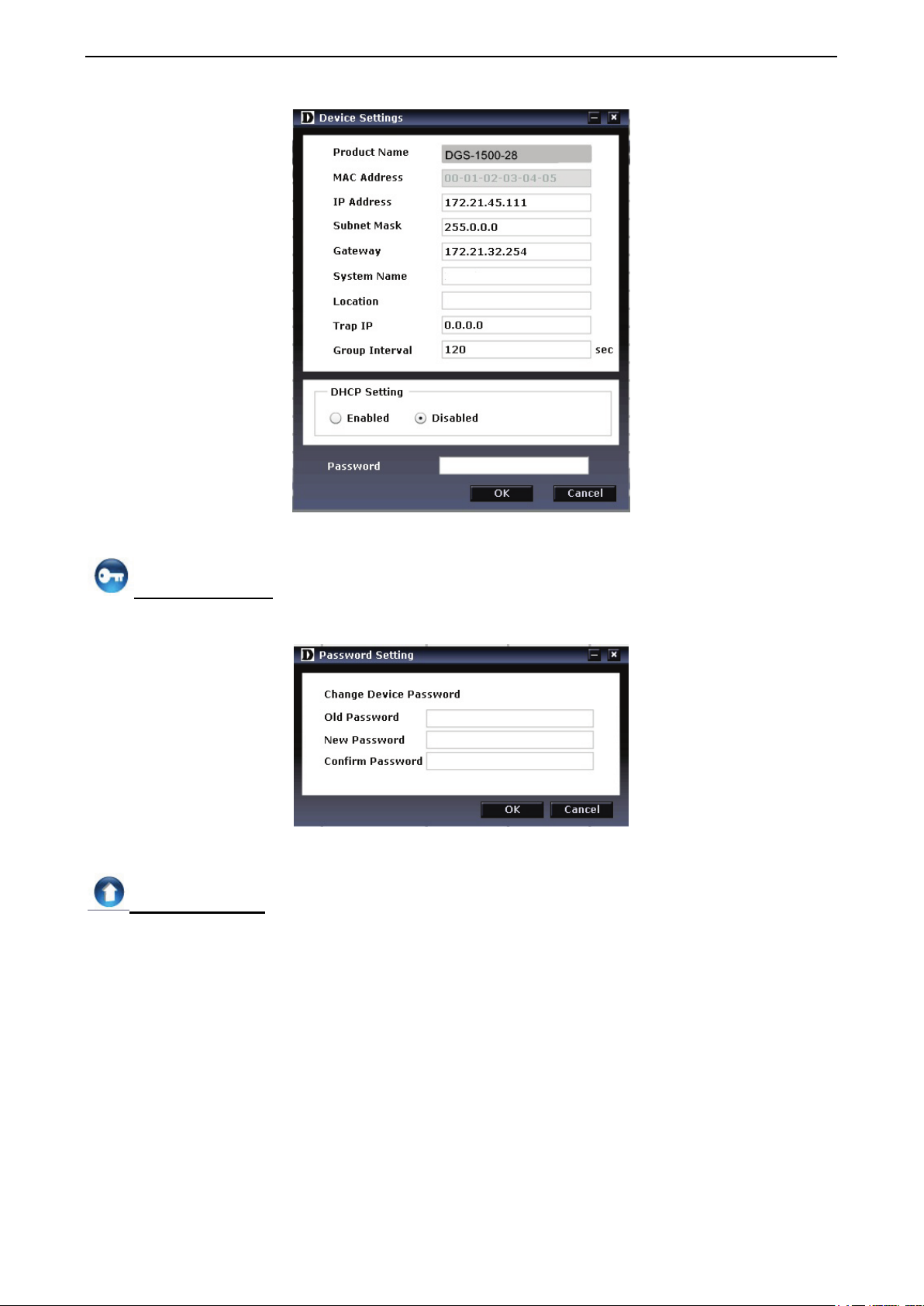
Select a switch from the Device List. Click on this icon to launch the Device Settings window. Here you can
configure the Product Name, MAC Address, IPv4 Address, Subnet Mask, Gateway, System Name, Location,
Trap IP, Group Interval, and DHCP Client Setting of the Switch.
To apply the configuration, insert the correct device password in the Confirm Password box and then click
OK.
, , device buttons for the Device List.
Device Settings
14
Page 20
4 SmartConsole Utility D-Link Web Smart Switch User Manual
Figure 4.7 – SmartConsole Device Settings
Password Settings
Select a switch from the Device List. Click on this icon to launch the Device Password Manager window.
Here you can enter a new password and confirm it.
Figure 4.8 – SmartConsole Password Settings
Firmware Upgrade
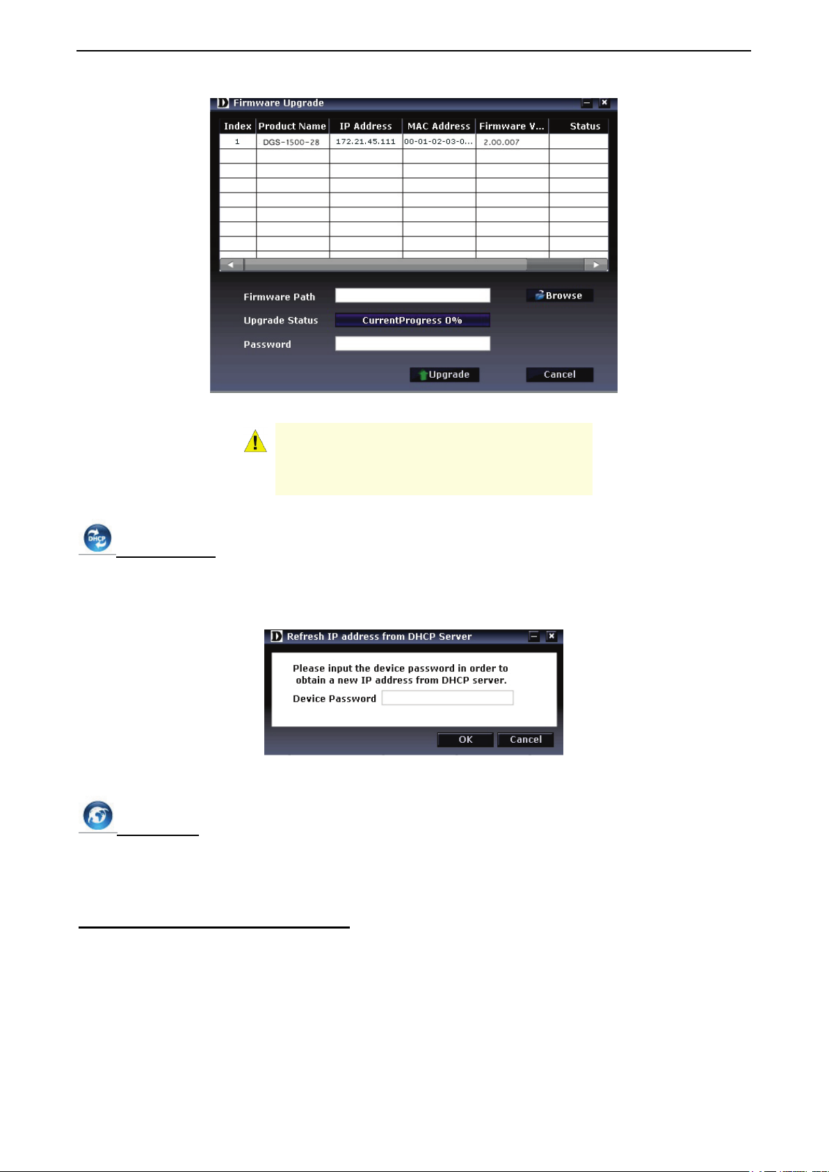
Select one or many switches of the same model name from the Device List. Click on this icon to launch the
Firmware Upgrade window. Specify the Firmware Path (or Browse for one) that you are going to use. Input
the correct password of the device, and then click Upgrade. The state will show "OK" after completion, or
“Fail” if the firmware upgrade fails or cannot be completed for any reason.
1155
Page 21
4 SmartConsole Utility D-Link Web Smart Switch User Manual
Figure 4.9 – Firmware Upgrade
CAUTION: Do not disconnect the PC or remove
the power cord from the device until the upgrade
completes. The software may be corrupted
because of the incomplete firmware upgrade.
DHCP Refresh:
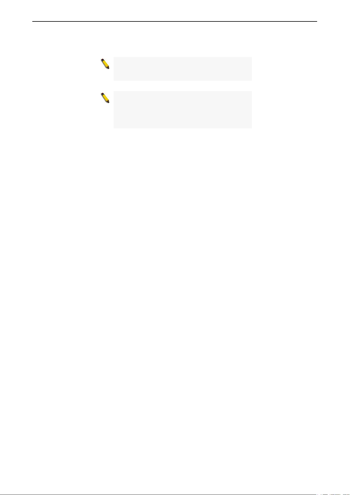
If a DHCP-client enabled switch in the Device List shows the default IP is still used, it means the device did
not receive an IPv4 address from the DHCP server successfully. Select that switch and click the DHCP
refresh icon. Enter the correct Device Password and then click OK. The device will renew the IPv4 address
from the DHCP server.
Figure 4.10 – DHCP Refresh
Web Access
Select a switch from the Device List. Click this icon to launch your Internet browser (eg. The Internet
Explorer). Here you can configure the Switch through the Web-based Management utility. You may also get
into the Web-based Management by double-clicking the device in the device list.
Add(+), Delete(-) and Discover the device
Click the Discovery button to display all of the Web-Smart devices located in the same domain with the
management PC.
Click the + and insert a device IP address to add a device into the Discover List, or select a device and click
the – button to remove it.
16
Page 22

4 SmartConsole Utility D-Link Web Smart Switch User Manual
Figure 4.11 – SmartConsole Add device
Figure 4.12 – SmartConsole Delete device
Device List
This list displays all discovered Web-Smart devices on the network.
Figure 4.13 – SmartConsole Device List
Definitions of the Device List features:
Select: Click the Select to choose a switch for configuration settings.
Monitor: Click the Monitor button and the SmartConsole will collect the trap and log data from the device.
The
in the monitor means the device was discovered by SmartConsole. Click the icon to have the
device to continue updating the information, such as system log or trap to the SmartConsole Utility. The icon
will appear
. When the device was detected as not reachable, the icon will change to . Please check
if the power or the cable of this device is disconnected.
Product Name: Displays the device product name.
IP Address: Displays the current IP addresses of devices.
Subnet Mask: Displays the Subnet Mask setting of the device.
Gateway: Displays the Gateway setting of the device.
MAC Address: Displays the device MAC Addresses.
Firmware version: Displays the current Firmware version of this device.
System Name: Displays the appointed device system name.
Location: Displays the location of the appointed device.
SNMP: Displays the SNMP status of the device.
Trap IP: Displays the IP address of the host where the Trap information will be sent.
DHCP: Specify if the device gets the IP address from a DHCP server.
1177
Page 23
4 SmartConsole Utility D-Link Web Smart Switch User Manual
Group Interval: Displays the intervals (in seconds) that the Switch will be discovered in the SmartConsole
Device List.
NOTE: If the devices are marked red in the device
list, it means that a firmware upgrade is required
again.
NOTE: If the IP address of device is showed with
IPv6 address, then it can not be configured with
Smartconsole Utility. The user needs to double
click the selected device and login the web for
configuration.
18
Page 24
5 Configuration D-Link Web Smart Switch User Manual
5 Configuration
The features and functions of the D-Link SmartPro Switch can be configured for optimum use through the
Web-based Management Utility.
Smart Wizard Configuration
After a successful login, the Smart Wizard will guide you through essential settings of the D-Link Web Smart
Switch. If you do not plan to change anything, click Exit to leave the Wizard and enter the Web Interface.
You can also skip it by clicking Don’t show Smart Wizard next time for the next time you logon to the Webbased Management.
IPv4 Information
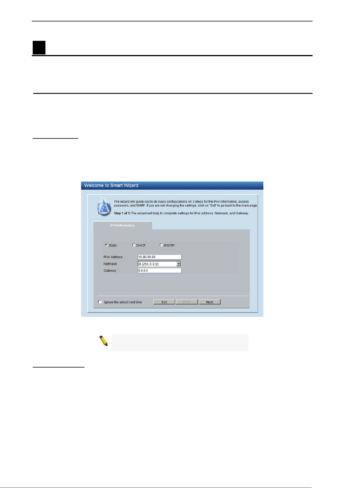
IPv4 Information will guide you to do basic configurations on 3 steps for the IP Information, access password, and
SNMP.
the Gateway address, then click the Apply button to enter the next Password setting page. (No need to
enter IP Address, Netmask and Gateway of DHCP and BOOTP selection.) The IP address is allowed for
IPv4 and IPv6 address.
click on Ignore the wizard next time to skip wizard setting when the switch boots up.
Select Static, DHCP or BOOTP, and type the desired new IP Address, select the Netmask and type
If you are not changing the settings, click Exit button to go back to the main page. Or you can
Figure 5.1 – IPv4 Information in Smart Wizard
NOTE: The IPv4 Information of Smart Wizard
does not support IPv6 address.
Password Settings Type the desired new password in the Password box and again in the Confirm Password, then click the
Next button to the SNMP setting page.
1199
Page 25

5 Configuration D-Link Web Smart Switch User Manual
Figure 5.2 – Password setting in Smart Wizard
SNMP Settings
The SNMP Setting allows you to quickly enable/disable the SNMP function. The default SNMP Setting is
Disabled. Click Enabled and then click Apply to make it effective.
Figure 5.3 – SNMP Setting in Smart Wizard
NOTE: Changing the system IP address will
disconnect you from the current connection.
Please enter the correct IP address in the Web
browser again and make sure your PC is in the
same subnet with the switch. See Login Webbased Management for a detailed description.
20
Page 26

5 Configuration D-Link Web Smart Switch User Manual
If you close the web browser without
If you want to change the IP settings, click OK and start a new web browser.
Figure 9 – Confirm the changes of IP address in Smart Wizard
Web-based Management After clicking the Exit button in Smart Wizard you will see the screen below:
Figure 5.4 – Web-based Management
The above image is the Web-based Management screen. The three main areas are the Tool Bar on top, the
Function Tree, and the Main Configuration Screen.
The Tool Bar provides a quick and convenient way for essential utility functions like firmware and
configuration management.
By choosing different functions in the Function Tree, you can change all the settings in the Main
Configuration Screen. The main configuration screen will show the current status of your Switch by clicking
the model name on top of the function tree.
At the upper right corner of the screen the username and current IP address will be displayed.
Under the username is the Logout button. Click this to end this session.
NOTE:
clicking the Logout button first, then it will be seen
as an abnormal exit and the login session will still
be occupied.
2211
Page 27

5 Configuration D-Link Web Smart Switch User Manual
Finally, by clicking on the D-Link logo at the upper-left corner of the screen you will be redirected to the local
D-Link website.
Tool Bar > Save Menu
The Save Menu provides Save Configuration and Save Log functions.
Figure 5.5 – Save Menu
Save Configuration
Select to save the entire configuration changes you have made to the device to switch’s non-volatile RAM.
Figure 5.6 – Save Configuration
Save Log
Save the log entries to your local drive and a pop-up message will prompt you for the file path. You can view
or edit the log file by using text editor (e.g. Notepad).
Figure 5.7 – Save Log
Tool Bar > Tool Menu
The Tool Menu offers global function controls such as Reset, Reset System, Reboot Device, Configuration
Backup and Restore, Firmware Backup and Upgrade.
Figure 5.8 – Tool Menu
Reset
Provide a safe reset option for the Switch. All configuration settings in non-volatile RAM will be reset to
factory default except for the IP address.
Figure 5.9 – Tool Menu > Reset
Reset System
Provide another safe reset option for the Switch. All configuration settings in non-volatile RAM will reset to
factory default and the Switch will reboot.
22
Page 28

5 Configuration D-Link Web Smart Switch User Manual
Figure 5.10 – Tool Menu > Reset System
Reboot Device Provide a safe way to reboot the system. Click Reboot to restart the switch.
Figure 5.11 – Tool Menu > Reboot Device
Configuration Backup and Restore
Allow the current configuration settings to be saved to a file (not including the password), and if necessary,
you can restore configuration settings from this file. Two methods can be selected: HTTP or TFTP.
Figure 5.12 – Tool Menu > Configure Backup and Restore
HTTP: Backup or restore the configuration file to or from your local drive.
Click Backup to save the current settings to your disk.
Click Browse to browse your inventories for a saved backup settings file.
Click Restore after selecting the backup settings file you want to restore.
TFTP: TFTP (Trivial File Transfer Protocol) is a file transfer protocol that allows you to transfer files to a
remote TFTP server. Select IPv4 or IPv6 and specify TFTP Server IP Address and TFTP File Name for the
configuration file you want to save to / restore from. The maximum Telnet Server connection is 4.
Click Backup to save the current settings to the TFTP server.
Click Restore after selecting the backup settings file you want to restore.
Note: Switch will reboot after restore, and
all current configurations will be lost
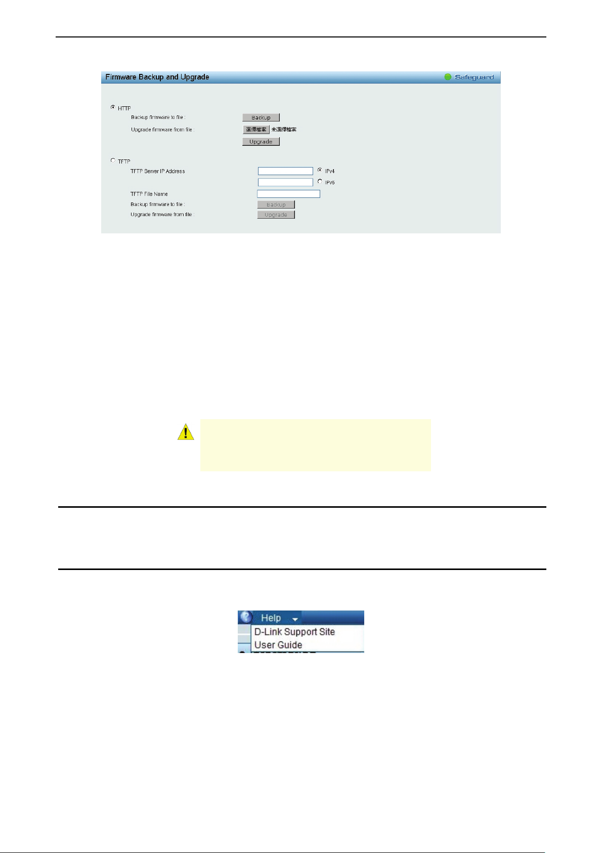
Firmware Backup and Upgrade
Allow for the firmware to be saved, or for an existing firmware file to be uploaded to the Switch. Two methods
can be selected: HTTP or TFTP.
2233
Page 29
5 Configuration D-Link Web Smart Switch User Manual
Figure 5.13 – Tool Menu > Firmware Backup and Upload
HTTP: Backup or upgrade the firmware to or from your local PC drive.
Click Backup to save the firmware to your disk.
Click Browse to browse your inventories for a saved firmware file.
Click Upgrade after selecting the firmware file you want to restore.
TFTP: Backup or upgrade the firmware to or from a remote TFTP server. Select IPv4 or IPv6 and specify
TFTP Server IP Address and TFTP File Name for the configuration file you want to save to / restore from.
The maximum Telnet Server connection is 4.
Click Backup to save the firmware to the TFTP server.
Click Upgrade after selecting the firmware file you want to restore.
CAUTION: Do not disconnect the PC or remove
the power cord from device until the upgrade
completes. The Switch may crash if the
Firmware upgrade is incomplete.
Tool Bar > Smart Wizard
By clicking the Smart Wizard button, you can return to the Smart Wizard if you wish to make any changes
there.
Tool Bar > Online Help
The Online Help provides two ways of online support: Online Support Site will lead you to the D-Link
website where you can find online resources such as updated firmware images; User Guide can offer an
immediate reference for the feature definition or configuration guide.
Figure 5.14 – Online Help
24
Page 30

5 Configuration D-Link Web Smart Switch User Manual
Figure 5.15 – User Guide Micro Site
2255
Page 31

5 Configuration D-Link Web Smart Switch User Manual
Function Tree
All configuration options on the switch are accessed through the Setup menu on the left side of the screen.
Click on the setup item that you want to configure. The following sections provide more detailed description
of each feature and function.
Figure 5.16 –Function Tree
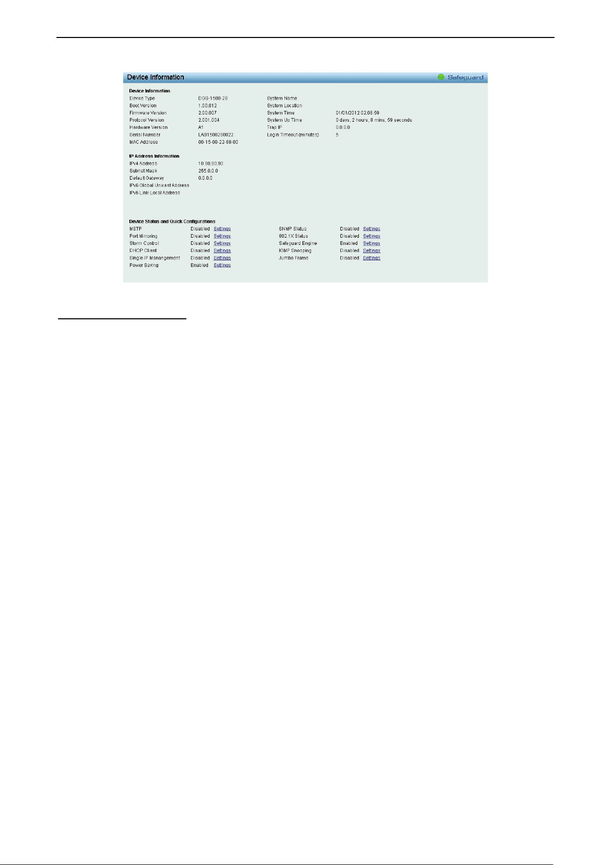
Device Information
The Device Information provides an overview of the switch, including essential information such as firmware
& hardware information, and IP address.
It also offers an overall status of common software features:
MSTP: Click Settings to link to L2 Functions > Spanning Tree > STP Bridge Global Settings. Default is
disabled.
Port Mirroring: Click Settings to link to L2 Functions > Port Mirroring. Default is disabled.
Storm Control: Click Settings to link to Security > Storm Control. Default is disabled.
DHCP Client: Click Settings to link to System > System Settings. Default is disabled.
Single IP Management: Click Settings to link to L3 Functions > Single IP Management > SIM Global
Settings. Default is disabled.
Power Saving: Click Settings to link to System > Power Saving. Default is enabled.
SNMP Status: Click Settings to link to SNMP > SNMP > SNMP Global Settings. Default is disabled.
802.1X Status: Click Settings to link to AAA > 802.1X > 802.1X Global Settings. Default is disabled.
Safeguard Engine: Click Settings to link to Security > Safeguard Engine. Default is enabled.
IGMP Snooping: Click Settings to link to L2 Functions > Multicast > IGMP Snooping. Default is disabled.
Jumbo Frame: Click Settings to link to L2 Functions > Jumbo Frame. Default is disabled.
26
Page 32
5 Configuration D-Link Web Smart Switch User Manual
Figure 5.17 – Device Information
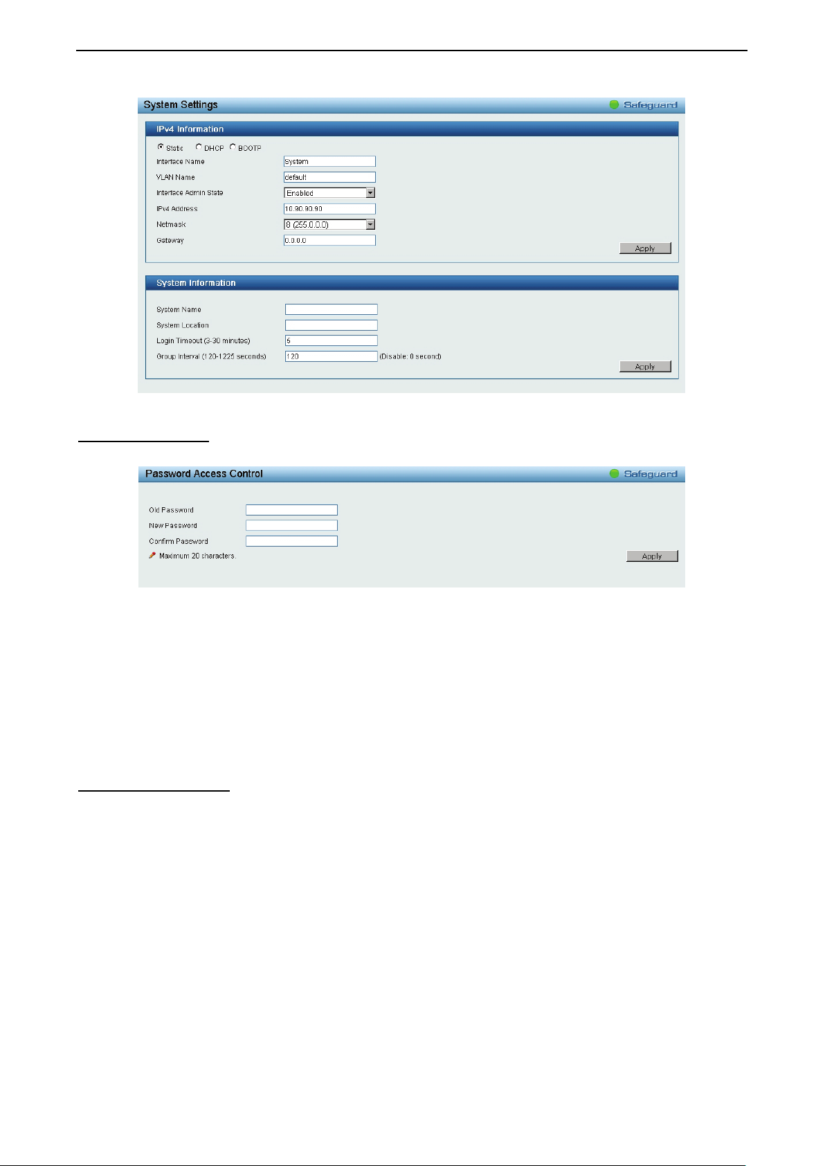
System > System Settings
The System Setting allows the user to configure the IP address and the basic system information of the
Switch.
IP Information: There are two ways for the switch to obtain an IP address: Static and DHCP (Dynamic Host
Configuration Protocol).
When using static mode, the IP Address, Subnet Mask and Gateway can be manually configured. When
using DHCP mode, the Switch will first look for a DHCP server to provide it with an IP address (including
network mask and default gateway) before using the default or previously entered settings. By default the IP
setting is static mode with IP address is 10.90.90.90 and subnet mask is 255.0.0.0.
System Information: By entering a System Name and System Location, the device can more easily be
recognized through the SmartConsole Utility and from other Web-Smart devices on the LAN.
Login Timeout: The Login Timeout controls the idle time-out period for security purposes, and when there is
no action for a specific time span in the Web-based Management. If the current session times out (expires),
the user is required a re-login before using the Web-based Management again. Selective range is from 3 to
30 minutes, and the default setting is 5 minutes.
Group Interval: The D-Link Web Smart Switch will routinely send report packets to the SmartConsole Utility
in order to maintain the information integrity. The user can adjust the Group Interval to optimal frequency.
Selective range is from 120 to 1225 seconds, and 0 means disabling the reporting function.
2277
Page 33
5 Configuration D-Link Web Smart Switch User Manual
Figure 5.18 – System > System Settings
System > Password
The Password page allows user to change the login password of the device.
Figure 5.19 – System > Password
To set the Password, set the following parameters and click Apply:
Old Password: If a password was previously configured for this entry, enter it here in order to change it to a
new password.
New Password: Enter the new password that you wish to set on the Switch to authenticate users attempting
to access Administrator Level privileges on the Switch. The user may set a password of up to 20 characters.
Confirm Password: Confirm the new password entered above. Entering a different password here from the
one set in the New Local Enabled field will result in a fail message.
System > Port Settings
In the Port Setting page, the status of all ports can be monitored and adjusted for optimum configuration. By
selecting a range of ports (From Port and To Port), the Speed can be set for all selected ports by clicking
Apply. Press the Refresh button to view the latest information.
28
Page 34

5 Configuration D-Link Web Smart Switch User Manual
Figure 5.20 – System > Port Settings
Speed: Gigabit Fiber connections can operate in 1000M Full Force Mode, Auto Mode or Disabled. Copper
connections can operate in Forced Mode settings (1000M Full, 100M Full, 100M Half, 10M Full, 10M Half),
Auto, or Disabled. The default setting for all ports is Auto.
NOTE: Be sure to adjust port speed settings
appropriately after changing the connected cable
media types.
MDI/MDIX:
A medium dependent interface (MDI) port is an Ethernet port connection typically used on the Network
Interface Card (NIC) or Integrated NIC port on a PC. Switches and hubs usually use Medium dependent
interface crossover (MDIX) interface. When connecting the Switch to end stations, user have to use
straight through Ethernet cables to make sure the Tx/Rx pairs match up properly. When connecting the
Switch to other networking devices, a crossover cable must be used.
This switch provides a configurable MDI/MDIX function for users. The switches can be set as an MDI port in
order to connect to other hubs or switches without an Ethernet crossover cable.
Auto MDI/MDIX is designed on the switch to detect if the connection is backwards, and automatically
chooses MDI or MDIX to properly match the connection. The default setting is “Auto” MDI/MDIX.
Flow Control: You can enable this function to mitigate the traffic congestion. Ports configured for full-duplex
use 802.3x flow control, half-duplex ports use backpressure flow control. The default setting is Disabled.
System > DHCP Auto Configuration
This page allows you to enable the DHCP Auto Configuration feature on the Switch. When enabled, the
Switch becomes a DHCP client and gets the configuration file from a TFTP server automatically on next boot
up. To accomplish this, the DHCP server must deliver the TFTP server IP address and configuration file
name information in the DHCP reply packet. The TFTP server must be up and running and store the
necessary configuration file in its base directory when the request is received from the Switch.
Figure 5.21 – System > DHCP Auto Configuration
2299
 Loading...