

Page 1
Page 2

Table of Contents
About this Guide .............................................
Rack Mounting ................................................
Installing Network Cables..............................
Station Connections with
. . .
Twisted-Pair Cable
Hub-to-Hub connections with
Twisted-Pair Cable
Thin Coaxial
Thick Coaxial Cable Connections
Connecting Power
LED Indicators.............................................
Specifications ................................................
Cable Connections.. .......
..........................................
......................................
...........................
....
...9
1
2
3
4
4
.7
9
10
11
Rev. 06 (April ‘98)
6DE824TP..06
Printed In China
Page 3
About this Guide
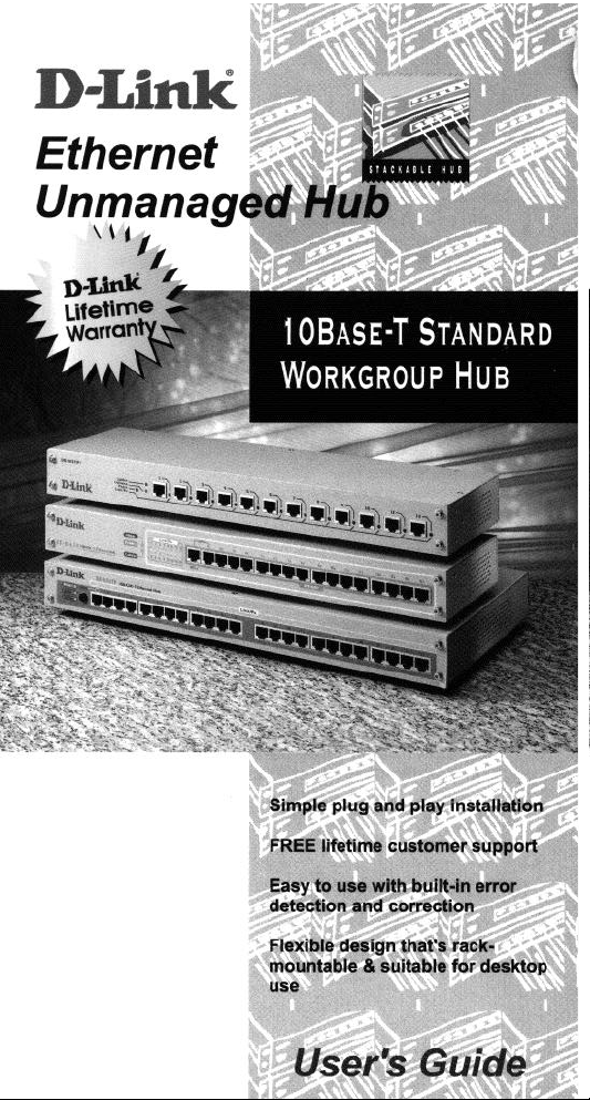
This guide provides instructions for instal-ling all
of the products described below. These D-Link@
Ethernet Hubs are all Plug and Play compliant for
easy installation.
/ -
DE81
2TP+
DE-81 6TP
DE-824TP
When designing your cable configuration, it is
necessary to strictly observe the Ethernet cabling
rules. This manual assumes familiarity with the
fundamental Ethernet cabling rules and limits; it
only describes the details of cable connection.
\
1
Page 4
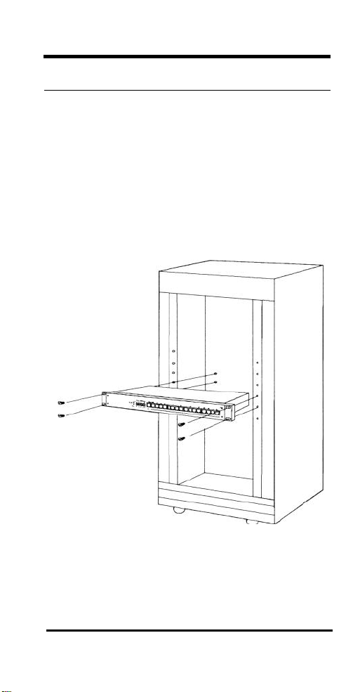
Rack Mounting
The Ethernet Hub may stand alone, or may be
mounted in a standard
Rack mounting produces an orderly installation
when you have a number of related network
devices. Use the six supplied screws to fasten the
supplied mounting brackets to either end of the
hub, then fasten the hub into the rack.
19-inch
equip-ment rack.
2
Page 5

Installing Network Cables
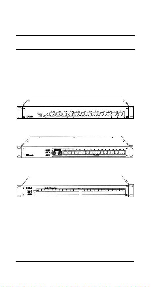
Your Ethernet Hub is denominated as an 12-port,
or 16-port, or
the number of its front-panel
Additionally it has two ports whose connectors are
on the rear panel: one lOBase2 port (BNC
connector), and one
These two un-numbered rear-panel ports are
logically equivalent with the numbered ports on
the front panel of the Ethernet Hub.
By using a rear-panel connector of the Ethernet
Hub to connect into an existing coaxial network
cable, you can add on a star-topology
connected through the Ethernet Hub’s numbered
front-panel ports. Alternatively, you can connect
into an existing star-topology through a front
panel port of the Ethernet Hub, and then add on a
bus-topology subnet by connecting the subnet bus
to a rear-panel connector of the Ethernet Hub
(irrespective of any star-topology subnet that may
also be supported by the Ethernet Hub’s
panel ports). In either case, the unused
panel connector always remains available to
connect a second coaxial cable (alternative type of
coaxial cable).
24-port
Ethernet Hub according to
lOBase5
port (AUI connector).
1OBaseT
ports.
subnet,
front-
rear-
When the Ethernet Hub has no coaxial trunk
connection, then both of the rear panel connectors
remain
connections.
when you have some station equipment whose
adapters have no 1OBaseT port (RI-45 connector),
and thus can only be connected to the hub through
a coaxial cable.
available for coaxial station-cable
It is useful to keep this in mind
3
Page 6

Connect each station to the Ethernet Hub by
means of a twisted-pair straight cable
cable, Category 3, 4, or 5). Plug one
(10BaseT
RJ-45
connector into a front-panel port of the Ethernet
Hub, and plug the other
RJ-45
connector into the
station’s Ethernet adapter.
w
RJ-45
connector
Hub-to-hub connection between Model
812TP+
Ethernet Hubs requires a
UTP cable
’
DE-
1OBaseT
crossover cable. In making a hub-to-hub
4
Page 7

connection involving a Model DE-816TP or Model
DE-824 Ethernet Hub, there is the alternative of
using a straight cable.
Internal Crossover Features
The Model DE-816TP Ethernet Hub and DE824TP Ethernet Hub feature internal cross-over
alternatives for Port 1:
+
Model DE-816TP Ethernet Hub
The port numbered as Port 1 is identical with
each of the other numbered ports. But Port 1
is specially equipped with an alternative
connector,
connector is wired to the same conductors as
the Port 1 connector, but with certain pin
positions interchanged to provide a crossover, and thus allow use of a straight cable to
make a hub-to-hub connection.
Keep in mind that the Uplink connector is not
an independent-port. It is only an alternative
connector to Port 1, to facilitate hub-to-hub
cabling. Port 1 is fully occupied whenever (1)
a hub-to-hub connection is made through its
Uplink
connection is made directly through the Port
1 connector
labeled
“Uplink.” The
connector, or (2) any kind of
Uplink
Below in this manual, the term
selected” will mean, as to the Model DE816TP Ethernet Hub in question, that the
subject connection is made through the
Uplink
connector
5
“Uplink
Page 8

+
Model DE-824TP Ethernet Hub
The connector numbered as Port 1 is equipped
with a switch
labeled “Uplink”
When the
Uplink switch is in the “off (tall) position, the
Port 1 connector is wired “straight” to the
supporting circuitry, and Port 1 is then
identical with each of the twenty-three other
numbered ports. When the
Uplink
switch is
in the “on” (depressed) position, a pin interchange is switched into the wiring for the
Port 1 connector, to provide a cross-over, and
thus allow use of a straight cable to make a
hub-to-hub connection.
Below in this manual, the term
“Uplink
selected” will mean, as to the Model DE-824TP
Ethernet Hub in question, that the subject
connection is made through Port 1 and the
Uplink
switch is in its “on” (depressed)
position.
Rules for Using the
Uplink
Feature
Uplink should never be selected for a station cable
connection. And
Uplink
should never be selected
for a hub-to-hub connection through a crossover
cable (because the crossover in the connector
wiring would cancel out the crossover in the
cable).
should be selected only for making a
Uplink
hubto-hub connection with a straight cable. When
Uplink
is selected at one end of a straight cable,
Uplink
must not be selected at other end of that
cable.
(If
Uplink
were selected at both ends of a
straight cable, then the built-in crossovers of the
6
Page 9

two connectors would cancel one another, and the
hub-to-hub connection would fail.)
Thus the rule for making a hub-to-hub connection
with twisted-pair cable is as follows:
To make a hub-to-hub connection with a
straight cable,
one end of the cable, and
Uplink
must
be selected at
Uplink
must not
be selected at the other end of the cable.
To make a hub-to-hub connection with a
cross-over cable,
Uplink
must not be
selected at either end of the cable.
To connect the Ethernet Hub to a thin coaxial
cable (lOBase2 cable, also known by its
standard name,
RG58A/U,
and a variety of other
wire-
informal names), first twist a BNC T-connector
onto the rear-panel BNC connector of the
Ethernet Hub. Then twist the shell of the cable’s
connector onto either leg of the BNC T.
If the thin coaxial cable continues on to other
nodes, then twist the shell of the continuation
cable onto the remaining leg of the BNC T. If
there is no continuation (the Ethernet Hub is at
the end of the coaxial cable), then it is necessary to
twist a
50-ohm
terminator onto the remaining
open leg of the BNC T.
7
Page 10

Thin coax Segment
v
Sometimes several Ethernet Hubs must be
colocated to support a larger array of stations than
can be handled by a single Ethernet Hub. Then it
is useful to stack the Ethernet Hubs by joining
their BNC connectors with 0.5 meter patches of
thin coaxial cable. Such stacking is just a special
case of thin coaxial cable connection as treated
above, and the terminator rule is the same: If the
stack is at the end of the incoming cable, then a
50-ohm terminator must be substituted for the
continuation cable shown in the stacking diagram
below.
Tonext
node
8
Page 11

To connect the Ethernet Hub to a thick coaxial
cable (lOBase cable), it is necessary to have a
lOBase Ethernet transceiver (tap) on the cable at
the Ethernet Hub’s position. Then run an
AUI
cable between the transceiver’s AUI connector and
the AUI connector on the rear panel of the Ethernet
Hub.
AUI port
-AU1
cable
Transceiver
x
Connecting Power
For compatibility with electric service in most
areas of the world, the Ethernet Hub’s power
supply automatically adjusts to line power in the
range 100
Per ordering option, either a Type 1 (US) or Type 2
(European) power cord is supplied with your
Ethernet Hub. See Spefications, below, for power
cord details.
Ascertain that the power switch on the rear panel
of the Ethernet Hub is in the off position.
female end of the power cord firmly into the
-
240 VAC and 50 - 60 Hz.
9
Plug the
Page 12

receptacle on the rear panel of the Ethernet Hub.
Plug the other end of the power cord into an
electric service outlet. Turn on power to the
Ethernet Hub by switching its rear-panel power
switch to the
on
position.
LED Indicators
LED indicators are located on the front panel of
the Ethernet Hub.
Jabber LED
One Jabber LED for all ports. This LED
flashes red when the Ethernet Hub detects a
data packet that is defective (exceeds allowable length). This kind of error will ordinarily
be managed by the offending Ethernet adapter
itself, in which case the Jabber LED will return to its normal off (dark) state.
Collision LED
One Collision LED for all ports. A collision
occurs when two stations within a collision
domain attempt to transmit at the same time.
Intermittent flashing yellow of the Collision
LED is normal; the contending adapters
resolve each collision by means of a
then-retransmit algorithm.
collisions is an indicator of heavy traffic on
the network.
Fre-quency of
wait-
10
Page 13

One Link/Rx LED for each numbered port.
Steady green
(Link
state) indicates that the
port has good linkage to its partner device.
Flashing green
(Receive
state) indicates that
the port is receiving data from its partner
device.
If the port is connected but the Link/Rx LED
is dark, check whether (1) the Ethernet Hub
and the partner device both have power, (2)
the port’s cable is firmly seated in its
connectors in the Ethernet Hub and in the
partner device, (3) the connecting cable is
good and is of the correct type, and
partner device, including any network
adapter, is functioning.
Specifications
(4)
the
Data transfer rate:
Protocol:
Topologies:
EMI Certification:
AC power:
Power consumption:
10
Mbps
CSMA/CD
Star, Bus
FCC Class A, VCCI 1, CE A
I
DE-812TP+:
DE-816TP:
DE-824TP:
11
18W
18W
2ow
Page 14

Dimensions:
Weight:
W x H x L, mm (including mounting
brackets):
DE-812TP+: 483x44 125
DE-81 6TP:
DE-824TP 483x44 211
DE-81 2TP+: 2.0 kg
DE-816TP: 2.0 kg
DE-824TP: 3.03 kg
483x44 125
Operating
temperature:
Humidity: 10
Power cord: Type 1 (US) or Type 2 (Europe) per
Plug Rating
Cord Rating
Length
Safety
Standard
-
55” c
0”
-
90 % non-condensing
I
125V, 7A
125V, 7A
1830mm
(6ft)
UL, CSA
12
25OV,
25OV,
1830mm
VDE
1OA
10A
(6ft)
Page 15

D-Link Office
USA
Canada
UK
Sweden
Australia
Denmark
Singapore
China
India
Taiwan
5
Musick, Irvine,
Tel. l-714-455-1688 Fax.1-714-455-2521
2180 Durwin Driver,
LSL 5M8,
Tel. l-905-828-0260 Fax. l-905-828-5669
D-Link House, 6 Garland Road, Stanmore,
London HA7 IDP, U.K.
Tel. 44-181-235-555s Fax. 44-181-235-5500
Auf Der
Tel. 49-6196-643011 Fax. 49-6196-28049
Le
Florilege
Fonteany
Tel. 33-l-30.23.86.88
World Trade Center,
Sweden
Tel. 46-08-70062 11 Fax. 46-08-219640
Unit 16,390 Eastern Valley Way,
Australia
Tel.
61-2-9417-7100
Naverlnnd
Tel. 45-43-96-90-40 Fax. 45-43-42-43-47
77 Science Park Drive,
Singapore Science Park, Singapore 118256
Tel. 65-7746233 Fax. 65-7746322
lOF, 8-8-15 Nishgotsndn, Shinagwa-ku, Tokyo 141,
Japan
Tel. 81-3-5434-9678 Fax. 81-3-5434-9868
15” Floor, Science & Technology
No. 11 Baishiqino Road, Haidinn District,
Beijing 100081, China
Tel. 86-10-68467106 Fax. 86-10-68467110
Plot
No.5, Kurla-Bandra Comples
OFF CST Rd.,
Tel. 91-22-61 l-2788
2F,
No.233-2,
Taiwan, R.O.C.
Tel. 886-2-9161600 For. 886-2-9146299
CA92618, U.S.A.
Canada
Krautweide 32,65812
Le Fleury, France
2 DK-2600
Unib#6,
2,
Allee
de la Fresnerie, 78330
Fax.
P.O.Box
Fax.
Glostrup
#03-03 CINTECH
Santacruz
Pao-Chiao Road,
Fax. 91-22-617-2476
(E) Bombay-400 098 India
Mississaugs, Ontario,
Bad
Soden,
Germany
33-l-30-23.86.89
70396,107 24
Roseville,
61-2-9417-1077
Copenhagen, Denmark
Tower1
Rd,
Hsin-Tiea,
Stockholm,
NSW 2069,
HI,
Taipei,
 Loading...